Tandberg Data T40 Users Manual StorageLibrary User Guide Rev 3 Sost
T40 to the manual adf941fd-88f7-4c59-a859-935f9855e2f8
2015-02-03
: Tandberg-Data Tandberg-Data-T40-Users-Manual-462563 tandberg-data-t40-users-manual-462563 tandberg-data pdf
Open the PDF directly: View PDF ![]() .
.
Page Count: 95
Installation and User Guide

ii
Copyright
©
2006 Tandberg Data ASA
The information contained in this document is subject to change without notice.
This document contains proprietary information which is protected by copyright. All rights are
reserved. No part of
this document may be reproduced, modified, distributed, or translated to another language without prior written
consent of Tandberg Data.
Tandberg Data ASA
Kjelsåsveien 161
P.O. Box 134 Kjelsås
N-
0411 Oslo, Norway
Tel: +47 22 18 90 90
Fax: +47 22 18 95 50
www.tandbergdata.com
This document may describe designs for which patents are pending, or have been granted. By publishing this
information, Tandberg Data conveys no license under any pate
nt or any other right.
Tandberg Data shall not be liable for errors contained herein or for incidental or consequential damages
(including lost profits) in connection with the furnishing, performance or use of this material whether based on
warranty, cont
ract, or other legal theory. Tandberg Data makes no representation or warranty with respect to the
contents of this document and specifically disclaims any implied warranties of merchantability or fitness for any
particular purpose. Further, Tandberg Data
reserves the right to revise or change this document without
obligation on the part of Tandberg Data to notify any person or organization of such revision or change.
Every effort has been made to acknowledge trademarks and their owners. All trademarks wit
hin this document
are the property of their respective owners. Trademarked names are used solely for identification or exemplary
purposes,
and
any omissions are unintentional.
Published:
January 2007
Part No.: 433599
-
02

StorageLibrary Installation and User Guide
iii
Table of Contents
1 About This Guide
1
Waste Electrical and Electronic Equipment Directive
..............................................................................
1
Product Model Number
.............................................................................................................................
1
Explanation of Symbols and Notes
..........................................................................................................
1
Other Documents You Might Need
..........................................................................................................
2
Getting More Information or Help
.............................................................................................................
2
2 Product Overview
3
Product Descri
ption
..................................................................................................................................
3
Tape Drive Support
............................................................................................................................
3
Data Transfer Rates
...........................................................................................................................
4
Magazines
..........................................................................................................................................
4
Front Panel
.........................................................................................................................................
4
Rear Panel
.........................................................................................................................................
5
Library Features
.......................................................................................................................................
6
Operator Interfaces
............................................................................................................................
6
ADI Bridging and LUN
........................................................................................................................
6
Partitions
............................................................................................................................................
7
Control Path
.......................................................................................................................................
7
I/E Station
...........................................................................................................................................
7
Simple Network Management Protocol (SNMP)
................................................................................
7
Capacity on Demand (COD)
..............................................................................................................
7
Browser Requirements
......................................................................................................................
8
3 Unpacking the St
orageLibrary
9
Finding a Location for the StorageLibrary
................................................................................................
9
Unpack
.....................................................................................................................................................
9
4 Installing the Library
11
Remove the Transport Locking Screws
................................................................................................
.
11
Mounting the StorageLibrary in a Rack
..................................................................................................
12
Mounting the Rack mount Ears
.......................................................................................................
13
Installing the Rails in a Rack
............................................................................................................
14
Instal
ling the Left Rail Assembly
......................................................................................................
14
Installing the Right Rail Assembly
...................................................................................................
14
Mounting the StorageLibrary to the Rack
........................................................................................
15
Installing the Library
...............................................................................................................................
16
Connecting Library Cables (SCSI)
...................................................................................................
16
Connecting Li
brary Cables (Fibre Channel)
....................................................................................
17

iv
Contents
System Power
-
on
.............................................................................................................................
18
Labeling Cartridges for the Barcode Reader
...................................................................................
19
5 Information about the Operator Interfaces
21
Front Panel Interface (FPI)
.....................................................................................................................
21
Scroll Funct
ion
................................................................................................................................
.
21
Remote Management Interface
..............................................................................................................
22
Menu Trees
............................................................................................................................................
22
Home Scre
en
..........................................................................................................................................
28
Operator Privileges
................................................................................................................................
.
29
Words Commonly Used on the FPI and RMI
.........................................................................................
30
6 Configuring the Library
33
About the Setup Wizard
..........................................................................................................................
33
Using the Default Administrative User Account (Administrator)
......................................................
33
Using the Setup Wizard
...................................................................................................................
34
Setup Wizard Tasks
.........................................................................................................................
34
Configuri
ng Network Settings
.................................................................................................................
35
Remote Access
................................................................................................................................
36
Applying a License Key
..........................................................................................................................
36
Configuring I/E Slots
...............................................................................................................................
37
Configuring Cleaning Slots
.....................................................................................................................
37
Configuring Partitions
.............................................................................................................................
38
Creating Partitions
...........................................................................................................................
38
Reconfigure Partitions
......................................................................................................................
39
Changing Partition Modes
................................................................................................................
39
Setting Drive ID
......................................................................................................................................
40
Modifying the Control Path
.....................................................................................................................
40
Configuring Autoclean
............................................................................................................................
41
Configuring FPI Password
......................................................................................................................
41
Configuring RMI Password
.....................................................................................................................
42
Configuring Men
u Timeout
.....................................................................................................................
42
Setting Date and Time
............................................................................................................................
42
Configuring Barcode Scan
.....................................................................................................................
42
Configuring Audible Alarm
......................................................................................................................
43
Configuring SNMP
..................................................................................................................................
43
Configuring E
-
mail Notification
...............................................................................................................
43
7 Running the Library
45
Logging In
...............................................................................................................................................
45
Logging Out
............................................................................................................................................
45
Importing Cartridges
...............................................................................................................................
45
Importing Cartridges via I/E Slot
......................................................................................................
46
Import Cartridges via Bulk Loading of Magazi
nes
...........................................................................
47
Exporting Cartridges
...............................................................................................................................
47
Loading to Tape Drives
..........................................................................................................................
47
Unlo
ading from Tape Drives
...................................................................................................................
47
Cleaning Tape Drives
.............................................................................................................................
48
Importing Cleaning Media
................................................................................................................
48
Cleaning Media Handling
.................................................................................................................
48
Exporting Cleaning Media
................................................................................................................
48
Autoclean
.........................................................................................................................................
48
Manual Clean
...................................................................................................................................
49
Taking the Library Online/Offline
............................................................................................................
49
Taking a Library Online
....................................................................................................................
49
Taking a Library Offline
....................................................................................................................
49

StorageLibrary Installation and User Guide
v
Magazine Handling
................................................................................................................................
.
49
Standby Functionality
.............................................................................................................................
52
8 Getting Status and Information
53
Viewing Library Settings
.........................................................................................................................
53
Viewin
g Partitions/Drive Settings
...........................................................................................................
53
Viewing Network Settings
.......................................................................................................................
54
Viewing Statistics
....................................................................................................................................
54
Viewing Log
............................................................................................................................................
55
9 Adding, Removing and Replacing
57
Power Supply Unit
..................................................................................................................................
57
Removing and Replacing a Power Supply
......................................................................................
57
Tape Drive Unit
.......................................................................................................................................
58
Adding a Tape Drive
........................................................................................................................
58
Permanently Removing a Tape Drive
..............................................................................................
59
Removing and Replacing a Tape Drive
...........................................................................................
59
10 Updating Firmware
61
Updating Library Firmware
.....................................................................................................................
61
Updating Drive Firmware
........................................................................................................................
62
11 Working With Cartridges and Barcodes
65
Handling Cartridges Properly
.................................................................................................................
65
Write
-
Protecting Cartridges
....................................................................................................................
66
Barcode Requirements
...........................................................................................................................
66
Installing Barcode Labels
.......................................................................................................................
66
12 Tro
ubleshooting
67
About RAS Tickets
................................................................................................................................
.
67
Viewing RAS Tickets
........................................................................................................................
67
C
losing RAS Tickets
........................................................................................................................
68
Supported RAS Tickets
....................................................................................................................
68
Interpreting LEDs
....................................................................................................................................
70
The Maintenance Menus
.................................................................................................................
71
The Diagnostics Menu
.....................................................................................................................
71
Verifying Hardware
................................................................................................................................
.
71
Software Checking
................................................................................................................................
.
72
Verifying Recent Changes
......................................................................................................................
72
Troubleshooting Matrix
...........................................................................................................................
72
13 Shipping or Transporting StorageLibrary
79
Reinserting the Transport Locking Screws
.............................................................................................
79
Packi
ng the StorageLibrary
....................................................................................................................
80
14 Specifications
81
Library Dimensions
................................................................................................................................
.
82
Library Component Weights
...................................................................................................................
82
Power Requirements
..............................................................................................................................
83

vi
Contents
Climatic Specifications
............................................................................................................................
83
15 Safety and Regulatory Information
85
Safety Approvals
....................................................................................................................................
85
EMC Approvals
.......................................................................................................................................
85
Europe
..............................................................................................................................................
85
USA
..................................................................................................................................................
85
Japan
...............................................................................................................................................
86
Canada
.............................................................................................................................................
86
Conformity Declarations
.........................................................................................................................
86
Europe
..............................................................................................................................................
86
Australia
/New Zealand
.....................................................................................................................
86
16 Approved Drive Types
87
StorageLibrary Installation and User Guide
vii
Figures
Figure 1. Front Panel of the StorageLibrary
.............................................................................................
4
Figure 2. Rear Panel of the StorageLibrary with 1 Full
-
Height SCSI Drive Installed
...............................
5
Figure 3. Transport Locking Screws Marked
with Red Plastic Tabs
......................................................
11
Figure 4. Recommended Storage of Transport Locking Screws
...........................................................
12
Figure 5. Rackmounting Kit with Rackmoun
t Ears (Right figure)
...........................................................
13
Figure 6. Mounting the Rackmount Ears
................................................................................................
13
Figure 7. Rackmount Rail
.......................................................................................................................
14
Figure 9. StorageLibrary Mounted in a Rack, Front View
......................................................................
15
Figure 10. StorageLibrary Mounted in a Rack, Rear View
.....................................................................
16
Figure 11. StorageLibrary Cabling (SCSI)
..............................................................................................
16
Figure 12. StorageLibrary Cabling (Fibre Channel)
...............................................................................
18
Figure
13. Positioning of Barcode Label for LTO Cartridges
................................................................
.
19
Figure 14 Front Panel Interface Menu Tree
...........................................................................................
23
Figure 15 Remote Manageme
nt Interface Top Level Menu Tree
..........................................................
26
Figure 16. RMI Home Screen
.................................................................................................................
29
Figure 17. Map Menu
.............................................................................................................................
31
Figure 18. Removing the Magazine from the Library
.............................................................................
50
Figure 19. Gently Push the Cartridge into the Magazine Slot
................................................................
50
Figure 20. Push the Release Knob towards the Cartridge to Eject the Cartridge from the Slot
............
51
Figure 21. Push Magazine until it Clicks into Place
...............................................................................
51
Figure 22. The Release Tool Inserted into the Correct Hole on the Left Lower Magazine
....................
52
Figure 23. Replacing a Power Supply
....................................................................................................
58
Figure 24. Adding, Removing or Replacing a Tape Drive
......................................................................
60

viii
Contents
Tables
Table 1. Data Transfer Rates
...................................................................................................................
4
Table 2. Front Panel Interface Menu Structure
......................................................................................
24
Table 3. Remote Management Interface Menu Structure
......................................................................
27
Table 4. Commonly Used Words on FPI and RMI
.................................................................................
30
Table 5. Cartridge Present Symbols on FPI During Inventory and in the Maps Menu
..........................
30
Table 6. Supported RAS Tickets
Parameters and Priority
..................................................................
68
Table 7. Maintenance Menus
-
Item Name and Description
..................................................................
71
Table 8. Diagnostics Menu
-
Item Name and Description
......................................................................
71
Table 9. Troubleshooting Matrix
Power with Solution
.........................................................................
73
Table 10. Troubleshooting Matrix
Cartridge Movement with Solution
................................................
74
Table 11. Troubleshooting Matrix
Media with Solution
.......................................................................
75
Table 12. Troubleshooting Matrix
SCSI with Solution
.........................................................................
75
Table 13. Troubleshooting Matrix
Library Performance with Solution
................................................
76
Table 14. Troubleshooting Matrix
Cleaning with Solution
...................................................................
76
Table 15. Troubleshooting Matrix Write or Read Issues with Solution
...............................................
77
Table 16. Troubleshooting Matrix LED Error Messages with Solution
...................................................
77
Table 17. Troubleshooting Matrix Errors Displayed on Front Panel with Solution
..............................
77
Table 18. Troubleshooting Matrix
Remote Management with Solution
..............................................
78
Table 19. Troubleshooting Matrix
Forgot Password with Solution
......................................................
78
Table 20. Library Specification Summary
...............................................................................................
81
Table 21. Library Dimensions
.................................................................................................................
82
Table 22. Library Component Weight
.....................................................................................................
82
Table 23. Power Requirements
..............................................................................................................
83
Table 24. Temperature Range
...............................................................................................................
83
Table 25. Humidity Range
......................................................................................................................
83
Table 26. Altitude Range
........................................................................................................................
83

StorageLibrary Installation and User Guide
1
1 About This Guide
This guide contains information and instructions necessary for the normal operation and management
of the StorageLibrary T40. This guide is intended for anyone interested in learning about or anyone
that needs to know how to install, configure, and opera
te the StorageLibrary T40. Be aware that
Administrator level privileges are required to configure many of the features described in this guide.
Note
Be sure to read all operating instructions in this manual before operating this
product.
Waste Electrical and Electronic Equipment Directive
This product contains materials that are recyclable under the Waste Electrical and Electronic
Equipment (WEEE) directive of the European Union. This product should not be disposed of as
unsorted municipal waste.
Produ
ct Model Number
The Tandberg StorageLibrary T40 model number is as follows
: 1040
.
Explanation of Symbols and Notes
The following symbols appear throughout this document to highlight important information.
Caution
Indicates a situation that may cause pos
sible damage to equipment, loss of data,
or interference with other equipment.
Warning
Indicates a potentially hazardous situation which, if not avoided, could result in
death or bodily injury.
Note
Indicates information that helps you make better
use of your system.

2
About This G
uid
e
Other Documents You Might Need
The following documents are also available for this product. These documents can be found at
www.tandbergdata.com
:
SCSI
Functional Specification
,
StorageLibra
ry T40 (433489) provides the SCSI interface
specification for the Tandberg Data StorageLibrary T40.
Quick Installation Guide, StorageLibrary T40 (433559) gives you an overview of how to install the
library.
Customer Replaceable Unit (CRU) Tape Drive Inst
ruction:, StorageLibrary T40 (433601)
Customer Replaceable Unit (CRU) Power Supply Instruction:, StorageLibrary T40 (433602)
Getting More Information or Help
For further assistance please
visit our web at
www.tan
dbergdata.com
or contact these regional
locations:
International Headquarter
Tandberg Data ASA, Kjelsåsveien 161
P.O. Box 134 Kjelsås, N
-
0411 Oslo, Norway
e-
mail:
support@tandbergdata.com
Tel: +47 22 18 9
0 90, Fax: +47 22 18 95 50
Other locations
:
Europe
:
Tel.: 00800 826 323 74
-
(00800 TANDBERG)
e-
mail:
support
-
de@tandbergdata.com
Asia Pacific
:
Tel.: +65 6396 0786
email:
support@tandbergdata.com.sg
Americas
:
Toll Free: +1
800
392 2983
Tel.: +1
303 442 4333
e-
mail:
support
-
us@tandbergdata.com

StorageLibrary Installation and User Guide
3
2 Product Overview
Ta
ndberg
StorageLibrary
T40
is a compact tape cartridge library designed for secure, reliable,
unattended system backup. The library can be mounted in a 19 rack or used as a tabletop unit.
The
height of the
rack mount
version
is 4U.
The drive types supported by the
StorageL
ibrary are given in chapter
16
Approved Drive Type
s.
The
library has 40 ph
ysical tape
slots
installed.
The
StorageLibrary
has several features designed to increase the product s ease of use and utility,
such as:
Four removable magazines allow easy management of data sets or archival storage. There are no
hidden
slots
.
A menu
-
dri
ven operator control panel interface with backlit LCD provides easy control for
configur
ation and diagnostic activities
.
Remote management to the library vi
a a remote management interface
.
Menu Wizards for simplified library configuration
.
Integrated
barco
de reader
.
Support for both SCSI/LVD and Fiber Channel Tape Drives
.
On
-
board Diagnostics for diagnostics and fault analysis
.
Standby functionality for power savings
.
Customer replaceable tape drives and powe
r supply
.
Customer upgradeable by adding tape dri
ves and cartridge
slot
s.
Caution
Review the C
aution at the beginning of
Unpacking
the
StorageLibrary
before you
power up the unit for the first time.
Product Description
Tape
D
ri
ve
S
upport
For additional specification information for this model,
see
Specifications
.
The drive types supported
by the StorageLibrary are given in chapter
16
Approved Drive Type
s.
The library supports 1
-
2 full
-
height drives
,
1-
4
half
-
height drives
and a combination of these
. The library s
upports both Fibre
4
Product Overview
Channel and SCSI tape drive interfaces within the same library. LTO Fibre Channel tape drives can
be directly attached to hosts or the SAN. LTO SCSI tape drives are attached directly to the host.
Tape drives are installed into tape drive
bay
s in the rear of the library. If a tape drive
bay
is empty, a
cover plate
covers the empty tape drive
bay
to prevent
dust
from entering the library.
Tape drives can
be installed in any available tape drive bay.
Data Transfer Rates
Table
1.
Data Transfer Rates
StorageLibrary
Model
Maximum Sustained Rate,
Native
Maximum Sustained Rate, Compressed
LTO
-
3 SCSI
80MB/s
160MB/s
LTO
-
3 FC
80MB/s
160MB/s
LTO
-
4 SCSI
120
MB
/s
240
MB
/s
LTO
-
4 FC
120MB/s 240MB/s
Magazines
The li
brary is equipped with four removable magazines
,
all accessible from the f
ront of the unit. The
lower
magazines hold 12 cartr
idges each and the two upper
magazines hold 8 cartridges each. There
are no hidden
slots
. To cool the library
,
there are air inlet
holes on the bezels. For easy removal of the
magazines, use handles on the sides of the bezels. For details on magazine handling, see the
section
Magazine Handling.
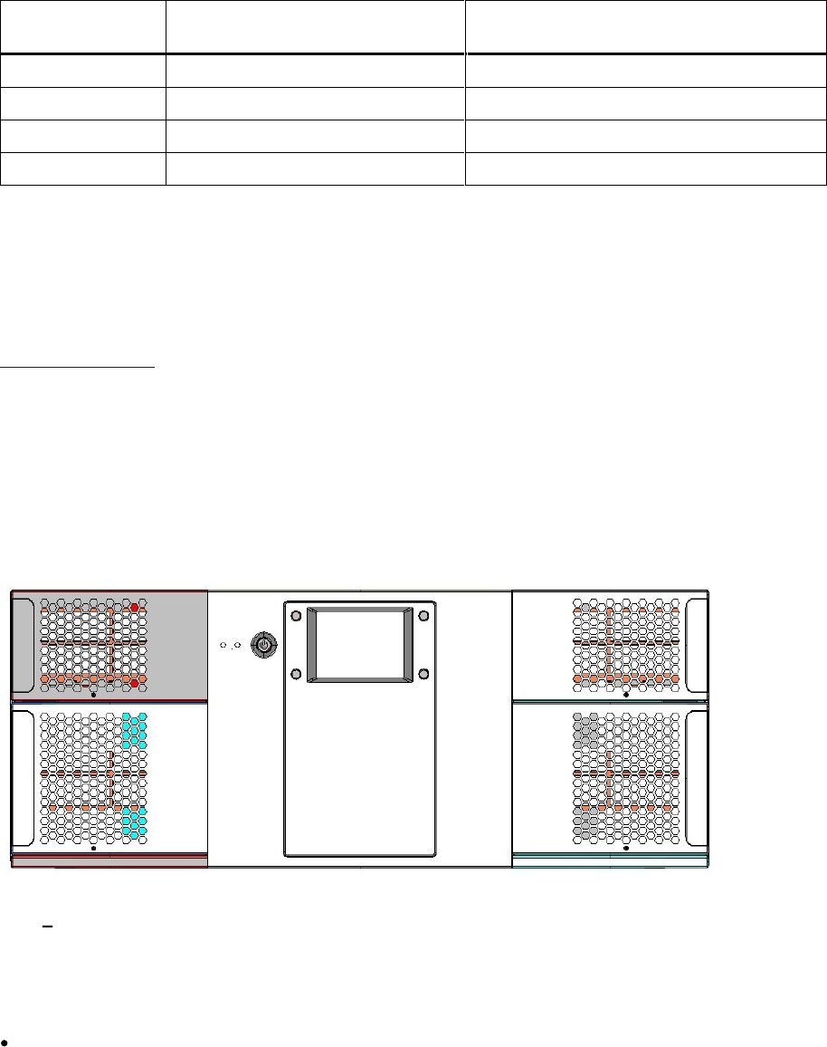
Front Panel
The Front Panel
includes the
Operator
control panel with LCD display, four control buttons, two LED
indicators and a standby switch. The bezels of the four magazines are also visible from the front.
Figure
1.
Front
Panel of t
he
StorageLibrary
LCD
L
iquid
C
rystal
D
isplay
The display is a backlit 12
8
x
68
, dot
-
matrix graphical display that can show 8 lines of 20 characters.
In various modes of operation, the display panel screens and control buttons allow you to do the
following:
Enter settin
gs
for
StorageLibrary
configuration
.
StorageLibrary Installation and User Guide
5
Issue operational commands
.
View
StorageLibrary
status and information
.
Test
StorageLibrary
functionality
.
Control Buttons
The labels for the four control buttons are displayed in the corners of the LCD. All buttons have
soft
function for different modes of operation, i.e. the functions of the buttons change during different
activities. The actual function for each button is always visible on the display.
LED Indicators
The two LED indicators are green and amber. They ind
icate the
StorageLibrary
activity as follows:
Green LED on: The
StorageLibrary
is either
running or ready for operation
.
Green LED blinking: Short blinks followed by long intervals indicate that the library is in low power
standby mode
.
Amber LED on: Faul
t LED; the
StorageLibrary has encountered an e
lectrical or mechanical
failure
.
Standby Switch
A switch on the front panel provides a Library Standby
mode
. If the switch is pushed when the library
is active, the library completes the current operation and t
hen goes offline and enters standby mode.
See
Standby
Functionality
f
or more details.
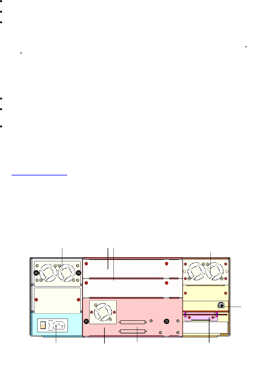
Rear Panel
The figure below shows the rear panel of the
StorageLibrary
.
Figure
2.
Rea
r
Panel of the
StorageLibrary
with 1
Full
-
Height
SCSI
Drive
Installed
Cooling Fans
Forced
-
air cooling fans are integrated in both the power
supply
, the
tape drive,
and behind the
library
control board
. The fans draw air inward throug
h holes in the front bezels and expel it out the back.
The fans start whenever the drive is operating or when the internal temperature in the
StorageLibrary
gets too high.
Main power switch,
power outlet
and fuse
Back panel
cover plate
s
SCSI
connector
s
Emergency eject tool
.
(RTC
battery and
drive
power
extension
cable
behind cover.)
Ethernet
connector
Tape drive
with fan
Power supply
with fans
Cooling fans

6
Product Overview
Main Power Switch/ Fuse/Power
C
ord
C
onnection
The main power switch
is located
at
t
he rear of the library on the power supply bracket. The power
switch, the fuse holder (with a 250V 2A
f
use) and the AC power cord connection are combined in one
common unit.
SCSI and Fiber Channel Interface Connectors
The library supports both SCSI and FC
drives. The SCSI
tape drive
has two shielded 68
-
pin HD SCSI
connectors on the rear panel and the FC
tape drive
has
one
FC connector. The connectors are used
for connecting the tape drive and the
StorageLibrary
to the host. These connectors can link to the
following:
A shielded male HD68 SCSI cable
A shielded male HD68 SCSI terminator
FC port
cable
Ethernet Port
This port is for
networking in support of the Web Client.
It allows
you to connect the StorageLibrary
to
a 10
BaseT
compatible
Ethernet network.
Ba
ttery Holder
The battery for the real time clock is
located
behind a plate at the rear of the library.
A drive power
extension cable is found in the same location.
Back Panel Cover plate
If a drive
bay
is empty
,
a
cover plate
covers the opening to prevent
dust from entering the library.
Library Features
This section describes several features of the
StorageLibrary
.
Operator
Interfaces
The front panel is located on the front of the library and allows
users
to work locally on the library via
the
Operator
inte
rface
(Front Panel Interface, FPI)
. The
Web Client is a
remote management interface
that
allows
users
to view and perform library functions from remote sites and is accessible through a
browser. The front panel
interface and
the Web Client
contain a simila
r
Operator
interface and
functionality. For more information about the front panel and the
Web Client
interface,
see
Information
about
the
Operator
Interfaces
.
ADI Bridging and LUN
The
StorageLibrary
implements
Automation Drive Interface
(
ADI
)
bridging with
Logical Unit
Numbering (LUN
)
addressing. This means that the library controller does not have its own host
interface, but SCSI commands to the library control
ler are sent via one of the installed tape drives.
The tape drive and the library controller will have a common SCSI ID but different LUN numbers. The
SCSI commands to/from the library controller are sent via the tape drive s ADI port.
The purpose of the L
UN interface is to eliminate the requirement for a host interface on the library
controller boa
rd
.

StorageLibrary Installation and User Guide
7
Partitions
Partitions are virtual sections within a library that present the appearance of multiple, separate
libraries for purposes of file management, acce
ss by multiple
Operator
s, or dedication to one or more
host applications.
Organizing the library into partitions divides the resources into virtual sections. If one of the resources
is not available due to a failure or other cause, the other partitions and
their assigned components are
still available.
The
StorageLibrary
can be divided into a maximum of four partitions. At least one tape drive and one
magazine must be assigned to each partition. The robot, the import/export
slots
and the cleaning s
lots
are
common resources to all partitions. For more information on partitions
, see
Configuring
Partitions
.
Control Path
The control path tape drive is used to connect a partition to a host applica
tion. Only one tape drive
can be selected as the control path at one time. By default, the first tape drive assigned to a partition
is designated the control path. In the event that the control path connection to the host application
fails, you can select
a new control path for the partition.
I/E Station
I/E station enables importing and exporting cartridges without interrupting normal library operations.
I/E station
slots
are located in
either the lower left or the upper left
magazine. The number of I/E
sl
ots
for the 40
slot
library is
user
settable to 0 (none), 3 or 8. The number of
I/E
slots
for the 24
slot
library
is
user
settable to 0 (none) or 3.
The I/E
slots
are shared among all partitions. When a
cartridge in a
n I/E
slot
is assigned to a partition,
only that partition can access that
I/E
slot
.
Access to the I/E
slot
is managed through the front panel interface only.
Simple Network Management Protocol (SNMP)
The
StorageLibrary
supports system monitoring via SNMP and SNMP Notifications.
Capacity on Dem
and (COD)
In
StorageLibrar
y
, LTO storage
slots
are licensed for use. At any time, Capacity on Demand (COD)
allows you to enable the unused storage
slots
within a library via a
firmware license key. The
StorageLibrary
comes with 24
slots (two lower magazine
s)
and supports licensing of additional 16
slots (two upper magazines)
.
Details about the COD license key
:
The license key does
not expire
.
Once a license key is installed it cannot be removed
.
Contact Technical Support or open a service request to order a
COD License Key. For contact
information,
see
Getting
More
Information
or
Help
.
To see your library s current configuration and
slot
availability, open
the
home screen
of t
he remote
management interface.
An instruction sheet that describes how to use the license key is provided in the accessory kit.
Once
you receive the license key, enter
it
via the front panel of the library. When the license key is entered,
the total number of avail
able
slots
in the library increases.

8
Product Overview
Browser Requirements
The supported browsers include:
Firefox version 1.0.6
and above
Internet Explorer version 6.0
and above
StorageLibrary Installation and User Guide
9
3 Unpacking the StorageLibrary
This chapter provides detailed information for preparing the library location.
Caution
After the library is unpacke
d it needs to acclimate for 8 hours before the power is
turned on.
Finding a
L
ocation for the
StorageLibrary
The
StorageLibrary
must be positioned in a stable location
.
The
StorageLibrary
is designed to operate in a horizontal position. Do not attempt to
operate the
StorageLibrary
in any ot
her position than horizontally
.
Make sur
e a power source is available
.
Route any cable to avoid walking on them or pinching them with items placed on or against them.
Pay particular attention to the cord at the wall re
ceptacle, and the point where th
e cord exits from
the
StorageLibrary
.
Make sure that object will not fall and liquids will not spill into th
e chassis openings
of the
StorageLibrary
.
Make sure t
he airflow around the front and back of the
StorageLibrary
is n
ot obstructed
.
Make sure t
here is a minimum of 60cm free space in front of the unit to allow the operator
to
safely remove the magazines
.
Make sure t
he display and operator controls can easily be accessed
.
Make sure t
he
StorageLibrary
is away from the floo
r and in a clean environment with
temperatures within specifications. See
Specifications
.
Unpack
Caution
You must remove the
transport locking screws
when powering up the unit for the
first time o
r it will not operate. See the procedure in
section
Remove
the
T
ransport
L
oc
king
Screws
.

10
Unpacking the
StorageLibrary
To unpack the
StorageLibrary
, follow the instructions below.
1.
Carefully unpack the unit
from the shipping container. Save the container and packing materials in
case you need to transport the
StorageLibrary
in the future. The packaging is specifically
designed for the library to ensure it is no
t damaged during transportation.
2.
The
StorageLibra
ry
could be lifted by one person if drives, power supply, and magazines are
removed. However, for absolute safety, it is recommended that two people lift the
StorageLibrary
.
Full library weight = 38 kg / 84 lbs (2 FH drives). Empty library weight = 23.6 kg
/ 52 lbs (does not
include drives, magazines or power supply).
3.
Review the contents of the shipping container to be sure that all parts were included in the
shipment and no parts are damaged. A standard package for the
StorageLibrary
consists of the
follow
ing items:
A factory-
assembled
StorageLibrary
unit conta
ining four cartridge magazines
A
standard accessory kit
containing:
Printed copy of the Quick
Start
Guide
1
Warranty/Registration Information
Rack mounting
kit
including rack mount
ears
2
p
ower
cords
:
one for USA/Japan and one for European power outlets
1 Ethernet cable
Media barcode label kit (contains media labels and cleaning cartridge labels)
There
will be variations of this list.
Depending on the number of drives in your library and whether
or not
your library is equipped with SCSI or FC drives, the accessory kit may contain a terminator
and SCSI cable.
The
StorageLibrary
accessory kit contains no cartridges.
4.
Complete product registration online at
http:/
/www.tandbergdata.com
, Support, Register Your
Product.
StorageLibrary Installation and User Guide
11
4 Installing the Library
This chapter provides detailed information for installing the library hardware. For basic library cabling
instructions, refer to the
Quick
Installation
Guide
.
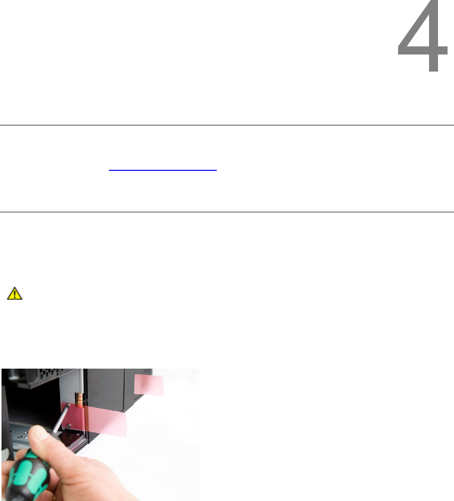
Remove the
T
ransport
L
oc
king Screws
To protect the library during transport
,
four
transport locking screws
hold the robotics in a locked
position. The screws are marked
with red plastic tabs protruding between the magazines and the front
panel.
Caution
The
transport locking screws
must be removed before the
StorageLibrary
can
operate normally.
Figure
3.
Transport
Lock
ing Screws
Marked with R
ed Plastic Tab
s
The
transport
locking screws will be detected when the
StorageLibrary
is powered on. To remove the
screws
follow the instructions below
:
1
Connect the power cord to the power c
onnector on
the
rear of the library
.
2
Turn on the power sw
itch o
n the rear of the library
.
3
The library detects that the transport
locking
screws are present. Follow the instructions on the
front panel display to remove the magazines to get access to the screws. Remove the sc
rews and
reinsert the magazines
.
12
Installing the Library
The library
will now continue its power
-
on sequence.
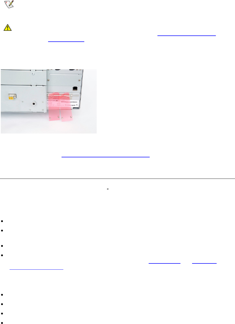
Note
Keep the
transport
locking screws i
n a safe place. You will need them
to lock the
robotics
if you need to return your
StorageLibrary
for service or repair.
Caution
The warranty does not cover
damage to t
he library if transported
without the
transport locking screws properly installed. See
Reinserting
the
Transport
Lock
ing
S
crews
for instructions on how to reinstall the
transport lock
ing screws
.
Figure
4.
Recommended
Storage of Transport Locking Screws
If the library is to be mounted in a rack, this is the time you should mount the
rack mount
ears to the
library. See instructions
in
Mounting
the
StorageLibrary
in
a R
ack
.
Mounting the
StorageLibrary
in a
R
ack
The
StorageLibrary
is designed for use in a 19 rack system using 4U of rack space. The length of the
power c
ord and the primary interface cables
restrict the placement.
The
StorageLibrary
is designed to operate in a horizontal position. Do not attempt to operate the
StorageLibrary
in any other position than horizontally. Also make sure that:
The airflow around
the front and back of
the
StorageLibrary
is not obstructed
.
There is a minimum of 60cm free space in front of the unit to allow the operator
to safely remove
the magazines
.
The display and operator
controls can easily be accessed
.
The
StorageLibrary
is awa
y from the floor and in a clean environment with temperatures within
specifications.
For specifications and safety information, see
Specifications
and
Safety
and
Regulatory
Information
.
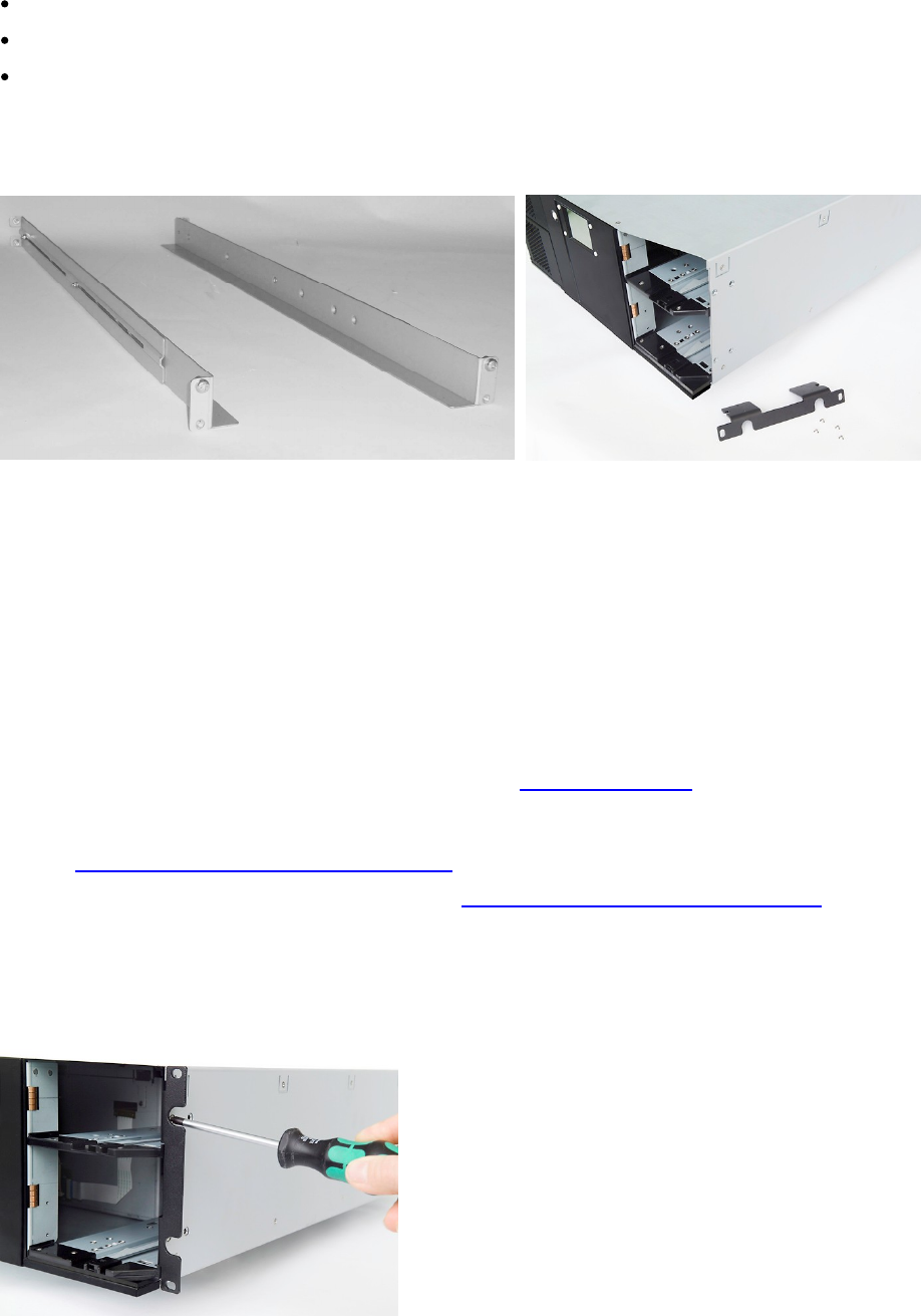
The
Rack mounting
Kit includes the following items:
Rack mount
Ears (2 ears and 8 screws M
3x4
)
Left Rail
Assembly
Right
Rail
Assembly
Screw M6x12 (6 pieces)
StorageLibrary Installation and User Guide
13
Recommended mounting tools
:
Folding rule or tape measure
Screwdriver
7 mm open
-
end wrench
Figure
5.
Rack mounting
Kit with
Rack mount
Ears (
Right
f
igure)
Mounting the
Rack mount
E
ars
To mount the
rack mount
ears
,
the four magazines must be removed. To r
emove the magazines
,
follow the instructions below:
1
Connect the power cord to the power c
onnector on rear of the library
.
2
Turn on the power sw
itch on the rear of the library
.
3
Wait
until
the library
completes its
power
-
on sequence
.
4
Use the front panel inter
face to remove the magazines (
Menu > Operations
> Eject Magazine
).
5
Physically remove
the magazines from the library
, see
Magazine Handling.
6
If your library supports 24 magazine slots
only
, you
need to use the emergency eject tool to
remove the two upper magazines. The emergency eject tool is located at the rear of the library.
See
Manual/Emergency
Release
of
Magazines
7
Mount the ears to the chassis of the library, see
Figure
6.
Mounting
the
Rack
mount
Ears
.
8
Gently reinsert
the magazines into the library
.
Figure
6.
Mounting
the
Rack mount
Ears
14
Installing the Library
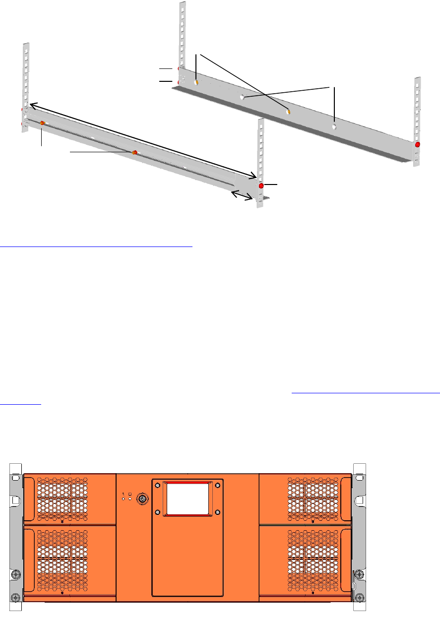
Installing the
Rails
in a Rack
Determine the proper position of the rails in the rack.
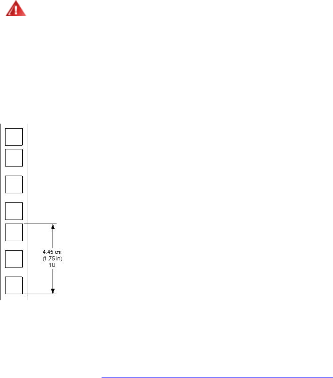
Warning
Consider rack stability when deciding where to place the
StorageLibrary
.
Hazardous conditions can result from un
even mechanical loading of a rack.
The
StorageLibrary
uses 4U of vertical rack space. The rails must be installed in a full U position. The
bottom of the rails must be a
ligned with the bottom of a U.
Figure
7.
Rack mount Rail
I
nstalling the Left Rail Assembly
1
Measure the length between the rear
rack mount
rails and the front
rack mount
rails. If the
measurement is shorter than the
StorageLibrary
,
adjust
the two sets of screws M4x12, washers
,
and nuts shown in
Figure
8.
Mounting
the
Rack
mounting
Kit
to
a
Rack
.
2
Adjust the Left Rail Assembly
to fit the measurement in step 1.
3
Use a
7-
mm open
-
end wrench together with the screwdriver to tighten the
two M4x12 screws to
fix the rail length. Using more than two screws increases the stability of the
Rack mounting
Kit.
4
Place the Left Rail Assembly
on the left side of the rack, between the rear
rack mount
rail and the
front
rack mount
rail.
5
Mount the Left
Rail Assembly
at the desired height using one M6x12 screw in front (upper hole in
rail only) and two M6x12 screws at the backside.
Installing the Right Rail Assembly
Follow the instruction for left s
ide, only using the Right Rail Assembly
on the right si
de of the rack.
StorageLibrary Installation and User Guide
15
Figure
8.
Mounting
the
Rack mounting
Kit to a Rack
Figure
9.
StorageLibrary
Mounted
in
a
Rack
shows the r
ails
mounted in
a
rack with one screw M6x12
in upper hole on both left and right side. On the rear side, two screws must be used on both left and
right side. A total of six screws are used to install the
rails
to the rack.
Mounting the
StorageLibrary
to the Rack
Make sur
e
that the screws connecting the rails to the rack
are tightened properly before installing the
StorageLibrary
in the rack.
Slide the
StorageLibrary
on the rails from the front of the rack
.
Fix the
StorageLibrary
using
two
M6x12 screw
s
in front of the rac
k
, one
on both left and right side.
T
he lower screw on each side connects the library to the rack, whereas the upper screw on each side
connects the left and right rail assemblies
to the rack
, as shown in
Figure
9.
StorageLibrary
Mounted
in
a
Rack
.
Figure
9.
StorageLibrary
Mounted in a
Rack
, Front View
Rear Rack Mount Rail
Step 5
(Screw M6x12)
Step 3
(Screw M4x12,
nut and washer)
Step 2
Step 5
(Screw M6x12)
Front Rack Mount Rail
Step 1
Holes to be used if rack
depth is shorter than the
StorageLibrary T40
Use these holes if
rack depth is equal
or longer than the
StorageLibrary T40
Step 1
16
Installing the Library
Figure
10
.
StorageLibrary
Mounted in a Rack, Rear View
The f
igure above gives a rear
-
end
view of the
StorageLibrary
mounted in a rack. The
two screws on
each side connect
the
left and right rail assemblies to
the rack.
Installing the
L
ibrary
After mounting, you must
connect the
cable
s
to
the library. Two sets of ca
bling instructions are
available:
For
libraries with SCSI tape drives
For libraries
with Fibre Channel tape drives
For instructions on cabling a library with SCSI tape drives,
see
Connecting
Library
Cables
(SCSI).
For instructions on cabling a library with Fibre Channel tape drives,
see
Connecting
Library
Cables
(Fibre
Channel)
.
If your library
includes both SCSI and Fibre Channel tape drives, cable the tape drive following the
appropriate instructions for that tape drive type
.
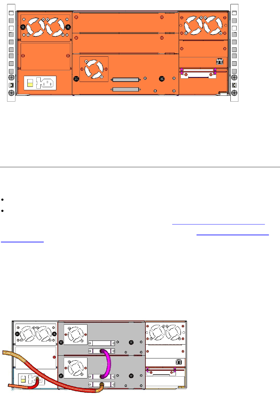
Connecting Library Cables (SCSI)
Use this procedure if you are installing a library that includes SCSI tape drives.
F
igure
11
.
StorageLibrary
C
abling (SCSI)
StorageLibrary Installation and User Guide
17
Guidelines for
C
onnecting the SCSI
C
ables
1
Before the SCSI bus cable is connected to the
StorageLibrary
, make sure the
StorageLibrary
power switch is off.
2
Make sure your host system is in a s
tate where a new SCSI device can be safely connected to the
SCSI bus.
3
Do not exceed SCSI bus length restrictions.
a.
Add the length of all external and internal SCSI cables on the bus
.
b.
Add
26.4 cm (10.
4 inch) for the internal cable length in the
StorageLibr
ary
.
c.
The maximum allowed length of an LVD SCSI bus is 12 m (39 ft) if the number of
SCSI devices exceeds two.
4
Before the
StorageLibrary
is powered on and the system is restarted, make sure the SCSI bus is
properly terminated.
Connecting the
C
ables
1.
Instal
l the library in a rack
or
install
the tabletop
kit
.
2.
Connect the SCSI cables to the
tape drive
.
a.
On the bottom tape drive, connect a jumper cable to the top SCSI connector and then to the
bottom SCSI connector on the tape drive above it. Repeat this step fo
r all tape drives on the
SCSI bus. Secure the cable with the t
h
umbscrews on the connectors.
a.
Terminate the last device on the SCSI bus with the appropriate SCSI terminator.
b.
Connect a cable between the last tape drive on the SCSI bus and the host. Note that
there are limitations to the length of the SCSI cable.
3.
Connect your
Ethernet
cable to the
Ethernet
port on the rear of the library
.
This will give
remote
access to the library via the remote management interface. Push the cable
until
it snaps into
place. C
onnect the other end to a normal 10/100 BaseT Ethernet outlet.
4.
Connect a power cord to the outlet on the power supply on the rear of the library.
5.
Power on the library by t
urning on the rear power switch.
6.
Power up the host system.
7.
Verify communication with
all devices on the bus.
8.
Configure your library using the commands on the front panel. For configuration information, refer
to
Configuring
the
Library
.
Warning
Make sure the AC outle
t that you connect the
StorageLibrary power
cable into is
reliably earthed.
Adding the StorageLibrary
to an existing rack installation can cause a leaking
current fault condition because of the summation of the leaking currents.
For security, a 250V 2A fus
e is located near the power switch
.
Note
Tandberg
recommends that all external SCSI devices, including the
StorageLibrary
, are powered on before the computer system is re
-
started (Steps
5 and 6 above).
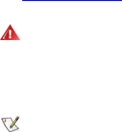
Connecting Library Cables (Fibre Channel)
Use th
is procedure if you are installing a library that includes Fibre Channel tape drives.
18
Installing the Library
Figure
12
.
StorageLibrary Cabling (Fibre Channel)
1.
Install the library in a rack or
install
the tabletop
kit
.
2.
Connect the fibre cables to the
t
ape drive
.
a.
Attach one end of the fibre cable to the fibre port on each
tape drive
.
a.
Attach the other
end of the cable to the host, switch
or hub
.
Note
The fibre cable can be connected from the tape drive to a switch rather than a
host.
3.
Connect your
Et
hernet
cable to the
Ethernet
port on the rear of the library for remote access to the
library via the remote management interface. Push the cable into it snaps into place. Connect the
other end to a normal 10/100 BaseT Ethernet outlet.
4.
Connect a power cord
to the outlet on the power supply on the rear of the library.
5.
Power on the library by t
urning on the rear power switch.
6.
Power up the host system.
7.
Verify communication with all devices on the bus.
8.
Configure your library using the commands on the front pan
el. For configuration information, refer
to
Configuring
the
Library
.
System Power
-on
At power
-
on, for the first few seconds the unit performs a sequence of diagnostic tests called Power
-
On Self Tests (POST). POST also includes a loop
-
back test of the robot
ics
cabling.
After the POST sequence completes successfully, the library will respond to SCSI selections. Then
the system starts a series of initialization functions, a process that co
nsists of robot calibration
operation and cartridge inventory of magazines and drive.
The
barcode labels on the cartridges will be
read when running inventory.
During these operations
,
the library continuously shows the map status on the screen. The status
of
all magazine
slots
and the drives are initially unknown, and a
question mark (?)
is displayed for each
slot
. As the robot searches the magazine
slots
for cartridges during inventory, the display is updated.
Note
The t
ape drive needs up to 60
seconds
after
power
-
on until
it is
active on the
SCSI bus. You should turn on the power at least
60
seconds before the computer
system is started.
StorageLibrary Installation and User Guide
19
Note
If the self
-
diagnostics and the inventory sequence are successfully completed,
the green LED illuminates an
d the display returns to the home screen. The library
is now ready for further configuration and operation.
If a problem occurs during the power
-
on sequence, the
StorageLibrary
displays an error message on
the display. Refer to
Troubleshooting
to learn the procedures for resolving the problem.
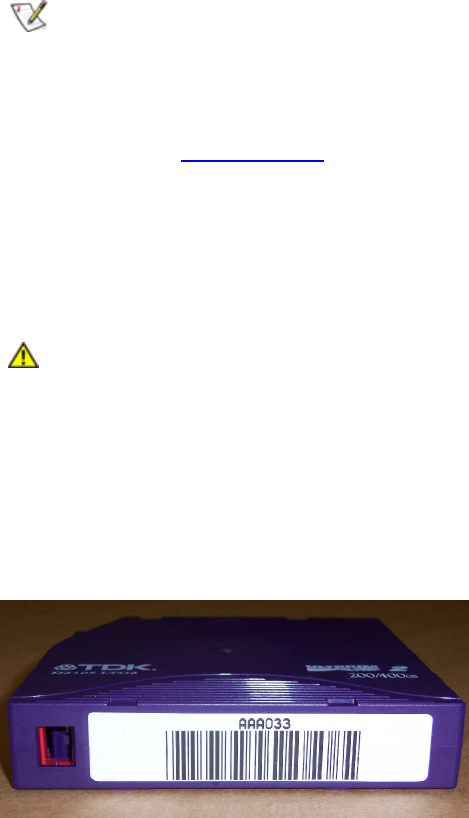
Labeling Cartridges for the Barcode Reader
Y
ou must attach b
arcode labels to the cartridges if you want to use the barcode reader functionality in
the libr
ary.
Caution
You must use
StorageLibrary
-
specific barcode labels to ensure reliable
functionality of the barcode reader.
Cartridge labels must be oriented on the cartridges as shown in the figure below with the locking
mechanism to the left.
Figure
13
.
Positioning of B
arcode
Label for LTO C
artridges

StorageLibrary Installation and User Guide
21
5 Information about the Operator Interfaces
The
StorageLibrary
has two
Operator
interfaces: the Front Panel Interface (FPI) and the Remote
Management
Interface (RMI). Operations on the
StorageLibrary
can be performed locally on the
library using the FPI or remotely on your computer using the remote management interface (RMI).
Similar functionality with common elements is used for both formats.
Note
Both
Front Panel Interface and the R
emote Management Interface are required
to
access all options for operating
the library. Some functionality is only available
through the remote management interface, and some functionality is only
available through the
front panel interface. However, it is recommended that you
use the remote management interface rather than the front panel to perform
library operations whenever possible.
Front Panel Interface (FPI)
The front panel is physically attached to the front of
the library.
The
Operator
interface appears on the
LCD display of the front panel for executing basic library management functions.
The functions of the four control buttons are displayed in the corners of the LCD. The functions of the
buttons change durin
g different activities, and the actual function for each button is always visible on
the display.
The Front Panel includes the
Operator
control panel with LCD display, four control buttons, two LED
indicators and a standby switch.
Scroll Function
The front
panel display is able to
display
20
characters in a line. Some
functionality requires more
than 20
characters.
To access
all
characters a scroll function is implemented.
The buttons on the front
panel are used
to scroll
the text
left or right (a left arro
w appears on the left button and a right arrow
appears on the right button to indicate the scroll function).
T
he number of lines on the display is limited. If the text to be displayed contains more than 8
lines
,
a
similar scroll function as described above
is used.
For line scrolling,
the arrows on the buttons indicate
scroll up or down function.

22
Information about the
Operator
Interfaces
Remote Management Interface
The remote management interface is similar to the front panel interface. The remote management
interface is accessible from any support
ed web browser. For more information on supported web
browsers, refer to
Browser
Requirements
. To manage the library from a remote management
interface, you must set up the library s initial netwo
rk configuration from the front panel. For
information on network configuration settings for remote use, refer to
Configuring
Network
Settings
.
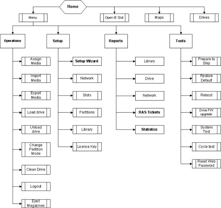
Menu Trees
The following four menus o
rganize commands into logical groupings:
The Operations menu consists of commands that enable you to change the library s mode of
operations, import and export cartridges, load and unload tape drives, eject magazines, clean
drive and change partition mode.
The Setup menu consists of commands that you can use to set up and configure various aspects
of the library, including network, partitions, I
/
E stations, cleaning
slots
, drive configuration, license,
password, menu timeout, date and time, barcode scan, an
d audible alarm.
The Reports menu consists of summaries of the values assigned during library setup. It also
includes viewing of RAS tickets and diagnostic logs.
The Tools menu consists of commands that you can use to maintain your library such as restore
default settings, reboot, prepare for shipping,
update
firmware, and run system tests.
Figure
14
Front
Panel
Interface
Menu
Tree and
Fig
ure
15
Remote
M
anagement
Interface
Top
Level
Menu
Tree
give an overview of the menus on the front panel
and the remote management interface.
Table
2.
Front
Panel
Interface
Menu
Structure
and
Table
3.
Remote
Management
Interface
Menu
Structure
describe
t
he
same menu
s
but with more details
.
StorageLibrary Installation and User Guide
23
Figure
14
Front Panel Interface Menu Tree

24
Information about the
Operator
Interfaces
Table
2.
Front Panel Interface Menu
Structure
Operations
Setup Reports
Tools
Assign Media
Setup Wizard
Network
+ IP Address Mode
+ Stati
c IP Address
+ Static Netmask
+ Static Gateway
+ Allow Web Access
+ Allow Web FW Upg.
Slots
+ License Key
+ IE Slots
+ Cleaning Slots
Partitions
+ Partition Assignment
(Drives & Magazines)
+ Drive Interface ID
+ Control Path
+ Autoclean
+ Barcode Mode
Libr
ary
+ Password
+ Inquiry String
+ Menu Timeout
+ Barcode Scanner
+ Date and Time
+ Audible Alarm
Library
>
Slots and Drives
>
Inquiry String
>
FW Version
>
Barcode
Scanner
>
Audible Alarm
>
Serial Number
>
Date
and
Time
> Autoclean
> Barcode Mode
> Menu
Timeout
> World Wide Name
Prepare to Ship
Import Media
Network
+
IP Address
Mode
+
Static IP Address
+
Static Netmask
+
Static Gateway
+
Allow
Web Access
+
Allow Web FW Upg.
Drive
>
Interface ID
>
Inquiry String
>
FW Version
>
Serial Number
>
World Wide
Name
>
Control Path
Restore Default
Table
continued on next page.

StorageLibrary Installation and User Guide
25
Operations
Setup Reports
Tools
Export Media
Slots
+ IE Slots
+ Cleaning Slots
+ Partition Assignment
(Drives & Magazines)
+ Drive Interface ID
+ Control Path
+ Autoclean
+ Barcode Mode
Network
>
Library Name
>
IP Address Mode
>
Static IP Address
>
Static
Netm
ask
>
Static Gateway
>
Dyn
amic
IP Address
>
Dynamic Netmask
>
Dyn
amic
Gateway
>
MAC Address
>
Allow
Web Access
>
Allow Web FW Upg.
Reboot
Load Drive
Partitions
+ Partition Assignmen
t
(Drives & Magazines)
+ Drive Interface ID
+ Control Path
+ Autoclean
+ Barcode Mode
RAS Tickets
Drive FW Upgrade
Unload Drive
Library
>
Password
> Inquiry String
> Menu Timeout
> Barcode Scanner
> Date and Time
>
Audible Alarm
Statistics
> Fetch/Stow
>
Power On Time
>
Drive Cleaning
System Test
Change Partition
Mode
License Key
Cycle test
Clean Drive
Reset Web Password
Logout
Eject Magazines
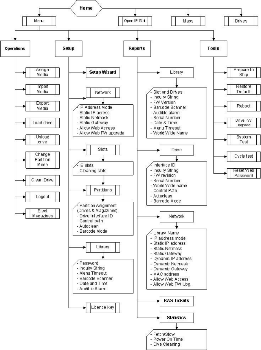
26
Information about the
Operator
Interfaces
Fig
ure
15
Remote M
anagement Interface Top Level Menu Tree

StorageLibrary Installation and User Guide
27
Table
3.
Remote Management Interface Menu
Structure
Operations
Setup Reports
Tools
Assign Media
Setup Wizard
+ License Key
Slots
+ IE Slots
+ Cleaning Slots
Partitions
+ Partition Assignment
(Drives & Magazines)
+ Drive Interface ID
+ Contro
l Path
+ Autoclean
+ Barcode Mode
Library
+ Inquiry String
+ Password
+ Menu Timeout
+ Barcode Scanner
+ Date and Time
+ Audible Alarm
Library
+ Inquiry String
+ FW Version
+ Serial Number
+ Password
+ Menu Timeout
+ Barcode Scanner
+ Date and Time
+ Aud
ible Alarm
+ World Wide Name
Maintenance
+ Library FW Upgrade
+ Reboot Library
+ Restore Defaults
+ Identify Library
Import Media
Network
+ Static/Dynamic Mode
+ Static IP Address
+ Static Netmask
+ Static Gateway
Partitions
+ Drive Vendor
+ Drive Inquiry
String
+ Drive Serial Number
+ Drive FW Version
+ Interface ID
+ Control Path
+ World Wide Name
Diagnostics
+ Capture Logs
+ System Test
+ Cycle Test
Table
continued on next page.

28
Information about the
Operator
Interfaces
Operations
Setup Reports
Tools
Export Media
Slots
+ IE Slots
+ Cleaning
Slots
+ Partition Assignment
(Drives & Magazines)
+ Drive Interface ID
+ Control Path
+ Autoclean
+ Barcode Mode
Network
+ IP Address Mode
+ Static IP Address
+ Static Netmask
+ Static Gateway
+ Dynamic IP Address
+ Dynamic Netmask
+ Dynamic Gateway
+ MAC
Address
+ Notification Status
+ Notification E
-
mail Address
+ Notification SMTP Server
+ Notification Severity
Threshold
+ SNMP Trap Host
Load Drive
Partitions
+ Partition Assignment
(Drives & Magazines)
+ Drive Interface ID
+ Control Path
+ Autoclean
+ Barcode Mode
RAS Tickets
Unload Drive
Library
+ Inquiry String
+ Local Password
+ Menu Timeout
+ Barcode Scanner
+ Date and Time
+ Audible Alarm
Statistics
+
Fetch/Stow
+ Power On Time
+ Drive Cleaning
Partition Mode
License Key
Clean Drive
Noti
fication
Web Password
Home Screen
The
remote management
home screen
is
shown in
Figure
16
.
RMI
H
ome
S
creen
.
Use the pull down
menus to
navigate in the RMI
menu
. Click on the grap
hics to display status information and details
about the library components.
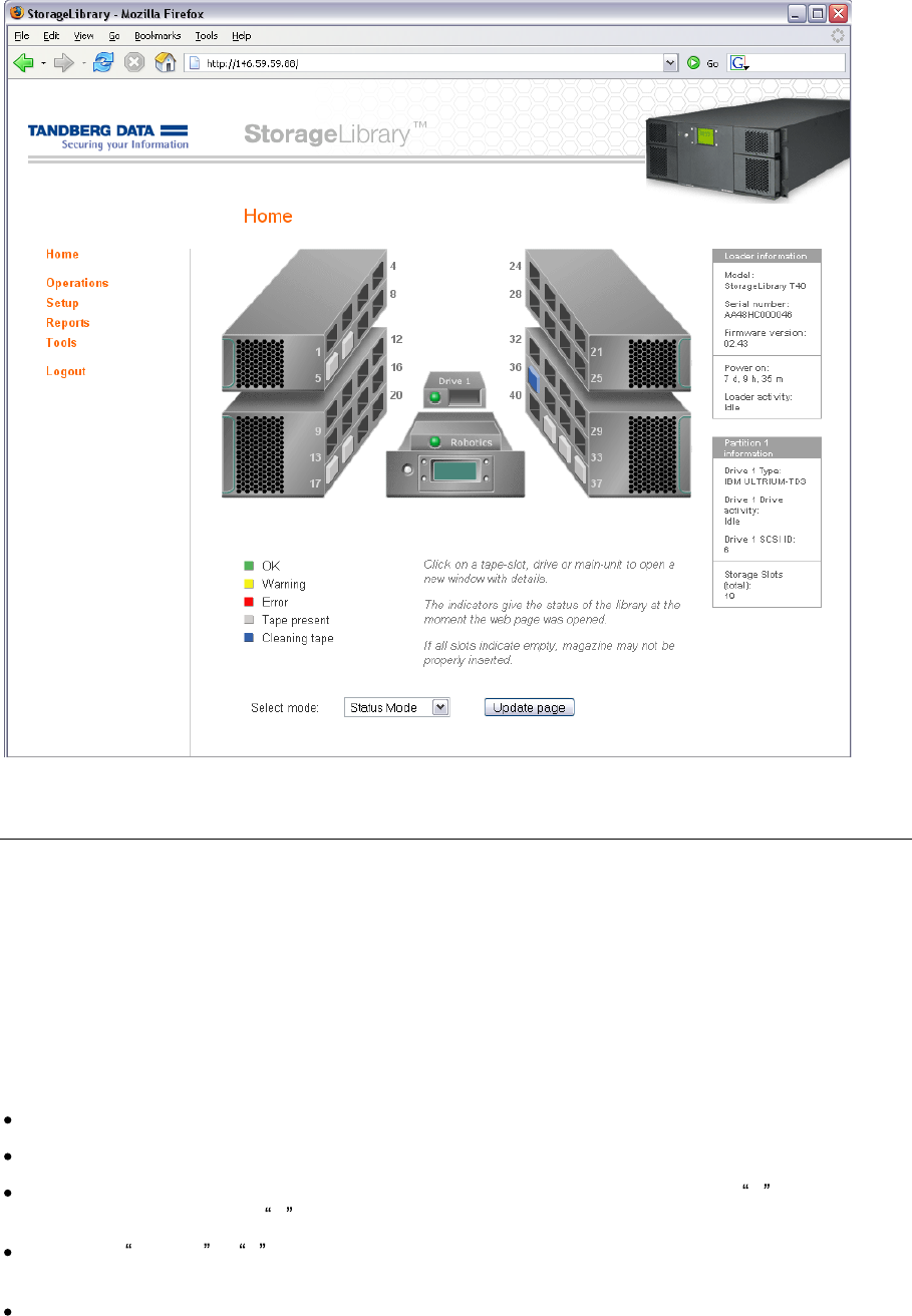
StorageLibrary Installation and User Guide
29
Figure
16
.
RMI H
ome
S
creen
Operator
Privileges
Controlling access to screens and operations within the library preserves the integrity of the library
an
d the data that is stored within the library.
There are two levels of
user
privilege levels within the
library:
Administrator
and
Operator
.
1.
Administr
at
or
is allowed access to the entire physical library and all of its partitions.
2.
Operator
has access to al
l partitions and can perform functions within partitions, such as
performing cartridge and tape drive operations.
An o
perator
cannot perform operations that affect
the physical library, such as creating or deleting partitions.
Details on
user
privileges in
clude:
One administrative login is available on the library. The user name is Administrator
.
One operator login is available on the lib
rary. The user name is Operator
.
Any
o
perator
or
a
dministrat
ive
user
who is
logged in and
inactive for more than
N
minu
tes
is
automatically logged out.
N
is user
configurable
from 1 to 9 minutes
.
Selecting
Log Out or X
in the top right corner of the remote management interface closes the
application and
log
s
the
Operator
and
Administrator
out
.
Only one
user
can be lo
gged in at one time from either the front panel or
the remote management
interface
.

30
Information about the
Operator
Interfaces
Words Commonly Used on the FPI and RMI
Some of the words displayed
on the FPI and RMI screens may need an explanation.
Table
4.
Commonly Used W
ord
s
on FPI and RMI
Word
Abbr.
i
n
FPI
Description
Idle
The library is idle
.
Drive Empty
__
There is no cartridge in the drive.
Drive Loaded
ld
A cartridge is loaded in the drive
.
Drive Idle
ie
A cartridge is loaded and the drive is ready to use it.
Drive
Rewinding
rw
The drive is rewinding the tape
.
Drive Seeking
sk
The drive is searching for specific data on the tape.
Drive Reading
rd
The drive is reading data for transfer to a host via the SCSI interface.
Drive Writing
wr
The drive is writing data rec
eived from a host to the tape.
Drive Erasing
er
The drive is erasing data from parts of or the whole of the tape.
Drive Cleaning
cl
A cleaning tape has been inserted into the drive, and the drive is using
it to clean the relevant mechanical parts.
Drive
Loading
ld
A tape has been inserted into the drive. The drive is in the process of
mechanically loading the tape.
Drive Unloading
ul
The drive is in the process of mechanically unloading the tape.
Drive Update
Ready
ur
The drive has completed an interna
l update.
Drive Updating
ud
The drive is in the process of an internal firmware update.
Drive
Calibrating
ca
A data tape has been inserted and loaded into the drive. The drive is
in the process of measuring its physical properties.
During inventory
and
in the Maps menu
,
different
s
ymbols are displayed on the FPI to indicate
if there
are cartridges present in the magazines, in
the drives
,
and in the robotics
, as show in
Table
5.
Cartridge
Present
Symbols
on
FPI
during
I
nventory
and
in
the
Maps
Menu
.
Table
5.
Cartridge Present Symbols
on FPI
during
I
nventory
and in the Maps Menu
Symbol on FPI
Descri
ption
__
Drive Present, load status empty
??
Drive present, load status unknown
**
Drive not installed
Symbols for the magazine slots and the robotics
Symbol
Description
Grey box if m
agazine slot/robotics status is unknow
n
Filled box
if
c
artridge is present in the magazine slot/the robotics
Empty box if cleaning cartridge is present in the maga
z
in
e
slot
N
The magazine slot/the robotics is empty
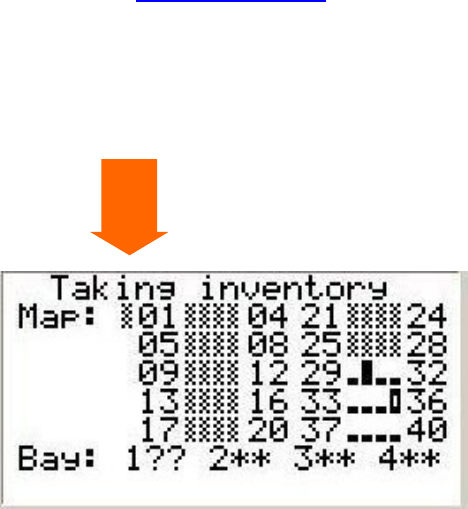
StorageLibrary Installation and User Guide
31
The robotics status is displayed in the Map
menu as the first field after
the word
Map.
(See arrow)
In
the example in
Figure
17
.
Map
Menu
the library is taking inventory. The robotics status is unknown
(grey).
Slot
30 is
full. Slot
36
has a cleaning cartridge
. Slot
s
29, 31 to 35, and 37 to 40,
are empty.
The
status of the
re
st of the slots is
unknown
.
One drive is installed in lowest position, load status still
unknown.
Figure
17
.
Map Menu
Robotics
Status

Stor
ageLibrary Installation and User Guide
33
6 Configuring the Library
After you have installed the hardware described in Setting up the Library Hardware, you are ready to
configure your library s settings. A Setup Wizard helps you get started configuring your library, and the
menu com
mands on both the front panel interface and the remote management interface allow you to
reconfigure your library at any time.
About the Setup Wizard
When you first power on the library, the front panel interface displays the Setup Wizard, which walks
you
through the initial configuration of the library's operational settings, including network settings that
enable you to access the library from the remote management interface. You must begin the Setup
Wizard on the front panel, but you have the option to c
omplete the Setup Wizard on the remote
management interface.
The Setup Wizard prompts you to enter the network settings that allow the remote management
interface to access the library. Once this step is complete, you must choose to either complete the
wiz
ard locally (on the front panel) or remotely (on the remote management interface).
Configuring the library is not a one
-
time process. The Setup Wizard is simply an aid to assist you with
the initial configuration. You can always return to the Setup Wizard
or use commands on the Setup
menu to modify all library settings, including network settings
.
Note
Power cycling (powering the library on and off) is not necessary to configure the
library.
Using the Default
Administra
tive
User
Account (Administrator
)
When you power on the library for the first time, you do not need to log in to use the front panel. You
can start using the Setup Wizard immediately.
When the library is powered ON for the first time, the
password protection to the FPI is disabled. As long
as there is no FPI password enabled, regardless
of how many times the system is restarted, the library will have this free access .
Once you
enable the FPI password,
you
always need the password to access the FPI
.
A User Name and password is always req
uired to access the system via the Web client
.
It is not
possible to access the library remotely without entering a password. The library ships with a default
administrative user account for the RMI.
When you see the Login screen on the remote management
i
nterface, type
the default information of
Administrator
in the
User
Name
field
and
leave
the
Password field
blank
.
The user name and password are
case
-
sensitive.

34
Configuring the Library
Note
You cannot delete the default
Administrator
account. You can, however, change
the pass
word.
Using the Setup Wizard
The Setup Wizard simplifies the process of configuring the library. When you first power on the library,
the front panel displays the Setup Wizard. As you work through the Setup Wizard screens, follow the
on
-
screen instruction
s.
The recommended procedure for using the Setup Wizard for the initial configuration is as follows:
1.
Turn on the library and begin the Setup Wizard on the front panel. Be sure to configure network
settings.
2.
When the
Setup Wizard
screen text prompts you to
choose Local or Remote, you must
choose to
complete the wizard either locally on the front panel interface or remotely on the remote
management interface.
3.
If you choose to complete the wizard remotely, you
must log in
to the remote management
interface. Us
e the default
Administrator
account.
The default User Name is
Administrator
, and
the default
pa
ssword
field
is
blank
.
4.
Complete the Setup Wizard.
Details on using the Setup Wizard include:
You may choose to use the default settings that the Setup Wizard su
ggests, but you must confirm
the proposed settings and complete the Setup Wizard before you can begin using the library.
If you choose to complete the Setup Wizard remotely, the FPI wizard automatically displays the
Network settings you need to access the
RMI.
If you
run the Setup Wizard from
the
FPI and you
do not complete all the Setup Wizard screens,
the library will save whatever modifi
cations (if any) you have made. However if you run the Setup
Wizard from
the
RMI
,
you need to confirm that you want to
save the setup.
You do
not need to log in to the library
from the FPI
when the Setup Wizard appears on the front
panel the first time the library is powered on.
When you power
-
on your library for the first time, y
ou can only configure network se
ttings on t
he
front panel, and y
ou cannot log in to the library from the remote management interface until you
have configured network settings.
You can always return to the Setup Wizard whenever you are logged in
as Administrator
to either
the front panel or the rem
ote management interface.
Note
The setup wizard may need to reboot your library one or more times during setup
Setup Wizard Tasks
The Setup Wizard contains all configuration options. When you first power on the library you must
complete the Setup Wizar
d. When you later want to reconfigure the library you can choose to either
use the Setup Wizard or the individual configuration options found in the Setup menus.
This section includes an overview of the Setup Wizard configurations. The configurations are
d
escribed in detail in the following chapters.
Note
You may not see all the choices presented below when running the FPI Setup
Wizard. It routes you past choices that have become irrelevant because of
previous selections.
Example: If you select RMI DHCP
mode, the Static IP address, netmask and
default gateway are irrelevant.

Stor
ageLibrary Installation and User Guide
35
Welcome
-
W
elcomes you to the Setup Wizard
.
Configuring Network Settings (
FPI)
-
Allows you to enter your net
work settings for remote access
.
Choosing the Interface: Local or Remot
e (
FPI
)
-
Allows you to choose to continue on the front
panel or on the remote management interface. If you choose Local, the wizard proceeds on the
front panel. If you choose Remote,
the FPI presents a Refresh button that needs to be
selected
until the Ne
twork Setting appears
. Exit the front panel, log in to the remote management interface
using the Network Setting
, and select Setup Wizard to resu
me configuring your library
.
Applying a License Key (
FPI
and
RMI)
-
Allows you to enter a
numeric code (License
Key)
for
capacity on
demand
.
Configuring I/E
Slots
(
FPI
and
RMI)
-
Allows you to configure
the number of
Import/Export (I/E)
slots
.
Configuring Cleaning
Slots
(
FPI and RMI
)
-
Allows you to configure
the number of
dedicated
cleaning
slots
to be us
ed throug
h the host application
.
Configuring Partitions (FPI and RMI
)
-
Allows you to select the number of partitions
and the drives
and magazines assigned to each partition
.
Setting Tape Drive ID (FPI and RMI
)
Allows you to configure the SCSI ID of the SCSI driv
es
if
your library includes SCSI drives
. If your library includes fiber
channel drives the FC
node name
and port name appear
.
Modifying Control Path (
FPI and RMI
)
-
Allows you to configure which drive shall be the control
path in
each of the
partition
s.
Mo
difying Library Inquiry String (
FPI and RMI
)
-
Allows you to configure the inquiry string for the
library
.
Configuring Autoclean (
FPI and RMI
)
-
Allows you to enable/disable automatic drive cleaning
.
Configuring Password (FPI and RMI
)
-
Allows you to s
et p
assword on the FPI
.
Configuring Menu Timeout (
FPI and RMI
)
-
Allows you to configure the timeout delay on the front
panel and RMI menu
s.
Setting Date and Time (
FPI and RMI
)
-
Allows you to set the date and time on your library (set the
real time clock)
.
Co
nfiguring Barcode Scan (
FPI and RMI
)
-
Allows you to enable/disable the barcode reader
.
Configuring Audible Alarm (
FPI and RMI
)
-
Allows you to enable/disable the audible alarm
.
Confirm Settings (
FPI and RMI
)
-
Allows you t
o confirm your library settings
.
Note
Configure the date and time of the library from the
Setup
menu immediately
following initial configuration of the library using the Setup Wizard.
The front panel displays the Setup Wizard the first time you power on. After that,
you can log in as
Administrator to access the Setup Wizard
.
The paths to open the appropriate screen are:
From the
RMI
, select
Setup >
Setup Wizard
From the
FPI
, select
Setup > Setup Wizard
Configuring Network Settings
The Network configuration screen provides information
on the network settings that are configurable
from the front panel. The network settings include:
D
ynamic or static IP address

36
Configuring the Library
Static
IP address
Static d
efault gateway
S
tatic s
ubnet mask
Enable/disable RMI interface
Enable/disable RMI FW upgrade
Use the Ne
twork configuration screen to configure the library network settings. The network settings
set the connectivity of the library to the network.
If Dynamic Host Configuration Protocol (DHCP) is enabled on your network, enabling DHCP will
automatically config
ure the library network settings. If DHCP is not enabled on your network, you
need to manually configure the IP address, subnet mask, and default gateway settings.
Details on network settings include:
The library can be set to DHCP mode, or the IP address,
subnet mask, and default gateway must
be configured. DHCP is selected by defa
ul
t.
The IP Address, Default Gateway, and Subnet Mask text boxes are limited to numeric characters
.
Each of the four groups
cannot
have a value greater than 255
.
The paths to ope
n the appropriate screens are:
From the
RMI
select
Setup > Network
After the initial setup of your library you can access the Network configuration screens directly
from
both
the FPI and the
RMI
:
From
the RMI
, select
Setup > Network
From the FPI
, select
Se
tup > Network
Remote Access
If you choose to complete the Setup Wizard remotely, the FPI wizard automatically displays the
Network settings you need to access the RMI.
The network
settings are
also viewable from the
front panel
Reports >
Remote Management
Info
screen
. The screen
provides the information necessary to access the remote management interface.
The screen lists the IP address of the library. Use this IP address to access the remote management
interface using a web browser. When typing the IP addr
ess into a web browser, make sure to precede
it with http:// (for example,
http://123.123.123.123
).
Applying a License Key
A license key
can be purchased and
applied to the library to increase the number of availab
le
slots
from 24 to 40
. The license key is applied during the initial configuration of the library or at any time in
the future.
An instruction sheet that describes how to use the license key is provided in the accessory kit.
Contact Technical Support for more information on obtaining a license key. For contact information,
see
Getting
More
Information
or
Help
.
Note
The license key
is made up of to 5 printable
characters. The licens
e key
is
case
-
sensitive.
The
license
key is verified when it is applied to the library.
It cannot be transferred to another library.
The license key can be entered when running the Setup Wizard.
After the initial se
tup of your library
you can later
acces
s the Activate License configuration screens directly:

Stor
ageLibrary Installation and User Guide
37
From the
RMI
, select
Setup >
License
Key
From the
FPI
, select
Setup
>
Activate License
The library reboots after three failed activation attempts.
Configuring
I/E
Slot
s
I/E
slot
s are used to import and
export tape cartridges into and out of the library without disrupting
normal library operations.
The
24
-
slot
version of the
StorageLibrary
can be configured to have 0 or 3
I/E
slot
s, and the
40
-
slot
version can be configured to have 0, 3
,
or 8
I/E
slot
s.
A library configured with 3
I/E
slot
s will have the
I/E
slot
s located in the
front of
the
lower left magazine.
In a library configured with 8
I/E
slot
s, the
entire upper left magazine will be used as an
I/E
station.
I/E slots are shared by all partitions within a library.
Before you change the
number of
I/E
slot
s, it is recommended that
you r
emove
any cartridges
from
the
slots that will become
the new
I/E
slot
s. If the new
I/E
setting specifies 3
I/E
slot
s,
the number of
slot
s in the partition owning the lower left magazine will be decreased
by 3
.
If the new
I/E
setting
specifies 8
I/E
slot
s,
the partition owning the upper left magazine will lose all 8
slot
s
in this magazine.
Any cartridges left in the new
I/E
slot
s will become unassigned.
When changing
the number of
I/E
slot
s
from 3 to 0 or 8, the 3 front
slot
s in the lower left magazine will
automatically be assigned to the same partition as the rest of the
slot
s
in this magazine.
When changing
the number of
I/E
slot
s
from 8 to 0 or
3
, the entire upper left magazine will
automatically
be
assigned to one of the existing
partition
s
, as determine
d by the original partition
configuration
.
When the
I/E
setup is changed
,
it is
highly
recommended that the partition setup also be
redone.
To identify how the
I/E
magazine is configured, view the
Partitions
report available from the
Reports
menu.
The
I/E
slot
s are configured
while running
the Setup Wizard.
After the initial se
tup of your library
,
you
can later
access the
I/E
Station configuration screens directly:
From the
RMI
, select
Setup >
Slot
s
From the
FPI
, select
Setup >
Slot
s
Configuring Cleaning
Sl
ot
s
The Setup Wizard Cleaning Slot Configuration screen prompts you to enter the number of cleaning
slot
s (if any) you want to designate for your library. You can also access the Cleaning Slot
Configuration screens directly
from
the front panel and remote
management interface.
The Cleaning Slot configuration screen provides information on configuring dedicated cleaning
slot
s,
which are used to store cleaning cartridges that the library uses to clean tape drives. These dedicated
cleaning
slot
s are not visible to the host application.
Configuring one or more dedicated cleaning
slot
s is required to enable the library's cleaning feature.
The libra
ry supports 0
-
3 cleaning
slot
s.
These are located in the three innermos
t
slot
s
(innermost
column)
of the lower right
magazine.
If the library has been previously configured, the number of cleaning
slot
s that
are
currently
co
nfigured appear
s
on the screen.
Cleaning slots are shared by all partitions within a library. Each
partition can use a cleaning slot to manually clea
n its tape drive(s).
Caution
Configuring I/E slots with car
tridges already loaded compromises data security.
First remove cartridges from the I/E slots and then configure the I/E slots.

38
Configuring the Library
Caution
Make sure the
library
has
empty
slots available
in the cleaning slot magazine
before you
add more cleaning slots.
These are located in the three innermost
slots (innermost column) of the lower right magazine.
When
the numb
er of cleaning slots is
increased, the added slots are taken from the partition owning
the lower right magazine. The number of available slots in the affected partition is decreased
by
the
same number
.
When the number of cleaning slots is decreased, the re
leased slots are added to the partition owning
the lower right magazine. Make sure to remove the cleaning cartridges from the library before you
reduce the number of cleaning slots.
The
cleaning slots are configured
with the Setup
Wizard.
After the initial
setup of your library you can
later
access the cleaning slot configuration screens directly:
From the
RMI
, select
Setup >
Slots
From the
FPI
, select
Setup >
Slot
s
Configuring Partitions
Partitions are virtual sections within a library that present the app
earance of multiple, separate
libraries for purposes of file management, access by multiple
users
, or dedication to one or more host
applications. By default, the library has
one partition, which includes
all of the library s resources.
Administrator can c
reate and delete all partitions.
The partitions are generated manually one at a
time. You can create partitions on either the front panel or the remote management interface.
Operator has access to all partitions but cannot create or delete partitions.
At m
inimum, a partition consists of one tape drive and one magazine. The tape drive or slot cannot be
shared with another partition (an exception to the sharing restrictions are cleaning tapes
and the
I/E
s
tation slots
, which
are
shared among all partitions).
You can later change your partition setup either from the front panel interface or the remote
management interface.
Creating Partitions
Use the front panel or remote management interface to create partitions. The maximum number of
partitions that can be c
reated depends on how many drives are installed (up to 4). The
Administrator
must define at least one partition.
To define P
artition 1, the user will
be
asked to select the drive(s)
that shall be
associated with the
partition.
The user will also be asked t
o
select which available magazines to include
in the partition
. Depending
on the selections for
I/E
and cleaning slots, the number of slots for some magazines may be affected.
The wizard displays the number of slots associated with each magazine based on
the input for
I/E
and cleaning so that
it is visible to the operator.
For each partition
, the
user
is
asked
to verify, or change, the SCSI ID and Control Path,
to specify
whether he wants Autoclean enabled or disabled
,
and
to specify
the Barcode Reporting
mode (6
character
s
or 13 character
s
).
If there is at least one unassigned drive and one unassigned magazine, the wizard ask
s
if the
user
wants to configure another partition. If yes, then repeat the steps for partition setup. If no
, the user
gets a warnin
g that there are unass
igned resources in the library.
The
partitions are configured
with the Setup
Wizard.
If you later want to change your partition
configuration, you can either re
-
run the Setup Wizard or
access the partition configuration screens
direct
ly:
From the
RMI
, select
Setup > Partition
/Drive

Stor
ageLibrary Installation and User Guide
39
From the
FPI
, select
Setup > Partition
s
Reconfigure
Partition
s
You may later need to reconfigure your partition setup if
the number of cleaning slots or I/E slot
configuration are changed
, or if you need to
split the library into more or fewer partitions
.
Note
Exporting all cartridges assigned to the partition
s
that
are to be reconfigured
is
recommended
.
It is not possible to edit your partition setup.
If you choose to reconfigure
your partition setup fr
om the
front panel interface, the old setup will be deleted.
If you choose to reconfigure your partition setup from the remote management interface
and your
current partition configuration has used all available resources
, you will need to remove at least
one
partition. The resources from the deleted partition(s) can then be allocated to the remaining
partition(s).
Th
e appropriate screens to reconfigure
your partition setup are:
From the
RMI
, select
Setup > Partition
/Drive
Use the next button in the setup to move to the last partition. Use the remove partition button to
remove the partition. Remove as many partitions you want to, and then allocate the
drives/magazines from the deleted partitions to
the remaining or new partitions
.
From the
FPI
, select
Se
tup > Partition
Changing Partition Modes
The library ha
s two partition modes, Online and
Offline.
Note
When changing the partition mode from online to offline, all host application
commands are completed if they are in progress when the mode is changed
.
Online
the normal operating condition for the partition
. In this mode, the robotics is
enabled and
all host app
lication commands are processed.
Offline
the partition does not process any host application commands. If a partition is taken
offline, t
he physical library and other partiti
ons are not affected.
The library is automatically taken offline when the unit is busy executing internal time consuming
tasks.
In addition the user can manually take the
physical library or any of its partitions online
or offline. You
can take a partition offline rather than the entire library so as to minimize disruption of library
operations. You
may
manually change the partition mode to online or offline from the front panel or
the remote management interface.
Detail
s on changing partition mode include:
The d
efault partition mode is online
.
The partition mode must be set to off
-
line if you want to
restrict host ac
cess to the specified
partition
.
When you are changing partition mode, be aware of the following informati
on:
The Online/Offline
buttons toggles between states
.
It is only possible to set a partition o
ffline
when the partition is not in use
.
Set the button to read Online to take either the physical library or a partition, depending on the
current view, to an online state, which is the normal operating condition
. In this mode, the robotics
is
enabled and
all host commands are processed
.

40
Configuring the Library
Set the button to read Offline to take either the physical library or a partition, depending on the
current view, to an offlin
e state. If only the physical library is taken offline, the library s partitions
will not process robotics commands, even though they are online. If only a partition is taken
offline, neither the physical library nor th
e other partitions are affected
.
The
paths to open the appropriate screens are:
From the
RMI
, select
Operations > Partition Mode
From the
FPI
, select
Operations > Change P
artition Mode
Setting Drive ID
A SCSI ID is a value between 0
15. Each device on a SCSI bus (including the HBA) needs to h
ave a
unique ID. Changing the SCSI ID is necessary when there is a duplicate ID on a single bus. Typically,
the HBA SCSI ID is set to 7. For example, if two tape drives are connected together on the same bus,
each tape drive must have different SCSI IDs an
d they must be different from the HBA SCSI ID.
The library assigns default SCSI IDs to SCSI tape drives. The SCSI ID
for drives is based on the bay
position in the library, and not the drive itself. This means that if a drive is replac
ed, or moved to a
dif
ferent bay
, the drive will take on the SCSI ID of the
bay
that it is installed in. The Set Drive ID
feature allows the operator to change the SCSI ID for any drive position. The default SCSI ID for the
drive
bay
s is
defined
as follows:
Drive Bay
= 1 (bottom
)
Drive Bay
= 2
Drive Bay
= 3
Drive Bay
= 4 (top)
The drive SCSI ID is configured
with
the Setup Wizard. After the initial setup of your library you can
later access the SCSI ID configuration screens directly:
From the
RMI
, select
Setup >
Partition/drive
From
the
FPI
, select
Setup >
Partitions
If your library includes fiber c
hannel tape drives the Setup Drive ID screen shows the
world wide
node
name
and port name of the
fiber ch
annel drive.
These are not configurable.
The world wide node name and port name
f
or drives is based on the bay
position in the library, and
not the drive itself. This means that if a drive is replaced, or moved to a different
bay
, the drive will
take on the node name and port name of the
bay
that it is installed in.
The node names and
port names are unique for each library and are assigned to the library during
manufacturing.
Modifying the Control Path
The control path tape drive is used to connect a partition to a host application.
For normal operation
o
nly one tape drive
should
be sel
ected as the control path
for each partition
at one time. By default,
the lowest tape drive assigned to a partition is designated the control path. In the event that the
control path connection to the host application fails, you can manually select a new c
ontrol path for
the partition.
Note
You may need to modify settings in your host application as a result of modifying
the control path. For details, refer to your host application documentation.

Stor
ageLibrary Installation and User Guide
41
The control path is configured
with
the Setup Wizard. A
fter the initial setup of your library you can later
access the control path configuration screens directly:
From the
RMI
, select
Setup >
Partition/Drive
From the
FPI
, select
Setup >
Partitions
Configuring Autoclean
The library supports automatic cleaning
of the drives
.
After a successful move medium command, but
before responding with status to the host, the system requests status from the drive to determine if the
drive requires cleaning. If Autoclean is enabled and a usable cleaning tape of the correct
media type
is available, a cleaning operation will be initiated. The library selects a cleaning tape, mounts it into
the drive and waits for the drive to complete the cleaning operation. The drive automatically unloads
the cleaning tape, the library return
s the cleaning tape to its original location, and then returns the
completion status to the host.
The Autoclean is configured
with the Setup
Wizard.
After the initial setup of your library you can
later
access the Autoclean configuration screens directly:
From the
RMI
, select
Setup >
Partition/Drive
From the
FPI
, select
Setup >
Setup Partitions & Drives
The legal values are enable and disable.
Configuring FPI Password
There are two
user
access levels in the library: Operator and
Administrator
. The FPI has t
wo levels of
password corresponding to the two access levels.
The Operator has access to all of the features
in
the Reports and Operations submenus. These
features allow the Operator to check statistics and issue basic tape management functions. The
Operat
or does not have access to any features that change settings in the library or run diagnostics.
The
Administrator
has
access to all features.
If a password is enabled, it is enabled for both the Operator and the
Administrator
. If the password is
disabled,
it is disabled for both the Operator and the
Administrator
. Enabling the password prompts
the operator to set passwords for both the Operator and Administrator
. The default for the library is
password disabled.
The FPI Operator and
Administrator
passwords
are configured from the FPI or RMI.
The FPI password is limited to a maximum of 4 numeric
characters
because of limitations on entering
text through the FPI. The password text is
m
asked when being entered through the FPI.
If the FPI passwords are enabled
, the FPI interface requires that the Administrator password is
entered before it allows access to the Change Passwords dialog.
Caution
If you set a password, make sure you do not forget it. If you do, it can only be
reset
with assistance from
Tandberg
technical support. For contact information,
refer to
Getting
More
Information
or
Help
.
The FPI password is configured
with
the Setup Wizard.
After the initial setup of your library
you can
later
access the FPI Password configuration screens directly:
From the
RMI
, select
Setup >
Library
From the
FPI
, select
Setup >
Library

42
Configuring the Library
Configuring RMI Password
Logging in to the RMI, there is always a level of security. It is not possible to acce
ss the library
remotel
y without entering a password.
Use the default administrator account if you want to log in as
administrator and the default operator account if you want to log in as operator. The default
administrator
user
name is Administrator
and
the default
password
field
is blank
. The default
operator user
name i
s Operator and t
he
default
password
field
is
blank
.
The remote Administrator
has
access to all features in the library, and the remote Operator
has
access to the same features as the l
ocal Operator. The remote Administrator is the only one to set the
remote passwords for both t
he Administrator and Operator.
All remote Operators log in using the
sam
e password.
All remote Administrators log in using the same password
.
Note that when setti
ng the remote password, the password is transmitted in plain text over the
network. On subsequent use however, password encryption is used.
The path to open the appropriate screen is:
From the
RMI
, select
Setup > Remote Password
Configuring Menu Timeout
Th
e Menu Timeout feature allows you to configure the timeout
delay on the front panel and remote
management interface
. If there has b
een no activity on the front panel interface or
remote
management interface for a certain time, the FPI and RMI screens retur
n to the home screens. The
menu timeout is
user settable from
1 to 9 minutes. The default
value is
1 minute
.
The menu timeout is configured
with the Setup
Wizard.
After the initial se
tup of your library you can
later
access the Menu Timeout configuration s
creens directly:
From the
RMI
, select
Setup >
Library
From the
FPI
, select
Setup >
Library
Setting Date and Time
The library is equipped with a battery
backed up
real time clock. The time is set up in the factory but
needs to be set up to the local time by
the
user
. At a minimum, it is recommended that the library s
date and time be set during initial configuration. The settings are used to log the date and time events
took place
.
The library date and time settings can be modified any time.
The time is set
to a 24 hour clock. For example, four o clock in the afternoon is entered as 16:00.
The Date & Time is configured
with the Setup
Wizard.
After the initial se
tup of your library you can
later
access the Date & Time configuration screens directly:
From the
R
MI
, select
Setup >
Library
From the
FPI
, select
Setup >
Library
Configuring Barcode Scan
This feature allows the operator to enable or disable
the barcode scanner from the front panel
interface or the remote management interface
. The default for the librar
y is barcode scanner enabled.
If disabled, the library is forced to initialize slots by touch.

Stor
ageLibrary Installation and User Guide
43
The Barcode Scan is configured
with the Setup
Wizard.
After the initial se
tup of your library you can
later
access the Barcode Scan configuration screens direct
ly:
From the
RMI
, select
Setup >
Library
From the
FPI
, select
Setup >
Library
Configuring Audible Alarm
The library is equipped with an audible alarm that is activated at certain error conditions. The alarm
can be enabled/disabled from the
front panel inte
rface or the remote management interface
. The
default for the library is audible alarm disabled.
The Audible Alarm is configured
with the Setup
Wizard.
After the initial se
tup of your library you can
later
access the Audible Alarm configuration screens dir
ectly:
From the
RMI
, select
Setup >
Library
From the
FPI
, select
Setup >
Library
Configuring SNMP
The library supports system monitoring via SNMP and SNMP Notifications. To enable SNMP the
remote management interface must be running. To enable SNMP notific
ations you need to register
the IP address of the notification recipient (host).
The library ignores all SNMP SET operations, so external management applications cannot register
themselves to receive SNMP traps from the library. The
SNMP notification scree
n
lets you manually
register
an
external application.
SNMP notification
can only be set
up
by
the
Administrator
from the remote management interface.
The screen lists existing IP address.
The Port number is fixed to 162 UDP.
The
user needs to register the
IP address of the notification recipient in the empty IP address field
displayed on the screen.
If you want to disable SNMP notifications enter 0.0.0.0 in the IP address field.
Note that
this
disables
notification only. The library will continue to process
SNMP Get requests
as long as the RMI is
enabled.
Note
You need to install the appropriate MIB for your FW version on the host on which
the SNMP manager is running.
The path to open the appropriate screen is:
From the
RMI
, select
Setup > No
tification
Configuring E
-
mail Notification
The library can be configured to automatically send e
-
mail notifications to a specified e
-
mail address
whenever an issue of a particular severity level occurs with one of its components.
The information in the e
-
mail notific
ation provides a
RAS ticket
, a short problem description and a
possible cause which may be of help to you or a customer service engineer.
Before you can configure e
-mail notifications, you must configure the library s e-
mail account so that
the library can
send notifications to the designated recipient.
There are three filter levels of e
-
mail notifications:

44
Configuring the Library
Low
-
An error has occurred in the library, but the library is not in danger of failing. E
-
mail
accounts configured with a Low filter setting receive n
otification of all priority levels of RAS ti
ckets
that the library produces
.
Medium
-
The library is not in immediate danger of failing, but current problems could lead to a
failure in the future. E
-
mail accounts configured with a Medium filter setting rec
eive notification of
all Priority 1 and Priority 2 RAS ti
ckets that the library produces
.
High
-
The library has failed or is in immediate danger of failing. A resolution must be found
immediately. E
-
mail accounts configured with a High filter setting only
receive notification of
Priority 1 RAS ti
ckets that the library produces
.
E-
mail
notification can only be configured from the RMI.
You need to complete the following steps to configure e
-
mail Event Notification:
1
Enable or disable
the e
-
mail notification f
eature
.
2
Enter the receiving e
-
mail address to be used for event notification. This will be used in the "To:"
-
field of e
-
mail sent by the library
.
3
Enter the IP address of the SMTP server the library should use. This should be an SMTP server
that will handle
or relay e
-
mail destined for the domain specified in the event notification email
address. This can be found by looking up the MX record o
f the domain in question in DNS
.
4
Set severity level. Event notification e
-
mail will not be generated for errors of
a
severity below the
one chosen
.
The screen also provides a way to verify that the chosen settings are valid by generating a test
notification.
The path to open the appropriate screen is:
From the
RMI
, select
Setup > Notification

StorageLibrary Installation and User Guide
45
7 Running the Library
This chapter explains how to access and operate your library. Most of the library functions described
here can be found under the Operations menu.
Logging In
To access the remote management interface,
Operator
and
Administrator
mus
t log in to the library to
perform library functions or view library operations.
If you are logging in to the library for the first time using the default
Administrator
account
(
Administrator
),
leave
the password
field blank
. After you log on, it is recommended that you change
the default
Administrator
password.
The password protection on the front panel interface is disabled when you power ON the library for
the first time. This means that anyone has full access to the library, and can do anything without
being
asked for a password. As long as there is no FPI password enabled, regardless of how many times
the system is restarted, the library will have th
is free access .
Once the FPI password is enabled, the user will need t
o enter an Operator password or
an
Administrator password. Access to the library is now limited at two levels. When a user tries to access
the library now, an Enter Password prompt appears on the screen.
Logging Out
On
both
the
front panel interface and the
remo
te management interface
there is a l
og out functionality.
Log out when you have finished accessing the library. Logging out secures the library from being
accessed by unauthorized
users
.
From the remote management interface select the LOGOUT button at the top of the screen to log
out,
or s
elect X in the top right corner of
the screen to close the browser window
and
log the
Operator
and
Administrator
out.
From the front panel interface select Logout from the Operations menu to log out from the library.
Importing
Cartridges
In the
S
torageLibrary
there are two methods to import cartridges: via the
I/E
slot or via bulk loading of
magazines.

46
Running the Library
Importing Cartridges
via
I/E
Slot
Note
You can import cartridges using the library interface or the host
server software
application
. The instru
ctions included here focus on the library interface method
for importing cartridges. Refer to your host application documentation if you wish
to use the host to import cartridges.
1
Insert cartridges into the
I/E station
using
the
Open
I/E
Slot
command on
the front panel menu.
Once the library has performed an inventory of the
I/E
slots, the user is prompted to assign the
inserted cartridges to a partition. The assignment can be done directly or postponed to later.
Do n
ot insert cartridges into the
I/E
sta
tion during the library power cycle.
Note
There is no hard stop on the import sl
ot.
Stop pulling the magazine at the stop
line
indicated on
the
mail slot
label on the top of the magazine. S
ee Magazine
Handling
2.
Assign the cartridges to a partition via
the Assign
Cartridge
command.
After cartridges are loaded into the
I/E
station,
the
I/E
station magazine is closed
and a
n
inventory
of the
I/E
station is performed,
a prompt appears on the display asking if you want to assign the
cartridges to a partitio
n. To begin using cartridges for data storage, cartridges must be assigned to
a partition. After having selected which partition to assign the unassigned
I/E
cartridges to, the
cartridges are ready for use.
If you select the wrong partition, open the
I/E
m
agazine, m
ove the cartridge to a different I/E slot
and close the I/E magazine. The library rescans the I/E slots and the
Assign
Cartridge
screen
appears again.
3.
Use the Import
Cartridge
command to physically move the cartridge from the
I/E
slot to
a free
s
torage slot
in the partition where it is assigned.
If the library contains multiple partitions, the import operation will not affect operations in other
partitions.
Comman
d
s received through the control path of the different partitions will be queued
and e
xecuted when the Import operation has completed.
You need to provide the following information in the
Operator
interface to import media:
Partition lists the partitions that y
ou are assigned access to view
.
Cartridges listed include the ca
rtridges that yo
u want to move
.
Note
Moving cartridges
may necessitate updating your host application. Refer to your
host application documentation.
The Open
I/E
can be accessed from the front panel interface only. The assign media and import
media can be accessed fr
om both the front panel interface and the remote management interface.
The paths to open the appropriate screens are:
From the
FPI
, select
Open IE
From the
FPI
,
select
Operations > Assign
Cartridge
From the
FPI
, select
Operations > Import
Cartridge
From t
he
RMI
, select
Operations > Assign
Cartridge
From the
RMI
, select
Operations > Import
Cartridge

StorageLibrary Installation and User Guide
47
Import Cartridges via Bulk Loading of Magazines
Another way to import cartridges
is through bulk loading. Eject the magazines and manually insert,
directly into
storage slots, as many cartridges as you plan to use.
Once the magazines are inserted
and the inventory completed, t
he library configuration can be viewed from the remote management
home screen or from the slots button on the front panel interface
home
screen.
Cartridges bulk loaded this way will automatically be assigned to the partition owning the magazine.
If the magazine contains c
leaning slots, cartridges i
n
stalled
in these slots
are assumed to be cleaning
tapes and are not accessible by the partiti
on
.
If the magazine contains
I/E
slots, cartridges inst
alled in these slots will be un
-
assigned
.
Use the
appropriate functions in the RMI or the FPI to assign these cartridges to a partition.
Caution
Cartridges must be placed in their appropriately conf
igured slot location. For
example, cleaning cartridges should not be placed in slots configured for storage.
After your library begins operating, use the Import Media screen to add cartridges without interrupting
library operations. Pla
ce cartridges in
an available
I/E
slot. The library s scanner automatically reads
the barcode on new cartridges.
Exporting
Cartridges
When you export cartridges from a library with logical libraries, cartridges
are exported to the library s
I/E
slots. You
can only export
cartridges if there are empty
I/E
slots
. The Export Cartridge
command
enables you to export one or more cartr
idges from a partition to the
I/E
slots.
To export cartridges you need to provide
information on which tape cartridges you want to export.
Note
Moving cartridges
may necessitate updating your host application. Refer to your
host application documentation.
The paths to open the appropriate screen are:
From the
RMI
, select
Operations > Export
From the
FPI
, select
Operations > Export
Cartridge
Loa
ding to Tape Drives
The Load Drive operation enables you to load cartridges from a storage slot to a tape drive, as long
as they are in the same partition. The library/partition is taken offline during the load operation.
The paths to open the appropriate
screens are:
From the
RMI
, select
Operations > Load
Drive
From the
FPI
, select
Operations > Load to Drive
Unloading from Tape Drives
The Unload Drive operation allows the
Administrator
to unload cartridges from a single tape drive to a
storage slot, as lon
g as they are in the same partition. The library/partition will be taken offline during
the unload operation.

48
Running the Library
When you are unloading tape drives, be aware that only tape drives with media loaded appear.
The paths to open the appropriate screens are:
From t
he
RMI
, select
Operations > Unload
Drive
From the
FPI
, select
Operations > Unload from Drive
Cleaning Tape Drives
Tape drives may require occasional cleaning. At least one cleaning slot must be configured to enable
automatic of tape drives. Manual cleaning
can be performed even if no cleaning slots are configured.
On a manual clean request the library will scan the cleaning slots, if any, and then the I/E slots for a
cleaning cartridge.
If you want to use host
-
based cleaning, configure zero cleaning slots
on the library and set up your
host application to manage the cleaning process.
For more information on configuring cleaning slots, refer to
Configuring
Cleaning
Sl
ot
s.
Cleaning cartri
dges remove accumulated residue from the tape drive and the read/write head.
Importing Cleaning Media
The Import Media command previously described is used also to import cleaning media. To import
cleaning media, you should open the I/E station and insert
one or more cleaning tapes. Once the I/E
station is closed and the inventory has completed, the cartridges must be assign to the Cleaning or
System partition. If cleaning slots are configured, you may Import the cartridges to the cleaning slots.
Each clea
ning cartridge, when imported, is moved to the first free cleaning slot.
If no cleaning slots are configured, the assigned cleaning cartridges will remain in the I/E station.
Cleaning Media Handling
When a cleaning cartridge is imported into a cleaning sl
ot, the cleaning count for that cartridge is set
to zero. Every time the cartridge is used for drive cleaning, the cleaning count is incremented.
The tape drive will detect when a cleaning cartridge has expired and report this back to the library.
The car
tridge is flagged as expired and not used any more. The
Administrator is prompted to export
the expired cartridge and import a new one.
If the drive detects that a cartridge used for cleaning is a data cartridge, this is also reported to the
library and as
for expired cartridges. The cartridge is flagged as a data cartridge and not used any
more. The Administrator is prompted to export the expired cartridge and import a new one.
Exporting Cleaning Media
The Export Media command previously described is used
if
you want to export a cleaning cartridge
from a cleaning slot to the
I/E
station.
Autoc
le
an
If Autoclean is enabled and at least one cleaning slot is configured
and stocked with a cleaning
cartridge
, the library will initiate cleaning when needed. For mo
re information on configuring cleaning
slots and enabling autoclean, refer to
Configuring
the
Library
.
An automated cleaning is performed if requested by the tape drive, when a cartridg
e is moved out of
the drive. The response to the Move command will be delayed until the cleaning operation has been
performed.

StorageLibrary Installation and User Guide
49
Manual Clean
The FPI and RMI provide menu and command selections to perform manual drive cleaning
operations. Manual drive cleani
ng operations allow the selection of a drive to be cleaned, regardless
of the drive requesting cleaning or not. The library will automatically scan through the cleaning slots, if
any, and select the most used cleaning cartridge. If there are no cleaning sl
ots or if there are no
cartridges in these slots, the library will scan the I/E station for a cleaning cartridge.
When the cleaning has completed, the cleaning tape is moved back to its source location.
The paths to open the appropriate screens are:
From t
he remote management interface, select
Operations > Clean Drive
From the front panel, select
Operations > Clean Drive
Taking the Library Online/Offline
Taking a library online makes it accessible to host applications via the Storage Area Network (SAN).
Tak
ing a library offline makes it inaccessible to host applications via the SAN.
Taking a Library Online
1.
Using the library s front panel or the remote management interface, select
Operations >
Change
Partition Mode.
2.
For each partition that you want to take o
nline, click
Online
.
3.
Click
Apply
.
Taking a Library Offline
1.
Using the library s front panel or the remote management interface, select
Operations > Change
Partition Mode
.
2.
For each partition that you want to take offline, click
Offline
.
3.
Click
Apply
.
Magazine
Handling
The operator is allowed to eject any or all of the magazines in the library through the FPI
.
This feature
is not implemented in the RMI because there is no means to reinsert the magazine remotely.
The paths to open the appropriate screens are:
Fr
om the
FPI
, select
Operations > Eject Magazine
.
As long as at least one magazine is present in the library, the library continues to operate normally.
Using the Mail Slot
There is no hard stop on the
import/export
slot.
When the system is configured for 3
I/E
-
slots follow this instruction:
Open the lower left magazine
until
the three first magazine slots are accessible.
Stop pulling the magazine at the stop line indicated on the mail slot label. By exceeding
the stop
line, the library cannot differ wheth
er the whole magazine has been exposed or only the three first
I/E slots
. Thus when you reinsert the magazine t
he library
will
need to take
an
inventory check on
all 12 slots instead of only the
I/E
slot
s.
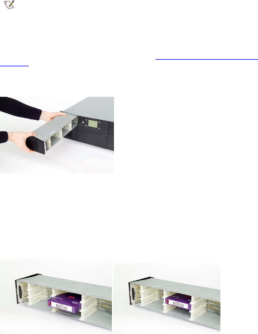
50
Running the Library
Removing the Magazine from the Unit
The following
illustration shows the correct way to remove the magazine from its bay.
Note
You cannot remove the magazine if the unit is password protected or locked by
host software through a Prevent Medium Removal SCSI command.
When ejecting the magazine it auto
matically pops out a few inches. With one hand, grip the handle on
the outer side of the magazine bezel and hold the other hand under the magazine. Pull the magazine
carefully out and keep it in level with the library. If the magazine is filled with cartri
dges
,
be aware of
the weight of the magazine. Keep one hand underneath the magazine to prevent the back of the
magazine to fall down when it leaves the magazine bay. See
Figure
18
.
Removing
the
Magazine
from
the
L
ibrary
.
Figure
18
.
Removing the Magazine from the L
ibrary
Inserting Cartridges into the Magazine
When inserting cartridges, the access door of the cartridge must face the magazine
slot opening.
Push the cartridge carefully into the magazine slot until it locks in place. The rear side of the cartridge
with the Write Protect switch and the barcode label must face out. Make sure the cartridges latch
properly.
Figure
19
.
Gently
P
ush the
C
artridge into the
M
agazine
S
lot
Removing Cartridges from the Magazine
Press the cartridge release tab towards the cartridge until the cartridge is released. The cartridge is
spring loaded, so it is important to prevent the c
artridge from popping all the way out.
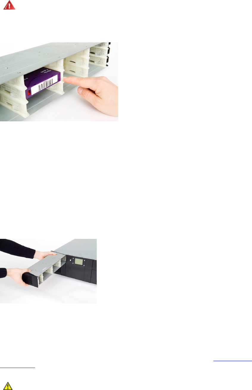
StorageLibrary Installation and User Guide
51
Warning
If the cartridge falls down, it might be damaged and data could be lost.
Figure
20
.
Push
the Release Knob t
owards
t
he Cartridge
t
o Eject
t
he Cartridge
from t
he Slot
Inserting
a Magazine into the Unit
The right and left magazines are mirrored and can only be inserted into the correct left or right
magazine bay.
1.
Enter the back of the magazine into the correct magazine bay. Make sure it is in level with the
library.
2.
Slide the ma
gazine carefully in u
ntil the eject spring engages.
3.
Push the magazine further in against the spring until the magazine is latched.
Figure
21
.
Push
Magazine
u
ntil
i
t Clicks into Place
Manual/Emergency Release of Magazines
In fail
ure situations (either in the library itself, a power loss, or situations where you need to manually
release the magazines), a manual/emergency release is available. To activate the emergency
magazine feature, you must use the magazine release tool that is
fastened to the rear of the library.
This tool must be inserted through the hole
at the bottom of each magazine. See
Figure
22
.
The
Release
Tool
.
Caution
Make sure to turn off th
e power before you use
the manual
emergency release
tool

52
Running the Library
Figure
22
.
The
Release Tool Inserted into the Correct Hole on the Left Lower Magazine
Standby Functionality
On the front panel a standby button is available.
To activate
Standby mode, press the button for a minimum of 2 seconds. The
StorageLibrary
will
enter a standby mode in a controlled manner. The following takes place before the
StorageLibrary
goes into standby mode:
1
Finish any
StorageLibrary
activity
.
2
The power to the
tape drives are switched off
.
3
The display is turned off
.
4
No
StorageLibrary
activity is allowed until the
standby button is pressed again
.
5
The green LED on the front will blink wi
th short blinks
-
long intervals
.
6
To leave the standby mode, press the standby
button for 2 second. The
StorageLibrary
will then
restart and perform a full i
nventory
.

StorageLibrary Installation and User Guide
53
8 Getting Status and Information
Operator
s and
Administrator
can view information about the library by accessing the items under the
Re
ports menu. The Reports menu information is available from both the front panel interface and t
he
remote management interface. H
owever we recommend
using
the remote management interface to
view the reports due to the limited number of information available
on the small FPI screen. Also the
FPI reports show a subset of the RMI reports only.
The status listed in this chapter is the reports available from the remote management interface. For an
overview of the reports available from the front panel interface r
efer to the
front panel menu map in
figure 14 Front Panel Interface Menu Tree
.
Viewing Library Settings
The Library Settings report contains information on the following library settings:
Inquiry string
FPI
Password
-
Enabled or Disabled
Menu Timeout
fro
m 1 to 9
Barcode Scanner
-
Enabled or Disabled
Date and Time
-
Current date and time
Audible Alarm
enabled or disabled
Library Serial Number (Library SN)
Library Firmware Version (Library FW)
The path to open the report from the
RMI
is
Reports > Librar
y.
Viewing Partitions/Drive Settings
The Library Partitions/Drive Settings report is a dynamic representation of the physical locations of
various library resources, including tape drives, slots, partitions, and modules.
The following drive information is
available from the Partitions/Drive report:
Drive Vendor Name <value>
Drive Product Name <value>

54
Getting Status and Information
SCSI ID <value as applicable>
Fibre Channel ID <value as applicable>
Fibre Topology <value as applicable>
Fibre Channel Speed <value as applicable>
Assigned P
artition <1, 2, 3, or 4>
Control Path <Enabled, Disabled>
Drive Serial Number (Drive SN): <value>
Drive Firmware Version (Drive FW): <value>
World Wide Name
World Wide Node Name
The following partition information is available from the Partitions/Drive rep
ort:
Partition Number
Control Path
<No or
Yes,
Drive ID>
S
tatus
<online/offline>
Number of s
lots
Drive ID numbers for drives in the partition
Total number of cartridges
Barcode Mode <6 Character or 13 Character>
Autoclean <Enabled or Disabled>
The path to
open the report from the
RMI
is
Reports > Partitions/Drive Settings.
Viewing Network Settings
The Network Settings report provides information on the following library settings:
Network Settings
Address mode (static or dynamic), IP address, subnet mask, ga
teway, and
MAC address
Notification
SNMP server IP address, e
-
mail address, n
otification enabled or
disabled,
notification severity
The path to open the report from the
FPI
or from the
RMI
is
Reports > Network Settings.
Viewing Statistics
The Viewing Stati
stics report captures the statistics of the library.
Gets (Fetches)
Puts (Stows)
Power on Hours
Time since drive cleaning
The path to open the report from
FPI or RMI
is
Reports > Statistics
.

StorageLibrary Installation and User Guide
55
Viewing Log
The viewing log report provides information on librar
y events and errors.
The path to open the report from the
RMI
is
Reports > Log.

StorageLibrary Installation and User Guide
57
9 Adding, Removing and Replacing
This chapter describes how to add, remove, and replace hardware within your library. Adding,
removing, or replaci
ng library components require you to power off the entire library.
Power
Supply Unit
The switch on the rear of the library shuts down power
to the library
.
Removing and Replacing a Power
Supply
These instructions explain how to remove a power
supply
and re
place it with a new one.
You must power off the library before performing this procedure.
Required tools
: None
1
Access the back of the library, and locate the power supply
that you want to replace.
2
Turn off the power
of the library
using the sw
itch on the
rear.
3
Disconnect the power cord
.
4
Loosen the power
supply
thumbscrews. Lo
osen both screws simultaneously. See
Figure
23
.
Replacing
a
Power
.
5
Remove the power supply
by gripping the thu
mbscrews and pulling it toward you.
6
Insert the new power
supply
into the vacant power
supply
bay
.
When inserting the power
supply
, make sure that you insert it correctly
.
The power
supply
must be
level
to slide in smoothly.
7
Tighten the power
supply
thumbsc
rews to secure the power supply to the library module. Tighten
the two thumbscrews simultaneously.
8
Reconnect the power cord
.
9
Turn on the power switch on the
rear
end
of the library.
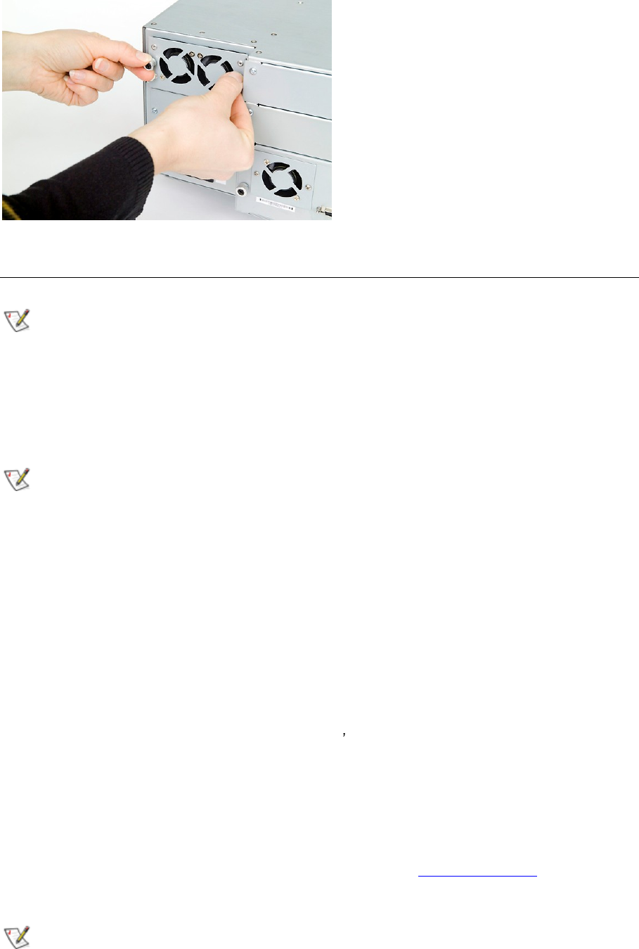
58
Adding, Removing and Replacing
Figure
23
.
Replacing a Power
Supply
Tape Drive
Unit
Note
To make sure you do not interrupting your host system we recommend that you
power off your library before you add, remove or replace a tape drive unit
Adding a
Tape Drive
You can add tape drives so that your library contains four half height d
rives, two full height drives or a
combination of these.
Note
A
full height drive
can
occupy the bottom two half height drive positions, the top
two half height drive positions, but not the middle two half height drive positions.
These instructions
explain how to add a
tape drive
to your library.
Required tools:
Screwdriver.
1
Turn off the power to the library using the switch on the rear.
2
Detach the cover plate f
or
the bay where the
tape drive
will be added. Use a screwdriver to loosen
the cover plate
screws and remove the plate
.
Save the cover plate. If you later decide to remove
the tape drive, you will need to reinstall the cover plate
.
3
Insert the
tape drive
into the drive
bay
. Using the guide rails on both the
tape drive
and in the
drive
bay
, slowl
y slide the
tape drive
into the
bay
. The
tape drive
must be
level
to slide in smoothly.
4
Tighten the thumbscrews to secure the
tape drive
to the module.
The thumbscrews must be aligned with the module s screw holes. If they are not aligned, the
tape
drive
w
ill not be inserted correctly. Tighten the thumbscrews simultaneously.
5
Connect the host interface cables to the
tape drive
.
If the
tape drive
is a SCSI drive, and the drive
is the last device on the bus, you must also connect the SCSI terminator.
6
Power on
the library
.
7
Run the setup wizard from the front panel interface or the remote management interface.
8
Update Drive firmware by following the instructions provided in
Updating
Firmware
. The libra
ry
can use the d
rive immediately after the tape drive firmware is downloaded.
Note
If you do not have
a cover plate, order a replacement. It is important that all vacant
slots have a cover plate to keep unwanted materials out of the library.

StorageLibrary Installation and User Guide
59
Permanentl
y Removing a
Tape Drive
These instructions explain how to remove a
tape drive
that you do not intend to replace with another
one.
You
CANNOT
remove a
tape drive
while the library is powered on.
Required tools:
Screwdriver
.
1
Prepare host applications for
ta
pe drive
removal.
2
Using the remote management interface
or the front panel interface
,
remove the drive from the
partition that uses the target tape drive.
3
If there is a cartridge in the target tape drive, use the remote management interface
or the front
p
anel interface
to eject it
.
4
Power off the library.
5
Disconnect the host interface cables from the
tape drive
that you want to remove.
6
From the back of the library, loosen the
tape drive
thumbscrews.
7
Remove the
tape drive
by gripping the thumbscrews and pull
ing the entire
drive unit
toward you.
8
Install a cover plat
e over the vacant
drive
bay
. Use a screwdriver to mount the plate.
If you do not have a cover plate, order a replacement. It is important that all vacant slots have a cover
plate to keep unwanted ma
terials out of the library.
Warning
Running the library without a cover plate can be dangerous.
Removing and Replacing a
Tape Drive
These instructions explain how to remove a
tape drive
and replace it with a new one.
Required tools:
None
.
1
Prepare hos
t applications for tape drive removal.
2
If there is a cartridge in the
D
rive, use the remote management interface to eject it.
3
Power off the library
.
4
Disconnect the host interface cables from the
tape drive
that you want to remove.
5
From the back of the libr
ary, loosen the
tape drive
thumbscrews.
6
Remove the tape drive by gripping the thumbscrews and pulling the entire tape drive toward you.
7
Add the new tape drive to the vacant slot. Using the guide rails on both the ta
pe drive and the
tape drive bay
, slowly s
l
ide the tape drive into the bay
. The tape drive must be level to slide in
smoothly.
8 Tighten the tape drive s thumbscrews to secure the tape drive to the module. Tighten
the
thumbscrews
simultaneously;
see
Figure
24
.
Adding,
R
emoving
or
Replacing
a
Tape
Drive
.
The thumbscrews must be aligned with the module s screw holes. If they are not aligned, the tape
drive was not inserted correctly
.
9
Connect the host interf
ace cables to the tape drive.
If the
tape drive
is a SCSI drive, and the drive
is the last device on the bus, you must also connect the SCSI terminator.
10
Power on the library.
11
If necessary, update
D
rive firmware by following the instructions provided in the
Updating
Firmware
. The library can use the tape drive immediately after the tape drive firmware is
downloaded
.
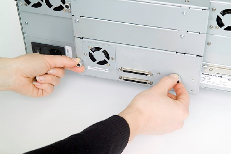
60
Adding, Removing and Replacing
Figure
24
.
Adding, R
emoving or Replacing a
Tape Drive

StorageLibrary Installation and User Guide
61
10 Updating Firmware
The Administrative User can update firmware on the
StorageLibrary
if required. The latest firmware
versions for the library can be found on
http://www.tandber
gdata.com
, Support, choose
StorageLibrary T40 under Tape Automation
and download the firmware file to your computer
.
You can also regularly monitor the website for firmware updates, but you need to make sure that the
firmware you download is compatible wi
th your library and tape drives.
There are two types of firmware that can be updated on the library: library firmware and tape drive
firmware. This chapter explains how to update both the library firmware and the tape drive firmware.
Updating Library Firmw
are
With the
Update Library Firmware
command, you can install new library firmware from the remote
management interface.
Caution
If you choose to update tape drive firmware during this
procedure, make sure that
cartridges
are not
loaded in any of the ta
pe drives. If cartridges
are
loaded
in tape
drives during the update process, the library loses knowledge of the cartridge
home cell in storage, resulting in library and host inventory issues.
Update the library application firmware using the following s
teps:
1
Download Library Firmware
.
Access
http://www.tandbergdata.com
,
Support, choose StorageLibrary T40 under Tape
Automation
and download the firmware file to your
computer
.
a.
From the home page, navigate to your
product s firmware.
b.
Verify with technical support or published
Release Notes
that you are selecting the corre
ct
firmware version to download
.
a.
Select the appropriate firmware version and download the files to your computer hard
drive.
2
Update Library Firmwa
re
.
Update the library application firmware using the
Library FW Upgrade
command on the
Tools
>
Maintenance
menu from
the remote management interface.
a.
Browse to the firmware file that was downloaded in
Step 1 and apply the selection
.

62
Updating Firmware
b.
Click on the Upgrade
button. The upgrade process has
now started
.
Caution
After the update process starts, you must wait until it completes. Do not attempt
to interrupt the process in any way. Loss of data or library operability could occur.
After uploading the file, the
remote management interface is
inoperable
. The progress of the FW
upgrade process is displayed on the front panel interface.
When the FW upgrade has completed, the library reboots.
The
library is now accessible on the
RMI.
a.
Open the
Reports > L
ibrary Sett
ings
report to verify that the
library firmware was
updated
.
Updating Drive Firmware
You can update tape drive firmware using the TDKit software. The TDKit software can be downloade
d
from the
Tandberg
web site
ww
w.tandbergdata.com
. The program is available for Windows XP,
Windows 2000/2003, and Windows NT.
You usually want to update firmware on all of the tape drives in the library at the same time to make
sure that all of the tape drives are at the same firmware
level. You do not want to use different levels
of tape drive firmware in the library.
It is important to make sure that the library is running the appropriate level of tape drive firmware,
compatible with the tape drive type. To determine the appropriate
tape drive firmware, refer to the
library s
Release Notes
or contact Technical Support.
After you have identified the need to update tape drive firmware on one or more tape drives, use the
following steps to load the firmware onto the tape drives.
1
Download
and install the TDKit software in
your computer
.
When started
,
the TDkit displays all detected SCSI devices.
Make sure the computer has detected the tape drive. (Look for Tape drives in the Device
Manager :
Right click "My Computer"
Manage
Device Manager ).
Most Windows operating systems require that all backup services started by the backup software
application
must
be stopped before the TDKit util
ity is started.
Make sure that no windows driver is loaded for the tape drive in question, as this
will block the
SCSI port for the flashing utility and TDKit will not see the drive (select and disable the tape drive
in the Device Manager:
My Computer
>
Manage
>
Device Manager
).
2
Download drive Firmware
.
Access the drive manufacturer s web site and down
load the firmware file to your computer.
a.
From the home page, navigate to your product s firmware.
b.
Verify from the published Release Notes or
Tandberg
Technical Support that you are
selecting the correct firmware version to download
.
a.
Select the appropriate
firmware version and download the files to your computer s
hard drive. Download the fi
rmware anywhere in the computer
.
3
Update Library Firmware
.
a.
Start the TDKit utility and follow
the instructions in the program
.
4
Verify Drive Firmware Update
.
Open the
Driv
e Info
report to verify that the tape drive firmware was updated.
The paths to open the appropriate screen are:
From the
RMI
, select
Tools > Drive Settings

StorageLibrary Installation and User Guide
63
From the
FPI
, select
Tools
>
D
rive Setting
s

StorageLibrary Installation and User Guide
65
11 Working With Cartridges and Barcodes
This chapter describes how to work with cartridges and barcodes. When working with cartridges,
there are certain considerations that should be taken into account. For example, all cartridges in the
library must have a barcode label. In additi
on, when loading your library, you should be aware of
whether or not your cartridges are write
-
protected.
This section discusses these types of items in general terms. For information on what type of tape
cartridges are supported for listed tape drive type
s, refer to Specifications
.
Every partition in the library must contain at least one cleaning cartridge.
Handling Cartridges Properly
To ensure the longest possible life for your cartridges, follow
these guidelines:
Select a visible location to post procedures that
describe proper media handling
.
Ensure that anyone who handles cartridges has been pro
perly trained on all procedures
.
Do not drop or strike cartridges. Excessive shock could damage the in
ternal contents of cartridges
or the casings themselves, re
ndering the cartridges unusable
.
Do not expose cartridges to direct sunlight or sources of heat, including por
table heaters and
heating ducts
.
Do not stack
cartridges more than five high
.
The opera
ting temperature range for LTO cartridges is 10º
35ºC. The storage temperature range
is 16º
32ºC in a dust
-
free environment with a relative humidity range b
etween 20%
80% (non
-
condensing)
.
If cartridges have been exposed to temperatures outside the ranges
specified above, stabilize the
cartridges at room temperature for the same amount of time they were exposed to extreme
temperatures
or 24 hours, whichever is less
.
Do not place cartridges near sources of electromagnetic energy or strong magnetic fields, su
ch as
computer monitors, electric motors, speakers, or x
-
ray equipment. Exposure to electromagnetic
energy or magnetic fields can destroy data and the embedded servo code written on the media by
the cartridge manufacturer, re
ndering the cartridges unusable
.
Place identification labels only in the des
ignated slots on the cartridges
.
If you ship cartridges, ship them in their original
packaging or something stronger
.
Do not insert dama
ged cartridges into tape drives
.

66
Working With Cartridges
and Barcodes
Do no
t touch the tape or tape leader
.
C
aution
Do not degauss cartridges that you intend to reuse.
Write
-
Protecting Cartridges
All cartridges have a write
-
protect (write
-
inhibit) switch to prevent accidental erasure or overwriting of
data.
Before loading a cartridge into the library, make sure
that the write
-
protect switch is positioned
correctly (either on or off).
The switch is located on the left side of the cartridge front. Slide the red or orange write
-
protect switch
to the right so that the padlock shows in the closed position.
Barcode Req
uirements
Cartridges must have an external barcode label that is machine and operator
-
readable. A barcode
must use only uppercase letters A to Z and/or numeric values 0
9. The library supports Code 39 (3 of
9) type barcodes.
For LTO media barcodes, the lib
rary supports six characters for the barcode plus a two
-
character
media type identifier.
Caution
You must use
StorageLibrary
specific barcode labels supported by
Tandberg
to
ensure reliable functionality of the barcode reader.
Installing Barcode Labels
Each cartridge in the library must have an external label that is operator and machine readable to
identify the barcode.
All barcode labels must be applied to the front of a cartridge. Peel off the label and place it on the
cartridge.
Verify that the labe
l is
positioned as illustr
ated in figure 13
. The cartridge cannot have any stickers or
labels attached to the top or bottom because if the labels come loose, they can get caught in the tape
drives or become unreadable by the scanner.
Caution
Do not plac
e a barcode label on top or bottom of a cartridge. Doing so can cause
inventory operations to fail.

StorageL
ibrary Installation and User Guide
67
12 Troubleshooting
The library includes advanced system monitoring and alerting mechanisms that inform you of library
status
and issues. It also notifies you of issues it detects and guides you through diagnosing and
correcting issues before problems interfere with backups.
This chapter describes commands that you can select from the
Tools
menu to monitor the library,
configure
and test tape drives, work with connectivity, e
-
mail current logs, and save and restore library
configurations.
About
RAS Tickets
The library uses advanced problem detection, reporting, and notification technology to alert customers
of problems as soon as
they occur. The library performs numerous self
-tests to monitor the library s
temperature, voltage and currents, and standard library operations. It performs these self
-
tests each
time the library is powered on, and during normal operation when the librar
y is idle.
If the self
-
test detects a problem, the library generates a service report, or RAS
ticket, which
identifies
which
component,
is likely causing the problem. The library s LEDs may also turn on or off and flash
to indicate an abnormal state. If th
e problem is not severe, the library continues to provide full
functionality to all unaffected partitions.
When possible, the library provides instructions for resolving problems. These instructions appear on
the library s front panel, and are also availab
le via the remote management interface. Access the
library s online Help system if you have questions about the instructions provided.
Viewing
RAS Tickets
From the
Tools
menu on both the front panel and the remote management interface, you can view
library
RAS tickets. RAS tickets are special service reports that summarize the current reliability,
availability, and serviceability of the library. RAS tickets provide detailed information about system
problems. From the remote management interface and the fron
t panel interface, this view lists all of
the library RAS tickets in the order in which they were created starting with the most recent. All RAS
tickets are considered unopened until a
user
clicks
OK
. After you click
OK
, the ticket is considered
opened.
Al
so included on the RAS tickets log is an explanation of what error the library encountered.
The paths to open the appropriate screen
s
are:
From the
RMI
, select
Tools > Diagnostics > Capture Logs
From the
FPI
, select
Tools > Diagnostics > Capture Logs

68
Troubleshooting
Closi
ng RAS Tickets
After using the information in the RAS ticket to resolve your library issue, use the prompts on the
screen to close the RAS ticket.
Supported RAS Tickets
Table
6.
Supported RAS Tickets
Parameters and Priority
RAS
Tic
ket
Display Message
Description
Suggested Action
01ZZ
Diagnostic number
ZZ failed.
The diagnostics number
ZZ failed.
Reboot the loader and retry the operation.
0200
Initialization of the
robotics failed.
The robotics failed to
complete the calibration
or
the inventory
sequence.
Reboot the loader and retry the operation.
Verify that the magazines are locked.
Turn off the loader and try to remove the
magazines by using the emergency eject
pin.
Contact your service representative.
1001
Failed moving the
ro
botics.
The robotics was not
able to move.
Reboot the loader and retry the operation.
1101
-
1128
Failed to stow at
slot n
The robotics is not able
to stow the cartridge to
the magazine
Reboot the loader and retry the operation.
Remove the magazine if possi
ble. Remove
all cartridges.
Verify that the cartridge is not damaged.
Insert empty magazines.
Power cycle the loader.
Retry the operation.
Retry the operation with a new magazine.
1129
-
112C
Failed to stow at
drive n
Failed to insert cartridge
in drive
Re
boot the loader and retry the operation.
If failure persists, insert the cartridge into a
magazine slot, remove the magazine and
verify that the cartridge is not damaged.
If failure persists, replace the drive CRU.
1201
1228
Failed to fetch at
slot n
Th
e robotics is not able
to fetch the requested
cartridge from the
magazine
Reboot the loader and retry the operation.
Remove the magazine if possible. Remove
all cartridges.
Verify that the cartridge is not damaged.
Insert empty magazines.
Power cycle the l
oader.
Retry the operation.
Retry the operation with a new magazine
1229
-
122C
Failed to fetch at
drive n
Failed to fetch cartridge
in drive
Reboot the loader and retry the operation.
If failure persists, replace the drive CRU.
6003
Drive n Tape Alert
3.
Hard Error
The operation has
stopped because an
error has occurred while
reading or writing data
which the drive cannot
correct.
Clean the drive.
Try another cartridge.
If failure persists, replace the tape drive.

StorageL
ibrary Installation and User Guide
69
RAS
Tic
ket
Display Message
Description
Suggested Action
6004
Drive n Tape Alert
4. Media
The ope
ration has
stopped because an
error has occurred while
reading or writing data.
Your data is at risk:
Copy any data you require from this tape.
Do not use this tape again.
Restart the operation with a different tape.
6005
Drive n Tape Alert
5. Read Failur
e
The tape is damaged or
the drive is faulty.
Clean the drive.
Try another cartridge.
If the problem persists, replace the tape
drive.
6006
Drive n Tape Alert
6. Write Failure
The tape is from a faulty
batch or the tape drive
is faulty.
Clean the drive.
U
se a good tape to test the drive.
If the problem persists, replace the tape
drive.
6007
Drive n Tape Alert
7. Media Life
The tape cartridge has
reached the end of its
calculated useful
Life.
Copy any data you need to another tape
Discard the old tape.
6008
Drive n Tape Alert
8. Not Data Grade
The tape cartridge is not
data-
grade. Any data
you back up to
the tape is at risk.
Replace the cartridge with a data
-
grade tape.
6009
Drive n Tape Alert
9. Write Protect
You are trying to write to
a write
-
protected
cartridge.
Remove the write
-
protection or use another
tape.
6012
Drive n Tape Alert
12.Unsupported
Format
You have tried to load a
cartridge of a type which
is not supported by this
drive.
Use another tape.
6020
Drive n Tape Alert
20. Clean Now
The tape
drive needs
cleaning.
If the operation has stopped, eject the tape
and clean the drive
If the operation has not stopped, wait for it
to finish and then
Clean
the drive.
Check the user manual for cleaning
instructions.
6022
Drive n Tape Alert
22. Expired
C
leaning Media
The last cleaning
cartridge used in the
tape drive has worn out.
Discard the worn out cleaning cartridge.
Wait for the current operation to finish.
Then use a new cleaning cartridge.
6030
Drive n Tape Alert
30. Hardware A
The tape drive has
a
hardware fault.
Eject the tape.
Reset the drive.
Restart the operation.
6031
Drive n Tape Alert
31. Hardware B
The tape drive has a
hardware fault.
Turn the tape drive off and then on again.
Restart the operation.
If the problem persists, call the tape
drive
supplier helpline.
6032
Drive n Tape Alert
32. Interface
The tape drive has a
problem with the host
Check the cables and cable connections.
Restart the operation.

70
Troubleshooting
RAS
Tic
ket
Display Message
Description
Suggested Action
interface.
6034
Drive n Tape Alert
34. Download Fail
The firmware download
has failed
because you
have tried to use the
incorrect firmware for
this tape drive.
Obtain the correct firmware and try again.
6036
Drive n Tape Alert
36. Drive
Temperature
Environmental
conditions inside the
tape drive are outside
the specified
temperature range
Verify that the drive CRU fan is running.
6039
Drive n Tape Alert
39. Diagnostics
Required
The tape drive may
have a fault.
Check for availability of diagnostic
information and run extended diagnostics if
applicable.
Check the tape drive users manual for
instructions on running extended
diagnostic tests and retrieving diagnostic
data
01ZZ
Diagnostic number
ZZ failed.
The diagnostics number
ZZ failed.
Reboot the loader and retry the operation.
0200
Initialization of the
robotics failed.
The robotics fail
ed to
complete the calibration
or the inventory
sequence.
Reboot the loader and retry the operation.
Verify that the magazines are locked.
Turn off the loader and try to remove the
magazines by using the emergency eject
pin.
Contact your service represent
ative.
1001
Failed moving the
robotics.
The robotics was not
able to move.
Reboot the loader and retry the operation.
1101
-
1128
Failed to stow at
slot n
The robotics is not able
to stow the cartridge to
the magazine
Reboot the loader and retry the operat
ion.
Remove the magazine if possible. Remove
all cartridges.
Verify that the cartridge is not damaged.
Insert empty magazines.
Power cycle the loader.
Retry the operation.
Retry the operation with a new magazine.
1129
-
112C
Failed to stow at
drive n
Faile
d to insert cartridge
in drive
Reboot the loader and retry the operation.
If failure persists, insert the cartridge into a
magazine slot, remove the magazine and
verify that the cartridge is not damaged.
If failure persists, replace the drive CRU.
Interpr
eting LEDs
LEDs provide a visual indication about the status of certain library components. LEDs can sometimes
communicate that a problem exists when the RAS ticket cannot. For example, an LED can indicate a
firmware problem that prohibits the library from
generating RAS tickets.

StorageL
ibrary Installation and User Guide
71
The following components of the library have LEDs
:
Library
Ethernet status LED
The Maintenance Menus
Table
7.
Maintenance Menus
-
Item Name and Description
Item name
Description
Library FW upgrade
Upgrades
the library FW through RMI
Prepare to Ship
When selected, the robotics is positioned fo
r installing the
transport locking
screws.
The magazines are ejected to facilitate the installation.
The library cannot be safely shipped with cartridges in the magazin
es.
Th
e Prepare to ship command must be run before the library is transported to
reinstall the transport l
ocking screws
and to remove all cartridges in the
library.
Reboot
Performs a hard reset of the library.
Restore default
Sets the library settings to
their factory default values.
Clear WEB password
Clears the WEB password (from FPI only)
The Diagnostics Menu
Table
8.
Diagnostics Menu
-
Item Name and Description
Item name
Description
Capture logs
Displays a log that contains i
nformation about library and drive configuration,
event log and error log. This log can be saved to a file or sent via e
-
mail to
technical support.
System test
Runs a test of the library hardware.
Cycle test
Starts a test where cartridges are moved rando
mly between magazine slots
and between the drive and the magazines.
Verifying Hardware
1.
The library uses one SCSI ID for each SCSI tape drive. Verify that the drive SCSI IDs are set to
unique SCSI IDs that are not used by any other SCSI device on the same
bus. Depending on
other devices attached to the same SCSI bus and their SCSI IDs, you may need to change the
SCSI ID of the tape drive(s) before you can use the library.
2.
Verify that the system recognizes the tape drives during the boot process.
3.
Verify that
the SCSI host adapter recognizes the tape drives during its initialization.
4.
Verify that the status on the library s front panel interface is OK.
5.
Verify that the power cable is inserted correctly.
6.
Verify that the SCSI cables are properly connected at both
ends. Check that the cables are not
damaged, and verify the lengths of your SCSI cabling. The length of the internal SCSI cabling
inside the library is 30cm. This length must be included in any calculation of cable length.
7.
Verify that the SCSI bus is prope
rly terminated. Only the devices physically at the beginning and
end of the cable must be terminated.

72
Troubleshooting
Software
C
hecking
1.
Verify that the SCSI
-
controller can see all devices during boot sequence. If not, enter HBA
-
bios
and check that LUN
-
scanning is enable
d.
2.
Verify that operating system can see all SCSI devices, both robotics and tape
-
drives
.
3.
Verify that drivers are loaded properly. Some applications use their own drivers so the device
should appear "unknown" in device manager. Normally drivers from hardw
are vendor should be
preferred.2
.
4.
Verify that the Backup software detects loader and drives properly and does not report errors.
Run "Device Configuration Wizard" again if needed.
Verifying Recent Changes
If the library has been installed previously and o
perated correctly but is now incurring a problem, verify
any recent changes to the system to ensure that these changes are not causing the problem. Try the
following:
1
If the system configuration has changed: Remove the change to see if it affected the libr
ary.
2
If an operating system corrective patch has been installed: Remove it to see if it affected the
library.
3
If a SCSI device has been added: Check for SCSI ID conflicts.
4
If a SCSI device has been added: Check if the SCSI termination has been properly set
.
Troubleshooting
M
atrix
The table below describes different problem situations and suggested actions to try to resolve the
problem.

StorageL
ibrary Installation and User Guide
73
Table
9.
Troubleshooting
Matrix
Power
with Solution
Problem
Solution
Power
Library does not po
wer on
Check the power cord connection.
Make sure the power switch on the rear panel is in the ON
position.
Make sure there is power to the outlet. Try another working
outlet.
Replace the power cord.
Make sure that the fuse located beside the power connect
or
on the rear panel is not blown. Replace fuse if blown (a spare
fuse is located behind the fuse door).
Verify that the power
supply unit
is properly inserted into the
bay.
Replace the power supply
unit
.
Contact your service representative.
The display i
s dead
Power cycle the library by turning off and on the main power
switch on the rear of the library.
Verify that the
fans start
at power on and then stops after a
few seconds.
Check the power cord connection.
Make sure the power switch on the rear panel
is in the ON
position.
Make sure there is power to the outlet. Try another working
outlet.
Replace the power cord.
Make sure that the fuse located beside the power connector
on the rear panel is not blown. Replace fuse if blown (a spare
fuse is located beh
ind the fuse door).
Verify that the power
supply unit
is properly inserted into the
bay.
Replace the power supply
unit
.
Contact your service representative.
The front panel does not
display information but the back
light on the front panel is on
Power cyc
le the library by turning off and on the main power
switch on the rear of the library.
Verify that the fans start at power on and then stop after a few
seconds.
Contact your service representative.

74
Troubleshooting
Table
10
.
Troubleshooting
Matrix
Cartridge Movement with Solution
Problem
Solution
Cartridge M
ovement
Library does not take
inventory
Make sure the transport screws are removed.
Make sure all magazines are in their locked position.
Write down any error information given on the FPI or
RMI
.
Contact your service representative.
Cartridge
stuck
in drive
Power cycle the library by turning off and on the main power
switch on the rear of the library. Allow both the library and the
drive to complete initialization, which in rare cases can ta
ke as
long as 10 minutes, and then retry unloading the tape from the
FPI or RMI.
Make sure that the backup software is not reserving the slot or
preventing the tape drive from ejecting the cartridge. The
backup software needs to cancel the reservation and
any hold it
has on the tape drive.
Temporarily disconnecting the library from the host server
system eliminates the host system and its software as a
problem source.
Remove
the tape drive unit
from the drive bay. Connect power
to the drive either by connec
ting it to the library s power supply
or to an external power supply. Try to eject the cartridge by
pushing the drive s eject button.
The drive
unit
can be
connected to the library s power supply by using the power
extension cable located behind the batter
y holder cover plate
on the rear of the library.
Follow the drive s emergency eject procedure to remove the
cartridge from the drive.
Replace the
tape drive unit
.
Contact your service representative.
Cartridge
stuck
in magazine
Eject the magazine using th
e front panel interface. Manually
remove the cartridge from the magazine slot.
Contact your service representative.
Cartridge
stuck
in robotics
Power cycle the library by turning off and on the main power
switch on the rear of the library.
Write down any
error information given on the FPI or RMI
.
Contact your service representative.
Failed to move cartridges
Write down any error information given on the FPI or RMI
.
Contact your service representative.
Failed to insert cartridge into
drive
Check failing m
edia for pin damage (buckling pin).
Hold the cartridge in your hand with the Write Protect Switch to your
left and orientation arrow pointing
away
from you. On the right side
all the way in front is a small door that can be opened by sliding a
door against
you. Inside the cartr
idge you should see a metal pin.
T
he pin shall be parallel with the cartridge front and is hold in place
by to metal grippers at each end (top and bottom of the cartridge).
The media should be attached to this pin, and you see only th
e top
and bottom part of the pin. If the pin is missing, loose or damaged
the tape will be damaged and rejected from the drive.

StorageL
ibrary Installation and User Guide
75
Table
11
.
Troubleshooting
Matrix
Media with Solution
Problem
Solution
Media
Media barcode labels
Make sure the barcode labels are applied in the correct
orientation on the cartridge. See
Labeling
Cartridges
for
the
Barcode
Reader
.
Make sure there
are
no wrinkles on the l
abel.
Make sure that
StorageLibrary
specific labels are used.
If all of the above are OK, replace the label with a new one.
If problem continues, contact your service representative.
Data cartridge incompatible with
drive
Make sure you are using a data cartridge that is compatible
with the drive. See the tape drive s reference manuals for
details.
The SW backup application detects if an incompatible data
cartridge is used, and communicates this to the
user
.
Remove the cartridge from the library.
Cannot wr
ite to or read from
tape
Make sure that the cartridge is write enabled (move the write
-
protect switch to the enabled position).
Make sure that the cartridge has not been written using an
incompatible format.
Make sure that the cartridge is an acceptable f
ormat for your
drive type.
See the tape drive s reference manuals for details.
Make sure that the cartridge has not been exposed to harsh
environmental or electrical conditions and is not physically
damaged in any way.
Many backup applications do not read
or write to cartridges
that were created using a different backup application. In this
case, you may have to perform an erase, format, or label
operation on the cartridge.
Make sure you understand any data protection or overwrite
protection schemes that yo
ur backup application may be
using, which could prevent you from writing to a given
cartridge.
Retry the operation with a different, known good tape.
Clean the tape drive. See
Cleaning
Tape
Drives
.
Table
12
.
Troubleshooting
Matrix
SCSI with Solution
Problem
Solution
SCSI problems
Changed SCSI ID, but the host
server system does not
recognize the new ID
Make sure that all SCSI devices on the same bus have unique
ID nu
mbers.
If the SCSI bus is narrow (50
-
pin) only SCSI IDs 0 through 7
are available.
Make sure that you reboot the library after changing the SCSI
ID.
Reboot the host server system.
The tape drive does not
respond on the SCSI bus to the
host
Verify that a S
CSI terminator is attached to both the last and
first SCSI device on the SCSI bus.
Verify that the SCSI cables are connected to the rear of the
library. See
Connecting
Library
Cables
(SCSI).
76
Troubleshooting
Problem
Solution
SCSI problems
Make sure that the correct host controller card is installed.
Verify that the SCSI cables are not damaged and that the total
SCSI cable length is not exceeding the maximum required
length.
Verify that the drive SCSI ID
s
are set to unique SCSI ID
s that
are
not used by any other SCSI device on the same bus.
Verify that the host application and the device drivers are
installed with the most resent patches to support the tape
drive
.
Issue a system reset from the front panel or remote
management
.
Make
sure
the
tape drive
is properly inserted into the bay.
Reboot the library by turning power off from the rear of the
library and then on.
Reboot the host system when the library has co
mpleted its
power on sequence.
Contact your service representative.
Tab
le
13
.
Troubleshooting
Matrix
Library Performance with Solution
Problem
Solution
Library Performance
The library is not efficiently
backing up data
Check the network bandwidth from the host system. If you are
backing up data over
a network, consider comparing to a
local
-
only backup.
Verify that the host application and the device drivers are
installed with the most resent patches to support the tape
drive and the library.
Connect the library to an LVD SCSI bus and make sure there
are no SE devices on the same bus, because this causes the
entire bus to negotiate down to SE speed.
Clean the tape drive. See
Cleaning
Tape
Drives
.
Try a new cartridge. A marginal cartridge c
an cause
performance problems due to bad spots on the tape requiring
retries.
Backing up compressed data lowers performance.
Check the size of the files. Small file size can impact
performance.
Table
14
.
Troubleshooting
Matrix
Cle
aning with Solution
Problem
Solution
Cleaning
Cannot load the cleaning
Cartridge
Make sure there is no cartridge present in the drive before you
load a cleaning cartridge.
Make
sure the cleaning cartridge is not expired.
Contact your service representati
ve.

StorageL
ibrary Installation and User Guide
77
Table
15
.
Troubleshooting
Matrix
Write or Read Issues with Solution
Problem
Solution
Write or R
ead
I
ssues
Contaminated head
Avoid contamination by ensuring that the library is installed in a
clean, contamination
-
free envir
onment. Cartridges should be
stored vertically in their plastic cases. Continue cleaning the tape
drive as needed.
If a cleaning cartridge is not successful in resolving the problem
after 3 or more attempts, the cleaning cartridge may be
contaminated and s
hould not be used in another drive.
Non
-
acclimated media
A cartridge should be acclimated for at least 24 hours before
being used, particularly if it has been stored at a substantially
different temperature or level of humidity than the library.
Cleaning
cartridge is
Incompatible
Make sure you are using an allowed cleaning cartridge
.
Expired cleaning cartridge
Verify the number of cleanings per cleaning tape for your media
type
.
Bad/defective/contaminated
media
If the write/read errors persist and the d
rive has been
cleaned, that cartridge should be suspected as being
defective, if it is no
t an invalid cleaning cartridge.
If this occurs, export the cartridge and load a known good
cartridge. In some cases, a cartridge can be worn out, have a
defective car
tridge memory, or have been forma
tted as a
Firmware Upgrade Tape.
Any cartridge that is suspected of being defective or
contaminated should NOT be reused in any drive.
Table
16
.
Troubleshooting
Matrix LED Error Messages with Solutio
n
Problem
Solution
LED E
rror
M
essages
Amber LED on
When the amber LED is on, the library has encountered an
electrical or mechanical failure. An error message shall be
displayed
on the front panel (and RMI). Refer to
Supported
RAS
Tickets
for details.
Table
17
.
Troubleshooting
Matrix
Errors Displayed on Front Panel with Solution
Problem
Solution
Errors Displayed on Front Panel
There is an error
information
on
the
LC
D display
Write down the error information given on the FPI.
Power cycle the library by turning off and on the main power
switch on the rear of the library.
Contact your service representative.
There is an error
information
on
the RMI
Write down the error
information given on the RMI
.
Power cycle the library by turning off and on the main power
switch on the rear of the library.
Contact your service representative.
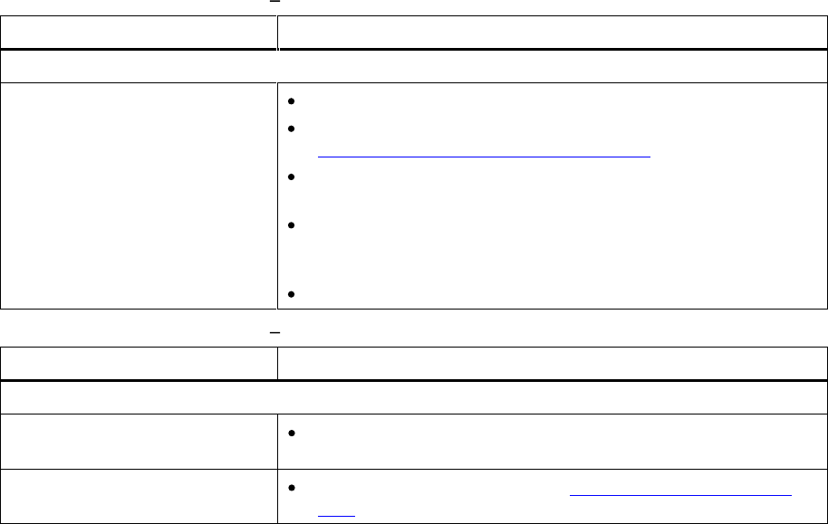
78
Troubleshooting
Table
18
.
Troubleshooting
Matrix
Remote Management with Solution
Problem
Solution
Remote Management
The unit does not respond on
the RMI
Verify that the Ethernet cable is connected to the correct hub
.
Verify the Ethernet settings via the front panel. See
Information
about
the
Operator
Interfaces
for details.
Reboot the library by issuing a system reset. Wait at least 30
seconds for the RMI to initialize.
Power cycle the library by turning off and on the main power
switch on
the rear of the library. Wait at least 30 seconds for
the RMI to initialize.
Contact your service representative.
Table
19
.
Troubleshooting
Matrix
Forgot Password with Solution
Problem
Solution
Forgot P
assword
Forgot password o
n RMI
The RMI password can be cleared from the front panel
interface.
Forgot password on FPI
Contact technical support. See
Getting
More
Information
or
Help
.

StorageLibrary Installation and User Guide
79
13 Shipping or Transporting StorageLibrary
Reinserting the Transport Lock
ing S
crews
If you need to move or ship the
StorageLibrary
you need to reinstall the transport locking screws to
protect the robotics. The screws fasten the robotics to the
chassis and hold the robotics in a locked
position. Use the instructions below to reinsert the transport
locking
screws.
1.
Locate the
transport
locking screws. They are stored in the rear of the unit and they are marked
with red plastic tabs (four M3x6 mm s
crews).
2.
From the
FPI
select
Menu > Tools > Prepare to ship
and follow the instructions displayed on the
FPI screen. The robotics will automatically be moved to the lower front position, and the
magazines will pop out.
3.
Remove the magazines
.
4.
Remove all cartr
idges from all the magazines
.
5.
Turn off the power switch on the rear of the unit
.
6.
Install the four
transport locking screws. The screws fasten the robotics to the front chassis. The
transport
locking screws are screwed into the robotics from the front of th
e library, two on each
side of the front bezel. See
Figure
25
.
Transport
Lock
ing
Screws
Marked
with
Red
Plastic
Tab
.
7.
If installed, remove the
ra
ck mount
ears.
If your library is a 24 slot version you need to remove the
two upper magazines by using the emergency eject tool. See
Manual/Emergency
Release
of
Magazines
8.
Reinsert all magazines
.
9.
If you need to ship the u
nit, use the original packaging.
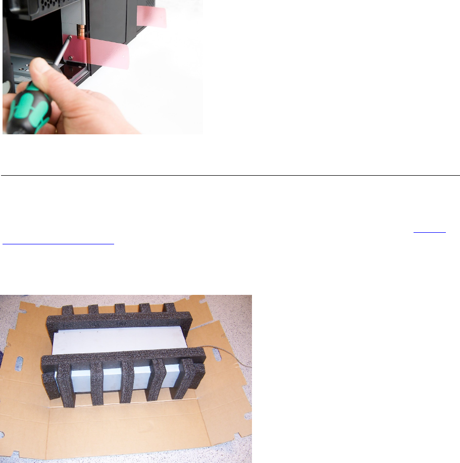
80
Shipping or Transporting
StorageLibrary
Figure
25
.
Transport
Lock
ing Screws
Marked with Red Plastic Tab
Packing the
StorageLibrary
If you want to ship the unit you need to use the origin
al packaging in order to keep the warranty. The
packaging has been designed specifically for the
StorageLibrary
for safe transportation.
If you need to order new packaging contact Technical Support. For contact information, see
Getting
More
Information
or
Help
.
Figure
26
.
Library Partly Packed
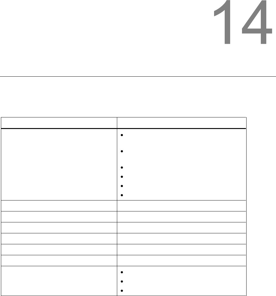
StorageLibrary Installation and User Guide
81
14 Specifications
Tandberg StorageLibrary T40s
follow the specifications described i
n this chapter. The table below lists
the library components available.
Table
20
.
Library Specification Summary
T40
Library (4U control module)
Supported Cartridges
LTO
-
1 (read
-
only in LTO
-
3 drives
, not
supported by LTO
-
4 drives
)
L
TO
-
2 (read/write in LTO
-
3 drives
, read
-
only in LTO
-
4 drives
)
LTO
-3
LTO
-
3 WORM
LTO
-4
LTO
-
4 WORM
Maximum Storage Slots Available
40
Supported Drive Types
(see chapter
16
Approved Drive Type
s)
Maximum Drive Capacity
4
Library Robot Control
LUN
Connectivity
Native drive interface
Power
120W
Library Management
Remote management
interface
Front panel interface
SNMP protocol
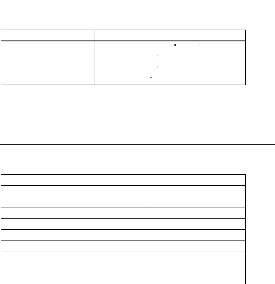
82
Specifications
Library Dimensions
The table below lists the physical dimensio
ns of the library in inches (in).
Table
21
.
Library Dimensions
Dimensions
Width
445.0 mm +/
- 0.5 mm (17.52 +/- 0.02 )
Height
176.4 mm max (6.945 )
Rear depth
770.6 mm max (30.34 )
Front depth
31.0 mm max (1.22 )
The rear depth
is measured from the rear surface of
rack mount
bracket to the rearmost feature of the
library.
The front depth is measured from the rear surface of the
rack mount
bracket to the front most feature
of the library.
Library Component Weights
The table below
lists the weights of the library hardware components
.
Table
22
.
Library Component Weight
Components
Weight
Drive CRU
FH
3600g
/
7.93 lbs
Drive CRU HH
1960
g
/ 4.32
lbs
Power CRU
875g
/ 1.93 lbs
Magazine without cartridges 8 slots
1600g
/ 3.53 lbs
Magazine without cartridges 12 slots
1890g
/ 4.17 lbs
Library with 1 FH drive
CRU
35kg
/ 77.2 lbs
Library with 2 FH drive
CRUs
38kg
/ 83.77 lbs
Library without drive
CRUs
, magazines
24.5kg
/ 54 lbs
Library without drive
CRUs
, magazin
es, power CRU
23.
55kg
/ 51.9 lbs
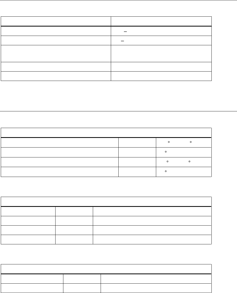
StorageLibrary Installation and User Guide
83
Power Requirements
Table
23
.
Power Requirements
Power Requirements
Values
Input Voltage
100
240 VAC
Input Frequency
50
-
60 Hz
Inrush Current (Cold Start)
Less than 15 A, 115 VAC
Less than 30
A, 230 VAC
Power Consumption Average
70 W
Power Consumption Peak*
120 W*
* Maximum peak length, less than 10ms.
Climatic Specifications
Table
24
.
Temperature Range
Temperature
Operating
Range
+10
C to +35
C
Gradient
10
C/hour
Non
-
Operating
Range -
30
C to +60
C
Gradient
20
C/hour
Table
25
.
Humidity Range
Humidity
Operating
Range
20%Rh to 80%Rh
Gradient
10%Rh/hour
Non
-
Operating
Range
10%Rh to 90%Rh
Gradient
20%Rh /hour
Table
26
.
Altitude Range
Altitude
Operating
Range -
500 to 10000 ft
Non
-
Operating
Range -
500 to 40000 ft

StorageLibrary Installation and User Guide
85
15 Safety and Regulatory Information
Safety Approvals
This product complies with the following safety standards:
Europe
EN60950
-
1:2001
USA
UL60950
-
1:2003, First Edition
Canada
CSA C22.2 No. 60950
-1-
3 1st Edition April 1
, 2003
CB report
IEC 60950
-
1:2001
EMC Approvals
This product complies with the following EMC standards:
Europe
EN55022: 1998 +A1: 2000 +A2:2003, Class A
Wa
rning: This is a class A product. In a domestic environment this product may cause radio
interference in which case the
Operator
may be required to take adequate measures.
EN61000
-3-
2: 2000
EN61000
-3-
3: 1995 +A1:2001
EN55024:1998 +A1: 2001 +A2:2003
EN61000
-6-
2: 2001
USA
FCC part 15, Class A
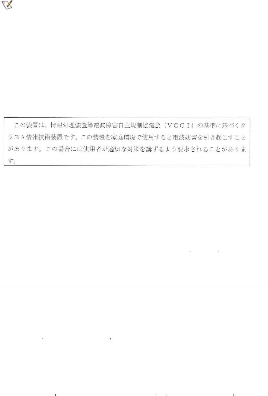
86
Safety and Regulatory Information
Note
This equipment has been tested and found to comply with the limits for a Class A
digital device, pursuant to Part 15 of the FCC Rules. These limits are designed to
provide reasonable protection against harmful int
erference when the equipment is
operated in a commercial environment. This equipment generates, uses, and can
radiate radio frequency energy and, if not installed and used in accordance with
the instruction manual, may cause harmful interference to radio c
ommunications.
Operation of this equipment in a residential area is likely to cause harmful interference in which case
the
Operator
will be required to correct the interference at his own expense.
Japan
VCCI, Class A
Translation:
This is a Class A product based on the standard of the Voluntary Control Council for Interference by
Information Technology Equipment (VCCI). If this equipment is used in a domestic environment, radio
interference may occur, in which case, the
Operator
may be required to take corrective actions.
Canada
ICES
-
003
This Class A digital apparatus complies with the Canadian ICES
-
03.
Cet appareil numérique de la classe A (ou classe B, si ainsi indiqué sur l étiquette d enregistration) est
conforme á la norme NMB
-
003 du Canada.
Confo
rmity
D
eclarations
Europe
CE
Marking by the CE symbol indicates compliance of this system to the applicable Country Directives of
the European Unio
n, including the EMC directive
(89/336/EEC) and the Low Voltage Directive
(73/23/EEC). A Declaration of Conformity in accordance with the applicable directives has been
issued for this product.
Australia/New Zealand
C-
Tick, Class A
Marking by the C
-
Tick symbol indicates compliance of this system to the Australian EMC standard
AS/NZS 3548: 1995: Information Technological Equipment . A Declaration of Conformity in
accordance with the applicable standard has been issued for this product.

StorageLibrary Installation and User Guide
87
16 Approved Drive Types
T
he following drive types are approved for use with the
StorageLibrary
T4
0:
IBM LTO
-
3 SCSI full
-
height
IBM LTO
-
3 Fibre Channel full
-
height
IBM LTO
-
4 SCSI full
-
height
IBM LTO
-
4 Fibre Channel full
-
height
