Tandberg 3000 Mxp Users Manual User
3000 MXP VC_3000_Full_User_Manual
3000 MXP to the manual 90d82c53-20db-492b-874b-85042439c8f1
2015-02-03
: Tandberg Tandberg-3000-Mxp-Users-Manual-462436 tandberg-3000-mxp-users-manual-462436 tandberg pdf
Open the PDF directly: View PDF ![]() .
.
Page Count: 298 [warning: Documents this large are best viewed by clicking the View PDF Link!]
- Introduction
- Installation
- General Use
- Administrator Settings
- Peripheral Equipment
- Appendices
- Glossary
- Index
User Manual
Software version F4
D13834.02
This document is not to be reproduced in whole or in part without permission in writing from:

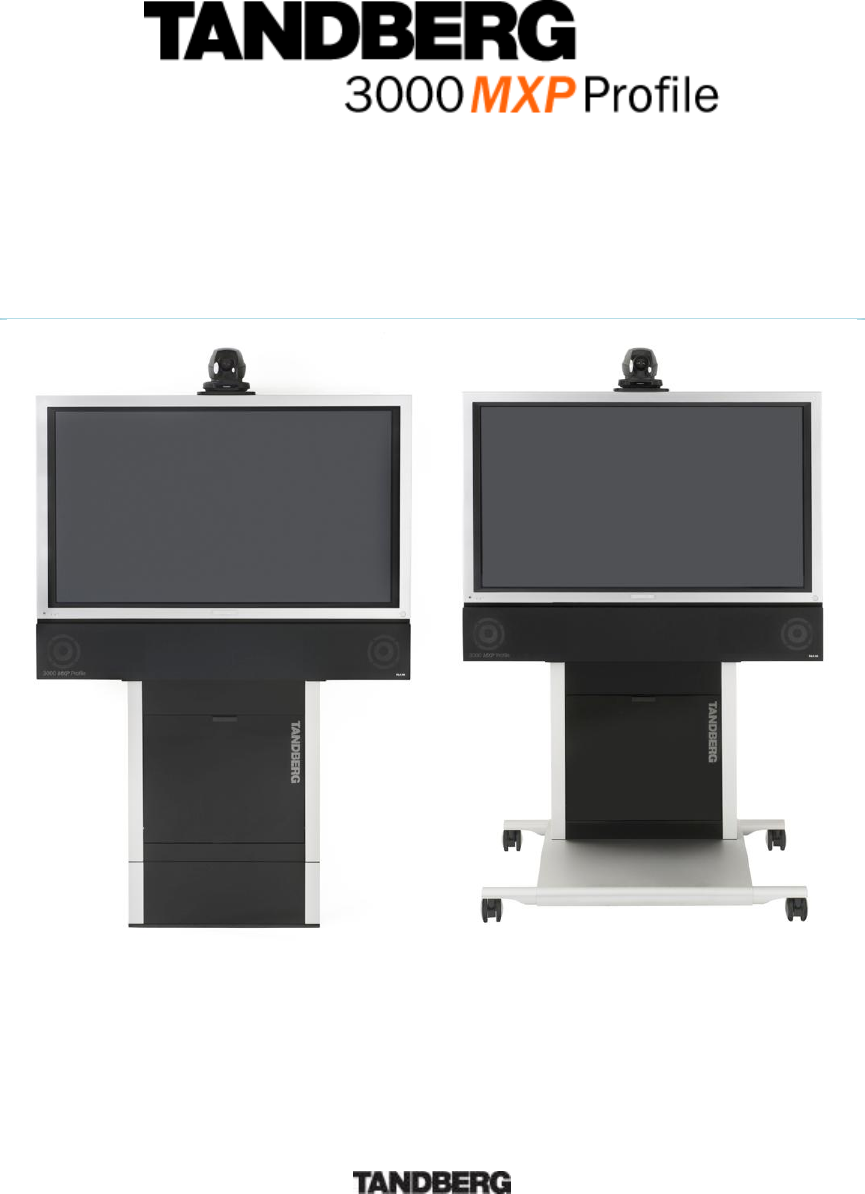
TANDBERG 3000 MXP
ii
Trademarks and Copyright
All rights reserved. This document contains information that is proprietary to TANDBERG. No part
of this publication may be reproduced, stored in a retrieval system, or transmitted, in any form, or
by any means, electronically, mechanically, by photocopying, or otherwise, without the prior
written permission of TANDBERG. Nationally and internationally recognized trademarks and
trade names are the property of their respective holders and are hereby acknowledged.
This product includes software developed by the OpenSSL Project for use in the OpenSSL
Toolkit. Copyright © 1998-2002 The OpenSSL Project. All rights reserved.
This product includes cryptographic software written by Eric Young. Copyright © 1995-1998 Eric
Young. All rights reserved.
Contains iType™ from Agfa Monotype Corporation.
ICU License - ICU 1.8.1 and later COPYRIGHT AND PERMISSION NOTICE Copyright (c) 1995-
2003 International Business Machines Corporation and others All rights reserved.
Disclaimer
The information in this document is furnished for informational purposes only, is subject to
change without prior notice, and should not be construed as a commitment by TANDBERG. The
information in this document is believed to be accurate and reliable; however TANDBERG
assumes no responsibility or liability for any errors or inaccuracies that may appear in this
document, nor for any infringements of patents or other rights of third parties resulting from its
use. No license is granted under any patents or patent rights of TANDBERG.
This document was written by the Research and Development Department of TANDBERG,
Norway. We are committed to maintain a high level of quality in all our documentation. Towards
this effort, we welcome you to Contact us with comments and suggestions regarding the content
and structure of this document.
COPYRIGHT © 2005, TANDBERG

User Manual
iii
Environmental Issues
TANDBERG visual communication products significantly reduce the need for travel and thereby
help reduce various types of pollution. TANDBERG recommends the use of low energy
peripherals, such as EnergyStar™ monitors. Thank you for buying a TANDBERG product.
Battery handling
The batteries for the Remote Control are Long Life Alkaline batteries, which means you will need
fewer batteries, further benefiting the environment. Please follow the guidelines on the packing
material for handling and disposal instructions for the batteries.
Waste handling
This TANDBERG product contains no consumables that require disposal. You should retain the
packaging materials in case future shipment is necessary. Please contact your local authorities
for information on waste handling and recycling regulations for electronic products.
Production of products
Our factories employ the most efficient environmental methods for reducing waste and pollution.
Our designers do their best to ensure TANDBERG products are highly recyclable.
Digital User Manuals
TANDBERG is pleased to announce that it has replaced the printed versions of its User Manuals
with a digital CD version. Instead of a range of different user manuals, there is now one CD which
can be used with all TANDBERG MXP products. The CD contains a variety of supported
languages. The environmental benefits of digital manuals are significant, from saving paper, to
reduced weight for shipping. Even the CD itself is recyclable. Not only are they more ecological,
digital manuals are more user friendly. A simple web-based search feature helps users directly
access the information they need. In addition, this TANDBERG video system now has an intuitive
on-screen help function, which provides a range of useful features and tips. If desired, the user
manuals on the CD can still be printed locally.
TANDBERG 3000 MXP
iv
Operator Safety Summary
For your protection, please read these safety instructions completely before operating the
equipment and keep this manual for future reference. The information in this summary is intended
for operators. Carefully observe all warnings, precautions and instructions both on the apparatus
and in the operating instructions.
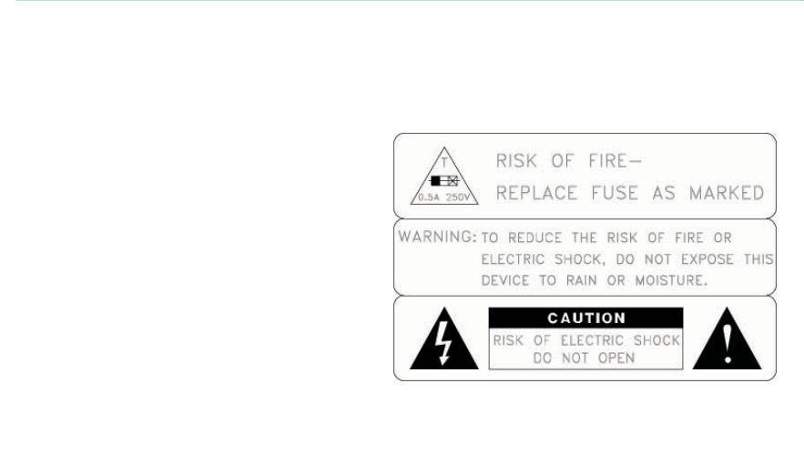
Equipment Markings
The lightning flash symbol within an
equilateral triangle is intended to alert the
user to the presence of uninsulated
“dangerous voltages” within the product’s
enclosure that may be of sufficient
magnitude to constitute a risk of electrical
shock.
The exclamation mark within an equilateral
triangle is intended to alert the user to the
presence of important operating and
maintenance (servicing) instructions
accompanying the equipment.
Warnings
Water and moisture - Do not operate the equipment under or near water - for example
near a bathtub, kitchen sink, or laundry tub, in a wet basement, or near a swimming pool
or in areas with high humidity.
Cleaning - Unplug the apparatus from the wall outlet before cleaning or polishing. Do not
use liquid cleaners or aerosol cleaners. Use a lint-free cloth lightly moistened with water
for cleaning the exterior of the apparatus.
Ventilation - Do not block any of the ventilation openings of the apparatus. Install in
accordance with the installation instructions. Never cover the slots and openings with a
cloth or other material. Never install the apparatus near heat sources such as radiators,
heat registers, stoves, or other apparatus (including amplifiers) that produce heat.
Grounding or Polarization - Do not defeat the safety purpose of the polarized or
grounding-type plug. A polarized plug has two blades with one wider than the other. A
grounding type plug has two blades and a third grounding prong. The wide blade or third
prong is provided for your safety. If the provided plug does not fit into your outlet, consult
an electrician.
Power-Cord Protection - Route the power cord so as to avoid it being walked on or
pinched by items placed upon or against it, paying particular attention to the plugs,
receptacles, and the point where the cord exits from the apparatus.
Attachments - Only use attachments as recommended by the manufacturer.
Accessories - Most systems should only be used with a cart, stand, tripod, bracket, or
table specified by the manufacturer, or sold with the apparatus. When a cart is used, use
caution when moving the cart/apparatus combination to avoid injury from tip-over.
Lightning - Unplug this apparatus during lightning storms or when unused for long periods
of time.
User Manual
v
ISDN cables - CAUTION - To reduce the risk of fire, use only No. 26 AWG or larger
telecommunication line cord.
Servicing - Do not attempt to service the apparatus yourself as opening or removing
covers may expose you to dangerous voltages or other hazards, and will void the
warranty. Refer all servicing to qualified service personnel.
Damaged Equipment - Unplug the apparatus from the outlet and refer servicing to
qualified personnel under the following conditions:
When the power cord or plug is damaged or frayed
If liquid has been spilled or objects have fallen into the apparatus
If the apparatus has been exposed to rain or moisture
If the apparatus has been subjected to excessive shock by being dropped, or the
cabinet has been damaged
If the apparatus fails to operate in accordance with the operating instructions

TANDBERG 3000 MXP
vi
Contact us
If you have any questions, comments or suggestions, please see the Online Support section at
www.tandberg.net.
It is also possible to send a fax or mail to the attention of:
Product and Sales Support
TANDBERG
P.O. Box 92
1325 Lysaker
Norway
Tel: +47 67 125 125
Fax: +47 67 125 234
User Manual
vii
Table of Contents
1 Introduction............................................................................................................................... 1
1.1 At a Glance ............................................................................................................................ 4
1.2 Menu Structure ...................................................................................................................... 6
2 Installation ................................................................................................................................ 8
2.1 Unpacking and Mounting ....................................................................................................... 9
2.2 Connecting Cables............................................................................................................... 11
2.3 Monitor Configuration........................................................................................................... 12
2.4 System Configuration........................................................................................................... 13
3 General Use ........................................................................................................................... 16
3.1 The Welcome Screen .......................................................................................................... 17
3.2 Using the Remote Control.................................................................................................... 18
3.2.1 Navigation ................................................................................................................ 22
3.2.2 Selfview.................................................................................................................... 23
3.2.3 Layout ...................................................................................................................... 25
3.2.4 Mic Off...................................................................................................................... 26
3.2.5 Volume + and - ........................................................................................................ 27
3.2.6 Number and Letter keys........................................................................................... 28
3.2.7 Touch Tones............................................................................................................ 29
3.3 On-screen Indicators............................................................................................................ 30
3.4 Using the Menu.................................................................................................................... 32
3.5 Make a Call .......................................................................................................................... 34
3.5.1 Place Video Call....................................................................................................... 35
3.5.2 Place Telephone Call............................................................................................... 36
3.5.3 Add Call ................................................................................................................... 37
3.5.4 Call Settings............................................................................................................. 39
3.5.5 Streaming................................................................................................................. 40
3.6 Answer an incoming call ...................................................................................................... 42
3.7 End Call................................................................................................................................ 43
3.8 Standby................................................................................................................................ 44
3.8.1 Delay Standby for 1 hour ......................................................................................... 45
3.8.2 Delay Standby for 3 hours ....................................................................................... 46
3.8.3 Do Not Disturb ......................................................................................................... 47
3.9 Phone Book.......................................................................................................................... 48
3.9.1 Call Log.................................................................................................................... 49
3.9.2 My Contacts ............................................................................................................. 50
3.9.3 Global Contacts ....................................................................................................... 57
3.10 Camera Control.................................................................................................................. 61
3.10.1 Move Camera .......................................................................................................... 62
3.10.2 Far End Control........................................................................................................ 63
3.10.3 Camera Presets....................................................................................................... 64
3.10.4 TANDBERG Tracker................................................................................................ 65
3.10.5 Picture Control ......................................................................................................... 66
3.10.6 Camera Tracking ..................................................................................................... 67
3.11 Presentation....................................................................................................................... 68
3.11.1 Presentation Key...................................................................................................... 69
3.11.2 Presentation Menu................................................................................................... 70
3.11.3 PC Presenter (DVI/XGA Input) ................................................................................ 71
3.11.4 PC Soft Presenter and VNC .................................................................................... 72
3.11.5 Dual Stream (DuoVideoTF/H.239)........................................................................... 73
3.11.6 Take New Snapshot................................................................................................. 74
3.11.7 Display Snapshot..................................................................................................... 75
TANDBERG 3000 MXP
viii
3.12 Conference Services.......................................................................................................... 76
3.12.1 Request Floor and Release Floor............................................................................ 79
3.12.2 Conference Layout................................................................................................... 80
3.12.3 Terminal Names....................................................................................................... 81
3.12.4 Chair Control............................................................................................................ 82
3.12.5 Assign Floor and Release Floor from Participant .................................................... 83
3.12.6 View Site and End View........................................................................................... 84
3.12.7 Disconnect Participant ............................................................................................. 85
3.12.8 Terminate Meeting................................................................................................... 86
3.12.9 More about MultiSite (embedded MCU) .................................................................. 87
3.13 Control Panel ..................................................................................................................... 88
3.13.1 Diagnostics .............................................................................................................. 89
3.13.2 System Information.................................................................................................. 90
3.13.3 Channel Status ........................................................................................................ 91
3.13.4 Call Status................................................................................................................ 92
3.13.5 System Selftest........................................................................................................ 93
3.13.6 View Administrator Settings..................................................................................... 94
3.13.7 IP Address Conflict Check ....................................................................................... 98
3.13.8 Warnings.................................................................................................................. 99
3.13.9 Text Chat ............................................................................................................... 101
3.13.10 Audio Demo....................................................................................................... 102
3.13.11 Administrator Settings ....................................................................................... 103
3.13.12 Restart ............................................................................................................... 104
3.13.13 User Guide ........................................................................................................ 105
4 Administrator Settings .......................................................................................................... 106
4.1 General Settings ................................................................................................................ 107
4.1.1 Language ............................................................................................................... 108
4.1.2 System Name ........................................................................................................ 109
4.1.3 International Name................................................................................................. 110
4.1.4 Auto Answer........................................................................................................... 111
4.1.5 Phone Book Settings ............................................................................................. 112
4.1.6 External Services Settings..................................................................................... 113
4.1.7 Permissions ........................................................................................................... 114
4.1.8 Screen Settings...................................................................................................... 116
4.1.9 Software Options ................................................................................................... 122
4.1.10 Date and Time Settings ......................................................................................... 123
4.2 Menu Settings .................................................................................................................... 124
4.2.1 Input Editor Language............................................................................................ 125
4.2.2 Menu Timeout In Call............................................................................................. 126
4.2.3 Menu on TV ........................................................................................................... 127
4.2.4 Menu on PC ........................................................................................................... 128
4.2.5 Balloon Help........................................................................................................... 129
4.2.6 Administrator Password......................................................................................... 130
4.2.7 Kiosk Mode Settings .............................................................................................. 131
4.2.8 Startup ................................................................................................................... 134
4.2.9 Icons....................................................................................................................... 136
4.3 Presentation Settings......................................................................................................... 137
4.3.1 Presentation Start .................................................................................................. 138
4.3.2 H.239...................................................................................................................... 139
4.3.3 Startup Video Source............................................................................................. 140
4.3.4 Presentation Source .............................................................................................. 141
4.3.5 Snapshot Source ................................................................................................... 142
4.3.6 Auto-Display Snapshot .......................................................................................... 143
4.3.7 PIP Appearance..................................................................................................... 144
4.3.8 PIP Placing ............................................................................................................ 145
4.3.9 VNC Settings ......................................................................................................... 146
User Manual
ix
4.4 Call Quality......................................................................................................................... 147
4.4.1 Video Algorithm...................................................................................................... 148
4.4.2 Audio Algorithm...................................................................................................... 149
4.4.3 AAC-LD 128kbps (stereo audio)............................................................................ 150
4.4.4 Natural Video ......................................................................................................... 151
4.4.5 Max Upstream Rate (kbps).................................................................................... 152
4.4.6 Video Quality.............................................................. Error! Bookmark not defined.
4.4.7 Default Call Settings .............................................................................................. 156
4.5 Audio.................................................................................................................................. 159
4.5.1 Inputs ..................................................................................................................... 160
4.5.2 Outputs .................................................................................................................. 164
4.5.3 Echo Control .......................................................................................................... 166
4.5.4 Stereo Settings ...................................................................................................... 167
4.5.5 Audio Levelling (AGC) ........................................................................................... 169
4.5.6 Alert Tones and Volume ........................................................................................ 170
4.6 Video.................................................................................................................................. 171
4.6.1 Camera Tracking Mode ......................................................................................... 172
4.6.2 MCU Status Line.................................................................................................... 173
4.6.3 Floor to Full Screen................................................................................................ 174
4.6.4 Web Snapshots...................................................................................................... 175
4.6.5 MultiSite Picture Mode........................................................................................... 176
4.6.6 Video Name ........................................................................................................... 178
4.7 Security .............................................................................................................................. 179
4.7.1 Encryption .............................................................................................................. 180
4.7.2 Encryption Mode.................................................................................................... 181
4.7.3 Passwords ............................................................................................................. 182
4.8 Network.............................................................................................................................. 183
4.8.1 ISDN-BRI Settings ................................................................................................. 184
4.8.2 LAN Settings .......................................................................................................... 186
4.8.3 Network Profiles..................................................................................................... 205
4.8.4 Data Port................................................................................................................ 206
4.8.5 Camera Port Settings............................................................................................. 207
4.8.6 Restore Default Settings........................................................................................ 208
5 Peripheral Equipment........................................................................................................... 209
5.1 Interfaces ........................................................................................................................... 210
5.1.1 Video...................................................................................................................... 210
5.1.2 Audio...................................................................................................................... 214
5.1.3 Network.................................................................................................................. 216
5.1.4 Data port ................................................................................................................ 216
5.1.5 Camera Port........................................................................................................... 218
5.2 Document Camera............................................................................................................. 220
5.3 DVD / VCR......................................................................................................................... 221
5.4 Additional Cameras............................................................................................................ 223
5.5 Additional Microphones...................................................................................................... 224
5.6 The TANDBERG DNAM and Speakers............................................................................. 225
5.7 Stereo Speaker Kit............................................................................................................. 229
5.8 Telephone Add-On............................................................................................................. 231
5.9 Dual Monitor....................................................................................................................... 232
5.10 XGA Monitors and Projectors .......................................................................................... 233
5.11 VESA Display Power Management ................................................................................. 234
5.12 Digital Monitor Power Management................................................................................. 235
5.13 Extended Display Identification Data (EDID) ................................................................... 236
6 Appendices........................................................................................................................... 238
6.1 Appendix 1 ......................................................................................................................... 239
6.2 Appendix 2 ......................................................................................................................... 242
6.3 Appendix 3 ......................................................................................................................... 245
TANDBERG 3000 MXP
x
6.4 Appendix 4 ......................................................................................................................... 246
6.5 Appendix 5 ......................................................................................................................... 248
6.6 Appendix 6 ......................................................................................................................... 251
6.7 Appendix 7 ......................................................................................................................... 252
6.8 Appendix 8 ......................................................................................................................... 253
6.9 Appendix 9 ......................................................................................................................... 254
6.10 Appendix 10 ..................................................................................................................... 255
6.11 Appendix 11 ..................................................................................................................... 256
6.12 Appendix 12 ..................................................................................................................... 258
6.13 Appendix 13 ..................................................................................................................... 260
6.14 Appendix 14 ..................................................................................................................... 261
6.15 Appendix 15 ..................................................................................................................... 263
6.16 Appendix 16 ..................................................................................................................... 269
Appendix 17 ............................................................................................................................. 270
6.17 Appendix 18 ..................................................................................................................... 275
7 Glossary ............................................................................................................................... 277
8 Index..................................................................................................................................... 287

1
1 Introduction
Audio Quality
High-performance audio provides a richer, more complete visual communication experience. The
MPEG4 AAC-LD standard is used to provide true standards-based CD-quality, stereo audio.
Users can record and send stereo audio from stereo presentation and playback sources using
PCs, DVDs and VCRs using the proper cables.
NEW Eliminate disturbance from GSM mobile phones and Blackberry devices
Video Quality
Features which ensure high quality video includes:
Natural VideoTF which provides a 60 fields per second true interlaced picture.
Support for H.264 in MultiSite, DuoVideo/H.239 and encryption.
SXGA input and XGA output through DVI-I (analog or digital).
H.264 video compression up to 2Mbps.
Support for native 16:9 Wide XGA monitors by increasing the resolution to 1280x768
(WXGA).
Automatic use of WXGA format when ”VGA Monitor Format” is set to Wide.
NEW HD Support on all TANDBERG MXP systems with a DVI input and output
NEW High quality video and native 16:9 formats
Network
The system supports videoconferencing via both IP and ISDN networks. The bandwidth
capabilities are:
up to 2Mbps* per call
up to 2.3Mbps* total for a MultiSite conference.
SIP support, for both point-to-point and MultiSite*.
If channels are dropped during a videoconferencing session, downspeedingTF automatically
maintains connections without interruption.
Security
Secure ConferenceTF provides embedded encryption for both Point-to-Point and MultiSite call and
ensures both privacy and security.
The system is delivered with integrated Expressway™ firewall traversal technology. When used
together with a TANDBERG Border Controller it enables:
Secure and seamless traversal of ANY firewall.
No missing features when traversing the firewall – works with H.264, MPEG4 audio,
encryption.
TANDBERG 3000 MXP
2
Outside systems, such as home offices, to be part of the enterprise dial plan.
Dialing to systems by URI, e.g. user@company.com.
NEW
H.460, ITU Standardized firewall traversal, support
NEW
High security network authentication (802.1x)
MultiSite*
The embedded MultiSiteTF functionality can cater for up to 4 video sites and 3 audio sites and
supports screen layouts such as VoiceSwitched, AutoSplit, 4 Split and 5+1 Split. The optional
embedded MultiSite functionality supports any combination of ISDN and IP participants in a
conference (up to the total).
Superior quality and reliability in MultiSite calls is ensured by the systems support for:
DuoVideo/H.239 to provide for presenting full PC resolution information
AES and DES encryption to provide security
H.264 video algorithm to provide the best video at all bandwidths
Rate matchingTF to support different call rates for all sites in a MultiSite
TranscodingTF to support different protocols for all sites in a MultiSite.
The TANDBERG videoconferencing system can also be used as an audio telephone bridge
(assuming ISDN connection(s)).
Presentations
The Natural Presenter Package* (NPP) makes it possible to include PC presentations in
videoconferences and comprises:
Digital ClarityTF which transmits exceptionally high-quality, native resolution video.
Duo VideoTF/H.239 which allows participants at the far end to simultaneously watch a
presenter on one screen and a live PC presentation in native resolution on a second
monitor (up to SXGA on compatible monitors).
PC PresenterTF which allows a PC connection via standard DVI/VGA cable supporting up
to SXGA resolution.
PC SoftPresenterTF which shows PC images via a LAN connection supporting XGA
resolution.
Auto Layout to automatically choose the best layout for the call.
PC Zoom which allows the native resolution PC image to be zoomed in/out with the
remote control to get SXGA resolution.
Users can display video and presentations in the best layout based on the situation. Supported
screen layouts are:
Picture in Picture (PiP)
Picture outside Picture (PoP)
Side by Side
User interfaces
A web-interface to the codec provides:
System management, diagnostics and software uploads.
Text chat/closed captioning.

Introduction
3
Unicast Streaming – which allows broadcasting of audio/video via an IP network to a
single compatible client (RealMedia™ or Apple Quicktime™) or streaming server.
The On-Screen Menu:
Provides an easy interface for first-time users with symbols and descriptions.
Builds upon the familiar current interface.
NEW
Enhanced language support with Asian and non-Latin character text input in the
menu for local language system names
NEW
Support for new optional remote control
improved usability
separate ordering
NEW Simplified on-screen menu, Kiosk Mode, for special purposes
The remote control has a simplified look and feel, an auto system wake-up when picked up, and
large, easy-to-read keys.
Interoperability
The TANDBERG 3000 MXP Profile is worldwide compatible with other standards-based
videoconferencing systems.
* - optional feature. To check which options are installed, select Control Panel - System Information in the menu.
TF - TANDBERG First
TANDBERG 3000 MXP
4
1.1 At a Glance
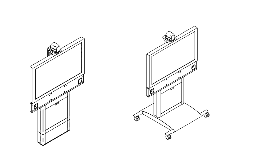
TANDBERG 3000 MXP Profile Wall
Mount TANDBERG 3000 MXP Profile Roll About
Camera
The camera cables are put through the camera bracket, which is then mounted on top of the
monitor. The main camera is fastened to the camera bracket. The main camera includes a high
quality color camera with a fast pan/tilt/zoom action. The main camera is controlled by the
system’s infra-red remote control and operates pan/tilt, focus and zoom.
Monitors
The monitor displays the far-end and near-end videoconferencing sites in addition to the menus,
video from connected video sources and high-resolution images.
Note that the TANDBERG 3000 MXP Profile is shipped with different monitors depending on
which configuration is ordered. There are two
different configurations of the system: 32”, which has a 32” LCD monitor and the 43”
configuration, which has a 43” plasma monitor. Hence, the
pictures/drawings used in this manual might differ from the actual monitor model shipped with the
system.
Codec
The codec is the heart of the system. Its main task is the compression of outgoing video, audio
and data, the transmission of this information to the far end, and the decompression of the
Introduction
5
incoming information. The name codec comes from a combination of the two words compression
and decompression.
Column and Base
The Roll About system is easily movable due to large wheels and handles, at the back of the
monitor. The codec is located inside the bracket assembly behind the monitor. Inside the column
assembly, there is room for additional equipment, e.g. a VCR or a DVD player.
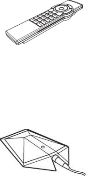
Remote Control
The remote control is used to control all functions of the system. The remote control uses 4 AAA
batteries. The system will tell you when batteries are running low. Change the batteries at the
back of the remote control.
The reach of the remote control signal is 20 meters (65 feet). The remote control IR receiver is
located on the WAVE II camera. For users working in an open environment with multiple systems
deployed, this can cause other systems to respond to your remote control. Use the little white
switch placed under the batteries to change the reach of the signal from 20 meters (65 feet) to 2
meters (6.5 feet). This will prevent you from unintentionally controlling another video system when
you control your own system.
If the screen saver is activated (black monitor), wake up the system by picking up the remote
control.
Microphone
The high quality table microphone is designed to be placed on a table during a videoconference.
Up to three microphones can be connected. The ideal location for the microphone is on a flat
surface at least 2m (6.5 ft) from the front of the system. The microphone cable should always
point towards the system. The system will automatically equalize sound levels. Loud and soft
voices are picked up and transmitted to the far end at approximately the same level.
TANDBERG 3000 MXP
6
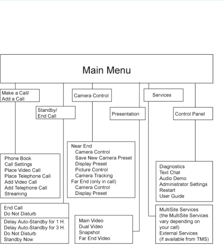
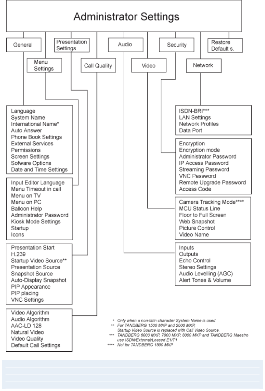
1.2 Menu Structure
The menu structure is divided into two parts. The Main Menu is available for all users and
contains all the functionality of the system. The Administrator Menu contains all the settings of the
system. The Administrator Settings are accessible from the Main Menu by selecting Control
Panel and Administrator Settings. Making changes to the Administrator Settings will change the
behavior of the system. The menu structure for Main Menu and Administrator Settings is shown
below.
Introduction
7
Note that the system features and menu settings may vary depending on network selection
and software package.

8
2 Installation
Precautions:
Never install communication wiring during a lightning storm.
Never install jacks for communication cables in wet locations unless the jack is
specifically designed for wet locations.
Never touch uninstalled communication wires or terminals unless the telephone line has
been disconnected at the network interface.
Use caution when installing or modifying communication lines.
Avoid using communication equipment (other than a cordless type) during an electrical
storm. There may be a remote risk of electrical shock from lightning.
Do not use the communication equipment to report a gas leak in the vicinity of the leak.
Always connect the product to an earthed socket outlet.
The socket outlet shall be installed near to the equipment and shall be easily accessible.
Never install cables without first switching the power OFF.
1TR6 network type is not approved for connection directly to the telecommunications
network. This network type is only to be used behind a PABX.
This product complies with directives: LVD 73/23/EC, EMC 89/366/EEC, R&TTE 99/5/EEC
Installation
9
2.1 Unpacking and Mounting
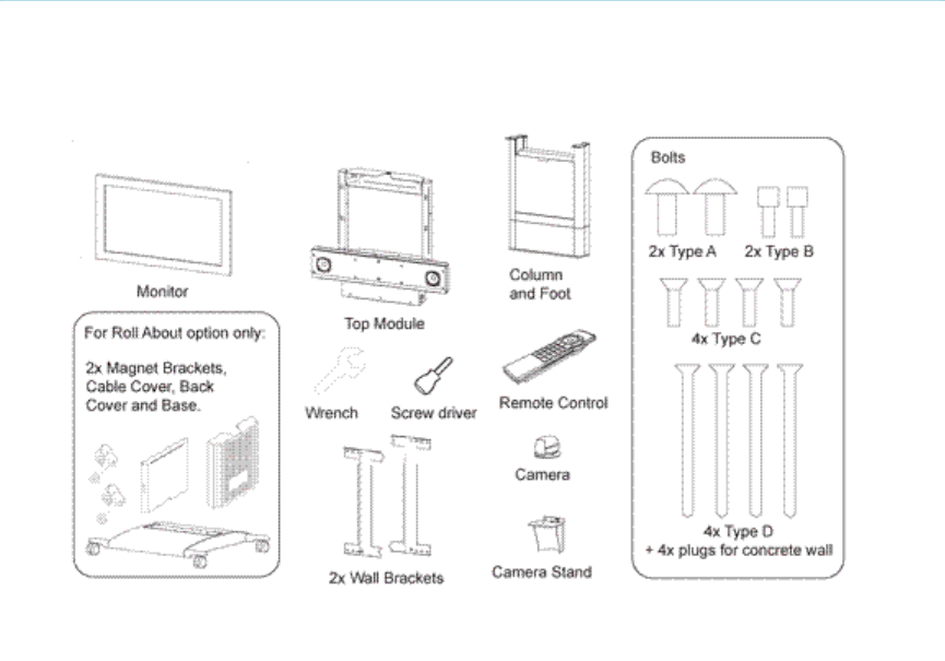
Unpacking
To avoid damage to the unit during transportation the system is delivered as separate
components:
System
Column and Foot
Base, optional
High quality monitor
Wall Brackets
Camera
Camera stand
The Accessories box contains the following:
Screws
ISDN cables
Table Microphone
Remote Control
Documentation
Mounting
Please refer to the Installation sheet provided with the system for details on how to mount the
TANDBERG 3000 MXP Profile.

TANDBERG 3000 MXP
10
Note! The camera should be aligned with the front edge of the monitor to ensure that the IR-
sensor in the camera can pick up the signals from the remote control.

Installation
11
2.2 Connecting Cables
All cables needed for a standard configuration are already connected to the codec. Connect
these cables to their respective parts of the system.
1. Power cables
Connect the power cable to an electrical distribution socket.
2. Monitor cables
Connect the DVI cable to the input on your monitor.
3. Microphone cables
Connect the microphone cable to the microphones.
4. Camera cable
Connect the camera cable labeled “Main Cam” to the S-Video connector on the camera.
Connect also the control cable labeled “Camera Control” between the RJ-45 on the camera,
and the Camera Port on the codec.
5. PC cable
Connect the PC cable to the PC.
6. ISDN cables
Connect the ISDN cables to the ISDN sockets (S/T interface) provided by the network provider.
The main ISDN number will be that number associated with the socket to which ISDN cable
number 1 has been connected.
Note! The system does not have a built-in network terminator. If wall socket provides an
ISDN U-interface, an NT1 between your system and the ISDN line is needed, see Appendix
10 for more information.
7. LAN cable
To connect the system to a Local Area Network (LAN), connect the cable labeled "LAN
Ethernet" to a suitable Ethernet port on the LAN.

TANDBERG 3000 MXP
12
2.3 Monitor Configuration
The monitor is pre-configured and only needs to be switched on.
Installation
13
2.4 System Configuration
The system must be configured for each installation. Configuration settings can be made via the
system menu.
Navigate through the menu system using the arrow keys and OK. Remember to press the Save
button on the bottom of each menu to save the changes. Press Cancel (x) to return to the
previous Menu. See General Use for more information about how to use the menus and the
remote control.
General configuration:
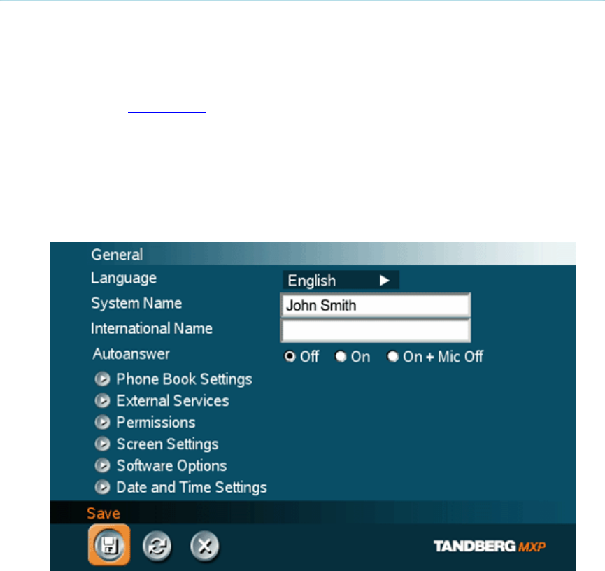
1. Open the General Settings menu
Press OK/Menu to open the Main Menu, if not already displayed. Select Control
Panel - Administrator Settings - General to open the General Settings menu.
2. Language
Press OK in the Language field and select the desired language from the list.
3. System Name / International Name*
Enter a name in the System Name field using the number keys on the remote control,
in the same way as with a mobile or cellular phone. Hold down the # key for one
second to switch back and forth from numbers to alpha characters.
4. Dual Monitor
If using one monitor, set Dual Monitor to "Off".
5. Auto Answer, Phone Book Settings, External Services Settings and
Permissions
TANDBERG 3000 MXP
14
These settings may be left unchanged if no special needs are required. See chapter
General Settings for more information.
6. Screen Settings
When using wide screen (16:9) monitors, set TV Monitor Format to Wide (16:9).
TANDBERG also recommends setting Picture Layout to Picture outside Picture when
using 16:9 monitors. Picture outside Picture provides a display layout optimized for
wide screen monitors. The display layout may be changed at any time using the
Layout button on the remote control.
7. Software Options
This menu item will display the currently installed options (such as MultiSite,
Presenter and high bandwidth options). To activate any
purchased software option for the system, an option key must be obtained and then
entered into the Software Options menu (see paperwork accompanying the system
for option keys). The MultiSite and Presenter option keys should be entered under
“New Option Key”. Any bandwidth option keys should be entered under “New
Bandwidth Key”. You may need to restart the system for options to take effect. For
more information on these options, please contact your TANDBERG representative.
8. Date and Time Settings
Select your preferred Date and Time Settings.
9. Save changes
Remember to select the on-screen Save icon on the bottom of each menu (highlight
using arrows and use the OK button to select) to save the changes you may have
made.
Network configuration:
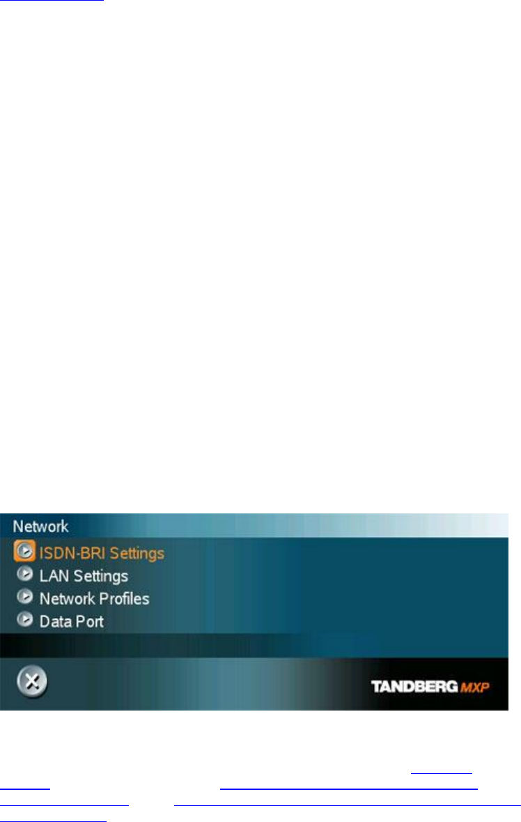
1. Open the Network menu
Press OK/Menu to open the Main Menu, if not already displayed. Select Control
Panel - Administrator Settings - Network to open the Network menu.
2. ISDN configuration
Set the Network type to the desired network. Specify the settings for the selected
network in the relevant menu. For details, follow the instructions in ISDN-BRI
Settings. See also the examples in Appendix 9: Connecting the system to the
Switched 56 network and in Appendix 10: Connecting the system to ISDN using NT1
network adapters.
3. LAN configuration

Installation
15
Select LAN Settings in the Network menu and specify the necessary LAN settings
according to the instructions from your LAN administrator. For details, follow the
instructions in LAN Settings. If there is an H.323 Gatekeeper present on your LAN,
refer to H.323 Settings as well.
4. Network Profiles
Please refer to Network Profiles for details
5. Data Port
Please refer to Data Port for details
6. Save changes
Remember to save any changes made in the menu by selecting the Save button on
the Menu line and pressing OK.
* This field is only visible if the system name contains Asian and non-Latin character text input.

16
3 General Use
Wake up the system
When the system is not in use, it is in standby mode and the screen is black. This is to help
protect the monitor display. Wake up the system by picking up the remote control. An incoming
call or pressing any key on the remote control will also wake up the system.
If the system does not respond:
Make sure that the system is switched on by using the On/Off switch located at the rear
of the Codec.
Verify that your monitor is switched on. This is normally done by pushing the power
button on the front of the monitor depending on monitor type. Please reference the user
guide for the monitor that was shipped with your system.
General Use
17
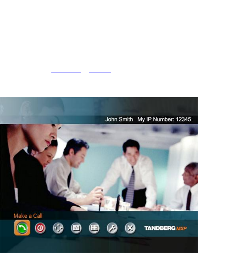
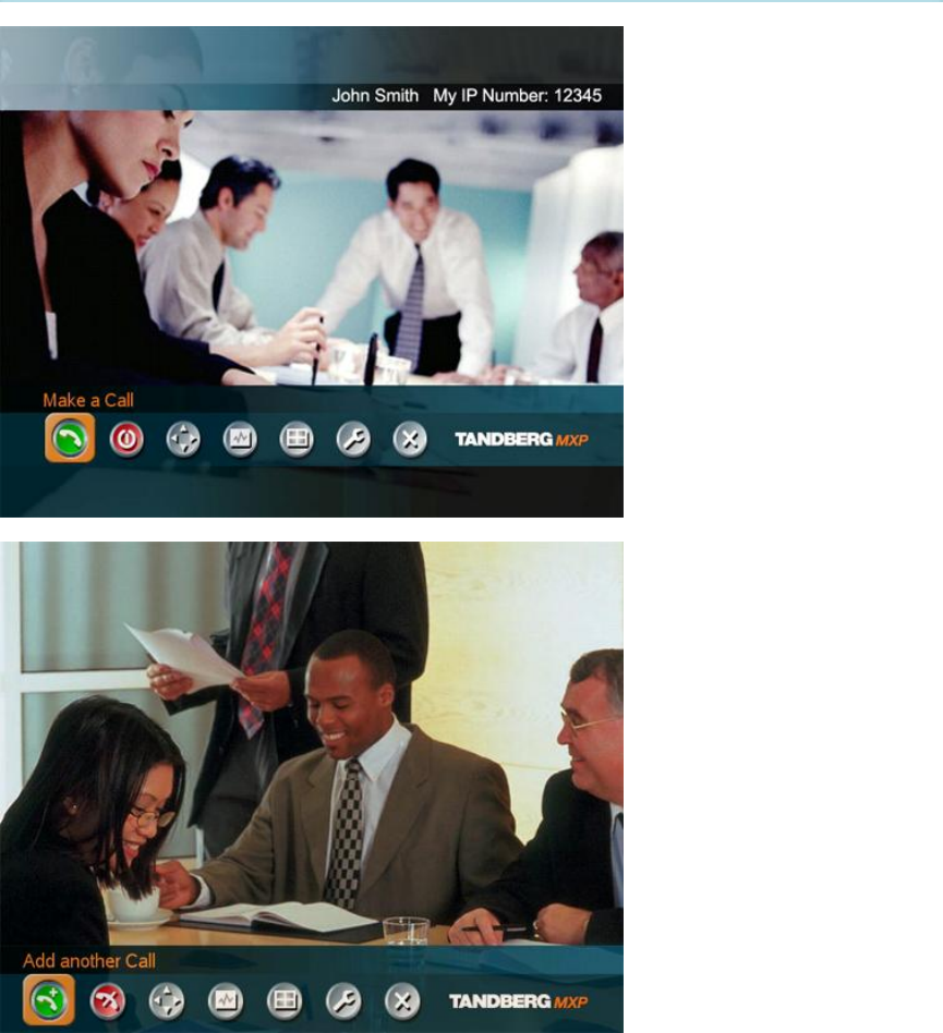
3.1 The Welcome Screen
When the system is switched on, the welcome screen will be displayed. The welcome screen
presents the menu and displays your main camera image in the background (display main
camera is the default setting). The ISDN/IP numbers and the system name are displayed in the
upper right corner. The ISDN Number and IP Number are the dial-in numbers of the system.
The welcome screen provides you with the most important system information:
System Name
Your ISDN Number
Your IP Address or IP Number
Indications of Missed Calls or Warnings if any
It is possible to customize the text on the welcome screen. See Menu Settings for how to edit the
welcome text.
TANDBERG 3000 MXP
18
3.2 Using the Remote Control
The system is controlled with a remote control. Think of the remote control as a mobile phone
with number keys and call keys. Use the arrow keys and press OK to navigate through the
menus. The system’s most commonly used functions are also accessible directly from the remote
control. The Infra Red (IR) sensor for the remote control is located in front of the WAVE II
Camera. There is also a second IR-sensor located in the front of the Codec itself, which will be
automatically enabled if the WAVE II Camera is not connected.
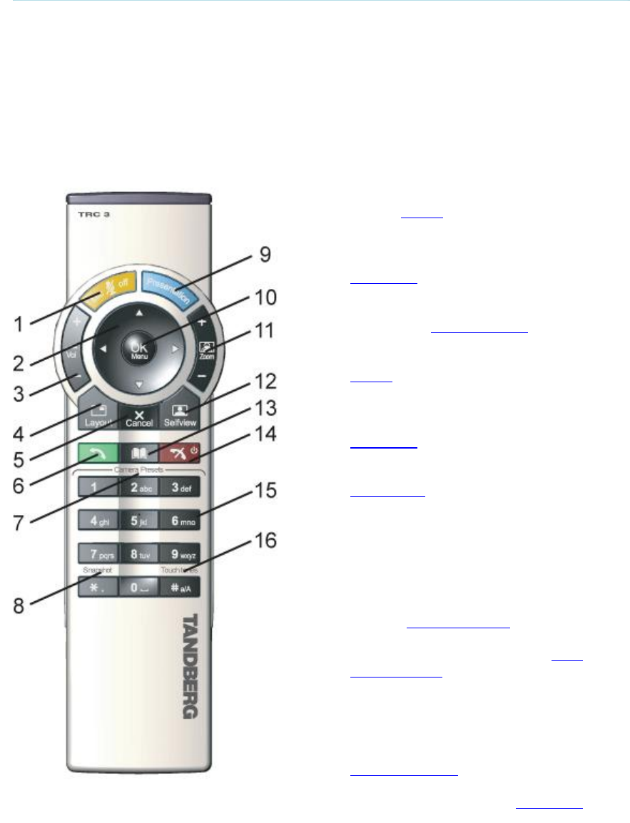
The remote control (TRC 3)
1. Mic Off turns your microphone on and
off, see Mic off.
2. Arrow keys are used for navigation in
the menu and for moving the camera*
when the menu is hidden, see
Navigation.
3. Volume + and – adjusts the Codec
volume only and not the monitor's
volume, see Volume + and -.
4. The Layout key toggles between full
screen and different display layouts, see
Layout.
5. Cancel takes you back one step in the
menu system. Use Cancel to delete
characters in an input field, see
Navigation. Press and hold the Cancel
key for 1 second to close the menu.
6. Press the Call key to place a call, see
Make a Call.
7. Camera presets define specific camera
positions. Move the camera to the
desired position and press and hold a
number key for 1 second to save the
current camera position to that number
key. To activate a preset whilst in a call,
simply press and release that number
key, see Camera Presets.
8. Snapshot takes a snapshot of your video
only while you are in a call, see Take
New Snapshot.
9. The Presentation key switches to a
predefined presentation source. If the
Presentation key is held down for 1
second then the Presentation video
sources menu will appear, see
Presentation Key.
10. Press OK/Menu to show the menu and
to select menu items, see Navigation.

General Use
19
11. Use Zoom + and – to zoom the camera
in and out.*
12. Selfview displays your outgoing video.
Press Selfview again to turn selfview off,
see Selfview.
13. Use the Phone Book to store and recall
video contacts for easy placement of
calls, see Phone Book.
14. Use the red End Call key to end the
current call. Pressing this key when not
in a call will place the system in Standby
mode, see End Call and Standby.
15. Number/Letter keys function in the same
manner as with a mobile or cellular
phone, see Number and Letter keys.
16. Press Touch tones when you are in a
call and need to dial extension numbers
etc. (instead of presets). Press the
OK/Menu button to exit Touch Tones,
see Touch tones.
*This does not apply to all systems with small integrated cameras.
TANDBERG 3000 MXP
20
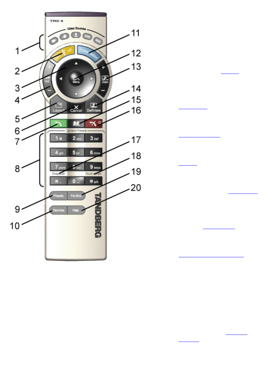
The remote control (TRC 4)**:
1. Change video source. If
possible, you will start open a
Dual Stream. Press the video
source button again to stop
the dual stream.
2. Mic Off turns your microphone
on and off, see Mic off.
3. Arrow keys are used for
navigation in the menu and for
moving the camera* when the
menu is hidden, see
Navigation.
4. Volume + and – adjusts the
Codec volume only and not
the monitor's volume, see
Volume + and -.
5. The Layout key toggles
between full screen and
different display layouts, see
Layout.
6. Cancel takes you back one
step in the menu system. Use
Cancel to delete characters in
an input field, see Navigation.
Press and hold the Cancel
key for 1 second to close the
menu.
7. Press the Call key to place a
call, see Make a Call.
8. Number/Letter keys function
in the same manner as with a
mobile or cellular phone, see
Number and Letter keys.
Camera presets define
specific camera positions.
Move the camera to the
desired position and press
and hold a number key for 1
second to save the current
camera position to that
number key. To activate a
preset whilst in a call, simply
press and release that
number key, see Camera
Presets.
9. Press Preset + a number to
activate a preset.
10. Press the Services button to
open the Services menu.
11. The Presentation key
switches to a predefined

General Use
21
presentation source. If the
Presentation key is held down
for 1 second then the
Presentation video sources
menu will appear, see
Presentation Key.
12. Press OK/Menu to show the
menu and to select menu
items, see Navigation.
13. Use Zoom + and – to zoom
the camera in and out.*
14. Selfview displays your
outgoing video. Press
Selfview again to turn selfview
off, see Selfview.
15. Use the Phone Book to store
and recall video contacts for
easy placement of calls, see
Phone Book.
16. Use the red End Call key to
end the current call. Pressing
this key when not in a call will
place the system in Standby
mode, see End Call and
Standby.
17. Snapshot takes a snapshot of
your video only while you are
in a call, see Take New
Snapshot.
18. Press Touch tones when you
are in a call and need to dial
extension numbers etc.
(instead of presets). Press the
OK/Menu button to exit Touch
Tones, see Touch tones.
19. Pressing Far End turns Far
End control on and off.
20. Press the Help button to open
the User Guide menu.
*This does not apply to all systems with small integrated cameras.
** Ordered separately
TANDBERG 3000 MXP
22
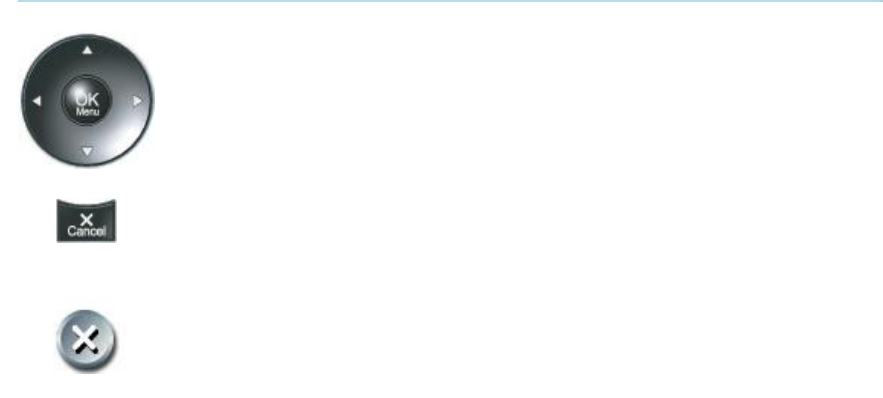
3.2.1 Navigation
Arrow keys and OK
Navigate in the menu with the arrow keys on the remote control. The
orange selector on screen shows the selected item. Press OK to select.
Cancel key
In the main menu, pressing Cancel (X) will hide the menu. If the menu is
hidden, bring it back with OK. In other menus, pressing Cancel (X) takes
you one step back. In an input field, pressing Cancel (X) will delete
characters/numbers to the left.
Back/Cancel button
The X button in the menu corresponds with the X key on the remote.

General Use
23
3.2.2 Selfview
The term “Selfview” means the outgoing image. In a normal call using the main camera, this is
the image of yourself. The Selfview button toggles the images between Far End, Selfview and
Dual Video (if any).
How to use Selfview:
1. Outside a call, pressing the Selfview button will switch between the near end video and a
black screen/logo on the main monitor.
2. In a point to point call, press the Selfview button once to switch from far end video to near
end video to see a full screen picture of the outgoing video. Press Selfview again to go
back to normal.
3. In a point to point call with a dual video stream, the dual stream is displayed in the big
picture. Press the Selfview button to toggle to the Near End picture, then the Far End
picture, and finally back to the dual stream.
The above behaviour is similar for both single monitor systems and dual monitor systems.
Selfview applies to the main monitor.
3.2.2.1 Local PC Display
When using the screen as your PC screen, it is recommended to set Local PC Display to On, see
Screen Settings. That implies that you can display your PC locally while having a
videoconference, and you can keep on working without having the Far End participant viewing
your PC screen.
Note that this applies to single monitor systems only.
It is also recommended to keep the Auto Layout setting On (default) to get a suitable layout when
toggling from Local PC Display mode to standard conference mode.
Use the Selfview button to toggle between Local PC Display mode and standard videoconference
mode. An indicator tells you that your PC image is displayed locally.

TANDBERG 3000 MXP
24
Example:
You are using the system as a PC and get an incoming call.
When the setting “Use Screen as Local PC monitor” is On, you will keep your PC image
displayed locally and the incoming call pops up in a PIP or as smaller images in a 1+3
layout, depending on your system. You will see Local PC displayed in the big picture
and Far End and/or Near End (your self) displayed in smaller pictures.
Press the Selfview button to switch to standard conference mode. The Local PC image
is no longer displayed and Far End is displayed in the big picture or full screen. Press
Selfview again to see Near End. Pressing Selfview a third time will bring back the Local
PC display mode.

General Use
25
3.2.3 Layout
The layout of the screen can either be shown as Picture in Picture (PIP) or Picture outside Picture
(POP) when displaying more than one video image. The behavior of the Layout button is
dependent on the Picture Layout setting in Screen Settings.
3.2.3.1 Picture in Picture
When Picture Layout is set to PIP, the Layout button makes it possible to see a second image in
a smaller view in one of the corners of the screen. The second image will be placed on top of the
main image. The user can decide in which corner the second image is to be displayed.
3.2.3.2 Picture outside Picture
When Picture Layout is set to POP, the Layout button makes it possible to see up to three images
in a composition optimized for wide screens. The second image can be displayed either as a
side-by-side the main image (1+1) or smaller images next to the main image (1+2 and 1+3).
Press the Layout button once to get side-by-side view (1+1). Press again to get the layouts 1+2
and 1+3, and finally go back to full screen view. You can also go back to full screen directly by
pressing and holding Layout for 1 second. It is recommended to use Picture outside Picture for
wide screen monitor systems.
3.2.3.3 Auto Layout
The system will automatically choose the best layout for your call. The layouts vary depending on
how many participants there are and if you use a dual video source or not. You can however
always change layout manually with the Layout button. Auto Layout applies when you open or
close a dual stream, or add or disconnect participants.
Auto Layout also includes the former automatic PIP. That implies that PIP will automatically be
shown when suitable, e.g. to display selfview when you move your near end camera. The
automatic PIP times out after a couple of seconds.
If Auto Layout is Off you will get no automatic layout changes during a call and the user must
manually control the images with the Layout button. Auto Layout is default On. To turn Auto
Layout Off, go to Screen Settings.

TANDBERG 3000 MXP
26
3.2.4 Mic Off
To mute the microphone during a call, press the Mic off button. An on-screen indicator appears in
the upper right corner when the microphone is off. In a call, if audio is detected, the on-screen
symbol will start to flash. Pressing the Mic off button one more time will activate the microphone
again.
Note that Mic off will mute all microphone inputs, but will not mute audio from the AUX and VCR
inputs.
When an incoming call is answered, the microphone may be in the off state because the Auto
Answer setting is On+Mic off, see Auto Answer. The icon will start to flash when you start
speaking. Remember to turn the microphone on before a meeting.
General Use
27
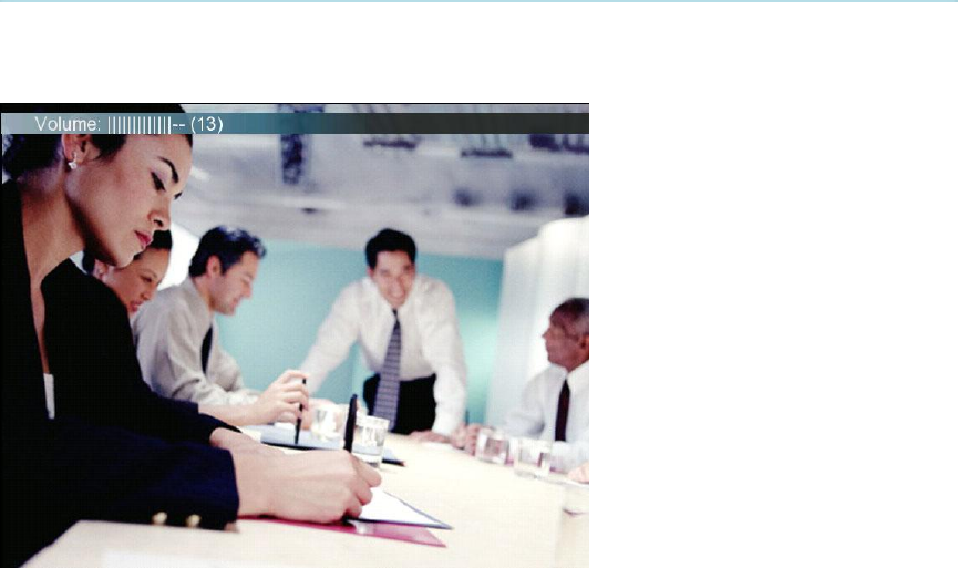
3.2.5 Volume + and -
Press the Volume key to adjust the volume level of the codec only (not the monitor). An on-
screen indicator will show the current level.

TANDBERG 3000 MXP
28
3.2.6 Number and Letter keys
Pressing a number key when outside a call will bring up the call menu. When in a call, the
number keys are used for Camera Presets. Press a number and go to the corresponding Camera
Preset (see Camera Presets). However, when accessing an input field where numbers are
required, the system automatically goes to number mode and numbers can be dialed with the
number keys as usual.
When accessing an input field where letters are required, the system automatically goes to letter
mode. Writing letters works like on a mobile phone. Press the key that corresponds to your
desired letter. Press the key as many times as needed to get the right letter. Change to lower or
back to upper case letters with the a/A key, and space with the 0 _ key.
To write numbers in a text input field, press the button through all the letters. Press once more
and the number will appear.
Example: How do I write "System 123" in the System Name input field (in General in
Administrator Settings)?
Press the 7-key four times to get an "S".
Press the #-key once to switch between upper case and lower case letters.
Press the 9-key three times to get a "y".
Press the 7-key four times to get an "s".
Press the 8-key once to get a "t".
Press the 3-key twice to get an "e".
Press the 6-key once to get an "m".
Press the 0-key once to get space.
Press the 1-key three times to get a "1".
Press the 2-key four times to get a "2".
Press the 3-key four times to get a "3".
General Use
29
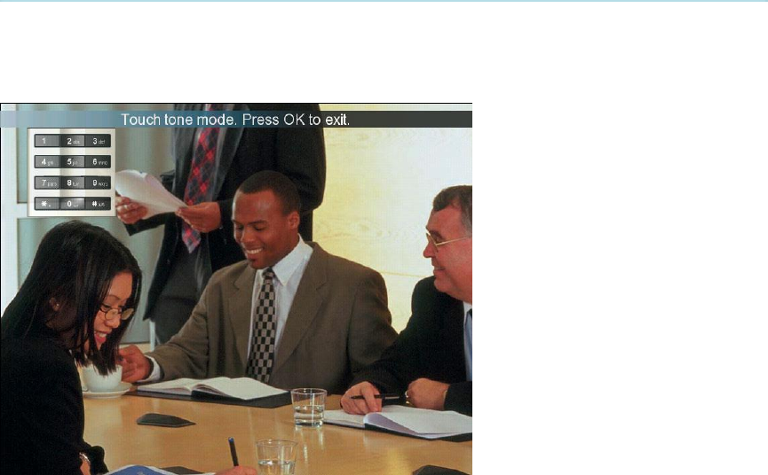
3.2.7 Touch Tones
To activate dialing touch tones during a call, press the Touch tones button. Otherwise the number
keys will activate the corresponding camera presets. An indicator will let you know that Touch
tones are enabled. Finish with OK to exit Touch tone mode.
TANDBERG 3000 MXP
30
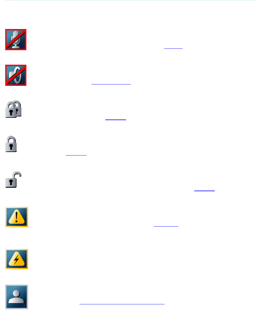
3.3 On-screen Indicators
The system has a number of icons signaling different settings:
Microphone Off
This indicator is shown when the microphone is turned off. Press the Mic off
button again to turn the microphone back on, see Mic Off for details.
Volume Off
This indicator is shown when the volume is turned off. Press Volume + to turn the
volume back on, see Volume + and - for details.
Secure Conference, AES
This double padlock indicator is shown when AES encryption (Secure
Conference) is active, see Security for details.
Secure Conference, DES
This padlock indicator is shown when DES encryption (Secure Conference) is
active, see Security for details.
Not Secure Conference
This open padlock indicator is shown during the initialization phase for AES or
DES encryption. During this period the call is not secure, see Security for details.
Warning
This indicates that the system has detected a warning. Select the icon and press
OK to see details on the warning. Please see Warnings for a list of possible
warnings.
Bad Network
This indicator appears if the system detects network anomalies like packet loss,
jitter etc., during a call. Open the menu by pressing the OK/Menu button and
select the warnings icon too see details.
Floor
This indicator is shown when you are displayed in full screen in a multipoint
conference, see Request Floor and Release Floor for details.

General Use
31
Telephone
This indicates that there is a telephone participant in the conference. The
displayed number indicates how many telephone participants there are in the
conference.
TANDBERG 3000 MXP
32
3.4 Using the Menu
Main menu outside a call and in a call.
Press the Menu button on the remote control to display the menu. The menu contains all
functions needed in order to control the system.

General Use
33
The menu contains the following items:
Make a Call/Add Another Call
Standby/End Call
Camera Control
Presentation
Conference Services
Control Panel
Close
See Menu Structure for a full overview of the menu.
The functions of the menu are displayed as icons. The currently selected icon is marked by an
orange square, and the name of the corresponding function is displayed on the line above, see
the figure above.
Press the OK button to activate the currently selected function.
The menu automatically times out after 15 seconds if not used, see Menu timeout. Press the
Menu button to bring it back. It is also possible to hide the menu manually by pressing the Cancel
button on the remote control or select the Close icon in the menu.
* Systems with no Camera Control icon available may have a Far End Control icon present when in a call and Far End
Control is possible.
TANDBERG 3000 MXP
34
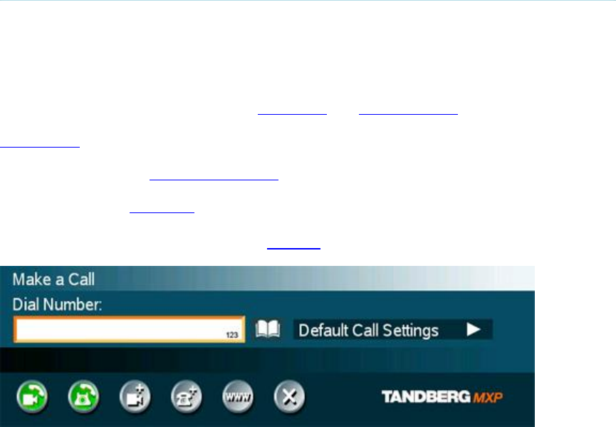
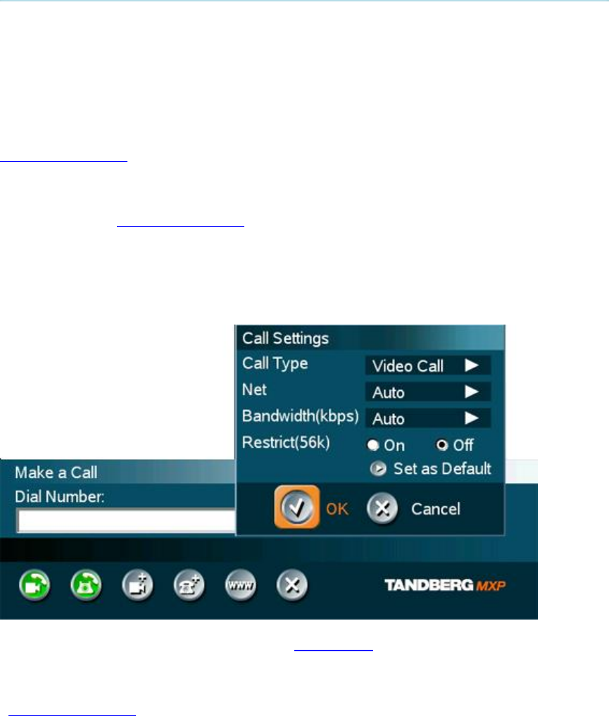
3.5 Make a Call
Display the call menu by either:
1. Select Make a Call from the menu, or
2. Press the green Call button on the remote control
The TANDBERG system can make both Video calls and Telephone calls.
Call Settings specifies the quality of the call. It is possible to alter the default call settings for the
current call if required. The Default Call Settings are defined in Control Panel - Administrator
Settings - Call Quality - Default Call Settings.
It is possible to start Streaming from this menu.
For setting up a MultiSite conference, see Add Call for more details.

General Use
35
3.5.1 Place Video Call
In the Make a Call menu enter the Dial Number either:
1. Manually, or
2. Select the book symbol in order to display the Phone Book and select a conference
participant.
When dialing manually, toggle between ABC/abc by pressing the # button on the remote control
and between abc/123 by holding the # button for one second. Use a star as separator in IP
addresses. If a system is registered on a gatekeeper or border controller with DNS support, there
are several ways to call into the system:
<IP address>
<E.164>
<H.323 ID>
<H.323 ID>@<domain>
<E.164>@<domain>
See H.323 Settings for details.
Place the call by either:
1. Press OK on the remote control so that the Place Video Call icon is selected, and press
OK once again, or
2. Use the arrow button on the remote control to select the Place Video Call icon and press
OK, or
3. Press the green call button on the remote control.
Note that the call will be set up as a telephone call if the Call Type in Call Settings is set to
Telephone Call. See Default Call Settings for more details.
TANDBERG 3000 MXP
36
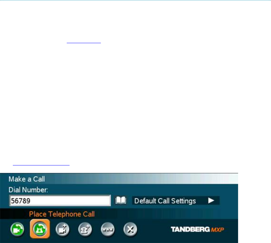
3.5.2 Place Telephone Call
In the Make a Call menu enter the Dial Number either:
1. Manually, or
2. Select the book symbol in order to display the Phone Book and select a conference
participant, see Phone Book for details.
When entering a Dial Number manually, toggle between abc/123 by pressing the # button on the
remote control for one second. Use a star as separator in IP addresses.
Place the call by either:
1. Press OK on the remote control, select the Place Telephone Call icon and press OK once
again, or
2. Use the arrow button on the remote control to select the Place Telephone Call icon and
press OK.
When dialing a telephone number and pressing the green Call button on the remote control, the
system will in most cases automatically interpret the number as a telephone number and not a
video number. The interpretation can sometimes take a little while and it is faster to use the Place
Telephone Call button in the menu.
See Default Call Settings for more details.

General Use
37
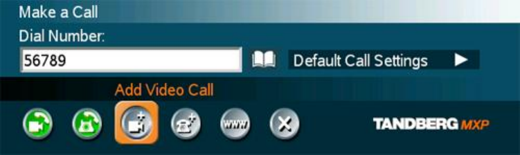
3.5.3 Add Call
(Optional feature)
Conference systems with built-in MultiSite can handle up to 4 video calls and 3 telephone calls
simultaneously.
It is possible to both set up a conference with many participants and also add participants during
a conference.
Set up a conference with two or more participants
In the Make a Call menu enter the Dial Number either:
1. Manually, or
2. Select the book symbol in order to display the Phone Book and select a conference
participant, see Phone Book for details. It is also possible to select a predefined MultiSite
entry, see New MultiSite Contact.
3. Press OK on the remote control.
Add another participant to the conference by either:
1. Select the Add Video Call icon if the next participant is using a video system, and press
OK, or
2. Select the Add Telephone Call icon if the next participant is using a telephone system,
and press OK.
A new entry is now displayed in the call list. Enter the number as described above.
It is also possible to set up a list of all the wanted conference participants by selecting the Add
Video Calls and Add Telephone Calls the desired number of times, and enter their numbers
afterwards.
Place a MultiSite call:
1. If the call is a mixed conference with both video and telephone participants, select the
Place Video Call icon, or
2. If the call is a conference with telephone participants only, select the Place Telephone
Call icon.
Add participant(s) during a conference
Display the call menu during a call by either:
1. Select Make a Call from the menu, or
2. Press the green Call button on the remote control
Enter the new participants in the same way as described above.
TANDBERG 3000 MXP
38
General Use
39
3.5.4 Call Settings
The Call Settings specifies the quality of the call. Each call will be set up with the Default Call
Settings if the settings are not altered. In this case the field is labeled Default Call Settings. If the
settings for some reason are altered for the current participant in the current call, the name of the
field will be changed to reflect this.
Usually it is not necessary for the user to alter the settings.
The Default Call Settings are defined in Control Panel - Administrator Settings - Call Quality -
Default Call Settings.
When setting up a call in the Make a Call menu:
1. Select the Default Call Settings field for the participant and press the OK button on the
remote control.
2. Make desired changes to Call Type, Network, Bandwidth and Restrict (56k). If this is to
be the new default call settings, select Set as Default in the menu.
3. Select the OK icon and press the OK button on the remote control. The name of the Call
Settings field will reflect the changes made.
It is possible to make the changes made to the Call Settings default by selecting Set as Default
and OK. These settings will now be the default settings for all future manually dialed calls.
These settings are also available in the menu Control Panel - Administrator Settings - Call Quality
- Default Call Settings.

TANDBERG 3000 MXP
40
3.5.5 Streaming
Streaming lets you broadcast your meeting to participants on he web. The web participants can
listen to the meeting, see snapshots, but not participate themselves. Snapshots of current stream
(if MultiSite), selfview, far end and DuoVideo streams are accessible via http. See Appendix 6 for
descriptions of the possible snapshot files.
How to use Streaming:
1. Choose Streaming from the Call Menu to open the Streaming menu.
2. Press Start Streaming from the menu line. An indicator will appear on the screen when
streaming is activated.
3. Press Stop Streaming to end streaming. Streaming will also end when you disconnect the
call.
4. Press Streaming Settings if you want to change streaming settings (see Streaming
Settings below)
How to view streaming from a PC:
1. After streaming is started, an easy way to view the streamed audio/video is to start your
Web browser and enter the IP-address of the streaming system.
2. After the Web page of the system is shown, click on Streaming. Alternatively, enter
http://<codec/ip-address>/showstream.ssi
Streaming Settings
Address
Address is defined as the IP-address of a streaming client, streaming
server or a multicast address. Giving an address in the range 224.0.0.1-
239.255.255.255 will broadcast the stream to any host that has joined
the specified multicast group. Specifying normal broadcast address
255.255.255.255 will broadcast to any members on the LAN.
Address Port
If several codec’s are streaming to the same IP-address, different ports
have to be used in order for the client to know which stream to receive.
If the first codec streams on port 2240 and the second codec on port
2250, the client has to specify which port to listen to. Video is
transmitted on the specified port; audio is transmitted on the port
number 4 greater than the specified video port, in this case 2244 and
2254.
TTL/Router
Hops
This is used for streaming data to limit how many routers the data
should pass before it is rejected. If TTL is set to 2, data will not traverse
more than 2 router hops.

General Use
41
Streaming
Source*
Auto: Enables streaming of both local and far end video.
Selection of which site to be streamed is done using voice
switching (the site that speaks is streamed).
Local: Only the local video will be streamed.
Remote: Only the far end video will be streamed.
Local and far end audio is always streamed.
Allow Remote
Start
On: Streaming can be started from external user interfaces like
the Web-browser or Telnet session.
Off: Streaming can only be started from the Video Conferencing
System User Interface using the remote control, or by using the
Data port. This will prevent activation of streaming using Web
browser or Telnet sessions. See also Password section below
Announcements
On: The codec will send announcement packets to the network
that it is streaming. This enables a streaming client (e.g. a PC)
to connect to the codec’s streaming session. Used by Cisco
IP/TV.
Off: No announcement packets will be transmitted.
Video Rate
Defines the Video streaming rate from the system. Range is 16 kbps -
320 kbps. In addition, audio (G.711) streaming rate is 64 kbps, providing
a maximum streaming rate of 384 kbps.
Streaming
Password
Set password so that only participants entering correct password will be
able to view the streaming session. Entering a password will prevent
unauthorized people from accessing the streaming session.
*The streaming source setting is not available when streaming only is supported outside a call.
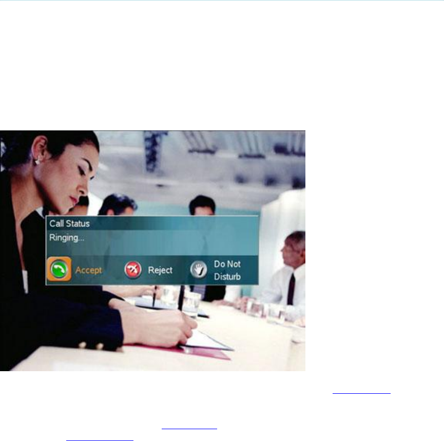
TANDBERG 3000 MXP
42
3.6 Answer an incoming call
How to answer an incoming call:
To accept an incoming call, press the OK button or the green Call button on the remote
control.
How to reject an incoming call:
To reject an incoming call, select the Reject icon and press the OK button, or press the
End Call button on the remote control.
Incoming calls will connect automatically if Auto Answer is set to On, see Auto Answer for details.
When idle, the system will accept all incoming calls as long as Incoming MCU Calls and Incoming
Telephone Calls are set to On, see Permissions for details. Also, Do Not Disturb must not be
activated, see Do Not Disturb for more details.
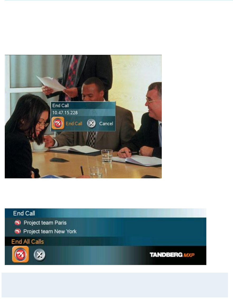
General Use
43
3.7 End Call
How to end a call:
Press the red End Call button on the remote control, or
Press the Menu button on the remote control to display the menu and select End Call.
When the End Call dialog box is displayed either:
Press the red End Call button on the remote control again, or
Press the OK button to confirm that the call is to be ended.
How to end a MultiSite call:
In the list of participants:
Note that switching off the monitor(s), using the power button on the monitor, will not end a
call. Some systems come with monitors that are not possible to switch off.

TANDBERG 3000 MXP
44
3.8 Standby
The system will automatically go to Standby mode when it is not in use. In standby mode, the
screen(s) are black. It is however still possible to receive incoming calls.
How to enter standby mode manually:
Select Standby from the menu and select Standby Now, or
Press the End Call button on the remote control twice.
How to exit standby mode:
When the system is in standby, pick up the remote control, or press any of its keys to
activate the system again.
The standby mode of the system should be enabled if the system is to be left idle.
Note! Standby is not activated by switching off the power to the monitor(s) (some systems
come with monitors that are not possible to switch off.).
If the system is set for Use screen as Local PC monitor, see Screen Settings, the Standby
mode will be disabled when the codec detects a video signal from the PC. If the PC video
signal is not detected, the standby mode will be re-enabled.
It is possible to postpone the system from entering standby mode for 1 hour or 3 hours, see Delay
Standby for 1 hour and Delay Standby for 3 hours.

General Use
45
3.8.1 Delay Standby for 1 hour
Delay Standby for 1 hour postpones the system from entering standby mode for 1 hour.
This function is useful when using the monitors for a local presentation to prevent the system
from automatically blanking the monitors.
It is also possible to postpone the system from entering standby mode for 3 hours, see Delay
Standby for 3 hours.

TANDBERG 3000 MXP
46
3.8.2 Delay Standby for 3 hours
Delay Standby for 3 hours postpones the automatic standby mode for 3 hours.
This function is useful when using the monitors for a local presentation to prevent the system
from automatically blanking the monitors.
It is also possible to postpone the system from entering standby mode for 1 hour, see Delay
Standby for 1 hour.
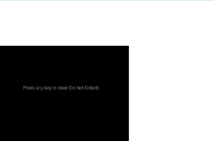
General Use
47
3.8.3 Do Not Disturb
To prevent the system from accepting any incoming calls, activete the Do Not Disturb function.
The caller will hear a busy tone when calling the system. The monitor will be black when Do Not
Disturb is active, see figure below. This is useful when using the display for a presentation as
a local PC monitor and you do not wish any incoming calls during the presentation.
End Do Not Disturb by pressing any key on the remote control.
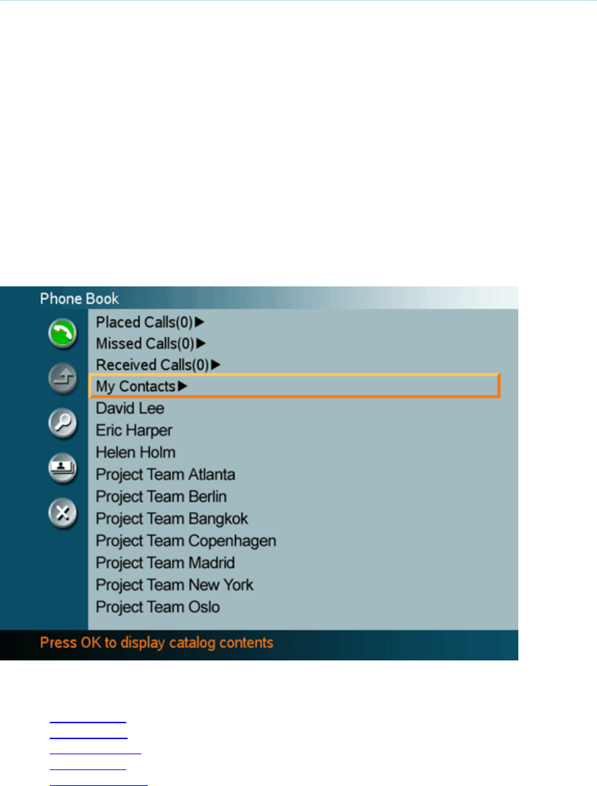
TANDBERG 3000 MXP
48
3.9 Phone Book
The Phone Book is available via the Phone Book button on the remote control or from the Make a
Call menu.
Using the Phone Book is time saving and prevents the user from inadvertently calling the wrong
number. The contacts are sorted alphabetically. The contact names are displayed in the list and
the telephone or video numbers, bandwidth and net profiles of the selected contact are displayed
at the bottom line.
Navigate up and down in the Phone Book with the arrow keys on the remote control. Use the
letter keys to search through the contacts beginning with the typed letter.
The functions in the Phone Book are available when pressing the left arrow key on the remote
control, and then the up and down arrow keys. Note that the last selected contact will be marked.
When selecting Phone Book the phone book opens showing the folders Placed Calls, Missed
Calls, Received Calls and My Contacts. Global Contacts are listed below these folders.
The following information is available from the Phone Book:
Placed Calls
Missed Calls
Received Calls
My Contacts
Global Contacts

General Use
49
3.9.1 Call Log
The Call Log lists Placed Calls, Missed Calls and Received Calls. That allows the user to see
which calls that are made in the past. The lists contain a maximum of 30 numbers and the
numbers are stored in these lists until the system is restarted. If the contacts listed are available
in the phone book, the names will be displayed instead of the numbers.
Placed Calls lists all outgoing calls, Missed Calls lists the calls that are not accepted and
Received Calls lists all incoming calls. The calls in the lists are marked with these icons:
outgoing calls
incoming calls
missed calls
The following buttons are available from these folders :
Call Now
Copy to My Contacts
Delete
Delete All
Cancel
How to make a call using the call lists:
1. Select a number from the list.
2. Press the green Call button on the remote control, or press the left arrow key to select the
Call Now icon, followed by OK. The call will be set up as a video call or a telephone call
depending on the selected contact. Alternatively, press the OK button when the contact is
selected. The Make a Call menu will then be displayed with the name of the contact in
the Dial Number field, and the Call Settings field will reflect the call settings for this
contact. It is possible to alter the call settings before placing the call. The call will be set
up as a video call or a telephone call as described in Make a Call.
3. Wait for the call to connect.
How to delete numbers in the call lists do one of the following:
Choose the Delete button to delete a selected contact from the call list.
Choose the Delete All button to delete all contacts listed in the call list.
Note that you will not delete contacts from the Phone Book if you delete them from the call lists.
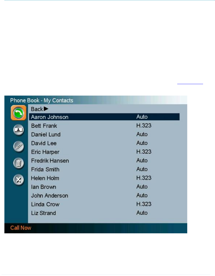
TANDBERG 3000 MXP
50
3.9.2 My Contacts
My Contacts are the locally stored contacts on the system. This means that it is possible to add
new contacts and edit or delete existing contacts. My Contacts can store up to 200 contacts.
How to make a call using My Contacts:
1. Find the desired contact using the arrow keys or searching on the first letter with the letter
keys.
2. Press the green Call button on the remote control, or press the left arrow key to select the
Call Now icon, followed by OK. The call will be set up as a video call or a telephone call
depending on the settings made when storing the contact. Alternatively, press the OK
button when the contact is selected. The Make a Call menu will then be displayed with
the name of the contact in the Dial Number field, and the Call Settings field will reflect the
call settings for this contact. It is possible to alter the call settings before placing the call.
The call will be set up as a video call or a telephone call as described in Make a Call.
3. Wait for the call to connect.
Note that the telephone or video number and profile of the selected contact are displayed on
the bottom line.

General Use
51
The following functions are available from My Contacts:
Call Now
New Contact
New MultiSite Contact
Edit Contact
Delete Contact
Close
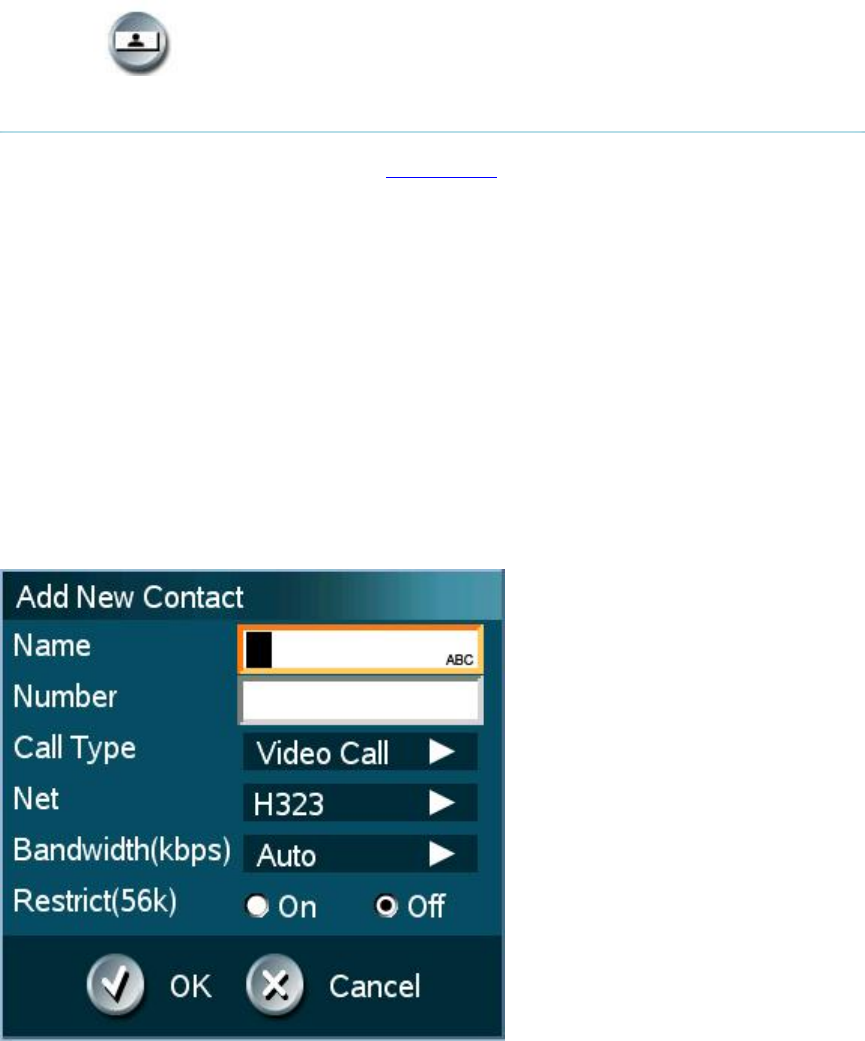
TANDBERG 3000 MXP
52
3.9.2.1 Add New Contact
The New Contact function is available from My Contacts.
Add a new contact to My Contacts by:
1. Select the New Contacts button to open the New Contacts dialog box.
2. Enter Name by using the letter keys on the remote control. Input will automatically be
interpreted as letters. Toggle between capital letters and small letters by pressing the #
button on the remote control. The maximum name length is 30 characters. For numbers,
press the # button for one second.
3. Enter Number by using the number keys on the remote control. Input will automatically be
interpreted as numbers. The maximum number length is 60 numbers. Use a star as
separator in IP addresses. For letters, press the # button for one second.
4. Alter the default setting of Call Type if necessary.
5. Alter the default setting of Network if necessary.
6. Alter the default setting of Bandwidth if necessary. For bandwidth 2x64 kbps or 2x56
kbps, two numbers are required, see Default Call Settings for more details.
7. Alter the default setting of Restrict (56k) if necessary.
8. Press OK to save.

General Use
53
3.9.2.2 New MultiSite Contact
(Optional feature*)
The New MultiSite Contact function is available from My Contacts.
It is possible to pre-define the participants of a conference meeting as a MultiSite Contact. All
participants in the MultiSite Contact will then be connected automatically instead of having to call
the participants one by one.
My Contacts can hold up to 50 MultiSites Contacts. The MultiSite Contacts consist of participants
that are already stored in My Contacts.
It is possible to have up to a total of 4 video participants and 3 telephone participants in a
meeting.
How to define a New MultiSite Contact:
1. Open the Phone Book via the Phone Book button on the remote control or in the Make a
Call menu.
2. Select the New MultiSite Contact icon. The New MultiSite Contact dialogue box is
displayed.
3. Enter a name of the MultiSite Contact, and press OK on the remote control.
4. Select Add Participant. The contents of the Local Phone Book is displayed. Find the
desired contact and press the OK button on the remote control. Repeat until all the
desired participants are selected.
5. Press OK to save the MultiSite Contact.
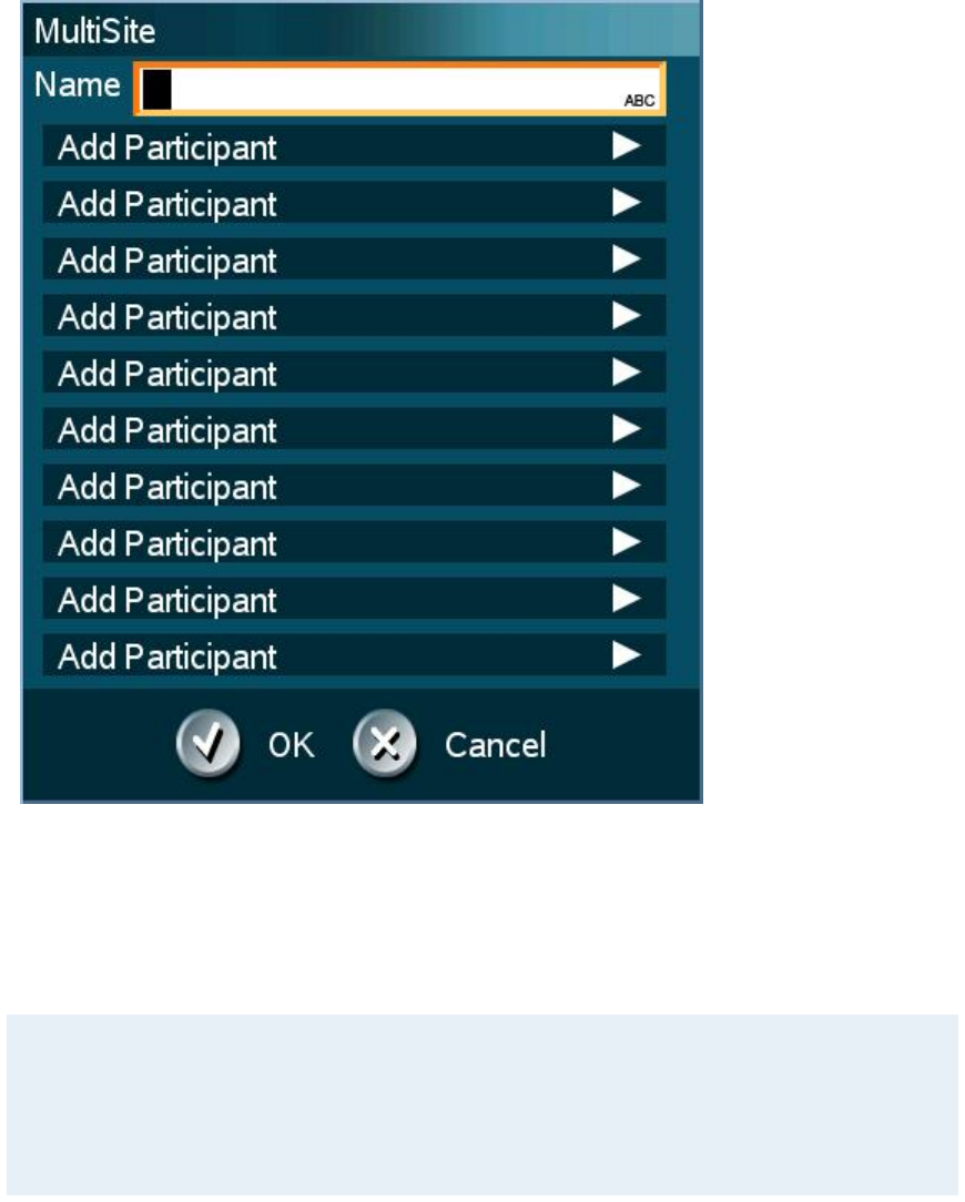
TANDBERG 3000 MXP
54
Bandwidth for a MultiSite Contact call
When calling a MultiSite Contact, the system will try to call the participants with their specified
bandwidths. If the total bandwidth exceeds the system's maximum bandwidth, the system will
downspeed and distribute the available bandwidth equally among all the participants.
Example: In a MultiSite Contact there is one participant with bandwidth 256kbps and one
participant with bandwidth 384kbps. 512kbps is the maximum bandwidth of the system.
The two participants' bandwidth exceeds the maximum bandwidth. The system will then
downspeed so that each participant connects with equal bandwidth, i.e. 512kbps/2 = 256kbps.
* The MultiSIte option is not available on the TANDBERG 550 MXP, TANDBERG 770 MXP and TANDBERG 1000 MXP
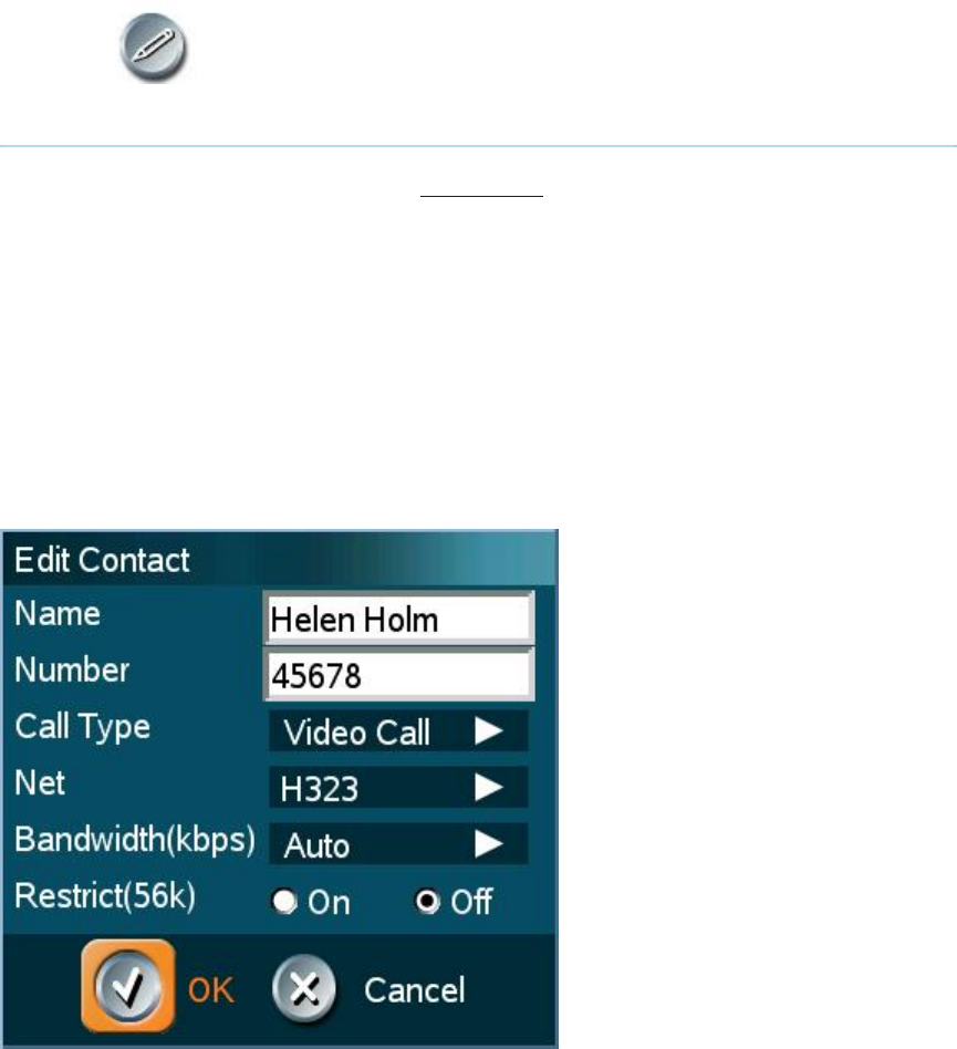
General Use
55
3.9.2.3 Edit Contact
The Edit Contact function is available from My Contacts.
How to edit a contact in the Local Phone Book:
1. Select the contact that is to be edited.
2. Press the left arrow on the remote control, followed by the down arrow until the Edit
Contact icon is selected.
3. The current settings for this contact is displayed in a dialogue box. Alter the wanted
settings.
4. Press OK to save.
If the altered contact is part of a MultiSite Contact*, the contact will be updated in the MultiSite
Contact automatically.
* The MultiSite option is not available on all systems.
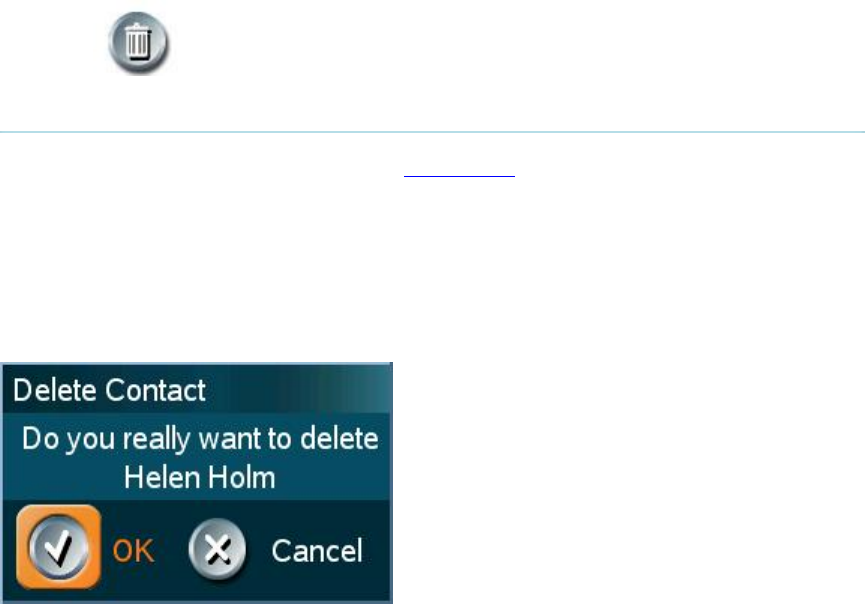
TANDBERG 3000 MXP
56
3.9.2.4 Delete Contact
The Delete Contact function is available from My Contacts.
How to delete a contact:
1. Select the contact that is to be deleted.
2. Press the left arrow on the remote control, followed by the down arrow until the Delete
Contact icon is selected. The Delete Contact dialogue box is displayed.
3. Confirm by pressing the OK button again.

General Use
57
3.9.3 Global Contacts
When selecting Phone Book the phone book opens showing the Global Contacts* or the
Corporate Directory** below the folders Placed Calls, Missed Calls, Received Calls and My
Contacts.
These contacts cannot be changed locally by the system, only from the management system. If
there is a need to modify the number or any settings of a contact before making a call, select the
contact and press OK on the remote control. The Make a Call menu is displayed and the settings
can be altered before placing the call. The changes are not saved.
How to make a call using Global Contacts:
1. Find the desired contact using the arrow keys or searching on the first letter with the letter
keys or use the search function described in Search.
2. Press the green Call button on the remote control, or press the left arrow key to select the
Call Now icon, followed by OK. The call will be set up as a video call or a telephone call
depending on the settings made when storing the contact. Alternatively, press the OK
button when the contact is selected. The Make a Call menu will then be displayed with
the name of the contact in the Dial Number field, and the Call Settings field will reflect the
call settings for this contact. It is possible to alter the call settings before placing the call.
The call will be set up as a video call or a telephone call as described in Make a Call.
3. Wait for the call to connect.
From Global Contacts the following functions are available:
Call Now
Up one Level
Search
Copy to My Contacts
Close
* The Global Contacts are stored locally on the ftp-server of the system. This will include the first 400 entries of the
Corporate Directory, and will not contain any folders. This directory is hidden from the user as long as the system is able
to fetch the Corporate Directory, otherwise the Global Contacts will be displayed.
** The Corporate Directory is available if the system is connected to an external management system like the TANDBERG
Management Suite (TMS) and if it is enabled in Phone Book Settings.

TANDBERG 3000 MXP
58
3.9.3.1 Up one Level
Global Contacts can be arranged in a tree structure with several sub folders. Use the Up one
Level button to navigate up in the tree structure.
When a search in the Global Phone Book is made, by using the Search function, only contacts
matching the search text are displayed. Select the Up one Level button to return back to the
alphabetical list.

General Use
59
3.9.3.2 Search
The phone book can contain an unlimited amount of global contacts. Using search makes it
easier to find the wanted contact.
How to search in the Global Phone Book:
1. Select the Search icon.
2. Enter search text in the dialogue box that appears and press the OK button on the
remote control. The system will list all entries that contain the entered letter combination.
3. It is also possible to search on first letter in the Phone Book with the letter keys on the
remote control.

TANDBERG 3000 MXP
60
3.9.3.3 Copy Contact to My Contacts
The Copy Contact to My Contacts function is available from the Placed Calls, Missed Calls,
Received Calls and Global Contacts folders, see Phone Book for details.
It may be wise to copy contacts that are often used to My Contacts. Note that the local copy will
not be updated if the Global Contacts are updated from the management system.
How to copy a contact from the Global Phone Book to the Local Phone Book:
1. Select the contact to be copied to My Contacts.
2. Press the left arrow on the remote control, followed by the down arrow until the Copy
Contact to My Contacts icon is selected.
A message box telling that the operation was successful will be displayed.

General Use
61
3.10 Camera Control
There are several ways to control the camera:
Control the camera directly with the arrow keys when the menu is closed or use the Move
Camera function in the menu to control both the near end and far end camera, see Move
Camera and Far End Control for details.
Use the zoom button on the remote control will zoom the picture in (+) and out (-).
Use Camera Presets, see Camera Presets for details.
Adjust focus, brightness and whitebalance, see Picture Control for details.
Use Automatic Camera Tracking, see Camera Tracking for details.
Use the TANDBERG Tracker, see separate instructions included with the TANDBERG
Tracker.

TANDBERG 3000 MXP
62
3.10.1 Move Camera
It is possible to move the camera with the remote control or via the menu.
Moving the camera directly with the remote control
When the menu is hidden, the arrow keys will work on the camera. If the menu is displayed, press
the Cancel button on the remote control to hide it. Use the left and right arrow keys to pan the
camera, and the up and down arrow keys to tilt the camera. Use zoom + and – to zoom in and
out.
Moving the Camera via the menu:
1. Select the Camera Control icon from the menu.
2. Select the Move Camera button in the Camera Control menu.
3. Use the arrow keys on the remote control to pan and tilt the camera.
4. Press OK when done.

General Use
63
3.10.2 Far End Control
Far End Control allows you to control your conference partner’s camera. An example of when this
feature could be especially helpful is if it is not possible to see what a participant at the far end is
writing on their white board. Use Far End Control to move the far end camera and zoom closer on
the white board. Far End Camera Control is useful if e.g. it is not possible to see what a
participant at the far end is writing on their white board. Use Far End Control to move the far end
camera and zoom closer on the white board. Use the left and right arrow keys to pan the camera,
and the up and down arrow keys to tilt the camera. Use zoom + and – to zoom in and out.
You can also control your conference partner’s video sources and presets and even request a
snapshot from the far end side. Enabling Far End Control will put the system in Far End mode
and camera control, camera preset, presentation, and snapshot will work on the far end camera.
Far End Control only works when you are in a call and if the far end side supports H.281 (Far End
Camera Control). You can prevent others from controlling your system by setting Allow Far End
Camera Control to Off in Control Panel - Administrator Setting - General - Permissions, see
Permissions for details.
How to use Far End control:
1. Select the Camera Control icon in the menu.
2. Select the Far End Control icon. When far end camera control is selected an indicator will
appear and it is possible to control the far end camera, camera preset, presentation and
snapshot for the far end.
3. Deselect the Far End Control button to deactivate far end control mode. This may also be
done by pressing the Cancel or the OK button.
Far End Camera Presets
Far End Camera Presets work just like your own camera presets. When Far End is on, use the
number keys to activate far end camera presets. You are however not allowed to save far end
camera presets.
Far End Presentation
Pressing the Presentation key or choosing a presentation from the presentation menu while Far
End is on, will result in opening a far end presentation. Be aware of that the far end video sources
may not correspond with the buttons in the presentation menu. If you press Document Camera,
the far end side might have configured another video source on this input.
Request snapshot from the Far End
You can request a snapshot from the far end side. Put the system in Far End mode and press
Snapshot on the remote control to take a snapshot of the current far end video (current is default
snapshot source).

TANDBERG 3000 MXP
64
3.10.3 Camera Presets
Use camera presets to easily vary between predefined near end camera angles. This is useful
when pictures from many different camera angles have to be sent to the far end. E.g. in a
meeting there is a white board, a PC and a small meeting table. Use camera presets to move
between these camera perspectives in order to present the correct information to the participants
at the far end without having to move the camera manually every time. A preset is deactivated
when the camera is moved manually with the arrow keys.
Presets are available from the menu. When you are in a call you can also activate presets directly
from the remote control. You can save up to 15 presets. Each camera preset is able to store
camera angle, video source and audio source selection.
How to use preset directly from the remote control:
When you are in a call you can activate presets with just one press on the number keys on
remote control. The number keys will however not work as presets when you are in an input field,
in order to write numbers or letters.
1. Press a number on the remote control. The camera will move to the corresponding angle,
or video source, stored on that number.
How to use presets via the menu:
1. Select Camera Control - Display Presets in the menu.
2. Select the wanted preset with the arrow keys on the remote control and
press OK.
How to save a new preset directly from the remote control:
1. Move the camera to the desired position or select the desired video source that you
would like to store as a preset.
2. Press a number on the remote control for 1 second to save the preset. It is possible to
store one camera preset on each of the number keys, 0-9, when storing camera presets
from the remote control. (Camera preset 10 is stored on the 0-key).
3. The new camera preset will overwrite any existing camera preset on that number.
How to save a new Preset via the menu:
1. Move the camera to the desired position or select the desired video
source that you would like to store as a preset.
2. Select Camera Control - Save New Camera Preset in the menu.
3. Enter a number between 0 and 14 and press OK.
4. Type a name for the preset to make it easier to separate the different
presets.
5. Press Save. The new Camera Preset will overwrite any existing camera
preset on that number.
General Use
65
3.10.4 TANDBERG Tracker
How to save presets for the TANDBERG Tracker:
1. Select which camera preset is to be used on the TANDBERG Tracker.
2. Move the camera to the desired position to store on the tracker.
3. Select Move Camera - Save New Preset in the menu.
4. All camera presets are accessible from the TANDBERG Tracker.
For more information, see separate instructions included with the TANDBERG Tracker.

TANDBERG 3000 MXP
66
3.10.5 Picture Control
Focus, Brightness and White balance are set for auto focus, auto brightness and auto white
balance by default. If you need to set focus, brightness and white balance manually, go to Picture
Control in the Camera Control menu.
Focus
Auto Auto focus continuously updates the focus throughout the call. When moving
the camera, the system will use auto focus for 5 seconds to set the right focus
of the new camera position. After 5 seconds auto focus is turned off to prevent
continuous focus adjustments of the camera.
Temporary
When Temporary is selected, the slide bar is enabled. Use the arrow keys to
adjust the focus. The temporary focus will last until you move the camera again
and auto focus will take effect.
Camera Brightness
Auto
Auto brightness continuously updates the brightness of the camera picture.
Manual When Manual is selected, the slide bar is enabled. Use the arrow keys to manually
adjust the camera brightness. If brightness is set manually, the system will keep
this brightness level also when the camera is moved.
White balance
Auto Auto white balance continuously updates the white balance.
Manual When Manual is selected, the “Set White balance” field is enabled. To update the
white balance manually, select Manual. A white object should be held in front of
the camera a few seconds before and after pressing “Set White balance”. If white
balance is set manually, the system will keep this white balance also when the
camera is moved.

General Use
67
3.10.6 Camera Tracking
Through Camera Tracking and the use of two or three microphones, the camera can
automatically position itself on the current speaker. Before using camera tracking, the camera
positions used must be stored at Preset 7 (Mic1) and Preset 8 (Mic2).
How to use Camera Tracking:
1. Select the Camera Control icon in the main menu.
2. Enable Camera Tracking by choosing Camera Tracking. An indicator will appear on the
screen.
3. End Camera Tracking by deselecting the Camera Tracking button. Camera Tracking will
also end if you activate a camera preset or move the camera manually with the arrow
keys.
Example: You have placed Microphone 1 on the table. Where should you position the camera
for Preset 7?
The camera position stored at Preset 7 must be related to Microphone 1. Therefore all
participants who are located closest to Mic1 should be included in the Preset 7 camera
position etc. When camera tracking is activated and a person close to Mic1 speaks, Preset 7
will be automatically selected.
When activating another video source (for instance document camera), camera tracking will be
temporarily disabled until you re-select Main Camera or a Main Camera preset.
The camera tracking speeds may be altered in the Video Settings menu in Administrator Settings,
see Camera Tracking Mode for further details.
A Voice Detector makes the system more tolerant of noise and ensures the camera not to move
by noise such as paper shuffling, etc.
Note that pressing Mic Off will temporarily disable camera tracking until you turn on the
microphone again.
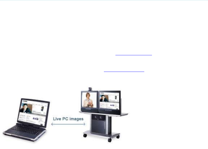
TANDBERG 3000 MXP
68
3.11 Presentation
The Presentation Functionality in the system enables you to show other available video sources
in addition to your Main Camera. This is perfect for meetings where you would like to show a
PowerPoint presentation, for example. You can even use arrow keys up and down on the remote
control to activate Page Up/Down on the PC (this only applies when using VNC).
Use Presentation outside a call to make a local presentation for the people in your own meeting
room. Use Presentation when you are in a call to make a presentation for the far end as well.
The quickest way to show a presentation is to use the Presentation Key on the remote control.
The presentation key shows a predefined video source, PC is the default. It is possible to change
the presentation source in the Presentation menu. Choose Presentation from the main menu if
you want to select a video source manually. The Presentation Menu offers you all the available
video sources supported by your system.

General Use
69
3.11.1 Presentation Key
The quickest way to show a presentation is to use the presentation key on the remote control.
The presentation key is used to start and stop a presentation. The presentation key will display
PC (default*).
When holding the presentation key for 1 second, the presentation menu will be displayed. This
menu allows you to choose other video sources.
The default presentation source can be permanently changed in Presentation Settings.
When using the presentation key, your presentation will be displayed as a Dual Stream, if
possible. If the call does not support a dual video stream, the presentation will display as main
video stream.
How to start and end a Presentation using the Presentation key:
1. Press the Presentation key. The video source that is set as presentation source is
displayed in full screen (PC is default). Remember to connect your PC to the codec in
advance.
2. Press the Presentation key again to end the presentation and go back to main camera.
* If available on your system.
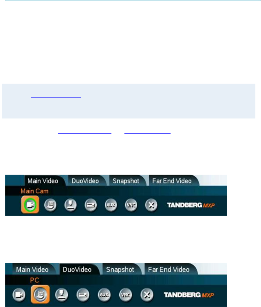
TANDBERG 3000 MXP
70
3.11.2 Presentation Menu
The Presentation menu offers you all available video sources; Main Camera, PC, Document
Camera, VCR, AUX and VNC. All these sources can be used as Main Video Stream or Dual
Video Stream (Duo Video / H.239). Not all systems has all video sources available, see Interfaces
for details.
Outside a call the presentation menu only contains Main Video Sources. In a call, the headers
Dual Video and Snapshot display in addition to Main Video (if the call supports Duo Video
/H.239). Use the up/down keys to change between video sources and headers. Start a Dual
Stream by selecting a Dual Video source. Close the Dual Stream by deselecting the video source
button.
Note that Dual Video Stream may not be available if the option is not installed, not supported
on your system or if already activated. Use the up/down keys to change between video source
and header.
For Snapshots, see Take New Snapshot and Display Snapshot.
How to change your main video source:
1. Choose the Main Video header from the Presentation menu.
2. Choose your desired video source and press OK.
How to show a presentation in addition to your main video (Dual Video Stream):
1. Select the Duo Video header.
2. Choose a dual video source and press OK.
3. Deselect the active video source button to end the presentation.
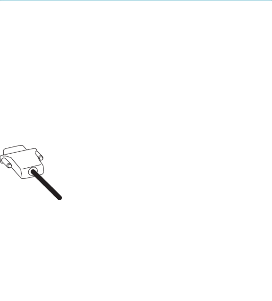
General Use
71
3.11.3 PC Presenter (DVI/XGA Input)
(Optional feature - not available on all systems)
Users often have their presentations on a laptop that is brought into the meeting room.
Remember to connect your PC to the codec before you press the Presentation button. Note that
the image will appear smoother on the system if your presentation is already displaying in full
screen on your PC prior to connecting your PC to the video system.
Plugging a PC into the system is made extremely simple through the PC Presenter, avoiding the
need for any additional hardware such as a projector, PC/Video converter or extra cables.
How to connect a PC to the codec with the DVI/VGA cable:
1. Connect the VGA-DVI cable to the PC Presenter (PC DVI-I in) connector on the codec.
2. Connect the VGA-DVI cable to your PC (VGA Output).
3. If you would like to use audio as part of the presentation, connect the headset jack on
your PC to the audio input on the PC presenter VGA cable.
4. When the PC is connected to the codec, hit the Presentation key to display the PC image
on the system.
If no PC image is displayed on your monitor, make sure that your PC is set to activate your VGA
output. On most laptop PCs you must press a special key combination to switch the PC image
from the PC screen to the video screen.
Note that the DVI/VGA input is compliant with VESA Extended Display Identification Data (EDID)
and will be able to reconfigure the PC’s screen settings if it is currently configured to a VGA
format that the system doesn’t support.
Also note that you can use the DVI input to transmit high resolution images from document
cameras or other sources supporting the HD format 720p.
For details on formats supported on 'DVI-I in', please refer to Interfaces.
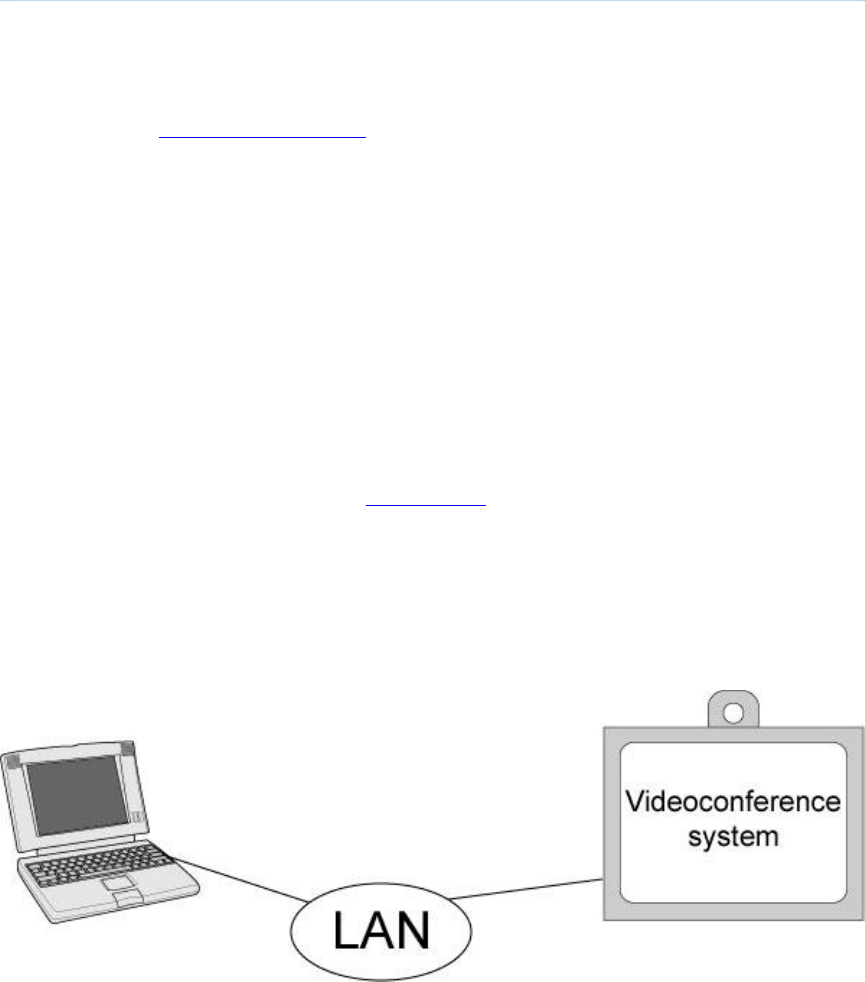
TANDBERG 3000 MXP
72
3.11.4 PC Soft Presenter and VNC
(Optional feature)
PC SoftPresenter is used to display PC images on your system without using a VGA cable (PC
Presenter). The system and your PC must be connected to the same LAN. In addition, VNC
(Virtual Network Computing) server software must be installed on the PC. Free software can be
downloaded from http://www.realvnc.com. Install the software by running the downloaded file.
How to configure the VNC Server software:
1. Select the following to setup VNC; Windows-Start\All Programs\Highlight
RealVNC\Hightlight VNC Server\Show User Properties
2. Select Accept Socket Connections.
3. Select Auto for Display Number. Display Number in the system must then have the value
0.
4. Enter a password in the Password-field. This must correspond with the VNC Settings on
your system.
How to show PC using the PC Soft Presenter and VNC:
1. Start the VNC software on your PC.
2. To use VNC, you must configure VNC Settings. Open VNC Settings in the Presentation
Settings menu in Administrator Settings.
3. Fill in the IP address of your PC, Display Number and Password.
4. Press Save.
5. When you now choose VNC as video source in the Presentation menu, you will see your
PC using VNC. If a PowerPoint presentation is being displayed then you can scroll
through the presentation by pressing the up and down arrows on the remote control. VNC
settings will go back to default when the system goes to standby.

General Use
73
3.11.5 Dual Stream (DuoVideoTF/H.239)
(Optional feature - not available on all systems)
With Dual Stream you have the opportunity to show two different live video streams
simultaneously, main video and one additional source. This is handy when showing a
presentation. You see the live presentation and the live video of the presenter simultaneously.
When you start a presentation, Dual Stream starts automatically if both local and remote system
supports Dual Stream. If one of the systems does not support Dual Stream, no second video
stream will be established and your presentation will be shown as your main video.
Dual Stream is available on all systems with Natural Presenter Package installed. H.239 is the
new ITU standard defining how to send two video sources simultaneously.
Example:
Start a meeting with main camera as video source. Press the presentation key on the remote
control to start a PC presentation.
PC will appear as a Dual Video Stream in addition to main camera. End the Dual Stream
presentation by pressing presentation key again.
In Presentation Settings, you can set Presentation Start to Manual. That means that Dual Stream
will not start automatically.
Example:
Start a meeting with main camera as video source. Press the presentation key on the remote
control to start a PC presentation.
A dialog box appears where you can choose to show PC as Dual Video Stream or not. This is
handy if you not always want to use Dual Stream.
Dual Stream and Bandwidth
Using Dual Stream, the quality automatically downspeeds to the optimal bandwidth. This means
that you need higher quality to allocate enough bandwidth for the two video streams. Dual Stream
borrows bandwidth from main video stream. When Dual Stream is closed, the bandwidth is
returned to the main video.
Note that when selecting the Document Camera or PC, the system will automatically request floor
when connected to a MCU conference as MultiSite host* or connected to an external MCU.
* Not available on all systems.
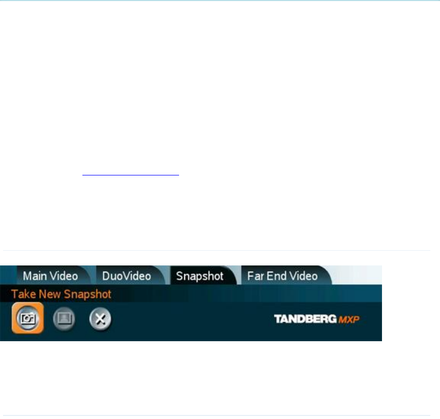
TANDBERG 3000 MXP
74
3.11.6 Take New Snapshot
The system can take a snapshot of your live video. Snapshot is handy when you are in a call with
a system that does not support Dual Stream. Use Snapshot to show a snapshot of your
presentation and continue the meeting with main camera.
How to use snapshot:
You find Take New Snapshot in the Presentation menu.
1. Select the Snapshot header.
2. Select Take New Snapshot and press OK to take a snapshot.
Snapshot is found on the Star key on the remote control.
1. Press Star and you take a snapshot of the current video source (current video is default
snapshot source). You can change the snapshot source in Control Panel - Administrator
Settings - Presentation Settings. Note that snapshot does not work when you are in an
input field in the menu (the star key is then used to write the star sign).
Note that Take New Snapshot is not possible when Dual Video Stream is activated and that
it is only available when you are in a call.
Note that the Snapshot feature uses H.261 Annex D and hence will not work when using
H.264 video compression

General Use
75
3.11.7 Display Snapshot
The system stores the last sent or received Snapshot. The snapshot is deleted automatically after
the call.
How to display snapshots:
1. To view a stored snapshot, first choose the Snapshot header.
2. Select Display Snapshot in the Presentation menu.
3. Press the Display Snapshot button again to deselect it. When disconnecting the call, the
stored snapshot will be erased.
Receiving snapshots:
1. When receiving a snapshot, the snapshot is displayed in full screen.
2. Press OK to exit from the snapshot. The last sent or received snapshot will be stored in
the graphics memory and erased once the call is disconnected.
Note that Display Snapshot is only available when you have a stored snapshot.
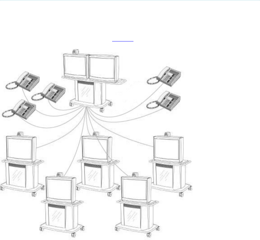
TANDBERG 3000 MXP
76
3.12 Conference Services
A Multipoint Control Unit (MCU) enables several sites to participate in the same conference.
During an MCU conference, the status line will provide information about the conference.
You can make a multipoint conference in different ways. The Conference Services vary
depending on how you make the call, see Add call for details.
Example of MultiSite for high end systems. Note that the illustrations may differ from the actual
product.
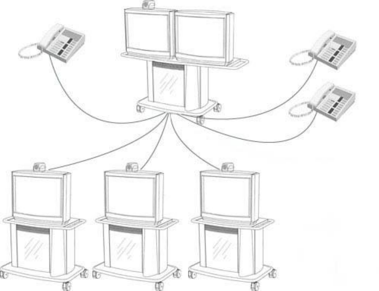
General Use
77
Example of MultiSite for mid- to low end systems. Note that the illustrations may differ from the
actual product.
Using the system’s internal MCU, MultiSiteTF *
Most TANDBERG MXP systems have an optional built-in MCU, which is called MultiSite*. It
supports up to 6 video calls and 5 telephone calls including yourself for high-end systems, and 4
video calls and 3 telephone calls including yourself for the mid- and lower end systems. The
MultiSite supports both Split Screen and Voice Switched mode. With MultiSite, you have the
following services:
Request/Release Floor
Assign Floor To Participant/Release Floor From Participant
Terminal Names
Layout (Auto/4 Split/5+1 Split/Voice Switched)
Using an external MCU that supports Chair Control (H.243)
With an external MCU that supports H.243, you have the following services:
Request/Release Floor
View Participant/End View
Chair Control
If you take Chair control, you get the following services:
Release Chair
Assign Floor To Participant/Release Floor From Participant
Disconnect Participant
Terminate Meeting
TANDBERG 3000 MXP
78
Using an external MCU with limited Chair Control Support you may have the following
services
With an external MCU that does not support H.243, you have the following services:
Request/Release Floor
Terminal Names
* The MultiSIte option is not available on the TANDBERG 550 MXP, TANDBERG 770 MXP and TANDBERG 1000 MXP

General Use
79
3.12.1 Request Floor and Release Floor
When requesting floor, your video will be broadcasted in full screen to all other participants in the
conference. Request Floor is useful when you want to speak or display something in front of all
participants.
Release Floor when you are done and make the floor available for other participants in the
conference. An indicator appears when you have floor and disappears when you release floor,
see floor indicator in On-screen Indicators.
How to use Request and Release Floor:
1. Open the Main Menu by pressing OK.
2. Choose Conference Services and press OK.
3. Choose Request Floor and press OK. A Floor indicator will appear when you have floor.
4. When done, press the same button again, which now means Release Floor. The Floor
indicator disappears.
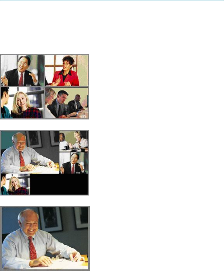
TANDBERG 3000 MXP
80
3.12.2 Conference Layout
(Only supported by TANDBERG MultiSite*)
With a TANDBERG MultiSite you can choose between the layouts: Auto Split, 4 Split, 5+1 Split
and Voice Switched view. Auto Split displays all participants on the screen simultaneously. 4 Split
displays the 4 last speaking Participants including the MultiSite host. 5+1 Split displays the
speaking participant in a big picture and the other participants in small pictures. Voice Switched
mode displays the participant that is speaking in full screen. Switch between these picture modes
using the Conference Layout menu.
Continuous Presence layout 4 split
Advanced Continuous Presence Layout (5+1).
Voice Switched mode
* The MultiSite option is not available on the TANDBERG 550 MXP, TANDBERG 770 MXP and TANDBERG 1000 MXP

General Use
81
3.12.3 Terminal Names
Choose Terminal Names to see a list of the participants of the MultiSite conference. Press Cancel
to go back.

TANDBERG 3000 MXP
82
3.12.4 Chair Control
(Not supported by TANDBERG MCU or MultiSite)
As chairman, you have access to more MultiSite Services. Select Chair Control to assume the
role of chairman of the conference. Select Release Chair to end the role as chairman. A Chair
indicator appears when you have Chair and disappears when chair is released.

General Use
83
3.12.5 Assign Floor and Release Floor from
Participant
Assign Floor allows the chairman to select which of the conference participants are to be
broadcasted to all other participants.

TANDBERG 3000 MXP
84
3.12.6 View Site and End View
(Not supported by TANDBERG MCU or MultiSite)
View Site allows you to view any participant in the conference regardless of who has the floor and
chair. Choose End View to go back to normal.

General Use
85
3.12.7 Disconnect Participant
Disconnect Participant allows the chairman to disconnect any participant in the conference. In a
multipoint call, this is equivalent to disconnecting a participant from the end call menu.

TANDBERG 3000 MXP
86
3.12.8 Terminate Meeting
Terminate Meeting allows the chairman to terminate the conference altogether. In a MultiSite call,
this is equivalent to pressing End All Calls from the end call menu.

General Use
87
3.12.9 More about MultiSite (embedded MCU)
(Optional Feature*)
Calling in to a MultiSite
Any system can be part of a MultiSite conference by calling in to a MultiSite. The dial-in numbers
to the MultiSite depends of the network that is used.
To dial in to the MultiSite on IP:
Dial the IP Number or the IP Address of the system. All sites can dial the same number.
To dial in to the MultiSite on ISDN-PRI:
Dial the ISDN number of the system. All sites can dial the same number.
To dial in to the MultiSite on ISDN-BRI:
The MultiSite has specific numbers for each call that participates in the conference. To
find the dial-in numbers for the MultiSite, choose Information from the main menu and
open System Information from the bottom menu line.
Site 2 must dial MultiSite Number 2.
Site 3 must dial MultiSite Number 3.
Site 4 must dial MultiSite Number 4.
And so forth
Receiving calls to a MultiSite
When the MultiSite receives incoming calls you can accept or reject it. Pressing the green key is
equivalent to pressing Accept. Pressing the red key is equivalent to pressing Reject.
End a MultiSite Call
Ending a MultiSite Call is not very different from ending a normal point-to-point call. Use the red
key on the remote control or End Call from the main menu. The end call menu lists all the calls
that participate in the conference. To end a single call, select the call, press OK or the red key on
the remote control. To end all calls, press the End All Calls button in the menu.
Duo Video in MultiSite calls
In a MultiSite call, the MultiSite can transmit the Duo Video and/or H.239 to the other participants
that support Duo Video and/or H.239. This means that any participant can send Dual Stream and
the MultiSite will transmit it to the other participants. The participants that do not support Duo
Video or H.239 will only receive Main Video or only the dual stream dependent on software
options installed.
Mix ISDN/IP
A conference can consist of any combination of ISDN/IP sites.
* The MultiSite option is not available on the TANDBERG 550 MXP, TANDBERG 770 MXP and TANDBERG 1000 MXP
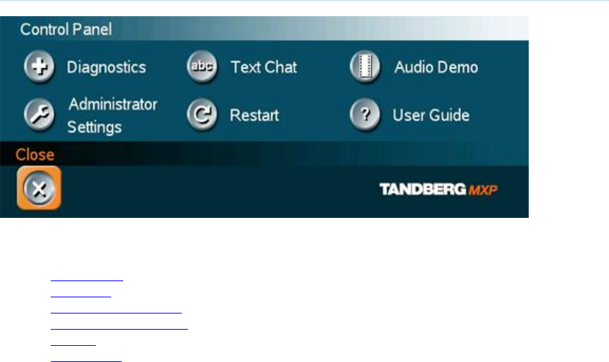
TANDBERG 3000 MXP
88
3.13 Control Panel
The Control Panel contains the features:
Diagnostics
Text Chat
Audio Demonstration
Administrator Settings
Restart
User Guide
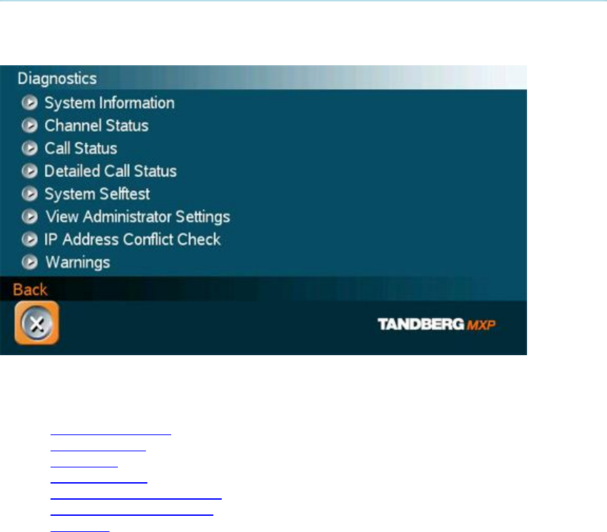
General Use
89
3.13.1 Diagnostics
Diagnostics allows testing of individual system components and displays the current system
settings.
Diagnostics contain:
System Information
Channel Status
Call Status
System Selftest
View Administrator Settings
IP Address Conflict Check
Warnings

TANDBERG 3000 MXP
90
3.13.2 System Information
Select System Information to view system numbers, line status, software version, hardware serial
number and other useful information. Press arrow key up and down to scroll in the System
Information list.
System Information contains:
System Name
My ISDN Number
My IP Number
My IP Address
MultiSite number
2
MultiSite number
3
Software
Version
Internal Test
Software
Options
installed
Network
Lines active
Lines not active
Hardware
Serial
Number
MAC address
Ethernet
Speed
Note that the serial number is also found on a sticker on the system. It is
essential for identifying the system when it comes to service contracts or
other support activities. The serial number format is xx.xxxxx.

General Use
91
3.13.3 Channel Status
Comprehensive information about the call progress is available through the Channel Status
window. This window indicates the various stages each B-channel goes through whilst
establishing a connection.
Status -
BRI Comments
Idle
Calling
Connected
Sync
Active
Releasing
Released
the channel is idle
when calling — the network has acknowledged the call
when connection is established
when the channels are synchronized
when all available channels are connected
waiting for the network to confirm a release of the call
when disconnected - the network has acknowledged the disconnection
Cause codes
The most common cause codes (for ISDN) are:
1
2
16
17
18
21
28
29
31
34
41
58
65
69
81
88
100
102
127
255
Unallocated (unassigned) number
No route to specified transit network (WAN)
Normal clearing
User busy
No user responding
Call rejected
Invalid number format (incomplete number)
Facility rejected
Normal, unspecified
No circuit/channel available
Temporary failure
Bearer capability not presently available
Bearer service not implemented
Requested facility not implemented
Invalid call reference value
Incompatible destination
Invalid information element contents
Recovery on timer expiry
Internetworking, unspecified
TANDBERG specific. undefined cause code

TANDBERG 3000 MXP
92
3.13.4 Call Status
Comprehensive information about the call is available through the Call Status window. The menu
has two columns, one for transmitted and one for received audio/video/data information. If Dual
Stream or MultiSite is available on your system and in use, pressing the UP/DOWN keys will
show one page per connected site. Some of the information fields will vary dependent on if H.320
(ISDN calls) or H.323 (IP calls) are made.

General Use
93
3.13.5 System Selftest
The system performs a check to determine internal hardware integrity. System Selftest is useful
when you want to check if your network connection is active.

TANDBERG 3000 MXP
94
3.13.6 View Administrator Settings
This window displays all the system settings. Use the arrow key on the remote control to scroll
through the list.
View Administrator Settings may contain*:
General Settings System Name
Language
Dual Monitor
Auto answer
Max Call Length
Access Code
Incoming MCU calls
Incoming Telephone calls
Far End Control
Fallback to Telephony
Screen Settings
TV Monitor Format
Picture Layout
VGA Monitor Format
VGA Out Quality
PC Picture Format
Allow VGA 50Hz
Software Options Options Installed
Serial Number
Current Option Key
Menu Settings
Menu Timeout in Call
Welcome Menu
Welcome Picture
Logo
Balloon Help
Display Welcome Text
Welcome Text
Administrator Password
Presentation Settings
Duo Video Mode
Start up Video Source
Presentation Source
Snapshot Source
Auto Display Snapshot
PIP Appearance
PIP Placing
VNC Settings
Address
Display Number
Call Quality
Video Algorithm
Audio Algorithm
Interlaced
Video Quality Main Camera

General Use
95
PC
Document Camera
VCR
AUX
VNC
Split Screen
Default Call Settings
Call Type
Network
Bandwidth
Restrict (56k)
Auto H320 Bandwidth
Auto H323 Bandwidth
SIP
Audio Settings
Inputs Mic1
Mic2
Mic3
Audio4
Audio5
Audio6
Mix Mode
VCR Ducking
Level Settings Mic1
Mic2
Mic3
Audio4
Audio5
Audio6
Outputs
Out1
Out2 (AUX)
Out3 (VCR)
Out1 Mode
Level Settings Out1
Out2 (AUX)
Out3 (VCR)
Echo Control Mic1
Mic2
Mic3
Audio4
Audio Levelling (AGC) Mics
Audio5 (AUX)
Audio6 (VCR)
Received Audio
Alert Tones & Volume Video Call Alert Tone
Telephone Alert Tone
Alert Volume
Alert Speaker
Key Tones
Video Settings
Camera Tracking Mode
MCU Status Line
Web Snapshot
MultiSite Picture Mode
Picture Control Focus

TANDBERG 3000 MXP
96
White balance
Brightness
Video Name Main Cam
AUX
Doc Cam
VCR
PC
VGA
VNC
Network Type ISDN-BRI\PRI\Leased E1\T1\Enternal
H331
ISDN Switch Type ETSI (Euro ISDN),…
Line1 Setup On
Number1
Number2
SPID1
SPID2
Line2 Setup On
Number1
Number2
SPID1
SPID2
Line3 Setup On
Number1
Number2
SPID1
SPID2
Advanced ISDN Settings Subaddress
Validate Numbers (MSN)
Parallel Dial
Send Own Numbers
Sending Complete
ISDN-PRI Settings
Number Range
ISDN-PRI Switch Type
Channel Hunting
Max Channels
Low Channel
High Channel
Search High, Low
Line Settings:
T1 Cable Length 1
T2 Cable Length 2
E1 CRC-4
Advanced ISDN PRI Settings NSF Code Video
NSF Code Telephone Call
Leased E1/T1 Settings
Call Control
Network Interface
Max Channels
Start Channels
T1 Line Coding
Line Settings
External network configuration
Call Control RS66
RS449/V.35 Compatible
IP Settings IP assignment

General Use
97
IP address
IP subnet mask
Gateway
Ethernet Speed
H.323 Settings E.164 Alias
Use Gatekeeper
Gatekeeper IP
H.323 Prefix
Advanced H.323 Settings
RSVP
NAT
NAT Address
QoS
IP Precedence Audio
Video
Data
Signaling
IP Type of Service (TOS)
Diffserv Audio
Video
Data
Signaling
SNMP Settings SNMP Trap Host1
SNMP Trap Host2
SNMP Trap Host3
SNMP Community
Streaming Settings Address
Address Port
TTL/Router Hops
Streaming Source
Allow Remote Start
Announcements
Video rate (kbps)
Network Profiles
Auto
H.320
H.323
Network Profile 4
Network Profile 5
Network Profile 6
Security Encryption
Encryption mode
Data Port 1
Baud rate
Parity
Databits
Stopbits
Mode
Data Port 2 Baud rate
Parity
Databits
Stopbits
Mode
* The administrator settings available will vary within the MXP system range depending on system and what software
options installed.

TANDBERG 3000 MXP
98
3.13.7 IP Address Conflict Check
The system will give a warning if there is an IP conflict. The user may initiate this check by
selecting IP Address Conflict Check.
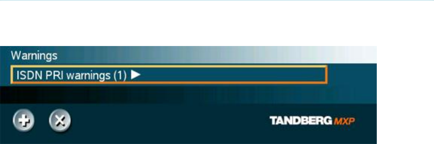
General Use
99
3.13.8 Warnings
Any warnings registered by the system will be displayed in the Warnings menu. Open a warning
in the list to get more information about the warning.
The following warnings may be displayed if detected by the system, depending on system type
and configuration:
ISDN BRI warnings
ISDN is enabled on BRI line x, but the line is not connected. Please check your network
connection or disable the line. (101)
There is something wrong with ISDN BRI line x. Please check your network connection.
(102)
IP network quality warnings
The system is experiencing packet loss in the IP network. This may affect the quality of
the call.
The system is experiencing high jitter in the IP network. This may affect the quality of the
call.
The system is dropping IP packets due to latency in the network. This may affect the
quality of the call.
ISDN PRI warnings
ISDN PRI is configured for this system, but the line is not connected. Please check your
network connection or disable the network. (131)
There is something wrong with the ISDN PRI line (Blue alarm). Please check your
network connection. (132)
There is something wrong with the ISDN PRI line (Yellow alarm). Please check your
network connection. (133)
There is something wrong with the ISDN PRI line (D-Channel not active). Please check
your network connection. (134)
External Network warnings
External Network is configured for this system, but the line is not connected. Please
check your network connection or disable the network. (161)
Leased E1/T1 warnings
Leased E1/T1 is configured for this system, but the line is not connected. Please check
your network connection or disable the network. (191)
TANDBERG 3000 MXP
100
There is something wrong with the Leased E1/T1 line (Blue alarm). Please check your
network connection. (192)
There is something wrong with the Leased E1/T1 line (Yellow alarm). Please check your
network connection. (193)
H323 gatekeeper warnings
Could not register to the gatekeeper.
The gatekeeper rejected to register the system. Another system is already registered with
the same alias or H.323 ID.
The max capacity on the gatekeeper is reached. Registration failed.
Tried to register to the gatekeeper without a valid alias. Registration failed.
The system is not allowed to register with this gatekeeper.
Can not find the gatekeeper. Check the gatekeeper configurations on the system.

General Use
101
3.13.9 Text Chat
While in an ISDN or IP call to another system supporting Text Chat (T.140), select Text Chat from
the Control Panel. Enter text in the displayed window.
How to use Text Chat:
1. Choose Text Chat from the Control Panel to open the Text Chat window.
2. Enter text with the number keys like on a mobile phone. The text is sent to the far end
continuously letter by letter.
3. Press OK to end Text Chat and escape from the text chat window.
Note that Text Chat is supported in point to point calls only.

TANDBERG 3000 MXP
102
3.13.10 Audio Demo
Note that the Audio demo will only appear in the User Guide if a Digital Natural Audio Module
is connected to the codec.

General Use
103
3.13.11 Administrator Settings
Administrator Settings contains the configuration of the whole system. It is recommended to
password protect Administrator Settings to prevent occasional users from making changes to the
system. See Administrator Settings for further details.

TANDBERG 3000 MXP
104
3.13.12 Restart
Restart the system by pressing the Restart button. You are prompted with a dialog box saying:
Do you want to restart the system? Press OK to restart, press Cancel (X) to abort.
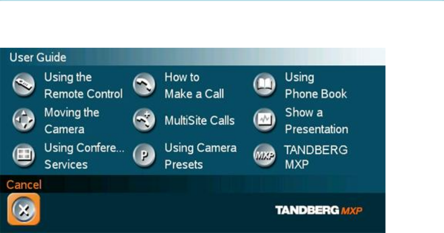
General Use
105
3.13.13 User Guide
The on screen user guide takes you through a quick step-by-step introduction to
videoconferencing. It gives the user basic skills in how to use the system.
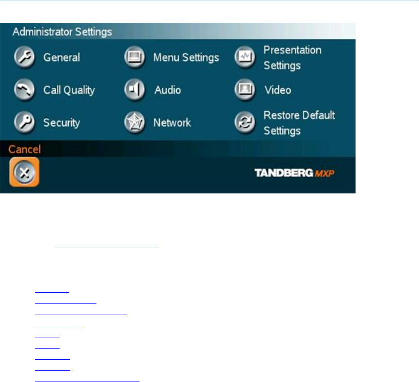
106
4 Administrator Settings
Administrator Settings contain all the settings of the system. Making changes to Administrator
Settings will change the behavior of the system. It is recommended to password protect the
access to Administrator Settings to prevent occasional users from making crucial changes to the
system, see Administrator Password.
Administrator Settings contain:
General
Menu Settings
Presentation Settings
Call Quality
Audio
Video
Security
Network
Restore Default Settings
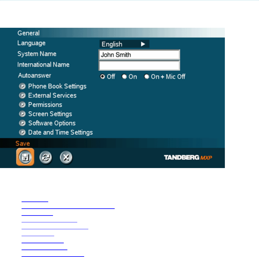
Administrator Settings
107
4.1 General Settings
When installing the system, go through the General Settings menu to ensure that you have the
right settings for your system, see System Configuration.
General Settings contain:
Language
System Name / International Name*
Autoanswer
Phone Book Settings
External Service Settings
Permissions
Screen Settings
Software Options
Date and Time Settings
* This field is only visible if the system name contains Asian and non-Latin character text input.

TANDBERG 3000 MXP
108
4.1.1 Language
The system supports 16 different languages for its on-screen menus; English, German, French,
Norwegian, Swedish, Italian, Spanish, Portuguese, Russian, Finnish, Chinese Simplified, Chinese
Traditional, Japanese, Korean, Thai and Arabic. Select the preferred language and press OK to
save.
Note that pressing the Phone Book button 5 times followed by the number button 1 on the remote
control will reset the menu language to English.

Administrator Settings
109
4.1.2 System Name
System Name identifies the system:
On the welcome page.
During an MCU conference call.
When using the Web-interface.
When the codec is acting as an SNMP Agent.
Towards a DHCP server.
H323 ID. Other systems can call in using this name instead of IP-number/IP-address.
System Name is blank by default. System name can be alphanumeric and up to 50 characters
long. Follow the installation procedure to enter a System Name.
Note that if the system name contains Asian and non-Latin character text input, the
International Name using Latin characters only, must be specified as well.

TANDBERG 3000 MXP
110
4.1.3 International Name
If the System Name contains Asian and non-Latin character text input, the International Name
using Latin characters only, must be specified as well. This is in order to make other systems
understand the system name.

Administrator Settings
111
4.1.4 Auto Answer
The auto answer setting decides whether an incoming call is put through automatically or
manually.
On The system will automatically answer all incoming calls.
On+Mic
Off The system will automatically answer all incoming calls and switch the
microphone off when the call is connected. Press Mic Off to switch the
microphone on.
Off You must manually answer all incoming calls by pressing OK or the Call key.

TANDBERG 3000 MXP
112
4.1.5 Phone Book Settings
Corporate Directory
On The Corporate Directory is available in the menu.
Off The Corporate Directory is hidden from the menu and is unavailable for users.
IP address
Enter the IP address of the management system that provides the Phone Book.
Path
The Path indicates the function of the management system.

Administrator Settings
113
4.1.6 External Services Settings
External Services
On When set to On External Services are available.
Off When set to Off External Services are unavailable.
IP address
Enter the IP address of the service provider for External Services.
Path
Enter the Path to the External Services provider.
The services available are defined by the service provider.
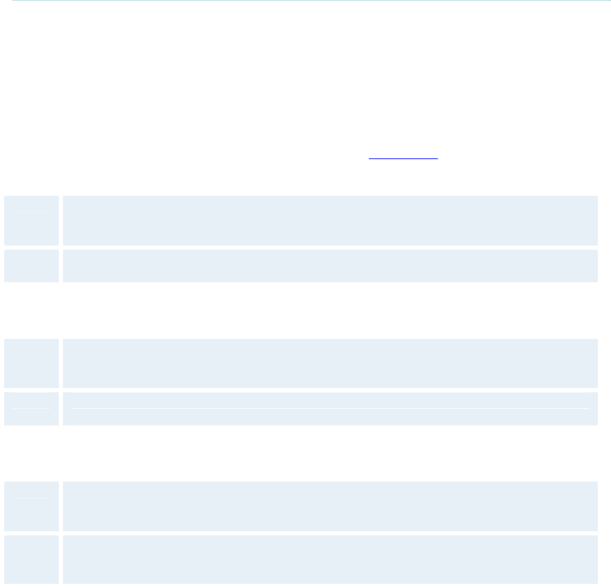
TANDBERG 3000 MXP
114
4.1.7 Permissions
Permissions contains settings for incoming MCU Calls, incoming telephone Calls, Far End
Control, Remote Software Upgrade and Fallback to Telephony.
Access Code
An access code will help you control the use of the system. All users must enter a code to identify
themselves and the call will be charged on their account. Access Codes are handy for group
systems where there are more users or divisions that share the costs of using the system. Access
Code can be set to "On" and "Off". Please refer to section Appendix 5 for more information on
Access codes.
On When making a call, an Access Code dialog box will be shown. The user must enter
the correct password in order to put the call through.
Off No password is necessary to make a call.
Incoming MCU Calls
On When you are in a call, the system will provide visual and audible indications of an
incoming call and ask you to accept/reject the call.
Off The system will not accept incoming calls when you are in a call.
Incoming Telephone Calls
On The system will accept incoming telephone calls.
Off The system will not accept incoming telephone calls. This is useful to prevent
incoming calls from systems other than videoconferencing systems.
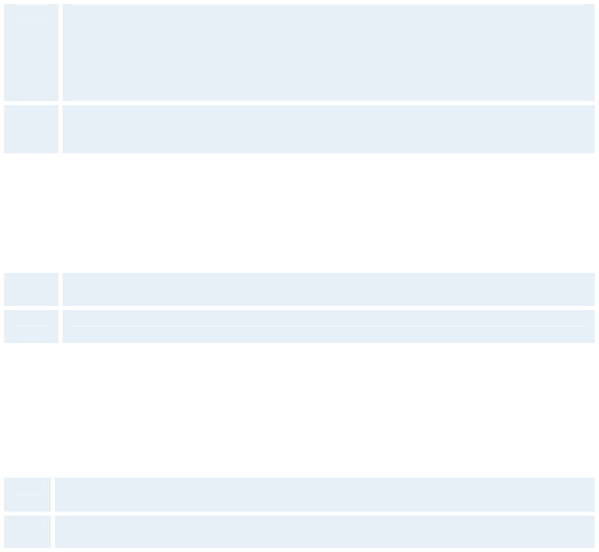
Administrator Settings
115
Far End Camera Control
On The far end will be able to:
• Control your camera
• Select your video sources
• Activate your camera presets
• Request snapshots
Off The far end can access none of the four features above on the local system. You will
however still be able to control the camera on the far end.
Fallback to Telephony
When dialing a number and the system fails to place a video call to the number dialed, the
system will attempt to place a telephone call if Fallback to Telephony is enabled.
On Enables fallback from video calls to telephone calls.
Off Disables fallback.
Far End ISDN System Upgrade
It is possible to upgrade software remotely, i.e. a far end system may upgrade software on a local
system via http on ISDN. The system to be upgraded must be configured to allow remote
software upgrade. It is possible to set a password which is needed for the far end system to be
able to accomplish the software upgrade.
On The system will allow a remote system to upgrade local software.
Off The system will not allow a remote system to upgrade local software.
Note that the configuration can also be done via the telnet or the serial port.
Maximum Call Length (minutes)
This feature will automatically end both incoming and outgoing calls when the call time exceeds
the specified Max Call Length. Max Call Length can have the following values: 0-999 (minutes),
where 0 means off.

TANDBERG 3000 MXP
116
4.1.8 Screen Settings
Auto Layout
On
If Auto Layout is On the system will change layouts automatically depending on the
number of participants in a call and if you have a dual video stream or not. Please
refer to Layout for more information.
Off
If Auto Layout is Off there will be no automatic layout changes during a call. All
desired layout changes must be done manually.
Note that when you receive low resolution images (176x144 pixels or less) the screen will
automatically adjust to a smaller view to give optimum quality experience.
Use Screen as Local PC Monitor
Use the Selfview button to switch from local PC display to standard conference layout.
On If Local PC Display is On you will be able to have Local PC displayed both outside
a call and in a call.
Off
If Local PC Display is Off you will not be able to see a Local PC image.
Note that this applies to single monitor systems only.
Please refer to Local PC Display for more information.
Dual Monitor
TANDBERG systems can be used with both one and two monitors. If you use two monitors, make
sure that Dual Monitor is set to "On".
On Selfview, snapshots and Dual Stream will be displayed on the second monitor.
Off The second monitor shows selfview only.
Picture Layout
The Advanced Picture Layout is related to the Layout button on the remote control and it can be
used at any time to change the screen layout. For wide screen systems POP mode is
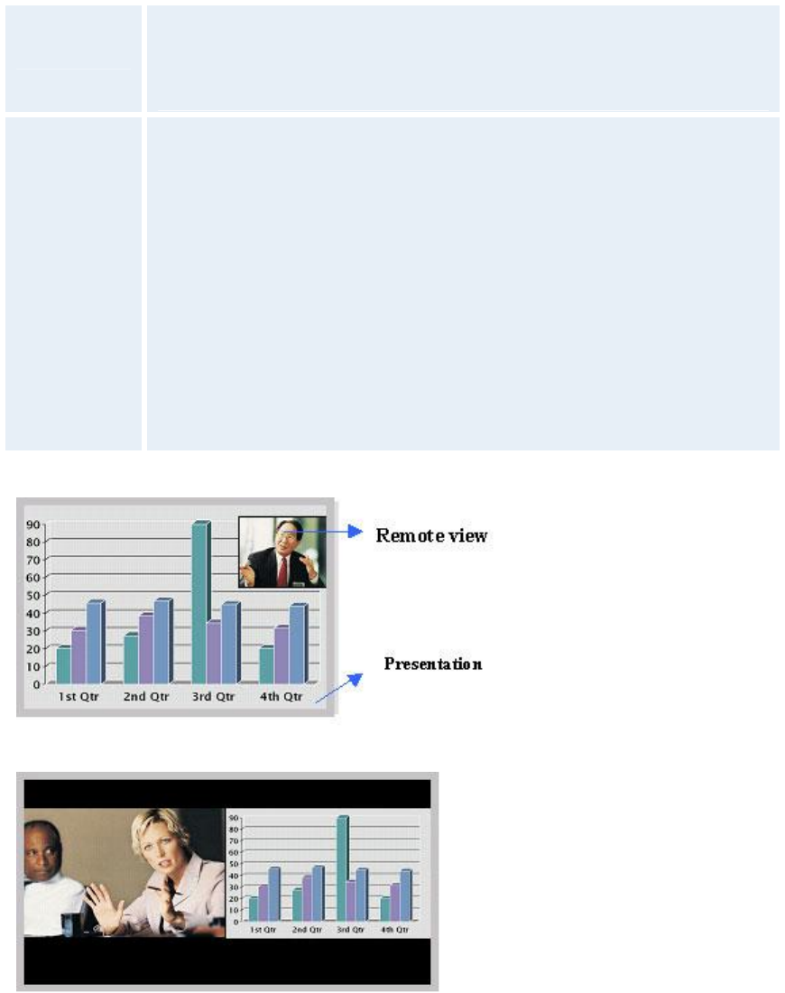
Administrator Settings
117
recommended. You will get optimized picture layouts for wide screen by pressing the Layout
button on the remote.
Picture in
Picture (PIP)
Pressing the Layout button on the remote will result in an extra picture in
smaller view (Picture in Picture). Press the Layout button to move it around
in the corners of the screen and finally hide it. Pressing and holding Layout
for 1 second will hide the small picture directly from any position.
Picture
outside
Picture
(POP)
Press the Layout button to see the images side-by-side, e.g. 1+1 layout,
where the far end and near end are displayed as images of equal size, see
figure below.
Press the Layout button once more to change to 1+2 layout. The far end
image will be displayed as the main video, with the near end, usually the
user of the system, as a smaller image in the upper right corner. If Duo
Stream is used, the Dual Stream image is displayed as the main image and
the far end and near end as smaller images to the right, see figure below for
an example.
Press the Layout button again to get the 1+3 layout.
The next time the Layout button is pressed, the normal full screen view of
the far end is displayed. Pressing and holding Layout for 1 second will
always bring you back to full screen.
Example of Picture in Picture.
Example of 1+1 Side-by-Side view (wide screen).
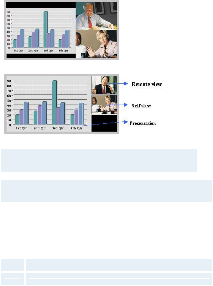
TANDBERG 3000 MXP
118
Example of 1+2 Picture outside Picture (wide screen).
Example of 1+3 Picture outside Picture (wide screen).
Note that if both TV monitor format and VGA format is set to Normal, the system will
skip the 1+3 layout, which is not beneficial for 4:3 monitors.
Note that the following menu settings do not apply for all TANDBERG MXP systems. Please
refer to the actual menu page on your system.
TV Monitor Format (wide screen monitors only)
To fully leverage your wide screen display, activate the Native 16:9 format by setting the TV
Monitor Format to Wide. Note that you should only change this setting if your TV monitor is a
wide screen (16:9) monitor or projector. All composite- and s-video output formats will then be
optimized for Wide Screen TV monitors.
Normal Output format is optimized for Normal TV monitors (4:3)
Wide Output format is optimized for Wide TV monitors (16:9)
VGA Monitor Format
To fully leverage your wide screen display, activate the Native 16:9 format by setting the VGA
Monitor Format to Wide. Note that you should only change this setting if your VGA monitor is a
Administrator Settings
119
wide screen (16:9) monitor or projector. The VGA and DVI output will then be optimized for Wide
Screen VGA and High Definition (HD) display.
Normal Output format is optimized for Normal VGA monitors (4:3)
Wide Output format is optimized for Wide VGA monitors (16:9)
Wide screen VGA or TV monitor in Normal (stretched) mode.
Wide screen VGA or TV monitor In Wide (native) mode.
VGA Out Mode
VGA Out Mode makes it possible to specify which signal to send to the VGA/DVI output.
Main Should be used if you want to use a VGA monitor as your main monitor.
Dual Should be used if you want to use a VGA monitor as your dual monitor.
VGA Out Quality*
The supported range of VGA formats will be optimized for the VGA display monitor based on the
source image.
VGA Out Quality enables the user to change the preferred format for the DVI/VGA output. It is
recommended to keep this setting in Auto unless your screen doesn’t support some of the XGA
or SVGA formats the system is using. Note that the VGA Out port support VESA Power
Management.
TANDBERG 3000 MXP
120
Auto VGA output format will be optimized dependant of the video source format,
refresh and of the EDID information available.
Supported formats are:
SVGA (800x600) 75Hz
XGA (1024x768) 60Hz / 75Hz
WXGA (1280x768) 60Hz
SVGA 800x600
75Hz VGA output format is forced to SVGA format (800x600) 75Hz
XGA 1024x768
60Hz VGA output format is forced to XGA format (1024x768) 60Hz
VGA Out Quality for Wide XGA:
If VGA Monitor Format is set to Wide, PC Picture Format is set to Normal, VGA Out
Quality is set to Auto, the layout on the monitor is either fullscreen or POP, and the
input source to the largest window is PC with resolution 1024x768, the system will use
WideXGA (1280x768) instead of XGA, when the monitor supports this.
PC Picture Format (wide screen monitors only)
PC Picture Format setting only takes effect when TV or VGA Monitor Format is set to Wide. Use
this setting to determine if you want your PC presentations to be shown stretched in full screen,
or with correct aspect ratio using part of the widescreen display. With the VGA Out Quality set to
Auto the presentation will be of the best possible quality supported by the monitor.
Normal VGA output will have 4:3 aspect ratio on wide screen monitor.
Wide
VGA output will utilize the wide screen monitor at full.
PC presentation shown in Normal (correct ratio) mode.
Administrator Settings
121
PC Presentation shown in Wide (stretched) mode.

TANDBERG 3000 MXP
122
4.1.9 Software Options
The system requires a valid option key to activate MultiSite and/or Presenter functionality. In
order to activate additional bandwidth, you need to enter a bandwidth key. A restart of the system
is required after entering a new option and/or bandwidth keys. If the key is invalid, the original key
will be used.
The following options are available:
1. No option
2. Presenter
3. MultiSite + Presenter
4. Bandwidth options

Administrator Settings
123
4.1.10 Date and Time Settings
NTP IP
This is the NTP time server address from which the system can get updated time information.
See IP Services for more details.
Auto
The NTP IP address is set automatically.
Manual
The NTP IP address is set manually.
IP Address
The IP Address for obtaining the date and time information.
Time Zone
Select the correct time zone for the location of your system.
Date Format
Choose between DD/MM/YY, MM/DD/YY, or YY/MM/DD as the desired date format.
Time Format
Select 12h or 24h time format.
Daylight Savings
On
Automatically adjust for daylight savings changes.
Off
Do not adjust for daylight saving changes.
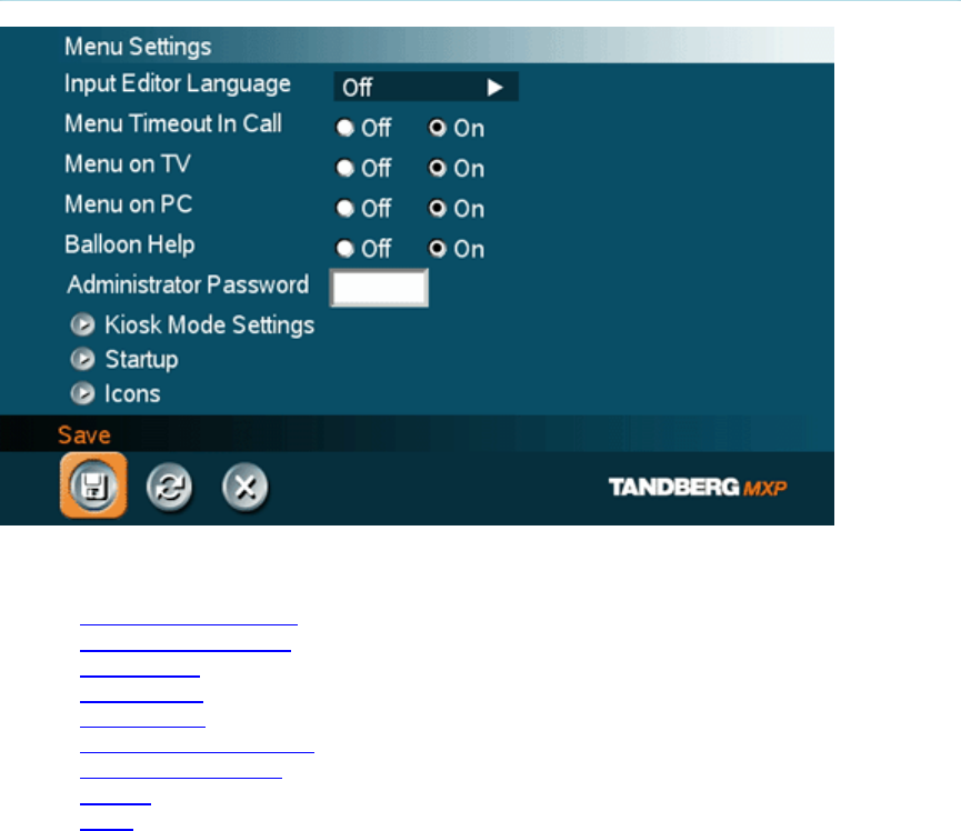
TANDBERG 3000 MXP
124
4.2 Menu Settings
Menu Settings contain the settings:
Input Editor Language
Menu Timeout In Call
Menu on TV
Menu on PC
Balloon Help
Administrator Password
Kiosk Mode Settings
Startup
Icons

Administrator Settings
125
4.2.1 Input Editor Language
When the Input Editor Language is set to Chinese, Korean or Japanese the user will be able to
enter Chinese / Korean / Japanese characters into an input field like the System Name or Phone
Book, using the remote control.

TANDBERG 3000 MXP
126
4.2.2 Menu Timeout In Call
The Main menu appears on the bottom line of the screen. Set Menu Timeout In Call to On if you
want the menu to time out automatically when you are in a call.
On The menu will time out automatically after 15 seconds if there is no activity on the
remote control. Menu timeout does only apply when you are in a call. Outside a call,
the menu will not time out.
Off The menu will not time out automatically. Press Cancel (X) to hide the main menu
manually.

Administrator Settings
127
4.2.3 Menu on TV
The Menu on TV setting decides if the menu shall be displayed on the TV screen or not. For
optimal layout of the menu, Menu on TV should be Off if Menu on PC is On and vice versa.
On The menu is available on the TV screen.
Off The menu is not available on the TV screen.
Note that if the menu has disappeared from the connected monitor or PC screen and only one of
them is connected to the system, it is possible to press the Phone Book 5 times and then the
number button 2 in order to display the menu on the connected screen.

TANDBERG 3000 MXP
128
4.2.4 Menu on PC
The Menu on PC setting decides if the menu shall be displayed on the PC (VGA screen) screen
or not. For optimal layout of the menu, Menu on TV should be Off if Menu on PC is On and vice
versa.
On The menu is available on the PC screen.
Off The menu is not available on the PC screen.
Note that if the menu has disappeared from the connected monitor or PC screen and only one of
them is connected to the system, it is possible to press the Phone Book 5 times and then the
number button 2 in order to display the menu on the connected screen.

Administrator Settings
129
4.2.5 Balloon Help
It is possible to enable / disable the balloon help window.
On Choose On if you want help text windows to appear.
Off There will be no help text window.

TANDBERG 3000 MXP
130
4.2.6 Administrator Password
It is recommended to put an Administrator Password on the system. The Administrator Password
can be maximum 5 digits long. The Administrator Password dialog box will pop up when you
choose Administrator Settings from the Control Panel. This will prevent occasional users from
going in to administrator settings. With an administrator password, you can ensure that your
system will behave in the same way every time and that only approved people are allowed to
make changes to the system.
Administrator Settings
131
4.2.7 Kiosk Mode Settings
Kiosk Mode
In Kiosk Mode the system is set to a simplified state where it can be controlled with just the four
arrow keys and OK. You will get a simplified on-screen menu with only basic functionality
available:
make calls (using predefined contacts in the phone book)
receive calls
end calls
adjust volume
Note that deactivating the Kiosk Mode is only possible through the web interface, telnet or
data port.
Using Kiosk Mode
Outside a call the Welcome Menu will be displayed:
Place a Call, Volume and Close.

TANDBERG 3000 MXP
132
If Language Menu is enabled you will first see the language selection menu. Select language and
the Welcome Menu will be displayed with your desired language.
In a call, the system will display Far End video in full screen. If Max Call Length is set to a value
and the system is in a call, the system will display a warning when it is 5 minutes, 1 minute and
10 seconds left of the call. If pressing OK when the system is in a call, the following menu will be
displayed: End Call, Volume and Close.
The following Kiosk Mode settings allows you to make some adjustments to the system's
behavior in Kiosk Mode.
Kiosk Mode - Language Menu
On When On the system will display the language menu as the first menu in kiosk mode.
Off When Off the system will display the welcome menu in English (default).
Kiosk Mode - Available Languages
In Kiosk Mode the system supports 7 different languages for its simplified on-screen menu;
English, German, French, Norwegian, Swedish, Italian and Spanish. Select the preferred
language.
Administrator Settings
133
Kiosk Mode - Auto Dial*
On The system will automatically dial to the first contact in the Phone Book when he
handset is lifted. If this contact is busy, the system will call the second number in the
Phone Book and so on. If the user places the handset in the cradle, the system will
switch to Speaker Mode. Only the Far End system can end the call.
Off The system will not make a call automatically when the handset is lifted.
* Applies only to systems with handset
Kiosk Mode - Allow Use of Remote Control
Yes All keys on the remote control are enabled.
No All keys except the arrow keys and OK key are disabled.
Kiosk Mode - Phone Book
Local The system will use the Local Phone Book in Kiosk Mode.
Corporate The system will use the Corporate Directory in Kiosk Mode.
Kiosk Mode - Kiosk Menu
On The Kiosk Mode menus will appear on the screen.
Off No menus or indicators will appear on the screen.

TANDBERG 3000 MXP
134
4.2.8 Startup
Welcome Menu
The Welcome Menu contains the Main Menu, System Status, your System Name and dial in
numbers.
On The Welcome Menu is shown when the system wakes up from standby mode.
Off The Welcome Menu is not shown when the system wakes up from standby mode.
Press the OK button to open the welcome menu.
Welcome Picture
The Welcome Picture is what you see in the background of the welcome menu.
Selfview Selfview is shown in the background of the welcome menu. In most cases this
means that main camera is displayed and you can see the video image of
yourself.
Off No picture is shown in the background of the welcome menu.
Logo
It is possible to upload a company logo to the system. For more information about how to upload
a Logo, see Appendix 6. Set the Logo settings to On to display the logo.
On Choose On if you want the company logo to appear in the background of the
welcome menu.
Off The logo is not displayed.
Note: The TANDBERG Logo will be displayed if no other company logo is loaded and logo is
enabled.
Display Welcome Text
The welcome text displays your system name and dial in numbers by default. It is possible to hide
this information by choosing Display Welcome Text Off.

Administrator Settings
135
On Welcome text is displayed on the welcome menu.
Off Welcome text is not displayed on the welcome menu.
Welcome Text
You can change the welcome text to any text you like, instead of the default text. Remember that
Display Welcome Text must be On to be able to edit the welcome text.

TANDBERG 3000 MXP
136
4.2.9 Icons
The following indicator icons may be set to on or off:
Mic Off
Volume Off
On Air
Encryption
Bad Network
Telephone
See On-screen Indicators for details.
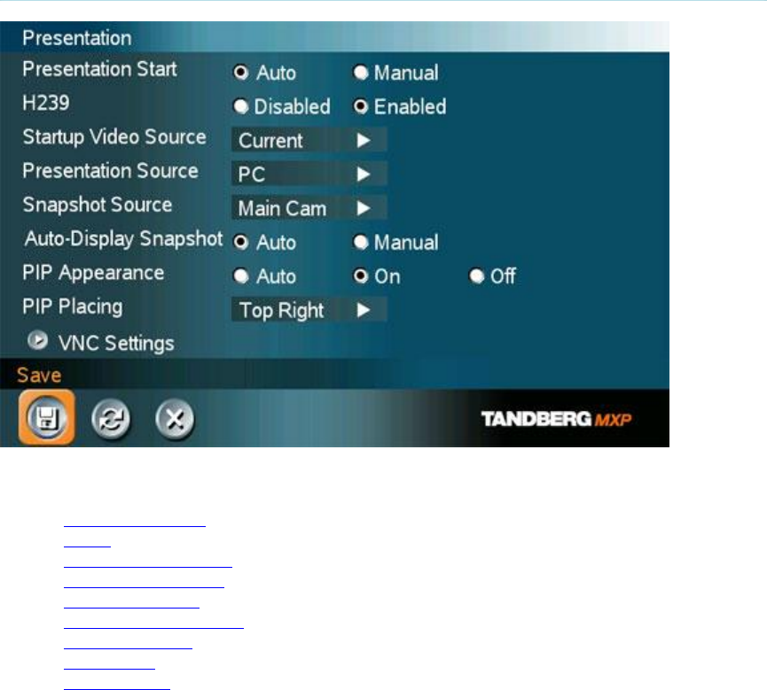
Administrator Settings
137
4.3 Presentation Settings
Presentation Settings contain:
Presentation Start
H.239
Startup Video Source
Presentation Source
Snapshot Source
Auto-Display Snapshot
PIP Appearance
PIP Placing
VNC Settings

TANDBERG 3000 MXP
138
4.3.1 Presentation Start
If your system has Dual Stream capabilities, you can show two video streams at the same time
(see also Dual Stream). Presentation Start is Auto by default. This means that you will start Dual
Stream (a second video stream) automatically when starting a presentation. Dual Stream requires
the Presenter Option and H.263 video. To check which options are installed, see the System
Information menu in Control Panel.
Manual means that you manually choose if you want to start Duo Video or not every time you
start a presentation.
Auto
Dual Stream starts automatically when you start a presentation (in other words,
when you choose a second video source). If your system or the far end system is
not capable of Duo Video/H.239, you will not use Dual Stream, but rather send the
presentation source as your Main Video
Manual
When starting a presentation, select Presentation in the call menu and select Start
Presentation. Choose a video source from the list displayed on the screen.

Administrator Settings
139
4.3.2 H.239
H.239 supports transmission of two video streams. It combines elements of Duo Video and
People+Content. If H.239 is disabled you will still be able to start TANDBERG Dual Video
Stream*
Enabled Enables H.239
Disabled Disables H.239
* The TANDBERG 550 MXP can only receive Dual Video Stream.

TANDBERG 3000 MXP
140
4.3.3 Startup Video Source
The Startup Video Source is the video source on display when the system wakes up from
standby mode. If you use Main Camera as start up source, the system will start with Main
Camera every time the system wakes up from standby, regardless of what the previous user was
using.
You can change Startup Video Source to Main Camera, PC, Document Camera, VCR, AUX,
VNC or Current depending on what video sources you have available for your system. Choosing
Current will result in the last used video source before the system went to standby.

Administrator Settings
141
4.3.4 Presentation Source
The Presentation Source is connected to the Presentation button on the remote. Pressing the
Presentation button will put the Presentation Source on display. Presentation Source is PC by
default*. You can change the Presentation Source to any video source and none. Choosing none
results in opening the Presentation menu when pressing the Presentation key.
* Only for systems with the PC video input available.

TANDBERG 3000 MXP
142
4.3.5 Snapshot Source
When you take a Snapshot, you get a snapshot of the Snapshot Source. Current is the default
Snapshot Source. This means that you take a snapshot of the video source that is currently
active.
You can change the Snapshot Source to any video source. In this way you can program the
snapshot key to apply only for PC for instance. Press Snapshot and you will take a PC snapshot
regardless of what video source that is currently active.

Administrator Settings
143
4.3.6 Auto-Display Snapshot
Select Auto to automatically display a received snapshot. Turn Auto-Display Snapshot Manual if
you wish not to have them displayed on the screen when they are sent or received. The
snapshots will be sent and received, but not displayed. With Auto-Display Snapshot set for
Manual, you must enter the Presentation menu to display a snapshot.
Auto A sent or received snapshot will automatically be displayed on the screen.
Manual A sent or received snapshot will not be displayed on the screen. To see the
snapshot, choose Display Snapshot in the Presentation menu.

TANDBERG 3000 MXP
144
4.3.7 PIP Appearance
A Picture in Picture (PIP) is a smaller picture placed in one of the corners of the screen. The PIP
enables you to see an extra picture in your video conference.
Auto PIP Auto means that Picture In Picture will appear automatically when it is suitable.
A picture in picture is nice when you use Duo Video and you need an extra window
to see all the pictures. You can of course show or hide the PIP with the Layout
button on the remote anytime.
On PIP On means that a Picture in Picture will always be displayed.
Off PIP Off means that PIP is not displayed automatically.

Administrator Settings
145
4.3.8 PIP Placing
PIP Placing lets you decide where the PIP shall appear. You can of course move the PIP with the
Layout button on the remote anytime.
Top Right PIP is placed in the Top Right corner.
Bottom
Right PIP is placed in the Bottom Right corner.
Bottom
Left PIP is placed in the Bottom Left corner.
Top Left PIP is placed in the Top Left corner.

TANDBERG 3000 MXP
146
4.3.9 VNC Settings
VNC Settings is necessary when using a VNC presentation. See chapter PC Soft Presenter and
VNC for more information on how to use VNC.
Address The IP-address of the PC with the VNC software installed. To find the IP-
address of the PC, place the mouse pointer on the VNC program icon in the
lower right corner of the Windows taskbar. You can also select Command
Prompt from the Startup-menu\Run and type cmd then enter. This will open a
command window and from here. Type “ipconfig” and press enter.
Display
Number
The display number for VNC is 0 and upwards. If you are using WinVNC,
double-click on the icon on the taskbar to view WinVNC properties. This
number should correspond with Display Number in this menu.
Password
Enter the same password as specified in WinVNC properties. The password
will be shown as asterisk signs (*) the next time you enter the menu.
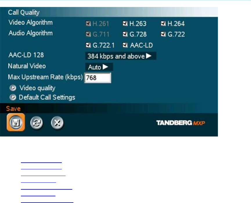
Administrator Settings
147
4.4 Call Quality
Call Quality contains the settings:
Video Algorithm
Audio Algorithm
AAC-LD 128kbps
Natural Video
Max Upstream Rate
Video Quality
Default Call Settings

TANDBERG 3000 MXP
148
4.4.1 Video Algorithm
The system will automatically select the best video algorithm based on the video source and the
capabilities of the remote system. Use this menu to disable video algorithms in case you have
interoperability issues calling other systems.
H.264 Bandwidth efficient video compression and decompression.
H.263
Normal video compression and decompression.
H.261
Legacy video compression and decompression. The system will always have H.261
enabled. Therefore it is impossible to uncheck H.261.
Administrator Settings
149
4.4.2 Audio Algorithm
The system will automatically select the best audio algorithm based on the call rate and the
capabilities of the remote system. Use this menu to disable audio algorithms in case you want to
remove “low quality” audio, or if you have interoperability issues calling other systems.
G.722 High quality audio (7 kHz at 48kbps, 56kbps or 64kbps)
G.728 Compressed normal quality audio (telephone quality, 3.1 kHz at 16kbps)
G.711 Normal quality audio (telephone quality 3.1kHz at 64kbps). This audio algorithm is
mandatory for video conferencing equipment and is impossible to uncheck.
G.722.1 Compressed high quality audio (7 kHz at 24kbps, 32kbps and 48kbps).
AAC-
LD CD-quality audio, MPEG-4 Advanced Audio Coding Low Delay (20 kHz, stereo at
128kbps, mono at 64kbps).
Call Rate vs Audio algorithms selected
Modify/remove algorithms used by unchecking the different audio algorithms.
Automatically preferred audio algorithms on call rates up to and including 192kbps
1. G.722.1 (24kbps or 32kbps)
2. G.728 (16kbps)
3. AAC-LD (64kbps or 56kbps)
4. G.722 (56kbps, 64kbps or 48kbps)*
5. G.711 (64kbps, 56kbps or 48kbps)**
6. AAC-LD (48kbps or 128kbps)
Automatically preferred audio algorithms on call rates above 192kbps
1. AAC-LD (128kbps)***
2. AAC-LD (64kbps or 56kbps)
3. G.722 (64kbps, 56kbps or 48kbps)*
4. G.722.1 (32kbps or 24kbps)
5. G.728 (16kbps)
6. G.711 (64kbps, 56kbps, 48kbps)**
7. AAC-LD (48kbps or 128kbps)
* G.722 at 64kbps is used in H.323 (IP) calls only.
** G.711 at 64kbps is used in SIP and H.323 (IP) calls only.
*** Dependent on a call rate above the AAC-LD 128 threshold. Note that this is not available on all TANDBERG systems.

TANDBERG 3000 MXP
150
4.4.3 AAC-LD 128kbps (stereo audio)
Specify a call rate for 128kbps AAC-LD. From this call rate and above, "128kbps AAC-LD" is
available. On lower call rates "64kbps AAC-LD" is available.
Stereo audio requires twice the bandwidth as mono CD-quality audio. Therefore we recommend
to enable stereo audio on high call rates only. To enable stereo CD-quality audio you need to
specify a call rate for when stereo automatically should be enabled. On lower call rates, mono
CD-quality audio "64kbps AAC-LD" will be enabled. Stereo Input mode needs to be enabled to
get stereo audio, see Stereo Settings for details.

Administrator Settings
151
4.4.4 Natural Video
Choosing Natural Video will enable 60 fields* per second true interlaced picture for high motion
video. The use of Natural Video requires the H.263+ and H.263++ video protocols. Natural video
will be disabled in H.323 MultiSite calls and in H.320 Continuous Presence MultiSite calls.
Auto Natural Video Auto will enable transmission of Natural Video from 768 kbps and
above**. Reception of Natural Video is in this case always enabled.
Off Natural Video Off will disable both transmission and reception of Natural Video.
Custom
384 kbps and above to 1920 kbps and above.
* 50 fields per second on PAL systems.
** Will transmit 448p if supported by far end system.

TANDBERG 3000 MXP
152
4.4.5 Max Upstream Rate (kbps)
The Max Upstream Rate (kbps) defines the desired maximum transmitted call rate. This is to be
able to limit the outgoing bandwidth whilst keeping the maximum incoming bandwidth, especially
useful for home offices with different upstream and downstream rates, typically ADSL.

Administrator Settings
153
4.4.6 Video Quality
The different video sources need different Video Quality Settings. Main Camera, VCR, AUX and
Split Screen have Motion as default. PC, Document Camera and VNC have Sharpness as
default.
Motion* Optimized for smooth motion video (CIF/SIF or w288p for low bandwidths,
448p/400p, Interlaced CIF (iCIF) / Interlaced SIF (iSIF) or w448p for high
bandwidths).
Sharpness* Optimized for sharp video (4CIF/4SIF, SVGA, XGA, w720p).
Auto
The system chooses the best of Motion or Sharpness depending on picture
layout and bandwidth.
4.4.6.1 Intelligent Video Management (IVM)
It is possible to configure the picture sent from the system depending upon specific requirements
and applications adding an additional level of flexibility and adaptability.
Generally, the IVM will always try to transmit the format closest to the video input format. Each
video input can be configured to either motion or sharpness:
Motion*:
When there is a need for higher frame rates, typically when a large number of participants are
present or when there is a lot of motion in the picture.
At low bit rate:
CIF will be used from a PAL video input
SIF from NTSC
w288p from wide format (HD720p) input
VGA/SVGA/XGA from PC, Digital Clarity
At high bit rate:
448p will be used from a PAL video input if Natural Video is ‘Off’ or ‘Auto’ or if
Natural Video is ‘x kbps’ and the bit rate is lower than x kbps
400p from NTSC if Natural Video is ‘Off’ or ‘Auto’ or if Natural Video is ‘x kbps’ and
the bit rate is lower than x kbps
iCIF will be used from a PAL video input, if Natural Video is ‘x kbps’ and the bit
rate is higher than or equal to x kbps
iSIF from NTSC, if Natural Video is ‘x kbps’ and the bit rate is higher than or equal
to x kbps
w448p will be used from a wide format (HD720p) input
VGA/SVGA/XGA from PC, Digital Clarity
TANDBERG 3000 MXP
154
Sharpness*:
Improved quality of detailed images and graphics, lower frame rate, ideal for enhancing quality at
lower bandwidths.
4CIF will be used from a PAL video input, Digital Clarity
4SIF from NTSC, Digital Clarity
w720p will be used from a wide format (HD720p) input
VGA/SVGA/XGA from PC, Digital Clarity
IVM Resolution
The following table shows relationship between Transmission modes selected by the system
when Motion or Sharpness is set in the Call Quality menu. IVM will use this table to optimize the
Video quality, according to the capabilities of the remote system(s):
Basic Video
Quality Video Input Transmission mode selection rules*
MOTION PAL 448p -> iCIF@50 -> CIF -> QCIF
MOTION NTSC 400p -> 448p -> iSIF@60 -> iCIF@60 ->
SIF -> CIF -> QCIF
MOTION VGA CIF -> QCIF
MOTION SVGA CIF -> QCIF
MOTION XGA CIF -> QCIF
MOTION Wide w448p -> w288p -> CIF -> QCIF
SHARPNESS PAL 4CIF -> VGA -> CIF -> QCIF
SHARPNESS NTSC 4SIF -> 4CIF -> VGA -> SIF -> CIF -> QCIF
SHARPNESS VGA VGA -> 4CIF -> CIF -> QCIF
SHARPNESS SVGA SVGA -> XGA -> 4CIF -> VGA -> CIF ->
QCIF
SHARPNESS XGA XGA -> SVGA -> 4CIF -> VGA -> CIF ->
QCIF
SHARPNESS Wide w720p -> w576p -> w448p -> w288p -> CIF
-> QCIF
Transmission mode with Motion or Sharpness selections.
4.4.6.2 Native Resolutions
The following live video resolutions are supported on the system*:
Native NTSC:
4SIF (704 x 480 pixels), Digital Clarity
400p (528 x 400)
iSIF (352 x 480 pixels), Natural Video
SIF (352 x 240 pixels)
Administrator Settings
155
Native PAL:
4CIF (704 x 576 pixels), Digital Clarity
448p (576 x 448)
iCIF (352 x 576 pixels), Natural Video
CIF (352 x 288 pixels)
QCIF (176 x 144 pixels)
SQCIF (128 x 96 pixels)
Native PC Resolutions:
XGA (1024 x 768 pixels), Digital Clarity
SVGA (800 x 600 pixels), Digital Clarity
VGA (640 x 480 pixels), Digital Clarity
Wide (16:9) Resolutions:
w288p (512 x 288 pixels)
w448p (768 x 448 pixels)
w576p (1024 x 576 pixels)
w720p (1280 x 720 pixels)
* Note that the TANDBERG 550 MXP and the TANDBERG 1000 MXP do not transmit the following video formats: 448p,
400p, iCIF, iSIF, w288p, w448p, w576p, and w720p.

TANDBERG 3000 MXP
156
4.4.7 Default Call Settings
Default Call Settings are connected with Call Settings in the call menu. If you leave Call Settings
unchanged when making a call, the system will use the Default Call Settings in the call.
In addition to the Call Settings Call Type, Net, Bandwidth and Restrict (56k), you also find settings
for H.320 Auto bandwidth and H.323 Auto bandwidth in Default Call Settings.
Call Type
Call Type can be set to:
Video Call
Telephone Call
If either the Call Type is set to Telephone Call or the Place Telephone Call
icon is selected when making a call, the call will be set up as a telephone call.
In all other cases the call will be set up as a video call.
Some network configurations may cause the setup of a video call to fail. The
call will then be set up as a telephone call instead if Fallback to Telephony is
enabled.
For MultiSite calls, Call Type enables you to specify both telephone calls and
video calls in the same conference.
Network The Network alternatives are:
Auto
ISDN
H.323
SIP
If Auto is selected, the system will select the right network depending on the
entered number:
If an IP-address (e.g. 10.12.34.56 ) is entered, H.323 is selected.
If the first digits in the number match those set in H.323 Prefix, H.323
is selected.
In other cases, ISDN (H.320) is selected.
ISDN indicates:
ISDN-BRI
If a gatekeeper is present, it is possible to place IP-calls using “telephone-
style” numbers, e.g. an E.164 alias, according to the numbering plan
implemented in the gatekeeper. The gatekeeper will then translate the dialed
number into an IP-address, see H.323 Settings for more information about
gatekeepers.
Select ISDN to ensure that the call is set up as an ISDN call.

Administrator Settings
157
Select H.323 to ensure that the call is set up as an H.323 call.
Select SIP to ensure that the call is set up as an SIP call.
Bandwidth
Bandwidth decides the quality of the video picture.
When set to Auto the system will establish a connection using a proper
bandwidth for the call, typically 384kbps for ISDN calls and 768kbps for IP
calls.
When set to Max the system will set up the call with maximum bandwidth
depending on the selected network.
Overview*
Auto: 384 kbps on ISDN/768 kbps on LAN
Max: 512 kbps on ISDN-BRI
2Mbps (1920 kbps, IP only)
1472 kbps = 23B, IP only
1152 kbps = 18B, IP only
768 kbps = 12B, IP only
512 kbps = 8B
384 kbps = 6B
320 kbps = 5B
256 kbps = 4B
192 kbps = 3B
128 kbps = 2B, Bonding/H.221
64 kbps = 1B, H.221
* Note that some software versions and networks do not support all channel selections.
Restrict
(56k) A restricted call uses 56kbps channels rather then the default unrestricted
64kbps channels.
Some older networks (primarily in the USA) do not support 64kbps channels
and require the use of restricted 56kbps calls. By default the system will dial
an unrestricted call and downspeed to 56kbps if necessary.
To force a restricted call, choose Restrict (56k) On.
H.221 or 2x64 (2x56) Calling
Some older or low end video systems do not have the ability to make bonded ISDN calls. In these
cases it is necessary to dial both ISDN numbers separately to call those systems.
These types of calls are often referred to as
H.221 calls
2x64 calls
2x56 calls
- as making 2 x 64 kbps or 2 x 56 kbps calls to the same system.

TANDBERG 3000 MXP
158
Place this type of call by:
Set Network to ISDN
Set Bandwidth to 128 kbps
A field for the 2nd number pops up in Call Settings.
Enter the second number in the Call Settings field. For 128 kbps calls that use bonding,
ignore the second number field and just enter one number to be dialed.
Using sub-address / extension address / MCU password
Sub-address is used to address different systems on the same ISDN line and is primarily used in
European Countries. LAN equivalent extension address or TCS-4 is used to address different
systems on a LAN, when dialing via a gateway.
To specify an ISDN sub-address or its LAN equivalent extension address (TCS-4), add a star (*)
after the number and then enter the sub-address/extension address.
Example:
12345678*10 ( <number>*<Sub-address/extension address/MCU password>)
When dialing IP via a gateway, the number behind the star (*) on IP might be interpreted as an
extension address.
When calling to external MCU’s requiring a password (TSC-1), this password can be added after
the star (*). If no password is specified, the user will be asked to enter the password (after
connecting to the MCU).
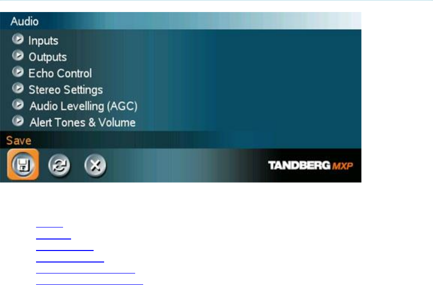
Administrator Settings
159
4.5 Audio
Audio contains the settings:
Inputs
Outputs
Echo Control
Stereo Settings
Audio Levelling (AGC)
Alert Tones and Volume

TANDBERG 3000 MXP
160
4.5.1 Inputs
Mic 1- 2 and Audio input 3-4
By default, all inputs are enabled. Just plug in an audio source and it is active. Audio inputs that
are On will automatically be mixed. Unconnected inputs will automatically be muted. Select Off to
prevent audio/noise from connected but unused inputs. The activated audio sources are stored
on camera presets.
Mic 1 and 2 are intended for electret type microphones. The microphone inputs are balanced with
24V phantom power.
Audio input 3 (AUX) is intended for connection to external playback devices, but the input can
also be configured as a microphone input by selecting Mic. When set as a microphone input it will
turn off and replace the Mic 2 input. The audio will be mixed an set up as for the Mic 2 input and
there will be an echo canceller working on the input to prevent unwanted echo to be heard at the
far end. When not configured as a microphone and connecting an external playback device to this
input there will be no echo cancelling and the audio source connected to Audio input 3 will be
heard from the local loudspeaker as well.
Audio input 4 (VCR) is intended for connection to a VCR or DVD player. It can also be connected
to other external playback devices. As there is no acoustic echo canceller on this input it should
not be connected to any microphones. The audio entering this input will be heard from the local
speaker as well. If Auto is selected, the audio from the VCR will only be heard when VCR is
selected as video source.
Mix Mode
Auto The adjustment of each microphone signal is done automatically to obtain the best
possible audio and minimize the background noise.
Fixed
Fixed will maintain a constant weighting of all microphones.
VCR Ducking
If VCR Ducking is activated, the VCR audio level will be attenuated if someone talks into the
microphone or at the far end.
The VCR ducking is only valid for audio input 4. If input 3 and 4 is configured to one stereo input
pair, see Stereo Settings, then the VCR ducking will apply to both input 3 and 4.
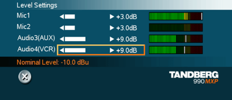
Administrator Settings
161
Level Settings
It is possible to adjust the audio input levels according to which external audio equipment is
connected. The on-screen audio level indicator will make it easier to set the correct input level
settings. The input level should be adjusted so that the average level reaches the transition
between the green and the yellow area. The audio inputs are adjustable in steps of 1.5 dB from 0
dB to 22.5 dB.
To help adjusting the input levels there is also a Peak Performance meter showing the peak
audio volume for each of the audio inputs. The level should be adjusted so that the Peak
Performance meter never reaches the maximum value to avoid the acoustic echo canceller to
malfunction due to overload of the microphone.
The default levels for Mic 1 and 2 are set for use with an Audio Technica AT871R or AT841R
microphone in an average videoconferencing room. The gain can be adjusted correctly for a wide
range of microphones.
A few examples of microphone levels are:
Audio Technica AT871R +3dB (default)
Audio Technica AT841R +3dB
TANDBERG Audio Science:
Audio Technica AT-861PZ +3dB
Crown PZM-6D +19.5dB
Audio inputs 3 and 4 are set to a default level which is adhered to by most manufacturers
of audio-visual equipment and is a level at which most audio-visual equipment (CD-players,
VCRs or DVDs) will work.
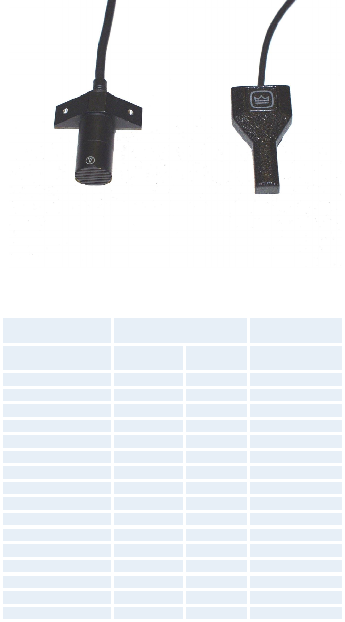
TANDBERG 3000 MXP
162
TANDBERG Audio Science microphone elements: Audio Technica AT-861PZ and Crown PZM-
6D
Signal levels -
microphone inputs Clipping level Nominal level
Input menu level
settings Vpp dBu dBu
0.0 dB 83.0 mVpp -28.4 dBu -46.4 dBu
1.5 dB 69.8 mVpp -29.9 dBu -47.9 dBu
3.0 dB 58.8 mVpp -31.4 dBu -49.4 dBu
4.5 dB 49.4 mVpp -32.9 dBu -50.9 dBu
6.0 dB 41.6 mVpp -34.4 dBu -52.4 dBu
7.5 dB 35.0 mVpp -35.9 dBu -53.9 dBu
9.0 dB 29.4 mVpp -37.4 dBu -55.4 dBu
10.5 dB 24.8 mVpp -38.9 dBu -56.9 dBu
12.0 dB 20.8 mVpp -40.4 dBu -58.4 dBu
13.5 dB 17.5 mVpp -41.9 dBu -59.9 dBu
15.0 dB 14.8 mVpp -43.4 dBu -61.4 dBu
16.5 dB 12.4 mVpp -44.9 dBu -62.9 dBu
18.0 dB 10.4 mVpp -46.4 dBu -64.4 dBu
19.5 dB 8.8 mVpp -47.9 dBu -65.9 dBu
21.0 dB 7.4 mVpp -49.4 dBu -67.4 dBu
22.5 dB 6.2 mVpp -50.9 dBu -68.9 dBu
Table1: Signal Levels - Microphone inputs

Administrator Settings
163
Signal levels -
line level inputs Clipping level Nominal level
Input menu level
settings Vpp dBu dBu
0.0 dB 15.5 Vpp 17.0 dBu -1.0 dBu
1.5 dB 13.0 Vpp 15.5 dBu -2.5 dBu
3.0 dB 11.0 Vpp 14.0 dBu -4.0 dBu
4.5 dB 9.2 Vpp 12.5 dBu -5.5 dBu
6.0 dB 7.8 Vpp 11.0 dBu -7.0 dBu
7.5 dB 6.5 Vpp 9.5 dBu -8.5 dBu
9.0 dB 5.5 Vpp 8.0 dBu -10.0 dBu
10.5 dB 4.6 Vpp 6.5 dBu -11.5 dBu
12.0 dB 3.9 Vpp 5.0 dBu -13.0 dBu
13.5 dB 3.3 Vpp 3.5 dBu -14.5 dBu
15.0 dB 2.8 Vpp 2.0 dBu -16.0 dBu
16.5 dB 2.3 Vpp 0.5 dBu -17.5 dBu
18.0 dB 2.0 Vpp -1.0 dBu -19.0 dBu
19.5 dB 1.6 Vpp -2.5 dBu -20.5 dBu
21.0 dB 1.4 Vpp -4.0 dBu -22.0 dBu
22.5 dB 1.2 Vpp -5.5 dBu -23.5 dBu
Table2: Signal Levels - Line level inputs
Note that for the dBu value for input clipping level and absolute max output level, a sine waveform
is assumed. If numbers in dBV are required, dBV value is 2.2 dB lower than the dBu value, e.q. -
10 dBu equals -12.2 dBV
Please see Interfaces for details on the audio connectors.

TANDBERG 3000 MXP
164
4.5.2 Outputs
Audio out 1 - 2
Audio out 1 is intended for connection to televisions or audio amplifiers.
Audio out 2 is intended for connection to a VCR or other recording equipment. The signal is a mix
of audio from far end and local end (except VCR in).
Note that audio out 2 never should be connected to a loudspeaker placed in the same room as
the microphones connected to the system. This will cause "howling" and possible damage to the
speaker system. If an output is Off, no audio will be sent to that output.
Out 1 Mode
If Out 1 Mode is set to Auto, the system will select analog or digital (SPDIF) mode dependent on
the detected Audio Module. If a TANDBERG Digital NAM is detected, SPDIF mode will be
selected, otherwise analog mode will be selected.
Setting the Out 1 Mode to either Analog or SPDIF will override the auto-detected mode.
See Stereo Settings for more information.
Audio Module
Select Audio Module according to the type of Audio Module installed if this is not automatically
detected. The Audio Module setting is only available if the audio module of the system is
unidentified.
Level Settings
Adjust the audio output levels according to the parameters of the external audio equipment
connected. These levels should only be adjusted when installing new audio equipment. The
default settings are correct for the TANDBERG Digital Natural Audio module and for most
consumer electronics devices (televisions, VCRs, etc.). The volume keys on the remote control
adjust the level of output 1 (the speaker output). The volume control has no effect on other
outputs.
Administrator Settings
165
Signal levels -
line level outputs* Absoolute max. output level Nominal level
Output menu level
settings Vpp dBu dBu
0.0 dB 1.2 Vpp -5.5 dBu -23.5 dBu
1.5 dB 1.4 Vpp -4.0 dBu -22.0 dBu
3.0 dB 1.6 Vpp -2.5 dBu -20.5 dBu
4.5 dB 1.9 Vpp -1.0 dBu -19.0 dBu
6.0 dB 2.3 Vpp 0.5 dBu -17.5 dBu
7.5 dB 2.8 Vpp 2.0 dBu -16.0 dBu
9.0 dB 3.3 Vpp 3.5 dBu -14.5 dBu
10.5 dB 3.9 Vpp 5.0 dBu -13.0 dBu
12.0 dB 4.6 Vpp 6.5 dBu -11.5 dBu
13.5 dB 5.5 Vpp 8.0 dBu -10.0 dBu
15.0 dB 6.5 Vpp 9.5 dBu -8.5 dBu
16.5 dB 7.8 Vpp 11.0 dBu -7.0 dBu
18.0 dB 9.2 Vpp 12.5 dBu -5.5 dBu
19.5 dB 11.0 Vpp 14.0 dBu -4.0 dBu
21.0 dB 13.0 Vpp 15.5 dBu -2.5 dBu
22.5 dB 15.5 Vpp 17.0 dBu -1.0 dBu
* Applies to Output 1 at volume setting 15.
Note that for the dBu value for input clipping level and absolute max output level, a sine waveform
is assumed. If numbers in dBV are required, dBV value is 2.2 dB lower than the dBu value, e.q. -
10 dBu equals -12.2 dBV
Please see Interfaces for details on the audio connectors.

TANDBERG 3000 MXP
166
4.5.3 Echo Control
Mic 1-2
Each of the 2 microphone inputs has a separate acoustic echo canceller. One echo canceller per
input provides more sophisticated control than having one common canceller for all microphones.
In addition to echo cancellation, the system has built-in noise reduction (NR). NR reduces
constant background noise (e.g. noise from air-conditioning systems, cooling fans etc.). In
addition, a high pass filter (Humfilter) reduces very low frequency noise.
On Echo control is normally set to On to prevent the far end from hearing their own
audio. Once selected, echo cancellation is active at all times. The echo canceller
continuously adjusts itself to the audio characteristics of the room and
compensates for any changes it detects in the audio environment. If the changes in
the audio conditions are very significant the echo canceller may take a second or
two to re-adjust.
Off You can choose to switch off the echo canceller for the available audio sources.
Echo Control should be switched Off if external echo cancellation or playback
equipment is used.
On+NR
Activates both Echo Control and Noise Reduction.
Note that it is your echo canceller that improves the audio quality experienced by the other
site. When you hear an echo of your own audio it is most likely the far end’s echo canceller
that is malfunctioning.
Tips for improving the echo canceller performance:
Place all microphones as far as possible from the loudspeakers. Minimum loudspeaker-
microphone distance should be 2 meters (6.5 ft).
It is recommended to place the microphones between 1 and 2 meters away from the
persons speaking. By using several microphones, the ratio distance loudspeaker-to-
mic/mic-to-speaker can be increased. Increasing this ratio improves the echo canceller
performance.
Place the microphones as far as possible from noise sources.
Reduce the volume setting. Ensure that the loudspeakers do not distort the audio.
The echo canceller tries to estimate the echo path from the speaker system to the
microphones. Moving objects change this path; therefore try to avoid moving objects. Be
especially aware of large objects and objects placed close to either the microphone or the
speaker system as these objects will cause severe changes to the echo path.
Avoid putting paper sheets etc. on the microphone.
Avoid moving the microphone or loudspeaker.
In the presence of low frequency noise, enable the noise reduction (NR).
Administrator Settings
167
4.5.4 Stereo Settings
Settings Output response
Out 1
Mode* Stereo input
mode Stereo
Speakers Audio out 1 Audio out 2
Analog Off Off Loudspeaker
mono VCR
Analog Off On Loudspeaker
left Loudspeaker
right
Analog On Off Loudspeaker
mono VCR
Analog On On Loudspeaker
left Loudspeaker
right
SPDIF Off Off Loudspeaker
mono VCR
SPDIF Off On Loudspeaker
L+R** VCR
SPDIF On Off Loudspeaker
mono VCR
SPDIF On On Loudspeaker
L+R** VCR
*Out 1 mode: Auto/Analog/SPDIF is described in Outputs.
**L+R = Left + Right
When Stereo Speakers is Off, the output response will be a mono loudspeaker signal on Audio
out 1 and VCR on Audio out 2 regardless on the Out 1 Mode and Stereo Input mode settings.
In analog mode the Stereo Speaker On will provide a stereo loudspeaker signal on Audio out 1
and 2.
If Stereo input mode is Off, Audio out 2 will be a mix of audio input 3, microphones and the far
end (the received far end signal is either mono, or stereo that is summed left+right into mono in
near end codec). (Note that stereo speakers set to on in analog mode will provide a different
scheme, see table above for details)
If Stereo input mode is On, Audio out 2 will be a mix of the microphones and the far end. (Note
that stereo speakers set to on in analog mode will provide a different scheme, see table above for
details)

TANDBERG 3000 MXP
168
If the system is connected to a Digital NAM, stereo sound on the loudspeakers shall be
present if a stereo input signal is connected to the inputs VCR-Left and VCR-Right or a stereo
signal is received from the Far End.
If the system is not connected to a Digital NAM, stereo sound on the loudspeaker outputs
will be present in the following situations:
If system is idle and a stereo input signal is connected to the inputs VCR-Left and
VCR-Right.
If system is in a call with mic off and a stereo input signal is connected to the inputs
VCR-Left and VCR-Right, or a stereo signal is received from the Far End.
Otherwise the Loudspeaker Left signal will be equal to Loudspeaker Right.

Administrator Settings
169
4.5.5 Audio Levelling (AGC)
On Select On to allow automatic adjustments (Automatic Gain Control) of audio levels.
When On, the AGC maintains the audio signal level at a fixed value by attenuating
strong signals and amplifying weak signals. Very weak signals, i.e. noise alone, will
not be amplified.
Off Audio levelling is not activated.
Note that to ensure correct behaviour of the AGC, it is crucial that the levels on the input
connectors are adjusted correctly using the audio input level settings. The AGC will not
compensate for severe maladjustment of input levels.
When applying a weak signal in the presence of strong background noise, the AGC might amplify
the background noise as well as the signal. Therefore, in noisy environments, it is advisable to
turn the AGC off.
Example:
In most conferences, the participants will speak at different levels, and be at different
distances from the microphones. As a result, some of the participants would be harder to hear
than others. The AGC corrects this problem by automatically increasing the microphone levels
when “quiet” or “distant” people speak, and by decreasing the microphone levels when
“louder” people speak.

TANDBERG 3000 MXP
170
4.5.6 Alert Tones and Volume
Video Call Alert Tone and Telephone Alert Tone
To help distinguish between incoming video calls and ordinary telephone calls, it is recommended
to use different ringing tones for video calls and telephone calls.
Alert Volume
You may change the volume level for the selected ringing tone.
Alert Speaker
The system also has an internal, call-alerting speaker.
On The internal speaker will warn you of an incoming call even though the monitor may
not be switched on.
Off The internal speaker is switched off.
Key Tones
On There will be a sound indicator when pressing keys on the remote control.
Off There will be no sound when pressing keys on the remote control.
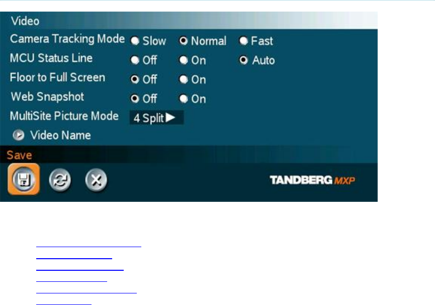
Administrator Settings
171
4.6 Video
Video contains the settings:
Camera Tracking Mode
MCU Status Line
Floor to Full Screen
Web Snapshots
MultiSite Picture Mode
Video Name

TANDBERG 3000 MXP
172
4.6.1 Camera Tracking Mode
Slow The system waits a while before zooming in on a single person speaking.
Suitable when wide-angle images are preferred over close-up images.
Normal Should be used in regular meetings.
Fast
The system quickly zooms in on a single person speaking. Suitable when close-
ups are preferred over wide-angle images.
Note that the Camera Tracking Mode entry will not be available if not using the TANDBERG
WAVE II Camera.

Administrator Settings
173
4.6.2 MCU Status Line
On The MultiSite / MCU / DuoVideo indicators will be displayed and provide information
about the conference.
Off The MultiSite / MCU / DuoVideo indicators will not be displayed.
Auto
The MultiSite / MCU / DuoVideo indicators will be displayed for a few seconds and
then timed out. When grabbing the remote control, the indicators will be shown
again.

TANDBERG 3000 MXP
174
4.6.3 Floor to Full Screen
When "Floor to Full Screen" is enabled, someone who requests floor will be seen by all
participants as full screen. When "Floor to Full Screen" is "Off", someone who request floor in a
MultiSite conference using the 5+1 layout will be seen in the large square, rather than full screen.
On
The participant that has the floor is displayed in full screen regardless of what
MultiSite layout that is used.
Off The participant that hasthe floor is displayed in the MultiSite layout that is used.

Administrator Settings
175
4.6.4 Web Snapshots
The system is able to generate JPEG snapshots and provide them when requested (as ‘http get’
or via ftp). See Appendix 6 for descriptions of the possible snapshot files.
On
Snapshots generation is enabled.
Off Snapshots generation is disabled.
Note that web snapshots are not generated if the conference is encrypted.
TANDBERG 3000 MXP
176
4.6.5 MultiSite Picture Mode
MultiSite* Picture Mode determines the default layout of a MultiSite call. Available layouts are:
Auto Split, 4 Split, 5+1 Split, and Voice Switched. You can change the layout during a call using
the layout option in MultiSite Services.
Auto Split Auto Split displays all participants on the screen simultaneously. A MultiSite
call with 3 or 4 video participants is displayed with 4 Split. A MultiSite call with
5 or 6 video participants is displayed with 5+1 Split.
Voice
Switched Voice Switched mode displays the participant that is speaking in full screen.
4 Split 4 Split displays the 4 last speaking Participants.
5+1 Split
5+1 Split displays the speaking participant in a big picture and the other
participants in small pictures.
Continuous Presence layout 4 split
Advanced Continuous Presence Layout (5+1)

Administrator Settings
177
Voice Switched mode

TANDBERG 3000 MXP
178
4.6.6 Video Name
As a default, the video inputs are given the names Main Cam, PC, Doc Cam, VCR, AUX or VNC,
dependent on what video sources are available on your system. The video names cannot exceed
eight characters. The names correspond to the video names in the Presentation Menu (Choose
Presentation from the main menu and open the Main Video or Presentation Video pop up menu).
If video names are changed, you will see the changed name appear in the Main Video and
Presentation Video menus.
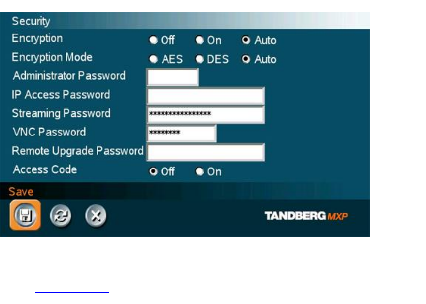
Administrator Settings
179
4.7 Security
Security contains the settings:
Encryption
Encryption Mode
Passwords

TANDBERG 3000 MXP
180
4.7.1 Encryption
(Country specific)
Auto The system will try to set up calls using encryption.
Point to point calls: If the far end system supports encryption (AES or DES), the call
will be encrypted. If not, the call will proceed without encryption.
MultiSite calls*: In order to have encrypted MultiSite calls, all sites must support
encryption. The padlock symbol will indicate encryption mode (AES or DES). If there
is a mix of AES and DES encryption, only the symbol for DES encryption (single
padlock) will be displayed. The 'closed padlock' will only be displayed on each site
when all links in the MultiSite conference are encrypted.
If the far end supports encryption, the systems will initiate encryption after the call is
connected (an ‘open padlock’ symbol will be displayed). When encryption has been
established, a ‘closed padlock’ symbol will be displayed.
On The system will only send and receive encrypted data. The call will not be
established if not all participants support encryption.
Off The system will not send or receive encrypted data.
Technical encryption information like encryption algorithm and encryption check code can be
found in the Call Status menu.
* Only available on systems with MultiSite option supported and installed.

Administrator Settings
181
4.7.2 Encryption Mode
Auto
The system will try to use the most secure encryption - AES, dependent on the
capabilities of the other sites. For sites that do not support AES encryption, DES
encryption will be tried.
AES The system will try to use AES with 128 bits encryption when setting up calls. If AES
is not supported by the other site(s), no other type of encryption will be initiated.
DES The system will always try to set up the call using DES with 56 bits encryption on
ISDN and IP. If all other sites do not support DES, no other type of encryption will be
initiated.
Both AES and DES Encryption are supported for mixed ISDN/IP calls. In addition AES -and DES
Encrypted sites can be connected at the same time.

TANDBERG 3000 MXP
182
4.7.3 Passwords
Administrator Password, IP Access Password, Streaming Password, VNC Password, Access
Code and Remote Software Upgrade password are duplicated from their respective menus.
Using the Security menu gives you a quick way to change all passwords of the system.
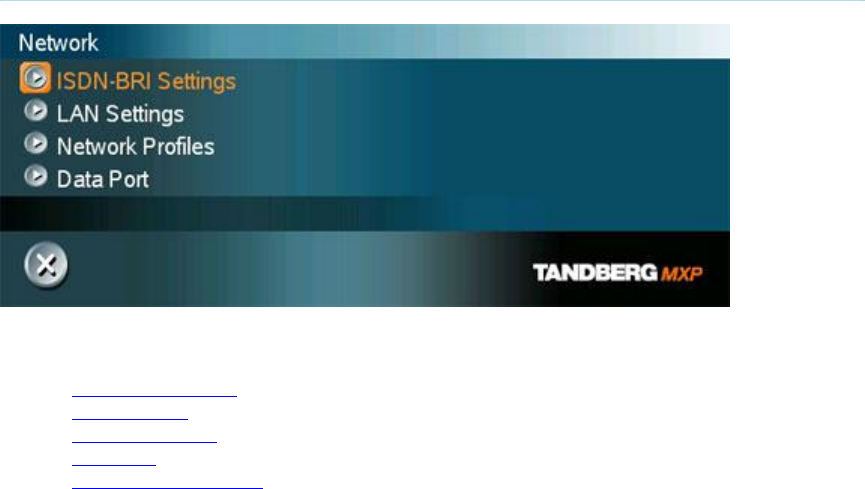
Administrator Settings
183
4.8 Network
The network menu contain:
ISDN-BRI Settings
LAN Settings
Network Profiles
Data Port
Camera Port Settings

TANDBERG 3000 MXP
184
4.8.1 ISDN-BRI Settings
To make sure your system will work properly using ISDN-BRI, make the following settings:
1. Set ISDN switch type
2. Enter ISDN line numbers (and SPIDs, if required)
3. Disable unused lines
Some software versions do not support 6 ISDN lines, therefore some of the Line Setup entries
may be grayed out.
ISDN switch type
Select the type of ISDN network connected to your unit. Note that 1TR6 should only be used if
you are operating the system behind a PABX.
Line setup
This menu allows you to program the numbers associated with your ISDN line. If you want to use
this ISDN line, you need to set Enabled On and enter the numbers of your ISDN line. If some of
the ISDN lines are not to be used, set Enabled Off. Line 1 should always be enabled. National
ISDN and AT&T Custom ISDN might require SPID numbers associated with your ISDN numbers.
If you have received two different SPID (Service Profile IDentifier) numbers for each ISDN line
from your network provider, you must program both.
Example*:
Numbers SPIDS
ISDN BRI 1: 67838498
67838498 016783849800
016783849810
ISDN BRI 2: 23478060
23478070 012347806000
012347807000
ISDN BRI 3: 23478420
23478430 012347842000
012347843000
ISDN BRI 4: 23478520
23478530 012347852000
012347853000
* Note that some systems has less than 4 BRIs available.
Administrator Settings
185
Advanced ISDN Settings
Sub address
Using a sub address enables you to connect up to eight ISDN terminals to the same ISDN
telephone number and line. The terminals are addressed by using different sub addresses. To
call a terminal with a sub address, separate the ISDN telephone number and the sub address
with a ‘*’. Note that this service has limited access on some ISDN networks.
Example: 12345678*2 (up to four digit sub addresses are possible).
Validate Numbers / MSN (Multiple Subscriber Number)
The use of MSN (Multiple Subscriber Number) enables you to attach different ISDN terminals,
with different numbers, to the same physical ISDN telephone line. If Validate Numbers is set to
On only calls to those numbers specified in the Line Setup menus will be answered. This service
can be ordered from your telephone company.
Parallel dial
On Channels will be dialed and connected in parallel when setting up a BONDING call.
Off Channels will be dialed one by one, which may increase the dialing time.
Send Own Numbers
On The system will send its own numbers to the far end.
Off The system will not send its own numbers to the far end, but please note that the
network may still send your numbers to the far end.
Sending Complete
On The system will send the ISDN message information element Sending Complete.
Off The system will not send Sending Complete.

TANDBERG 3000 MXP
186
4.8.2 LAN Settings
LAN Settings contain:
IP Settings
H.323 Settings
SIP Settings
Wireless LAN Settings
SNMP Settings
IP Services
Quality of Service
802.1X Settings

Administrator Settings
187
4.8.2.1 IP Settings
Remember to restart the system after making changes to IP Settings. This can be done by
selecting the “Save and Restart” at the bottom of the IP setting menu. Changes in IP Settings
menu will not have any effect until the system is restarted.
IP Protocol
IPv4 IP version 4 supported.
IPv6
IP version 6 supported. IP Address, IP Subnet Mask and Gateway will be disabled.
Both Both IP version 4 and IP version 6 supported.
IP-assignment
DHCP (Dynamic Host Configuration Protocol) can be selected when a DHCP server is present.
Note that for IPv6, DHCP is used for NTP / DNS Server Addresses.
DHCP IP-address, IP-subnet mask and Gateway are not used because the DHCP server
assigns these parameters.
Static The system’s IP-address, IP-subnet mask and Gateway must be specified in the IP-
address field.
IP-address
IP-address defines the network address of the codec. This address is only used in static mode. In
DHCP-mode, the assigned IP-address can be found on the Welcome Menu.
IP-subnet mask
IP-subnet mask defines the type of network. This address is only used in static mode. Your LAN-
administrator will provide the correct value for this field.
Gateway
When using DHCP, the default gateway will be set automatically. If the LAN utilizes static IP
addresses, IP address, subnet mask, and default gateway must be specified by the LAN
administrator.

TANDBERG 3000 MXP
188
Ethernet Speed
Auto The codec will auto-detect the speed/duplex on the LAN.
10/Half The codec will connect to the LAN using 10Mbps speed/Half Duplex.
10/Full 10 Mbps speed/Full Duplex.
100/Half 100 Mbps speed/Half Duplex.
100/Full 100 Mbps speed/Full Duplex.
IP Access Password
By setting an IP Access Password on the system, all access to the system using IP (Telnet, FTP
and WEB) requires a password. The default IP Access Password is “TANDBERG”.

Administrator Settings
189
DNS Settings
DNS Server 1-5
DNS Server defines the network addresses for DNS servers. Up to 5 addresses may be
specified. If the network addresses are unknown, please contact your administrator or Internet
Service Provider.
DNS Domain Name
DNS Domain Name is the default domain name suffix which is added to unqualified names.
Example:
DNS Domain Name is “example.com”, and the name to lookup is “videosystem” will result in a
“videosystem.example.com” DNS lookup.
TANDBERG 3000 MXP
190
4.8.2.2 H.323 Settings
E.164 alias
This is the E.164 address of the system. The E.164 address is equivalent to a telephone number,
sometimes combined with access codes. Valid characters are 0-9,* and #. When using a
gatekeeper, the system will send a message to the gatekeeper containing both the E.164 address
and the H.323 ID of the system.
H.323 ID
The H.323 ID of the system may be specified here. The System name is used if no H.323 ID is
entered.
H.323 Call Setup
Direct An IP-address must be dialed in order to make a H.323 call. The system will
not use a gatekeeper or CallManager
Gatekeeper The system will use a gatekeeper to make an H.323 call.
CallManager
The system will use a CallManager to make a H.323 call.
H.323 Prefix
When dialing a number prefixed with digits specified by H.323 Prefix, and with Net: Auto, an
H.323 call will be placed.
Example:
H.323 Prefix is "555". Dialing "55582" with "Net:Auto" will select LAN.

Administrator Settings
191
Gatekeeper Settings
Gatekeeper Discovery
Auto The system will automatically try to register to any available gatekeeper. If a
gatekeeper responds to the request sent from the codec within 30 seconds this
specific gatekeeper will be used. This requires auto discovery on the gatekeeper
as well. If no gatekeeper responds, the system will not use a gatekeeper for
making H.323 calls and hence an IP-address must be specified manually.
Manual The system will use a specific gatekeeper identified by Gatekeeper IP-address.
Gatekeeper IP Address
This is the gatekeeper IP-address that is used if you specify H.323 Call Setup: Gatekeeper and
Gatekeeper Discovery: Manual.
Note that if your system is part of a TANDBERG Expressway™ firewall traversal solution and
is placed outside the firewall, you should register the IP address of your Border Controller as
the Gatekeeper IP address and set H.323 Call Setup to Gatekeeper.
Authentication Mode
Auto If Authentication Mode is set to Auto and the gatekeeper indicates that it requires
authentication, the endpoint will automatically try to authenticate itself to the
Gatekeeper.
Off If Authentication Mode is set to Off the system will not try to authenticate itself to a
Gatekeeper, but will still try a normal registration.
Authentication ID / Authentication Password
The system sends the Authentication ID and Password to a Gatekeeper for authentication. The
authentication is a one way authentication from the endpoint system to a Gatekeeper, i.e. the
endpoint is authenticated to the Gatekeeper. If the Gatekeeper indicates that no authentication is
required, the endpoint will still try to register.

TANDBERG 3000 MXP
192
CallManager Settings
CallManager IP
This is the CallManager IP-address that is used if you specify H.323 Call Setup: CallManager.

Administrator Settings
193
Advanced H.323 Settings
The Advanced H.323 Settings only have an effect if they are supported by your IP infrastructure.
NAT
NAT, Network Address Translation, is used when a PC and a videoconferencing system are
connected to a router with NAT support. NAT support in the videoconferencing system enables
proper exchange of audio/video data when connected to an external videoconferencing system
(when the IP traffic goes through a NAT router). When NAT is On, the NAT Server Address will
be shown in the startup-menu: "My IP Address: 10.0.2.1".
On The system will signal the configured "NAT Address" in place of its own IP-address
within Q.931 and H.245.
Auto The system will try to determine if the "NAT Address" or the real IP-address should
be used within signalling. This is done to make it possible to place calls to endpoints
on the LAN as well as endpoints on the WAN.
NAT Address
This must be the external/global IP-address to the router with NAT support. Packets sent to the
router will then be routed to the system. In the router, the following ports must be routed to the
system’s IP-address:
Port 1720
Port 5555-
5560
Port 2326-
2365
Please contact your TANDBERG representative for further information.
RSVP
Auto Resource Reservation Protocol enables the systems to request the optimal amount
of bandwidth for the duration of an IP videoconference.
Off Resource Reservation Protocol is switched off.

TANDBERG 3000 MXP
194
H.323 Ports
Static When selecting static H.323 ports for TCP connections the ports 5555 to 5574
will be used for Q.931 and H.245 respectively.
Dynamic The system will allocate which ports to use when opening a TCP connection.
The reason for doing this is to avoid using the same ports for subsequent calls
as some firewall consider this as a sign of attack.

Administrator Settings
195
4.8.2.3 SIP Settings
Mode
On Setting the SIP mode to on will enable the system for incoming and outgoing SIP
calls.
Off Setting the SIP mode to off will disable incoming and outgoing SIP calls from the
system.
Display Name
The Display name part of the SIP Address (URI) is usually a full name or system name.
Examples:
“Alice Wonderland”
“System 01”
SIP Address
The SIP Address is the SIP URI used to address the system.
SIP Address (URI): <text field>
Examples:
“alice@example.com”
“1234”
“1234@example.com”
Server Discovery
Auto When Auto is selected, the SIP Server address is obtained using Dynamic Host
Configuration Protocol (DHCP).
Manual When Manual is selected, the manually configured SIP Server address will be
used.

TANDBERG 3000 MXP
196
Server Address
The Server Address is the manually configured address for the outbound proxy and registrar. It is
possible to use a fully qualified domain name, or an IP address. The default port is 5060 for TCP
and UDP, but another one can be provided.
Server Address: <text field>
Examples:
“sipserver.example.com”
“sipserver.example.com:5060”
“10.0.0.2”
“10.0.0.2:5061”
Authentication
User Name
This is the user name part of the credentials used to authenticate toward the SIP Server.
User name: <text field>
Password
This is the password part of the credentials used to authenticate toward the SIP Server.
Password: <text field>
Server Type
Available servers are: Auto, Nortel, Microsoft and Experimental
Current RFC’s and Drafts supported:
RFC 3261 SIP: Session Initiation Protocol
RFC 2327 SDP: Session Description Protocol
RFC 3264 An Offer/Answer Model with the Session Description Protocol (SDP)
RFC 3263: Session Initiation Protocol (SIP): Locating SIP Servers - No support for
NAPTR records.
RFC 3311 The Session Initiation Protocol (SIP) UPDATE Method
RFC 2976 SIP INFO Method
Draft-levin-mmusic-xml-media-control-03.txt - Used for video fast picture update
requests
RFC 3361 Dynamic Host Configuration Protocol (DHCP-for-IPv4) Option for Session
Initiation Protocol (SIP) Servers
RFC 3550 RTP: A Transport Protocol for Real-Time Applications
RFC 2032 RTP Payload Format for H.261 Video Streams
Draft-ietf-avt-rfc2032-bis-06.txt - Draft for advanced video signaling including
resolution and mpi.
Administrator Settings
197
RFC 2190 RTP Payload Format for H.263 Video Streams
RFC 2429 RTP Payload Format for the 1998 Version of ITU-T Rec. H.263 Video
(H.263+)
Draft-ietf-avt-rfc2429-bis-05.txt - Draft for advanced video signaling including
resolution, mpi, annexes and custom formats.
RFC 3047 RTP Payload Format for ITU-T Recommendation G.722.1
RFC3581 An Extension to the Session Initiation Protocol (SIP) for Symmetric Response
Routing
RFC3984 RTP Payload Format for H.264 Video
RFC3016 RTP Payload Format for MPEG-4 Audio/Visual Streams
Media Capabilities supported in SIP:
Audio:
PCMU (G.711 u-law)
PCMA (G.711 a-law)
G.722 64 kbps
G722.1 24kbit
G.722.1 32 kbps
Video:
H.261: QCIF 1/30, CIF 1/30
H.263: SQCIF 1/30, QCIF 1/30, CIF 1/30, 4CIF 2/30
H.263++: XGA 4/30, SVGA 3/30, VGA 2/30, SQCIF 1/30, QCIF 1/30, CIF 1/30, 4CIF 2/30

TANDBERG 3000 MXP
198
4.8.2.4 Wireless LAN Settings
SSID (Service Set Identification)
Example “WLANNETWORK”. Defines a local network id for this wireless region. It must be the
same for all end points and the access point. An endpoint will find the access point if the SSID is
correct, however if the encryption key is faulty it will not transmit any data.
Community (optional)
Community can be used when connecting to an access point where the SSID is the same.
Example “Unit2”.
WLAN Mode
AdHoc Used when not communicating with an access point.
Managed Used when communication is made through an access point.
Make sure the corresponding settings are programmed into the access point. Press “Restart”
from Control Panel in order to activate the settings.
Required cards
• Compaq WL110 11 Mbps Wireless LAN
• Lucent Orinoco 11 Mbit/s SILVER
• Lucent Orinoco 11 Mbit/s GOLD
• Cisco Aironet 350 series (AIR-PCM 350 series)
• Enterasys Networks RoamAbout 802.11 DS High Rate
• Melco Buffalo WLI-PCM-L11G
Recommended access point
• Compaq WL410 base station
Note! The PC card/PCMCIA-card used must comply with the relevant regulations for such
cards in the country where it is used. The unit must be supplied by power supply (AC-DC
adapter) powerbox SPN-270-12, which complies with the requirements for limited power
source according to IEC/EN 60950.

Administrator Settings
199
Encryption
Select Encryption if you want to use WEP encryption on your Wireless LAN connection.
Increased encryption level will decrease performance.
Use
Key Select which of the keys shown below you want to use.
Key 1-
4 The 64-bit keys can consist of a leading star (*) and 5 characters.
The 128-bit key can consist of a leading star (*) and 13 characters.
Start with a * and then the text. Example: 128 bit key: *secretkeyhome.
Encryption using Hex numbers The 64-bit keys can consist of 10 hexadecimal digits. Example:
“de01ad4dbe”. The 128-bit key can consist of 26 hex numbers.

TANDBERG 3000 MXP
200
4.8.2.5 SNMP Settings
SNMP Settings
SNMP Trap Host identifies the IP-address of the SNMP manager. SNMP (Simple Network
Management Protocol, SNMP Ver 1) is used for monitoring and configuring of different entities in
a network. The system's SNMP Agent responds to requests from SNMP Managers (a PC
program etc.). SNMP traps are generated by the agent to inform the manager about important
events.
Traps can be sent to multiple SNMP Trap Hosts. Enter the IP address of up to three SNMP
managers. All traps will then be sent to the hosts listed.
SNMP Community names are used to authenticate SNMP requests. SNMP requests must have a
‘password’ in order to receive a response from the SNMP agent in the codec. Note that the
SNMP Community name is case sensitive. The default password is "public".

Administrator Settings
201
4.8.2.6 IP Services
NTP IP
This is the NTP time server address from which the system can get updated time information.
This is a requirement for proper operation if H.235
authentication is implemented.
The Network Time Protocol (NTP) is used to synchronize the time of the system to a reference
time server. The NTP IP setting holds the IP address to a time source where the system can get
the exact time. The time server will subsequently be queried every 24th hour for time updates.
The system will use the time to timestamp messages transmitted to Gatekeepers or Border
Controllers requiring H.235 authentication.

TANDBERG 3000 MXP
202
4.8.2.7 Quality of Service
QoS Type
Off No QoS is used.
Diffserv Diffserv QoS method is used. Please see below for details.
IP
Precedence IP Precedence QoS method is used. Please see below for details.
IP Precedence Video
Used to define which priority audio, video, data and signaling should have in the network. The
higher the number, the higher the priority. The priority ranges from 0(off) - 7 for each type of
packets.
Auto will provide the following priority:
Audio
Video
Data
Signaling
4
4
3
6
IP Type of Service (TOS) helps a router select a routing path when multiple paths are available.
Delay
Tells the router to minimize the delay.
Throughput
Tells the router to maximize the throughput.
Reliability
Tells the router to maximize the reliability.
Cost
Tells the router to minimize the cost.
IP Precedence Telephony
Used to define which priority audio should have in the network for telephone calls. The higher the
number, the higher the priority. The priority ranges from 0(off) - 7 for each type of packets.

Administrator Settings
203
Auto will provide the following priority:
Audio
4
Diffserv Video
Used to define which priority Audio, Video, Data and Signaling packets should have in an IP
network. The priority ranges from 0 to 63 for each type of packets.
Diffserv Telephony
Used to define which priority Audio packets should have in an IP network for telephone calls. The
priority ranges from 0 to 63 for each type of packets.

TANDBERG 3000 MXP
204
4.8.2.8 IEEE 802.1x
802.1X
The system may be connected to an IEEE 802.1x LAN network. Supported 802.1x protocols are
EAP-MD5, EAP-PEAP and EAP-TTLS. The 802.1x authentication are enabled by setting 802.1x
Mode to On.
On 802.1x authentication enabled
Off 802.1x authentication disabled
Anonymous Identity
The 802.1x Anonymous ID string is to be used as unencrypted identity with EAP types that
support different tunneled identity, EAP-PEAP and EAP-TTLS. The anonymous ID, if set, will be
used for the initial (unencrypted) EAP Identity Request.
Identity
The 802.1x Username is the username needed for 802.1x authentication.
Password
The 802.1x Password is the password needed for 802.1x authentication.
EAP-MD5
On The EAP-MD5 protocol is enabled
Off The EAP-MD5 protocol is disabled
EAP_TTLS
On The EAP_TTLS protocol is enabled
Off The EAP_TTLS protocol is disabled
EAP-PEAP
On The EAP_PEAP protocol is enabled
Off The EAP_PEAP protocol is disabled
Note that 802.1x wireless LAN is not supported.

Administrator Settings
205
4.8.3 Network Profiles
This menu consists of 7 network profiles; a prefix can be added for each profile. If you add a
prefix to a profile, this prefix will automatically be added in front of the number being dialed.
Example:
0 is added as a Call Prefix to the 2nd profile, ISDN. If you enter 12345678 in the dial menu
and select ISDN, the number dialed will be 012345678.
Using the three last profiles you can enter the name of a profile, prefix and network selection.
This is useful if you have a fixed prefix for your service provider.

TANDBERG 3000 MXP
206
4.8.4 Data Port
The system provides up to two standard RS232 serial ports to allow a computer to be connected
for data transfer and control purposes. Note that when connecting to a PC the connecting cable
must be a straight through RS232 cable.
Baud Rate, Parity, Databits and Stopbits
If you wish to connect a PC to Data port 1, you must ensure that the PC and the system are
identically configured. The available settings are:
Baud
Rate
Parity
Databits
Stopbits
1200, 2400, 4800, 9600, 19200, 38400, 57600, 115200
None, Odd, Even
7, 8
1, 2
The control interface provided by the data port supports a subset of the Hayes command set as
well as a comprehensive set of system specific commands. It maintains communication with the
data port’s command interpreter at all times. All features available from the hand-held remote
control can be accessed through the data port.
Please see Camera Port Settings and Interfaces for details on the Camera Port on the
TANDBERG 3000 MXP Profile.

Administrator Settings
207
4.8.5 Camera Port Settings
Camera Port Mode
Auto Select Auto and the system will automatically detect WAVE cameras.
VISCA Select VISCA if using a camera supporting the VISCA protocol.

TANDBERG 3000 MXP
208
4.8.6 Restore Default Settings
Restore Default Settings will restore all administrator settings. Note that this will not affect your
Call Directory information, Network Type, Line Setup numbers or your SPID numbers.

209
5 Peripheral Equipment
Using the optional peripheral devices outlined in this chapter and the many others available, you
will be able to build your own applications for use with the system, thereby better integrating the
system into your business environment. This chapter will explain how to connect peripheral
equipment to your system. First of all however, we recommend you examine Interfaces, with
details on the available connectors on the back of the system Codec.
Peripheral Equipment contains:
Interfaces
Document Camera
VCR / DVD
Additional Cameras
Additional Microphones
TANDBERG DNAM and Speakers
Stereo Speaker Kit
Telephone Add-On
Dual Monitor
XGA Monitors and Projectors
VESA Display Power Management
Digital Monitor Power Management
Extended Display Identification
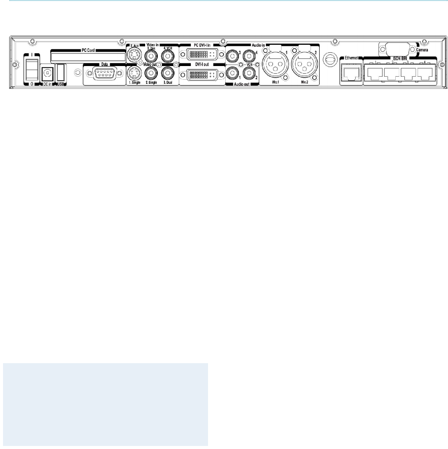
TANDBERG 3000 MXP
210
5.1 Interfaces
5.1.1 Video
5 Video Inputs
1 video input used by the camera.
1 video input supporting S-Video through a Mini-DIN connector.
2 video inputs supporting composite signals through RCA connectors.
1 VGA/DVI-I (DVI = Digital Video Interface, I = Integrated Digital & Analog) input
supporting resolutions SVGA (800x600), XGA (1024x768) and SXGA (1280x1024),
analog or digital.
Levels:
Composite: 1 Vpp, 75 ohm
S-Video (Y/C):
Y: 1 Vpp, 75 ohm
C (PAL): 0.3 Vpp, 75 ohm
C (NTSC): 0.28 Vpp, 75 ohm
The system will automatically adapt to a PAL or NTSC input.
VGA formats supported on 'DVI-I in':
SVGA (800x600) 60Hz, 72Hz, 75Hz, 85Hz
XGA (1024x768) 60 Hz, 70Hz, 75Hz
SXGA (1280x1024) 60Hz
HD720p (1280x720) 50,60 Hz
4 Video Outputs
1 S-Video output, Mini-DIN connector.
2 composite video outputs, RCA connectors.
1 VGA/DVI-I (DVI = Digital Video Interface, I = Integrated Digital & Analog) output
supporting resolutions SVGA (800x600) and XGA (1024x768), analog or digital.
The first Mini-DIN connector and the first RCA connector provide main video (incoming/outgoing
video and menus).
The other connector provide selfview/still image/Duo Video. The outputs are always active.

Peripheral Equipment
211
The format of the output will be either PAL or NTSC depending on your country’s standard video
format.
The VGA/DVI output provides either main monitor video or second monitor video depending on
menu configuration. This is the output used in a
standard 3000 MXP Profile configuration.
Levels:
Composite: 1 Vpp, 75 ohm
S-Video (Y/C):
Y: 1 Vpp, 75 ohm
C (PAL): 0.3 Vpp, 75 ohm
C (NTSC): 0.28 Vpp, 75 ohm
VGA formats supported on 'DVI-I out':
SVGA (800x600) 75Hz
XGA (1024x768) 60Hz
WXGA (1280x768) 60Hz
HD720p (1280x720) 50,60 Hz
DVI and specifications:
DVI stands for Digital Video Interface, and is a form of video interface technology made to
maximize the quality of flat panel LCD monitors and high-end video graphics cards.
The TANDBERG codec contains a DVI-I plug that can transmit either digital DVI signals or
standard analog VGA signals, depending on what type of monitor is connected.
DVI Specifications
TANDBERG DVI-I follows the VESA Monitor Timing Standard v1.08, also knows as Display
Monitor Timing (DMT).
Analog Horizontal
Frequency Vertical
frequency Pixel
Clock
800x600 @
75Hz 46.875kHz 75.00Hz 49.50MHz
1024x768
@ 60Hz 48.363kHz 60.004Hz 65.00MHz
Digital
800x600 @
75Hz 46.875kHz 75.00Hz 49.50MHz
1024x768
@ 60Hz 48.363kHz 60.004Hz 65.00MHz
DVI-I Video resolution supported in F1 and above
Supported DVI cables:
TANDBERG supports DVI-D Single-Link, DVI-A and DVI-I Single-Link format cables.
DVI-D cables transmit digital T.M.D.S. signals, DVI-A cables transmit analog VGA signals and
DVI-I cables can transmit either digital or analog signals.
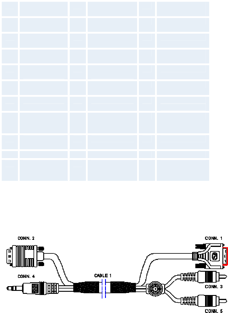
TANDBERG 3000 MXP
212
It is possible to extend existing DVI cables by the use of extension cables. The maximum cable
length however, is 5 meters. Going beyond that may result in quality loss.
Pin Signal
Assignment Pin Signal
Assignment Pin Signal
Assignment
1 T.M.D.S.
Data2- 9 T.M.D.S.
Data1- 17 T.M.D.S. Data0-
2 T.M.D.S.
Data2+ 10 T.M.D.S.
Data1+ 18 T.M.D.S. Data0+
3 T.M.D.S.
Data2/4 Shield 11 T.M.D.S.
Data1/3 Shield 19 T.M.D.S.
Data0/5 Shield
4 T.M.D.S.
Data4- 12 T.M.D.S.
Data3- 20 T.M.D.S. Data5-
5 T.M.D.S.
Data4+ 13 T.M.D.S.
Data3+ 21 T.M.D.S. Data5+
6 DDC Clock 14 +5V Power 22 T.M.D.S. Clock
Shield
7 DDC Data 15 Ground (return
for +5V, HSync
and VSync)
23 T.M.D.S. Clock+
8 Analog Vertical
Sync 16 Hot Plug Detect 24 T.M.D.S. Clock-
C1 Analog Red C2 Analog Green C3 Analog Blue
C4 Analog
Horizontal
Sync
C5 Analog Ground
(analog, R, G &
B return)
DVI-I - Combined Analog and Digital Connector Pin Assignments.
The TANDBERG Profile systems are shipped with a PC cable with integrated audio:
DVI-A Plug + 2*RCA Plug to VGA Plug + 3.5mm Stereo Plug, length 5m.
PC cable, VGA - DVI with integrated audio

Peripheral Equipment
213
Signal
name CONN.
1 CONN.
2 CONN.
3 CONN.
4 CONN.
5 Cable
color
DDC Clock 6 15 Orange
DDC Data 7 12 White
Vertical
Sync 8 14 Yellow
DDC Power
(+5V) 14, 16 9 Red
Digital
return 15 5, 10 Black
RGB Red C1 1 Red
Coax
RGB Green C2 2 Green
Coax
RGB Blue C3 3 Blue
Coax
Horizontal
Sync C4 13 Brown
RGB Return C5 6, 7, 8 RGB
Coax
Shield
Outer Shield
Ground Shell Shell Outer
Shield
Audio Left Centre Tip Audio
Black
Audio Right Ring Centre Audio
Red
Audio GND Gnd Sleeve Gnd Audio
Shield
PC cable, VGA - DVI with integrated audio

TANDBERG 3000 MXP
214
5.1.2 Audio
4 Audio Inputs
2 microphone inputs (balanced, 24V phantom powered) via XLR connectors.
2 audio inputs (line level) via RCA connectors.
All audio inputs are active by default. For further information, refer to chapter Audio.
Audio input connector specification:
Connector label Microphone(s) Audio input(s)
Signal type Balanced Unbalanced
Connector (codec) XLR-F, pin 1-gnd,
pin 2 hot, pin 3-
cold/neutral
Female RCA/phono,
sleeve-ground,
centre-signal
Input impedance 2400 ohms (pin 2 -
3) 10K ohms
Max input level when
set to minimum input
level
83 mVpp 15.5 Vpp
Max input level when
set to maximum
input level
6.2 mVpp 1.2 Vpp
Range, menu
adjustable input gain 22.5 dB (16 steps of
1.5 dB) 22.5 dB (16 steps of
1.5 dB)
Phantom power
voltage 24 V +/- 5% -
Phantom power
resistor, pin 2 1200 ohms -
Phantom power
resistor, pin 3 1200 ohms -
Max phantom power
current pr mic 12 mA
-
Peripheral Equipment
215
2 Audio Outputs
1 output (line level) via RCA connector providing audio from far end in addition to dial
tones. This output is used by the monitor. This output also supports S/PDIF.
1 VCR output (line level) via RCA connector providing a mixed signal between audio from
the local side (except from the VCR input) and audio from the far end. This output is
intended for connection to a VCR.
Audio output connector specification:
Connector label Audio outputs
Signal type Unbalanced
Connector (codec) Female RCA/phono, sleeve-ground,
centre-signal
Output impedance 680 ohms
Max output level when set
to maximum output level
and volume control set to
max.
Max output level when set
to minimum output level and
volume control set to max.
15.5 Vpp
1.2 Vpp
Range, menu adjustable
output gain 22.5 dB (16 steps of 1.5 dB)*
Volume control attenuation
(audio out 1) 0 to 21 dB + mute (steps of 1.5 dB)
* Additional attenuation is possible on room/loudspeaker audio output using the volume control
setting

TANDBERG 3000 MXP
216
5.1.3 Network
Ethernet:
1 x Ethernet (RJ-45 Jack) LAN interface (10/100 Mb) up to 2 Mbps or 2.3 Mbps depending on the
bandwidth option installed.
To connect the system to a LAN, use the Ethernet cable provided by TANDBERG (or a standard
Ethernet cable).
The cable specification is:
1 ------------ 1
2 ------------ 2
3 ------------ 3
6 ------------ 6
If no LAN is available and the codec is connected directly to a computer, use a crossover cable.
The crossover cable specification is:
If such a connection is needed, the system and the PC must use ‘static’ TCP/IP settings because
no DHCP server is controlling the small “LAN”, which has been created between the computer
and the system. When configuring a back-to-back connection between the PC and the system,
make sure both static IP addresses exist on the same subnet.
ISDN BRI Interface:
ISDN I.420 (RJ-45 Jack) Basic Rate Interface S/T (2B+D), 128 kbps per ISDN I/F
To connect the system to BRI, use the ISDN cable provided by TANDBERG (or a standard BRI
cable).
The pinout of the S/T interface is:
BRI Pinout
Pin-3 TX+
Pin-4 RX+
Pin-5 RX-
Pin-6 TX-
5.1.4 Data port

Peripheral Equipment
217
The data port(s) are implemented as Data Communications Equipment (DCE). The connector
used are female 9-pin D-subs.
Signal name Direction Pin
number
Carrier detect, CD From
DCE 1
Receive data,
RXD From
DCE 2
Transmit data,
TXD To DCE 3
Data terminal
ready, DTR From
DCE 4
Signal ground,
GND 5
Data set ready,
DSR From
DCE 6
Ready to send,
RTS To DCE 7
Clear to send,
CTS From
DCE 8
Ring indicator, RI From
DCE 9

TANDBERG 3000 MXP
218
5.1.5 Camera Port
The TANDBERG 3000 WAVE II Camera cable consists of two cables, VIDEO CABLE and
DATA/POWER CABLE
connected together at one end with DSUB CONNECTOR.
VIDEO CABLE
• Length 1900mm
• S-VIDEO connector
DATA/POWER CABLE
• Connector RJ45, 8 pin shielded modular jack
• Cable Twisted pairs 4-5, 3-6, 1-2, 7-8 color black
• Length 1920mm
VIDEO CABLE DATA/POWER CABLE connected at one end to DSUB CONNECOR.
DSUB CONNECTOR
• Male 9 pin DSUB
PINOUT DIAGRAM
.1 SIGNAL
NAME DATA/POWER
CABLE
CONNECTOR
S-VIDEO
CABLE
CONNECTOR
DSUB
CONNECTOR
+12V DC 1 - 4
GND 2 - 5
+12V DC 3 - 4
TXD 4 - 3
RXD 5 - 2
GND 6 - 5
GND 7 - 5
+12V DC 8 - 4
Y-GND - 1 8
C_GND - 2 1
Y - 3 9
C - 4 6
NO
CONNECT - - 7

Peripheral Equipment
219
S_Video Connection Pinout
Pin Description Impedance Level
1 GND Ground (Y) - -
2 GND Ground (C) - -
3 Y Intensity
(Luminance) 75 Ohms 1V incl.
Sync.
4 C Color
(Chrominance) 75 Ohms 0.3V
Burst
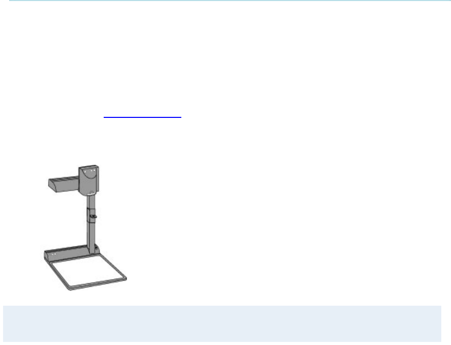
TANDBERG 3000 MXP
220
5.2 Document Camera
A document camera can be used for showing text, diagrams and a variety of graphical material
as well as small three-dimensional objects.
How to use a document camera with your system:
1. Connect the document camera to the Doc Cam input, if available, on the system.
2. Open the Presentation menu from Main menu and choose Doc Cam.
3. You can also program the Presentation key on the remote to activate document camera.
See chapter Presentation Key for more information.
If you want to use S-Video from the document camera, you can connect the document camera to
the AUX input on the system.
Note that this requires a system with an additional video input.
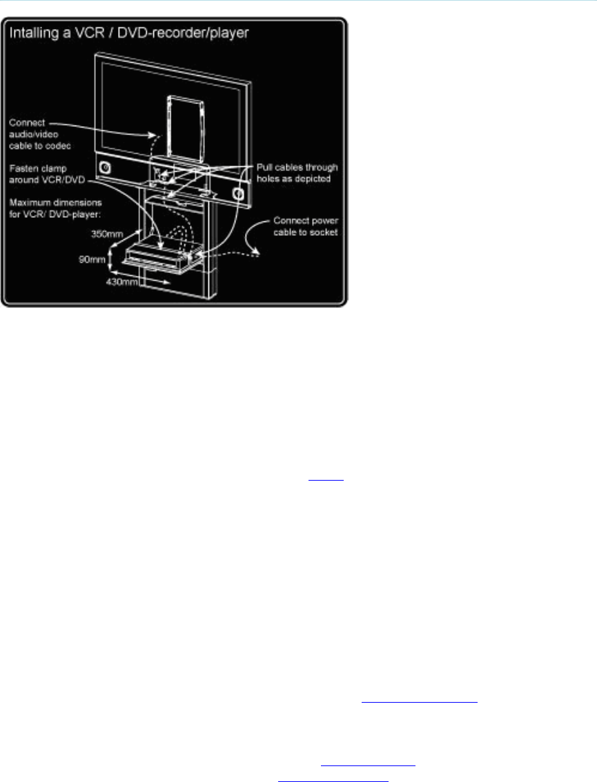
Peripheral Equipment
221
5.3 DVD / VCR
Installing a VCR/DVD-recorder/player
DVD/VCR Playback
Mono
For playback, connect a cable between Video Out on the VCR and Video In (VCR) on the
system. Connect a cable between Audio Out on the VCR and the Audio In (VCR) on the system.
Choose VCR from the Presentation menu to activate the VCR input.
Make sure that Audio In (VCR) is On (see chapter Audio). If audio from VCR is too low, this level
can be adjusted in Audio Settings, Inputs, Level Settings. The audio from the VCR will be audible
in the local speaker system.
The audio from the VCR and your microphone(s) will be mixed and sent to the far end. When a
person talks on either local or far end, the VCR audio level will be reduced to make it easier to
comment on a video recording when Audio Settings, VCR Ducking: On.
Stereo
For stereo playback, connect:
Video cable between Video Out on the VCR and Video In (VCR) on the system
Audio cable between Audio Out (L) on the VCR/DVD and the VCR L (Audio In 3)
Audio cable between Audio Out (R) on the VCR/DVD and VCR R (Audio In 4)
Choose the VCR video source (se chapter Presentation menu) to automatically
activate the VCR audio and video input.
Make sure that:
Stereo Input Mode is set to On (see chapter Stereo Settings)
128 AAC-LD is enabled (see chapter AAC-LD 128 kbps)

TANDBERG 3000 MXP
222
AAC-LD is enabled (see chapter Audio Algorithm)
Audio In (VCR) is On (see chapter Audio). If audio from VCR is too low, this level can be
adjusted in Audio Settings, Inputs, Level Settings. The audio from the VCR will be audible
in the local speaker system.
To enable VCR/DVD ducking (reduce volume when speaking), check that VCR Ducking
under Audio Settings is set to On.
Note that the audio from the VCR/DVD and your microphone(s) will be mixed and sent to the far
end. When a person talks on either local or far end, the VCR/DVD audio level will automatically
be reduced to make it easier to comment on a video recording when Audio Settings, VCR
Ducking: On.
VCR - Recording
When recording, the VCR will record the video as it appears on the main monitor, the local audio
and the audio from the far end.
When recording a videoconference, connect a cable between Video Out 2 on the system and
Video In on the VCR. Connect a cable between Audio Out 2 on the system and Audio In on the
VCR.
Note that a system with one video output and one mixed (local and far end) audio output is
required for recording. For playback, a system with one video input and one audio input
without integrated echo cancellation is required.

Peripheral Equipment
223
5.4 Additional Cameras
Extra fixed Cameras
You can connect extra fixed cameras to your system, for example, a whiteboard camera. Connect
the video output of the additional camera to one of the available Video inputs on the system.
Multiple controllable Cameras
Attaching multiple cameras to one system expands visibility and is useful in large group
applications.
The system is able to control up to 4 WAVE II -cameras. Optional WAVE II cameras are supplied
with the necessary cabling. In addition, an external power supply for the camera is included.
WAVE II -camera number two must be connected to video input 2. Camera number three must be
connected to video input 3, and so forth.
The maximum length of the camera cable for multiple cameras supported by TANDBERG is 20 m
(65 ft).
Note that additional controllable cameras are only available for some rollabout systems.
Settops and personal systems may be able to connect additional cameras.

TANDBERG 3000 MXP
224
5.5 Additional Microphones
If your environment is such that you require more than one microphone for your room, e.g. you
have a whiteboard at a distance from your table microphone, it is possible to connect additional
microphones to your system. See Appendix 4 for more information.
Note that this requires a system with more than one XLR input.
You can connect two microphones to your system. The connectors are marked Mic1, Mic2. The
connected microphones will by default be mixed.
When more than one microphone is connected, you have the option to use the Voice Activate
Camera Tracking feature.
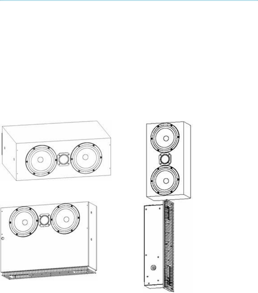
Peripheral Equipment
225
5.6 The TANDBERG DNAM and
Speakers
TANDBERG 6000 MXP Profile, TANDBERG 6000 MXP, TANDBERG 7000
MXP, TANDBERG 8000 MXP and TANDBERG Maestro
The TANDBERG Digital Natural Audio Module, DNAM*:
The DNAM audiosystem is built on two specially designed and separate modules; the DNAM
audio amplifier and the DNAM loudspeaker cabinet. The DNAM loudspeaker cabinet is based on
several editions, one for each of the 6000 MXP, 6000 MXP Profile, 7000 MXP and 8000 MXP
systems. For the 6000 MXP and the 8000 MXP system, the audio amplifier is integrated in the
loudspeaker cabinet. For the Maestro system the amplifier and the loudspeaker cabinet is
integrated directly into the system pedestal.
TANDBERG 6000 MXP DNAM configuration
TANDBERG 8000 MXP DNAM configuration
TANDBERG 7000 MXP DNAM
configuration
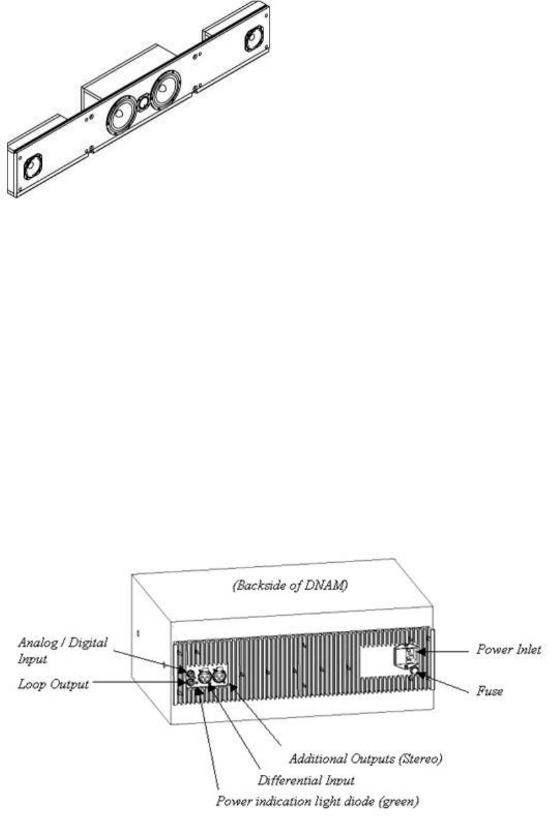
TANDBERG 3000 MXP
226
TANDBERG 6000 MXP Profile DNAM configuration
Center Speakers + Integrated Stereo Speakers
The DNAM Amplifier*:
3 x 50W continuous average Center Output Power (load specified by DNAM Center
Speakers).
2 x 50W continuous average Stereo Output Power (load specified by TANDBERG
Loudspeaker Stereo Kit).
Full dynamic range for audio (high fidelity range)
Digital Signal Processing and Filtering on all channels for best audio detail clarity
Digital Crossover Filtering on center channels.
In/out:
Audio In - S/PDIF (stereo) or Analog (mono), using the same connector.
Differential In - (female XLR pinout: 1 - GND, 2 – Signal (+), 3 – Signal (-))
Loop Out - line out directly from the input, always analog even with S/PDIF in.
Stereo Out - (male XLR, common GND configuration)
Fuse 2A 250V Slow, 5 x 20mm, Littelfuse type 215002.
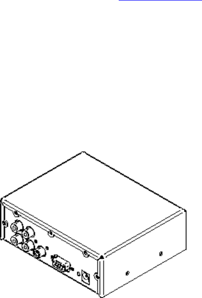
Peripheral Equipment
227
The DNAM Loudspeaker Cabinet (Center Speakers)*:
3-way Center Speaker system
Frequency range 50Hz - 20kHz
2 x 130mm low- and midrange loudspeakers, 8 ohms nominal, high quality
1 x 25mm dome tweeter, 6 ohms nominal, high quality
Crossover filtered audio signals received from DNAM amplifier
Long time max power 90 Watt on all loudspeakers
Enclosed MDF speaker cabinet
Integrated Stereo Speakers**:
2 * 15W Stereo Speakers, high quality
Frequency range 100Hz - 20kHz
Enclosed MDF speaker cabinet
Using the external and optional Stereo Speaker Kit will improve the stereo sound, even on
systems with integrated stereo speakers**. Note that the kit is not available for Mini-DNAM
described below. Before connecting the Stereo Speaker Kit, make sure the complete
videoconferencing system is powered down. When connecting the Stereo Speaker Kit to a
system with already integrated stereo speakers, these integrated speakers will be disabled, and a
new filter and specification setup is loaded when powering up the videoconferencing system.
Please refer to the section Stereo Speaker Kit for details.
TANDBERG 3000 MXP Profile:
The TANDBERG Mini-DNAM*:
The Mini-DNAM audiosystem is built on two specially designed and separate modules; the Mini-
DNAM amplifier and the Mini-DNAM loudspeaker cabinet. The Mini-DNAM loudspeaker cabinet is
stereo-configured and based on two versions made for fitting both the TANDBERG 3000 Profile
43’’ and 32’’ systems. The compact sized amplifier is mounted in the rear of the speaker cabinet.
The Mini-DNAM amplifier*:
The Mini-DNAM amplfier specification:
Stereo digital SPDIF input
2x30W into 8ohm
External DC power supply
Compact size

TANDBERG 3000 MXP
228
The Mini-DNAM Loudspeaker Cabinet*:
The Mini-DNAM speaker cabinet specification:
2 * 15W Stereo Speakers, high
quality
Frequency range 100Hz - 20kHz
Enclosed MDF speaker cabinet
Integrated Stereo Speakers**:
2 * 15W Stereo Speakers, high quality
Frequency range 100Hz - 20kHz
Enclosed MDF speaker cabinet
*Note that there are different solutions on integrated audio modules and speakers included in the larger high-end
TANDBERG systems. Please contact your TANDBERG representative for more information.
** These are available with the TANDBERG 3000 MXP Profile and TANDBERG 6000 MXP Profile only.

Peripheral Equipment
229
5.7 Stereo Speaker Kit
Note that the following applies only for systems with a stereo S/PDIF output.
The Stereo Speaker Kit provides an pair of floor-standing loudspeakers in addition to the built-in
DNAM. Using these speakers will enable stereo functionality in your system and thereby enhance
the sound experience.
To experience stereo sound, the stereo speakers have to be connected to the Digital Natural
Audio Module (DNAM) as well as confirming this under Stereo Settings in the main audio menu.
The stereo sound source may either be located at the far end, or locally as a sound source (CD,
DVD) connected to the codec audio AUX/VCR inputs. If using a local stereo sound source, you
also have to enable Stereo I/O mode (On) in the same audio menu, to be able to receive stereo
sound on your system, and to send stereo signals to the far end. See chapter 4.5.4 for more
information.
Check also that the full-range frequency audio coding AAC-LD is enabled (In Call Quality menu,
AAC-LD is checked, and AAC-LD 128 threshold is the same or lower than the call rate you are
planning to use). See chapter Audio Algorithm and AAC-LD 128kbps for more information.
An installation sheet is enclosed in the Stereo Loudspeaker Kit, which also describes
recommended physical speaker placement. Make sure the complete videoconferencing system is
powered down before connecting the Stereo Speaker Kit.
Note that if stereo speakers are enabled in the menu without having any stereo speakers
connected to the Digital NAM, or having other speakers than the TANDBERG stereo
speakers, it may cause the acoustic echo-canceller to malfunction.
Stereo Speaker Kit specification:
2-way Stereo Speaker system (dual speakers in low- and midrange)
Passive Crossover Filtering.
Frequency range 50Hz - 20kHz
2 x 130mm low- and midrange loudspeakers, 8 ohms nominal, high quality.
1 x 25mm dome tweeter, 6 ohms nominal, high quality
Long time max power 90 Watt on all loudspeakers
Enclosed aluminium speaker cabinet
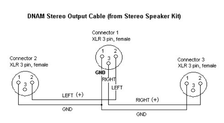
TANDBERG 3000 MXP
230

Peripheral Equipment
231
5.8 Telephone Add-On
The system has a built in audio bridge* that can bring in Voice over IP (VoIP) telephony or normal
telephone sites using ISDN.
Note that this requires a system with mixed audio output (audio from local and far end) and
one audio input without integrated echo cancelling.
In addition to using ISDN and IP for your telephone sites, it is possible to connect a telephone
using normal POTS line** by
Connect the audio out from the conference telephone to the AUX input.
Connect the audio input from the conference telephone to the AUX output, which
provides a mixed signal between local and far end.
*optional MultiSite package available
** require a conference phone with external audio input and output

TANDBERG 3000 MXP
232
5.9 Dual Monitor
Note that this requires a system with dual monitor video output.
It is possible to install the system in a Dual Monitor configuration. The Dual Monitor can be used
to show full screen selfview, still images and Duo Video.
To use the system in the Dual Monitor configuration:
1. Connect "Video Out 3" (composite video output) on the system to a video input on the
dual monitor.
2. Set "Dual Monitor: On" in General Settings menu.
Alternatively you can use a PC monitor as your second monitor:
1. Connect "DVI-I out" on the system to your PC monitor.

Peripheral Equipment
233
5.10 XGA Monitors and Projectors
(Optional)
Some TANDBERG systems can be delivered with optional single or dual TV/XGA monitors. It can
also be connected to any DVI/VGA/PAL or NTSC display.
Note that this requires a system with minimum one DVI-I output.

TANDBERG 3000 MXP
234
5.11 VESA Display Power
Management
Because of the tremendous amount of energy consumed by monitors when operating, the system
will reduce power consumption and extend monitor lifecycle by suspending the (switch off)
monitors and projectors when the system goes into sleep/standby.
This applies for all VESA Display Power Management compliant displays that are connected to
the VGA/DVI output of the system. The display device need to comply with VESA display Power
Management system (DPMS).
Note that this requires a system supplied with a VGA/DVI output.
The VESA DPMS standard consists of four modes, Normal, Standby, Suspend and Off, and
applies to all Sync formats (e.g. VGA).
DPMS standard:
Normal Standby Suspend Off
H-sync On Off On Off
V-sync On On Off Off
Power savings None Minimal Substantial Maximum
Recovery time None 2-3 seconds 2-3 seconds 8-10 seconds
In Off mode some power may still be drawn in order to power indicator lights etc. EDID contains
the information on which mode a specific monitor supports.
TANDBERG supports all four modes. However, in F1 and above, all monitors not listed below are
automatically set to Off.
Monitor DPMS mode
Dell Off
T8000 - Pioneer Suspend
T6000 - SAMPO Suspend
Maestro - Projection Design Off
T7000 - Sharp Off

Peripheral Equipment
235
5.12 Digital Monitor Power
Management
DMPM is monitor power management applied over the digital DVI interface. TANDBERG
supports DMPM in software F2 and above. Six monitor power states are defined.
Monitor On Power state
Transmitter (TANDBERG codec) and receiver (Monitor) are powered and active. This power state
is equivalent with the DPMS normal mode.
Intermediate Power state
When the codec goes from active to standby, it turns off the DVI transmitter and the monitor can
go from Monitor On
Power state to Intermediate Power state
Active-off Power state
The monitor can go from Intermediate Power state to Active-off Power state when the monitor
timer expires.
Non-Link Recoverable Off Power State
The monitor can enter Non-Link Recoverable Off Power State when the codec is switched off or if
the DVI cable is disconnected. This power state is equivalent to the DPMS “Off (with no DPMS
recovery)” state.
Monitor Power Switch Off Power state
This state can be entered when the power switch on the monitor is toggled to its off position. This
state has two sub-states dependent on if the codec is switched on or off.

TANDBERG 3000 MXP
236
5.13 Extended Display Identification
Data (EDID)
Extended Display Identification Data (EDID) is a VESA standard data format that will allow the
system to communicate its capabilities, including vendor information like the supported VGA-
formats and frequency range limits to a PC connected to the XGA/DVI input.
Note that this requires a system supplied with a XGA/DVI input.
This means that the PC always* will be able to output a valid VGA/DVI signal to the system with
no manual reconfiguration of the PC screen settings.
TANDBERG supports EDID structure v1.3, which adheres to the MS Plug & Play definition.
This standard contains information on product ID, basic display parameters, timing identifications
and detailed timing descriptions.
In F1 and above, TANDBERG will use the EDID information to decide which resolution to use,
800x600 @ 75Hz or 1024x768 @ 60Hz.
Example (1024x768@60Hz)
Detailed timing description:
PixelClockDiv10000: 6500
Horizontal Active: 1024
Horizontal Blanking: 320
Vertical Active: 768
Vertical Blanking: 38
Horizontal Sync
Offset: 24
Horizontal Sync Pulse
Width: 136
Vertical Sync Offset: 3
Vertical Sync Pulse
Width: 6
Horizontal Image
Size: Not available
Vertical Image Size: Not available
Horizontal Border: 0
Vertical Border: 0

Peripheral Equipment
237
Tested and verified monitors, EDID & Timing
Listed below are some of the monitors TANDBERG have tested and verified against:
ADI A715
Dell W1700
EIZO L367
EIZO F730
ErgoScan 400S
Hitachi CM640ET
Hitachi CM769ET
IBM 9494-HBO
IBM G97
IBM E74
IBM 6743-60N
JVC LT-23X475
LG L3200A
Löewe TAA112747
MAG D700
MAG DJ707
Panasonic SL75
Pioneer PDP-43MXE1
Pioneer PDP-502MXE
Pioneer PDP-50MXE1
Samsung 191T
Samsung 323T
*Need to comply with the VESA EDID standard.

238
6 Appendices
Appendices:
Appendix 1: Technical Specification
Appendix 2: Bandwidth Information
Appendix 3: Environmental considerations
Appendix 4: Guidelines for setting up videoconferencing rooms
Appendix 5: Security
Appendix 6: Using the file system
Appendix 7: Web Interface
Appendix 8: Connecting the system to PRI/T1
Appendix 9: Connecting the system to the Switched 56 network
Appendix 10: Connecting the system to ISDN using NT1 network adapters
Appendix 11: Wave II Camera Pinouts and Connectors
Appendix 12: Remote control
Appendix 13: CallManager registration
Appendix 14: Diagnostic Tools for IP
Appendix 15: System Upgrade
Appendix 16: Declaration of Conformity
Appendix 17: Dimensions
Appendix 18: How to remove the codec

Appendices
239
6.1 Appendix 1
Technical Specification
SYSTEM COMPONENTS
1 or 2 monitors, wireless remote control, W.A.V.E. II
camera, microphone, integrated cabling, rollabout stand
MONITOR
LG 32" NTSC/PAL flat screen and Pioneer 43” flat
screen
XGA monitor optional
Other monitors supported
BANDWIDTH
H.320 up to 512 kbps
H.323 up to 2 Mbps
SIP up to 2 Mbps
FIREWALL TRAVERSAL
TANDBERG Expressway TechnologyTM
Auto NAT
VIDEO STANDARDS
H.261, H.263, H.263+, H.263++ (Natural Video), H.264
VIDEO FEATURES
Native 16:9 Widescreen
Advanced Screen Layouts
Picture in Picture (PIP)
Picture outside Picture (POP)
Side by Side
PC Zoom
Intelligent Video Management
Simultaneous videoconference & local PC mode
VIDEO INPUTS (5 INPUTS)
1 x 9 Pin DSUB: S-video & control main camera
1 x MiniDin, S-video: auxiliary / document camera
1 x RCA / Phono, composite: document camera / aux
1 x RCA / Phono, composite: VCR
1 x DVI/SXGA: PC
Input: 800 x 600 (@ 60, 72, 75, 85 Hz), 1024 x 768
(@ 60, 70, 75 Hz), 1280 x 1024 @ 60 Hz
Extended Display Identification Data (EDID)
VIDEO OUTPUTS (4 OUTPUTS)
1 x MiniDin, S-video: main monitor
1 x RCA / Phono, composite: main monitor or VCR
1 x RCA / Phono, composite: dual monitor or VCR
1 x DVI/XGA: main or second monitor
XGA Output
800 x 600 @ 75 Hz, 1024 x 768 @ 60 Hz,
1280 x 768 (WXGA) @ 60 Hz
VESA Monitor Power Management
VIDEO FORMAT
NTSC, PAL, VGA, SVGA, XGA, W-XGA or SXGA
IP NETWORK FEATURES
H.235 Authentication
Differentiated Services (DiffServ)
Resource Reservation Protocol (RSVP)
IP precedence
IP type of service (ToS)
IP adaptive bandwidth management (including flow
control)
Auto gatekeeper discovery
Dynamic playout and lip-sync buffering
Intelligent Packet Loss Recovery (IPLR)
H.245 DTMF tones in H.323
Cisco Call Manager integration using ECS
IP Address Conflict Warning
SECURITY FEATURES
Management via HTTPS
IP Administration Password
Menu Administration Password
Dialing Access code
Streaming password
H243 MCU Password
VNC password
SNMP security alerts
Disable IP services
MD-5 Challenge
Network Settings protection
SIP Authentication via NTLM and Digest Authentication
IEEE 802.1x
NETWORK INTERFACES
4 x ISDN BRI (RJ-45), S-inter face
1 x LAN / Ethernet (RJ-45) 10/100 Mbit (LAN / DSL /
cable modem)
1 x X.21 / V.35 / RS-449 with RS-366 dialing, Leased
Line
or data triggered mode**
1 x PC card slot (PCMCIA) for wireless LAN
1 x USB (for future use)
WIRELESS LAN SUPPORT
Compliant with IEEE 802.11b, up to 11 Mbit
Support for 64 / 128 bit encryption (WEP)
Infrastructure or ad-hoc mode
ETHERNET / INTERNET / INTRANET CONNECTIVITY
TCP / IP, DHCP, ARP, FTP, Telnet, HTTP, HTTPS,
SOAP and XML
SNMP Enterprise Management
Internal web server
Internal streaming server
OTHER MAJOR ITU STANDARDS SUPPORTED
H.231, H.233, H.234, H.235 v2&v3, H.239, H.241,
H.243,

TANDBERG 3000 MXP
240
LIVE VIDEO RESOLUTIONS
NATIVE NTSC:
4SIF (704 x 480 pixels), Digital Clarity
Interlaced SIF (352 x 480 pixels), Natural Video
SIF (352 x 240 pixels)
NATIVE PAL:
4CIF (704 x 576 pixels), Digital Clarity
Interlaced CIF (352 x 576 pixels), Natural Video
CIF (352 x 288 pixels)
QCIF (176 x 144 pixels)
SQCIF (128 x 96 pixels) decode only
NATIVE PC RESOLUTIONS:
XGA (1024 x 768)
SVGA (800 x 600 pixels)
VGA (640 x 480 pixels)
STILL IMAGE TRANSFER
CIF, SIF, 4CIF (H.261 Annex D), 4SIF, VGA, SVGA,
XGA
AUDIO STANDARDS
G.711, G.722, G.722.1, G.728, 64 bit & 128 bit MPEG4
AAC-LD
AUDIO FEATURES
CD-Quality 20 KHz Mono and Stereo
Telephone add-on via MultiSite
Two separate acoustic echo cancellers
Audio mixer
Automatic Gain Control (AGC)
Automatic Noise Reduction
Audio level meters
VCR ducking
Packet loss management
Active lip synchronization
GSM / Blackberry noise filter
AUDIO INPUTS (4 INPUTS)
2 x microphone, 24V phantom powered, XLR connector
1 x RCA / Phono, Line Level: auxiliary (or VCR Stereo L)
(Audio input 3: Switchable mic or line level)
1 x RCA / Phono, Line Level: VCR/DVD (Stereo R)
AUDIO OUTPUTS (2 OUTPUTS)
1 x RCA / Phono, S/PDIF (mono/stereo) or Analogue
Line
Level: main audio or Analogue Stereo L
1 x RCA / Phono, Line Level: VCR or Analogue Stereo R
FRAME RATES
30 frames per second @ 168 kbps and above
60 fields per second @ 336 kbps and above (Point-to-
point)
DUAL STREAM
Duo Video & H.239
Available on H.323 & H.320
Available in MultiSite from any site
NETWORK FEATURES
Auto H.320 / H.323 dialing
SIP
Downspeeding
Programmable network profiles
Intelligent Call Management
Maximum call length timer
Automatic SPID and line number configuration
(National ISDN, GR-2941-CORE)
SoftMux
H.281, BONDING (ISO 13871), H.320, H.323, H.331
RFC 3261, RFC 2237, RFC 3264, RC 3311, RFC 3550,
RFC 2032, RFC 2190, RFC 2429, RFC 3407, H.460.18,
H.460.19
W.A.V.E. (WIDE ANGLE VIEW) II CAMERA
10 x zoom 1/4" CCD +15° / -20° tilt + / -95°pan
61° vertical field of view
96° total vertical field of view
77° horizontal field of view
267° total horizontal field of view
460 (PAL) / 470 (NTSC) TV lines
Min. illumination 2 Lux (F1.8)
Auto or manual focus / brightness / white balance
Far-end camera control
15 near and far-end camera pre-sets
Voice-activated camera positioning
Daisy chain support for up to 4 cameras
PRESENTATIONS AND COLLABORATION
Natural Presenter Package including:
PC Presenter
PC SoftPresenter
Digital Clarity
DuoVideo and H.239
Advanced Video Layouts
Streaming compatible with Cisco IP/TV,
Apple QuickTime®, RealPlayer® v8 etc.
CLOSED CAPTIONING/TEXT CHAT
T.140 text chat available from RS-232, Telnet,
Web and User Inter face
PRESENTATIONS AND COLLABORATION
Natural Presenter Package including:
PC Presenter (DVI-I, SXGA In)
PC SoftPresenter
Digital Clarity & Native Formats
Advanced Video Layouts
Streaming compatible with Cisco IP/TV,
Apple QuickTime®, RealPlayer® v8 etc.
SYSTEM MANAGEMENT
Support for the TANDBERG Management Suite
Total management via embedded web server, SNMP,
Telnet, FTP and SOAP
Remote software upload :via web server or FTP server
1 x RS-232 local control and diagnostics
Remote control and on-screen menu system
DIRECTORY SERVICES
Support for Local, Global and Dynamic Server
Directories
Unlimited entries using Server directory* supporting
LDAP and H.350
400 number global directory
200 number local directory
50 dedicated MultiSite entries
Last Number Dialed, Missed Calls, Call History
Directories in Local Languages
16 SELECTABLE MENU LANGUAGES
English, German, French, Norwegian, Swedish, Italian,
Spanish, Portuguese, Simplified Chinese, Traditional
Chinese, Japanese, Russian, Korean, Finnish, Thai and
Arabic

Appendices
241
H.331 Broadcast Mode
NATO standard KG194 / KIV-7 encryptor support**
URI Dialing
IP version 6
MULTISITE FEATURES
H.323/H.320/SIP/Telephony/VoIP in the same
conference
Audio and Video Transcoding
Video rate matching from 56 kbps - maximum
conference rate
CP4 and Voice Switched
Best Impression (Automatic CP Layouts)
H.264, Encryption, Digital Clarity
Dual Stream from any site
ISDN & IP Downspeeding and IPLR
MultiSite (H.243) Cascading on H.320 & H.323
Dial in / Dial out
Chair control for host system
Snapshot of ongoing conference (JPEG)
Snapshot of ongoing DuoVideo/H.239 presentation
(JPEG)
Separate welcome page for enrypted conferences
Conference rates up to 2.3 Mbps with optional
bandwidth
upgrade (1.5 Mbps is standard conference rate)
Up to 4 video and 3 audio sites
4 sites @ 768 kbps (+telephone calls)
Mix ISDN-BRI and IP up to maximum conference rate
EMBEDDED ENCRYPTION
H.320 and H.323 point-to-point and multipoint calls
Standards-based: H.233, H.234, H.235 v2&v3, DES and
AES
NIST-validated AES
NIST-validated DES
Automatic key generation and exchange
Supported in Dual Stream and Multisite
CUSTOMIZED WELCOME SCREEN AND COMPANY
LOGO
POWER
100 - 250 VAC, 50 - 60 Hz 65 watts max. for codec and
main camera 500 watts max. per monitor
OPERATING TEMPERATURE AND HUMIDITY
0° C to 35° C (32° F to 95° F) ambient temperature.
10% to 90 % Relative Humidity (RH)
STORAGE AND TRANSPORT TEMPERATURE
-20° C to 60° C (-4° F to 140° F) at RH 10-90 % (non-
condensing)
APPROVALS
Directive 73/23/EEC (Low Voltage Directive)
-Standard EN 60950
Directive 89/336/EEC (EMC Directive)
-Standard EN 55022, Class B
-Standard EN 55024
-Standard EN 61000-3-2/-3-3
Directive 1999/5/EEC (R&TTE Directive)
-Standard TBR3
Approved according to UL 60950
and CAN/CSA C22.2 No. 60950
Complies with FCC15B Class B
FOOTPRINT
Width: 36.2" / 91.9 cm
Depth: 31.3" / 79,4 cm
Hight: 0.35” / 9 cm
PRODUCT RELIABILITY / MTBF
The predicted reliability is expressed in the expected random Mean Time Between Failures (MTBF) for the electronic
components based on the Power On Hours:
Power On Hours (POH) > 69 000 hours
Useful Life Cycle > 6 years
ISO 9001 certificate is available upon request
* Requires TANDBERG Management Suite 9.0 or newer
** Optional equipment, must be specified at the time of order.
System features vary depending on network selection and software package. All specifications subject to change without
notice. TANDBERG is a registered trademark or trademark of TANDBERG in the U.S. and other countries. RealPlayer is
a trademark or a registered trademark of RealNetworks, Inc. QuickTime is a registered trademark of Apple Computer,
Inc., registered in the U.S. and other countries. Microsoft and NetMeeting are either registered trademarks or trademarks
of Microsoft Corporation in the United States and/or other countries. All other trademarks are property of their respective
owners. Contains iTypeTM from Agfa Monotype Corporation
Service availability may vary from region to region. Please contact your TANDBERG reseller for more information.

TANDBERG 3000 MXP
242
6.2 Appendix 2
Bandwidth information for TANDBERG endpoints
Model 8000MXP, 7000MXP 6000MXP, Maestro
Bandwidth
Point to
point
ISDN / IP
Standard: 768 / 3072
Option: 1920 / 4096 Standard: 768 / 3072
Option: 1920 / 4096
MultiSite Total: 3072kbps 4x768
video + 4 audio 3x1536
video + no audio
Total: 6144kbps 6x1152
video + 5 audio 5x1536
video + no audio
4x1920
video + 5 audio 3x3072
video + no audio
Total: 3072kbps 4x768
video + 4 audio 3x1536
video + no audio
Total: 6144kbps
6x1152
video + 5 audio 5x1536
video + no audio
4x1920
video + 5 audio 3x3072
video + no audio
Rate
Matching Yes Yes
Dual
Stream
(DuoVideo
/ H.239)
Yes Yes
Secure
Conference
All bandwidths All bandwidths
H.264 Up to 2Mbps Up to 2Mbps
Picture
Mode
MultiSite
VS, CP4, CP5+1 VS, CP4, CP5+1

Appendices
243
Model 3000MXP / 3000NET
MXP 2000MXP, 1500MXP
Bandwidth
Point to
point
ISDN / IP
Standard: 384 / 1536
Option: 512 / 1920
3000NET: 384 / 1536
Standard: 1920 (IP only)
Options: 512 / 1920
MultiSite Total: 1536kbps
4x512 video + no
audio
4x384 video + 3 audio
Total: 2304kbps
4x768
video + no audio
4x512
video + 3 audio
Total: 2304kbps 4x768
video + no audio 4x512
video + 3 audio
Rate
Matching Yes
Yes
Dual
Stream
(DuoVideo
/ H.239)
Yes
Yes
Secure
Conference
All bandwidths
All bandwidths
H.264 Up to 2Mbps Up to 2Mbps
Picture
Mode
MultiSite
VS, CP4, CP5+1 VS, CP4, CP5+1
Model 990MXP / 990NET
MXP 880MXP / 880NET MXP
Bandwidth
Point to
point
ISDN / IP
Standard: 1920 (IP
only)
Options: 512 / 1920
990NET: 768 / 1920
Standard: 1152 (IP only)
Option: 384 / 1152
MultiSite Total: 2304kbps
4x768
video + no audio
4x512
video + 3 audio
Total: 1152kbps 4x384
video + no audio 4x320
video + 3 audio
Rate
Matching Yes Yes
Dual
Stream
(DuoVideo
/ H.239)
Yes Yes
Secure
Conference
All bandwidths All bandwidths
H.264 Up to 2Mbps Up to 768

TANDBERG 3000 MXP
244
Picture
Mode
MultiSite
VS, CP4, CP5+1 VS, CP4, CP5+1
Model 770MXP 1000MXP
Bandwidth
Point to
point
ISDN / IP
Standard: 768 (IP
only)
Option: 128 / 768
Standard: 768 (IP only)
Options: 128 / 768, 384
/ 768
MultiSite Not Available Not Available
Rate
Matching Not Available Not Available
Dual
Stream
(DuoVideo
/ H.239)
Yes Yes
Secure
Conference
All bandwidths
All bandwidths
H.264 Up to 768 Up to 768
Picture
Mode
MultiSite
Not Available Not Available
Model 550MXP
Bandwidth
Point to
point
ISDN / IP
Standard: 768 (IP only)
Options: 128 / 768, 384
/ 768
MultiSite Not Available
Rate
Matching Not Available
Dual
Stream
(DuoVideo
/ H.239)
Not Available
Secure
Conference
All bandwidths
H.264 Up to 768
Picture
Mode
MultiSite
Not Available

Appendices
245
6.3 Appendix 3
Environmental considerations
This section explains how to carry out basic adjustments and simple tests to ensure that you send
and receive the best possible image and audio quality when using your system.
Iris control and lighting
By default the system camera will use an automatic iris to compensate for changes in lighting. In
addition to this feature, you may further assist the system to maintain the best possible image
quality by paying special attention to environmental lighting and background colors as described
below. Remember the system will send live images of yourself and your immediate surroundings.
Avoid direct sunlight on the subject matter i.e. yourself, the background or onto the
camera lens as this will create harsh contrasts.
If light levels are too low you may need to consider using artificial lighting. As described
above, direct illumination of the subject matter and camera lens should be avoided.
When using artificial lighting, daylight type lamps will produce the most effective results.
Avoid colored lighting.
Indirect light from shaded sources or reflected light from pale walls often produces
excellent results.
Avoid harsh side lighting or strong light from above. Strong sunlight from a window or
skylight may put part or all of the subject matter in shadow or cause silhouetting.
If you still have problems with the iris and lighting, manual adjustment of the camera
parameters might help – see Video Settings menu.
Dim scenes can also be improved by manually adjusting the camera brightness setting.
Background
The appearance of the picture background is very important but easily overlooked. It is important
to remember that the camera also shows what is behind you when in a videoconference. To
ensure a suitable background we recommend you consider the following:
Use a neutrally colored background with a medium contrast and a soft texture, e.g. a
plain curtain with no heavy patterns or strong colors that may adversely tint the whole
scene.
Avoid moving backgrounds such as curtains blowing in a draught, moving objects, or
people walking behind as this may both reduce image quality and distract the attention of
the calling party.
Do not place the camera facing a doorway.
Loudspeaker volume
The audio system will use the Digital Natural Audio Module (DNAM) if available and supported by
the system. The volume of the audio system is controlled by the Volume Control keys on the
system remote control.

TANDBERG 3000 MXP
246
6.4 Appendix 4
Guidelines for setting up videoconferencing rooms
The following are a set of guidelines to consider when either building a videoconferencing room,
or using an existing room for videoconferencing.
Lighting:
Low Contrast desired for light
intensity. No dark spots.
Intensity @ table 800 - 1400 Lux as
measured with an Incident light
meter.
Block sunlight from entering room.
Seating Area (Table):
Should allow all participants to see
Monitors.
Should allow camera to “see” all
participants.
Non-shiny non-patterned preferably
light grey surface (if table used).
Walls:
Color: Generally high contrast color
desired. Light blue is commonly
used.
Acoustically reflective surfaces (such
as glass or concrete) should be
covered with curtains or sound
treatment.
Audio:
Noise Floor preferred less than
44dBC.
Reverb Time 0,3 to 0,5 sec.
Ventilation:
Keep in mind Noise Floor.
Velocity = Noise. Therefore keep
velocity of air low.
Room:
Should be located away from noise.
Should not have windows.
Doors should be located off camera.
How to prepare a typical room for videoconferencing:
The illustration below shows the principles of a typical room designed to obtain the best results
when using a videoconference system.
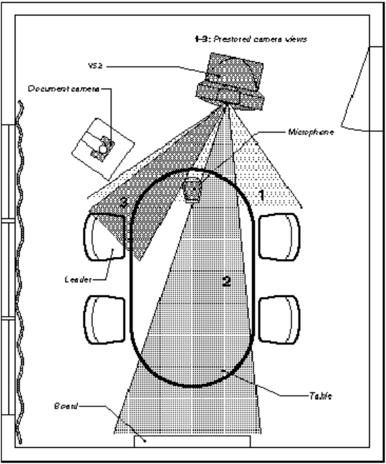
Appendices
247
If the system has a separate microphone, it should be placed at the front of the table to ensure
that all speech will be detected. The best position for the microphone is at least 2 meters (6.5
feet) in front of the system on a plain, flat table with at least 0.3 meters (12 inches) of table in front
of the microphone.
The document camera should be close to the chair person or a designated controller of the
document camera for ease of use (remember to arrange all the peripherals so that one participant
can reach each of them to point, change the display, tape, and so forth).
The camera supports up to 15 pre-stored camera positions.
The illustration shows three possible camera positions; one for all the participants, one for the
whiteboard and one for the main speaker. The remaining camera presets are then available for
other peripheral equipment, for example a VCR.
Position the system in such a way as to avoid the possibility of somebody inadvertently walking
into the camera’s field of view when entering the room. Other than the conference participants,
there should be no moving items in the sent image.

TANDBERG 3000 MXP
248
6.5 Appendix 5
Security
The system has several features both to protect from unauthorized use and system access:
Access Code:
When Access Code is enabled, the user will be asked to enter an access code before he/she is
able to make a call. The system will verify if the entered access code is valid by checking the
code with the allowed codes listed in the access.txt file on the ftp-server in the system. If no
access.txt file is uploaded to the system, registration of the code will be done without validation.
E.g. you can enter whatever code you want and have access to the system.
The access.txt file is a plain text file with one line per access code as shown below:
1234
1250
A1
B2
ABC
To upload this file to the system, follow these steps:
Open a DOS-window and go to the folder where the ‘access.txt’ file is located.
Type ftp <IP-address of your local system).
User: press Enter or enter IP-password.
Type “bin” and press Enter.
Go to the user folder, type “cd user”.
Upload the ‘access.txt’ file, type ‘put access.txt’.
Exit from ftp, type "bye".
Administrator Password
Access to the administrator menu on the system unit can be controlled using password
protection. You can set the Administrator Password in Menu Settings, in Security or from the
dataport:
menupassword set <pin-code>. The pin-code should be maximum 5 - five digits. To erase the
password, enter an empty pin-code.
Streaming password
By setting a streaming password in the streaming menu on the system, a password has to be
entered on the streaming client to be able to see the video stream from the system.
IP Password
Appendices
249
By setting an IP Access Password on the system, all access to the system using IP (Telnet, FTP
and WEB) requires a password. This password can be enabled from telnet or dataport using the
command: ippassword <ip-password>. The default IP username and password is "TANDBERG".
To remove this password, use the command: "ippassword ”. From telnet, this is only possible by
first entering the correct password.
IP Services
The different IP services on the system - FTP, Telnet, Telnet Challenge, HTTP, HTTPS, SNMP
and H.323 can be disabled to prevent access to the system. By using the commands below, the
services can be independently enabled/disabled:
xconfiguration Telnet/TelnetChallenge/FTP/HTTP/HTTPS/H323 Mode: <On/Off>
xconfiguration TelnetChallenge Mode: <On/Off> [port]
xconfiguration SNMP Mode: <On/Off/ReadOnly/TrapsOnly>
SNMP Security alert
This function will notify any Management Application (such as TMS - TANDBERG Management
Suite) if anyone tries to perform Remote Management on the system using an illegal password.
The Security alert that is sent to the Management Application will contain information about the IP
address and the service (WEB, Telnet, FTP) being used for the attempt. If TMS is used, email
notifications or alarms about the attempt can be sent to specified persons.
Encryption
All TANDBERG systems support both AES and DES encryption. By default this feature is
enabled such that when connecting with any other video system or MCU, a TANDBERG system
will attempt to establish a secure conference using AES or DES encryption. The TANDBERG
system will attempt this for both IP and ISDN connections. Where a remote system or MCU
supports encryption, the highest common encryption algorithm will be selected on a port-by-port
basis.
The type and status of the encryption negotiated is indicated by padlock symbols and on-screen
messages. Encryption on the TANDBERG systems is fully automatic, and provides clear security
status indicators;
An open padlock indicates that encryption is being initialized, but the conference is not
yet encrypted.
Single padlock indicates DES encryption.
Double padlock indicates AES encryption.
In addition to on-screen indicators the Call Status menu provides two information fields regarding
call encryption. The first field is the Encryption Code, which will identify either AES or DES. The
second field is the Encryption Check Code and is comprised of an alphanumeric string. This
string will be the same for systems on either side of an encrypted conference. If the Check Codes
do not match, this would indicate that the call has been exposed to a Man In The Middle attack.
When a system with MultiSite functionality hosts a conference, the highest possible encryption
algorithm will be negotiated on a site-by-site basis. MultiSite conferences can therefore support a
mix of AES and DES encrypted endpoints in the same conference. A conference will only be as
secure as its weakest link.
All systems supporting DES encryption can upgrade to AES encryption. Please contact your
TANDBERG representative for more information. The standards supporting the encryption
mechanisms employed by TANDBERG are: AES, DES, H.233, H234 and H.235 (H235v3 & v2 for

TANDBERG 3000 MXP
250
backwards compatibility) with extended Diffie Hellman key distribution via H.320, H.323 and
Leased Line connections.
The TANDBERG AES implementation is validated as conforming to the Advanced Encryption
Standard (AES) Algorithm, as specified in Federal Information Processing Standard Publication
197, Advanced Encryption Standard, by The National Institute of Standards and Technology
(NIST).
IEEE 802.1x / EAP (Extensible Authentication Protocol)
This is a standard for authentication and authorization of units/systems onto the network.
Static configuration
System ID and Password
Anonymous ID for encryption challenge
Enable methods
Supported methods
MD5 (simple challenge)
PEAP (encrypted channel)
TTLS
Note that 802.1x wireless LAN is not supported.

Appendices
251
6.6 Appendix 6
Using the file system
It is possible to access a file system within the TANDBERG system by using ftp:
DOS-
window: ftp <IP-address of system>, or
Web-
browser: ftp:// <IP-address of system>
Description of the different files:
all.prm all settings in the system (including directory)
dir.prm directory entries (up to 200 entries)
event.log logs fault situations etc.
sw.pkg the system software
globdir.prm file containing up to 400 entries. These entries can not be edited from the
system, but can be edited as a text-file.
Files accessible only by ‘ftp get /tmp/snapshots/xxx.jpg’ or ‘http://<IP-address of
system>/tmp/snapshots/xxx.jpg’:
site0.jpg Snapshot of current stream if MultiSite.
main.jpg Snapshot of selfview.
site1.jpg Snapshot of decoded stream if point-to-point.
duo.jpg Snapshot of the encoded stream if transmitting DuoVideo, the decoded stream if
receiving DuoVideo.
Custom logos
Go to the folder where your logo is located.
Type “ftp <IP-address of your local system>”.
Go to the user folder, type “cd user”.
Upload the logo, type "put <logo.jpg>".
The new logo will be displayed the next time you restart your system. Recommended maximum
size is: 704x576, file-format: jpg. If the file is too large, no logo will be displayed.

TANDBERG 3000 MXP
252
6.7 Appendix 7
Web Interface
It is possible to access and maintain the system remotely via a local area network (LAN) using a
standard Web-browser. Connect your system to a LAN with a Network cable.
How to configure your system for web interface:
1. Open Administrator Settings and choose Network\LAN Settings
2. Specify IP-assignment DHCP or Static. If DHCP is selected, no other settings are
needed. If Static is selected, IP-address, IP-subnet mask and Gateway must be
specified.
3. Start your Web-browser. In the address field type the IP-address of the system. Enter the
password and the Web-page of the system will be shown. The default password is
TANDBERG.
4. Restart the system. Choose Restart from the Control Panel.
Example:
IP-assignment: Static
IP-address: 196.9.200.129
IP-subnet mask: 255.255.255.0
Gateway: 196.9.200.21

Appendices
253
6.8 Appendix 8
(Not available on all TANDBERG systems)
Connecting the system to PRI/T1
Using CSU adapter
Connecting the system to the ISDN network via the E1/T1-interface using an Adtran T1 ESF CSU
ACE or equivalent CSU, will allow up to 1.54 Mbps connection. The E1/T1-interface must be
connected to a CSU approved according to IEC 60950, UL 1950 or equivalent standard. The PRI-
line will run the AT&T 4ESS, 5ESS and National ISDN protocols in addition to Euro ISDN (E1).
Connecting to Adtran T1 ESF CSU ACE
Connect the PRI cable from the system to the input marked CPE (Customer Provided Equipment)
on the Adtran CSU (straight through category 5 cable is recommended). Connect to the network
via the NET connector on the Adtran CSU.
Configuration of the system
Open the Administrator Settings Menu from the Control Panel and select Network.
Choose Network Type: PRI and specify your PRI number, max. Channels, cable length (between
system and CSU) and switch type.
Configuration of Adtran T1 ESF CSU ACE
Enter 2)CONFIG menu using SCROLL and ENTER buttons.
Enter 3)TERMINAL menu. Check 1)FORMAT:ESF, 2)CODE: B8ZS , 3)SET LBO: 0-133
(corresponding to Cable Length setting on the system).
Go to main menu and enter 1)NETWORK menu. 7)SET LBO: 0.0 (according to
information from Telco).
Also, other network parameters should be set according to information from your Telco.
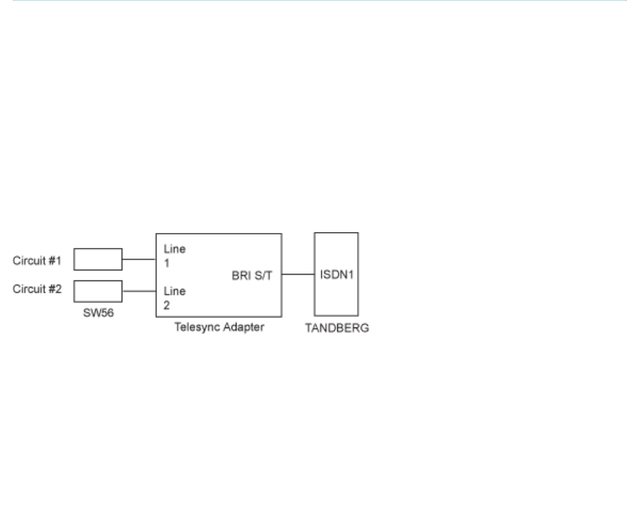
TANDBERG 3000 MXP
254
6.9 Appendix 9
Connecting the system to the Switched 56 network
Using Telesync TS-256 SW56/ISDN adapter
Connecting the system to the SW56 network using a Telesync Adapter is described below. There
are different Telesync Adapters for different configurations of SW56 networks. The network types
tested with the system are SW56 2Wire and 4Wire.
Connecting
Connect the system ISDN1 cable to the BRI S/T interface on the Telesync Adapter. Connect the
two SW56 cables from the Telesync adapter Line 1 and Line 2 to the SW56 network.
Configuration of the system
Select network type to National ISDN.
LINE 1 SETUP
NUMBER1:
NUMBER2:
SPID1:
SPID2:
program with number from the first SW56 line
program with number from the second SW56 line
program with number from the first SW56 line
Leave blank
How to call
It is important to use Restrict (56k). Select Restrict (56k) in Call Settings in the Call menu (select
the field next to the phone book button in the call menu). A second number field will appear when
ISDN is selected for Net within Call Settings and you choose bandwidth 128 kbps. Enter the
second number in the call settings menu.
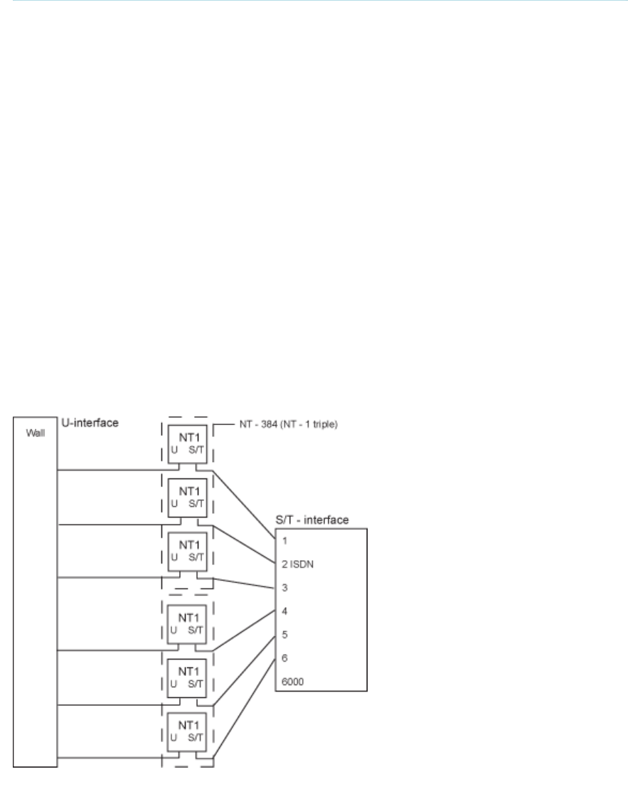
Appendices
255
6.10 Appendix 10
Connecting the system to ISDN using NT1 network
adapters
Connecting
Connect the first ISDN cable from ISDN 1 on the system to the S-interface on your first
NT1 network adapter. Connect the other ISDN cables to the appropriate NT1 network
adapters. Connect the U-interface of your NT1 adapter to the line provided from your
network provider.
For convenience the NT1 adapters could be placed inside the cabinet. If needed, use
the shorter ISDN cable (RJ45 connectors) delivered with the NT1 between the codec
and the NT1 and the longer ISDN cable between the NT1 and the connector (RJ45) at
the wall socket.
Configuring
The configuration of the system is performed in the same manner as described in
ISDN BRI Settings.
The NT1 should be powered up and you should check that the network is active.
Please check your NT1 User Manual.
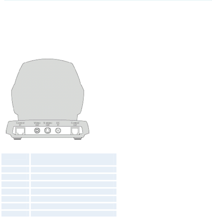
TANDBERG 3000 MXP
256
6.11 Appendix 11
(Not available with set top systems)
WAVE II Camera
Pinouts and Connectors
8-PIN RJ (shielded modular jack):
This connector is used for the power and control signals to the main camera.
Pin-8 +12V (presence when connected in
daisy chain)
Pin-7 GND
Pin-6 GND
Pin-5 RXD (in)
Pin-4 TXD (out)
Pin-3 +12V
Pin-2 GND
Pin-1 + 12V
Standard Phono:
Used for composite video signal
Power:
2.0 mm DC power jack (+12V, 1A required)
Standard Mini Din:
Used for S-Video signal
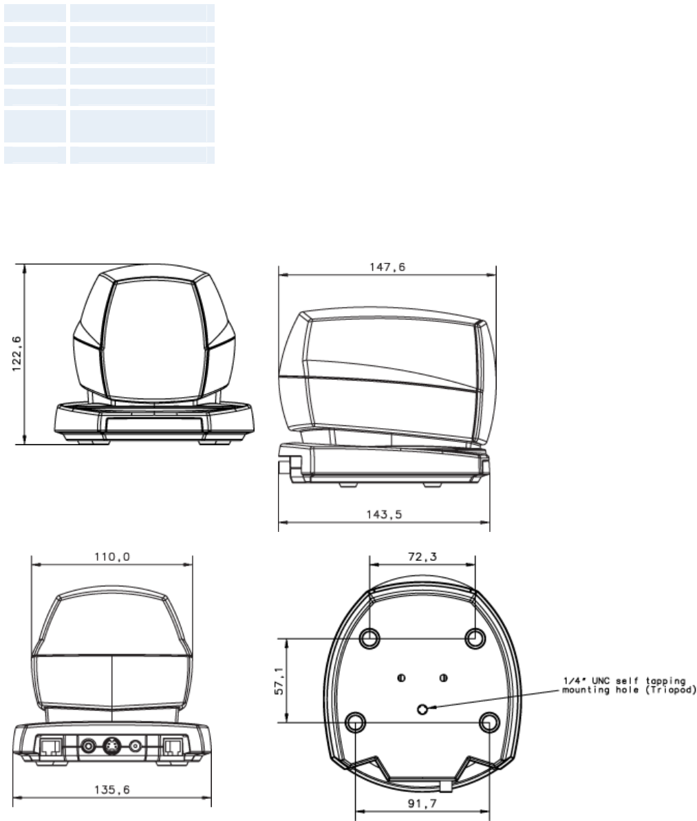
Appendices
257
6-PIN RJ (modular jack):
This connector is used when cascading cameras: Control (out) signal and external camera
detection. Note: It does not provide power for cascaded camera.
PRI Pinout
Pin-6 GND
Pin-5 GND
Pin-4 RXD (in)
Pin-3 TXD (out)
Pin-2 Presence (+12V in
daisy chain)
Pin-1 GND
Dimensions
Front view:
Side view:
Rear view:
Underside view:

TANDBERG 3000 MXP
258
6.12 Appendix 12
Remote Control (TRC 3 / TRC4)
The TANDBERG remote control transmits IR-signals using the following parameters:
Protocol Siemens SDA2208
Reference frequency 485kHz
Address 4 & 7
IR wavelenght 940nm
IR carrier ferquency 30kHz

Appendices
259
Remote Control keycode map:
Button
codes Remote control
(TRC 3 / TRC 4) Button
codes Remote Control
(TRC 3) Remote Control
(TRC 4)
Dec Hex Address Button name Dec Hex Address
Button
name Address Button
name
0 00 33 21 0 OK 0 OK
1 01 0 NUMBER 1 34 22 0 CALL 0 CALL
2 02 0 NUMBER 2 35 23 0 END
CALL 0 END CALL
3 03 0 NUMBER 3 36 24 0 PHONE
BOOK 0 PHONE
BOOK
4 04 0 NUMBER 4 37 25 0 MENU 0 MENU
5 05 0 NUMBER 5 38 26 0 CANCEL 0 CANCEL
6 06 0 NUMBER 6 39 27 0 0
7 07 0 NUMBER 7 40 28 0 LAYOUT 0 LAYOUT
8 08 0 NUMBER 8 41 29
9 09 0 NUMBER 9 42 2A 0 MAIN CAM
10 0A 0 NUMBER 0 43 2B 0 PC
11 0B 0 * 44 2C 0 DOC CAM
12 0C 0 # 45 2D 0 DVD
13 0D 46 2E 0 AUX
14 0E 47 2F 0 HELP
15 0F 48 30 0 FAR END
16 10 49 31 0 PRESETS
17 11 PRESENTER 50 32 0 SERVICES
18 12 0 51 33
19 13 52 34
20 14 53 35
21 15 54 36
22 16 0 ZOOM OUT 55 37
23 17 0 ZOOM IN 56 38
24 18 57 39
25 19 0 VOLUME
DOWN 58 3A
26 1A 0 VOLUME UP 59 3B
27 1B 0 MIC OFF 60 3C
28 1C 61 3D
29 1D 0 UP 62 3E
30 1E 0 DOWN 63 3F 0 WAKE
UP 0 WAKE UP
31 1F 0 LEFT 25 19 3 LOW
BATT 3 LOW
BATT
32 20 0 RIGHT XX 3 PROG
VER 3 PROG
VER

TANDBERG 3000 MXP
260
6.13 Appendix 13
Cisco CallManager registration
Configuring an H.323 client on the CallManager 4.0
The registration of a H.323 client in CallManager is supported on the CallManager (CCM) 4.0
software and forward.
1. To configure the CallManager with an H.323 client, log on to the administration web
interface and go to the phone configuration page.
2. The Phone configuration page is located on: device (top menu) -> Add a New device ->
Phone -> H.323 Client.
3. In the phone configuration page type the IP address of the TANDBERG system in the
Device name field, select device pool and push the insert button.
4. A pop-up box will now appear on the screen and ask you if you would like to configure
the directory number. Push the ok button.
5. You should now see the Directory Number Configuration WEB page. Enter the
E.164/phone number of your TANDBERG system in the Directory number field, and in
the “Forward and Pickup Settings” enter the time of “No Answer Ring Duration”. The time
selected has to have a value from 1 to 300 seconds.
6. Push the Add button to update the CallManager with the directory number settings.
You have now configured the CallManager with a H.323 client and should be able to register the
TANDBERG system to it.When the TANDBERG system is registered to a CallManager, it will be
possible to place and receive calls from this system to any other video and voice systems that are
registered on the same CallManager.

Appendices
261
6.14 Appendix 14
Diagnostic Tools for IP
To use these tools, will require using a PC and setting up a telnet session towards the system.
Q.931
To show Q.931 trace during a call you need to issue the command ‘syslog on’.One can get traces
for RAS, Q.931 and H.245 with this command. It is a complex trace and requires an extensive
knowledge in H.323 signalling to be understood.
Ping
Ping is used to see if the system is able to reach a specific IP-address, using a mechanism in IP
called ICMP. If the system is unable to register to its gatekeeper, or if it is unable to dial a specific
endpoint, one can use ping to see if there is at least an IP-route to the gatekeeper or to the
endpoint. In case you have problems, one would first ping the default gateway, then the
gatekeeper, and then the other endpoint.
Traceroute
Traceroute does exactly that; it traces the route an IP-packet takes to reach its destination and
displays all router hops. Traceroute is very useful for seeing exactly where there is a routing-
problem in the IP-network, and for checking where transport-delay is introduced.
Layer 4 Ports used in H.323 calls
The layer 4 ports used by the system in a H.323 call can be defined as follows:
Dynamic: The ports are allocated at random from 2048 to 65535.
Static: Will use the predefined layer 4 ports listed in the tables below.
Function Port Type
Gatekeeper Discovery (RAS) 1719 UDP
Q.931 Call Setup 1720 TCP
H.245 Range 5555-5574 TCP
Video Range 2326-2341 UDP
Audio Range 2326-2341 UDP
Data/FECC Range 2326-2341 UDP
Point-to-point + Duo Video

TANDBERG 3000 MXP
262
Function Port Type
Gatekeeper Discovery (RAS) 1719 UDP
Q.931 Call Setup 1720 TCP
H.245* Range 5555-5574 TCP
Video Range 2326-2405 UDP
Audio Range 2326-2405 UDP
Data/FECC Range 2326-2405 UDP
MultiSite + Duo Video
(*) Note: While using MultiSite, if a site is disconnected and reconnected without terminating the
entire conference, the next site to be connected will have a H.245 port outside of the specified
range. If this functionality is required through a firewall, the range of TCP ports can be extended
past 5564. However, if a site is disconnected and reconnected, without ending the conference
enough times one can quickly end up outside of this range again.

Appendices
263
6.15 Appendix 15
System Upgrade
Before starting the software upgrade of the TANDBERG MXP system, please make sure to have
the new software file, (for instance s050000F30.pkg) and the Release Key for this software
available. Your TANDBERG Partner will provide this for you.
All options and settings will automatically be stored when upgrading, so no backup is necessary.
If the system upgrade process is aborted before it's complete, the system will work as normal with
the original software
The TANDBERG MXP systems can be upgraded in three different ways;
Using the web interface
Using FTP
Using ISDN
A) To upgrade using the the web interface, please do the following steps:
1. Type the IP address of the TANDBERG MXP system that shall be upgraded (for instance
10.0.8.77) in a standard browser, such as Internet Explorer 6.0.
2. The web interface of the codec will then be displayed. Select the ‘System Configuration’ tab on
top of the page, and then the sub-tab ‘Upgrade’.
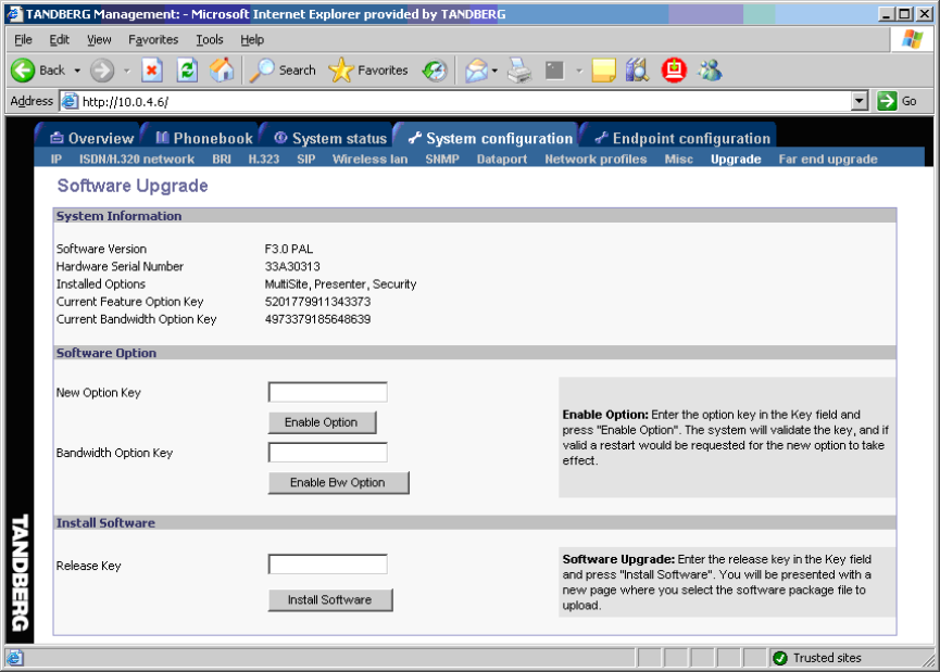
TANDBERG 3000 MXP
264
The following page will now be displayed:
Figure 1
3. Enter the Release key in the ‘Release Key’ field and press the ‘Install Software’ button.
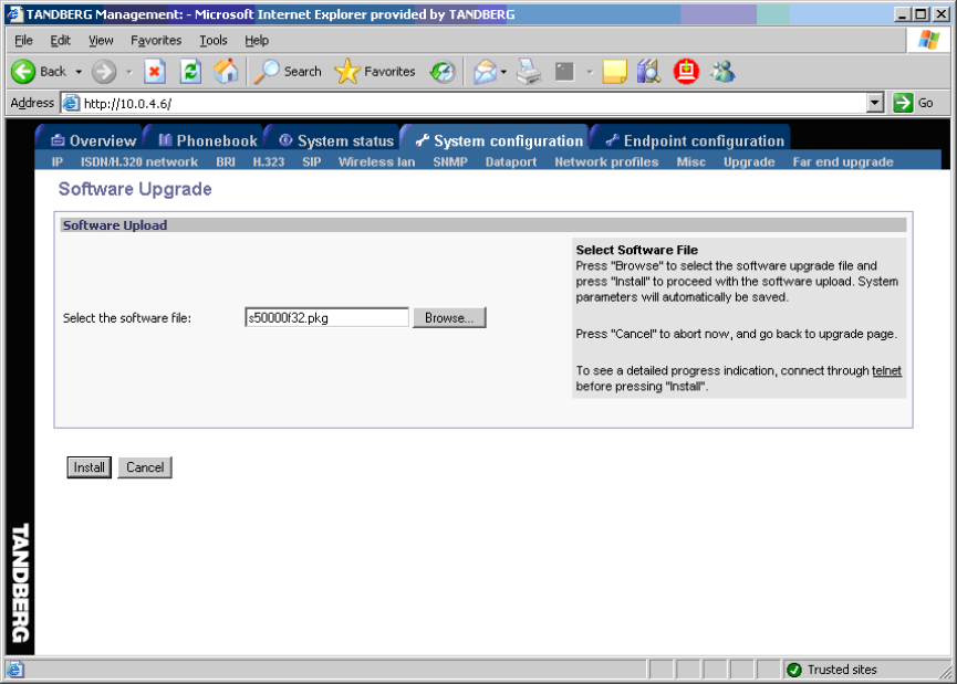
Appendices
265
A new page will now be displayed:
Figure 2
4. Type in the path to where the new software file is stored, or select the file by using the ‘Browse’
button.
5. The progress for the sw upgrade can be tracked by pressing the ‘telnet’ link in the help text box
BEFORE pressing the install button. Please note that this is not a necessary action for a
successful software upgrade. An indication of the software upgrade progress will also be shown
on the display of the system
6. Press the ‘Install’ button to start the software upgrade.
When the software upgrade is complete, you need to click on the restart button and press OK to
restart the system in order to activate the new software. Once verified, the system will reboot
once more to complete the upload of all systems parameters kept from the old software revision.
7. To verify that the new sw is installed, refresh the page shown in figure1 after restart. The
‘Software Version’ should now show the new software version uploaded to the system. The same
information can also be found in the menu on the system under ‘Control Panel/System
Information’.
B) Upgrading using FTP:
1. Copy the new software file to a folder on your harddisk, for instance c:\software.
2. Open a DOS window, and go to the folder where the new software is stored.
3. Type ftp <ip address of the TANDBERG MXP system>.
4. Type in the supplied ‘Release Key’ as user.
TANDBERG 3000 MXP
266
5. Type in your IP password (default is “TANDBERG”) as password.
6. Type ‘put <software file name> and press Enter. The new software file will now be
uploaded to the TANDBERG MXP system.
7. When the software upload is complete, end the ftp connection to the TANDBERG MXP
system by typing ‘bye’ in the DOS prompt.
8. To exit the DOS window completely, type ‘exit’
9. Restart the system to activate the new software.
C) ISDN Upgrade
The TANDBERG MXP systems has the possibility to be upgraded remotely from another
TANDBERG MXP system using ISDN. Please note that both systems must be on software
version F3.0 or newer for this functionality.
Please also note that both systems must be on software version F3.0 or newer for this
functionality
1. Connect to the system that shall be upgraded using ISDN
2. Copy the new software file to a folder on your computer, for instance c:\software.
3. Type the IP address of the TANDBERG MXP system that the software upgrade is going to be
done from (for instance 10.0.8.77) in a standard browser, such as Internet Explorer 6.0. The web
interface of the codec will then be displayed.
4. Select the ‘System Configuration’ tab on top of the page, and then the sub-tab ‘Far end
upgrade’.
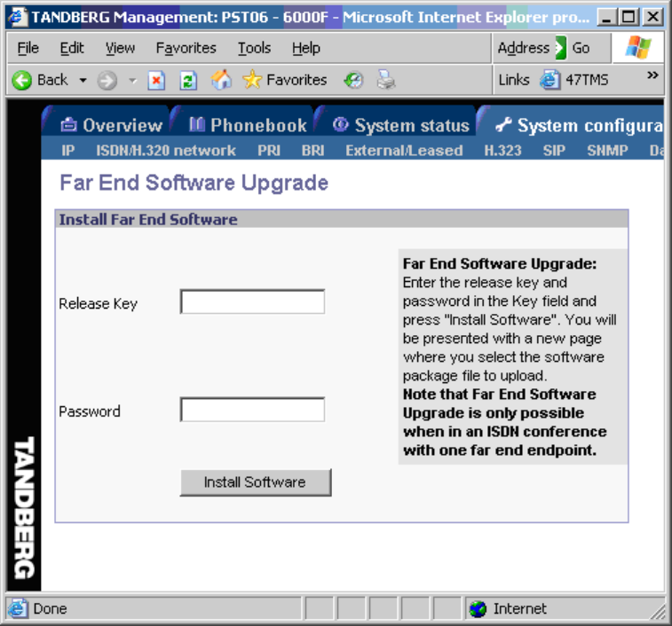
Appendices
267
The following page will now be displayed:
Figure 3
5. Enter the release key for the system to be upgraded in the ‘Release Key’ field. If no release
key is given, the Far End System will use the previously stored release key if possible. This will
work when upgrading from a main release to a dot release.
6 Make sure the setting “Far End System Upgrade” is set to “On” at the remote site. This setting
can be found in the Administrator Settings/General/Permissions menu.
7. Enter the password set at the far end for remote upgrade (default password is “TANDBERG”)
8. Press ‘Install Software' .The system will now use about 90% of the call capacity to transfer the
software file across. During this time, audio and video will be turned off.
9. Once the software has been transferred and verified at the far end, you will get a new webpage
with information that the upgrade of the far end was successful. At the same time, a message box
will appear at the remote system asking if you want to reboot the system to activate the new
software.
10. To activate the new software. The ISDN connection needs to be closed, and the TANDBERG
MXP system must be rebooted.
TANDBERG 3000 MXP
268
In the menu on the system under ‘Control Panel/System Information’, the installed software
should now be displayed as the ‘Software Version’.

Appendices
269
6.16 Appendix 16
Declaration of Conformity
Contact your TANDBERG representative for a Declaration of Conformity.
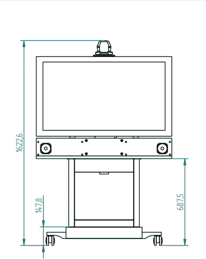
TANDBERG 3000 MXP
270
Appendix 17
Dimensions
Front view, 43'' monitor

Appendices
271
Front view, 32'' monitor
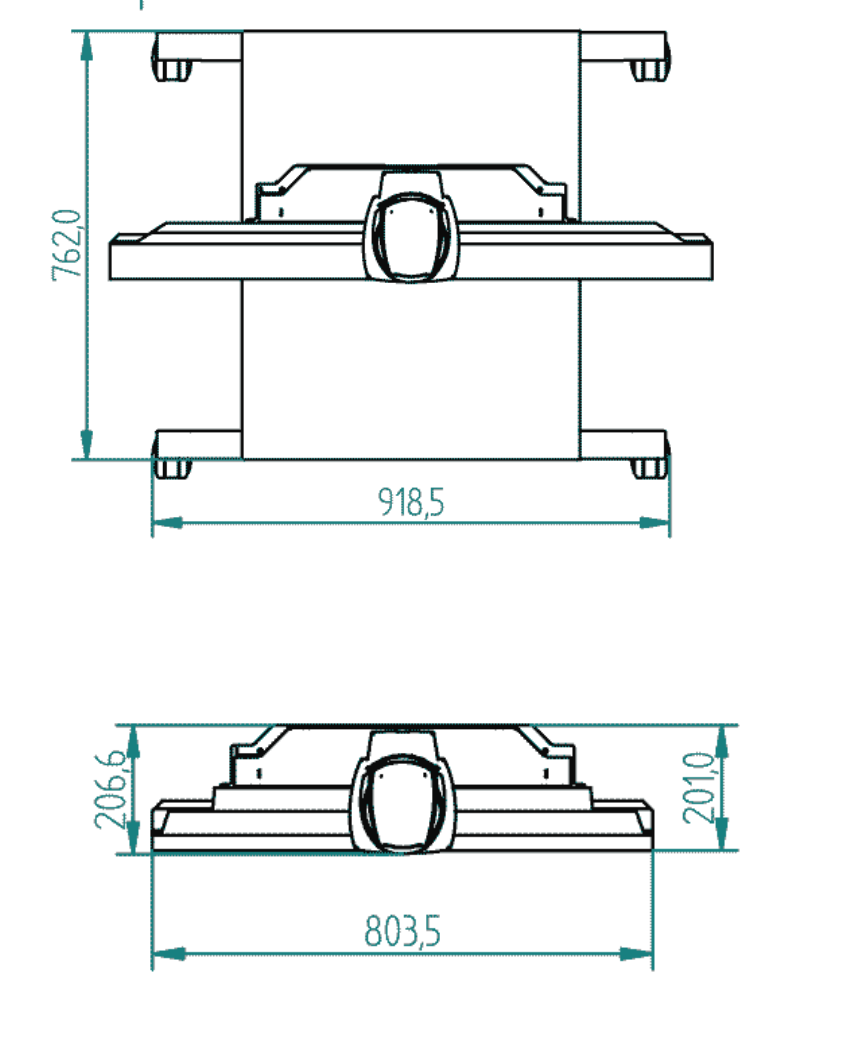
TANDBERG 3000 MXP
272
Top view, with base
Top view, 32'' monitor
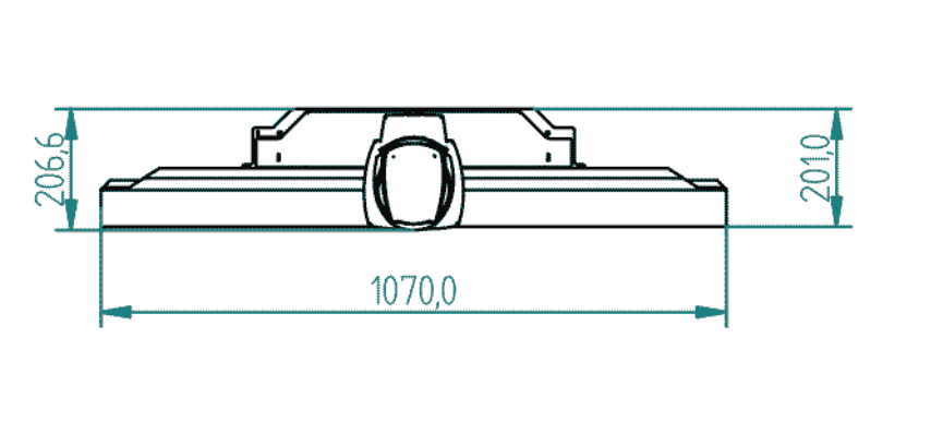
Appendices
273
Top view, 43'' monitor
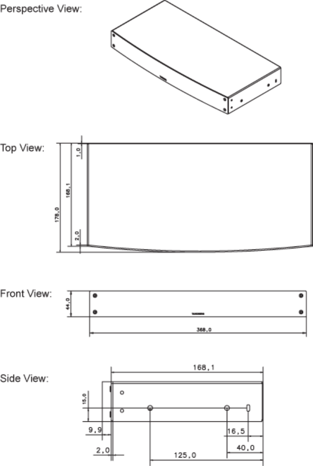
TANDBERG 3000 MXP
274
Codec
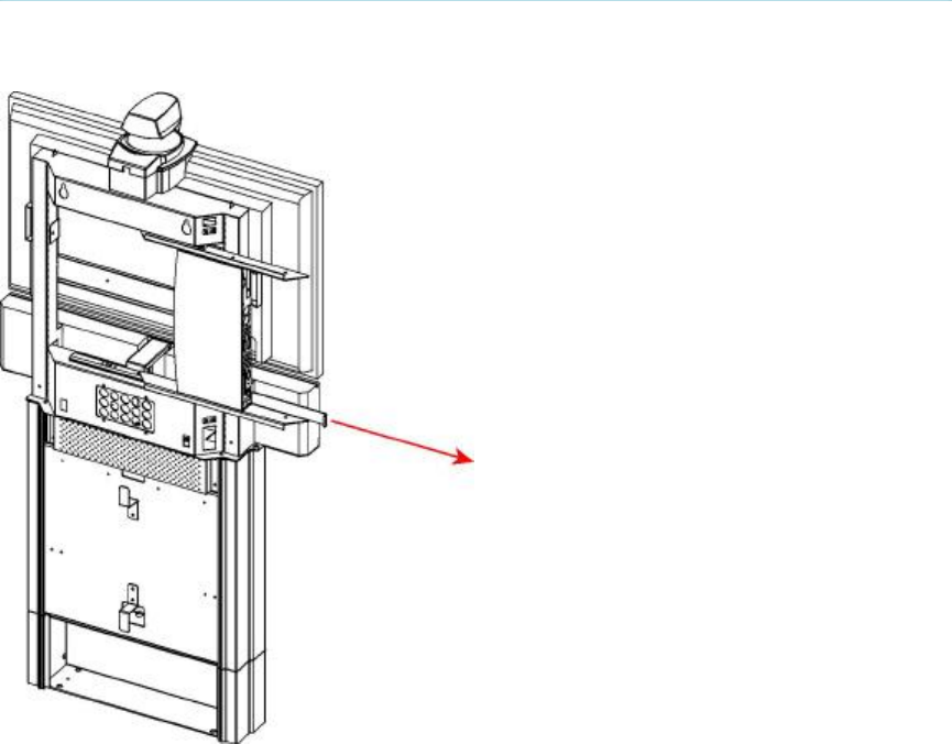
Appendices
275
6.17 Appendix 18
How to remove the codec
Pull out codec and remove cables
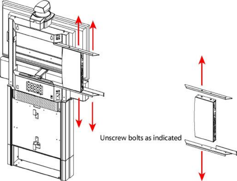
TANDBERG 3000 MXP
276
Unscrew bolts as indicated and change codec
277
7 Glossary
#
199 AV1: External input for the TANDBERG/LOEWE monitor.
2nd monitor: The second monitor of your videoconferencing system. The second monitor is
normally placed on the right side of the first monitor.
4CIF: 4 times CIF, 704x576 pixels
4SIF: 4 times SIF, 704x480 pixels
A
AACLD: Advanced Audio Coding Low Delay
Access code: Use Access code to password protect outgoing calls.
Accessories box: The cabinet contains the following: W.A.V.E. camera, table microphone,
remote control and tracker and documentation.
Accessories drawer: See Accessories box
AES: Strong encryption. (Advanced Encryption Standard)
AGC: Automatic Gain Control. Maintains the audio signal level at a fixed value by attenuating
strong signals and amplifying weak signals. Very weak signals, i.e. noise alone, will not
be amplified.
Alert speaker: The internal speaker will warn you of an incoming call even though the monitor
may not be switched on.
Audio call: Audio call equals a telephone call. You can make a call with the video system with
audio only.
Audio input 4: Intended for connection to an external microphone amplifier or an external fixed
mixer.
Audio input 5: Intended for connection to external playback devices (or to telephone add-on
hybrids).
Audio input 6: Intended for connection to a VCR or DVD player or other external playback
devices.
Audio out 1: Intended for connection to TANDBERG Natural Audio, televisions or audio
amplifiers.
Audio out 2: Intended for connection to audio recording equipment (or to a telephone add-on
hybrid).
Audio out 3: Intended for connection to a VCR or other recording equipment.
Auto-display snapshot: Sent and received snapshot will automatically appear on full screen
display.
Auto answer: The system will automatically answer all incoming calls.
Automatic Duo Video: Duo Video Mode is put to Auto. When starting a presentation, Duo Video
will start automatically (if possible).
TANDBERG 3000 MXP
278
B
Bandwidth: Decides the quality of the video call. High bandwidth gives high quality.
C
Call Control Data Triggered: Uses TxData, RxData and clock signals only. Use Data Triggered
when no handshake signal is available.
Call control Leased Line: Is a non-dialing protocol and should be used when two systems are
connected in a point-to-point connection. Use Leased Line when the handshaking signals
DTR and CD are available.
Call control Manual: Should be used when no handshake signals are available, and the external
equipment requires a constantly connected line.
Call control RS366 Dialing: The only dialing protocol and would normally be used together with
network clocking RS449/V35 Compatible when the external system uses RS2366 ports.
Call status: Comprehensive information about the call listing transmitted and received
audio/video/data information.
Camera tracking: Voice Activated Camera Positioning - the camera will automatically view the
current speaker.
Camera tracking mode: Voice Activated Camera Positioning - the camera will automatically
view the current speaker.
Chair control: Enables one participant to control the meeting by selecting which of the
conference participants that is to be broadcasted to the other participants.
Channel status: Comprehensive information about the call progress listing the numbers called,
and if an error occurs a cause code is displayed.
CIF: Common Intermediate Format, 352x288 pixels
Closed Captioning: Text chat.
Codec: The Codec is the heart of the system. The main task for the Codec is the compression of
outgoing video, audio and data, the transmission of this information to the far end, and
the decompression of the incoming information.
Continuous Presence: See Split Screen
Control Panel: The Control Panel is found in the main menu.
CSU: Channel Service Unit
D
Daisy-chaining: Use of several cameras in a video conference.
Dataport: The system provides two standard RS 232 data ports to allow a computer to be
connected for data transfer and control purposes.
Dataport 1: A standard RS 232 data port to allow a computer to be connected for data transfer
and control purposes.
Dataport 2: Dedicated to the main camera and will not be available in standard configuration.
DES: Encryption. (Data Encryption Standard)
DHCP: Dynamic Host Configuration Protocol.
Glossary
279
Diagnostics: Allows testing of individual system components and displays the current system
settings.
Digital ClarityTF: Participants enjoy presentations of exceptionally high quality resolution video.
Disconnect site: As a Chairman, you get the option Disconnect site. Disconnect site allows you
to disconnect any participant in the conference.
Do Not Disturb: When Do Not Disturb is active the system will not accept any incoming calls.
The caller will hear a busy tone when calling the unit.
Document Camera: A document camera is an additional camera that is used for showing text,
diagrams as well as physical objects.
DownspeedingTF: If channels are dropped during a videoconferencing session, the connection
is automatically maintained without interruption.
dual monitor: The second monitor
Dual monitor system: A videoconference system with two monitors.
Duo VideoTF: Allows participants at the far end to simultaneously watch a presenter on one
screen and a live presentation on the adjoining screen.
E
E.164 Alias: The E.164 address of the system. Equivalent to a telephone number, sometimes
combined with access codes. The system will not register with the gatekeeper if the E164
alias is not set.
E1: Network type, 30 channels. Default for PAL versions.
Echo canceller: Continuously adjusts itself to the audio characteristics of the room and
compensates for any changes it detects in the audio environment.
Echo control: When set to On the far end is prevented to hear their own audio.
Encryption: Use encryption to make a secure call. The system will try to make point-to-point
calls using encryption. If the far end system supports encryption, the call will be
encrypted. If not, the call will proceed without encryption. (Auto encryption). Set
encryption to On if you don't want an unencrypted call to be established at all. Set
encryption to Off if you don't want to use encryption.
End view: Stop viewing the site previously chosen with View Site, and return the view to the site
that is currently On Air. Can be used by all conference participants.
Ethernet Speed: The speed (Mbps) on the connection from the system to the LAN.
F
Fallback to telephony: Enables fallback from video calls to telephony/speech calls.
Far End: In a video conference, Far End means the remote side of the conference. Far End
Camera is your conference partner's camera. Opposite to Near End
FECC: Far End Camera Control. When activated it is possible to control the far end's camera,
select video sources, activate presets and request still images.
Floor: In a multipoint call, use Request Floor to broadcast your picture to all other participants.
This is handy when you are having presentations, for teachers etc.
TANDBERG 3000 MXP
280
G
G.711: Audio algorithm for normal quality audio (telephone quality, 3.1 kHz) The system will
always have G.711 enabled.
G.722: Audio algorithm for high quality audio (7 kHz).
G.722.1: Audio algorithm for compressed high quality audio (7 kHz)
G.728: Audio algorithm for compressed normal quality audio (telephone quality, 3.1 kHz)
Gateway: The gateway enables sites on IP and sites on ISDN to participate in meetings with
each other.
Global Phone Book: A phone book provided by TMS.
H
H.261: Video algorithm for legacy video compression and decompression. The system will always
transmit H.261
H.263: Video algorithm for normal video compression and decompression
H.264: Video algorithm for bandwidth-efficient video compression and decompression
Hardware serial number: A unique number (listed in the System Information menu) to identify
your system towards your TANDBERG representatives.
Humfilter: A highpass filter which reduces very low frequency noise.
I
iCIF: Interlaced CIF, 352x288 pixels, 50 fields per second
Incoming call: Someone calls in to your system
Incoming MCU Calls: If occupied in a call, the system will provide a visual/audio indication of an
incoming call and ask to accept or reject the call.
IP address: Defines the network address of the system. This address is only used in static mode.
IP assignment: IP-address, IP-subnet mask and Gateway are assigned by the DHCP server.
IP assignment Static: The system's IP-address and IP-subnet mask must be specified in the IP-
address field.
IP Precedence: Used to define which priority the system should have in the network. Higher
numbers indicate higher priority.
IP subnet mask: Defines the type of network. This address is only used in static mode.
IP TOS: IP Type Of Service. Helps a router select a router path when multiple paths are
available.
iSIF: Interlaced SIF, 352x240 pixels, 60 fields per second
L
Layout: Use the Layout key to change picture layout on the screen.
Glossary
281
M
Main Camera: Your camera. Video input 1
Max call length: This feature will automatically end both incoming and outgoing calls when the
call time exceeds the length specified.
Max channels: Indicates the maximum number of channels the system is allowed to use on the
E1/T1 interface.
MCU: Multipoint Conference Unit.
MCU status line: Shows indicators for MultiSite, MCU and DuoVideo
MicOff: Microphone is switched off.
Mix mode: How to adjust the weighting of each microphone to obtain the best possible audio and
minimize the background noise.
Modem mode: (Dataport) Supports external control of the system via a PC as in Control Mode.
Once a call is established, Dataport 1 will automatically switch to Data mode. When the
call disconnects, Dataport 1 switches back to Control Mode.
MSN: Multiple Subscriber Number. Possible to attach different ISDN terminals, with different
numbers, to the same physical ISDN telephone line. The service can be ordered from the
telephone company.
multipoint call: A call with more than two participants including yourself
MultiSite: The TANDBERG systems internal MCU. Built-in system which makes it possible to
establish meetings with up to 6 video calls and 5 telephone calls. The MultiSite option is
not available on all systems.
MultiSite cascading: By connecting up to 4 or 6 (depending on the system capacity) MultiSite
systems together to achieve a higher number of participants in a multipoint call.
N
NAT: Network Address Translation. NAT support in the videoconferencing system enables proper
exchange of audio/video data when connected to an external videoconferencing system
when the IP traffic goes through a NAT router. Used in small LANs, often home offices,
when a PC and a videoconferencing system is connected to a router with NAT support.
NAT Address: The external/global IP-address to the router with NAT support. Packets sent to
the router will then be routed to the system's IP address.
Natural Audio ModuleTM: Designed to improve audio quality during a videoconference. It is
mounted in the cabinet above the Codec and consists of an audio system optimized for
speech.
Natural Presenter Package: Consists of Duo Video, Digital Clarity and PC Presenter.
Natural VideoTF: 60 fields per second true interlaced picture.
Near End: In a video conference, Near End means your own side of the conference. Near
Camera is your own camera. Opposite to Far End
Network clocking: Specifies the number of physical external clock signals.
Network Interface: Indicates if the network is of type E1 or T1.
Network profiles: It is possible to define up to 6 network profiles, each consisting of name and
call prefix, and 3 of them also include network selection.
TANDBERG 3000 MXP
282
Non Standard Facility: The network provider may require service selection in your ISDN
configuration. Valid NSF codes are from 1 to 31. 0 will disable NSF service codes.
NR: Noise Reduction. Reduces constant background noise (e.g. noise from air-conditioning
systems, cooling fans, etc.).
NSF: Non Standard Facility.
NTSC: National Television System Committee. Video standard corresponding to 4SIF. Primary
used in USA, Japan and other countries.
O
Option Key: Required by the system to activate optional features such as MultiSite and
Presenter.
P
PAL: Phase Alternation by Line. Video standard corresponding to 4CIF. Primary used in Europe,
Middle East and Asia
Parallel dial: Channels will be dialed and connected in parallel when setting up a bonding call.
PC PresenterTF: An easily accessible PC connection plug. When connected the PC image is
displayed on the monitor.
PC SoftPresenterTF: Shows PC images via the LAN connection.
PIP: Picture-In-Picture
point-to-point call: A call with two participants including your self
POP: Picture Outside Picture. POP is a picture layout mode that is optimized for wide screens:
Full screen, 1+3 layout and emulated dual monitor layout.
Presentation: Presentation means to show another video source. Use the Presentation Key for a
predefined presentation source. Use the presentation menu to choose among all
available video sources.
Presentation source: The video source that is on display when you press the Presentation Key
on the remote control
Presets: Predefined camera positions (and video sources)
Q
QCIF: Quarter CIF, 176x144 pixels
QSIF: Quarter SIF, 176x120 pixels
R
Release Floor: To end the request floor function.
release floor to site: Allows the chairman to release the floor.
Remote: Short for Remote Control
Request Floor: The MCU will broadcast the video in full screen to all other participants in the
conference. If the MCU conference has a chairman, a request will be sent to the the
chairman.
Glossary
283
Restart: Restarts the system.
Restore defaults: Restores system settings to the factory defaults.
Restricted call: A call to a 56 kbps network. By default the system will dial an unrestricted call (a
call to a 64 kbps network) and downspeed to 56 kbps if necessary.
S
S-VHS: S-video
S-video: The standard camera uses one of the S-video inputs in the codec.
Selfview: Outgoing video. In most cases, the image of your self.
Serial number: A unique number (the hardware serial number, listed in the System Information
menu) to identify your system towards your TANDBERG representatives.
Side-by-Side: Side-by-side view means that two pictures are displayed side by side each other
on the screen. You will se two equally sized pictures.
SIF: Standard Input Format, 352x240 pixels
SNMP: Simple Network Management Protocol.
SNMP Community: SNMP Community names are used to authenticate SNMP requests. SNMP
requests must have a password in order to receive a response from the SNMP agent in
the system. The SNMP Community name is case sensitive.
SNMP Trap Host: Identifies the IP-address of the SNMP manager.
SNMP traps: Generated by the agent to inform the manager about important events.
SoftMux: Ensures high reliability and includes the unique Downspeeding feature. It also makes it
possible to dial to another videoconferencing equipment, phones and mobile phones in a
uniform way, and provides an on-screen, real-time feedback on the progress of a call.
Split Screen: All the participants in a MultiSite conference are displayed on the screen. (Former
Continuous Presence)
Start Channel: Indicates the firstE1/T1 channel the system is allowed to use. The setting might
be used when if the E1/T1 line is shared with other equipment.
Start up video source: The video source that is on display when the system wakes up from
standby mode.
Status Format: Provides call quality feedback on the status line.
Streaming: Allows broadcasting of audio/video via an IP network.
Streaming Address: Defined as the IP-address of a streaming client, streaming server or a
multicast address.
Streaming Address Port: If several codecs are streaming to the same IP-address, different
ports have to be used in order for the client to know which stream to receive.
Streaming Allow remote Start: Streaming can be started from the Videoconferencing system
using the remote control, by using the Data port, or from external user interfaces like the
Web-browser or Telnet session.
Streaming Announcements: The system will announce to the network that it is streaming. This
enables a streaming client (e.g. a PC) to connect to the system's streaming session.
Used by Cisco IP/TV.
Streaming Password: Prevents unauthorized access to the streaming functionality.
TANDBERG 3000 MXP
284
Streaming Source: Select between local video and/or far end video to be streamed. Local and
far end audio is always streamed.
Streaming TTL/Router Hops: Used for streaming data to limit how many routers the data should
pass before it is rejected.
Streaming Video Rate: Defines the Video streaming rate from the system.
SVGA: Super VGA. (800x600)
SXGA: Super extended Graphics Array (1280x1024)
System information: Lists system numbers, line status, software version and other useful
information.
System name: Identifies a videoconferencing system
T
T1: Network type, 24 channels. Default for NTSC versions.
T1 Line Coding: Indicates how the signals on the line should be coded. If parts of the systems
use restricted coding, this should be selected.
Take chair: Request chairmanship of the conference. If no one else is chairman, the request is
granted.
TCS-4: Used to address different systems on a LAN when dialing in via a gateway.
Terminal Names: Lists the site numbers or name (if supported) of other sites connected in the
conference.
Terminate meeting: The chairman can terminate the conference, i.e. all participants are
disconnected.
TMS: TANDBERG Management Suite
Touch Tones: To dial extension numbers etc. during a call, use touch tones in order to get tones
instead of preset on the number keys.
Tracker: The tracker is a small infrared remote control device made to steer the camera to any
desired location within the room.
TSC-1: TCS-1 is used for H243 password on H320 MCU's
V
VCR: Video Cassette Recorder
VGA: Video Graphics Array. (640 x 480)
VGA Out Quality: Changes the resolution of the VGA signal available in the VGA Out connector
at the rear of the codec.
View administrator settings: Displays all the system settings in a read only format.
View site: View any participant in the conference other than the participant currently On Air. Can
be used by all conference participants.
VNC: Virtual Network Computing.
Voice Switched: The active site will be displayed in full screen during a MultiSite conference.
Glossary
285
W
WAVE II Camera: Wide Angle View Camera - delivers the widest angle of view in the industry.
Welcome menu: The welcome menu displays the main menu when you are outside a call.
X
XGA: extended Graphics Array (1024 x 768)
287
8 Index
A
Access Code......................................90, 114
Add Another Call........................................37
Additional microphone .............................224
Administrator Password...........................130
Alert Speaker...........................................170
Alert Tones and Volume ..........................170
Allowance ................................................114
Answer an incoming Call ...........................42
Assign Floor to Participant.........................83
Audio
Inputs ...................................................160
Outputs.................................................164
Audio Algorithm .......................................149
Audio Demo.............................................102
Audio Leveling (AGC)..............................169
AudioScience microphone.......................224
Auto answer.............................................111
Auto-Display Snapshot ............................143
Automatic Camera Tracking......................67
B
Battery handling.......................................... iii
C
Call Settings...............................................39
Call Status .................................................92
Camera Port ............................................207
Camera Presets.........................................64
Camera Tracking Mode ...........................172
Contact us................................................... vi
D
Default Call Settings ................................156
Digital Clarity............................................153
Disconnect Participant...............................85
Display snapshot .................................74, 75
Do Not Disturb ...........................................47
Document camera ...................................220
Dual Monitor ............................................232
Dual Stream.......................73, 138, 139, 141
Dual Video Stream.............73, 138, 139, 141
Duo Video..........................73, 138, 139, 141
Duo Video Quality....................................153
E
Echo Control............................................166
EDID ........................................................236
Encryption................................................180
End Call .....................................................43
Extra cameras..........................................223
F
Far End Camera Control ...........................62
Far End Control .........................................63
G
Gatekeeper ............................................. 191
Group Layout ............................................ 80
H
H.239 ................................ 73, 138, 139, 141
Hardware serial number ........................... 90
I
Indicators .................................................. 30
Interfaces ................................................ 210
IP Address Conflict Check ........................ 98
IP Settings............................................... 189
L
Language................................................ 108
Layout ....................................................... 25
Letter keys ................................................ 28
M
MCU.......................................................... 87
MCU Status Line..................................... 173
Menu timeout in call................................ 126
Mic off ....................................................... 26
Microphone ............................................. 224
MultiSite .................................................... 87
MultiSite (Built-in)...................................... 87
N
Natural Video .......................................... 151
Navigation ................................................. 22
Network Profiles...................................... 205
Number keys............................................. 28
P
PC Presenter ............................................ 71
PC Soft Presenter..................................... 72
PC SoftPresenter...................................... 72
Permissions ............................................ 114
Phone Book
Delete .................................................... 56
Edit ........................................................ 55
MultiSite................................................. 53
New ....................................................... 52
Picture Control .......................................... 66
PIP Appearance...................................... 144
PIP Placing ............................................. 145
Postpone 1 hour........................................ 45
Postpone 3 hours...................................... 46
Presentation
Presentation Key........................... 69, 141
Presentation Menu ................................ 70
Presentation.............................................. 68
Presentation Source ............................... 141
Presets...................................................... 64
Production of products................................iii
TANDBERG 3000 MXP
288
R
Release Chair............................................82
Release Floor ............................................79
Release Floor from Participant..................83
Request Floor ............................................79
Restart .....................................................104
Restore defaults.......................................208
S
Screen Settings .......................................116
Search .......................................................59
Selfview .....................................................23
SIP ...........................................................195
Snapshot..............................................74, 75
Snapshot Source .....................................142
Software Options .....................................122
Start up Video Source .............................140
Stereo I/O mode ......................................167
Stereo speakers.......................................167
Streaming ..................................................40
System Information....................................90
System Name ..........................................109
T
Take Chair .................................................82
Take new snapshot .............................74, 75
Telephone Add-On ..................................231
Telephone Call...........................................36
Terminate Meeting.....................................86
Test Subsystem ........................................ 93
Text Chat ................................................ 101
Timeout ................................................... 126
To connect a PC to Dataport 1 ............... 206
Touch Tones............................................. 29
U
User Guide.............................................. 105
V
Video Algorithm....................................... 148
Video Call.................................................. 35
Video cassette recorder (VCR)............... 221
Video Name ............................................ 178
Video Quality........................................... 153
View Administrator Settings...................... 94
View Site ................................................... 84
VNC Settings .......................................... 146
Volume + and - ......................................... 27
W
Warnings................................................... 99
Waste handling ...........................................iii
WAVE II camera ..................................... 256
Web Snapshots....................................... 175
Welcome menu....................................... 134
Welcome Screen....................................... 17
X
XGA ........................................................ 116
