Tandberg Tc2 1 Users Manual
TC2.1 to the manual 4af2806d-6a6a-459d-801a-ed5b803478fd
2015-02-03
: Tandberg Tandberg-Tc2-1-Users-Manual-462432 tandberg-tc2-1-users-manual-462432 tandberg pdf
Open the PDF directly: View PDF ![]() .
.
Page Count: 90
- Introduction
- Getting started
- About the menus
- The system settings menus
- The system settings library
- Description of the System settings
- The Audio settings
- The Camera settings
- The Conference settings
- The H323 Profile settings
- The Network settings
- The Network Services settings
- The Phonebook settings
- The Provisioning settings
- The Serial Port settings
- The SIP Profile settings
- The Standby settings
- The System Unit settings
- The Time settings
- The Video settings
- Description of the System settings
- Cameras
- Appendices
- General room guidelines
- Guidelines for meeting room setup
- TANDBERG Remote Control TRC5
- Password protection
- Startup script
- The web interface
- TANDBERG DNAM for Profile 42”/52”
- TANDBERG DNAM for Profile 65”
- Supported RFCs in SIP
- China RoHS table
- CE Declaration for TANDBERG Profile
- Dimensions
- Profile 42” with standalone foot
- Profile 42” with wall mount foot
- Profile 42” with wheelbase foot
- Profile 52” with standalone foot
- Profile 52” with wall mount foot
- Profile 52” with wheelbase foot
- Profile 52” Dual with standalone foot
- Profile wall mount setup
- Profile 65” with standalone foot
- Profile 65” with wall mounting foot
- PrecisionHD 1080p camera
- Technical specifications for Profile 42”/52”
- Technical specifications for Profile 65”
D14324.04—DECEMBER 2009 1
Profile series with Codec C60 Administrator Guide
Software version TC2.1
DECEMBER 2009
Contents Introduction Getting started About the menus The settings menu Settings Library Cameras Appendices Contact us
Administrator Guide
TANDBERG Profile
- with Codec C60
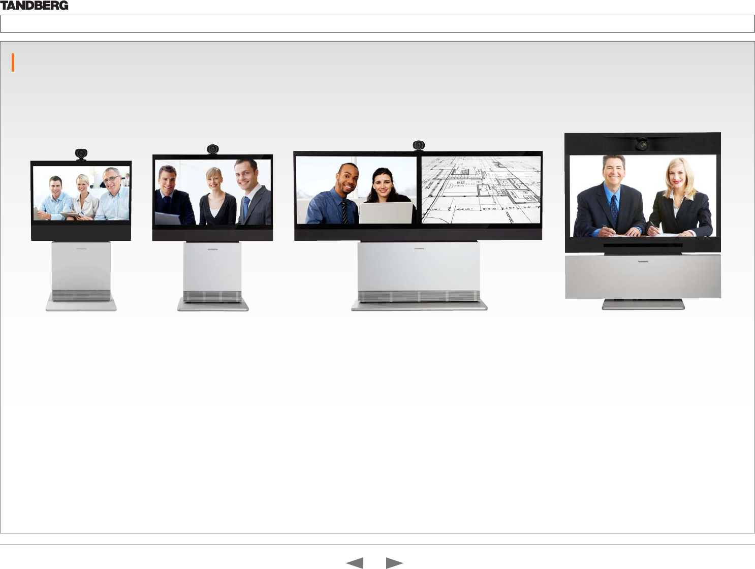
Profile 42” Profile 52” Profile 52” Dual Profile 65”
Contents
Contact us
Introduction
Getting started
About the menus
The Settings menu
The Settings library
Cameras
Appendices

D14324.04—DECEMBER 2009 2
Profile series with Codec C60 Administrator Guide
Hidden text anchor
Contents Introduction Getting started About the menus The settings menu Settings Library Cameras Appendices Contact us
The top menu bar and the entries in the Table
of Contents are all hyperlinks, just click on
them to go to the topic.
We recommend you visit the TANDBERG
web site regularly for updated versions of this
guide. Go to: http://www.tandberg.com/docs
Table of Contents
Introduction
What’s new ...................................................................................5
What’s new this guide ............................................................... 5
What’s new in this software version ..........................................5
Intellectual Property Rights ........................................................... 6
Trademark ..................................................................................... 6
Disclaimer ..................................................................................... 6
Patent Information ......................................................................... 6
Copyright and License Notice ....................................................... 6
Safety Instructions ........................................................................ 7
Safety Instructions .................................................................... 7
FCC rules 15B, acc. to Class A limits ........................................ 8
EMC A-Class declaration .......................................................... 8
FCC rules 15B, acc. to Class A limits ........................................ 8
EMC A-Class declaration .......................................................... 8
Environmental Issues .................................................................... 9
Getting started
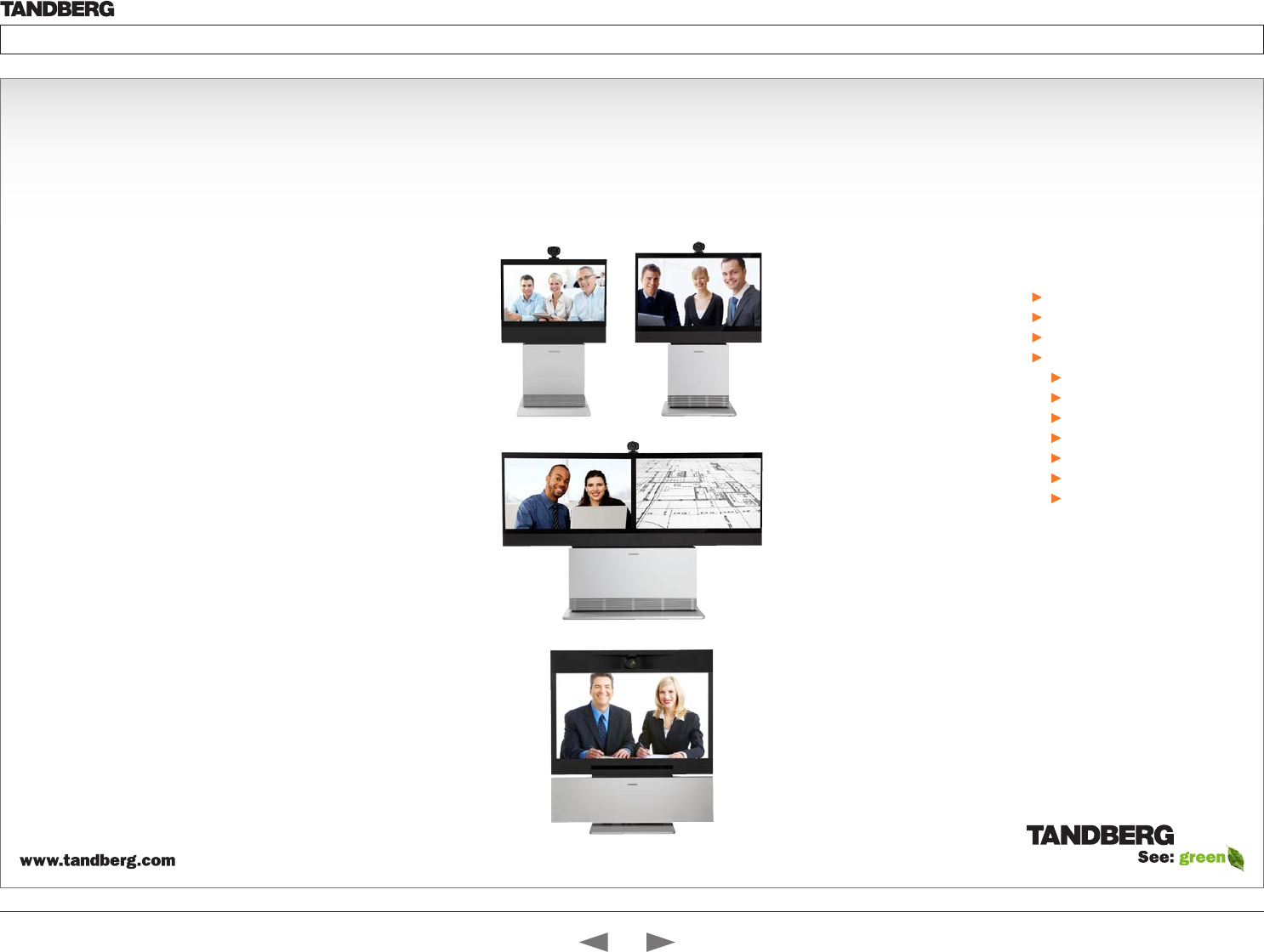
System overview ......................................................................... 11
TANDBERG Profile 42” ............................................................ 11
TANDBERG Profile 52” ............................................................ 12
TANDBERG Profile 52” Dual.................................................... 13
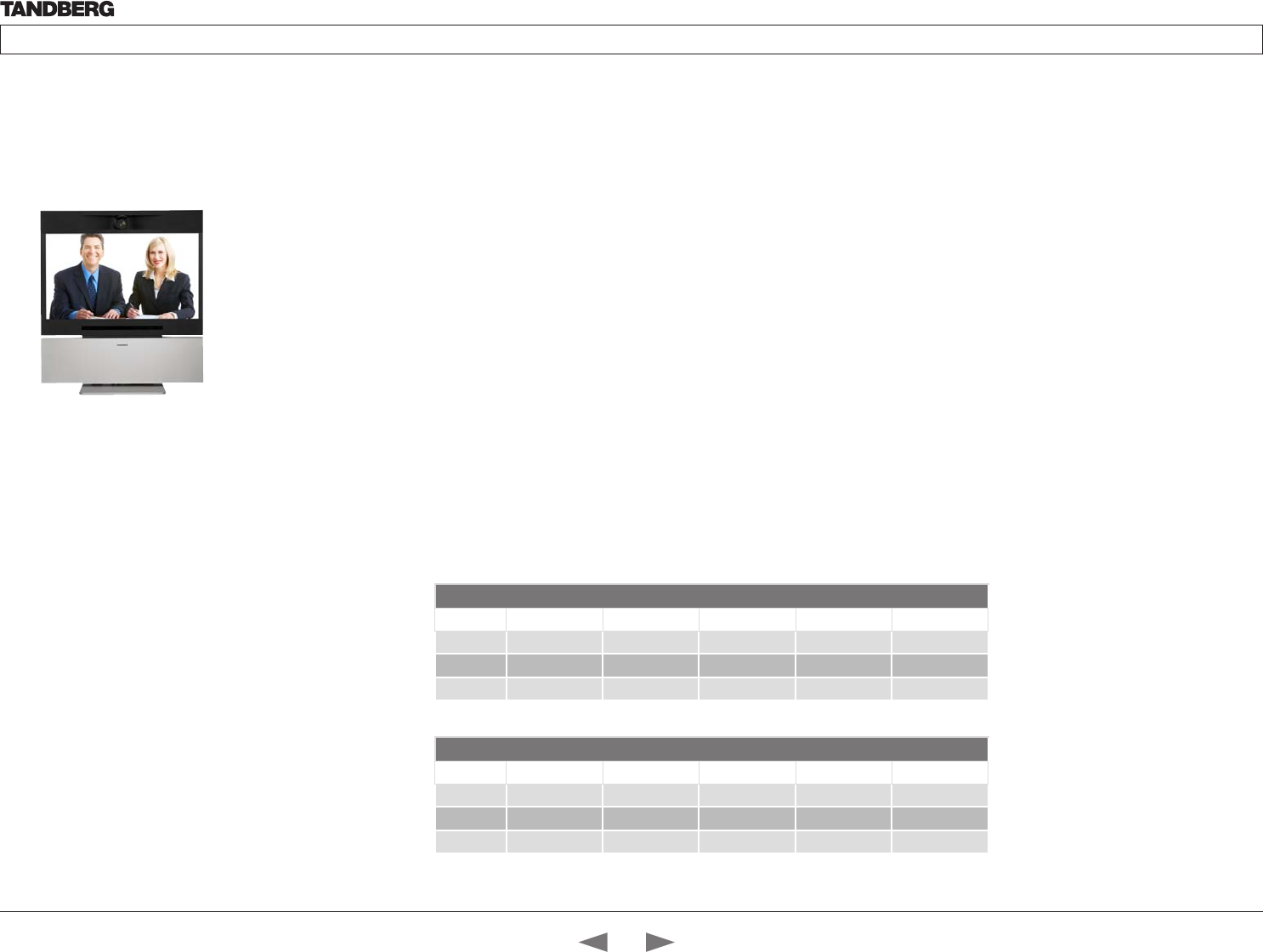
TANDBERG Profile 65” ............................................................ 14
Codec cable configuration .......................................................... 15
Using the Remote Control ........................................................... 16
Initial configurations .................................................................... 18
Waking up the system ............................................................. 18
Verify IP address settings ........................................................ 18
If you need to set a static IP address ...................................... 18
Adding the system to the network .......................................... 19
Verify your settings .................................................................. 19
Adjusting the date and time settings ....................................... 19
Setting a menu password ....................................................... 20
About the menus
The Home menu ......................................................................... 22
The Settings menu ...................................................................... 22
The Advanced menu ................................................................... 22
The system settings menus
The Advanced menus ................................................................. 24
How to change a value............................................................ 24
Description of each setting ..................................................... 24
The search functionality .......................................................... 25
How to change the menu password ....................................... 26
The system settings library
Description of the System settings .............................................. 28
The Audio settings .................................................................. 28
The Camera settings ............................................................... 30
The Conference settings ......................................................... 31
The H323 Profile settings ........................................................ 32
The Network settings .............................................................. 33
The Network Services settings ............................................... 35
The Phonebook settings ......................................................... 37
The Provisioning settings ........................................................ 37
The Serial Port settings ........................................................... 37
The SIP Profile settings ........................................................... 38
The Standby settings .............................................................. 39
The System Unit settings ........................................................ 39
The Time settings.................................................................... 40
The Video settings .................................................................. 41
Cameras
The PrecisionHD 1080p camera .................................................48
Connecting the camera .......................................................... 49
Best view—Face recognition ...................................................50
Using Best view ..................................................................50
Video output formats .............................................................. 51
DIP switch settings for video output formats ...................... 51
Line voltage frequency ........................................................ 51
What’s in
this guide?
Contents
Introduction
Getting started
About the menus
The Settings menu
The Settings library
Cameras
Appendices
Contact us
Contents

D14324.04—DECEMBER 2009 3
Profile series with Codec C60 Administrator Guide
Contents Introduction Getting started About the menus The settings menu Settings Library Cameras Appendices Contact us
Appendices
General room guidelines ............................................................. 53
The physical conditions ..........................................................53
The room equipment............................................................... 53
Environmental considerations .................................................53
The audio quality ..................................................................... 54
Natural communication ...........................................................54
Guidelines for meeting room setup ............................................. 55
Sharing a PC presentation ...................................................... 56
Other presentation sources .................................................... 56
TANDBERG Remote Control TRC5 ............................................. 57
Password protection ................................................................... 58
Setting the codec administrator password ............................. 58
Password protection of the web interface ........................... 58
Setting the menu password .................................................... 58
Startup script .............................................................................. 59
Adding a startup script ........................................................... 59
The web interface ....................................................................... 60
Password protection of the web interface ...............................60
The system info page ..............................................................60
The Upgrade software page ................................................... 61
The Advanced configuration page ..........................................62
The Advanced configuration, search functionality ..................63
The Wallpaper page ................................................................ 64
The Call page ..........................................................................65
The SSL Certificates page ......................................................66
The XML files page .................................................................. 67
The Logs page ........................................................................68
The Add release key page .......................................................69
TANDBERG DNAM for Profile 42”/52” ......................................... 70
The DNAM Loudspeaker Cabinet ........................................... 70
The DNAM Amplifier................................................................ 70
TANDBERG DNAM for Profile 65” ............................................... 71
The DNAM Loudspeaker Cabinet ........................................... 71
The DNAM Amplifier................................................................ 71
Supported RFCs in SIP ............................................................... 72
Current RFCs and drafts supported in SIP ............................. 72
Media capabilities supported in SIP ........................................ 72
China RoHS table ....................................................................... 73
CE Declaration for TANDBERG Profile ........................................ 74
Dimensions ................................................................................. 75
Profile 42” with standalone foot............................................... 75
Profile 42” with wall mount foot ............................................... 76
Profile 42” with wheelbase foot ............................................... 77
Profile 52” with standalone foot............................................... 78
Profile 52” with wall mount foot ............................................... 79
Profile 52” with wheelbase foot ............................................... 80
Profile 52” Dual with standalone foot ...................................... 81
Profile wall mount setup .......................................................... 82
Profile 65” with standalone foot............................................... 83
Profile 65” with wall mounting foot .......................................... 84
PrecisionHD 1080p camera .................................................... 85
Technical specifications for Profile 42”/52”.................................. 86
Technical specifications for Profile 65” ........................................ 88
Contents
Introduction
Getting started
About the menus
The Settings menu
The Settings library
Cameras
Appendices
Contact us
Contents

D14324.04—DECEMBER 2009 4
Profile series with Codec C60 Administrator Guide
Contents Introduction Getting started About the menus The settings menu Settings Library Cameras Appendices Contact us
Introduction
In this chapter...
TANDBERG Profile At a glance
Intellectual property rights
Trademark
Copyright
Disclaimer
Patent information
Safety instructions
Environmental issues
Chapter 1
Thank you for choosing TANDBERG!
TANDBERG Profile has been designed
to give you many years of safe, reliable
operation.
How to read this document
You will find that some places information
has been copied from other chapters (but
adapted, when needed) to let you have all
the relevant information there and then.
This helps eliminating the need to read
through long sections before you can even
think of getting started.
Our main objective with this user guide is
to address your goals and needs. Please
let us know how well we succeeded!
We recommend you visit the TANDBERG
web site regularly for updated versions of
the manual.
Go to: http://www.tandberg.com/docs
Contents
Introduction
Getting started
About the menus
The Settings menu
The Settings library
Cameras
Appendices
Contact us
Introduction
D14324.04—DECEMBER 2009 5
Profile series with Codec C60 Administrator Guide
Contents Introduction Getting started About the menus The settings menu Settings Library Cameras Appendices Contact us
What’s new
What’s new this guide
The TANDBERG Profile 65” with Codec C60 has been added to the
Profile series and is described in this guide.
What’s new in this software version
The latest software versions for the Codec C60 is TC2.1. The
Advanced configurations menu changes are described on this page.
For a complete overview of the news and changes from TC2.0
to TC2.1 we recommend reading the software release notes
TANDBERG TC Software Release Notes (TC2).
Go to: http://www.tandberg.com/docs
Advanced configuration —Settings added
Standby StandbyAction
Value space: <None/PrivacyPosition>
• None: No action.
• PrivacyPosition: Turns the camera to a sideways position for
privacy.
NOTE! The settings within the Experimental menu can be used
‘as is’. The content of the Experimental menu will change in future
software releases.
Experimental Audio Input Microphone [1..4] EchoControl
HighPassFilter
Value space: <On/Off>
Experimental Video OptimalDefinition Profile
Value space: <Normal/Medium/High>
See the table below to find when to choose Normal, Medium or
High for the optimal definition profile.
Advanced configuration —Value space changed
SerialPort BaudRate
Previous version: <9600/19200/38400/115200>
New value space: <9600/19200/38400/57600/115200>
SystemUnit MenuLanguage
Previous version: <English/Norwegian/Swedish/German/
French/Italian/Japanese/Chinese/Russian/Spanish/
Korean/Turkish>
New value space: <English/Norwegian/Swedish/German/
French/Italian/Japanese/Russian/Spanish/Korean/
Finnish/ChineseSimplified/ChineseTraditional/
PortugueseBrazilian/Turkish/Polish>
Advanced configuration —Removed settings
The Experimental settings are subject to change without notice.
They can be used “as is”. In version TC2.1 the following settings are
removed:
Experimental Audio Input Line [3..4] Equalizer Mode
Experimental Audio Input Line [3..4] Equalizer Number
Experimental Audio Output Line [3..6] Equalizer Mode
Experimental Audio Output Line [3..6] Equalizer Number
Experimental SoftwareUpgrade Mode
Experimental SoftwareUpgrade ServerAddress
Experimental > Video > Optimal definition, for systems supporting 1080p
w288p30 w448p30 w576p30 720p30 1080p30
Normal 256kbit/s 512 kbit/s 768 kbit/s 1152 kbit/s 2560 kbit/s
Medium 128kbit/s 384 kbit/s 512 kbit/s 768 kbit/s 1920 kbit/s
High 128kbit/s 256 kbit/s 512 kbit/s 768 kbit/s 1472 kbit/s
Experimental > Video > Optimal definition, for systems supporting 720p60
w144p60 w288p60 w448p60 w576p60 720p60
Normal 128kbit/s 512 kbit/s 1152 kbit/s 1472 kbit/s 2240 kbit/s
Medium 128kbit/s 384 kbit/s 768 kbit/s 1152 kbit/s 1472 kbit/s
High 128kbit/s 256 kbit/s 512 kbit/s 768 kbit/s 1152 kbit/s
Contents
Introduction
Getting started
About the menus
The Settings menu
The Settings library
Cameras
Appendices
Contact us
Introduction

D14324.04—DECEMBER 2009 6
Profile series with Codec C60 Administrator Guide
Contents Introduction Getting started About the menus The settings menu Settings Library Cameras Appendices Contact us
Intellectual Property Rights
This Administrator Guide and the Products to which it relates contain
information that is proprietary to TANDBERG and its licensors.
Information regarding the Products is found on the page entitled
License Agreements and Patent Information.
This Administrator Guide may be reproduced in its entirety,
including all copyright and intellectual property notices, in limited
quantities in connection with the use of the Products. Except for
the limited exception set forth in the previous sentence, no part of
this Administrator Guide may be reproduced, stored in a retrieval
system, or transmitted, in any form, or by any means, electronically,
mechanically, by photocopying, or otherwise, without the prior written
permission of TANDBERG. Requests for such permission should be
addressed to tandberg@tandberg.com.
Trademark
TANDBERG® is a registered trademark belonging to Tandberg ASA.
Other trademarks used in this document are the property of their
respective holders.
COPYRIGHT © 2008–2009, TANDBERG
All rights reserved.
Philip Pedersens vei 20
1366 Lysaker, Norway
Tel: +47 67 125 125 Fax: +47 67 125 234
E-mail: tandberg@tandberg.com
Disclaimer
The specifications for the Products and the information in this
document are subject to change at any time, without notice, by
TANDBERG.
Every effort has been made to supply complete and accurate
information in this Administrator Guide, however, TANDBERG
assumes no responsibility or liability for any errors or inaccuracies that
may appear in this document.
INTELLECTUAL PROPERTY RIGHTS
The Products that are covered by this Administrator Guide are
protected under copyright, patent, and other intellectual property
rights of various jurisdictions. Any applicable software licenses and
any limited warranty are located in the Copyright and License Notice
section in this guide.
This Product is
COPYRIGHT © 2008–2009, TANDBERG
All rights reserved.
Patent Information
The products described in this manual are covered by one or more of
the following patents:
US6,584,077 US5,838,664 US5,600,646
US5,003,532 US5,768,263 US5,991,277
US7,034,860 US7,010,119 EP01953201
US6.731.334 GB1338127
Other patents pending.
Please view www.tandberg.com/tandberg_pm.jsp for an updated
list
Copyright and License Notice
The product that is covered by this Administrator Guide is protected
under copyright, patent, and other intellectual property rights of
various jurisdictions. This product is Copyright © 2009, Tandberg
Telecom AS. All rights reserved. This product includes copyrighted
software licensed from others.
A document describing the copyright notices and the terms and
conditions of use can be found at: http://www.tandberg.com/docs
See the document: TANDBERG Codecs C90C60C20 Copyright and
License_Information (TC20).pdf.
IMPORTANT: USE OF THIS PRODUCT IS SUBJECT IN ALL CASES
TO THE COPYRIGHT RIGHTS AND THE TERMS AND CONDITIONS
OF USE REFERRED TO ABOVE. USE OF THIS PRODUCT
CONSTITUTES AGREEMENT TO SUCH TERMS AND CONDITIONS.
Contents
Introduction
Getting started
About the menus
The Settings menu
The Settings library
Cameras
Appendices
Contact us
Introduction

D14324.04—DECEMBER 2009 7
Profile series with Codec C60 Administrator Guide
Contents Introduction Getting started About the menus The settings menu Settings Library Cameras Appendices Contact us
Safety Instructions
For your protection please read these safety
instructions completely before you connect the
equipment to the power source. Carefully observe
all warnings, precautions and instructions both on
the apparatus and in these operating instructions.
Retain this manual for future reference.
Safety Instructions
Water and Moisture
Do not operate the apparatus under or near water – for example near a
bathtub, kitchen sink, or laundry tub, in a wet basement, near a swimming pool
or in other areas with high humidity.
• Never install jacks for communication cables in wet locations unless the
jack is specifically designed for wet locations.
• Do not touch the product with wet hands.
Cleaning
Unplug the apparatus from communication lines, mains power-outlet or any
power source before cleaning or polishing. Do not use liquid cleaners or
aerosol cleaners. Use a lint-free cloth lightly moistened with water for cleaning
the exterior of the apparatus.
Ventilation
Do not block any of the ventilation openings of the apparatus. Never cover the
slots and openings with a cloth or other material. Never install the apparatus
near heat sources such as radiators, heat registers, stoves, or other apparatus
(including amplifiers) that produce heat.
Do not place the product in direct sunlight or close to a surface directly heated
by the sun.
Lightning
Never use this apparatus, or connect/disconnect communication cables or
power cables during lightning storms.
Dust
Do not operate the apparatus in areas with high concentration of dust.
Vibration
Do not operate the apparatus in areas with vibration or place it on an unstable
surface.
Power Connection and Hazardous Voltage
The product may have hazardous voltage inside.
• Never attempt to open this product, or any peripherals connected to the
product, where this action requires a tool.
• This product should always be powered from an earthed power outlet.
• Never connect attached power supply cord to other products.
• In case any parts of the product has visual damage never attempt to
connect main power, or any other power source, before consulting service
personnel
• The plug connecting the power cord to the product/power supply serves
as the main disconnect device for this equipment. The power cord must
always be easily accessible.
• Route the power cord so as to avoid it being walked on or pinched by items
placed upon or against it. Pay particular attention to the plugs, receptacles
and the point where the cord exits from the apparatus.
• Do not tug the power cord.
• If the provided plug does not fit into your outlet, consult an electrician.
• Never install cables, or any peripherals, without first unplugging the device
from its power source.
NOTE: The TANDBERG Profile 42”/52”/52”Dual/65” must be installed near a
socket-outlet. The socket-outlet shall be easily accessible after installation.
Servicing
• Do not attempt to service the apparatus yourself as opening or removing
covers may expose you to dangerous voltages or other hazards, and will
void the warranty. Refer all servicing to qualified service personnel.
• Unplug the apparatus from its power source and refer servicing to qualified
personnel under the following conditions:
• If the power cord or plug is damaged or frayed.
• If liquid has been spilled into the apparatus.
• If objects have fallen into the apparatus.
• If the apparatus has been exposed to rain or moisture
• If the apparatus has been subjected to excessive shock by being
dropped.
• If the cabinet has been damaged.
• If the apparatus seems to be overheated.
• If the apparatus emits smoke or abnormal odor.
• If the apparatus fails to operate in accordance with the operating
instructions.
Accessories
Use only accessories specified by the manufacturer, or sold with the
apparatus.
Communication Lines
Do not use communication equipment to report a gas leak in the vicinity of the
leak.
Contents
Introduction
Getting started
About the menus
The Settings menu
The Settings library
Cameras
Appendices
Contact us
Introduction
D14324.04—DECEMBER 2009 8
Profile series with Codec C60 Administrator Guide
Contents Introduction Getting started About the menus The settings menu Settings Library Cameras Appendices Contact us
FCC rules 15B, acc. to Class A limits
Applies to: TANDBERG Profile 42”/52”/52”Dual
Class A digital device, pursuant to part 15 of the FCC Rules (For the US only).
Note : This equipment has been tested and found to comply with the limits for
a Class A digital device, pursuant to part 15 of the FCC Rules. These limits are
designed to provide reasonable protection against harmful interference when the
equipment is operated in a commercial environment. This equipment generates,
uses and can radiate radio frequency energy and, if not installed and used in
accordance with the instruction manual, may cause harmful interference to radio
communications. Operation of this equipment in a residential area is likely to
cause harmful interference in which case the user will be required to correct the
interference at his own expense.
EMC A-Class declaration
Applies to: TANDBERG Profile 42”/52”/52”Dual
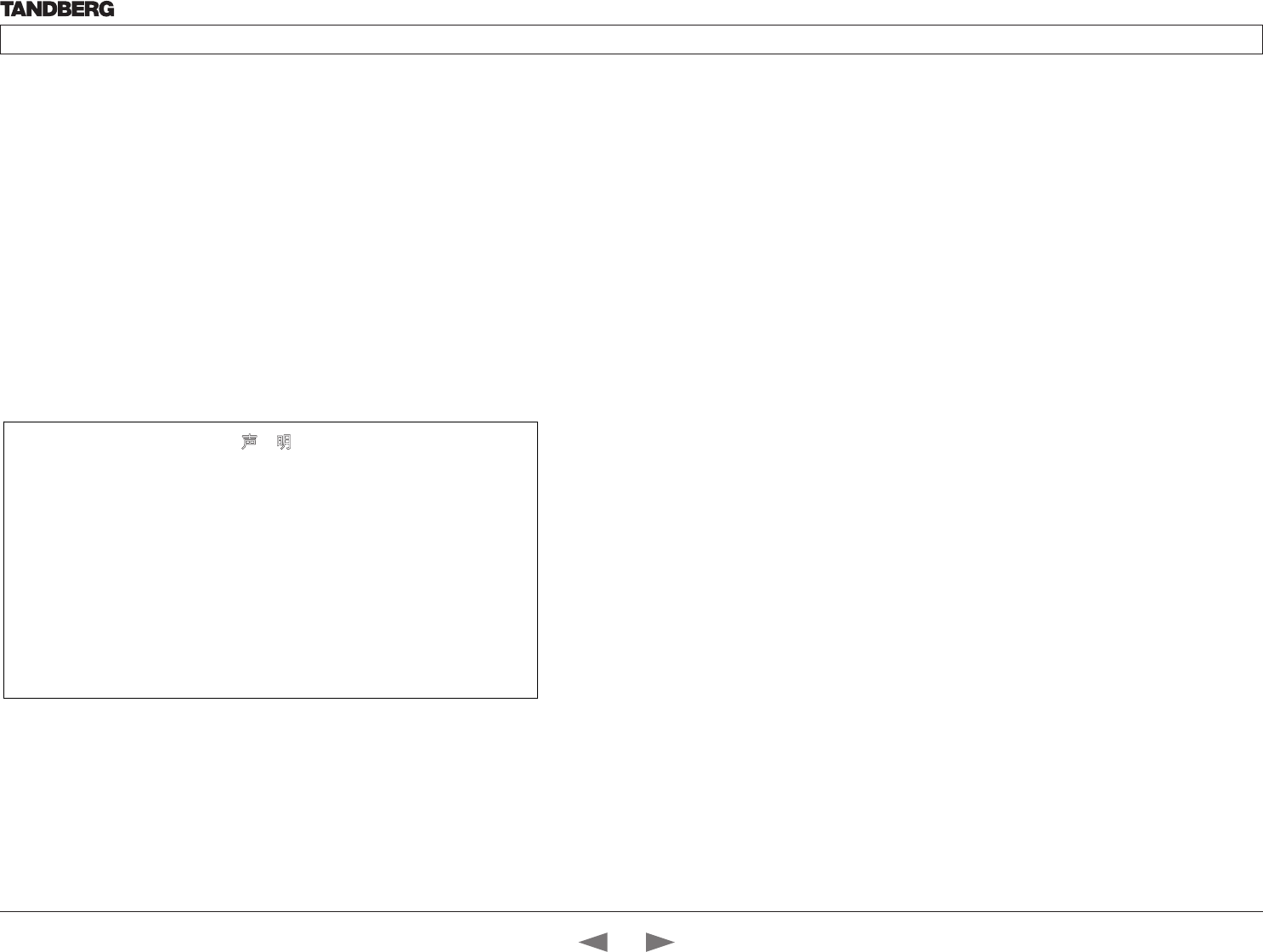
A级声明( A Class product declaration)
本产品为 A级ITE,在其使用说明,铭牌等显著位置中已包含如下内
容的声明(We declare here that the subject product is A Class ITE
product, and the following statement is clearly marked in the user
manual and nameplate :
声 明
此为 A 级产品
,在生活环境中,该产品可能会造成无线电干扰。在这
种情况下,可能需要用户对其干扰采取切实可行的措施。
WARNING:
This is a class A product. In a domestic environment this product may
cause radio interference in which case the user may be required to take
adequate measures.
声明所在位置
Position of the Declaration: nameplate □
User manual □
公司 Company Name:
签字/盖章 Signature/ Stamp:
Contents
Introduction
Getting started
About the menus
The Settings menu
The Settings library
Cameras
Appendices
Contact us
Introduction
D14324.04—DECEMBER 2009 9
Profile series with Codec C60 Administrator Guide
Contents Introduction Getting started About the menus The settings menu Settings Library Cameras Appendices Contact us
Environmental Issues
Thank you for buying a product which contributes
to a reduction in pollution, and thereby helps save
the environment. Our products reduce the need for
travel and transport and thereby reduce pollution.
Our products have either none or few consumable
parts (chemicals, toner, gas, paper).
TANDBERG’s Environmental Policy
Environmental stewardship is important to
TANDBERG’s culture. As a global company with
strong corporate values, TANDBERG is committed
to following international environmental legislation
and designing technologies that help companies,
individuals and communities creatively address
environmental challenges.
TANDBERG’s environmental objectives are to:
• Develop products that reduce energy
consumption, CO2 emissions, and traffic
congestion
• Provide products and services that improve
quality of life for our customers
• Produce products that can be recycled or
disposed of safely at the end of product life
• Comply with all relevant environmental
legislation.
Digital User Guides
TANDBERG is pleased to announce that we have
replaced the printed versions of our user guides
with digital versions available on the TANDBERG
web site: http://www.tandberg.com/docs. The
environmental benefits of this are significant. The
user guides can still be printed locally, whenever
needed.
European Environmental Directives
As a manufacturer of electrical and electronic
equipment TANDBERG is responsible for
compliance with the requirements in the European
Directives 2002/96/EC (WEEE - Waste Electrical
and Electronic Equipment) and 2002/95/EC
(RoHS).
The primary aim of the WEEE Directive and RoHS
Directive is to reduce the impact of disposal of
electrical and electronic equipment at end-of-life.
The WEEE Directive aims to reduce the amount
of waste electrical and electronic equipment sent
for disposal to landfill or incineration by requiring
producers to arrange for collection and recycling.
The RoHS Directive bans the use of certain heavy
metals and brominated flame retardants to reduce
the environmental impact of WEEE which is in
landfill or incinerated.
TANDBERG has implemented necessary process
changes to comply with the European WEEE
Directive (2002/96/EC) and the European RoHS
Directive (2002/95/EC).
Waste Handling
In order to avoid the dissemination of hazardous
substances in our environment and to diminish the
pressure on natural resources, we encourage you
to use the appropriate recycling systems in your
area. Those systems will reuse or recycle most
of the materials of your end of life equipment in a
sound way.
TANDBERG products put on the market after
August 2005 are marked with a crossed-out
wheelie bin symbol that invites you to use
those take-back systems.
Please contact your local supplier, the regional
waste administration or visit our web page http://
www.tandberg.com/recycling if you need more
information on the collection and recycling system
in your area.
Information for Recyclers
As part of compliance with the European
WEEE Directive, TANDBERG provides recycling
information on request for all types of new
equipment put on the market in Europe after
August 13th 2005.
Please contact TANDBERG and provide the
following details for the product for which you
would like to receive recycling information:
• Model number of TANDBERG product
• Your company’s name
• Contact name
• Address
• Telephone number
• E-mail.
Contents
Introduction
Getting started
About the menus
The Settings menu
The Settings library
Cameras
Appendices
Contact us
Introduction
D14324.04—DECEMBER 2009 10
Profile series with Codec C60 Administrator Guide
Contents Introduction Getting started About the menus The settings menu Settings Library Cameras Appendices Contact us
Getting started
Chapter 2
In this chapter...
System overview
Cable configurations
Using the remote control
Initial configurations
Waking up the system
Verify IP address settings
Setting a static IP address
Add the system to the network
Verify your settings
Date and time settings
Menu password
This chapter introduces you to the video
system and gets you up and going.
The guide has been divided into several
chapters, all of which provide different
information. You can access the chapters
directly by clicking on the menu bar at the
top of this page.
Contents
Introduction
Getting started
About the menus
The Settings menu
The Settings library
Cameras
Appendices
Contact us
Getting started
D14324.04—DECEMBER 2009 11
Profile series with Codec C60 Administrator Guide
Contents Introduction Getting started About the menus The settings menu Settings Library Cameras Appendices Contact us
Power cable
Mic cable
PC cable
Ethernet cable
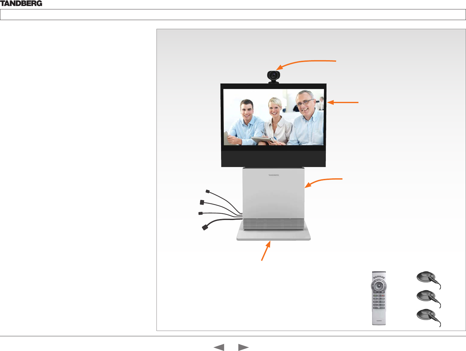
TANDBERG Profile 42”
3 x Microphones
with cables
Remote control
with batteries
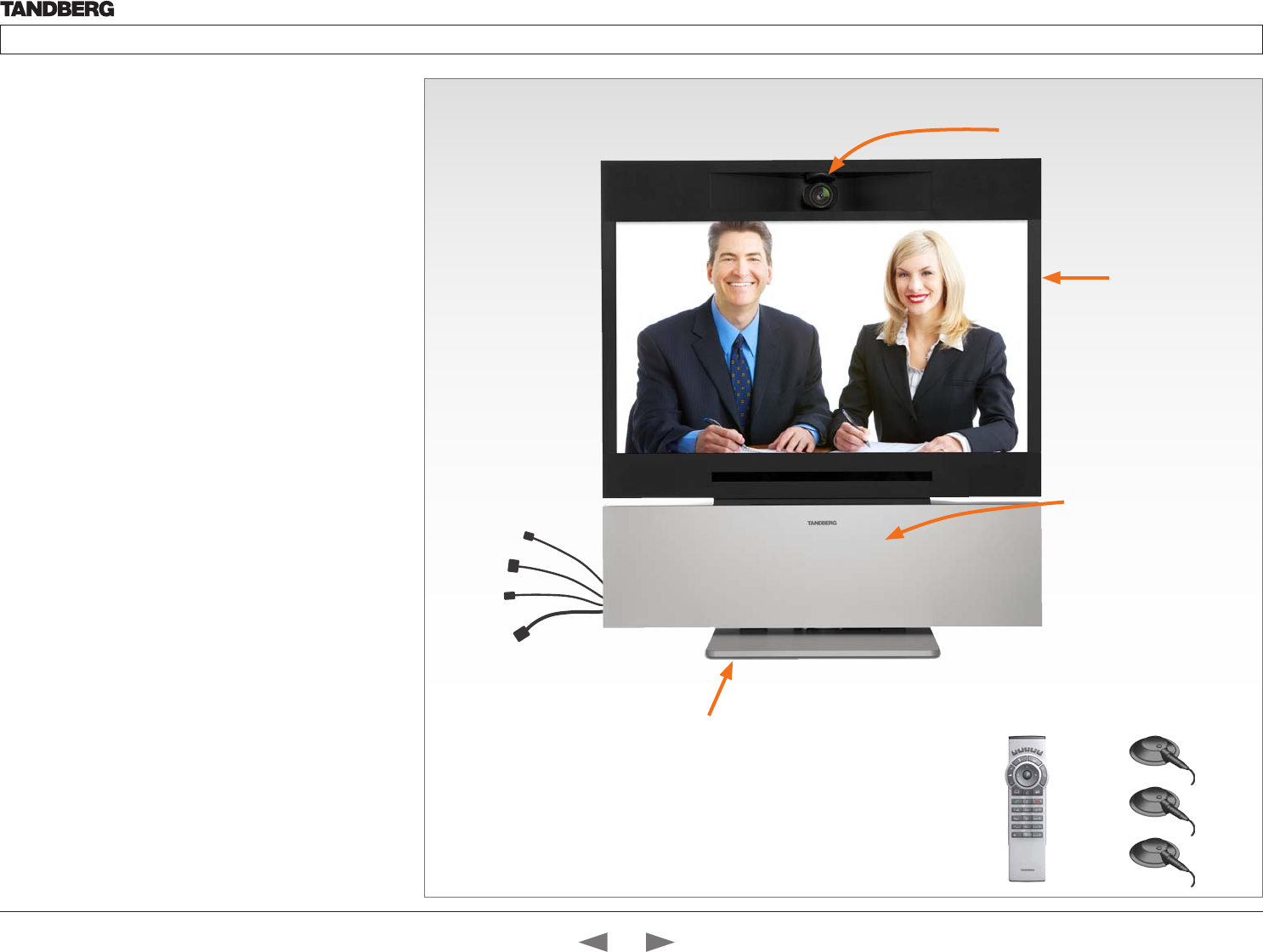
System overview
See the installation sheet for the TANDBERG Profile 42” for
instructions on how to install the system.
Codec C60
• Full HD video
• High resolution data sharing
• Full HD Multisite
• Rich I/O capabilities
PrecisionHD 1080p camera
Full HD Camera designed for visual communication with:
• 12 x optical zoom
• Fast and precise pan, tilt and zoom
Monitor
42” Full HD LCD, 16:9, 1080 x 1920 resolution
Audio module
Wide band audio module supporting:
• 20 kHz AAC-LD
• Full echo canceling
• Stereo
Audio amplifier
Optimized DNAM for TANDBERG Profile providing
crystal clear and natural audio.
Microphones
3 x Microphones
Remote control
• 1 x TANDBERG Remote Control TRC5
• 4 x AAA batteries
Foot stand
1 x Foot stand
• Standalone, wheelbase or wall mounting
In the bottom module:
• Audio amplifier (DNAM)
• TANDBERG Codec C60
PrecisionHD 1080p camera
Monitor 42’’
Full HD LCD
Foot stand (standalone, wheelbase
or wall mounting foot module)
Contents
Introduction
Getting started
About the menus
The Settings menu
The Settings library
Cameras
Appendices
Contact us
Getting started
D14324.04—DECEMBER 2009 12
Profile series with Codec C60 Administrator Guide
Contents Introduction Getting started About the menus The settings menu Settings Library Cameras Appendices Contact us
Power cable
Mic cable
PC cable
Ethernet cable
Foot stand (standalone, wheelbase
or wall mounting foot module)
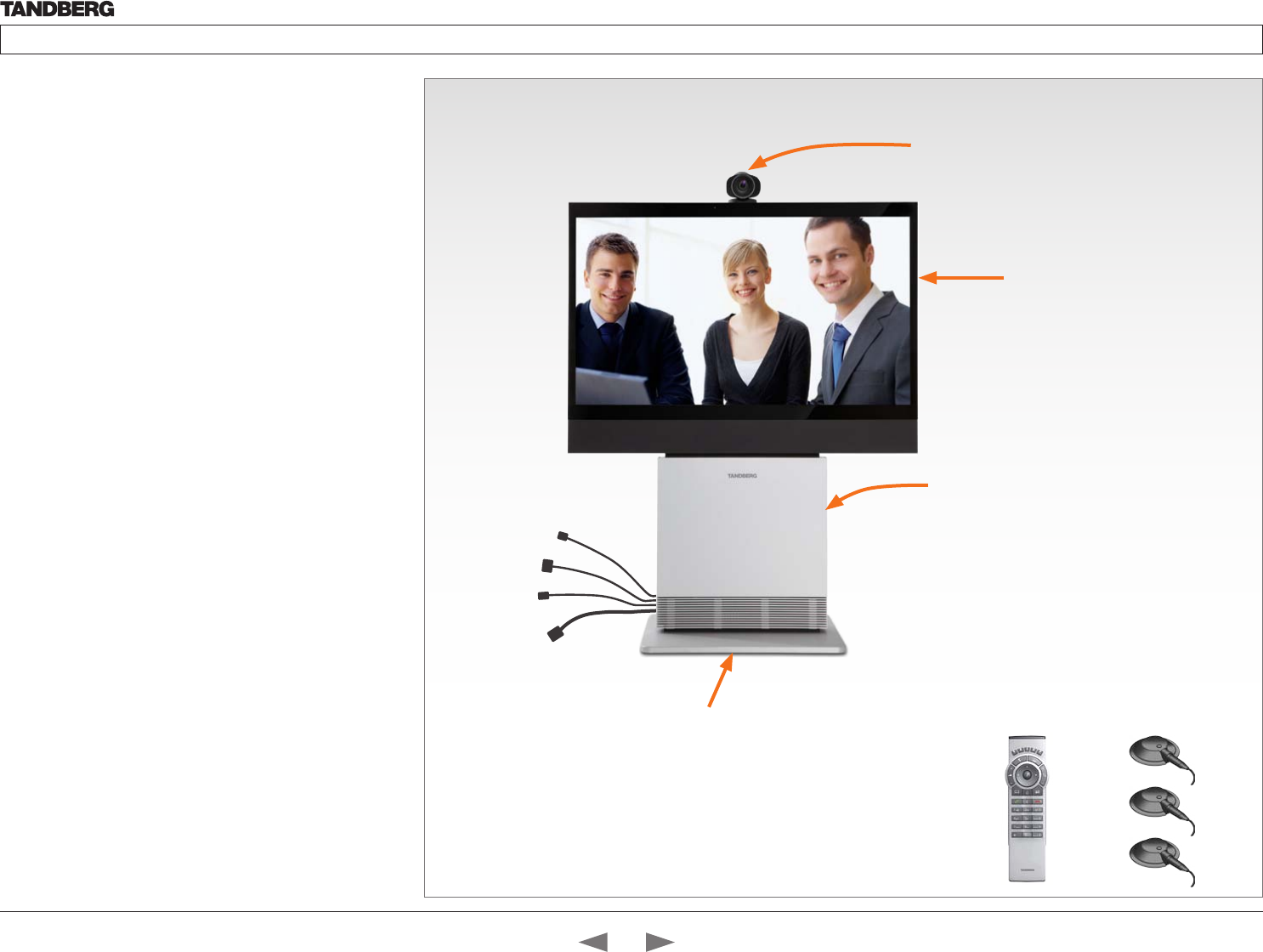
PrecisionHD 1080p camera
Monitor 52’’
Full HD LCD
In the bottom module:
• Audio amplifier (DNAM)
• TANDBERG Codec C60
TANDBERG Profile 52”
3 x Microphones
with cables
Remote control
with batteries
System overview
See the installation sheet for the TANDBERG Profile 52” for
instructions on how to install the system.
Codec C60
• Full HD video
• High resolution data sharing
• Full HD Multisite
• Rich I/O capabilities
PrecisionHD 1080p camera
Full HD Camera designed for visual communication with:
• 12 x optical zoom
• Fast and precise pan, tilt and zoom
Monitor
52” Full HD LCD, 16:9, 1080 x 1920 resolution
Audio module
Wide band audio module supporting:
• 20 kHz AAC-LD
• Full echo canceling
• Stereo
Audio amplifier
Optimized DNAM for TANDBERG Profile providing
crystal clear and natural audio.
Microphones
3 x Microphones
Remote control
• 1 x TANDBERG Remote Control TRC5
• 4 x AAA batteries
Foot stand
1 x Foot stand
• Standalone, wheelbase or wall mounting
Contents
Introduction
Getting started
About the menus
The Settings menu
The Settings library
Cameras
Appendices
Contact us
Getting started
D14324.04—DECEMBER 2009 13
Profile series with Codec C60 Administrator Guide
Contents Introduction Getting started About the menus The settings menu Settings Library Cameras Appendices Contact us
Power cable
Mic cable
PC cable
Ethernet cable
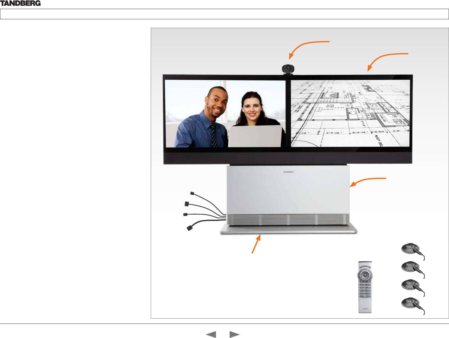
TANDBERG Profile 52” Dual
4 x Microphones
with cables
Remote control
with batteries
System overview
See the installation sheet for the TANDBERG Profile 52” for
instructions on how to install the system.
Codec C60
• Full HD video
• High resolution data sharing
• Full HD Multisite
• Rich I/O capabilities
PrecisionHD 1080p camera
Full HD Camera designed for visual communication with:
• 12 x optical zoom
• Fast and precise pan, tilt and zoom
Dual monitor
Dual 52” Full HD LCD, 16:9, 1080 x 1920 resolution
Audio module
Wide band audio module supporting:
• 20 kHz AAC-LD
• Full echo canceling
• Stereo
Audio amplifier
Optimized DNAM for TANDBERG Profile providing
crystal clear and natural audio.
Microphones
4 x Microphones
Remote control
• 1 x TANDBERG Remote Control TRC5
• 4 x AAA batteries
Foot stand
1 x Foot stand
• Standalone or wall mounting
PrecisionHD 1080p camera
Dual 52’’ monitor
Full HD LCD
In the bottom module:
• Audio amplifier (DNAM)
• TANDBERG Codec C60
Foot stand (standalone or
wall mounting foot module)
Contents
Introduction
Getting started
About the menus
The Settings menu
The Settings library
Cameras
Appendices
Contact us
Getting started
D14324.04—DECEMBER 2009 14
Profile series with Codec C60 Administrator Guide
Contents Introduction Getting started About the menus The settings menu Settings Library Cameras Appendices Contact us
Power cable
Mic cables
PC cable
Ethernet cable
System overview
See the TANDBERG Profile 65” Installation Sheet for instructions of
how to assemble the system.
Codec C60
• Full HD video
• High resolution data sharing
• Full HD Multisite
• Rich I/O capabilities
PrecisionHD 1080p camera
Full HD Camera designed for Visual communication with:
• 12 x optical zoom
• Fast and precise pan, tilt and zoom
Monitor 65”
65” Full HD LCD, 16:9, 1080 x 1920 resolution
Audio module
Wide band audio module supporting:
• 20 kHz AAC-LD
• Full echo canceling
• Stereo
Audio amplifier
Optimized DNAM for TANDBERG Profile 65” providing
crystal clear and natural audio.
Microphones
3 x Microphones
Remote control
• TANDBERG Remote Control TRC5
• 4 x AAA batteries
Foot stand
Foot stand (standalone or wall mounting)
Foot stand (standalone or wall
mounting foot module)
PrecisionHD 1080p camera
Monitor 65”
Full HD LCD
TANDBERG Profile 65”
Remote control
with batteries
In the bottom module:
• Audio amplifier (DNAM)
• TANDBERG Codec C60
3 x Microphones
with cables
Contents
Introduction
Getting started
About the menus
The Settings menu
The Settings library
Cameras
Appendices
Contact us
Getting started
D14324.04—DECEMBER 2009 15
Profile series with Codec C60 Administrator Guide
Contents Introduction Getting started About the menus The settings menu Settings Library Cameras Appendices Contact us
!
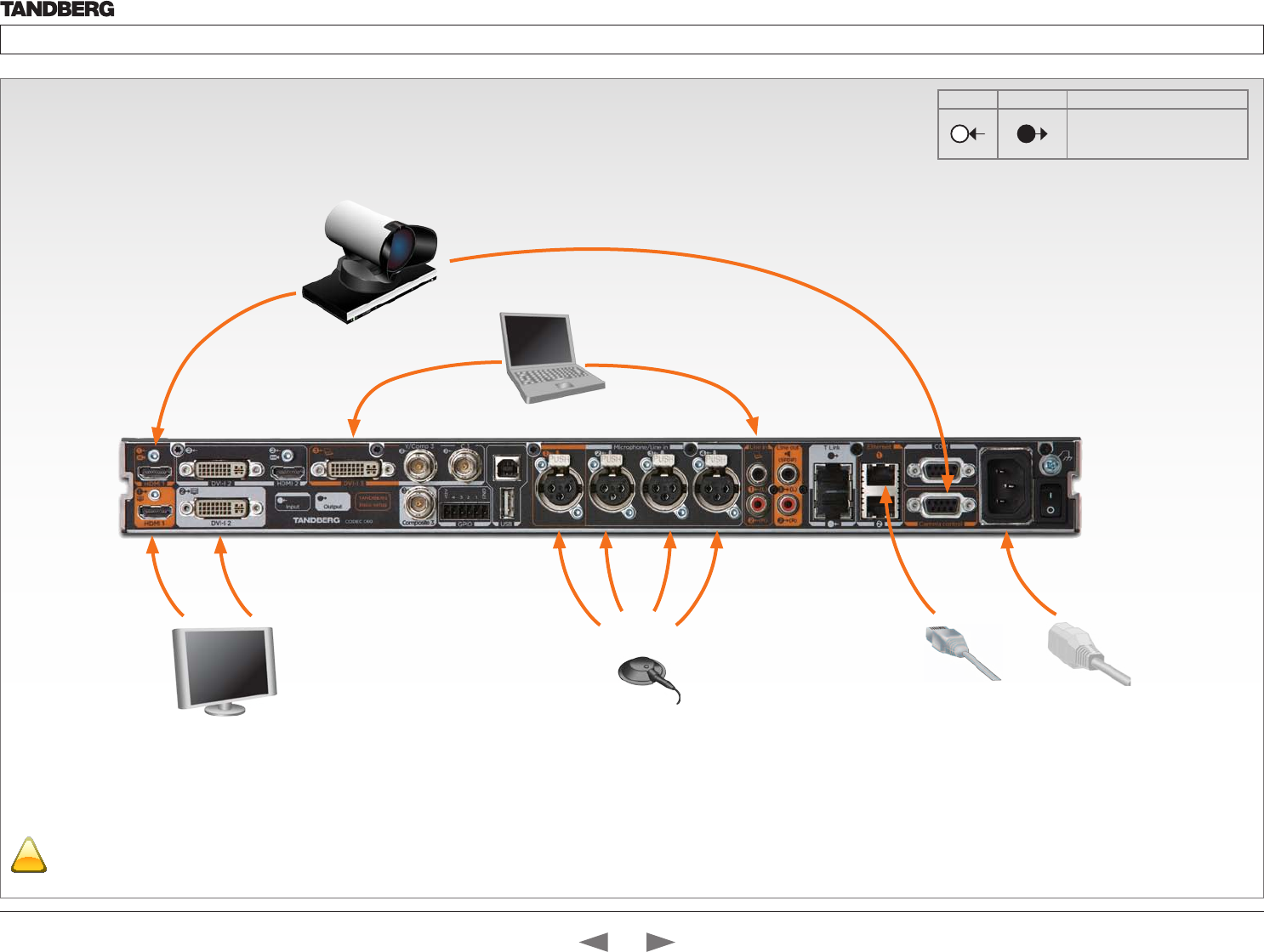
Codec cable configuration
The illustration shows you the basic setup when connecting the monitor, PC,
camera, microphone, LAN and line voltage to the TANDBERG Codec C60.
Make sure the codec has been switched off and
disconnected from the line voltage whenever
connecting or disconnecting other equipment.
Video to the camera
(HDMI to HDMI)
LAN/
Ethernet
Mains Power
Cable
Camera control cable
(RJ45 to DSUB)
PC (audio
to Line In 1)
Profile 42”/52”/65”: Single monitor to DVI-I 2
Profile 52” Dual: Dual monitors to HDMI 1 and DVI-I 2
Microphones
INPUTS OUTPUTS TANDBERG Basic Setup
11
The main connectors for
TANDBERG basic setup
are highlighted in orange.
PC (video
to DVI 3)
Contents
Introduction
Getting started
About the menus
The Settings menu
The Settings library
Cameras
Appendices
Contact us
Getting started
D14324.04—DECEMBER 2009 16
Profile series with Codec C60 Administrator Guide
Contents Introduction Getting started About the menus The settings menu Settings Library Cameras Appendices Contact us
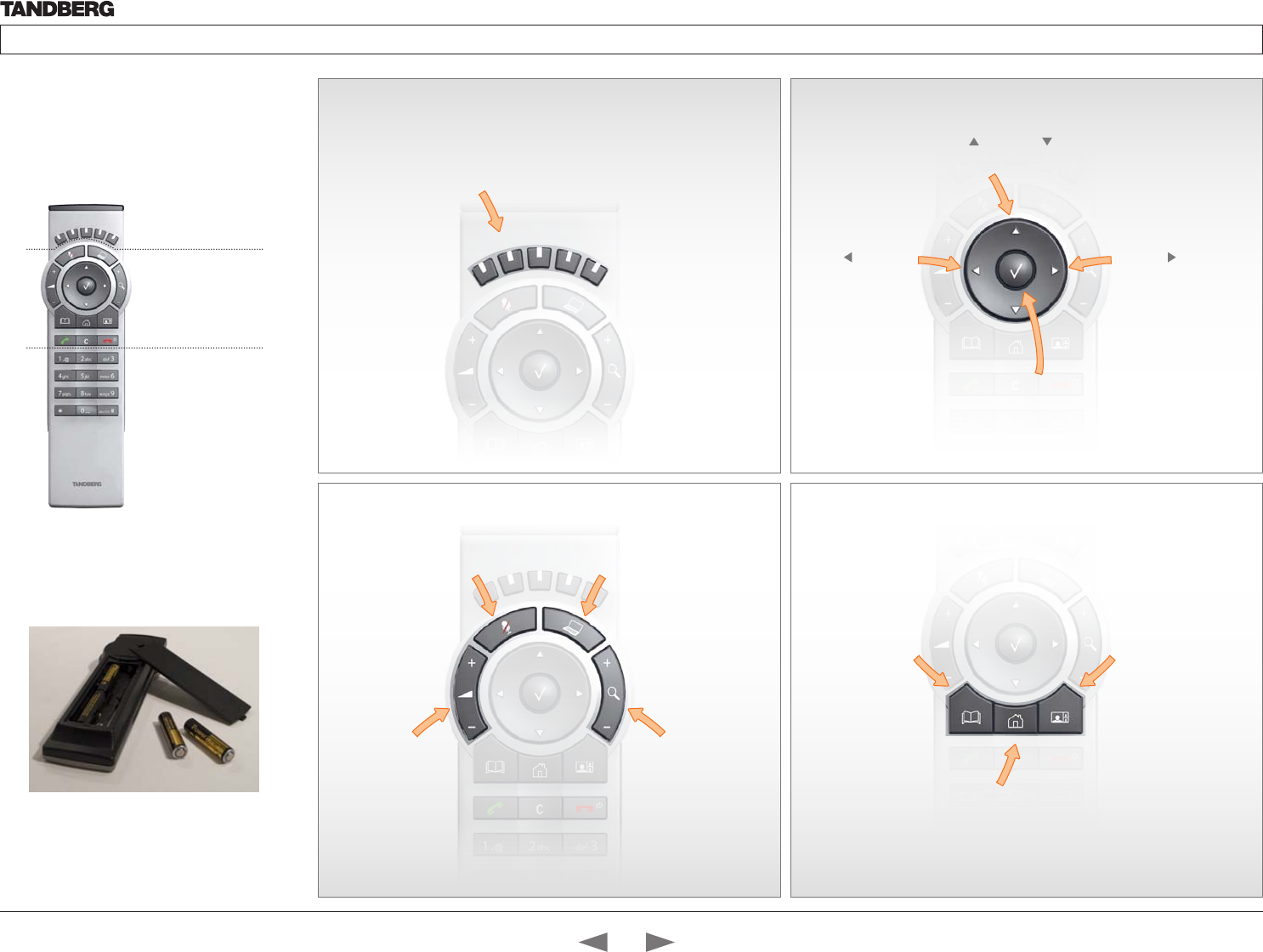
Using the Remote Control
The functions keys
in the upper part of
the remote control
reflects the soft keys
on screen.
... and the middle
part of the remote
control is used to
handle the video
part of the call.
... while the lower
part of the remote
control resembles
very much the
keypad of a mobile
phone
HOME: Press the
Home key to go back
to the main menu.
PHONE BOOK: Press
the Phone Book key to
display the local phone
book.
LAYOUT: Press the Layout
key to display the layout
menu, then select a view
in the menu.
Batteries
Make sure the remote control has
working batteries (4 x AAA batteries).
ARROW UP/DOWN: Use
the up and down
arrow keys to navigate in
the menu.
ARROW LEFT: Press
the left arrow key
to go one step back
in the menu or to
move to the left in a
text field.
ARROW RIGHT: Press
the right arrow key
to expand the selected
menu item or to move
to the right in a text
field.
FUNCTION KEYS: Each key reflects
a soft key on screen and represents
shortcuts and advanced functions.
MICROPHONE: Press the
Microphone key to toggle
the microphones on/off.
VOLUME: Press
the + or – on the
Volume key to adjust
the codec volume.
MUTE: Press the – to
mute an incoming call.
PRESENTATION: Press the
Presentation key to show/hide
a presentation.
ZOOM: Press
the + or – on the Zoom
key to zoom the camera
in and out.
OK/SELECT: Press the OK/
Select key to confirm your
choice or selection.
Contents
Introduction
Getting started
About the menus
The Settings menu
The Settings library
Cameras
Appendices
Contact us
Getting started
D14324.04—DECEMBER 2009 17
Profile series with Codec C60 Administrator Guide
Contents Introduction Getting started About the menus The settings menu Settings Library Cameras Appendices Contact us
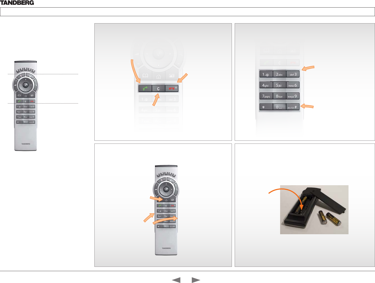
Waking up the system
Press any key on the remote control to wake up the system.
IR sensor range (DIP switch setting)
The IR sensor has a short and long range. Open the battery cover and remove
the batteries to set the DIP switch.
• Short range (1 m): Move the DIP switch down
• Long range: Move the DIP switch up.
ALPHANUMERIC KEYPAD
Use the keypad in the same way as you would
use a cellular phone.
Using the Remote
Control, cont...
The functions keys
in the upper part of
the remote control
reflects the soft keys
on screen.
... and the middle
part of the remote
control is used to
handle the video
part of the call.
... while the lower
part of the remote
control resembles
very much the
keypad of a mobile
phone
Touch the rubber
line sensors along
the sides to wake
up the system
Press the HOME
key to show the
menu on screen The DIP
switch
abc/123 #: Press the # key to
toggle between lower case
characters and numbers.
0-9, a-z, period (.), @, space, *:
Press a key repeatedly to toggle
between the options displayed
on each key.
CALL KEY
INITIATE CALL: Select a name from the Phone book or enter the
name, number or URI and press the Call key to initiate the call.
SHORTCUT TO RECENT CALLS: Use the Call button as a
shortcut to Recent Calls when the Call menu is not visible.
CLEAR: Press the Cancel
key to remove characters
in a text field.
END CALL, STANDBY:
Press the End Call
key to end a call, or
when idle, press and
hold the key to go into
standby mode.
Contents
Introduction
Getting started
About the menus
The Settings menu
The Settings library
Cameras
Appendices
Contact us
Getting started
D14324.04—DECEMBER 2009 18
Profile series with Codec C60 Administrator Guide
Contents Introduction Getting started About the menus The settings menu Settings Library Cameras Appendices Contact us
Waking up the system
If no menu on screen, press Home ( ) on the remote control to show
the menu on screen.
If the system does not show any menu on screen:
1. Make sure the monitor has been turned on
2. Make sure the remote control has the batteries installed
3. Make sure the codec has been turned on
4. If the system has just been turned on, wait a few minutes to allow the
system to startup
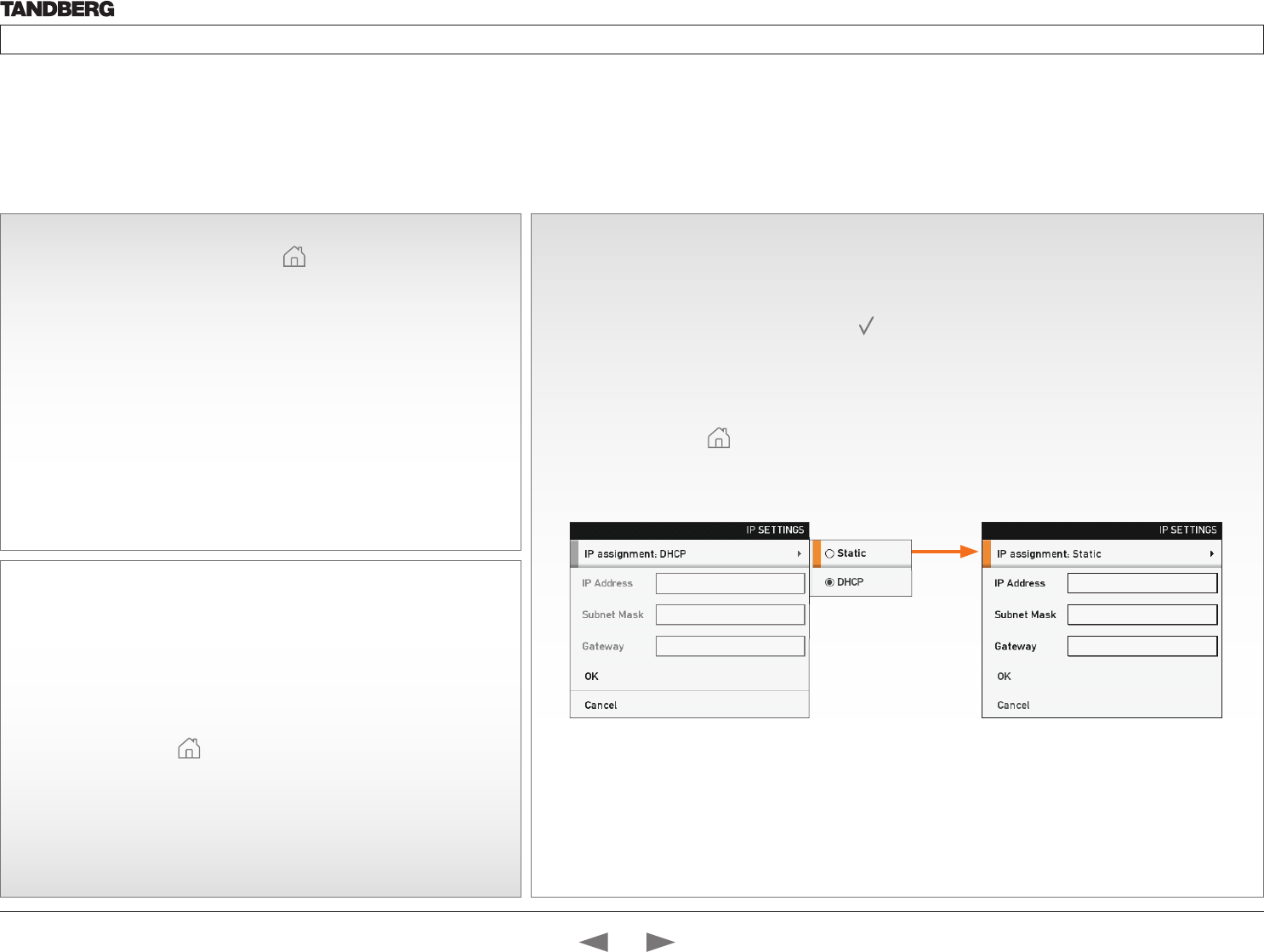
13If you need to set a static IP address
How to set the static IP address:
1. Navigate to Settings > Advanced > IP settings.
2. Set IP Assignment to Static. Press OK ( ) to save the change.
3. Enter the IP Address, Subnet Mask and Gateway address in the address fields. The
sequence is shown below.
4. Navigate to OK to save the changes, or Cancel to leave without saving.
5. Press Home ( ) to exit.
Verify IP address settings
How to go to the System Information page to verify the IP address:
1. Navigate to Settings > System Information to open the System
information page.
2. When the IP address is automatically assigned from a DHCP server, the
network IP address of the codec is shown on the System Information
page.
3. Press Home ( ) to exit.
2
Initial configurations
Before you can start making calls with the system you will need to set the IP address,
add the system to the network and check if the date and time settings needs to be
adjusted. When starting up the system the first time the menu password is not set. But,
when done it is recommended to set a menu password to get access to the Advanced
configuration menu.
Password protection of the Advanced menu
If a menu password has been set you will be asked to enter a password to get access to the Advanced menu. By default, the
menu password is not set when starting up the system for the first time.
After having finished the initial configurations it is recommended to define an menu password.
192.168.1.1
255.255.255.0
192.168.1.1
Contents
Introduction
Getting started
About the menus
The Settings menu
The Settings library
Cameras
Appendices
Contact us
Getting started
D14324.04—DECEMBER 2009 19
Profile series with Codec C60 Administrator Guide
Contents Introduction Getting started About the menus The settings menu Settings Library Cameras Appendices Contact us
firstname.lastname@company.com
4 5
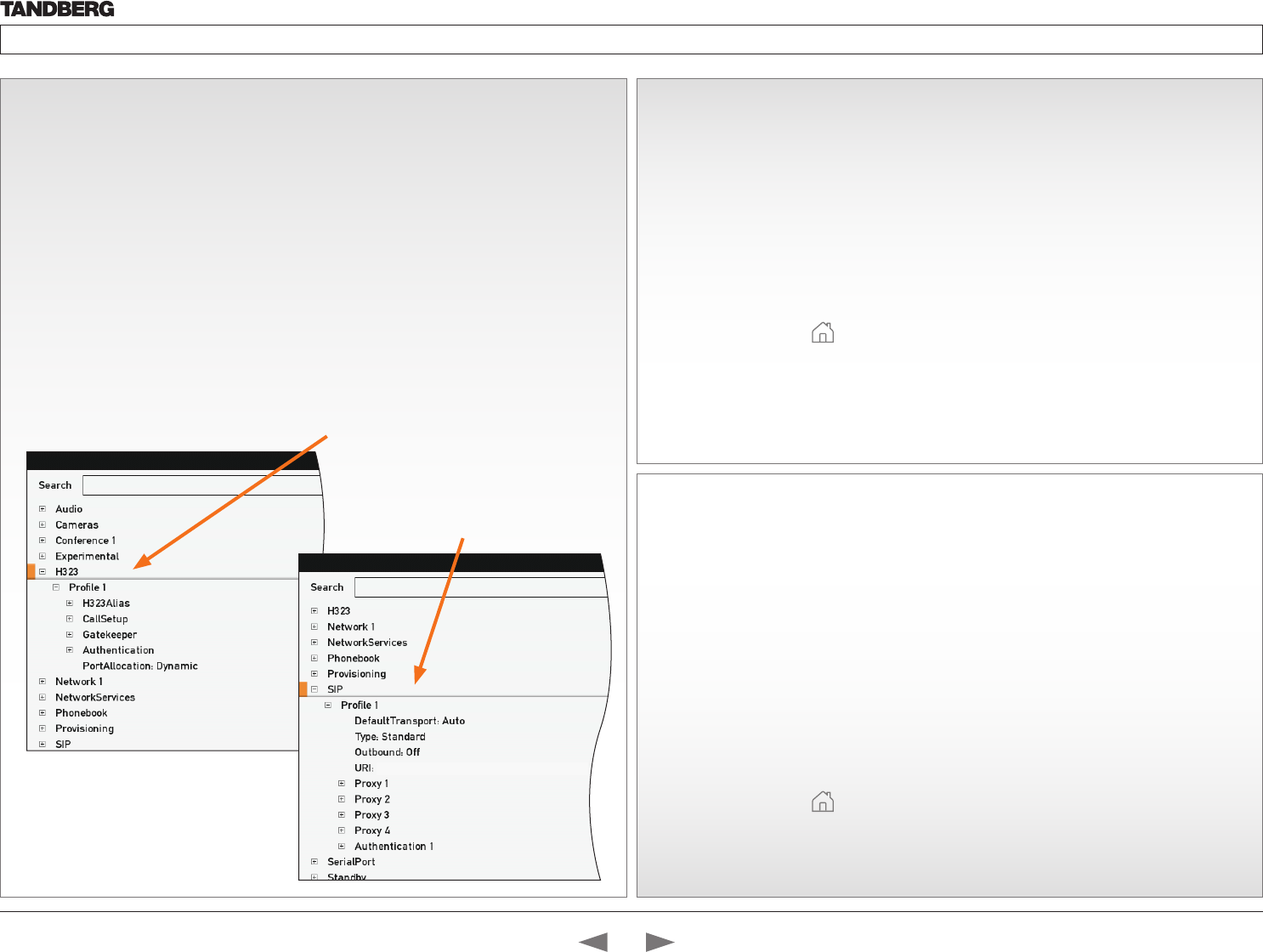
Adding the system to the network
Your service provider should have provided you with the information you need to
get online.
• For H.323 type of communication, this will include such things as system
name, H.323 alias, gatekeeper address, etc.
• For SIP type of communication, similar type of information will be supplied.
• For networks administrated through TMS (TANDBERG Management Suite),
your TMS administrator will be able to assist you when configuring.
The H.323 and SIP profiles are configured from the Advanced configurations
menu:
Navigate to Settings > Advanced > Advanced configuration and make a search
for H323 or SIP, or select H323 > Profile 1 or SIP > Profile 1 from the menu
• Expand the items in need of modification and enter the information supplied by
your service provider.
Verify your settings
We strongly recommend that you verify the settings by inspecting the System
Information list.
You do this by accessing the System Information in the same way as you did
when you verified you IP address setting.
1. Navigate to Settings > System Information
2. Verify the previous configurations.
• If you successfully registered to a Gatekeeper the Status will show
Registered. If the registration failed the Status will show Not registered.
• If you successfully registered to a SIP server the Status will show
Registered. If the registration failed the Status will show Not registered.
3. Press Home ( ) to exit.
6Adjusting the date and time settings
Verify the date and time to see if the date and time settings need to be adjusted.
The date and time is located in the upper right corner on screen.
How to adjust the date and time settings:
1. Navigate to Settings > Date and time
2. When Set date and time is set to Auto there will be an automatic update of
the date and time settings. If you want to manually adjust the date and time
settings, select Manual and enter the Day, Month, Year and Time. After
having adjusted the settings manually you can set the Set date and time
back to Auto for automatic update.
3. Select the appropriate Time zone from the list of GMT time zones.
4. Select the appropriate Date format from the list.
5. Select the appropriate Time format from the list.
6. Press Home ( ) to exit.
Configure the H.323 Profile in the
Advanced configuration menu
Configure the SIP Profile in the
Advanced configuration menu
ADVANCED CONFIGURATION
ADVANCED CONFIGURATION
Contents
Introduction
Getting started
About the menus
The Settings menu
The Settings library
Cameras
Appendices
Contact us
Getting started
D14324.04—DECEMBER 2009 20
Profile series with Codec C60 Administrator Guide
Contents Introduction Getting started About the menus The settings menu Settings Library Cameras Appendices Contact us
7Setting a menu password
It is highly recommended to define a password to access the Advanced menus.
Changing these settings may affect the behavior of the system and should be
done by the system administrator.
NOTE! The menu password will only apply to the Advanced menu. The codec and
the web interface can be password protected with an administrator password.
See the Password protection section in the Appendices for a detailed description.
NOTE! When you define or change a password make sure you save a copy of the
password in a safe place.
How to set the menu password
Navigate to Settings > Advanced > Change password
1. On the remote control, press the # key to toggle between lower or upper case
characters and numbers: abc/ABC/123
2. Enter the menu password. The password you enter is hidden, as each
character is replaced with a star (*).
3. Navigate to Save to save the changes, or Cancel to leave without saving.
4. Press Home ( ) to exit.
Contents
Introduction
Getting started
About the menus
The Settings menu
The Settings library
Cameras
Appendices
Contact us
Getting started
D14324.04—DECEMBER 2009 21
Profile series with Codec C60 Administrator Guide
Contents Introduction Getting started About the menus The settings menu Settings Library Cameras Appendices Contact us
About the menus
In this chapter...
Explains the menu system
Chapter 3
Contents
Introduction
Getting started
About the menus
The Settings menu
The Settings library
Cameras
Appendices
Contact us
About the menus
D14324.04—DECEMBER 2009 22
Profile series with Codec C60 Administrator Guide
Contents Introduction Getting started About the menus The settings menu Settings Library Cameras Appendices Contact us
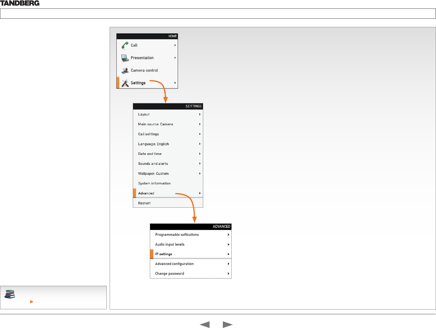
About the menus
The menu path to the Advanced configuration
menu:
1. The Home menu
2. The Settings menu
3. The Advanced menu
4. The Advanced configuration menu
The user documentation structure
• The Administrator Guide explains all settings
found in the Advanced and Advanced
configuration menus.
• The User Guide explains how to make use
of the video system, which includes making
calls and explaining about the settings found
in the Home menu, Settings menu and
the Programmable softbuttons from the
Advanced menu.
Navigating in the menus
Use the remote control to navigate in the menus:
• Use the arrows down/up to select a menu item
• Use the arrow right to expand the selection
• Use the arrow left to go one step back
Changing a value
• Select a value from a drop down list and press
the OK button to save, or press the left arrow to
leave without saving.
• Enter a value/text in a value/text field. Press
Save to save the change or Cancel to leave
without saving.
Download the TANDBERG user guides from
the web site.
Go to: http://www.tandberg.com/docs
The Home menu
The Home menu is explained in the TANDBERG Profile User Guide.
• Call: Menu for making calls.
• Presentation: Select a presentation source.
• Camera control: Control the camera settings.
• Settings: Configure the system.
The Settings menu
The Settings menu is explained in the TANDBERG Profile User Guide.
• Layout: Select screen layout, including selfview.
• Main source: Select the main video source.
• Call settings: Configure the default bit rate and auto answer settings.
• Language: Select the preferred menu language.
• Date and time: Configure date and time settings.
• Sounds and alerts: Select a ring tone, the ring tone volume and key tone.
• Wallpaper: Select the background picture on screen
• System Information: See an overview of the system configurations
• Advanced: Configure the advanced settings.
• Restart: Select this option to restart the system.
The Advanced menu
NOTE! The Advanced menu can be password protected with a menu password.
• Programmable soft buttons: User defined soft-buttons for selecting main video source,
camera presets or speed dial.
• Audio input levels: Lets you see a visual overview of the audio input levels.
• IP settings: Lets you configure the IP settings.
• Advanced configuration: Lets you configure the system settings.
• Change password: Lets you change the menu password.
Contents
Introduction
Getting started
About the menus
The Settings menu
The Settings library
Cameras
Appendices
Contact us
About the menus

D14324.04—DECEMBER 2009 23
Profile series with Codec C60 Administrator Guide
Contents Introduction Getting started About the menus The settings menu Settings Library Cameras Appendices Contact us
The system settings menus
In this chapter...
Explaining the system
settings menus
Chapter 4
Contents
Introduction
Getting started
About the menus
The Settings menu
The Settings library
Cameras
Appendices
Contact us
The settings menu
D14324.04—DECEMBER 2009 24
Profile series with Codec C60 Administrator Guide
Contents Introduction Getting started About the menus The settings menu Settings Library Cameras Appendices Contact us
The Advanced menus
Changes in the Advanced menus settings may
affect the behavior of the system and should be
configured by the system administrator.
How to change a value
• Select a value from a drop down list and press
the OK button to save, or press the left arrow to
leave without saving.
• Enter a value/text in a value/text field. Press
Save to save the change or Cancel to leave
without saving.
Description of each setting
Each of the settings in the Advanced configuration
menu is explained in the Settings library section.
Press the Settings library in the menu on top of
the page to go to this section.
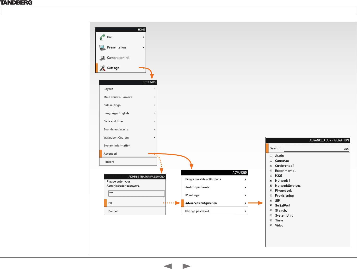
The Advanced menu can be password
protected. If so, type in the password and
press OK to proceed or Cancel to go
back to the Settings menu.
Contents
Introduction
Getting started
About the menus
The Settings menu
The Settings library
Cameras
Appendices
Contact us
The settings menu
D14324.04—DECEMBER 2009 25
Profile series with Codec C60 Administrator Guide
Contents Introduction Getting started About the menus The settings menu Settings Library Cameras Appendices Contact us
The Advanced
configuration menu
The Advanced configuration menu contains all the
system settings, included the IP settings which also
are available in the Advanced menu.
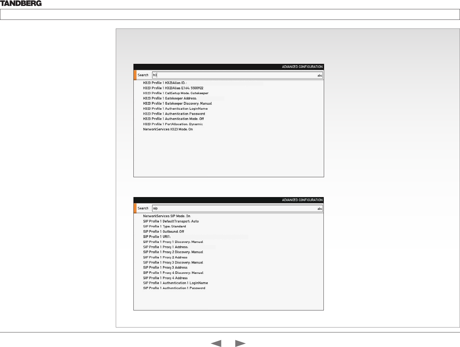
The search functionality
On the remote control, press the # key to toggle
between lower or upper case characters and
numbers: abc/ABC/123
When searching for words like “H323”, “SIP” or
“key”, all settings with these characters in the name
will be listed.
• Search: Enter the as many characters as
needed until the setting you are searching for
displays in the list.
• Refine the search: Add or remove characters
until you get the desired result.
• Clear: Remove all characters to return to the
main view.
Search
Enter the as many characters as needed, until the setting you are searching for displays in the list.
Example 1: Search for “sip” to see all the SIP settings.
Example 2: Search for H323. In this case it is sufficient to enter “h3” to display all the H323 settings.
firstname.lastname@company.com
192.168.10.1
firstname.lastname@company.com
192.168.10.1
Contents
Introduction
Getting started
About the menus
The Settings menu
The Settings library
Cameras
Appendices
Contact us
The settings menu
D14324.04—DECEMBER 2009 26
Profile series with Codec C60 Administrator Guide
Contents Introduction Getting started About the menus The settings menu Settings Library Cameras Appendices Contact us
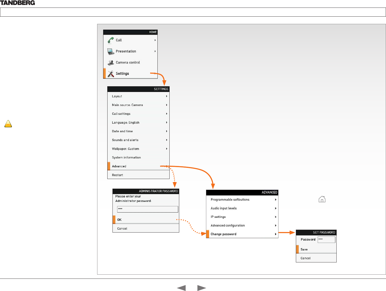
The Advanced menu
How to change the menu password
If a menu password has been set you will be asked
to enter a password to get access to the Advanced
menu.
When turning on the system for the first time, the
password is not set.
NOTE! The menu password will only apply to the
Advanced menu. The codec and the web interface
can be password protected with an administrator
password. See the Password protection section in
the Appendices for a detailed description.
!
When you define or change a password
make sure you save a copy of the password
in a safe place.
Setting a menu password
1. On the remote control, press the # key
to toggle between lower or upper case
characters and numbers: abc/ABC/123
2. Enter the password. The password you
enter is hidden, and each character is
replaced with a star (*).
3. Press Save to save the changes, or
Cancel to leave without saving.
4. Press Home ( ) to exit.
The Advanced menu can be password
protected. If so, type in the password and
press OK to proceed or Cancel to go
back to the Settings menu
Contents
Introduction
Getting started
About the menus
The Settings menu
The Settings library
Cameras
Appendices
Contact us
The settings menu

D14324.04—DECEMBER 2009 27
Profile series with Codec C60 Administrator Guide
Contents Introduction Getting started About the menus The settings menu Settings Library Cameras Appendices Contact us
In this chapter...
Audio
Cameras
Conference
H323 Profile
Network
Network Services
Phone Book Server
Provisioning
Serial Port
SIP Profile
Standby
System Unit
Video
Experimental
Chapter 5
This chapter gives a detailed description of
the advanced system settings
The advanced settings defines the system
settings and are structured in a hierarchy,
making up a database of system settings.
Changes in the system settings may affect
the system and should be done by the
system administrator
The system settings library
Contents
Introduction
Getting started
About the menus
The Settings menu
The Settings library
Cameras
Appendices
Contact us
The Settings library
D14324.04—DECEMBER 2009 28
Profile series with Codec C60 Administrator Guide
Contents Introduction Getting started About the menus The settings menu Settings Library Cameras Appendices Contact us
Audio Input HDMI [2..2] Level: <-24..0>
Defines the input level of HDMI input 2 in steps of 1dB from -24 dB to 0 dB.
See the Audio Level tables in the Codec C60 System Integrators Guide for a complete overview of the menu
values represented in dB.
Range: -24 to 0 dB
Example: Audio Input HDMI 3 Level: 0
Audio Input HDMI [2..2] Mode: <On/Off>
Determines whether or not the two audio channels on the HDMI 2 input should be enabled.
On: Set to On to enable the audio channels on the HDMI 2 input.
Off: Set to Off to disable the audio channels on the HDMI 2 input.
Example: Audio Input HDMI 2 Mode: On
Audio Input Line [1..2] Channel: <Left/Right/Mono>
Defines whether the Audio Line input is a mono signal or part of a multichannel signal.
Left: The Audio Line input signal is the left channel of a stereo signal.
Right: The Audio Line input signal is the right channel of a stereo signal.
Mono: The Audio Line input signal is a mono signal.
Example: Audio Input 1 Channel: Left
Audio Input Line [1..2] Level: <0..24>
Defines the input level of each Line input in steps of 1dB from 0dB to 24 dB. Addresses the specific Audio
Line input.
See the Audio Level tabels in the Codec C60 System Integrators Guide for a complete overview of the menu
values represented in dB.
Range: 0 to 24 dB
Example: Audio Input Line 1 Level: 10
Description of the System settings
In the following pages you will find a complete list of the system settings. The examples shows either the
default value or an example of a value.
All specifications are subject to change without prior notice.
We recommend you visit the TANDBERG web site regularly for updated versions of the manual.
Go to: http://www.tandberg.com/docs
Audio Input Line [1..2] LoopSuppression: <Off>
Loop suppression detects whether a delayed signal loop is present from an audio Line output to an audio
Line input on the codec. If a loop is detected, this unwanted feedback is suppressed.
On: Set to On to activate Loop Suppression.
Off: Set to Off to deactivate Loop Suppression. Note! Codec C60 does currently not support Loop
Suppression, hence Loop Suppression can be set to Off only.
Example: Audio Input Line 1 LoopSuppression: Off
Audio Input Line [1..2] Mode: <On/Off>
Determines whether or not an Audio Line input is enabled. Addresses the specific Audio Line input.
On: Set to On to enable the Audio Line input.
Off: Set to Off to disable the Audio Line input.
Example: Audio Input Line 1 Mode: On
Audio Input Microphone [1..4] EchoControl Mode: <On/Off>
The echo canceller continuously adjusts itself to the audio characteristics of the room and compensate for
any changes it detects in the audio environment. If the changes in the audio conditions are very significant
the echo canceller may take a second or two to re-adjust. Addresses the specific microphone.
On: Echo Control is normally set to On to prevent the far end from hearing their own audio. Once selected,
echo cancellation is active at all times.
Off: Echo Control should be switched Off if external echo cancellation or playback equipment is used.
Example: Audio Input Microphone 1 EchoControl Mode: On
Audio Input Microphone [1..4] EchoControl NoiseReduction: <On/Off>
The system has a built-in noise reduction which reduces constant background noise (e.g. noise from air-
conditioning systems, cooling fans etc.). In addition, a high pass filter (Humfilter) reduces very low frequency
noise. Requires the Echo Control Mode to be enabled for the specified microphone. Addresses the specific
microphone.
On: The Noice Reduction should be set to On in the presence of low frequency noise.
Off: Turns Noise Reduction Off for the specified microphone input.
Example: Audio Input Microphone 1 EchoControl NoiseReduction: On
Audio Input Microphone [1..4] Level: <0..24>
Defines the input level of each microphone in steps of 1dB from -24 dB to 0 dB. Addresses the specific
microphone.
See the Audio Level tables in the Codec C60 System Integrators Guide for a complete overview of the menu
values represented in dB.
Range: 0 to 24 dB
Example: Audio Input Microphone 1 Level: 14
The Audio settings
Contents
Introduction
Getting started
About the menus
The Settings menu
The Settings library
Cameras
Appendices
Contact us
The Settings library
D14324.04—DECEMBER 2009 29
Profile series with Codec C60 Administrator Guide
Contents Introduction Getting started About the menus The settings menu Settings Library Cameras Appendices Contact us
Audio Input Microphone [1..4] Mode: <On/Off>
Determines whether or not a microphone input is enabled. Addresses the specific microphone input.
On: Set to On to enable the microphone input.
Off: Set to Off to disable the microphone input.
Example: Audio Input Microphone 1 Mode: On
Audio Input Microphone [1..4] Type: <Microphone/Line>
The microphone inputs are intended for electret type microphones. The microphone input can be set to line
or microphone mode. Addresses the specific microphone.
Microphone: 48 V Phantom voltage and pre-amplification is On
Line: Select Line when you have a standard balanced line input. The phantom voltage and pre-amplification
is Off.
Example: Audio Input Microphone 1 Type: Line
Audio Output HDMI [1..1] Level: <-24..0>
Defines the output level of HDMI output 1 in steps of 1 dB from -24 dB to 0 dB.
See the Audio Level tables in the Codec C60 System Integrators Guide for a complete overview of the menu
values represented in dB.
Range: -24 to 0 dB
Example: Audio Output HDMI 1 Level: 0
Audio Output HDMI [1..1] Mode: <On/Off>
Determines whether or not the audio channel on the HDMI output should be enabled.
On: Set to On to enable the audio channel on the HDMI 1 or HDMI 3 output.
Off: Set to On to disable the audio channel on the HDMI 1 or HDMI 3 output.
Example: Audio Output HDMI 1 mode: On
Audio Output Line [1..2] Channel: <Left/Right/Mono>
Defines whether the Audio Line output is a mono signal or part of a multichannel signal.
Left: The Audio Line output signal is the left channel of a stereo signal.
Right: The Audio Line output signal is the right channel of a stereo signal.
Mono: The Audio Line output signal is a mono signal.
Example: Audio Output Line 1 Channel: Left
Audio Output Line [1..2] Level: <-24..0>
Defines the output level of the specified Audio Output Line in steps of 1 dB from -24 dB to 0 dB. Addresses
the specific Audio Line output connector.
See the Audio Level tables in the Codec C60 System Integrator Guide for a complete overview of the menu
values represented in dB.
Range: -24 to 0 dB
Example: Audio Output Line 1 Level: -10
Audio Output Line [1..2] Mode: <On/Off>
Determines whether or not an Audio Line output is enabled. Addresses the specific Audio Line output.
On: Set to On to enable the Audio Line output.
Off: Set to Off to disable the Audio Line output.
Example: Audio Output Line 1 Mode: On
Audio Output Line [1] Type: <Auto/SPDIF>
Determines if the Audio Line output is an analog or digital type output.
Auto: If a TANDBERG Digital NAM is detected then SPDIF mode will be selected, otherwise analog mode
will be selected.
SPDIF: Set to SPDIF when you want the Audio Line 1 output to be in digital mode.
Example: Audio Output Line 1 Type: Auto
Audio Output Line [2] Type: <Analog>
Applies to Line 2: This is an analog output.
Example: Audio Output Line 1 Type: Analog
Audio SoundsAndAlerts KeyTones Mode: <On/Off>
The system can produce a sound every time a key on the remote control is pressed.
On: There will be a sound indicator when pressing keys on the remote control.
Off: The key tone on the remote control is switched off.
Example: Audio SoundsAndAlerts KeyTones Mode: Off
Audio SoundsAndAlerts RingTone: <Marbles/IceCrystals/Polaris/Alert/Discrete/Fantasy/
Jazz/Nordic/Echo/Rhythmic>
Selects the ringtone for incoming calls.
Range: Select a tone from the list of ringtones.
Example: Audio SoundsAndAlerts RingTone: Jazz
The Audio settings, continued... The Audio settings, continued...
Contents
Introduction
Getting started
About the menus
The Settings menu
The Settings library
Cameras
Appendices
Contact us
The Settings library
D14324.04—DECEMBER 2009 30
Profile series with Codec C60 Administrator Guide
Contents Introduction Getting started About the menus The settings menu Settings Library Cameras Appendices Contact us
Audio SoundsAndAlerts RingVolume: <0..100>
Sets the ring tone volume[0-100] for an incoming call in steps of 0.5dB from -34.5dB to 15dB. Volume 0 =
Off.
Example: Audio SoundsAndAlerts RingVolume: 50
Audio Volume: <0..100>
Sets the volume level [0-100] on the loudspeaker output in steps of 0.5dB from -34.5dB to 15dB. Volume 0
= Off.
Example: Audio Volume: 70
Cameras Camera [1..7] Flip: <On/Off>
Applies to cameras which supports Flip mode. Enables the video on screen to be flipped upside down.
Addresses the specific camera. Since TANDBERG PrecisionHD 1080p camera auto-detects if the camera is
mounted upside down, the flip mode is not necessary to use for this camera.
On: When set to On the video on screen is flipped. This setting is used with cameras that can be mounted
upside down, but cannot auto detect that the camera is mounted upside down.
Off: Set to Off to display the video on screen the normal way.
Example: Cameras Camera 1 Flip: Off
Cameras Camera [1..7] Focus Mode: <Auto/Manual>
Determines whether the camera should be in auto focus or manual focus mode. Addresses the specific
camera.
Auto: When set to Auto the focus will be updated throughout the call. When moving the camera, the system
will use auto focus for a few seconds to set the right focus of the new camera position. After a few seconds
auto focus is turned off to prevent continuous focus adjustments of the camera.
Manual: If set to Manual the focus is adjusted manually.
Example: Cameras Camera 1 Focus Mode: Auto
Cameras Camera [1..7] Gamma Level: <0..7>
By setting the Gamma Level you can select which gamma correction table to use. This setting may be useful
in difficult lighting conditions, where changes to the the brightness setting does not provide satisfactory
results. Requires the Gamma Mode to be set to Manual. Addresses the specific camera.
Range: 0-7
Example: Cameras Camera 1 Gamma Level: 0
Cameras Camera [1..7] Gamma Mode: <Auto/Manual>
Applies to cameras which supports Gamma mode. The Gamma Mode setting enables for gamma
corrections. Gamma describes the nonlinear relationship between image pixels and monitor brightness.
Addresses the specific camera. The TANDBERG PrecisionHD 1080p camera do not need Gamma Mode.
The TANDBERG PrecisionHD 720p camera do support Gamma Mode.
Auto: Auto is the default and the recommended setting.
Manual: In severe light conditions, you may switch mode to manual and specify explicitly which gamma
table to use by setting the Gamma Level.
Example: Cameras Camera 1 Gamma Mode: Auto
The Camera settings
Cameras Camera [1..7] Backlight: <On/Off>
Backlight is used to compensate for lights shining directly at the camera (usually the sun entering the
window) to avoid a too dark image from the room. Addresses the specific camera.
On: Set to On to turn on the backlight compensation.
Off: Set to Off to turn the backlight compensation off.
Example: Cameras Camera 1 Backlight: Off
Cameras Camera [1..7] Brightness Level: <1..31>
Define the Brightness Level for the camera. Requires the Brightness Mode to be set to manual. Addresses
the specific camera.
Range: 1-31
Example: Cameras Camera 1 Brightness Level: 1
Cameras Camera [1..7] Brightness Mode: <Auto/Manual>
Define whether to control the camera brightness manually or to have it automatically adjusted by the system.
Addresses the specific camera.
Auto: When set to Auto, the camera brightness is automatically set by the system.
Manual: Set to Manual to enable manual control of the camera brightness, e.g. the level of the brightness
level setting will be used for the camera.
Example: Cameras Camera 1 Brightness Mode: Auto
The Audio settings, continued... The Camera settings, continued...
Contents
Introduction
Getting started
About the menus
The Settings menu
The Settings library
Cameras
Appendices
Contact us
The Settings library
D14324.04—DECEMBER 2009 31
Profile series with Codec C60 Administrator Guide
Contents Introduction Getting started About the menus The settings menu Settings Library Cameras Appendices Contact us
Cameras Camera [1..7] IrSensor: <On/Off>
The Camera IR setting determines whether the infrared receiver at the camera should be enabled or not.
The IR sensor LED is located in the front of the camera and flickers when the IR sensor is activated from the
remote control. Addresses the specific camera.
On: Set to On to enable the IR sensor on the camera.
Off: Set to Off to disable the IR sensor on the camera.
Example: Cameras Camera 1 IrSensor: On
Cameras Camera [1..7] Mirror: <On/Off>
The Mirror mode makes it possible to reverse the the video on screen. Normally you will see yourself in the
same view as other people sees you. With mirror enabled the experience will be like looking at yourself in a
mirror. Addresses the specific camera.
On: Set to On to see the selfview in mirror mode, e.g. the selfview is reversed and the experience of selfview
is as seeing yourself in a mirror.
Off: Set to Off to see the selfview in normal mode, e.g. the experience of selfview is as seeing yourself as
other people see you.
Example: Cameras Camera 1 Mirror: Off
Cameras Camera [1..7] Whitebalance Level: <1..16>
Specify which camera to control. Define the Whitebalance Level for the camera. Requires the Whitebalance
Mode to be set to manual. Addresses the specific camera.
Range: 1-16
Example: Cameras Camera 1 Whitebalance Level: 1
Cameras Camera [1..7] Whitebalance Mode: <Auto/Manual>
Define whether to control the camera whitebalance manually or to have it automatically adjusted by the
system. Addresses the specific camera.
Auto: When set to Auto, the camera will continuously adjust the whitebalance depending on the camera
view.
Manual: Set to Manual to enable manual control of the camera whitebalance, e.g. the level of the
whitebalance level setting will be used for the camera.
Example: Cameras Camera 1 Whitebalance Mode: auto
Conference [1..1] AutoAnswer Delay: <0..50>
Defines how long (in seconds) an incoming call has to wait before it is answered automatically by the
system. Requires the Autoanswer Mode to be enabled.
Range: 0-50 seconds
Example: Conference 1 AutoAnswer Delay: 0
Conference [1..1] AutoAnswer Mode: <On/Off>
The Autoanswer setting determines whether an incoming call is put through automatically or manually.
On: The system will automatically answer all incoming calls.
Off: All incoming call must be answered manually by pressing the OK key or the green Call key on the
remote control.
Example: Conference 1 AutoAnswer Mode: Off
Conference [1..1] AutoAnswer Mute: <On/Off>
The Autoanswer Mute setting determines whether the microphone is muted when an incoming call is
automatically answered.
On: The incoming call will be muted when automatically answered.
Off: The incoming call will not be muted.
Example: Conference 1 AutoAnswer Mute: Off
Conference [1..1] DefaultCall Protocol: <H323/SIP>
Specify the Default Call Protocol to be used when placing calls from the system. The call protocol can also
be defined directly for each call when setting up a call.
H.323: Select H.323 to ensure that calls are set up as a H.323 calls.
SIP: Select SIP to ensure that calls are set up as a SIP calls.
Example: Conference 1 DefaultCall Protocol: H323
Conference [1..1] DefaultCall Rate: <64..6000>
Specify the Default Call Rate to be used when placing calls from the system. The call rate can also be
defined directly for each call when setting up a call.
Range: 64-6000 kbps
Example: Conference 1 DefaultCall Rate: 768
The Conference settingsThe Camera settings, continued...
Contents
Introduction
Getting started
About the menus
The Settings menu
The Settings library
Cameras
Appendices
Contact us
The Settings library
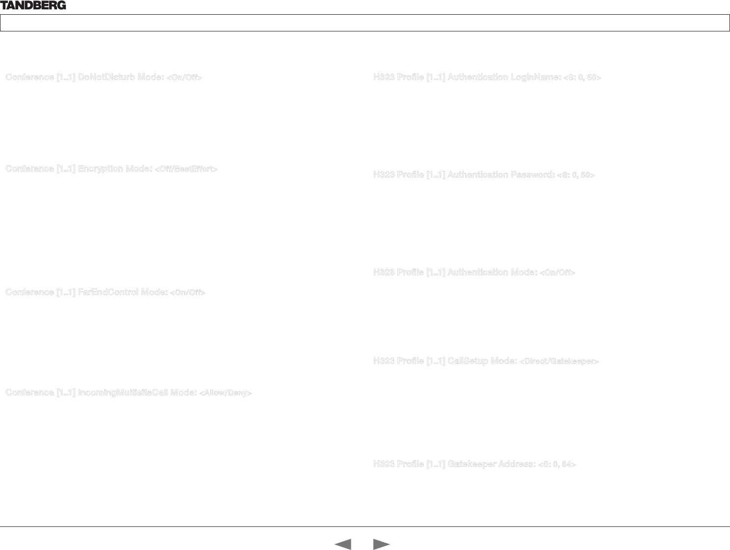
D14324.04—DECEMBER 2009 32
Profile series with Codec C60 Administrator Guide
Contents Introduction Getting started About the menus The settings menu Settings Library Cameras Appendices Contact us
Conference [1..1] DoNotDisturb Mode: <On/Off>
The Do Not Disturb setting determines whether or not there should be an alert on incoming calls.
On: Set to On when you want no alert to incoming calls. The calling side will receive a busy signal when
trying to call the codec.
Off: This is the default setting. The DoNotDisturb is automatically turned Off if the codec receives any IR
signal from the handheld remote control.
Example: DoNotDisturb Mode: Off
Conference [1..1] Encryption Mode: <Off/BestEffort>
BestEffort: The system will use encryption whenever possible.
In Point to point calls: If the far end system supports encryption (AES-128), the call will be encrypted. If not,
the call will proceed without encryption.
In MultiSite calls: In order to have encrypted MultiSite conferences, all sites must support encryption. If not,
the conference will be unencrypted.
Icons on screen: A padlock with the text “Encryption On” displays on screen, for a few seconds, when the
conference starts.
Off: The system will not use encryption.
Example: Conference 1 Encryption Mode: BestEffort
Conference [1..1] FarEndControl Mode: <On/Off>
Lets you decide if the remote side (far end) should be allowed to select your video sources and control your
local camera (pan, tilt, zoom).
On: Set to On when you want the the far end to be able to select your video sources and control your
local camera (pan, tilt, zoom). You will still be able to control your camera and select your video sources as
normal.
Off: When set to Off the far end can not access any of the features above on your system.
Example: Conference 1 FarEndControl Mode: On
Conference [1..1] IncomingMultisiteCall Mode: <Allow/Deny>
The Incoming Multisite Call setting determines whether or not the system should accept incoming calls to an
already active conference.
Allow: When set to Allow, and with an ongoing MCU call/conference, the user can accept another incoming
call. This will result in the incoming call being added to the MCU conference.
Deny: The system will not accept incoming calls when you are in a call. The calling side will receive a busy
signal.
Example: Conference 1 IncomingMultisiteCall Mode: Allow
H323 Profile [1..1] Authentication LoginName: <S: 0, 50>
The system sends the Authentication Login Name and the Authentication Password to a H.323 Gatekeeper
for authentication. The authentication is a one way authentication from the codec to the H.323 Gatekeeper,
i.e. the system is authenticated to the gatekeeper. If the H.323 Gatekeeper indicates that no authentication
is required, the system will still try to register. Requires the H.323 Gatekeeper Authentication Mode to be
enabled.
Format: String with a maximum of 50 characters.
Example: H323 Profile 1 Authentication LoginName: “”
H323 Profile [1..1] Authentication Password: <S: 0, 50>
The system sends the Authentication Login Name and the Authentication Password to a H.323 Gatekeeper
for authentication. The authentication is a one way authentication from the codec to the H.323 Gatekeeper,
i.e. the system is authenticated to the gatekeeper. If the H.323 Gatekeeper indicates that no authentication
is required, the system will still try to register. Requires the H.323 Gatekeeper Authentication Mode to be
enabled.
Format: String with a maximum of 50 characters.
Example: H323 Profile 1 Authentication Password:
H323 Profile [1..1] Authentication Mode: <On/Off>
On: If the H.323 Gatekeeper Authentication Mode is set to On and a H.323 Gatekeeper indicates
that it requires authentication, the system will try to authenticate itself to the gatekeeper. Requires the
Authentication ID and Authentication Password to be defined on both the codec and the Gatekeeper.
Off: If the H.323 Gatekeeper Authentication Mode is set to Off the system will not try to authenticate itself to
a H.323 Gatekeeper, but will still try a normal registration.
Example: H323 Profile 1 Authentication Mode: Off
H323 Profile [1..1] CallSetup Mode: <Direct/Gatekeeper>
The H.323 Call Setup Mode defines whether to use a Gatekeeper or Direct calling when establishing H323
calls.
Direct: An IP-address must be used when dialling in order to make the H323 call.
Gatekeeper: The system will use a Gatekeeper to make a H.323 call. When selecting this option the H323
Profile Gatekeeper Address and H323 Profile Gatekeeper Discovery settings must also be configured.
NOTE! Direct H.323 calls can be made even though the H.323 Call Setup Mode is set to Gatekeeper.
Example: H323 Profile 1 CallSetup Mode: Gatekeeper
H323 Profile [1..1] Gatekeeper Address: <S: 0, 64>
Specifies the IP address of the Gatekeeper. Requires the H.323 Call Setup Mode to be set to Gatekeeper
and the Gatekeeper Discovery to be set to Manual.
Format: String with a maximum of 64 characters.
Example: H323 Profile 1 Gatekeeper Address: “10.47.1.58”
The H323 Profile settingsThe Conference settings, continued...
Contents
Introduction
Getting started
About the menus
The Settings menu
The Settings library
Cameras
Appendices
Contact us
The Settings library
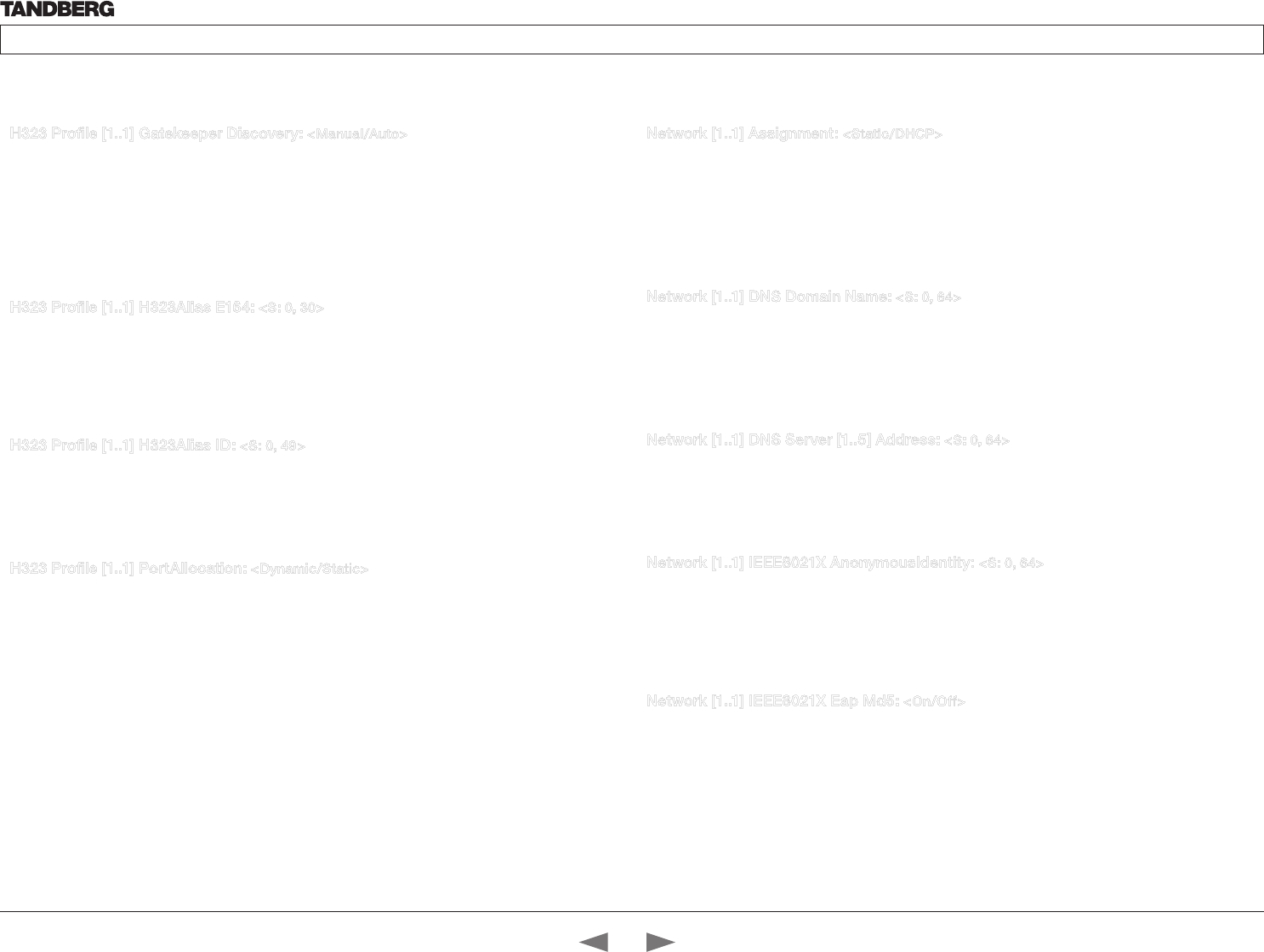
D14324.04—DECEMBER 2009 33
Profile series with Codec C60 Administrator Guide
Contents Introduction Getting started About the menus The settings menu Settings Library Cameras Appendices Contact us
H323 Profile [1..1] Gatekeeper Discovery: <Manual/Auto>
Determines how the system shall register to a H.323 Gatekeeper.
Manual: The system will use a specific Gatekeeper identified by the Gatekeeper’s IP-address.
Auto: The system will automatically try to register to any available Gatekeeper. If a Gatekeeper responds
to the request sent from the codec within 30 seconds this specific Gatekeeper will be used. This requires
that the Gatekeeper is in auto discovery mode as well. If no Gatekeeper responds, the system will not use a
Gatekeeper for making H.323 calls and hence an IP-address must be specified manually.
Example: H323 Profile 1 Gatekeeper Discovery: Manual
H323 Profile [1..1] H323Alias E164: <S: 0, 30>
The H.323 Alias E.164 defines the address of the system, according to the numbering plan implemented
in the H.323 Gatekeeper. The E.164 alias is equivalent to a telephone number, sometimes combined with
access codes.
Format: Compact string with a maximum of 30 characters. Valid characters are 0–9, * and #.
Example: H323 Profile 1 H323Alias E164: “90550092”
H323 Profile [1..1] H323Alias ID: <S: 0, 49>
Lets you specify the H.323 Alias ID which is used to address the system on a H.323 Gatekeeper and will be
displayed in the call lists. Example: “firstname.surname@company.com”, “My H.323 Alias ID”
Format: String with a maximum of 49 characters
Example: H323 Profile 1 H323Alias ID: “firstname.surname@company.com”
H323 Profile [1..1] PortAllocation: <Dynamic/Static>
The H.323 Port Allocation setting affects the H.245 port numbers used for H.323 call signalling.
Dynamic: The system will allocate which ports to use when opening a TCP connection. The reason for doing
this is to avoid using the same ports for subsequent calls, as some firewalls consider this as a sign of attack.
When Dynamic is selected, the H.323 ports used are from 11000 to 20999. Once 20999 is reached they
restart again at 11000. For RTP and RTCP media data, the system is using UDP ports in the range 2326 to
2487. Each media channel is using two adjacent ports, ie 2330 and 2331 for RTP and RTCP respectively.
The ports are automatically selected by the system within the given range. Firewall administrators should not
try to deduce which ports are used when, as the allocation schema within the mentioned range may change
without any further notice.
Static: When set to Static the ports are given within a static predefined range [5555–6555].
Example: H323 Profile 1 PortAllocation: Dynamic
Network [1..1] Assignment: <Static/DHCP>
Defines whether to use DHCP or Static IP assignment.
Static: The IP Address, Subnet Mask and Default Gateway for the system must be specified in the
respective address fields.
DHCP: The system adresses are automatically assigend by the DHCP server.
Changes to this setting requires a restart of the codec.
Example: Network 1 Assignment: DHCP
Network [1..1] DNS Domain Name: <S: 0, 64>
DNS Domain Name is the default domain name suffix which is added to unqualified names.
Example: If the DNS Domain Name is “company.com” and the name to lookup is “MyVideoSystem”, this will
result in the DNS lookup “MyVideoSystem.company.com”.
Format: String with a maximum of 64 characters.
Example: Network 1 DNS Domain Name: “company.com”
Network [1..1] DNS Server [1..5] Address: <S: 0, 64>
Defines the network addresses for DNS servers. Up to 5 addresses may be specified. If the network
addresses are unknown, please contact your administrator or Internet Service Provider.
Format: String with a maximum of 64 characters.
Example: Network 1 DNS Server 1 Address: “”
Network [1..1] IEEE8021X AnonymousIdentity: <S: 0, 64>
The 802.1X Anonymous ID string is to be used as unencrypted identity with EAP types that support
different tunneled identity, like EAP-PEAP and EAP-TTLS. If set, the anonymous ID will be used for the initial
(unencrypted) EAP Identity Request.
Format: String with a maximum of 64 characters.
Example: Network 1 IEEE8021X AnonymousIdentity: “”
Network [1..1] IEEE8021X Eap Md5: <On/Off>
Message-Digest algorith 5. Is a Challenge Handshake Authentication Protocol that relies on a shared secret.
MD5 is a Weak security. EAP - Extensible Authentication Protocol. MD5 - Message Digest Algorithm 5.
On: The EAP-MD5 protocol is enabled. Default mode is On.
Off: The EAP-MD5 protocol is disabled.
Example: Network 1 IEEE8021X Eap Md5: On
The Network settingsThe H323 Profile settings, continued...
Contents
Introduction
Getting started
About the menus
The Settings menu
The Settings library
Cameras
Appendices
Contact us
The Settings library
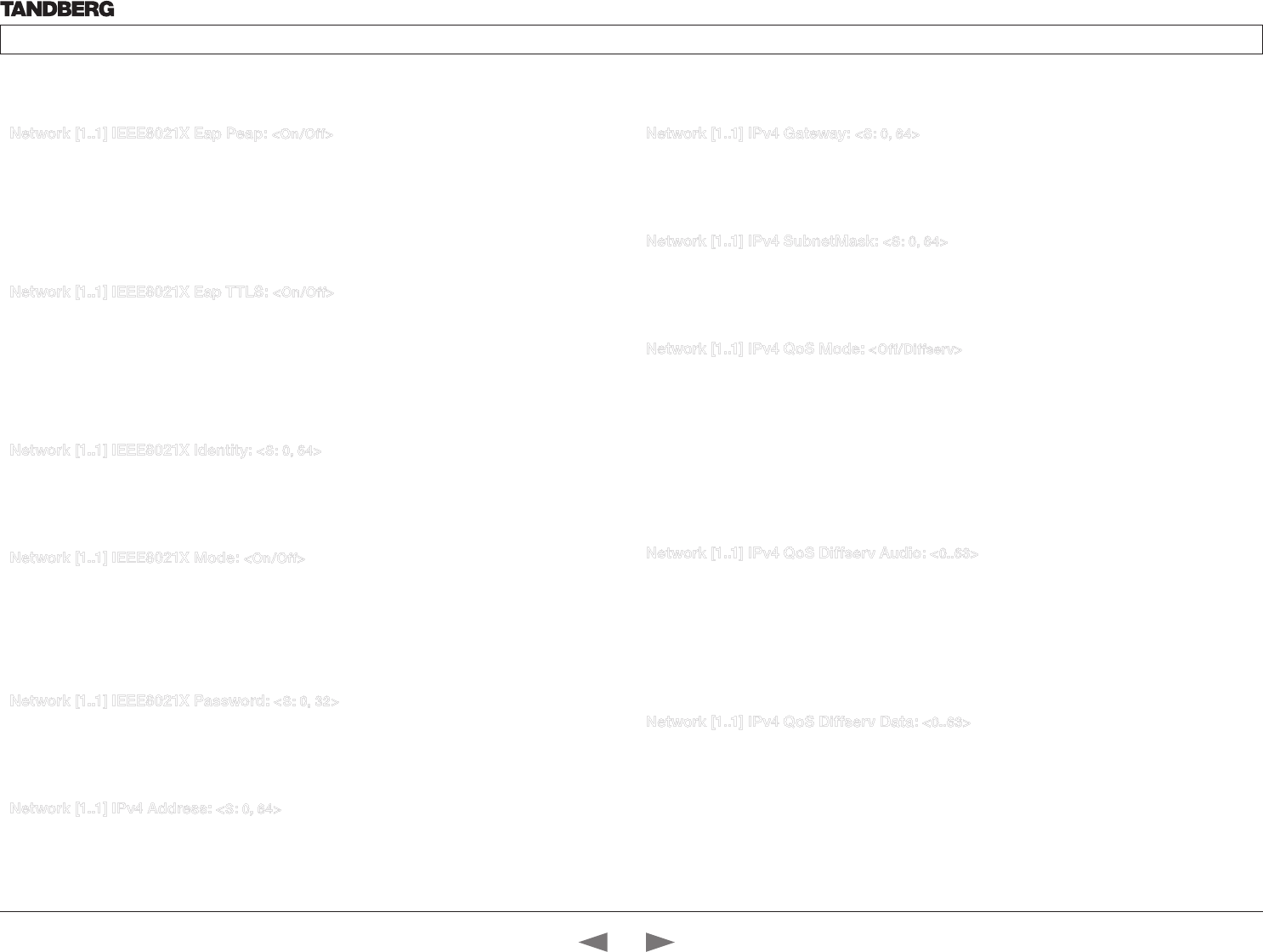
D14324.04—DECEMBER 2009 34
Profile series with Codec C60 Administrator Guide
Contents Introduction Getting started About the menus The settings menu Settings Library Cameras Appendices Contact us
Network [1..1] IEEE8021X Eap Peap: <On/Off>
Protected Transport Layer Security. Developed by Microsoft, Cisco and RSA Security. Authenticates LAN
clients without the need for client certificates. EAP - Extensible Authentication Protocol. PEAP - Protected
Extensible Authentication Protocol.
On: The EAP-PEAP protocol is enabled. Default mode is On.
Off: The EAP-PEAP protocol is disabled.
Example: Network 1 IEEE8021X Eap Peap: On
Network [1..1] IEEE8021X Eap TTLS: <On/Off>
Tunneled Transport Layer Security. Developed by Funk Software and Certicom. Usually supported by
Agere Systems, Proxim and Avaya. Authenticates LAN clients without the need for client certificates. EAP -
Extensible Authentication Protocol. TTLS - Tunneled Transport Layer Security.
On: The EAP-TTLS protocol is enabled. Default mode is On.
Off: The EAP-TTLS protocol is disabled.
Example: Network 1 IEEE8021X Eap TTLS: On
Network [1..1] IEEE8021X Identity: <S: 0, 64>
The 802.1X Identity is the user name needed for 802.1X authentication.
Format: String with a maximum of 64 characters.
Example: Network 1 IEEE8021X Identity: “”
Network [1..1] IEEE8021X Mode: <On/Off>
The system may be connected to an IEEE 802.1X LAN network with a port-based network access control
that is used to provide authenticated network access for Ethernet networks.
On: The 802.1X authentication is enabled.
Off: The 802.1X authentication is disabled. Default mode is Off.
Example: Network 1 IEEE8021X Mode: Off
Network [1..1] IEEE8021X Password: <S: 0, 32>
The 802.1X Password is the password needed for 802.1X authentication.
Format: String with a maximum of 32 characters.
Example: Network 1 IEEE8021X Password: “***”
Network [1..1] IPv4 Address: <S: 0, 64>
Defines the Static IP address for the system. Only applicable if Static IP assignment is chosen.
Format: Compact string with a maximum of 64 characters.
Example: Network 1 IPv4 Address: “10.47.5.100”
Network [1..1] IPv4 Gateway: <S: 0, 64>
Defines the IP default gateway. Only applicable if Static IP assignment is chosen.
Format: Compact string with a maximum of 64 characters.
Example: Network 1 IPv4 Gateway: “10.47.5.100”
Network [1..1] IPv4 SubnetMask: <S: 0, 64>
Defines the IP subnet mask. Only applicable if Static IP assignment is chosen.
Format: Compact string with a maximum of 64 characters.
Example: Network 1 IPv4 SubnetMask: “255.255.255.0”
Network [1..1] IPv4 QoS Mode: <Off/Diffserv>
Defines whether IP Diffserv QoS should be used. The QoS (Quality of Service) is a method which
handles the priority of audio, video and data in the network. The QoS settings must be supported by the
infrastructure. DiffServ (Differentiated Services) is a computer networking architecture that specifies a
simple, scalable and coarse-grained mechanism for classifying, managing network traffic and providing
QoS priorities on modern IP networks.
Off: When set to Off no QoS method is used.
Diffserv: Select Diffserv and then go to the Diffserv sub-menus (Audio, Data, Signalling and Video) to
configure these settings.
Example: Network 1 IPv4 QoS Mode: diffserv
Network [1..1] IPv4 QoS Diffserv Audio: <0..63>
The DiffServ Audio setting is used to define which priority Audio packets should have in an IP network.
Enter a priority, which ranges from 0 to 63 for the packets. The higher the number, the higher the priority.
These priorities might be overridden when packets are leaving the network controlled by the local network
administrator.
Audio: A recommended value is DiffServ Code Point (DSCP) is AF41, which equals the value 34. If in doubt,
contact your network administrator. Range: 0-63
Example: Network 1 IPv4 QoS Diffserv Audio: 0
Network [1..1] IPv4 QoS Diffserv Data: <0..63>
The DiffServ Data setting is used to define which priority Data packets should have in an IP network.
Enter a priority, which ranges from 0 to 63 for the packets. The higher the number, the higher the priority.
These priorities might be overridden when packets are leaving the network controlled by the local network
administrator.
Data: A recommended value is DiffServ Code Point (DSCP) AF23, which equals the value 22. If in doubt,
contact your network administrator. Range: 0-63
Example: Network 1 IPv4 QoS Diffserv Data: 0
The Network settings, continued... The Network settings, continued...
Contents
Introduction
Getting started
About the menus
The Settings menu
The Settings library
Cameras
Appendices
Contact us
The Settings library
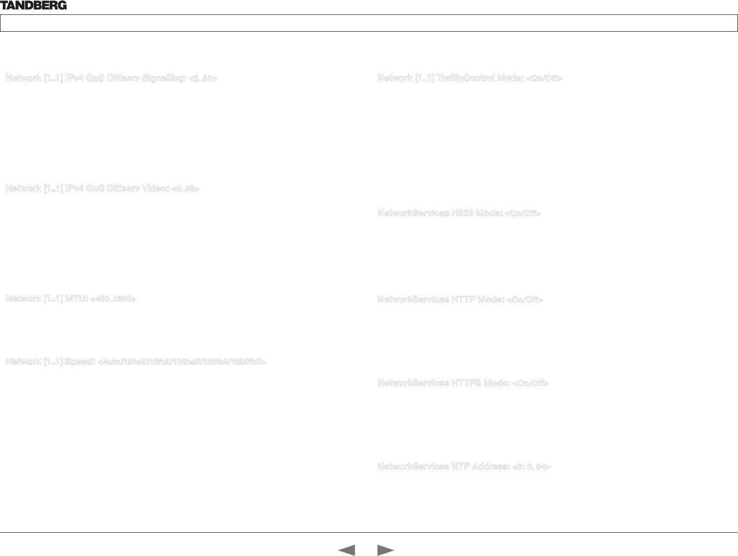
D14324.04—DECEMBER 2009 35
Profile series with Codec C60 Administrator Guide
Contents Introduction Getting started About the menus The settings menu Settings Library Cameras Appendices Contact us
Network [1..1] IPv4 QoS Diffserv Signalling: <0..63>
The DiffServ Signalling setting is used to define which priority Signalling packets should have in an IP
network. Enter a priority, which ranges from 0 to 63 for the packets. The higher the number, the higher the
priority. These priorities might be overridden when packets are leaving the network controlled by the local
network administrator.
Signalling: A recommended value is DiffServ Code Point (DSCP) AF31 which equals the value 26. If in
doubt, contact your network administrator.
Range: 0-63
Example: Network 1 IPv4 QoS Diffserv Signalling: 0
Network [1..1] IPv4 QoS Diffserv Video: <0..63>
The DiffServ Video setting is used to define which priority Video packets should have in an IP network.
Enter a priority, which ranges from 0 to 63 for the packets. The higher the number, the higher the priority.
These priorities might be overridden when packets are leaving the network controlled by the local network
administrator.
Video: A recommended value is DiffServ Code Point (DSCP) AF41, which equals the value 34. If in doubt,
contact your network administrator.
Range: 0-63
Example: Network 1 IPv4 QoS Diffserv Video: 0
Network [1..1] MTU: <400..1500>
Set the ethernet MTU (Maximum Transmission Unit).
Range: 400-1500
Example: Network 1 MTU: 1500
Network [1..1] Speed: <Auto/10half/10full/100half/100full/1000full>
Set the ethernet link speed.
Auto: Autonegotiate link speed.
10half: Force link to 10Mbps half-duplex.
10full: Force link to 10Mbps full-duplex.
100half: Force link to 100Mbps half-duplex.
100full: Force link to 100Mbps full-duplex.
1000full: Force link to 1Gbps full-duplex.
Example: Network 1 Speed: Auto
Network [1..1] TrafficControl Mode: <On/Off>
Configure how video packets transmission speed shall be controlled.
On: Transmit video packets at maximum 20Mbps. Can be used to smooth out bursts in the outgoing
network traffic.
Off: Transmit video packets at link speed.
Example: Network 1 TrafficControl: On
The Network Services settings
The Network settings, continued... The Network settings, continued...
NetworkServices H323 Mode: <On/Off>
Determines whether the system should be able to place and receive H.323 calls.
On: Set to On to enable the possibility to place and receive H.323 calls.This is the default setting.
Off: Set to Off to disable the possibility to place and receive H.323 calls.
NOTE! Changes in this setting requires the codec to be restarted.
Example: NetworkServices H323 Mode: On
NetworkServices HTTP Mode: <On/Off>
HTTP is a web-interface for system management, call management such as call transfer, diagnostics and
software uploads.
On: The HTTP protocol is enabled.
Off: The HTTP protocol is disabled.
Example: NetworkServices HTTP Mode: On
NetworkServices HTTPS Mode: <On/Off>
HTTPS is a Web protocol that encrypts and decrypts user page requests as well as the pages that are
returned by the Web server.
On: The HTTPS protocol is enabled.
Off: The HTTPS protocol is disabled.
Example: NetworkServices HTTPS Mode: On
NetworkServices NTP Address: <S: 0, 64>
Enter the NTP Address to define the network time protocol server address. This address will be used if NTP
Mode is set to Manual, or if set to Auto and no address is supplied by a DHCP server.
Format: String with a maximum of 64 characters.
Example: NetworkServices NTP Address: “1.tandberg.pool.ntp.org”
Contents
Introduction
Getting started
About the menus
The Settings menu
The Settings library
Cameras
Appendices
Contact us
The Settings library
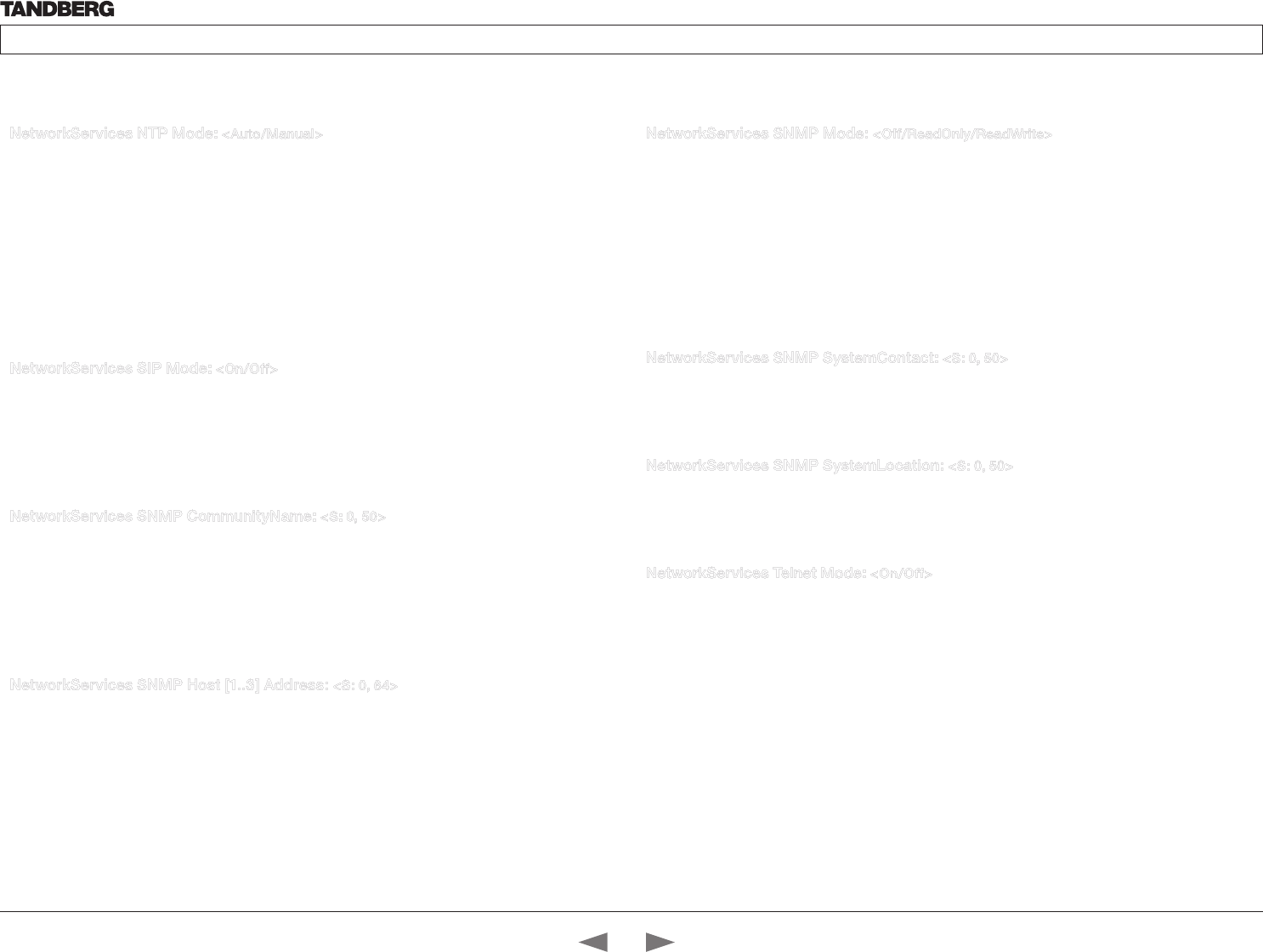
D14324.04—DECEMBER 2009 36
Profile series with Codec C60 Administrator Guide
Contents Introduction Getting started About the menus The settings menu Settings Library Cameras Appendices Contact us
NetworkServices NTP Mode: <Auto/Manual>
The Network Time Protocol (NTP) is used to synchronize the time of the system to a reference time server.
The time server will subsequently be queried every 24th hour for time updates. The time will be displayed
on the top of the screen. The system will use the time to timestamp messages transmitted to Gatekeepers
or Border Controllers requiring H.235 authentication. The system will use the time to timestamp messages
transmitted to Gatekeepers or Border Controllers that requires H.235 authentication. It is also used for
timestamping Placed Calls, Missed Calls and Received Calls.
Auto: The system will use the NTP server, by which address is supplied from the DHCP server in the
network. If no DHCP server is used, or the DHCP server does not provide the system with a NTP server
address, the system will use the static defined NTP server address specified by the user.
Manual: The system will always use the static defined NTP server address specified by the user.
Example: NetworkServices NTP Mode: Manual
NetworkServices SIP Mode: <On/Off>
Determines whether the system should be able to place and receive SIP calls.
On: Set to On to enable the possibility to place and receive SIP calls.This is the default setting.
Off: Set to Off to disable the possibility to place and receive SIP calls.
NOTE! Changes in this setting requires the codec to be restarted.
Example: NetworkServices SIP Mode: On
NetworkServices SNMP CommunityName: <S: 0, 50>
Enter the name of the Network Services SNMP Community. SNMP Community names are used to
authenticate SNMP requests. SNMP requests must have a ‘password’ (case sensitive) in order to receive a
response from the SNMP Agent in the codec. The default password is “public”. If you have the TANDBERG
Management Suite (TMS) you must make sure the same SNMP Community is configured there too. Note!
The SNMP Community password is case sensitive.
Format: String with a maximum of 50 characters.
Example: NetworkServices SNMP CommunityName: “public”
NetworkServices SNMP Host [1..3] Address: <S: 0, 64>
Enter the address of up to three SNMP Managers. All traps will then be sent to the hosts listed.
The system’s SNMP Agent (in the codec) responds to requests from SNMP Managers (a PC program etc.).
SNMP Traps are generated by the SNMP Agent to inform the SNMP Manager about important events. Can
be used to send event created messages to the SNMP agent about different events like: system reboot,
system dialing, system disconnecting, MCU call, packet loss etc. Traps can be sent to multiple SNMP Trap
Hosts.
Format: String with a maximum of 64 characters.
Example: NetworkServices SNMP Host 1 Address: “”
NetworkServices SNMP Mode: <Off/ReadOnly/ReadWrite>
SNMP (Simple Network Management Protocol) is used in network management systems to monitor
network-attached devices (routers, servers, switches, projectors, etc) for conditions that warrant
administrative attention. SNMP exposes management data in the form of variables on the managed
systems, which describe the system configuration. These variables can then be queried (set to ReadOnly)
and sometimes set (set to ReadWrite) by managing applications.
Off: Set to Off when you want to disable the SNMP network service.
ReadOnly: Set to ReadOnly when you want to enable the SNMP network service for queries only.
ReadWrite: Set to ReadOnly when you want to enable the SNMP network service for both queries and
commands.
Example: NetworkServices SNMP Mode: ReadWrite
NetworkServices SNMP SystemContact: <S: 0, 50>
Enter the name of the Network Services SNMP System Contact.
Format: String with a maximum of 50 characters.
Example: NetworkServices SNMP SystemContact: “”
NetworkServices SNMP SystemLocation: <S: 0, 50>
Enter the name of the Network Services SNMP System Location.
Format: String with a maximum of 50 characters.
Example: NetworkServices SNMP SystemLocation: “”
NetworkServices Telnet Mode: <On/Off>
Telnet is a network protocol used on the Internet or local area network (LAN) connections.
On: The Telnet protocol is enabled.
Off: The Telnet protocol is disabled. This is the default factory setting.
Example: NetworkServices Telnet Mode: Off
The Network Services settings, continued... The Network Services settings, continued...
Contents
Introduction
Getting started
About the menus
The Settings menu
The Settings library
Cameras
Appendices
Contact us
The Settings library
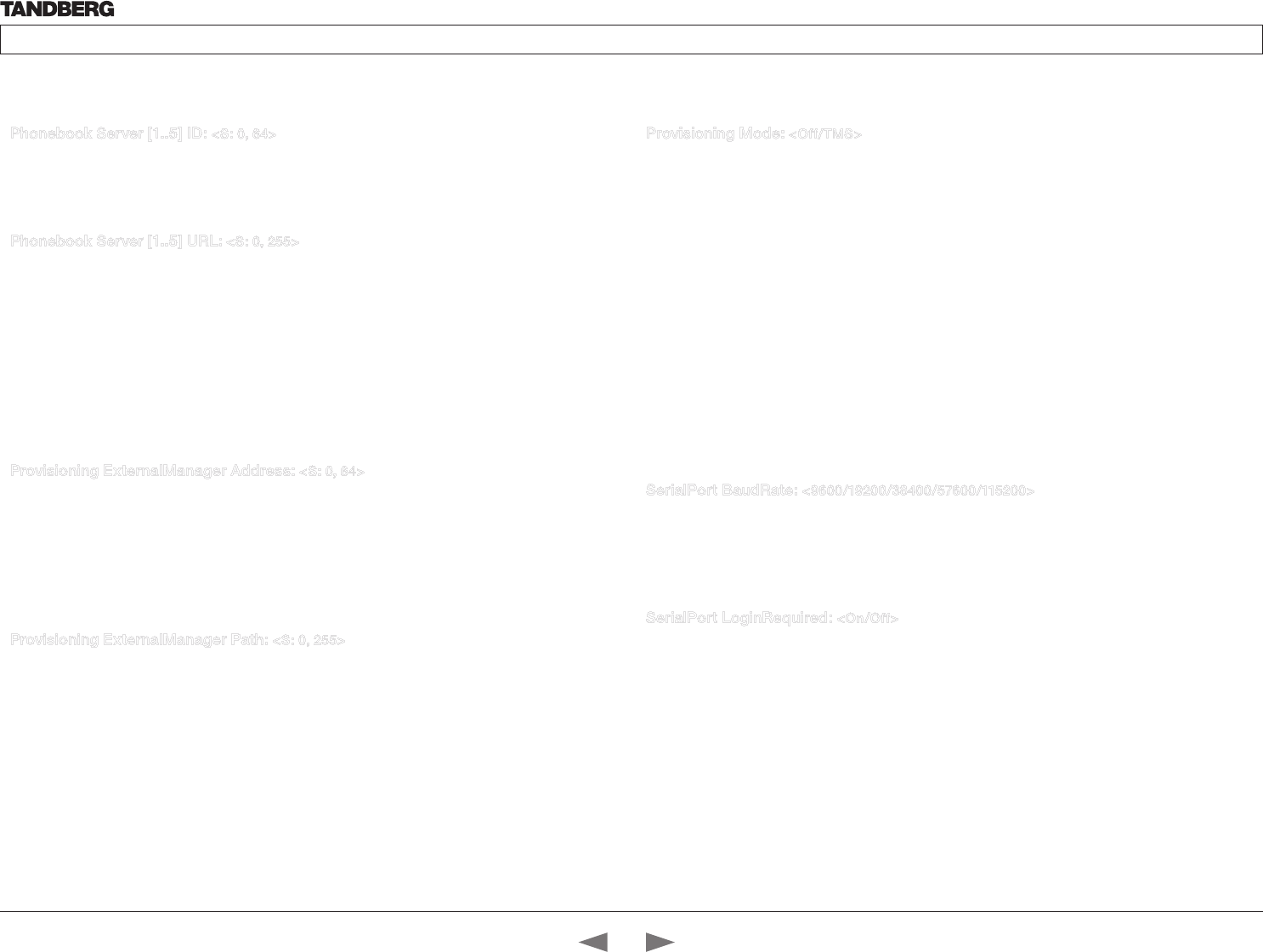
D14324.04—DECEMBER 2009 37
Profile series with Codec C60 Administrator Guide
Contents Introduction Getting started About the menus The settings menu Settings Library Cameras Appendices Contact us
Phonebook Server [1..5] ID: <S: 0, 64>
Enter a name for the external phonebook. Addresses the specific phonebook.
Format: String with a maximum of 64 characters.
Example: Phonebook Server 1 ID: “”
Phonebook Server [1..5] URL: <S: 0, 255>
Enter the address (URL) to the external phonebook server. Addresses the specific phonebook server.
Format: String with a maximum of 255 characters.
Example: Phonebook Server 1 URL: “http://tms.company.com/tms/public/external/
phonebook/phonebook.asmx”
Provisioning Mode: <Off/TMS>
Provides the possibility of managing the codec (endpoint) by using an external manager/management
system.
Off: The system will not try to register to any management system.
TMS: If set to TMS the system will try to register with a TMS server as described in Provisioning
ExternalManager settings. TMS is short for TANDBERG Management System. Please contact your
TANDBERG representative for more information.
Example: Provisioning Mode: TMS
SerialPort BaudRate: <9600/19200/38400/57600/115200>
Specify the baud rate (bps) on the COM port (data port). The default value is 38400.
Other default parameters for the COM port are: Parity: None Databits: 8 Stopbits: 1 Flow control: None.
Valid inputs for baud rate: 9600, 19200, 38400, 57600, 115200 bits/second.
Example: SerialPort BaudRate: 38400
SerialPort LoginRequired: <On/Off>
The Serial Login setting determines whether or not there should be a login when connecting to the COM
port (data port).
On: Login is required when connecting to the COM port (data port).
Off: The user can access the COM port (data port) without any login.
Example: SerialPort LoginRequired: On
The Provisioning settings The Serial Port settings
The Phonebook settings
Provisioning ExternalManager Address: <S: 0, 64>
Specifies the IP Address to the External Manager/Management system. If an External Manager address
and a path is configured, the system will post an HTTP message to this address when starting up.
When receiving this HTTP posting the External Manager (typically a management system) can return
configurations/commands to the unit as a result. If the DHCP Option 242 is returned in the DHCP response
from the DHCP server the system will interpret this as the External Manager address to use.
Format: String with a maximum of 64 characters.
Example: Provisioning ExternalManager Address: “”
Provisioning ExternalManager Path: <S: 0, 255>
Specifies the path to the External Manager/Management system. If an External Manager address and a path
is configured, the system will post an HTTP message to this address when starting up. When receiving this
HTTP posting the External Manager (typically a management system) can return configurations/commands
to the unit as a result. If the DHCP Option 242 is returned in the DHCP response from the DHCP server the
system will interpret this as the External Manager address to use.
Format: String with a maximum of 255 characters.
Example: Provisioning ExternalManager Path: “tms/public/external/management/
SystemManagementService.asm x”
The Provisioning settings, continued...
Contents
Introduction
Getting started
About the menus
The Settings menu
The Settings library
Cameras
Appendices
Contact us
The Settings library
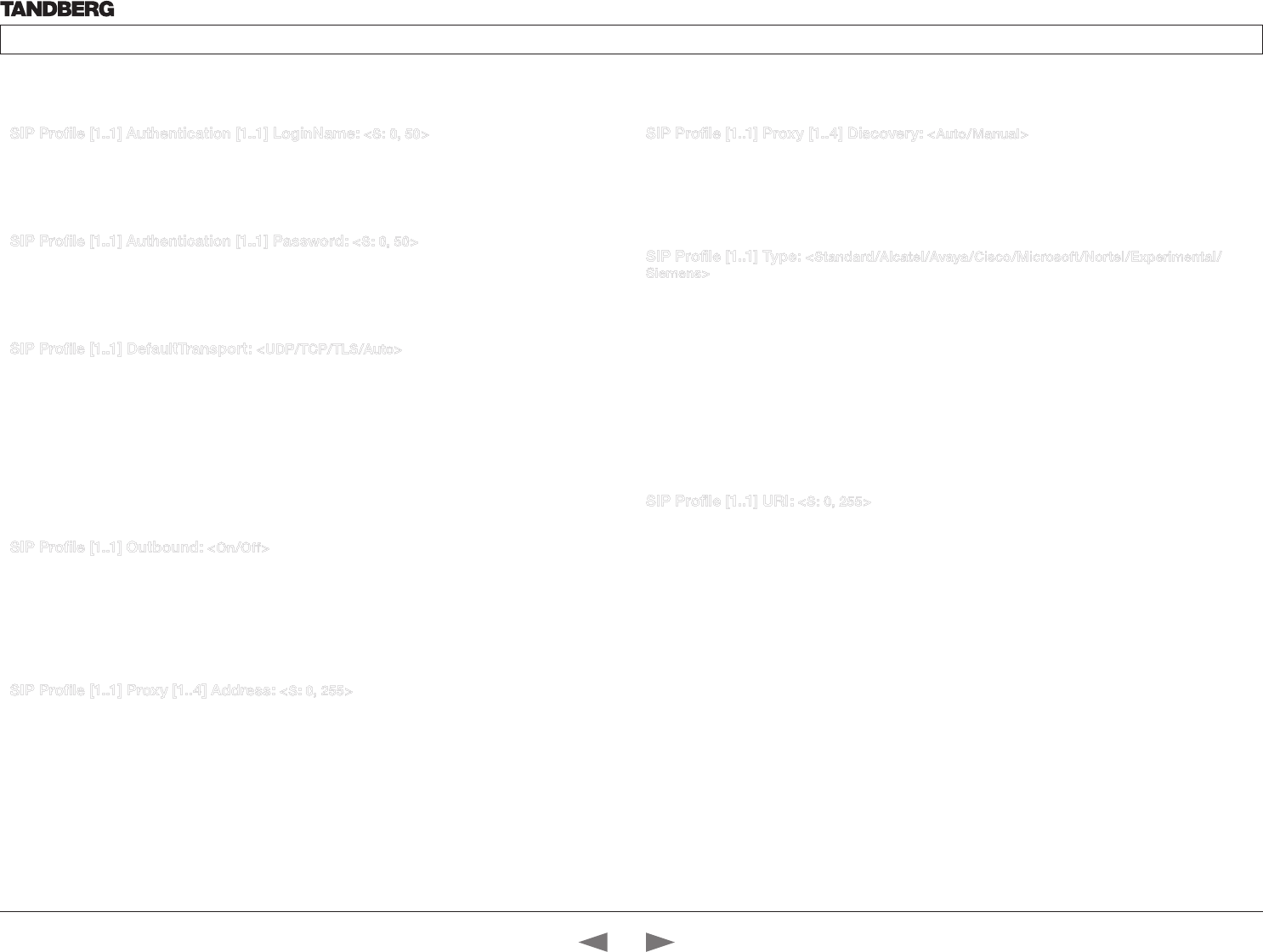
D14324.04—DECEMBER 2009 38
Profile series with Codec C60 Administrator Guide
Contents Introduction Getting started About the menus The settings menu Settings Library Cameras Appendices Contact us
SIP Profile [1..1] Proxy [1..4] Discovery: <Auto/Manual>
Manual: When Manual is selected, the manually configured SIP Proxy address will be used
Auto: When Auto is selected, the SIP Proxy address is obtained using Dynamic Host Configuration Protocol
(DHCP).
Example: SIP Profile 1 Proxy 1 Discovery: Manual
SIP Profile [1..1] Type: <Standard/Alcatel/Avaya/Cisco/Microsoft/Nortel/Experimental/
Siemens>
Enables SIP extensions and special behaviour for a vendor or provider
Standard: Should be used when registering to standard SIP proxy like OpenSer.
Alcatel: Must be used when registering to a Alcatel-Lucent OmniPCX Enterprise R7 or later.
Avaya: Must be used when registered to a Avaya Communication Manager.
Cisco: Must be used when registering to a Cisco CallManager version 5 or later.
Microsoft: Must be used when registering to a Microsoft LCS or OCS server.
Nortel: Must be used when registering to a Nortel MCS 5100 or MCS 5200 PBX.
Experimental: Can be used if auto is not working Note! This mode is for testing purposes only.
Example: SIP Profile 1 Type: Standard
SIP Profile [1..1] URI: <S: 0, 255>
The SIP URI or number is used to address the system. This is the URI that is registered and used by the
SIP services to route inbound calls to the system. A Uniform Resource Identifier (URI) is a compact string of
characters used to identify or name a resource.
Format: Compact string with a maximum of 255 characters.
Example: SIP Profile 1 URI: “sip:name@example.com”
SIP Profile [1..1] Authentication [1..1] LoginName: <S: 0, 50>
This is the user name part of the credentials used to authenticate towards the SIP proxy.
Format: String with a maximum of 50 characters.
Example: SIP Profile 1 Authentication 1 LoginName: “”
SIP Profile [1..1] Authentication [1..1] Password: <S: 0, 50>
This is the password part of the credentials used to authenticate towards the SIP proxy.
Format: String with a maximum of 50 characters.
Example: SIP Profile 1 Authentication 1 Password:
SIP Profile [1..1] DefaultTransport: <UDP/TCP/TLS/Auto>
Select the transport protocol to be used over the LAN.
UDP: The system will always use UDP as the default transport method.
TCP: The system will always use TCP as the default transport method.
TLS: The system will always use TLS as the default transport method. For TLS connections a SIP CA-list
can be uploaded using the web interface. If no such CA-list is available on the system then anonymous Diffie
Hellman will be used.
Auto: The system will try to connect using transport protocols in the following order: TLS, TCP, UDP.
Example: SIP Profile 1 DefaultTransport: Auto
SIP Profile [1..1] Outbound: <On/Off>
The client initiated connections mechanism for firewall traversal, connection reuse and redundancy. The
current version supports http://tools.ietf.org/html/draft-ietf-sip-outbound-20.
On: Set up multiple outbound connections to servers in the Proxy Address list.
Off: Connect to the single proxy configured first in Proxy Address list.
Example: SIP Profile 1 Outbound: Off
SIP Profile [1..1] Proxy [1..4] Address: <S: 0, 255>
The Proxy Address is the manually configured address for the outbound proxy. It is possible to use a fully
qualified domain name, or an IP address. The default port is 5060 for TCP and UDP but another one can be
provided. If Outbound is enabled, multiple proxies can be addressed.
Format: Compact string with a maximum of 255 characters.
Example: SIP Profile 1 Proxy 1 Address: “”
The SIP Profile settings The SIP Profile settings, continued...
Contents
Introduction
Getting started
About the menus
The Settings menu
The Settings library
Cameras
Appendices
Contact us
The Settings library
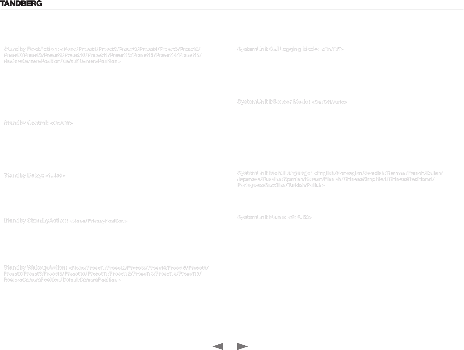
D14324.04—DECEMBER 2009 39
Profile series with Codec C60 Administrator Guide
Contents Introduction Getting started About the menus The settings menu Settings Library Cameras Appendices Contact us
Standby BootAction: <None/Preset1/Preset2/Preset3/Preset4/Preset5/Preset6/
Preset7/Preset8/Preset9/Preset10/Preset11/Preset12/Preset13/Preset14/Preset15/
RestoreCameraPosition/DefaultCameraPosition>
Decide what the system is going to do on boot.
None: No action.
Preset 1..15: Activate the selected preset.
RestoreCameraPosition: Set the camera to the position it had before the last boot.
DefaultCameraPosition: Set the camera to the factory default position.
Example: Standby BootAction: DefaultCameraPosition
Standby Control: <On/Off>
Determine whether the system should go into standby mode or not.
On: Enter standby mode when the Standby Delay has timed out. Requires the Standby Delay to be set to an
appropriate value.
Off: Not entering standby mode.
Example: Standby Control: On
Standby Delay: <1..480>
Define how long (in minutes) the system shall be in idle mode before it goes into standby mode. Requires
the Standby Control to be enabled.
Range: 1-480 minutes
Example: Standby Delay: 10
Standby StandbyAction: <None/PrivacyPosition>
The setting determines what the system is going to do when going into standby mode.
None: No action.
PrivacyPosition: Turns the camera to a sideways position for privacy.
Example: Standby StandbyAction: PrivacyPosition
Standby WakeupAction: <None/Preset1/Preset2/Preset3/Preset4/Preset5/Preset6/
Preset7/Preset8/Preset9/Preset10/Preset11/Preset12/Preset13/Preset14/Preset15/
RestoreCameraPosition/DefaultCameraPosition>
Decide what the system is going to do when leaving standby mode.
None: No action.
Preset 1..15: Activate the selected preset.
RestoreCameraPosition: Set the camera to the position it had before entering standby.
DefaultCameraPosition: Set the camera to the factory default position.
Example: Standby WakeupAction: RestoreCameraPosition
SystemUnit CallLogging Mode: <On/Off>
Enables/disables logging of calls received or placed by the system. The call logs may then be viewed via the
GUI or using the xHistory command.
On: Enable logging.
Off: Disable logging.
Example: SystemUnit CallLogging Mode: On
SystemUnit IrSensor Mode: <On/Off/Auto>
The System Unit IR Sensor setting determines whether the infrared receiver on the codec should be enabled
or not. The IR sensor LED is located in the front of the codec and flickers when an ir signal is received from
the remote control.
On: Set to On to enable the IR sensor on the codec.
Off: Set to Off to disable the IR sensor on the codec.
Auto: The system will automatically disable the IR sensor on the codec if the IR sensor at camera is enabled.
Otherwise the IR sensor on the codec will be enabled.
Example: SystemUnit IrSensor Mode: On
SystemUnit MenuLanguage: <English/Norwegian/Swedish/German/French/Italian/
Japanese/Russian/Spanish/Korean/Finnish/ChineseSimplified/ChineseTraditional/
PortugueseBrazilian/Turkish/Polish>
Select a language for the menus on screen.
Example: SystemUnit MenuLanguage: English
SystemUnit Name: <S: 0, 50>
Enter a System Name to define a name of the system unit. If the H.323 Alias ID is configured on the system
then this ID will be used instead of the system name. The system name will be displayed:
* When the codec is acting as an SNMP Agent
* Towards a DHCP server
Format: String with a maximum of 50 characters.
Example: SystemUnit Name: “Meeting Room Name”
The System Unit settingsThe Standby settings
Contents
Introduction
Getting started
About the menus
The Settings menu
The Settings library
Cameras
Appendices
Contact us
The Settings library
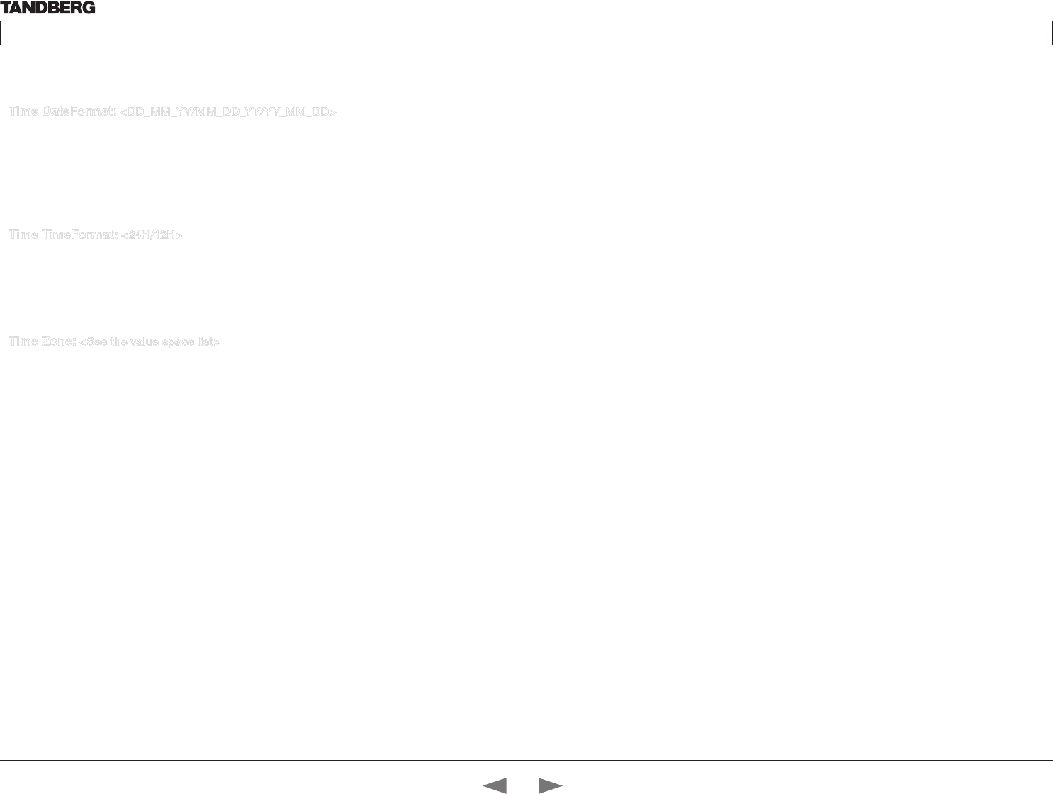
D14324.04—DECEMBER 2009 40
Profile series with Codec C60 Administrator Guide
Contents Introduction Getting started About the menus The settings menu Settings Library Cameras Appendices Contact us
Time DateFormat: <DD_MM_YY/MM_DD_YY/YY_MM_DD>
Specifies the date format.
DD_MM_YY: The date January 30th 2009 will be displayed: 30.01.09
MM_DD_YY: The date January 30th 2009 will be displayed: 01.30.09
YY_MM_DD: The date January 30th 2009 will be displayed: 09.01.30
Example: Time DateFormat: DD_MM_YY
Time TimeFormat: <24H/12H>
Specifies the time format.
24H: Set the time format to 24 hours.
12H: Set the time format to 12 hours (AM/PM).
Example: Time TimeFormat: 24H
Time Zone: <See the value space list>
Specifies the time zone where the system is located, using Windows time zone description format.
Value space list:
GMT-12:00 (International Date Line West)
GMT-11:00 (Midway Island, Samoa)
GMT-10:00 (Hawaii)
GMT-09:00 (Alaska)
GMT-08:00 (Pacific Time (US & Canada) Tijuana)
GMT-07:00 (Arizona)
GMT-07:00 (Mountain Time (US & Canada))
GMT-07:00 (Chihuahua, La Paz, Mazatlan)
GMT-06:00 (Central America)
GMT-06:00 (Saskatchewan)
GMT-06:00 (Guadalajara, Mexico City, Monterrey)
GMT-06:00 (Central Time (US & Canada))
GMT-05:00 (Indiana (East))
GMT-05:00 (Bogota, Lima, Quito)
GMT-05:00 (Eastern Time (US & Canada))
GMT-04:30 (Caracas)
GMT-04:00 (La Paz)
GMT-04:00 (Santiago)
GMT-04:00 (Atlantic Time (Canada))
GMT-03:30 (Newfoundland)
GMT-03:00 (Buenos Aires, Georgetown)
GMT-03:00 (Greenland)
GMT-03:00 (Brasilia)
GMT-02:00 (Mid-Atlantic)
GMT-01:00 (Cape Verde Is.)
GMT-01:00 (Azores)
GMT (Casablanca, Monrovia)
GMT (Greenwich Mean Time : Dublin, Edinburgh, Lisbon, London)
GMT+01:00 (West Central Africa)
GMT+01:00 (Amsterdam, Berlin, Bern, Rome, Stockholm, Vienna)
GMT+01:00 (Brussels, Copenhagen, Madrid, Paris)
GMT+01:00 (Sarajevo, Skopje, Warsaw, Zagreb)
GMT+01:00 (Belgrade, Bratislava, Budapest, Ljubljana, Prague)
GMT+02:00 (Harare, Pretoria)
GMT+02:00 (Jerusalem)
GMT+02:00 (Athens, Istanbul, Minsk)
GMT+02:00 (Helsinki, Kyiv, Riga, Sofia, Tallinn, Vilnius)
GMT+02:00 (Cairo)
GMT+02:00 (Bucharest)
GMT+03:00 (Nairobi)
GMT+03:00 (Kuwait, Riyadh)
GMT+03:00 (Moscow, St. Petersburg, Volgograd)
GMT+03:00 (Baghdad)
GMT+03:30 (Tehran)
GMT+04:00 (Abu Dhabi, Muscat)
GMT+04:00 (Baku, Tbilisi, Yerevan)
GMT+04:30 (Kabul)
GMT+05:00 (Islamabad, Karachi, Tashkent)
GMT+05:00 (Ekaterinburg)
GMT+05:30 (Chennai, Kolkata, Mumbai, New Delhi)
GMT+05:45 (Kathmandu)
GMT+06:00 (Sri Jayawardenepura)
GMT+06:00 (Astana, Dhaka)
GMT+06:00 (Almaty, Novosibirsk)
GMT+06:30 (Rangoon)
GMT+07:00 (Bangkok, Hanoi, Jakarta)
GMT+07:00 (Krasnoyarsk)
GMT+08:00 (Perth)
GMT+08:00 (Taipei)
The Time settings The Time settings, continued...
Contents
Introduction
Getting started
About the menus
The Settings menu
The Settings library
Cameras
Appendices
Contact us
The Settings library
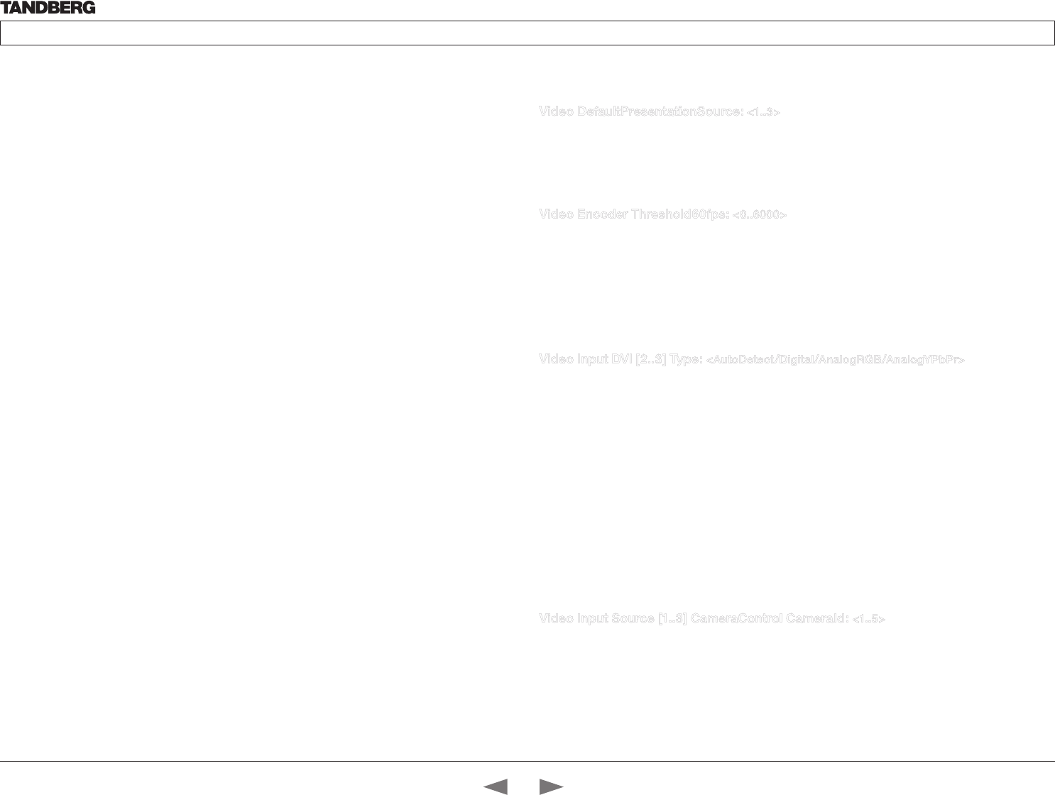
D14324.04—DECEMBER 2009 41
Profile series with Codec C60 Administrator Guide
Contents Introduction Getting started About the menus The settings menu Settings Library Cameras Appendices Contact us
GMT+08:00 (Kuala Lumpur, Singapore)
GMT+08:00 (Beijing, Chongqing, Hong Kong, Urumqi)
GMT+08:00 (Irkutsk, Ulaan Bataar)
GMT+09:00 (Osaka, Sapporo, Tokyo)
GMT+09:00 (Seoul)
GMT+09:00 (Yakutsk)
GMT+09:30 (Darwin)
GMT+09:30 (Adelaide)
GMT+10:00 (Guam, Port Moresby)
GMT+10:00 (Brisbane)
GMT+10:00 (Vladivostok)
GMT+10:00 (Hobart)
GMT+10:00 (Canberra, Melbourne, Sydney)
GMT+11:00 (Magadan, Solomon Is., New Caledonia)
GMT+12:00 (Fiji, Kamchatka, Marshall Is.)
GMT+12:00 (Auckland, Wellington)
GMT+13:00 (Nuku alofa)
Example: Time Zone: “GMT (Greenwich Mean Time : Dublin, Edinburgh, Lisbon,
London)”
Video DefaultPresentationSource: <1..3>
Define which video input source shall be used as the default presentation source (e.g. when you press the
Presentation key on the remote control). The input source is configured to a video input connector.
Range: 1-3 presentation sources
Example: Video DefaultPresentationSource: 3
Video Encoder Threshold60fps: <0..6000>
If the bandwidth used for transmitting video is above or equal to this threshold, the system will select the
highest video resolution possible while maintaining 60 fps. If below this threshold, the system will select the
highest video resolution possible while maintaining 30fps.
NOTE: This setting will only apply when the video input source to be transmitted is a 60fps source, and the
selected video input is configured for motion.
Range: 0-6000 kbps
Example: Video Encoder Threshold60fps: 2048
Video Input DVI [2..3] Type: <AutoDetect/Digital/AnalogRGB/AnalogYPbPr>
The official DVI standard supports both digital and analog signals. In most cases the default AutoDetect
setting can detect whether the signal is analog RGB or digital. However, in some rare cases when DVI-I
cables are used (these cables can carry both the analog and digital signals) this detection might fail. This
setting makes it possible to override the AutoDetect and select the correct DVI video input.
This setting should also be used if the video input is an analog component (YPbPr) type signal. This is
used by some cameras (Sony EVI-HD1) and DVD/Blu-ray players. Since it is not possible to auto detect the
difference between AnalogRGB and AnalogYPbPr, the Analog YPbPr setting has to be selected.
AutoDetect: Set to AutoDetect to automatically detect if the signal is analog RGB or digital.
Digital: Set to Digital to force the DVI video input to Digital when using DVI-I cables with both analog and
digital pins and AutoDetect fails.
AnalogRGB: Set to AnalogRGB to force the DVI video input to AnalogRGB when using DVI-I cables with
both analog and digital pins and AutoDetect fails.
AnalogYPbPr: Set to AnalogYPbPr to force the DVI video input to AnalogYPbPr, as the component (YPbPr)
signal cannot be auto detected.
Example: Video Input DVI 2 Type: AutoDetect
Video Input Source [1..3] CameraControl CameraId: <1..5>
Select the ID of the camera in the Visca chain that is connected to this camera source. The CameraId
setting represents the camera’s position in the Visca chain. Addresses the specific video input source.
Cascaded cameras and Visca commands are described in the PrecisionHD 1080p User Guide. The user
guide is found at www.tandberg.com/docs
Example: Video Input Source 1 CameraControl CameraId: 1
The Video settingsThe Time settings, continued...
Contents
Introduction
Getting started
About the menus
The Settings menu
The Settings library
Cameras
Appendices
Contact us
The Settings library
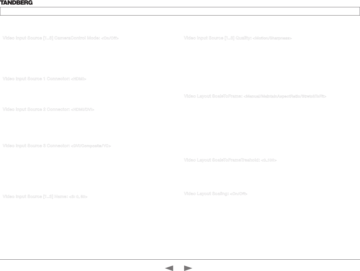
D14324.04—DECEMBER 2009 42
Profile series with Codec C60 Administrator Guide
Contents Introduction Getting started About the menus The settings menu Settings Library Cameras Appendices Contact us
Video Input Source [1..3] CameraControl Mode: <On/Off>
Determines whether or not the camera control should be enabled for the specific video input source.
Addresses the specific video input source.
On: Set to On to enable camera control for the camera connected to the selected video input connector.
Off: Set to Off to disable camera control for the camera connected to the selected video input connector.
Example: Video Input Source 1 CameraControl Mode: On
Video Input Source 1 Connector: <HDMI>
Select which video input connector to be active on connector group 1
HDMI: Select HDMI when you want to use the HDMI 1 connector as input
Example: Video Input Source 1 Connector: HDMI
Video Input Source 2 Connector: <HDMI/DVI>
Select which video input connector to be active on connector group 2
HDMI: Select HDMI when you want to use the HDMI 2 connector as input
DVI: Select DVI-I when you want to use the DVI-I 3 connector as input
Example: Video Input Source 2 Connector: HDMI
Video Input Source 3 Connector: <DVI/Composite/YC>
Select which video input connector to be active on connector group 3
DVI: Select DVI-I when you want to use the DVI-I 3 connector as input.
YC: Select YC when you want to use the S-Video (YC) input. Connect the S-Video input to the connector
marked as Y/Comp and C. NOTE! This configuration is not supported in version 1.
Composite: Select Comp when you want to use the Composite input. Connect the Composite input to the
connector marked
Example: Video Input Source 3 Connector: DVI
Video Input Source [1..3] Name: <S: 0, 50>
Customizable name of the connector group. Enter the name of the video input source 1-3.
Format: String with a maximum of 50 characters.
Example: Video Input Source 1 Name: “”
Video Input Source [1..3] Quality: <Motion/Sharpness>
When encoding and transmitting video there will be a tradeoff between high resolution and high framerate.
For some video sources it is more important to transmit high framerate than high resolution and vice versa.
The Quality setting specifies whether to give priority to high frame rate or to high resolution for a given
source. Addresses the selected video input connector.
Motion: Gives the highest possible framerate. Used when there is a need for higher frame rates, typically
when a large number of participants are present or when there is a lot of motion in the picture.
Sharpness: Gives the highest possible resolution. Used when you want the highest quality of detailed
images and graphics.
Example: Video Input Source 1 Quality: Motion
Video Layout ScaleToFrame: <Manual/MaintainAspectRatio/StretchToFit>
Defines what to do if the aspect ratio of a video input source doesn’t match the aspect ratio of the
corresponding image frame in a composition. For example if you have a 4:3 input source (like XGA) to be
displayed on a 16:9 output (like HD720).
Manual: If the difference in aspect ratio between the video input source and the target image frame is less
than the ScaleToFrameThrshold configuration (in percent), the image is stretched to fit. Unless the system
will maintain the original aspect ratio.
MaintainAspectRatio: Will maintain the aspect ratio of the input source, and fill in black in the rest of the
frame (letter boxing or pillar boxing).
StretchToFit: Will stretch (horizontally or vertically) the input source to fit into the image frame.
Example: Video Layout ScaleToFrame: MaintainAspectRatio
Video Layout ScaleToFrameTreshold: <0..100>
Only applicable if the ScaleToFrame configuration is set to manual. If the difference in aspect ratio between
the video input source and the target image frame is less than the ScaleToFrameThrshold configuration (in
percent), the image is stretched to fit. Unless the system will maintain the original aspect ratio.
Example: Video Layout ScaleToFrameTreshold: 5
Video Layout Scaling: <On/Off>
Defines whether the system should automatically adjust aspect ratio for images or frames when it differs
between the image and the frame it is to be placed in.
On: Let the system automatically adjust aspect ratio.
Off: Do not do any aspect ratio changes automatically.
Example: Video Layout Scaling: On
The Video settings, continued... The Video settings, continued...
Contents
Introduction
Getting started
About the menus
The Settings menu
The Settings library
Cameras
Appendices
Contact us
The Settings library
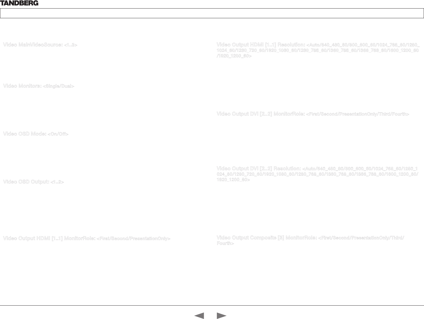
D14324.04—DECEMBER 2009 43
Profile series with Codec C60 Administrator Guide
Contents Introduction Getting started About the menus The settings menu Settings Library Cameras Appendices Contact us
Video MainVideoSource: <1..3>
Define which video input source shall be used as the main video source. The input source is configured to a
video input connector.
Range: 1-3 video sources
Example: Video MainVideoSource: 1
Video Monitors: <Single/Dual>
The codec can be used with more than one monitor and this setting lets you set the codec’s monitor layout
mode to Single or Dual.
Single: The same layout is shown on all monitors.
Dual: The layout is distributed on two monitors.
Example: Video Monitors: Single
Video OSD Mode: <On/Off>
The Video OSD (On Screen Display) Mode lets you define whether or not information and icons on screen
should be displayed.
On: Set to On to display the on screen menus, icons and indicators (microphone on/off, encryption on/off).
Off: Set to Off to hide the on screen menus, icons and indicators (microphone on/off, encryption on/off).
Example: Video OSD Mode: On
Video OSD Output: <1..2>
The Video OSD (On Screen Display) Output lets you define which monitor should display the on screen
menus, information and icons. By default the OSD output is displayed on the first monitor.
If you have a single monitor and you cannot see any OSD on the monitor: If the OSD output has been set to
the second monitor and the second monitor is not connected, then you cannot see any menus, information
or icons on the screen. To move the OSD output to the first monitor press the following shortcut sequence
on the remote control. Press the Disconnect key followed by: * # * # 0 x # (where x is output 1 or 2).
Example: Video OSD Output: 1
Video Output HDMI [1..1] MonitorRole: <First/Second/PresentationOnly>
The monitor role describes what video stream will be shown on the monitor connected to the output
connector. Applicable only if the “Video > Monitors” configuration is set to dual.
First: Show main video stream.
Second: Show presentation video stream if active, or other participants.
PresentationOnly: Show presentation video stream if active, and nothing else.
Example: Video Output HDMI 1 MonitorRole: First
The Video settings, continued... The Video settings, continued...
Video Output HDMI [1..1] Resolution: <Auto/640_480_60/800_600_60/1024_768_60/1280_
1024_60/1280_720_60/1920_1080_60/1280_768_60/1360_768_60/1366_768_60/1600_1200_60
/1920_1200_60>
Select the preferred resolution for the monitor connected to HDMI video output. This will force the selected
resolution on the monitor.
Auto: The system will automatically try to set the optimal resolution based on negotiation with the connected
monitor.
Range: 640x480@60p, 800x600@60p, 1024x768@60p, 1280x1024@60p, 1280x720@60p,
1920x1080@60p, 1280x768@60p, 1360x768@60p, 1366x768@60p, 1600x1200@60p, 1920x1200@60p
Example: Video Output HDMI 1 Resolution: 1920_1080_60
Video Output DVI [2..2] MonitorRole: <First/Second/PresentationOnly/Third/Fourth>
The monitor role describes what video stream will be shown on the monitor connected to the output
connector. Applicable only if the “Video > Monitors” configuration is set to dual.
First: Show main video stream.
Second: Show presentation video stream if active, or other participants.
PresentationOnly: Show presentation video stream if active, and nothing else.
Example: Video Output DVI 2 MonitorRole: Second
Video Output DVI [2..2] Resolution: <Auto/640_480_60/800_600_60/1024_768_60/1280_1
024_60/1280_720_60/1920_1080_60/1280_768_60/1360_768_60/1366_768_60/1600_1200_60/
1920_1200_60>
Select the preferred resolution for the monitor connected to DVI-I video output. This will force the selected
resolution on the monitor.
Auto: The system will automatically try to set the optimal resolution based on negotiation with the connected
monitor.
Range: 640x480@60p, 800x600@60p, 1024x768@60p, 1280x1024@60p, 1280x720@60p,
1920x1080@60p, 1280x768@60p, 1360x768@60p, 1366x768@60p, 1600x1200@60p, 1920x1200@60p
Example: Video Output DVI 2 Resolution: 1024_768_60
Video Output Composite [3] MonitorRole: <First/Second/PresentationOnly/Third/
Fourth>
The monitor role describes what video stream will be shown on the monitor connected to the output
connector. Applicable only if the monitor configuration is set to dual or quadruple.
First: Show main video stream.
Second: Show presentation video stream if active, or other participants.
PresentationOnly: Show presentation video stream if active, and nothing else.
Third: Use for remote participants (only for quadruple monitor setup).
Fourth: Use for remote participants (only for quadruple monitor setup).
Example: Video Output Composite 3 MonitorRole: First
Contents
Introduction
Getting started
About the menus
The Settings menu
The Settings library
Cameras
Appendices
Contact us
The Settings library
D14324.04—DECEMBER 2009 44
Profile series with Codec C60 Administrator Guide
Contents Introduction Getting started About the menus The settings menu Settings Library Cameras Appendices Contact us
Video Output Composite [3] Resolution: <PAL/NTSC>
Select the preferred resolution for the monitor connected to video output composite 3. This will force the
selected resolution on the monitor.
Range: PAL, NTSC
Example: Video Output Composite 3 Resolution: NTSC
Video Selfview: <On/Off>
The Video Selfview setting determines whether or not the main video source (selfview) should be displayed
on screen.
On: Set to On when you want selfview to be displayed on screen.
Off: Set to Off when you do not want selfview to be displayed on screen.
Example: Video Selfview: On
Video WallPaper: <None/Growing/Summersky/Custom>
The Video Wallpaper setting determines whether or not a background picture should be displayed on
screen when idle.
None: Set to None if you do not want a wallpaper to be displayed on screen.
Summersky, Growing: Select the wallpaper to be displayed on screen.
Custom: The custom wallpaper is uploaded from the web interface. Open a web browser and enter the IP
address of the codec. Select “Wallpaper” from the menu on top of the screen. Browse for the file and press
the “Upload” button. Toggle once between “None” and “Custom” wallpaper to make the change take effect.
See the Appendices section for further details about the web interface.
Example: Video Wallpaper: Summersky
The Video settings, continued...
Contents
Introduction
Getting started
About the menus
The Settings menu
The Settings library
Cameras
Appendices
Contact us
The Settings library
D14324.04—DECEMBER 2009 45
Profile series with Codec C60 Administrator Guide
Contents Introduction Getting started About the menus The settings menu Settings Library Cameras Appendices Contact us
Experimental Audio Equalizer [1..8] Section [1..6] a1: <S: 0, 32>
Sets the a1 coefficient for the given equalizer ID and section number.
The system has 8 user defined equalizers, each made up of 6 second order IIR sections. See the Appendix,
Equalizer section.
Example: Experimental Audio Equalizer 1 Section 1 a1: “0.0”
Experimental Audio Equalizer [1..8] Section [1..6] a2: <S: 0, 32>
Sets the a2 coefficient for the given equalizer ID and section number.
The system has 8 user defined equalizers, each made up of 6 second order IIR sections. See the Appendix,
Equalizer section.
Example: Experimental Audio Equalizer 1 Section 1 a2: “0.0”
Experimental Audio Equalizer [1..8] Section [1..6] b0: <S: 0, 32>
Sets the b0 coefficient for the given equalizer ID and section number.
The system has 8 user defined equalizers, each made up of 6 second order IIR sections. See the Appendix,
Equalizer section.
Example: Experimental Audio Equalizer 1 Section 1 b0: “0.0”
Experimental Audio Equalizer [1..8] Section [1..6] b1: <S: 0, 32>
Sets the b1 coefficient for the given equalizer ID and section number.
The system has 8 user defined equalizers, each made up of 6 second order IIR sections. See the Appendix,
Equalizer section.
Example: Experimental Audio Equalizer 1 Section 1 b1: “0.0”
Experimental Audio Equalizer [1..8] Section [1..6] b2: <S: 0, 32>
Sets the b2 coefficient for the given equalizer ID and section number.
The system has 8 user defined equalizers, each made up of 6 second order IIR sections. See the Appendix,
Equalizer section.
Example: Experimental Audio Equalizer 1 Section 1 b2: “0.0”
Experimental Audio Input Line [1..4] Equalizer ID: <1..8>
Select equalizer ID[1...8].
Example: Experimental Audio Input Line 1 Equalizer ID: 1
Experimental Audio Input Line [1..4] Equalizer Mode: <On/Off>
Determines whether or not the selected equalizer is enabled.
On: Use the selected equalizer
Off: No equalizer
Example: Experimental Audio Input Line 1 Equalizer Mode: Off
Experimental Audio Input Microphone [1..4] Channel: <Left/Right/Mono>
Defines whether the microphone input is a mono signal or part of a multichannel signal.
Left: The microphone input signal is the left channel of a stereo signal.
Right: The microphone input signal is the right channel of a stereo signal.
Mono: The microphone input signal is a mono signal.
Example: Experimental Audio Input Microphone 1 Channel: Mono
Experimental Audio Input Microphone [1..4] EchoControl HighPassFilter: <On/Off>
Set the microphone echo control high pass filter to on/off.
Example: Experimental Audio Input Microphone 1 EchoControl HighPassFilter: On
Experimental Audio Input Microphone [1..4] Equalizer ID: <1..8>
Select equalizer ID[1...8]
Example: Experimental Audio Input Microphone 1 Equalizer ID: 1
Experimental Audio Input Microphone [1..4] Equalizer Mode: <On/Off>
Determines whether or not the selected equalizer is enabled.
On: Use the selected equalizer
Off: No equalizer
Example: Experimental Audio Input Microphone 1 Equalizer Mode: Off
Experimental Audio Output Line [1..6] Equalizer ID: <1..8>
Select equalizer ID[1...8]
Example: Experimental Audio Output Line 1 Equalizer ID: 1
The Experimental menu, cont...
The Advanced configurations menu has an option called Experimental. The settings within this menu can
be used ‘as is’ and will not be documented.
NOTE! The Experimenal menu WILL change.
We recommend you visit the TANDBERG web site regularly for updated versions of the manual.
Go to: http://www.tandberg.com/docs
Contents
Introduction
Getting started
About the menus
The Settings menu
The Settings library
Cameras
Appendices
Contact us
The Settings library
D14324.04—DECEMBER 2009 46
Profile series with Codec C60 Administrator Guide
Contents Introduction Getting started About the menus The settings menu Settings Library Cameras Appendices Contact us
Experimental Audio Output Line [1..6] Equalizer Mode: <On/Off>
Determines whether or not the selected equalizer is enabled.
On: Use the selected equalizer
Off: No equalizer
Example: Experimental Audio Output Line 1 Equalizer Mode: Off
Experimental CapsetFilter: <S: 0, 32>
To be described.
Example: Experimental CapsetFilter: “”
Experimental CustomSoftbuttons State [1..2] Softbutton [1..5] Type: <NotSet/
MainSource/PresentationSource/CameraPreset/Actions/SpeedDial>
To be described.
Example: Experimental CustomSoftbuttons State 1 Softbutton 1 Type: NotSet
Experimental CustomSoftbuttons State [1..2] Softbutton [1..5] Value: <S: 0, 255>
To be described.
Example: Experimental CustomSoftbuttons State 1 Softbutton 1 Value: “”
Experimental Video OptimalDefinition Profile: <Normal/Medium/High>
Video quality is determined by a combination of resolution and frame rate and varies based on bandwidth.
Normal, Medium, High: See the Video optimal definition tables below.
Table 1: For systems supporting 1080p
w288p30 w448p30 w576p30 720p30 1080p30
Normal 256kbit/s 512 kbit/s 768 kbit/s 1152 kbit/s 2560 kbit/s
Medium 128kbit/s 384 kbit/s 512 kbit/s 768 kbit/s 1920 kbit/s
High 128kbit/s 256 kbit/s 512 kbit/s 768 kbit/s 1472 kbit/s
Table 2: For systems supporting 720p60
w144p60 w288p60 w448p60 w576p60 720p60
Normal 128kbit/s 512 kbit/s 1152 kbit/s 1472 kbit/s 2240 kbit/s
Medium 128kbit/s 384 kbit/s 768 kbit/s 1152 kbit/s 1472 kbit/s
High 128kbit/s 256 kbit/s 512 kbit/s 768 kbit/s 1152 kbit/s
Example: Experimental Video OptimalDefinition Profile: Normal
The Experimental settings, continued...
Contents
Introduction
Getting started
About the menus
The Settings menu
The Settings library
Cameras
Appendices
Contact us
The Settings library
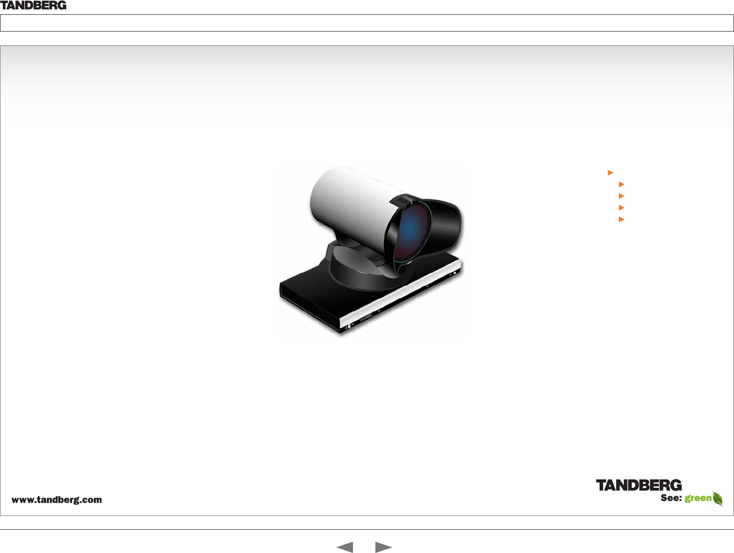
D14324.04—DECEMBER 2009 47
Profile series with Codec C60 Administrator Guide
Contents Introduction Getting started About the menus The settings menu Settings Library Cameras Appendices Contact us
Cameras
Chapter 8
In this chapter...
The PrecisionHD 1080p camera
Connecting the camera
Best view—Face recognition
Video output formats
Cameras in daisy chain
Your TANDBERG PrecisionHD 1080p
Camera has been designed to give you
many years of safe, reliable operation.
Additional information about the camera
is found in the TANDBERG PrecisionHD
1080p User Guide.
Contents
Introduction
Getting started
About the menus
The Settings menu
The Settings library
Cameras
Appendices
Contact us
Cameras
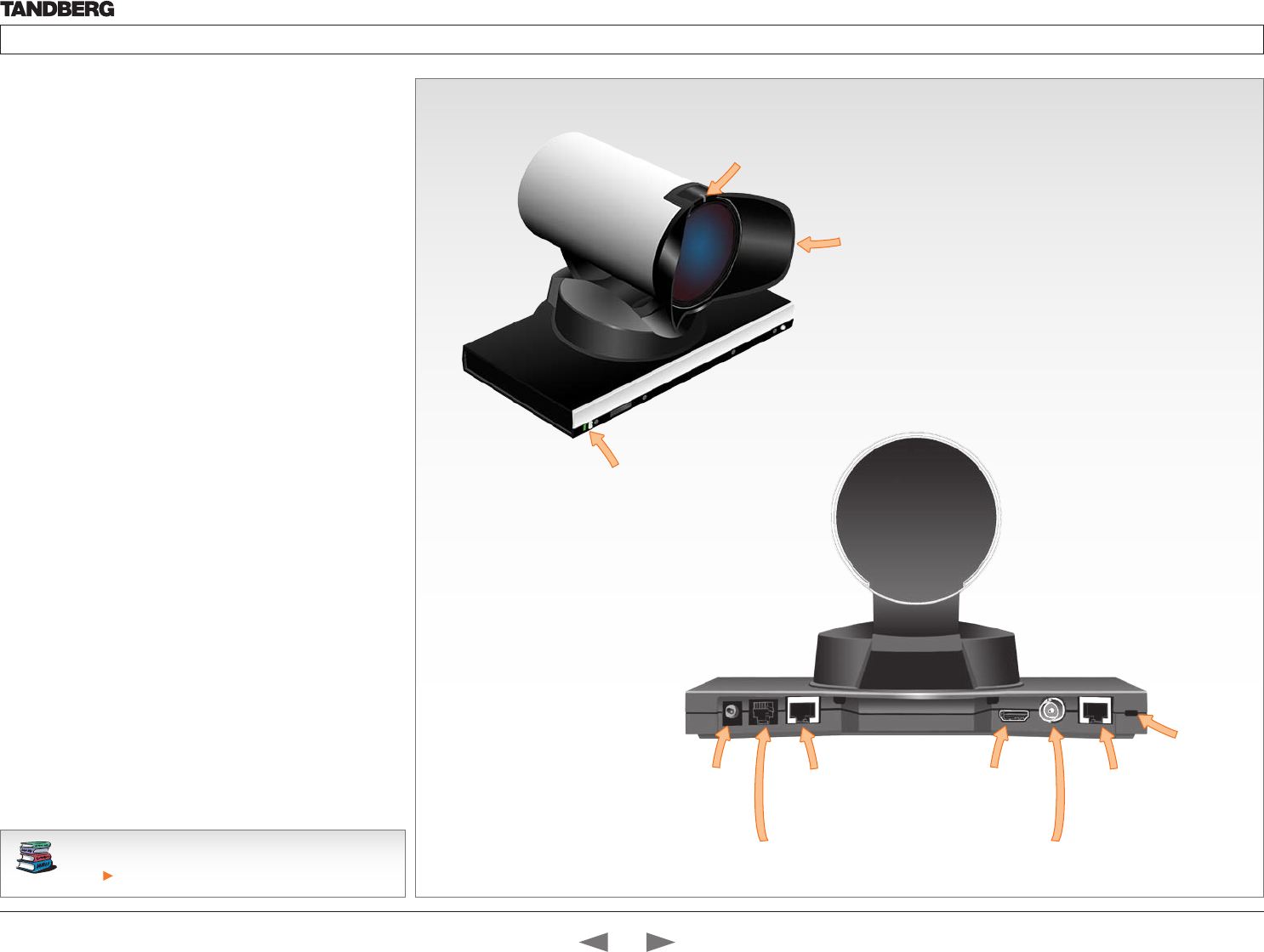
D14324.04—DECEMBER 2009 48
Profile series with Codec C60 Administrator Guide
Contents Introduction Getting started About the menus The settings menu Settings Library Cameras Appendices Contact us
See the TANDBERG PrecisionHD 1080p User Guide for
comprehensive information about the camera.
Go to: http://www.tandberg.com/docs
The PrecisionHD 1080p camera
Video out (HDMI, HD-SDI). For video signals, connect from the
video out on the camera to the video in on the codec.
Power and camera control. For power in and camera control,
connect from the camera control & power on the camera to
the Camera port on the codec. When the camera is used with
TANDBERG codecs power will be supplied through Camera Control
cable. When used with non-TANDBERG Codecs, you may have to
connect power separately.
HDMI and HD-SDI
• HDMI is the main source for video out when connected to Codec
C60. Maximum resolution is 1080p60.
• HD-SDI is the secondary source for video. Maximum resolution
is 1080p30.
• The HDMI and HD-SDI can be used simultaneously. The
maximum resolution is then 1080p30 if you want both to run with
the same resolution.
Kensington lock
The Kensington lock may be used to prevent the camera to be
moved from its place or to prevent theft.
Cascaded cameras
The sockets named Extra Camera Out and Power In are used when
connecting cameras in daisy chain.
• The first camera in the chain is powered up by the camera
control cable. The next cameras must use the 12V DC Power in.
• The daisy chained cameras are connected by using an extra
camera cable between the Extra Camera sockets.
Power Supply
Extra Camera Out and for Daisy Chaining
Camera Control HDMI Video Out Not Used
HD-SDI Out
HDMI and HD-SDI can be
used simultaneously.
The lens hood is detachable.
We recommend that you
mount it to prevent stray light
from disturbing your video
experience.
Just snap it on gently.
The orange LED illuminates while in a
call and flickers when there is an
incoming call.
Kensington lock
The green LED is continuously illuminated
when power is On, but it flickers when
receiving signals from the remote control.
NOTE: The green LED is hidden behind
the top grille on TANDBERG Profile 65”.
Disassemble the top grille to see the LED.
Contents
Introduction
Getting started
About the menus
The Settings menu
The Settings library
Cameras
Appendices
Contact us
Cameras
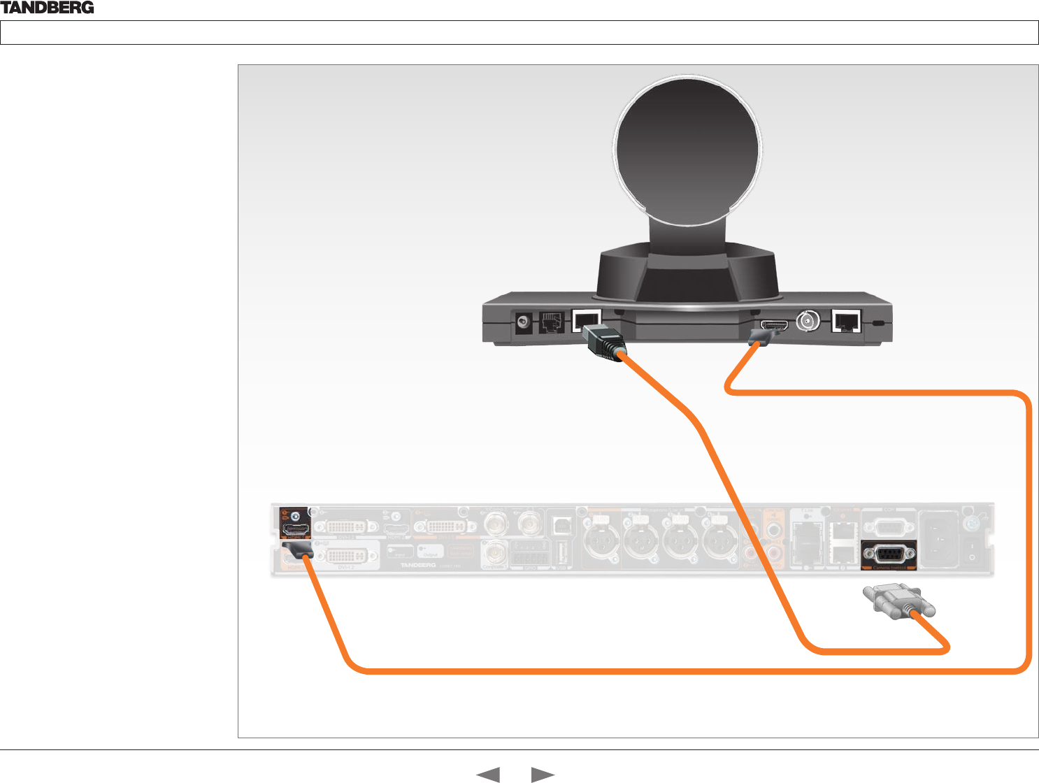
D14324.04—DECEMBER 2009 49
Profile series with Codec C60 Administrator Guide
Contents Introduction Getting started About the menus The settings menu Settings Library Cameras Appendices Contact us
Connecting HDMI HD Video out on camera to HDMI 1 In on the Codec.
HDMI and HD-SDI
can be used simultaneously.
VISCA™ is a trademark of Sony Corporation
The PrecisionHD 1080p
camera, cont...
Connecting the camera
The HDMI and HD-SDI can be used
simultaneously.
HDMI cable
The HDMI cable delivered with the camera is
5 meters.
Maximum length is 15 meter with a category 2
certified good quality HDMI cable.
HD-SDI cable
The HD-SDI cable must be purchased
separately. The maximum recommendable
length of HD SDI cable is 100 m.
Connect the camera control cable, RJ45
to RS-232. Visca™ protocol is supported.
Contents
Introduction
Getting started
About the menus
The Settings menu
The Settings library
Cameras
Appendices
Contact us
Cameras
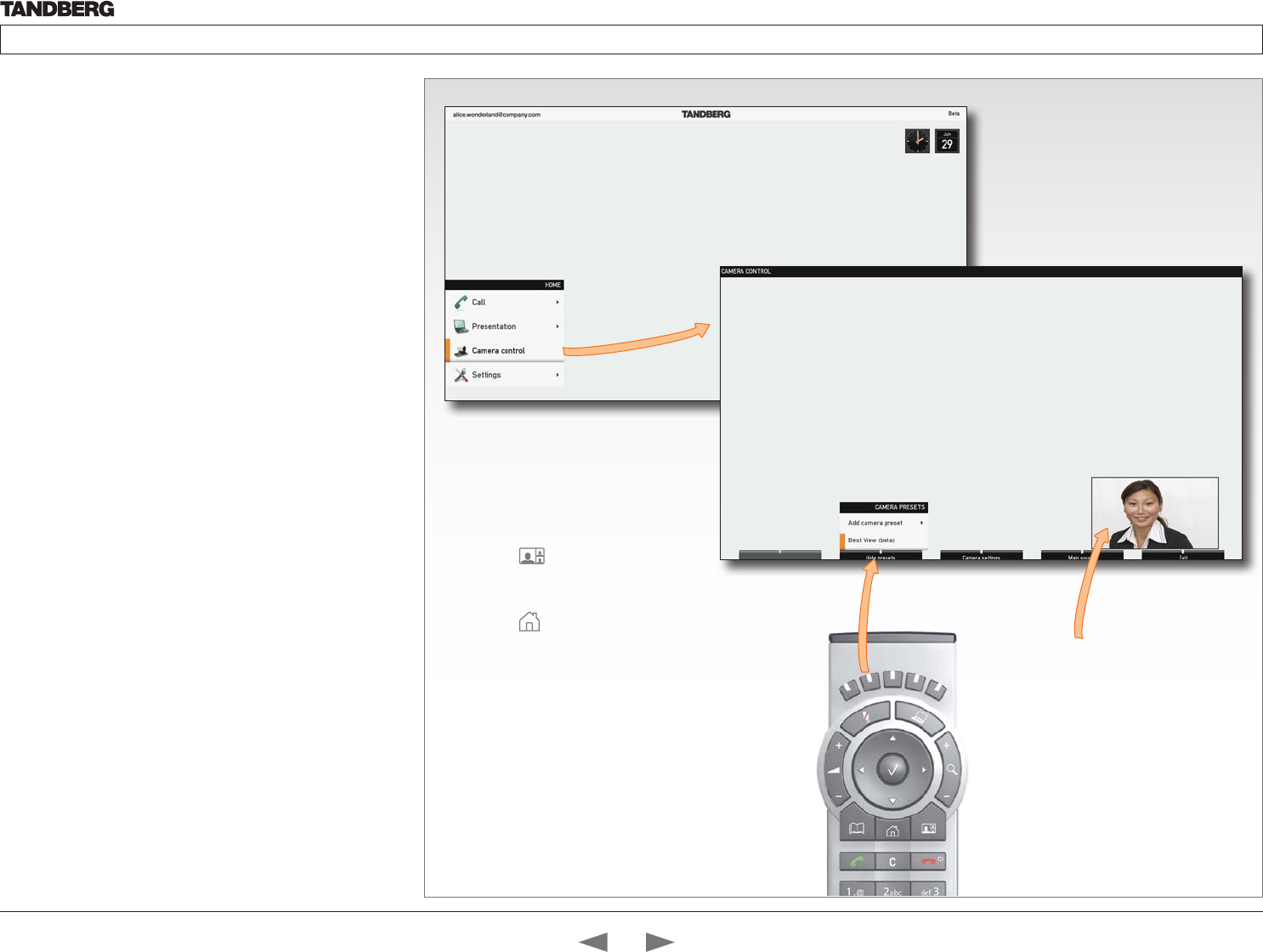
D14324.04—DECEMBER 2009 50
Profile series with Codec C60 Administrator Guide
Contents Introduction Getting started About the menus The settings menu Settings Library Cameras Appendices Contact us
The PrecisionHD 1080p camera,
cont...
Best view—Face recognition
This camera is capable of face recognition when used with
TANDBERG C60/C90 Codecs. Consequently, the functionality is
subject to change without prior notice in order to take advantage of
further developments.
NOTE: Observe that the Best view feature is still a preview feature.
The face recognition system aims to search for faces in order to
optimize the picture frame, hence the name Best view. Once a face
or group of faces has been detected camera zoom and camera angle
will be changed accordingly to obtain an optimal presentation on the
screen.
Read this before using Best view:
• The Best view optimization process may take up to 5 seconds.
• The detection of faces works better when people look towards the
camera.
• The area from the eyebrows down to just below the lips should be
uncovered.
• Beard is normally not a problem.
Select Selfview to be shown.
Using Best view
Note that Best view works with TANDBERG
C60/C90 Codecs only!
1. Press the Layout key on the remote
control to display the Layout menu. Select
Selfview to be shown as required.
2. Press the Home key on the remote
control to display the Home menu and
select Camera control
3. Press the second soft button on the remote
control to display the Preset menu. Select
Best view from the menu press the OK key
on the remote control to start the Best view
optimization process.
4. Look towards the camera for about five
seconds. The system will look for human
faces and adjust the zoom and camera
angle to obtain a best fit.
Contents
Introduction
Getting started
About the menus
The Settings menu
The Settings library
Cameras
Appendices
Contact us
Cameras
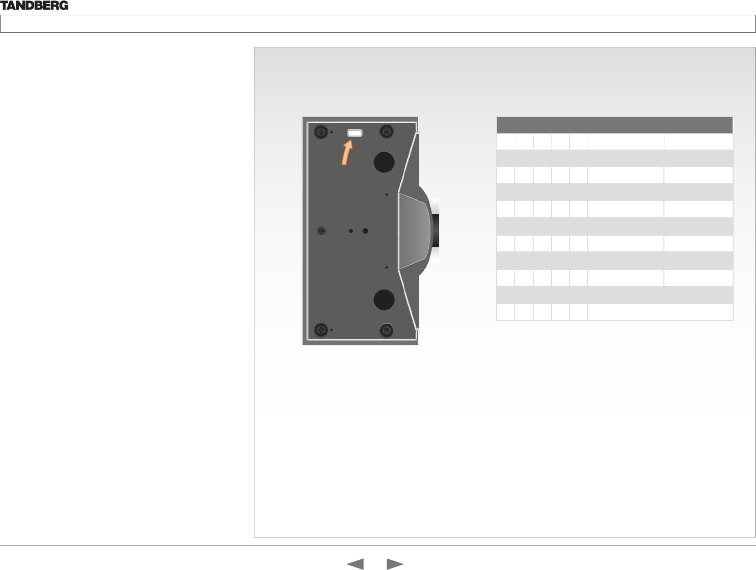
D14324.04—DECEMBER 2009 51
Profile series with Codec C60 Administrator Guide
Contents Introduction Getting started About the menus The settings menu Settings Library Cameras Appendices Contact us
The PrecisionHD 1080p camera,
cont...
Video output formats
This section describes the video output formats for the TANDBERG
PrecisionHD 1080p camera.
DIP switch settings for video output formats
The DIP switch sets the video output format for the camera. The DIP
switch is on the underside of the camera. The default setting is Auto.
See the table to the right.
• Maximum resolution for HDMI is 1080p60
• Maximum resolution for HD-SDI is 1080p30.
Line voltage frequency
The camera will automatically detect the line voltage frequency when it
is 50 or 60 Hz. If there is a different line voltage, you can set the video
output format to a specific value (use the DIP switches) to override the
auto frequency detection.
Set the PrecisionHD 1080p DIP switch (country specific setting):
• 50Hz: 00011, gives 1080p50 (720p50 for HD-SDI)
• 60Hz: 00100, gives 1080p60 (720p60 for HD-SDI)
DIP Switch table for video formats
1 2 3 4 5 HDMI HD-SDI
0 0 0 0 0 Auto
0 0 0 0 1 1920x1080p25 1920x1080p25
0 0 0 1 0 1920x1080p30 1920x1080p30
0 0 0 1 1 1920x1080p50 1280x720p50
0 0 1 0 0 1920x1080p60 1280x720p60
0 0 1 0 1 1280x720p25 1280x720p25
0 0 1 1 0 1280x720p30 1280x720p30
0 0 1 1 1 1280x720p50 1280x720p50
0 1 0 0 0 1280x720p60 1280x720p60
0 1 0 0 1 Software control
The DIP switch
1
0
The table shows the different settings available for the HDMI and
the HD-SDI outputs.
Auto: Camera negotiates format over HDMI. HD-SDI tracks HDMI
and defaults to 1080p30 in absence of HDMI sync.
Software: For more on the Software control setting, read about
video mode selections in the TANDBERG PrecisionHD 1080p User
Guide.
Underside side of the TANDBERG
PrecisionHD 1080p camera
Contents
Introduction
Getting started
About the menus
The Settings menu
The Settings library
Cameras
Appendices
Contact us
Cameras
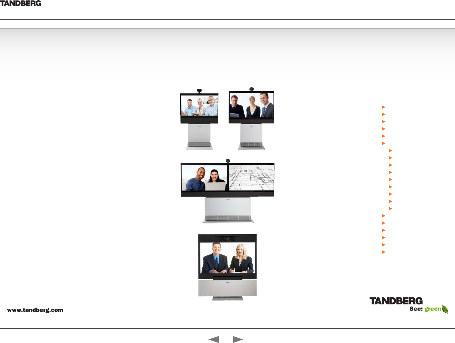
D14324.04—DECEMBER 2009 52
Profile series with Codec C60 Administrator Guide
Contents Introduction Getting started About the menus The settings menu Settings Library Cameras Appendices Contact us
Appendices
Chapter 7
In this chapter...
General room guidelines
Meeting room setup
Remote control TRC5
Password protection
Startup scripts
The web interface
System info page
Software upgrade
Advanced configuration
Custom wallpaper
Making a call
Upload certificate
XML files
Logs
Add release key
The DNAM
Supported RFCs in SIP
China RoHS
CE Declaration
Dimensions
Technical specifications
Contents
Introduction
Getting started
About the menus
The Settings menu
The Settings library
Cameras
Appendices
Contact us
Appendices

D14324.04—DECEMBER 2009 53
Profile series with Codec C60 Administrator Guide
Contents Introduction Getting started About the menus The settings menu Settings Library Cameras Appendices Contact us
General room guidelines
The physical conditions
When building a video meeting room, or using an existing room for
video meetings there are a few guidelines to consider.
Lighting
• The illumination should be distributed evenly in the room to obtain
low contrast
• The ideal light intensity is a little higher than in an ordinary meeting
room. Typically, the luminous intensity should be 800–1400Lux,
measured at the table with an incident light meter
Seating area and table
• The seating area and table should be non-shiny and non-patterned
• The seating area should allow all participants to see the monitor
Walls
• The color of the wall should be in good contrast to skin tonality.
Light blue is a complementary color to skin tonality, it gives a good
contrast and is commonly used
• Acoustically reflective surfaces (such as glass or concrete) should
be covered with curtains or sound treatment
Audio
• The Noise Floor (the sum of all the noise sources) should be less
than max 35dBA
• The reverberation time should be 0,3 to 0,5 seconds
Ventilation
• When having a TANDBERG Profile system installed the
requirements for ventilation is higher than in an ordinary meeting
room. See the Technical specifications section in the Appendices
to find the output values for your TANDBERG Profile.
• Keep in mind the Noise Floor (see Audio)
• Velocity creates noise, therefore keep velocity of air low
The room equipment
When placing and using the room equipment there are a few
recommendations and guidelines to consider.
The microphone
• The microphones should be evenly distributed on the table. Avoid
positions where they can be hidden behind obstacles like laptop,
projector or other equipment placed on the table
• Do not place a microphone close to noisy equipment like computer
and projector fans, power outlets or similar arrangements on the
table. The microphone will pick up noise from these arrangements
quite strongly.
The camera
• The camera should be able to “see” all participants in the room.
Use the pan, tilt and zoom features to adjust the picture
The PC
• PC’s placed on the table should not cover the microphones as this
will reduce the audio quality at the far end
Position of the system
• Position the video system in such a way that all participants
attending the meeting are visible to the far end
• If appropriate, the far end should be able to see people entering or
leaving the room
The document camera
• The document camera should be close to the chair person or a
designated controller of the document camera for ease of use
Make sure this person is visible on screen while carry out the task
Other peripherals
• Arrange all the peripherals so that the chair person can reach each
of them to point, change the display, DVD, and still be fully visible
on screen while carry out the task
Environmental considerations
This section explains how to carry out basic adjustments and simple
tests to ensure that you send and receive the best possible image and
audio quality when using your system.
Iris control and lighting
By default the system camera will use an automatic iris to compensate
for changes in lighting. In addition to this feature, you may further
assist the system to maintain the best possible image quality by
paying special attention to environmental lighting and background
colors as described below.
Remember the system will send live images of both yourself and your
immediate surroundings.
• Avoid direct sunlight on the subject matter i.e. yourself, the
background or onto the camera lens as this will create harsh
contrasts
• Avoid placing the seatings in front of a window with natural
daylight, as this will make the faces of people very dark
• If light levels are too low you may need to consider using artificial
lighting. As described above, direct illumination of the subject
matter and camera lens should be avoided
• When using artificial lighting, daylight type lamps will produce the
most effective results. Avoid colored lighting
• Indirect light from shaded sources or reflected light from pale walls
often produces excellent results
• Avoid harsh side lighting or strong light from above. Strong sunlight
from a window or skylight may put part or all of the subject matter
in shadow or cause silhouetting
Loudspeaker volume
The audio system will use the Digital Natural Audio Module (DNAM)
which is integrated in the system. The volume of the audio is controlled
by the Volume key on the remote control.
Contents
Introduction
Getting started
About the menus
The Settings menu
The Settings library
Cameras
Appendices
Contact us
Appendices
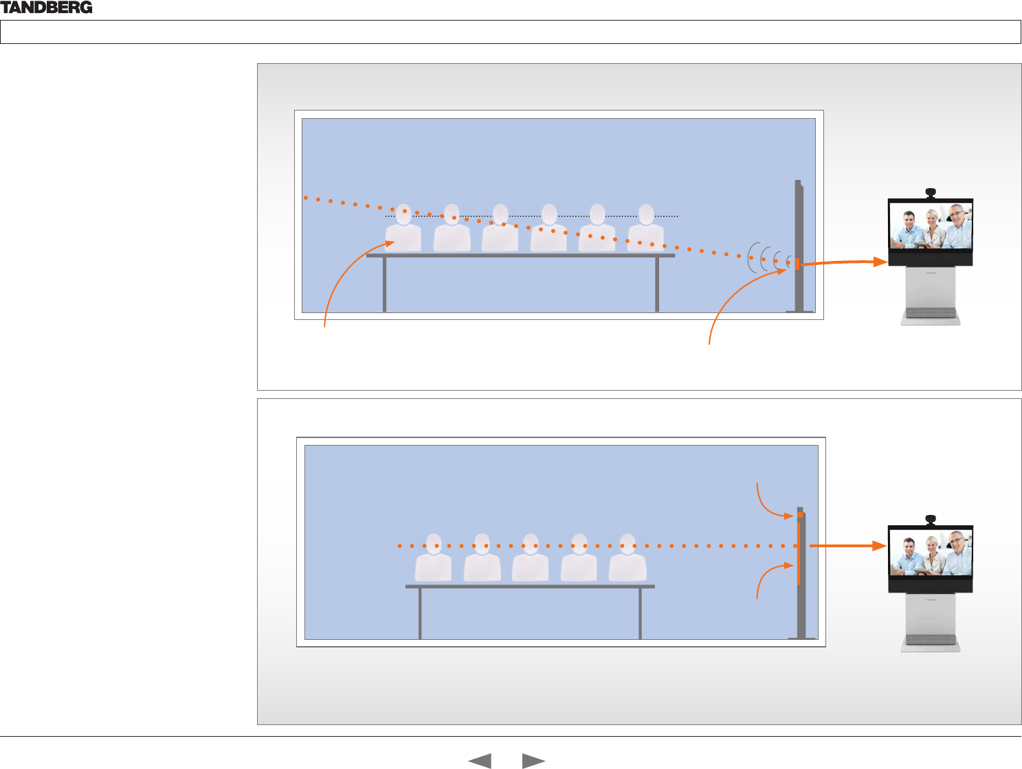
D14324.04—DECEMBER 2009 54
Profile series with Codec C60 Administrator Guide
Contents Introduction Getting started About the menus The settings menu Settings Library Cameras Appendices Contact us
The audio quality
To keep the high quality audio, make sure there is
free sight to the speaker module
• There should be free sight between the ears
of the participants and the system speaker
module
• Participant sitting too far away from the video
system may not have the same audio quality as
the others.
Natural communication
Making eye contact with the far end participants
will improve the natural communication between
the people
• Adjust the camera view (using zoom in/out) to
allow the participants to be shown in full size
on screen, and to keep eye contact with each
other at the same eye level
• If the participants are sitting too close to
the monitor the camera will “look down” at
the participants. This may not give a good
presentation of the participants at the far end.
The best audio quality to all participants
Making eye contact
HD Camera
This participant may not have
the same audio quality as the
others
Monitor
The far end participants
Eye height
Ear height
The line of free sight
Speaker module
Contents
Introduction
Getting started
About the menus
The Settings menu
The Settings library
Cameras
Appendices
Contact us
Appendices
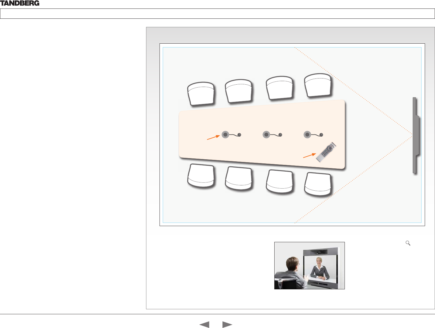
D14324.04—DECEMBER 2009 55
Profile series with Codec C60 Administrator Guide
Contents Introduction Getting started About the menus The settings menu Settings Library Cameras Appendices Contact us
Guidelines for meeting room setup
For team collaboration rooms, team meeting rooms and showroom
floor.
General recommendations for the room layout
To fully utilize the experience there are some guidelines you should
consider.
The distance between the table and the video system
• The monitors are full HD LCD display and requires some distance
to the table to allow all participants to see a clear picture on screen
• The 42”/52” monitors requires minimum 1,5 m / 59 inch
• The 65” monitor requires 2–2,5 m / 78–98 inch
• The camera should capture all participants in the room.
• The camera angle at maximum zoom out is 72°.
• Adjust the camera view (using zoom in/out) to allow the
participants to be shown in full size on screen, and to keep eye
contact with each other at the same eye level
• If the participants are sitting too close to the monitor the camera
will “look down” at the participants. This may not give a good
presentation of the participants at the far end.
The speaker module
• The speaker module requires a minimum of 1,5 m / 59 inch free
space in front
• There should be free sight between the system speaker module
and the ear of the participants.
The microphones
• The microphones should be evenly distributed on the table
• Avoid positions where they can be hidden behind obstacles like
laptop or other equipment placed on the table
• Do not place a microphone close to noisy equipment like computer
and projector fans, power outlets or similar arrangements on the
table. The microphone will pick up noise from these arrangements
quite strongly.
Microphones
Remote
control
4
7
ghi
pqrs
6
#
abc/123
9
1
.@
5
0
8
jkl
tuv
2
abc 3
def
mno
wxyz
Camera view
- with max zoom
out
Adjust the camera view
Press the Zoom +/– button on the
remote control to adjust the picture
on screen.
Adjust the camera view to allow the
participants to have eye contact with
each other at the same eye level.
Contents
Introduction
Getting started
About the menus
The Settings menu
The Settings library
Cameras
Appendices
Contact us
Appendices
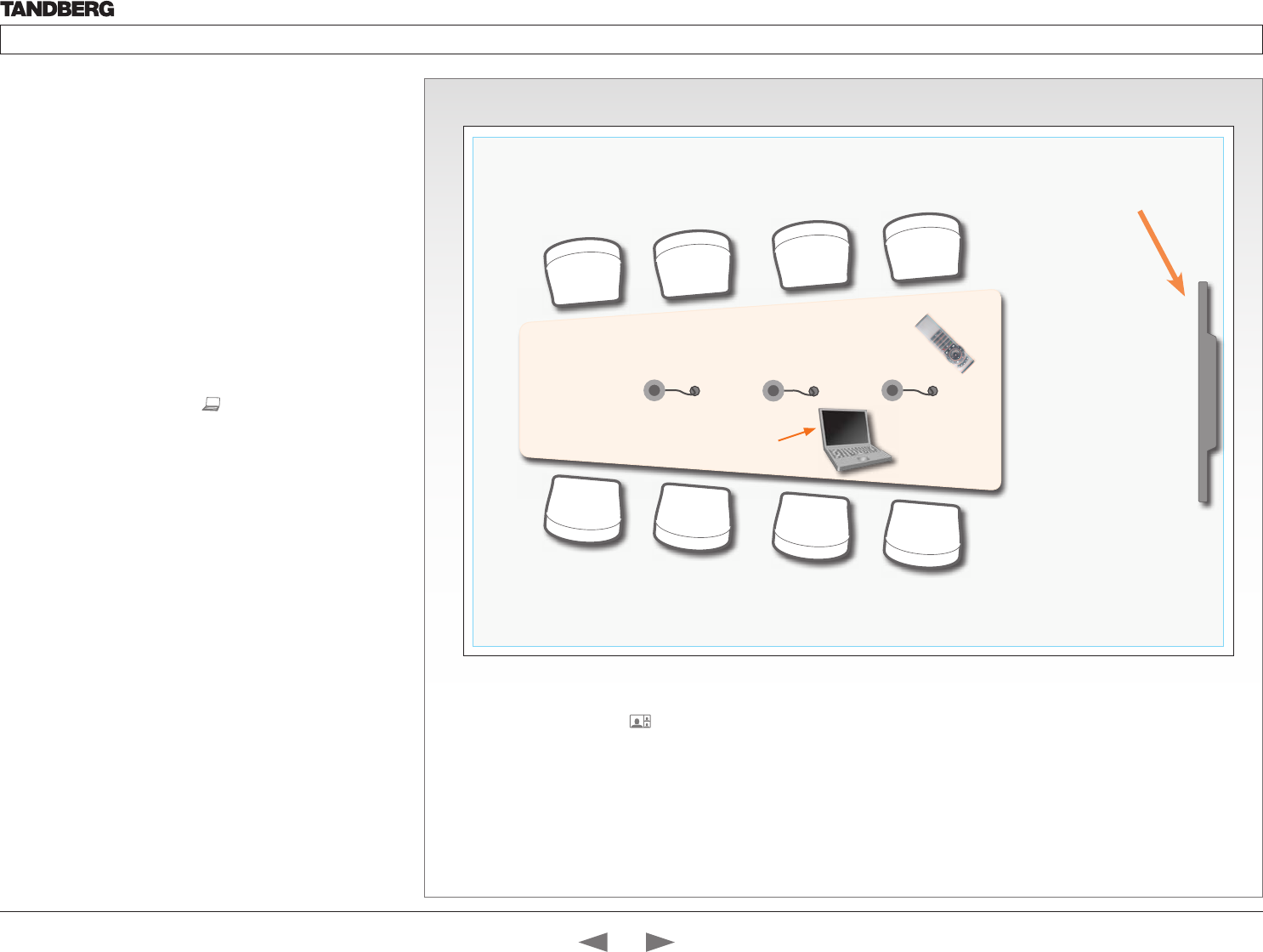
D14324.04—DECEMBER 2009 56
Profile series with Codec C60 Administrator Guide
Contents Introduction Getting started About the menus The settings menu Settings Library Cameras Appendices Contact us
PC
4
7
ghi
pqrs
6
#
abc/123
9
1
.@
5
0
8
jkl
tuv
2
abc 3
def
mno
wxyz
Sharing a PC presentation
Dual video stream
With dual video stream you can view two different live video streams
simultaneously, the main video and one additional source. This could
for example be both a PC presentation and the person who gives the
presentation.
If one of the video systems does not support Dual Video Stream, no
second video stream will be established and the PC presentation will
be shown as the main video.
Sharing the presentation
1. Make sure the PC do not cover any of the microphones as this will
reduce the audio quality at the far end
2. Locate the DVI cable and connect the PC to the video system
3. When pressing the PC button ( ) on the remote control the
default presentation source is activated.
The DVI/VGA input is compliant with VESA Extended Display
Identification Data (EDID) and will be able to notify the PC of the
supported output formats.
Troubleshooting if the presentation does not show
• On most PC’s you must press a special key combination to switch
the PC image from the PC screen to the video screen
• Make sure the connector used for PC presentation is configured as
the default presentation source.
Go to: Home > Settings > Advanced > Advanced configuration
> Video > DefaultPresentationSource (the default value is 3,
and corresponds to Home > Settings > Advanced > Advanced
configuration > Video > Input > Source 3)
• Make sure your PC is set to activate your VGA output
Other presentation sources
You can also connect other presentation sources like:
• DVD
• Document camera
Shows the PC presentation
and the participants
The screen layout
Press the Layout button on the
remote control to select a suitable
layout on screen.
The default layout when showing
a PC presentation is designed to
allow the participants to keep eye
contact with each other during the
presentation.
Contents
Introduction
Getting started
About the menus
The Settings menu
The Settings library
Cameras
Appendices
Contact us
Appendices
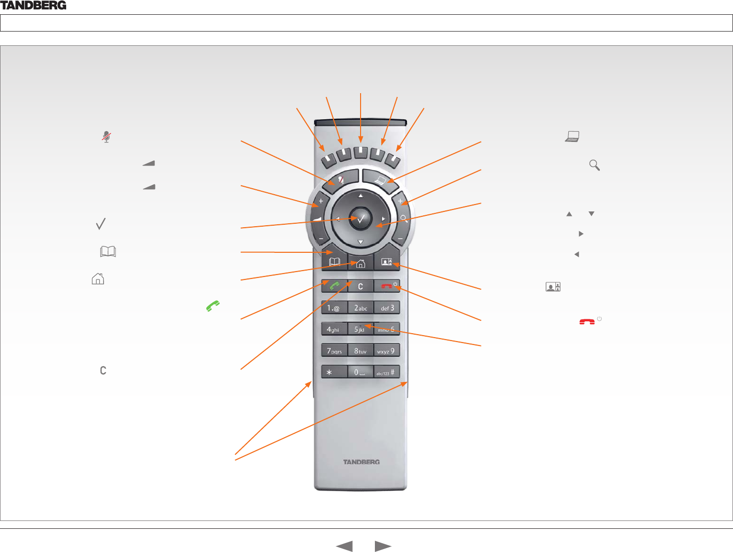
D14324.04—DECEMBER 2009 57
Profile series with Codec C60 Administrator Guide
Contents Introduction Getting started About the menus The settings menu Settings Library Cameras Appendices Contact us
TANDBERG Remote Control TRC5
Microphone: Press the key to toggle the microphones on/off.
Volume: Press the + or – on the key to adjust the codec
volume.
Mute: Press the – on the key to mute the volume
during an incoming call.
OK/Select: Press the key to confirm your choice or selection.
Phone book: Press the key to display the local Phone book.
Home: Press the key to key to show the menu on screen.
Call: Using the key:
INITIATE A CALL: Select a name from the Phone book or enter the
name, number or URI and press the Call key to initiate the call.
SHORTCUT TO RECENT CALLS: Use the Call key as a shortcut to
Recent Calls when the Call menu is not visible.
Clear: Press the key to remove characters in a text field.
Function keys: Represents shortcuts and advanced
functions. Each key reflects a soft key on screen.
Presentation: Press the key to show/hide a presentation.
Zoom: Press the + or – on the key to zoom the camera in
and out.
Arrows:
• Up/Down: Use the and arrow keys to navigate in the
menu.
• Arrow Right: Press the arrow key to expand the selected
menu item or to move to the right in a text field.
• Arrow Left: Press the arrow key to go one step back in
the menu or to move to the left in a text field.
Layout: Press the key to display the Layout menu, then
select a view in the menu.
End call/Standby: Press the key to end a call, or when
idle, press and hold the key to go into standby mode.
Alphanumeric keypad: Use the keypad in the same way as you
would use a cellular phone.
• 0-9, a-z, period (.), @, space, *: Press a key repeatedly to
toggle between the options displayed on each key.
• abc/123 #: Press the # key to toggle between touch tones
mode (long press), lower case characters and numbers.
Waking up the system
Grab the remote control and make sure your hand
touches the rubber line sensors going along both
sides of the remote control.
or: Touch any key on the remote control.
IR transmitter range (DIP switch setting)
The IR transmitter has a short and long range. Open the battery
cover and remove the batteries to set the DIP switch.
• Short range (1 m): Move the DIP switch down.
• Longer range: Move the DIP switch up.
Contents
Introduction
Getting started
About the menus
The Settings menu
The Settings library
Cameras
Appendices
Contact us
Appendices

D14324.04—DECEMBER 2009 58
Profile series with Codec C60 Administrator Guide
Contents Introduction Getting started About the menus The settings menu Settings Library Cameras Appendices Contact us
Setting the codec administrator password
Do the following to define the administrator password on the codec:
1. Connect to the codec through the network or the serial data
port, using a command line interface (ssh, telnet or scp)
2. Login to the codec with user name (admin) and no password.
3. Run the following API command and enter a password:
xCommand SystemUnit AdminPassword Set
Password: “****”
4. The password format is a string with 0–255 characters.
5. Reboot the codec.
Password protection of the web interface
The web interface is password protected with the same user name
and password as defined for the codec.
NOTE! To activate the administrator password on the web interface,
after having defined or changed the administrator password, a
reboot of the codec is required. Without a reboot the administrator
password will only apply when you login to the codec.
Login to the codec or the web interface
• You can login to the codec with the user name and password,
either from a web interface or from a command line interface.
You will need to enter both the user name and password.
• The user name is admin, and cannot be changed.
How to deactivate the administrator password
1. Connect to the codec through the network, using a command
line interface (ssh, telnet or scp).
2. Login to the codec with the required user name (admin) and
password.
3. Run the following API command with a blank password:
xCommand SystemUnit AdminPassword Set
Password: ““
4. Reboot the codec.
Setting the menu password
Do the following to define a password for the Advanced menus:
1. Open the menu on screen and go to: Home > Settings >
Advanced > Change password.
2. The password is a string with 0–255 characters.
3. Enter the password and press Save.
Login to the Advanced menu
When a password is set, the password is required to get access to
the Advanced menu on screen.
How to change the menu password
1. To change the password, go to: Home > Settings > Advanced
> Change password in the menu.
2. Enter the new password in the Set password menu.
3. Press Save to save the new password.
How to deactivate the menu password
1. To change the password, go to: Home > Settings > Advanced
> Change password in the menu.
2. Leave the text field empty in the Set password menu.
3. Press Save to save the blank password. This will deactivate the
menu password.
Password protection
The system can be password protected in three
ways:
1. The Advanced menus can be password
protected with a menu password.
2. The codec can be password protected with an
administrator password.
3. The web interface is password protected with
the same administrator password as for the
codec. NOTE! Requires a reboot of the codec.
NOTE! When a new password has been defined
make sure you save a copy of the password in a
safe place.
Contact your TANDBERG representative if you have
forgotten the password.
Contents
Introduction
Getting started
About the menus
The Settings menu
The Settings library
Cameras
Appendices
Contact us
Appendices

D14324.04—DECEMBER 2009 59
Profile series with Codec C60 Administrator Guide
Contents Introduction Getting started About the menus The settings menu Settings Library Cameras Appendices Contact us
Adding a startup script
The startup script can be used to execute certain commands from
the API during boot up. To enable this feature one must log in to the
codec as root and follow the below points.
Login to the codec
1. Connect to the codec through the network, using a command
line interface (ssh, telnet or scp) and login as root
2. Make a user directory using the following command: “mkdir /
user/scripts.d”
3. Put an executable file (permission must be changed to
executable) in this directory.
Example of such a file:
About the startup script file
• The file must start with the following sequence:
#!/usr/bin/env tsh
• The file can contain any xCommand or xConfiguration command
• The system will execute the commands/configurations in
sequence.
• The file can have any name as long as it is placed in this
directory.
• For multiple commands you must use Unix end of line (LF).
Windows end of line will not work.
Startup script
You can add a startup script on the codec to
execute certain commands from the API during
boot up.
#!/usr/bin/env tsh
xCommand Audio LocalInput Update InputId: 1 MixerMode:Fixed
Contents
Introduction
Getting started
About the menus
The Settings menu
The Settings library
Cameras
Appendices
Contact us
Appendices
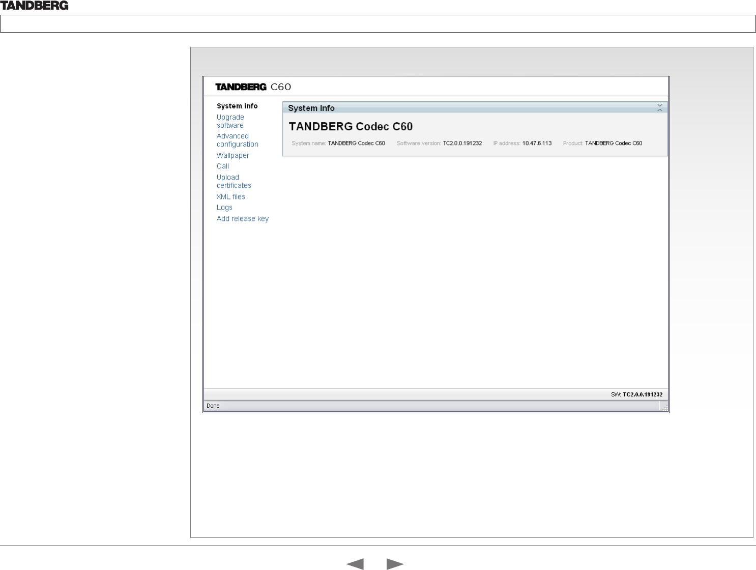
D14324.04—DECEMBER 2009 60
Profile series with Codec C60 Administrator Guide
Contents Introduction Getting started About the menus The settings menu Settings Library Cameras Appendices Contact us
The system info page
The web interface
The web interface allows for remote administration
of the system.
Open a web browser and enter the IP address of
the codec. From this page you have the following
menu options:
• System info
• Upgrade software
• Advanced configuration
• Wallpaper
• Call
• Upload certificates
• XML files
• Logs
• Add release key
Password protection of the web
interface
The web interface is password protected with the
same user name and password as defined for the
codec. See the Password protection section in the
Appendices for a detailed description.
NOTE! To activate the administrator password on
the web interface, after having defined or changed
the administrator password, a reboot of the codec
is required. Without a reboot the administrator
password will only apply when you login to the
codec.
Interactive menus
Click on the menu items
to access the pages. Each
web page is described in
the following pages.
Static information
Gives information about
system name, software
version, IP address and
product type.
Contents
Introduction
Getting started
About the menus
The Settings menu
The Settings library
Cameras
Appendices
Contact us
Appendices
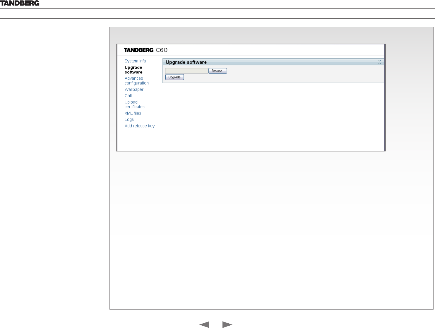
D14324.04—DECEMBER 2009 61
Profile series with Codec C60 Administrator Guide
Contents Introduction Getting started About the menus The settings menu Settings Library Cameras Appendices Contact us
The Upgrade software page
The web interface, cont...
The web interface allows for remote administration
of the system.
Open a web browser and enter the IP address of
the codec. From this page you have the following
menu options:
• System info
• Upgrade software
• Advanced configuration
• Wallpaper
• Call
• Upload certificates
• XML files
• Logs
• Add release key
How to upgrade the software on the codec:
1. Contact your TANDBERG representative to obtain the software
upgrade file.
2. Click Browse... and locate the upgrade file (.PKG)
3. Click the Upgrade button to start the installation.
4. Leave the system to allow the installation process to complete.
You can follow the progress on this page. When the upgrade
is successfully completed a message will appear. The upgrade
process takes a few minutes.
Contents
Introduction
Getting started
About the menus
The Settings menu
The Settings library
Cameras
Appendices
Contact us
Appendices
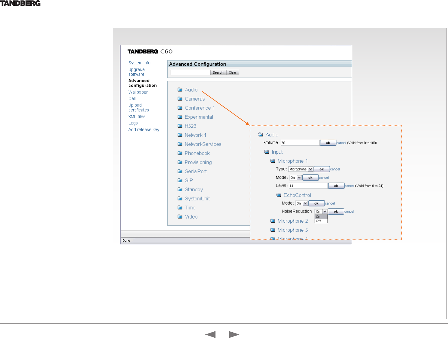
D14324.04—DECEMBER 2009 62
Profile series with Codec C60 Administrator Guide
Contents Introduction Getting started About the menus The settings menu Settings Library Cameras Appendices Contact us
The Advanced configuration page
The web interface, cont...
The web interface allows for remote administration
of the system.
Open a web browser and enter the IP address of
the codec. From this page you have the following
menu options:
• System info
• Upgrade software
• Advanced configuration
• Wallpaper
• Call
• Upload certificates
• XML files
• Logs
• Add release key
The Advanced configuration defines
the system settings and are structured
in a hierarchy, making up a database
of system settings.
Expanded view
Edit a value: To change a value, click
on the value to see the expanded view
as shown above.
Save: Click the OK button to save the
new value.
Cancel: When you want to leave
without saving, click Cancel.
Contents
Introduction
Getting started
About the menus
The Settings menu
The Settings library
Cameras
Appendices
Contact us
Appendices
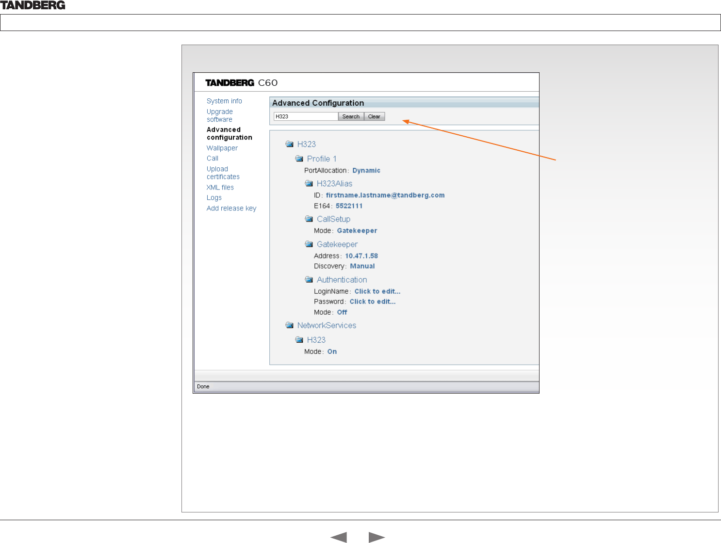
D14324.04—DECEMBER 2009 63
Profile series with Codec C60 Administrator Guide
Contents Introduction Getting started About the menus The settings menu Settings Library Cameras Appendices Contact us
The Advanced configuration, search functionality
The web interface, cont...
The web interface allows for remote administration
of the system.
Open a web browser and enter the IP address of
the codec. From this page you have the following
menu options:
• System info
• Upgrade software
• Advanced configuration
• Wallpaper
• Call
• Upload certificates
• XML files
• Logs
• Add release key
The search functionality
When searching for words like H323 or SIP, all
settings beginning with these words, included
all settings below in the hierarchy, will show in
the list.
Search: Enter as many characters as needed
to get the desired result and click the Search
button to initiate the search.
Clear: Click the Clear button to return to the
main view.
Contents
Introduction
Getting started
About the menus
The Settings menu
The Settings library
Cameras
Appendices
Contact us
Appendices
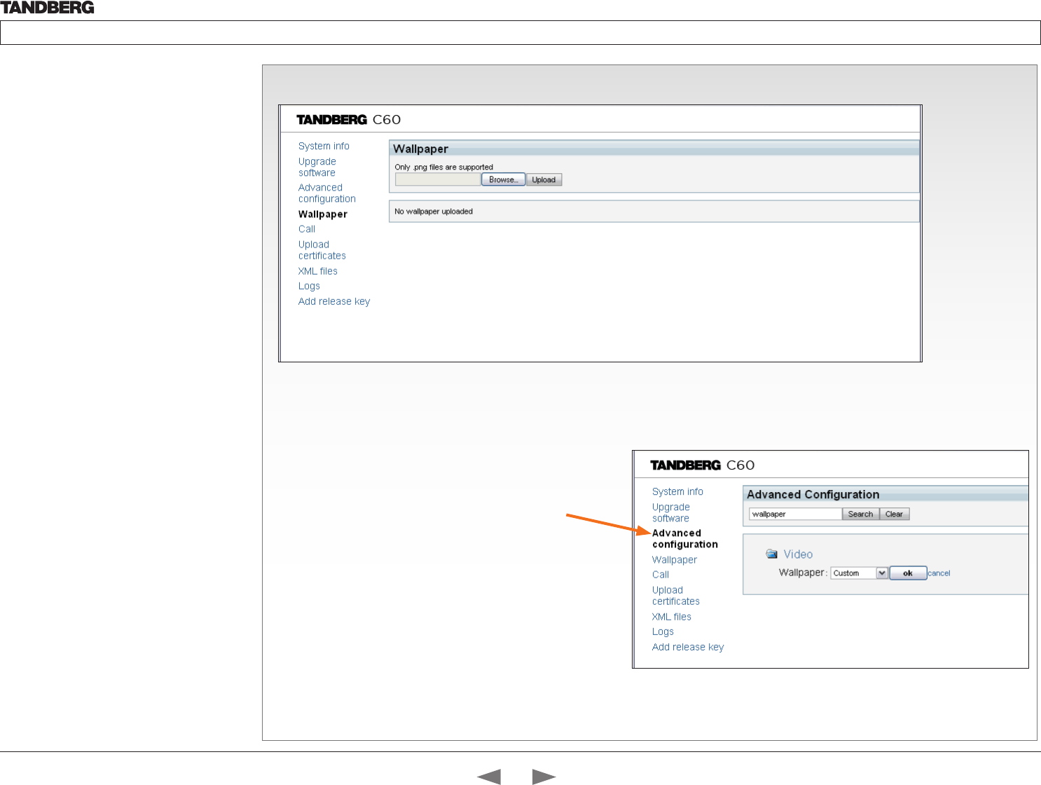
D14324.04—DECEMBER 2009 64
Profile series with Codec C60 Administrator Guide
Contents Introduction Getting started About the menus The settings menu Settings Library Cameras Appendices Contact us
The Wallpaper page
How to upload a custom wallpaper to the codec and configure the
codec to make use of it:
1. Click the Browse... button to locate the wallpaper file (.PNG)
2. Click the Upload button to upload the file to the codec and
refresh the web page to see the wallpaper you just uploaded.
3. Go to: Advanced configuration page and search for
Wallpaper. From the drop down list, select Custom. The new
wallpaper should now show on the monitor which is connected
to the codec.
If the new wallpaper does not show on the monitor connected to
the codec, you may have to toggle once between Wallpaper: None
and Custom to make the change take effect.
The web interface, cont...
The web interface allows for remote administration
of the system.
Open a web browser and enter the IP address of
the codec. From this page you have the following
menu options:
• System info
• Upgrade software
• Advanced configuration
• Wallpaper
• Call
• Upload certificates
• XML files
• Logs
• Add release key
Contents
Introduction
Getting started
About the menus
The Settings menu
The Settings library
Cameras
Appendices
Contact us
Appendices
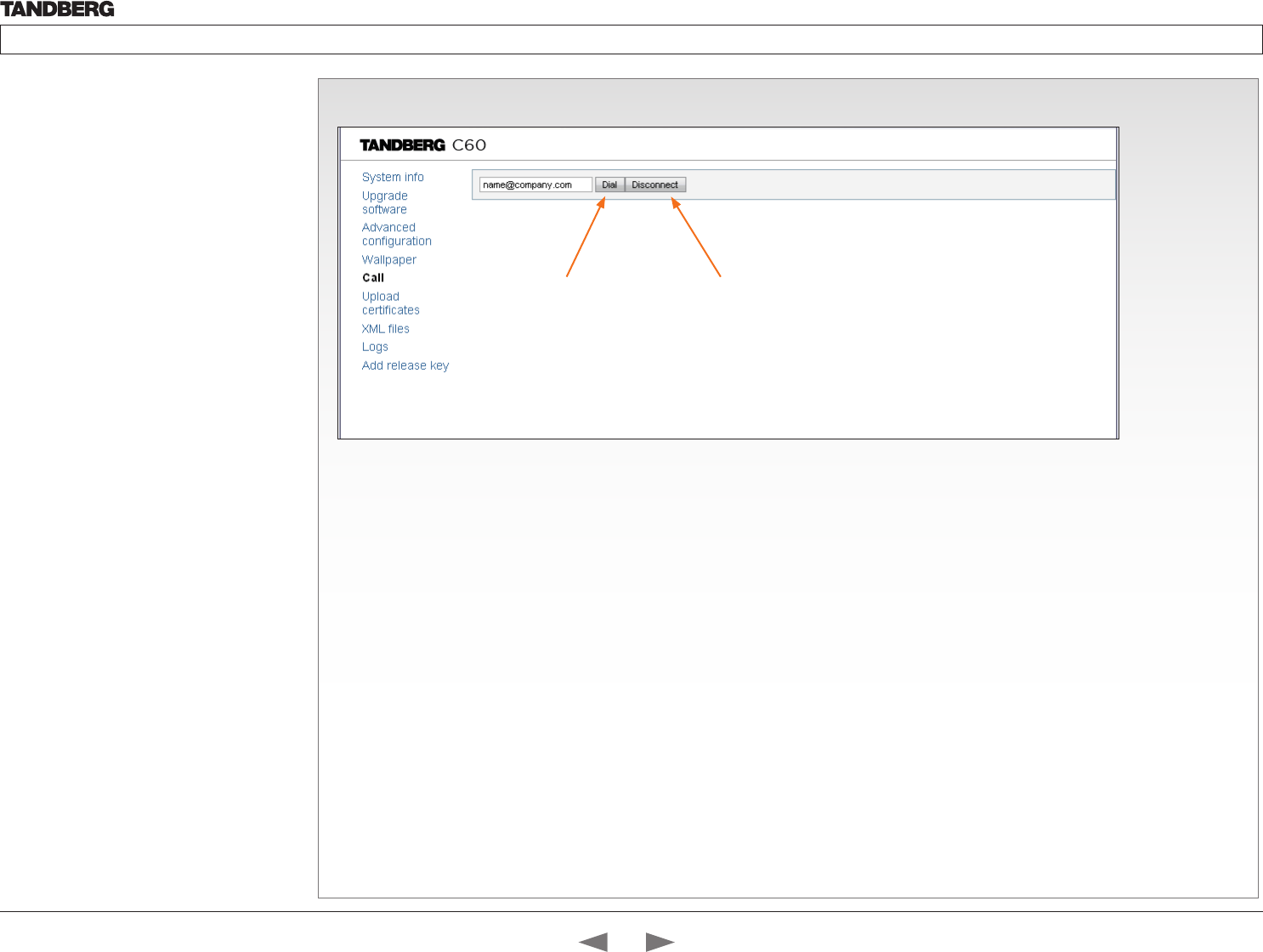
D14324.04—DECEMBER 2009 65
Profile series with Codec C60 Administrator Guide
Contents Introduction Getting started About the menus The settings menu Settings Library Cameras Appendices Contact us
The Call page
The web interface, cont...
The web interface allows for remote administration
of the system.
Open a web browser and enter the IP address of
the codec. From this page you have the following
menu options:
• System info
• Upgrade software
• Advanced configuration
• Wallpaper
• Call
• Upload certificates
• XML files
• Logs
• Add release key
Hang up
Press the Disconnect
button to end the call.
Dial
Enter the number or
address and press
the Dial button to dial.
NOTE! No status information is shown on the page during the call.
Contents
Introduction
Getting started
About the menus
The Settings menu
The Settings library
Cameras
Appendices
Contact us
Appendices
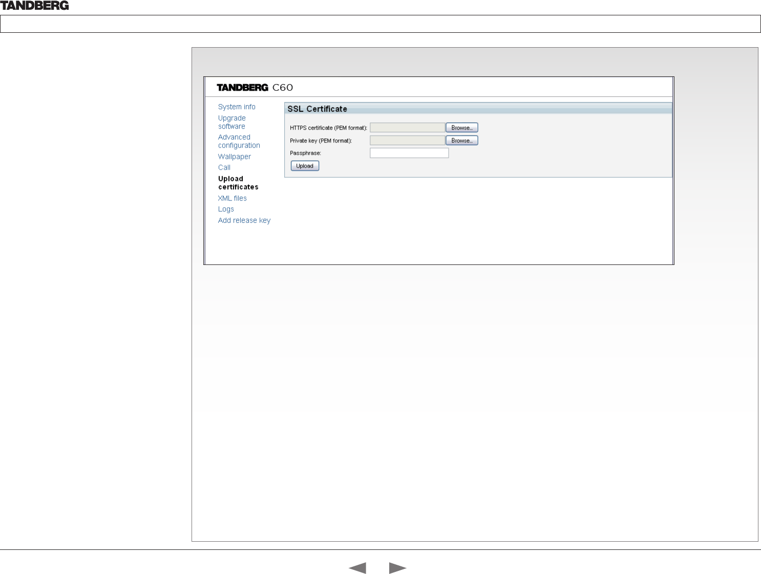
D14324.04—DECEMBER 2009 66
Profile series with Codec C60 Administrator Guide
Contents Introduction Getting started About the menus The settings menu Settings Library Cameras Appendices Contact us
The SSL Certificates page
About certificates
To install a certificate, you will need:
• HTTPS certificate ( .PEM format)
• ROOT certificate ( .PEM format)
• Private key ( .PEM format)
• Passphrase (optional)
How to upload the certificate
1. Contact your system administrator to obtain the required files (.PEM
format).
2. Click Browse... and locate the certificate files (.PEM)
3. Enter the Passphrase (optional).
4. Click the Upload button to install the certificates to the codec.
The web interface, cont...
The web interface allows for remote administration
of the system.
Open a web browser and enter the IP address of
the codec. From this page you have the following
menu options:
• System info
• Upgrade software
• Advanced configuration
• Wallpaper
• Call
• Upload certificates
• XML files
• Logs
• Add release key
Contents
Introduction
Getting started
About the menus
The Settings menu
The Settings library
Cameras
Appendices
Contact us
Appendices
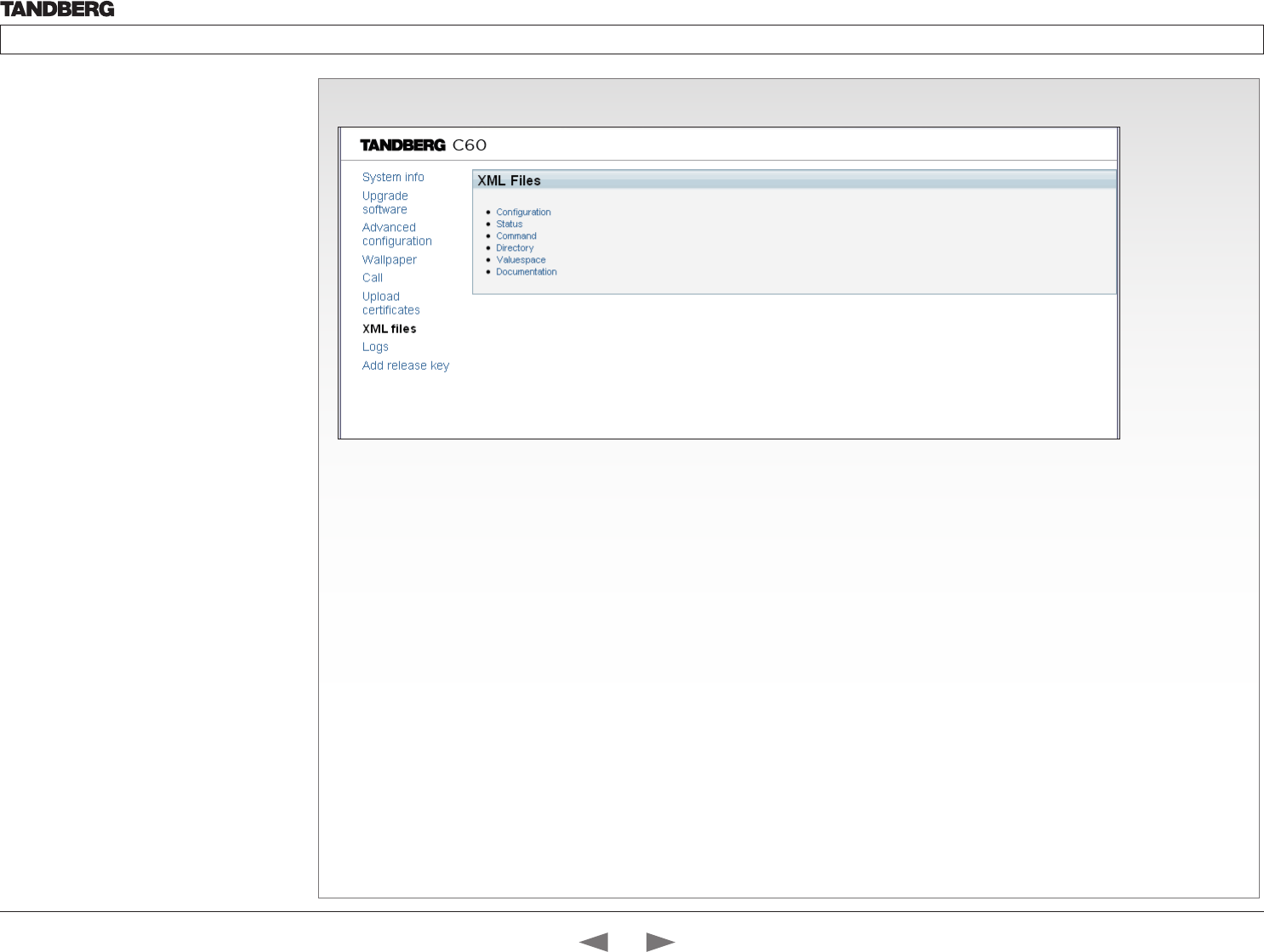
D14324.04—DECEMBER 2009 67
Profile series with Codec C60 Administrator Guide
Contents Introduction Getting started About the menus The settings menu Settings Library Cameras Appendices Contact us
The XML files page
Configuration
The Configuration file gives an overview of the system settings, which
are controlled from the Advanced configuration menu or from the API.
The configuration commands are structured in a hierarchy, making up a
database of system settings.
Status
The status information is structured in a hierarchy, making up a database
constantly being updated by the system to reflect system and process
changes.
Command
The Command file gives an overview of the commands available to instruct
the system to perform an action and are issued from the API. A Command
type command is usually followed by a set of parameters to specify how the
given action is to be executed.
Directory
The Directory file will be described later.
Valuespace
The Valuespace gives an overview of all the available value spaces.
Documentation
The Documentation file will be described later.
The web interface, cont...
The web interface allows for remote administration
of the system.
Open a web browser and enter the IP address of
the codec. From this page you have the following
menu options:
• System info
• Upgrade software
• Advanced configuration
• Wallpaper
• Call
• Upload certificates
• XML files
• Logs
• Add release key
Contents
Introduction
Getting started
About the menus
The Settings menu
The Settings library
Cameras
Appendices
Contact us
Appendices
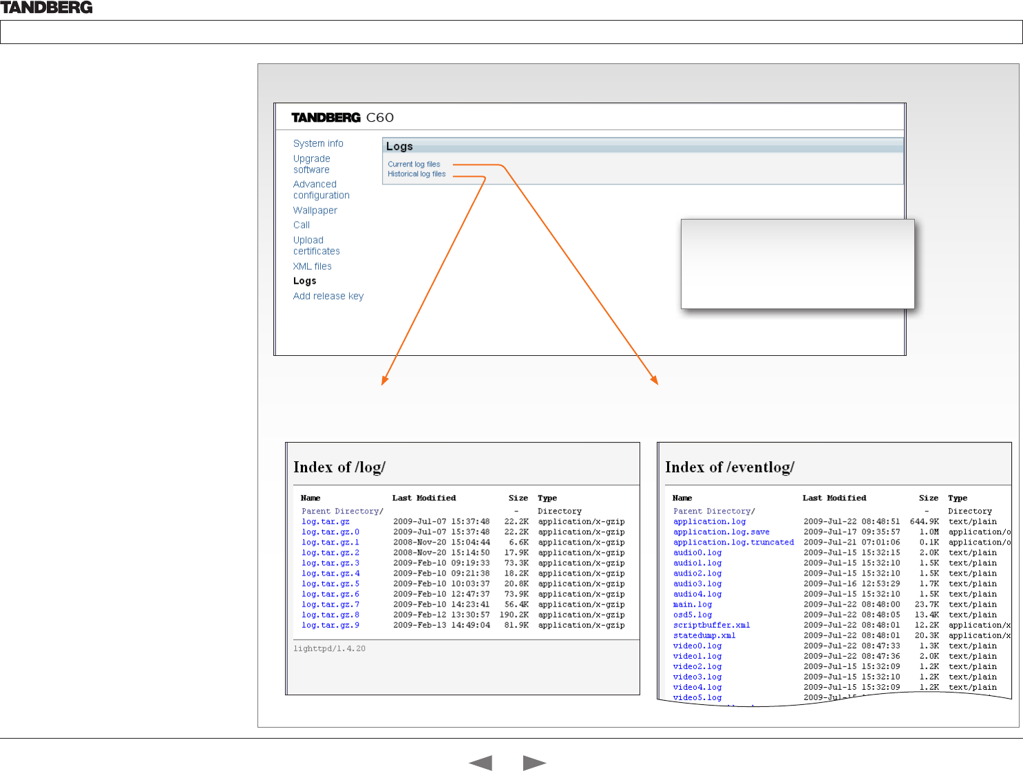
D14324.04—DECEMBER 2009 68
Profile series with Codec C60 Administrator Guide
Contents Introduction Getting started About the menus The settings menu Settings Library Cameras Appendices Contact us
The Logs page
The web interface, cont...
The web interface allows for remote administration
of the system.
Open a web browser and enter the IP address of
the codec. From this page you have the following
menu options:
• System info
• Upgrade software
• Advanced configuration
• Wallpaper
• Call
• Upload certificates
• XML files
• Logs
• Add release key
Historical log files
Time stamped historical log files. Click on a file and follow the
instructions in the dialog box to save the application file.
Current log files
Time stamped event log files. Click on a text file to view the file or follow
the instructions in the dialog box to save an application file.
The log files
The log files are TANDBERG specific debug
files which may be required by TANDBERG
in the need of technical support.
Contents
Introduction
Getting started
About the menus
The Settings menu
The Settings library
Cameras
Appendices
Contact us
Appendices
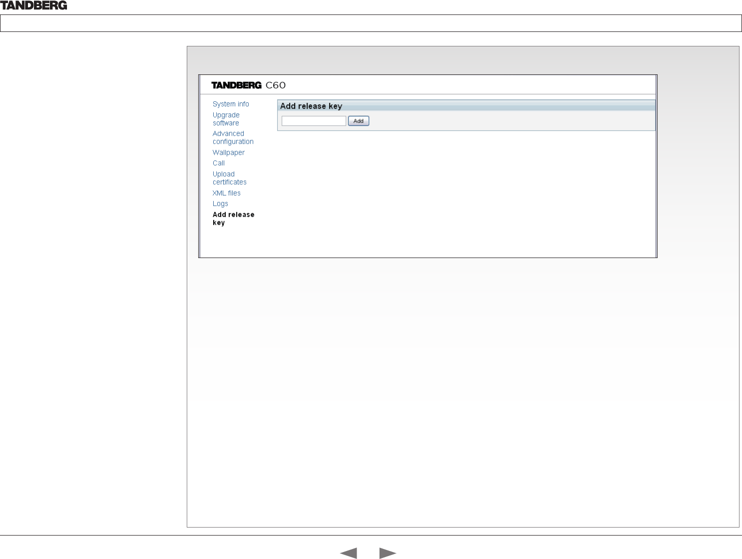
D14324.04—DECEMBER 2009 69
Profile series with Codec C60 Administrator Guide
Contents Introduction Getting started About the menus The settings menu Settings Library Cameras Appendices Contact us
The Add release key page
The web interface, cont...
The web interface allows for remote administration
of the system.
Open a web browser and enter the IP address of
the codec. From this page you have the following
menu options:
• System info
• Upgrade software
• Advanced configuration
• Wallpaper
• Call
• Upload certificates
• XML files
• Logs
• Add release key
Add
Enter the release key and
press the Add button.
The release key
Contact your TANDBERG representative to obtain the release key.
Contents
Introduction
Getting started
About the menus
The Settings menu
The Settings library
Cameras
Appendices
Contact us
Appendices
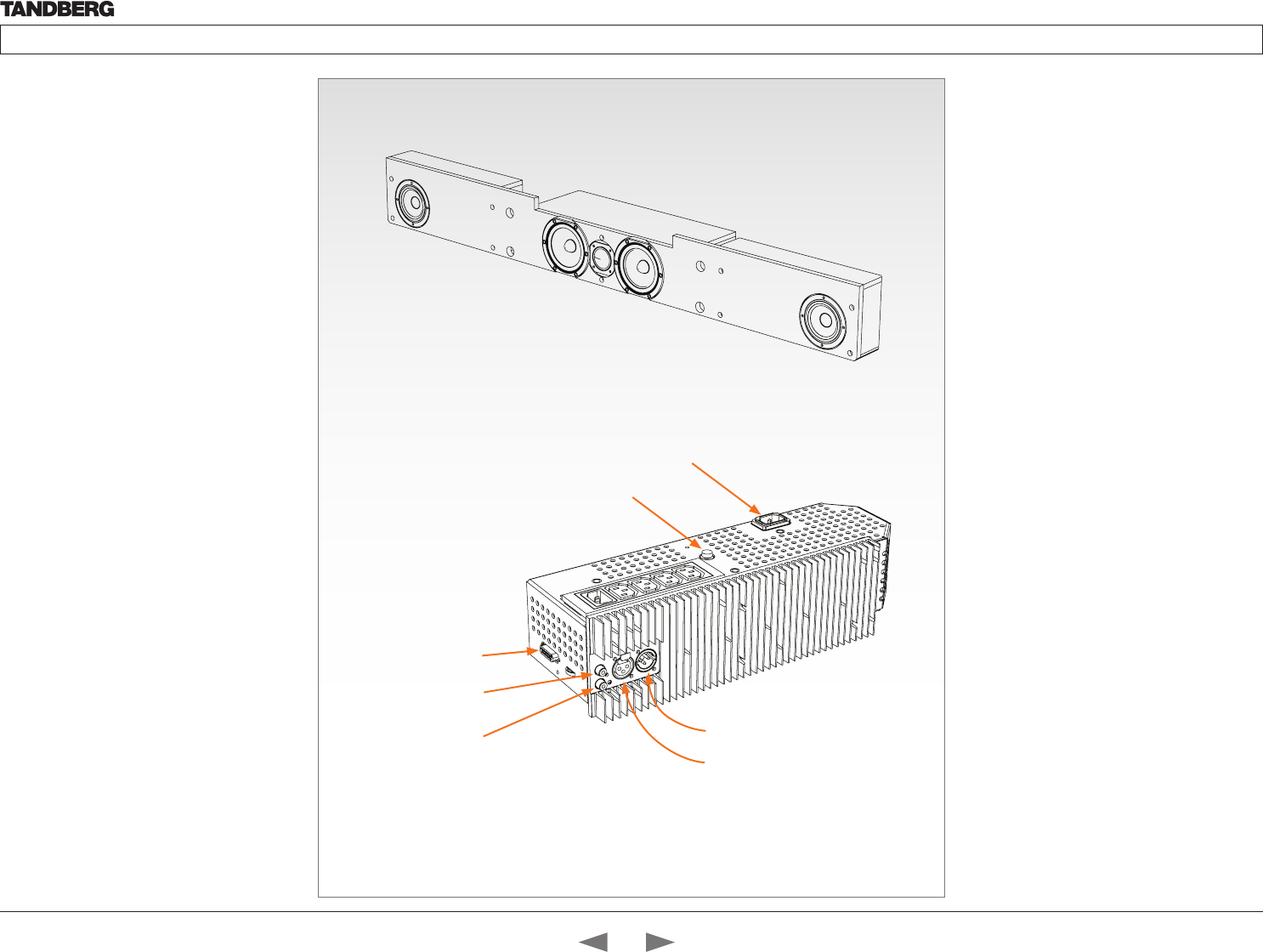
D14324.04—DECEMBER 2009 70
Profile series with Codec C60 Administrator Guide
Contents Introduction Getting started About the menus The settings menu Settings Library Cameras Appendices Contact us
The DNAM Amplifier
• 3 x 50W continuous average Center Output
Power (load specified by DNAM Center
Loudspeakers)
• 2 x 50W continuous average Stereo Output
Power (load specified by DNAM Stereo
Loudspeakers)
• Full dynamic range for audio (20Hz–20kHz)
• Digital Signal Processing and Filtering on all
channels for best audio detail clarity
• Digital Crossover Filtering on center channels
• In/out:
• Audio In - SPDIF (stereo) or Analog (mono),
using the same connector.
• Audio Differential In - (female XLR pinout: 1 -
GND, 2 – Signal (+), 3 – Signal (-))
• Audio Loop Out - line out directly from the
input, always analog even with SPDIF in.
• Audio Stereo Out - (male XLR, common
GND configuration)
• Fuse 2A 250V Slow, 5 x 20mm, Littelfuse
type 215002. Push and twist anti-clockvice to
release.
TANDBERG DNAM for
Profile 42”/52”
The TANDBERG DNAM – Digital Natural Audio
Module – is built on two specially designed
and separate modules, the amplifier and the
loudspeaker cabinet.
The DNAM Loudspeaker Cabinet
• 3-way Center Loudspeaker system
• Frequency range 50Hz - 20kHz
• 2 x 100 mm low- and midrange loudspeaker 8
Ohms nominal, excellent quality (SEAS Prestige
series)
• 1 x 25mm dome tweeter, 6 ohms nominal,
excellent quality
• Active crossover filtered audio signals received
from DNAM amplifier
• Long time max power 70 Watt on all
loudspeakers
• Enclosed MDF loudspeaker cabinet
Integrated Left / Right Stereo Loudspeaker
Stereo Loudspeaker System, each side has:
• 1 x 90 mm fullrange loudspeaker, 8 Ohms
nominal, excellent quality
• Frequency range 70 Hz - 20 kHz
• Enclosed MDF Loudspeaker cabinet
Power socket
DNAM Amplifier
DNAM Loudspeaker cabinet
Fuse
Audio Stereo Out (XLR)
Audio Differential In (XLR)
Multiaccess Audio
In / Out (D-SUB)
Audio In
(RCA)
Audio Loop Out
(RCA)
Contents
Introduction
Getting started
About the menus
The Settings menu
The Settings library
Cameras
Appendices
Contact us
Appendices
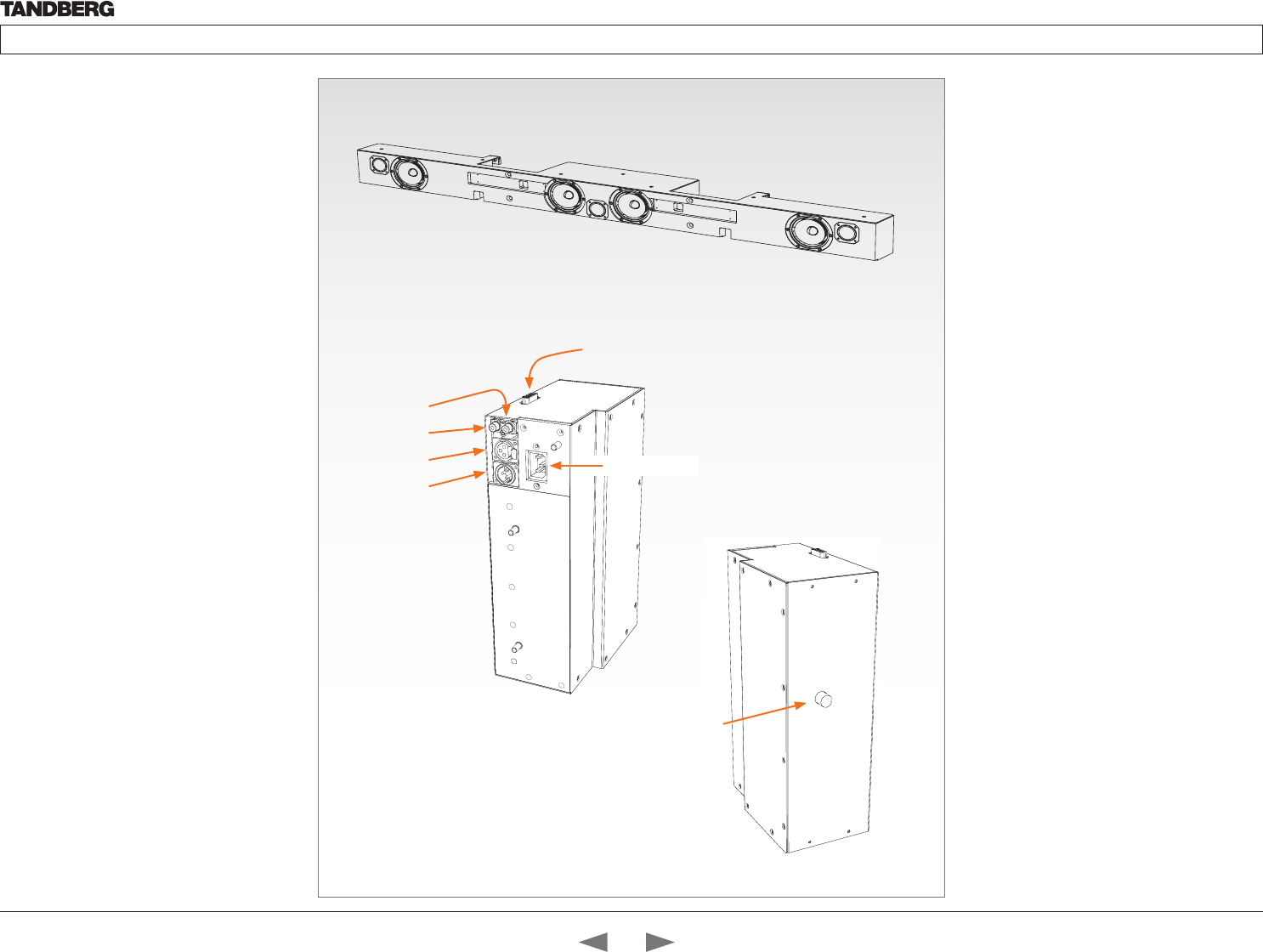
D14324.04—DECEMBER 2009 71
Profile series with Codec C60 Administrator Guide
Contents Introduction Getting started About the menus The settings menu Settings Library Cameras Appendices Contact us
TANDBERG DNAM for
Profile 65”
The TANDBERG DNAM – Digital Natural Audio
Module – is built on two specially designed
and separate modules, the amplifier and the
loudspeaker cabinet.
The DNAM Loudspeaker Cabinet
• 3-way Center Speaker system
• Frequency range 50Hz - 20kHz
• 2 x 100mm low- and midrange loudspeakers,
8 ohms nominal, excellent quality (SEAS Excel
series)
• 1 x 25mm dome tweeter, 6 ohms nominal, high
quality
• Crossover filtered audio signals received from
DNAM amplifier
• Long time max power 70 Watt on all
loudspeakers
• Enclosed MDF speaker cabinet
Integrated Stereo Speaker
2-way Stereo Speaker System, each side has:
• 1 x 100mm low- and midrange loudspeaker, 8
ohms nominal, excellent quality (SEAS Excel
series)
• 1 x 25mm dome tweeter, 6 ohms nominal, high
quality
• Passive crossover filter
• Frequency range 70 Hz - 20 kHz
• Long time max power 70 Watt
• Enclosed MDF speaker cabinet
RCA (audio in)
RCA (loop out)
XLR–female
XLR–male
15 pin D-SUB
(for loudspeakers)
Power socket
The DNAM Amplifier
• 3 x 50W continuous average Center Output
Power (load specified by DNAM Center
Speakers).
• 2 x 50W continuous average Stereo Output
Power (load specified by TANDBERG
Loudspeaker Stereo Kit).
• Full dynamic range for audio (high fidelity range)
or Integrated stereo speakers.
• Digital Signal Processing and Filtering on all
channels for best audio detail clarity.
• Digital Crossover Filtering on center channels.
• In/out:
• Audio In - SPDIF (stereo) or Analog (mono),
using the same connector.
• Differential In - (female XLR pinout: 1 - GND,
2 – Signal (+), 3 – Signal (-))
• Loop Out - line out directly from the input,
always analog even with SPDIF in.
• Stereo Out - (male XLR, common GND
configuration)
• Fuse 2A 250V Slow, 5 x 20mm, Littelfuse type
215002.
DNAM Amplifier
DNAM Loudspeaker
Fuses
Contents
Introduction
Getting started
About the menus
The Settings menu
The Settings library
Cameras
Appendices
Contact us
Appendices

D14324.04—DECEMBER 2009 72
Profile series with Codec C60 Administrator Guide
Contents Introduction Getting started About the menus The settings menu Settings Library Cameras Appendices Contact us
Supported RFCs in SIP
The RFC (Request for Comments) series contains technical and
organizational documents about the Internet, including the technical
specifications and policy documents produced by the Internet
Engineering Task Force (IETF).
Current RFCs and drafts supported in SIP
• RFC 1889 RTP: A Transport Protocol for Real-time Applications
• RFC 2190 RTP Payload Format for H.263 Video Streams
• RFC 2327 SDP: Session Description Protocol
• RFC 2396 Uniform Resource Identifiers (URI): Generic Syntax
• RFC 2429 RTP Payload Format for the 1998 Version of ITU-T Rec.
H.263 Video (H.263+)
• RFC 2617 Digest Authentication
• RFC 2782 DNS RR for specifying the location of services (DNS
SRV)
• RFC 2833 RTP Payload for DTMF Digits, Telephony Tones and
Telephony Signals
• RFC 2976 The SIP INFO Method
• RFC 3016 RTP Payload Format for MPEG-4 Audio/Visual Streams
• RFC 3047 RTP Payload Format for ITU-T Recommendation
G.722.1
• RFC 3261 SIP: Session Initiation Protocol
• RFC 3262 Reliability of Provisional Responses in SIP
• RFC 3263 Locating SIP Servers
• RFC 3264 An Offer/Answer Model with SDP
• RFC 3311 UPDATE method
• RFC 3361 DHCP Option for SIP Servers
• RFC 3420 Internet Media Type message/sipfrag
• RFC 3515 Refer method
• RFC 3550 RTP: A Transport Protocol for Real-Time Applications
• RFC 3581 Symmetric Response Routing
• RFC 3605 RTCP attribute in SDP
• RFC 3711 The Secure Real-time Transport Protocol (SRTP)
• RFC 3840 Indicating User Agent Capabilities in SIP
• RFC 3890 A Transport Independent Bandwidth Modifier for SDP
• RFC 3891 The SIP “Replaces” Header
• RFC 3892 Referred-By Mechanism
• RFC 3960 Early Media
• RFC 3984 RTP Payload Format for H.264 Video
• RFC 4028 Session Timers in SIP
• RFC 4145 TCP-Based Media Transport in the SDP
• RFC 4568 SDP:Security Descriptions for Media Streams
• RFC 4574 The Session Description Protocol (SDP) Label Attribute
• RFC 4582 The Binary Floor Control Protocol
• RFC 4585 Extended RTP Profile for RTCP-Based Feedback
• RFC 4587 RTP Payload Format for H.261 Video Streams
• RFC 4629 RTP Payload Format for ITU-T Rec. H.263 Video
• RFC 5168 XML Schema for Media Control
• RFC 4796 The SDP Content Attribute
• RFC 4583 SDP Format for BFCP Streams
• RFC 5589: SIP Call Control Transfer
• draft-ietf-avt-rtp-h264-rcdo-02
• draft-ietf-avt-rtp-rfc3984bis-06
• draft-ietf-sip-outbound-20: Managing Client Initiated Connections
Media capabilities supported in SIP
The audio and video media capabilities supported in SIP are the same
as for H.323.
Contents
Introduction
Getting started
About the menus
The Settings menu
The Settings library
Cameras
Appendices
Contact us
Appendices
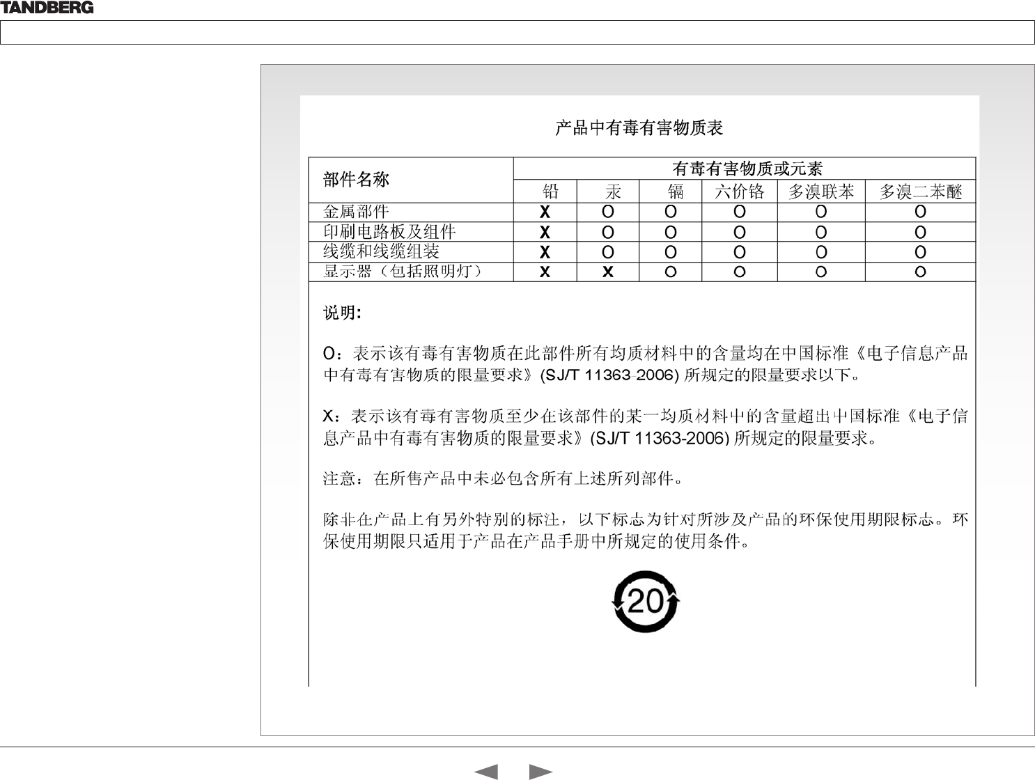
D14324.04—DECEMBER 2009 73
Profile series with Codec C60 Administrator Guide
Contents Introduction Getting started About the menus The settings menu Settings Library Cameras Appendices Contact us
China RoHS table
This product complies with the Chineese RoHS.
Contents
Introduction
Getting started
About the menus
The Settings menu
The Settings library
Cameras
Appendices
Contact us
Appendices
D14324.04—DECEMBER 2009 74
Profile series with Codec C60 Administrator Guide
Contents Introduction Getting started About the menus The settings menu Settings Library Cameras Appendices Contact us
CE Declaration for TANDBERG Profile
For an official, signed version of the document, or details regarding documentation from the technical
construction file, please contact TANDBERG.
EC Declaration of conformity
MANUFACTURER: TANDBERG Telecom AS TANDBERG Telecom AS TANDBERG Telecom AS TANDBERG Telecom AS
PRODUCT NAME: PROFILE 42 PROFILE 52 PROFILE 52 Dual TANDBERG Telepresence T1
TANDBERG Profile 65 Dual C90
PROFILE 65 w. C60
TYPE NUMBER: TTC60-12 TTC60-13 TTC60-14 TTC60-11
DESCRIPTION: Video Conferencing Equipment Video Conferencing Equipment Video Conferencing Equipment Video Conferencing Equipment
DIRECTIVES:
This equipment complies
with.
LVD 2006/95/EC
EMC 2004/108/EC
LVD 2006/95/EC
EMC 2004/108/EC
LVD 2006/95/EC
EMC 2004/108/EC
LVD 2006/95/EC
EMC 2004/108/EC
HARMONIZED
STANDARDS:
Applied in order to verify
compliance with directives.
EN 60950-1:2006
EN 55022 (2006)
EN 55024 (1998) + A1 (2001) + A2 (2003)
EN 61000-3-2 (2006)
EN 61000-3-3 (1995) + A1 (2001) + A2
(2005)
EN 60950-1:2006
EN 55022 (2006)
EN 55024 (1998) + A1 (2001) + A2 (2003)
EN 61000-3-2 (2006)
EN 61000-3-3 (1995) + A1 (2001) + A2
(2005)
EN 60950-1:2006
EN 55022 (2006)
EN 55024 (1998) + A1 (2001) + A2 (2003)
EN 61000-3-2 (2006)
EN 61000-3-3 (1995) + A1 (2001) + A2
(2005)
EN 60950-1:2006
EN 55022 (2006)
EN 55024 (1998) + A1 (2001) + A2 (2003)
EN 61000-3-2 (2006)
EN 61000-3-3 (1995) + A1 (2001) + A2 (2005)
TEST REPORTS and
CERTIFICATES ISSUED BY:
Report/Certificates No:
LVD (Nemko AS) 118330, 119330,
120725 and 123953
EMC (Nemko AS) E09640.00 (123774)
Report/Certificates No:
LVD (Nemko AS) 118330 and 119330
EMC (Nemko AS) E08604.00 (118330),
E09630.00 (119330)
R&TTE (Comlab) 03/559/3, 03/559/4,
03/560/3, 03/560/4
Report/Certificates No:
LVD (Nemko AS) 118330, 119330,
120725, 123953, 126466
EMC (Nemko AS) E09682.00 (128465),
E09634.00 (123042)
R&TTE (Comlab) 03/559/3, 03/559/4,
03/560/3, 03/560/4
Report/Certificates No:
LVD (Nemko AS) 121982,
LVD (Nemko AS) 136312 (Profile 65 w. C60 only)
EMC (Nemko AS) E08564.00,
EMC (Nemko AS) E08564.01 (Profile 65 w. C60
only)
TECHNICAL
CONSTRUCTION FILE NO.:
X14474 X14475 X14539 X14383 rev. 3
YEAR WHICH THE CE-
MARK WAS AFFIXED:
2009 2009 2009 2008
2009 (Profile 65 products)
Contents
Introduction
Getting started
About the menus
The Settings menu
The Settings library
Cameras
Appendices
Contact us
Appendices
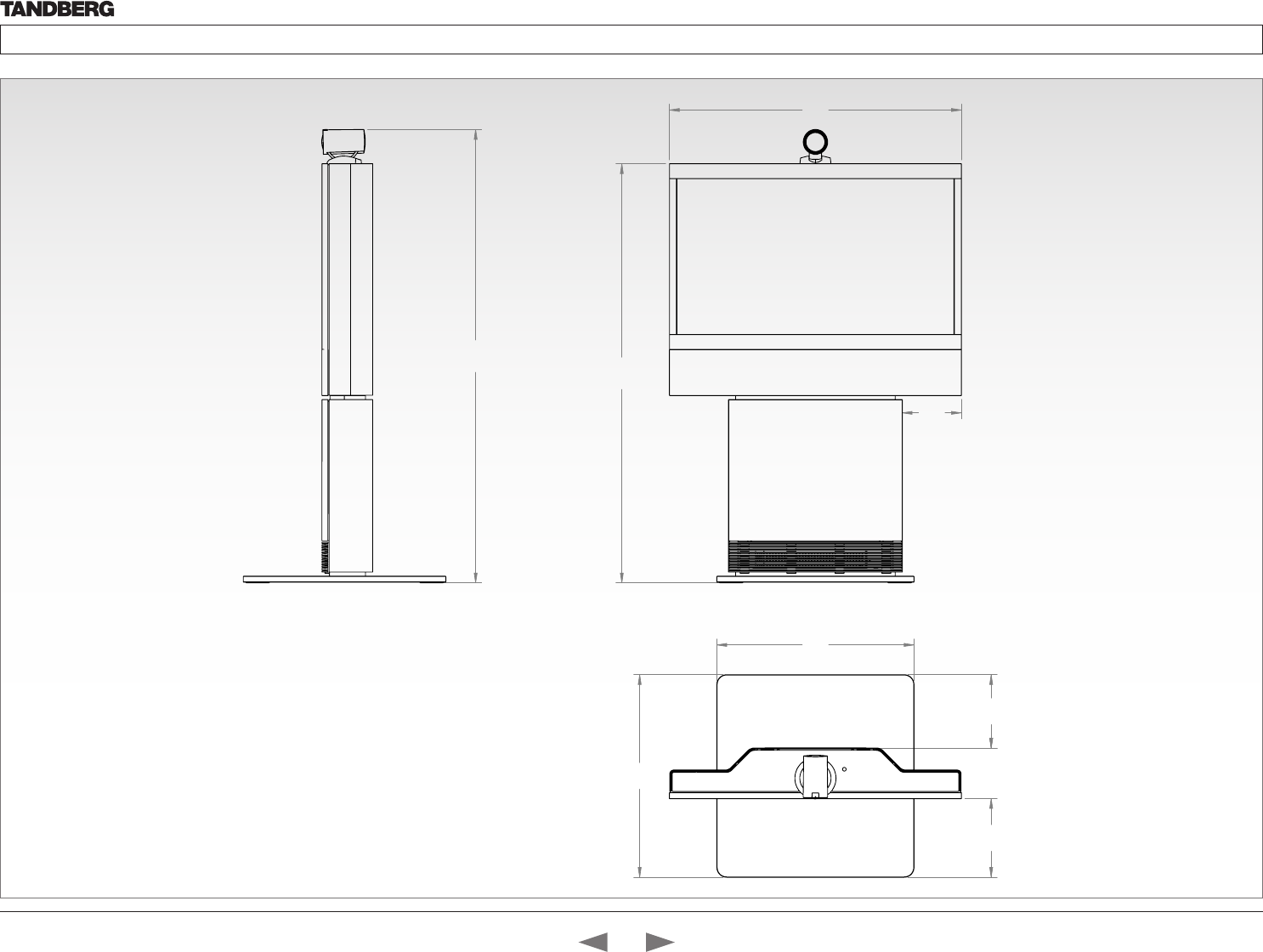
D14324.04—DECEMBER 2009 75
Profile series with Codec C60 Administrator Guide
Contents Introduction Getting started About the menus The settings menu Settings Library Cameras Appendices Contact us
Dimensions
Profile 42” with standalone foot
The dimensions in mm.
980
198
1407
1522
680
662
264 170 246
Contents
Introduction
Getting started
About the menus
The Settings menu
The Settings library
Cameras
Appendices
Contact us
Appendices
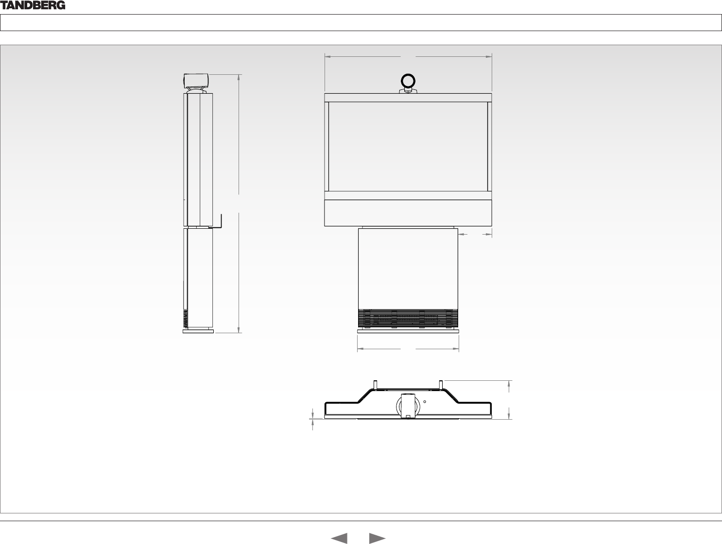
D14324.04—DECEMBER 2009 76
Profile series with Codec C60 Administrator Guide
Contents Introduction Getting started About the menus The settings menu Settings Library Cameras Appendices Contact us
Dimensions
Profile 42” with wall mount foot
The dimensions in mm.
198
980
594
1518
227
5
Contents
Introduction
Getting started
About the menus
The Settings menu
The Settings library
Cameras
Appendices
Contact us
Appendices
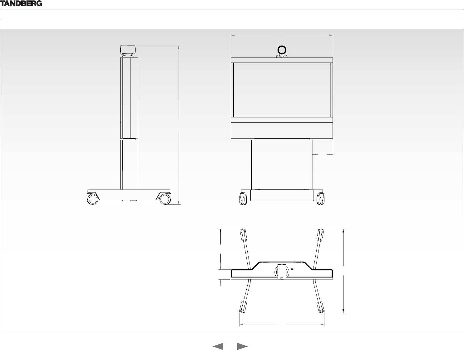
D14324.04—DECEMBER 2009 77
Profile series with Codec C60 Administrator Guide
Contents Introduction Getting started About the menus The settings menu Settings Library Cameras Appendices Contact us
980
198
1527,3
817
96
808
390
Dimensions
Profile 42” with wheelbase foot
The dimensions in mm.
Contents
Introduction
Getting started
About the menus
The Settings menu
The Settings library
Cameras
Appendices
Contact us
Appendices
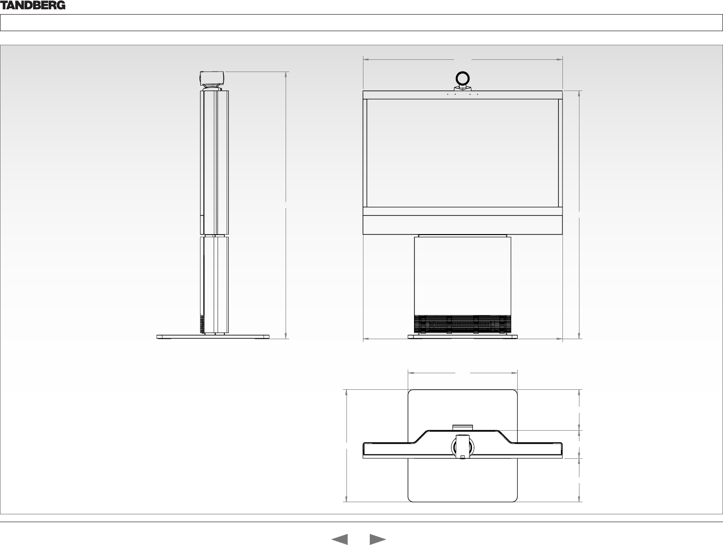
D14324.04—DECEMBER 2009 78
Profile series with Codec C60 Administrator Guide
Contents Introduction Getting started About the menus The settings menu Settings Library Cameras Appendices Contact us
Dimensions
Profile 52” with standalone foot
The dimensions in mm.
1205
1205,3
1498,3
660
680,0
264,2
170,0
245,8
1614,7
Profile 52" - scale 1:10
Contents
Introduction
Getting started
About the menus
The Settings menu
The Settings library
Cameras
Appendices
Contact us
Appendices
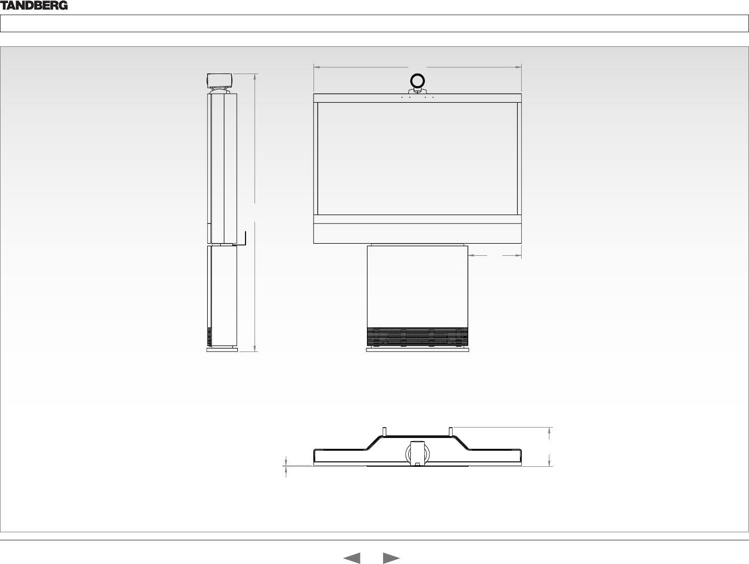
D14324.04—DECEMBER 2009 79
Profile series with Codec C60 Administrator Guide
Contents Introduction Getting started About the menus The settings menu Settings Library Cameras Appendices Contact us
Dimensions
Profile 52” with wall mount foot
The dimensions in mm.
310
1205
1612
227
5
Contents
Introduction
Getting started
About the menus
The Settings menu
The Settings library
Cameras
Appendices
Contact us
Appendices
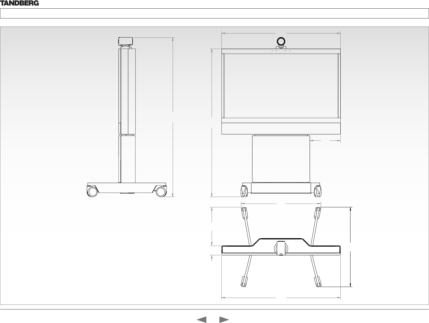
D14324.04—DECEMBER 2009 80
Profile series with Codec C60 Administrator Guide
Contents Introduction Getting started About the menus The settings menu Settings Library Cameras Appendices Contact us
Dimensions
Profile 52” with wheelbase foot
The dimensions in mm.
1205
1503
310
1617
1206
807
39096
808
Contents
Introduction
Getting started
About the menus
The Settings menu
The Settings library
Cameras
Appendices
Contact us
Appendices
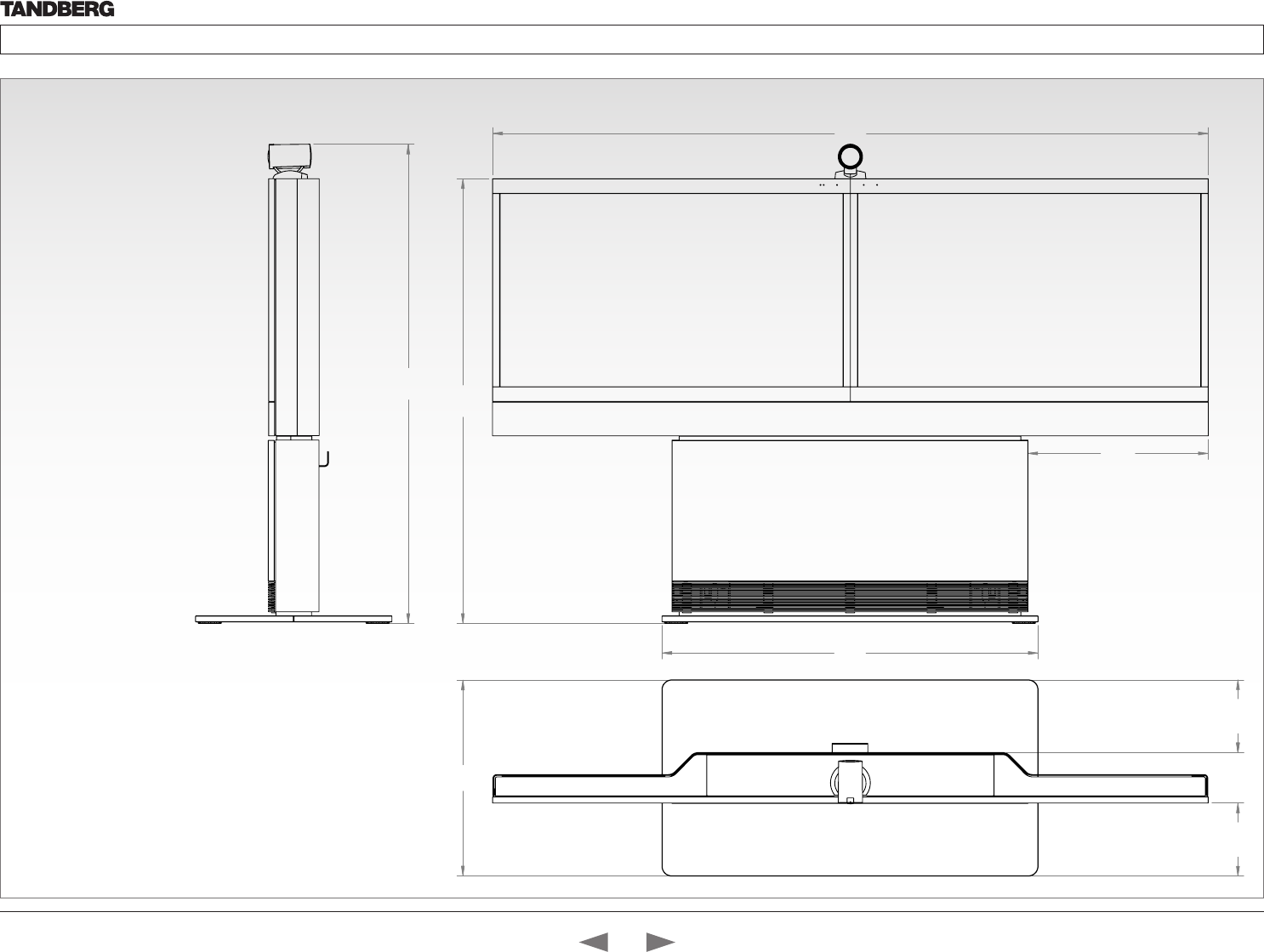
D14324.04—DECEMBER 2009 81
Profile series with Codec C60 Administrator Guide
Contents Introduction Getting started About the menus The settings menu Settings Library Cameras Appendices Contact us
Dimensions
Profile 52” Dual with standalone foot
The dimensions in mm.
2412
1268
607,9
1500
Profile 52" Dual - scale 1:10
660
246,6 170,1 245,3
1616
Contents
Introduction
Getting started
About the menus
The Settings menu
The Settings library
Cameras
Appendices
Contact us
Appendices
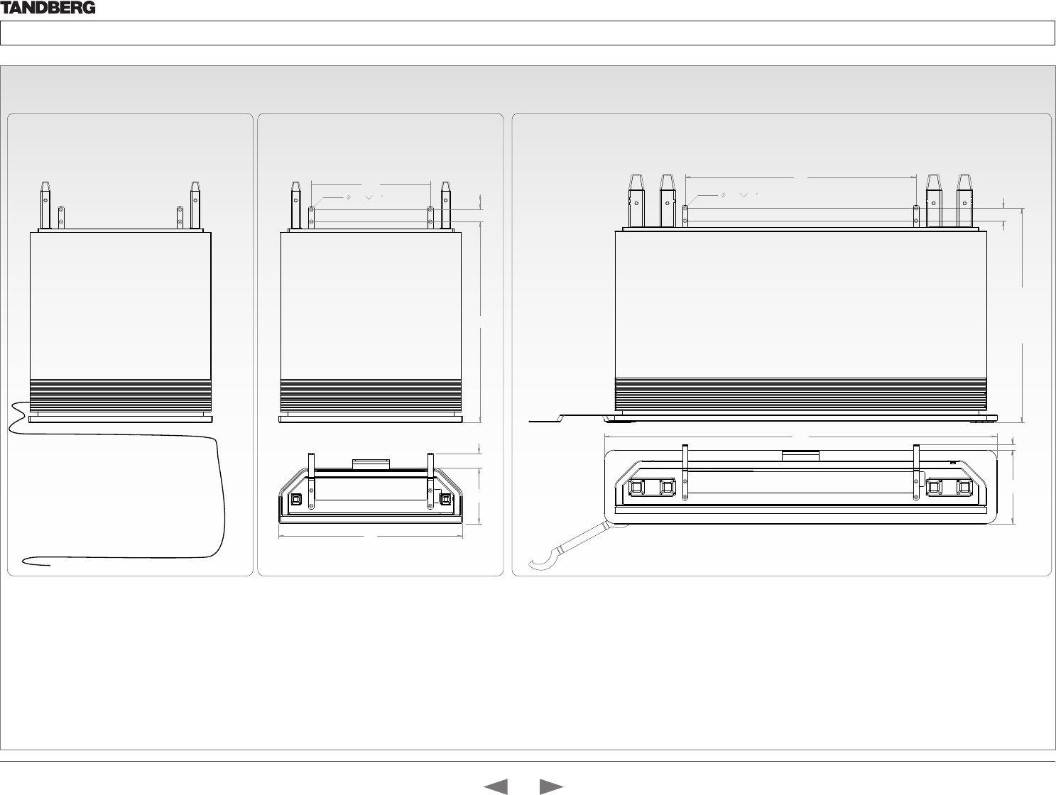
D14324.04—DECEMBER 2009 82
Profile series with Codec C60 Administrator Guide
Contents Introduction Getting started About the menus The settings menu Settings Library Cameras Appendices Contact us
Profile wall mount setup
Telecom AS
746
692
(adjustable feets)
40
1268
238 18
7,0 90
PROFILE 52 DUAL
384
7,0 90
594
180 47
686
40
PROFILE 42 AND 52
Cables are by de-
fault exiting the
system on right side,
but can easily be
swithced to left side.
PROFILE -WALL MOUNT SETUP
WARNING!
Due to the size and mass of this equipment, it is very important that
the wall mount unit is safely installed according to the installation
instructions and that the wall is able to safely support the product.
It is highly recommended that the wall mounted system is installed by
trained personnel
Mounting
Use the Allen key, which is found in the foot box, when fastening the
wall brackets to the bottom module with four M6x10 screws
Place the bottom module by the wall, mark where to bolt the bracket
and move away the bottom module
NOTE! Use a level to make sure the system is mounted in an upright
position. Add a spacer between the wall bracket and the wall if
necessary.
Add the suitable fixing device for the screws in the wall
Open the rear door and locate and connect the cables which are
lead out of the system at the rear side (the door is not accessible
when placed by the wall)
Place the bottom module by the wall and bolt it to the wall.
Contents
Introduction
Getting started
About the menus
The Settings menu
The Settings library
Cameras
Appendices
Contact us
Appendices
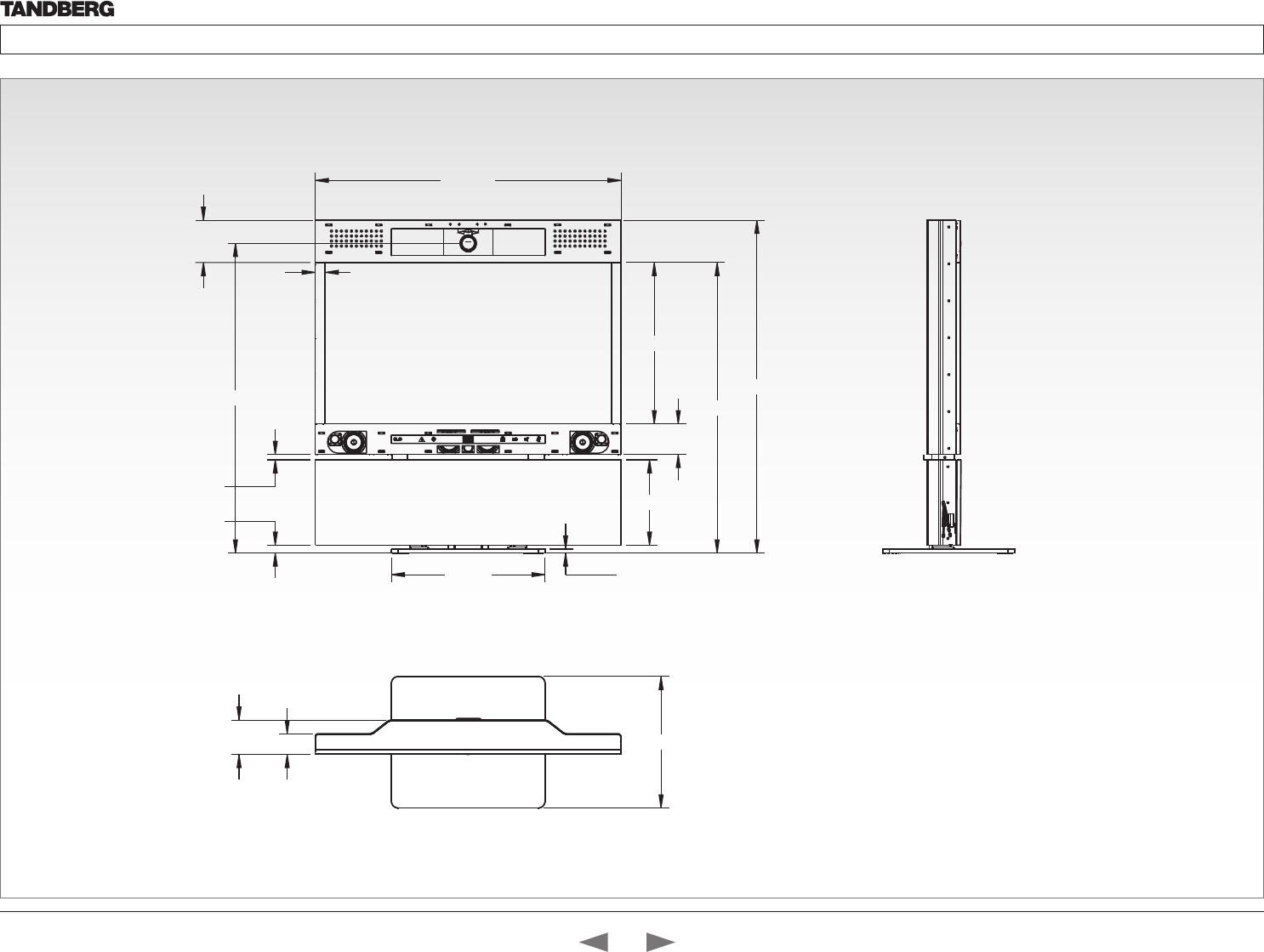
D14324.04—DECEMBER 2009 83
Profile series with Codec C60 Administrator Guide
Contents Introduction Getting started About the menus The settings menu Settings Library Cameras Appendices Contact us
Dimensions
Profile 65” with standalone foot
The dimensions in mm.
0,066
0,401
0,271
0,2351
8,94
7,112
8,2551
8,62
5,93
0,07 07 ,02
7,724
8,351
4,808
2,6541
0,8661
Contents
Introduction
Getting started
About the menus
The Settings menu
The Settings library
Cameras
Appendices
Contact us
Appendices
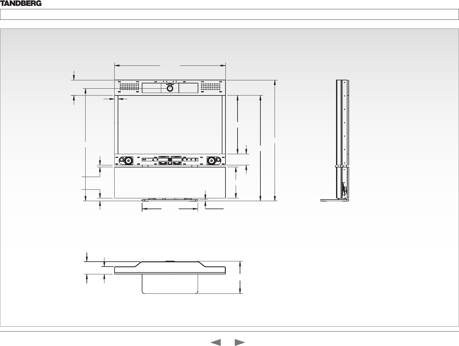
D14324.04—DECEMBER 2009 84
Profile series with Codec C60 Administrator Guide
Contents Introduction Getting started About the menus The settings menu Settings Library Cameras Appendices Contact us
Dimensions
Profile 65” with wall mounting foot
The dimensions in mm.
0
,
0,401
0,271
0,2351
8,94
7,112
8,2551
8,62
5,93
0,07 07 ,02
7,724
8,351
4,808
2,6541
0,8661
441
Contents
Introduction
Getting started
About the menus
The Settings menu
The Settings library
Cameras
Appendices
Contact us
Appendices
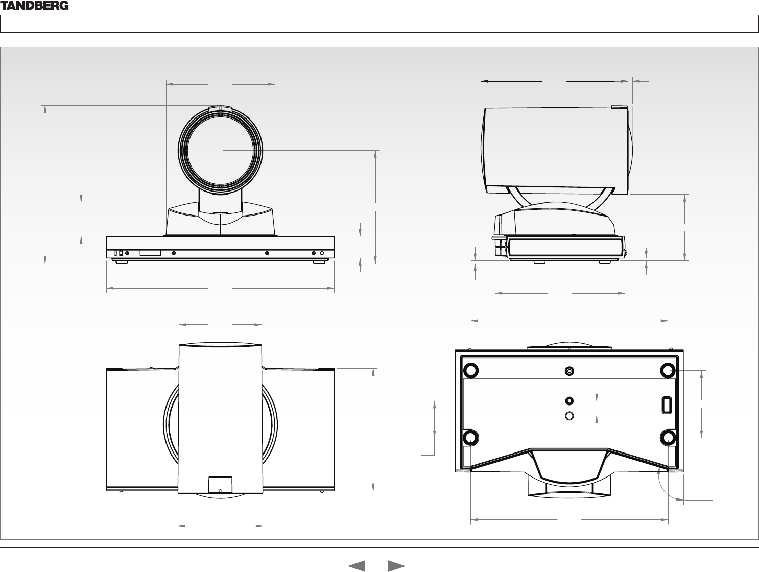
D14324.04—DECEMBER 2009 85
Profile series with Codec C60 Administrator Guide
Contents Introduction Getting started About the menus The settings menu Settings Library Cameras Appendices Contact us
220,0
105,0
20,5
105,9
(eye centre)
32,2
148,1
114,6
ø
82,0
ø
79,6
2,5
2,5
62,4
125,4
142,0 4,4
63,0
190,0
14,0
34,5
191,0
106,3°
Dimensions
PrecisionHD 1080p camera
The dimensions in mm.
Contents
Introduction
Getting started
About the menus
The Settings menu
The Settings library
Cameras
Appendices
Contact us
Appendices

D14324.04—DECEMBER 2009 86
Profile series with Codec C60 Administrator Guide
Contents Introduction Getting started About the menus The settings menu Settings Library Cameras Appendices Contact us
Technical specifications
for Profile 42”/52”
UNIT DELIVERED COMPLETE WITH:
Full HD LCD display, Codec C60, remote control,
PrecisionHD 1080p Camera, microphone (3x with single
screen, 4x with dual screen), Digital Audio Module,
integrated speakers and integrated cabling.
Choice of installation configuration: floor stand, wheel base
or wall mount on pedestal.
Choice of screen size and configuration.
MONITOR Available with:
• 52’’ Full HD LCD, 16:9, 1080x1920 resolution
• 42’’ Full HD LCD, 16:9, 1080x1920 resolution
BASE Available with:
• Floor standing foot plate
• Wheel base (not available on 52” dual)
• Wall mount on pedestal
BANDWIDTH
• H.323/SIP up to 6 Mbps point-to-point
• H.323/SIP up to 10 Mbps Multisite*
FIREWALL TRAVERSAL
• TANDBERG Expressway™ Technology
• H.460.18, H.460.19 Firewall Traversal
• SIP ICE
VIDEO STANDARDS
• H.261, H.263, H.263+, H.264
VIDEO FEATURES
• Native 16:9 Widescreen
• Advanced Screen Layouts
• Intelligent Video Management
• Local Auto Layout
VIDEO INPUTS (5 INPUTS)
2 X HDMI inputs, supported formats:
• 1920 x 1080@60, 59.94 Hz (1080p60)
• 1920 x 1080@50 Hz (1080p50)
• 1920 x 1080@30, 29.97 Hz (1080p30)
• 1920 x 1080@25 Hz (1080p25)
• 1920 x 1080@24, 23.97 Hz (1080p24)
• 1920 x 1200@50 Hz (WUXGA)
• 1680 x 1050@60 Hz (WSXGA+)
• 1600 x 1200@50, 60 Hz (UXGA)
• 1440 X 900@60 Hz (WXGA+)
• 1400 x 1050@60, 75 Hz
• 1366 x 768@60 Hz
• 1360 x 768@60 Hz
• 1280 x 1024@60, 75, 85 Hz (SXGA)
• 1280 x 960@60, 85 Hz
• 1280 x 800@60 Hz (WXGA)
• 1280 x 768@60, 75, 85 Hz (WXGA)
• 1280 x 720@60, 59.94 Hz (720p60)
• 1280 x 720@50 Hz (720p50)
• 1152 x 864@75 Hz
• 1024 x 768@60, 70, 75, 85 Hz (XGA)
• 848 x 480@60 Hz
• 800 x 600@56, 60, 72, 75, 85 Hz (SVGA)
• 720 x 576@50 Hz (576p50)
• 720 x 480@60, 59.94 Hz (480p60)
• 640 x 480@60, 72, 75, 85 Hz (VGA)
2 x DVI-I inputs, supported formats:
Digital (DVI-D):
• Same as HDMI, ref. above.
Analog RGB (DVI-A):
• 1920 x 1080@60 Hz (1080p60)
• 1920 x 1200@50 Hz (WUXGA)
• 1680 x 1050@60 Hz (WSXGA+)
• 1600 x 1200@60 Hz (UXGA)
• 1440 x 900@60 Hz (WXGA+)
• 1400 x 1050@60, 75 Hz
• 1366 x 768@60 Hz
• 1360 x 768@60 Hz
• 1280 x 1024@60, 75, 85 Hz (SXGA)
• 1280 x 960@60, 85 Hz
• 1280 x 800@60 Hz (WXGA)
• 1280 x 768@60, 75, 85 Hz (WXGA)
• 1280 x 720@60 Hz (720p60)
• 1152 x 864@75 Hz
• 1024 x 768@60, 70, 75, 85 Hz (XGA)
• 848 x 480@60 Hz
• 800 x 600@56, 60, 72, 75, 85 Hz (SVGA)
• 720 x 576@50 Hz
• 720 x 480@60, 59.94 Hz (480p60)
• 640 x 480@60, 72, 75, 85 Hz (VGA)
Analog YPbPr (DVI-A):
• 1920 x 1080@60 Hz (1080p60)
• 1920 x 1080@50 Hz (1080p50)
• 1920 x 1080@30 Hz (1080p30)
• 1920 x 1080@25 Hz (1080p25)
• 1280 x 720@60 Hz (720p60)
• 1280 x 720@50 Hz (720p50)
• 1280 x 720@30 Hz (720p30)
• 720 x 576@50 Hz (576p50)
• 720 x 480@60 Hz (480p60)
Extended Display Identification Data (EDID)
1 X Composite input (BNC connector), supported formats:
• PAL/NTSC
VIDEO OUTPUTS (2 OUTPUTS)
1 X HDMI output, 1 X DVI-I output, supported formats:
• 1920 x 1080@60 Hz (1080p60)
• 1920 x 1200@60Hz (WUXGA)
• 1600 x 1200@60 Hz (UXGA)
• 1366 x 768@60 Hz
• 1360 x 768@60 Hz
• 1280 x 720@60 Hz (720p60)
• 1280 x 1024@60 Hz (SXGA)
• 1280 x 768@60 Hz (WXGA)
• 1024 x 768@60 Hz (XGA)
• 800 x 600@60 Hz (SVGA)
• 640 x 480@60 Hz (VGA)
VESA Monitor Power Management
1 X Composite output (BNC connector), supported
formats:
• PAL/NTSC
LIVE VIDEO RESOLUTIONS (ENCODE/DECODE)
• 176 x 144@30 fps (QCIF)
• 352 x 288@30 fps (CIF)
• 512 x 288@30 fps (w288p)
• 576 x 448@30 fps (448p)
• 768 x 448@30 fps (w448p)
• 704 x 576@30 fps (4CIF)
• 1024 x 576@30 fps (w576p)
• 640 x 480@30 fps (VGA)
• 800 x 600@30 fps (SVGA)
• 1024 x 768@30 fps (XGA)
• 1280 x 1024@30 fps (SXGA)
• 1280 x 720@30 fps (720p30)
• 1920 x 1080@30 fps (1080p30)*
• 1280 x 768@30 fps (WXGA)
• 1440 x 900@30 fps (WXGA+)
• 1680 x 1050@30 fps (WSXGA+)
• 1600 x 1200@30 fps (UXGA)
• 512 x 288@60 fps (w288p60)*
• 768 x 448@60 fps (w448p60)*
• 1024 x 576@60 fps (w576p60)*
• 1280 x 720@60 fps (720p60)*
AUDIO STANDARDS
• G.711, G.722, G.722.1, 64 bit & 128 bit MPEG4 AAC-
LD, AAC-LD Stereo
AUDIO FEATURES
• CD-Quality 20KHz Mono and Stereo
• Four separate acoustic echo cancellers
• 4-port Audio mixer
• Automatic Gain Control (AGC)
• Automatic Noise Reduction
• Active lip synchronization
• ALD (Assistive Listening Devices) support with
acoustic echo cancellation
AUDIO INPUTS (7 INPUTS)
• 4 x microphone, 48V phantom powered, XLR
connector each with separate echo cancellers and
noise reduction,all microphones can be set for
balanced line level
• 2 x RCA/Phono, Line Level: Stereo PC input,
configurable to 2 x RCA/Phono, Line Level: Mono
auxiliary/DVD input
• 1 x HDMI, digital: Stereo PC/DVD inputs
AUDIO OUTPUTS (3 OUTPUTS)
• 2 x RCA/Phono, line level, stereo main audio,
configurable to S/PDIF or 2 x RCA/Phono, line level,
mono to recording device
• 1 x HDMI, digital, stereo main audio
DUAL STREAM
• H.239 (H.323) dual stream
• BFCP (SIP) dual stream
• Support for resolutions up to 1080p30 in both main
stream and dual stream simultaneously
MULTISITE FEATURES*
• 4-way 720p30 High Definition SIP/H.323 MultiSite
• Full individual audio and video transcoding
• Individual layouts in MultiSite CP (Takes out SelfView)
• H.323/SIP/VoIP in the same conference
• Best Impression (Automatic CP Layouts)
Contents
Introduction
Getting started
About the menus
The Settings menu
The Settings library
Cameras
Appendices
Contact us
Appendices

D14324.04—DECEMBER 2009 87
Profile series with Codec C60 Administrator Guide
Contents Introduction Getting started About the menus The settings menu Settings Library Cameras Appendices Contact us
POWER
Profile 42’’
• Auto-sensing power supply
• 100-120/200-240 VAC, 60/50Hz, 4.5A max
• Maximum power rating 365W
Profile 52’’
• Auto-sensing power supply
• 100-120/200-240 VAC, 60/50Hz, 6A max
• Maximum power rating 526W
Profile 52’’ Dual
• Auto-sensing power supply
• 100-120/200-240 VAC, 60/50Hz, 10/5A max
• Maximum power rating 870W
OPERATING TEMPERATURE AND HUMIDITY
• 0° C to 35° C (32° F to 95° F) ambient temperature
• 10% to 90% Relative Humidity (RH)
STORAGE AND TRANSPORT TEMPERATURE
• -20° C to 60° C (-4° F to 140° F) at RH 10–90% (non-
condensing)
APPROVALS
• Directive 2006/95/EC (Low Voltage Directive) –
Standard EN60950-1, 2nd ed
• Directive 2004/108/EC (EMC Directive) – Standard
EN55022, Class A – Standard EN55024 – Standard
EN61000-3-2/-3-3
• Approved according to UL60950-1 2nd ed and CAN/
CSA-C22.2 No. 60950-1-07, 2nd ed
• Complies with FCC15B Class A
DIMENSIONS
Profile 42’’
• Height: 63.78” / 162 cm
• Width: 38.58” / 98 cm
• Depth: 6.7” / 17 cm
Profile 52’’
• Height: 63.78” / 162 cm
• Width: 47.25” / 120 cm
• Depth: 6.7” / 17 cm
Profile 52’’ Dual
• Height: 63.5” / 161.3 cm
• Width: 95” / 241.2 cm
• Depth: 6.7” / 17 cm
WEIGHT
Profile 42’’
• With foot base: 220.5 lbs / 100 kg
• With wheel base: 200.6 lbs / 91 kg
Profile 52’’
• With foot base: 253.5 lbs / 115 kg
• With wheel base: 229.3 lbs / 104 kg
Profile 52’’ Dual
• With foot base: 515.9 lbs / 234 kg
All specifications are subject to change without notice,
system specifics may vary.
All images in these materials are for representational
purposes only, actual products may differ.
TANDBERG and Expressway are registered trademarks
or trademarks of TANDBERG in the U.S. and other
countries.
All other trademarks are property of their respective
owners.
MTBF PRODUCT RELIABILITY/MTBF
The predicted reliability is expressed in the expected
random Mean Time Between Failures (MTBF) for the
electronic components based on the Power On Hours:
Power On Hours (POH) > 69 000 hours
Useful Life Cycle > 6 years
ISO 9001 certificate is available upon request
December 2009
PRECISIONHD 1080P CAMERA
• 1/3” CMOS
• 12 x zoom
• +15°/-25° tilt, +/- 90° pan
• 43.5° vertical field of view
• 72° horizontal field of view
• Focus distance 0.3m–infinity
• 1920 x 1080 pixels progressive @ 60fps
• Other formats supported (configurable through Dip-
switch):
• 1920 x 1080@60 Hz (HDMI only)
• 1920 x 1080@50 Hz (HDMI only)
• 1920 x 1080@30 Hz
• 1920 x 1080@25 Hz
• 1280 x 720@60 Hz
• 1280 x 720@50 Hz
• 1280 x 720@30 Hz
• 1280 x 720@25 Hz
• Automatic or manual focus/brightness/white balance
• Far-end camera control
• Daisy-chain support (Visca protocol camera)
• Dual HDMI and HD-SDI output
• Upside-down mounting with automatic flipping of
picture
SYSTEM MANAGEMENT
• Support for the TANDBERG Management Suite
• Total management via embedded SNMP, Telnet, SSH,
XML, SOAP
• Remote software upload: via web server, SCP, HTTP,
HTTPS
• 1 x RS-232 for local control and diagnostics
• Remote control and on-screen menu system
DIRECTORY SERVICES
• Support for Local directories (My Contacts)
• Corporate Directory
• Unlimited entries using Server directory supporting
LDAP and H.350
• Unlimited number for Corporate directory (through
TMS)
• 200 number local directory
• Received Calls with Date and Time
• Placed Calls with Date and Time
• Missed Calls with Date and Time
• H.264, Encryption, Dual Stream from any site
• IP Downspeeding
• Dial in/Dial out
• Conference rates up to 10 Mbps
PROTOCOLS
• H.323
• SIP
EMBEDDED ENCRYPTION
• H.323/SIP point-to-point
• Standards-based: H.235 v2 & v3 and AES
• Automatic key generation and exchange
• Supported in Dual Stream
IP NETWORK FEATURES
• DNS lookup for service configuration
• Differentiated Services (QoS)
• IP adaptive bandwidth management (including flow
control)
• Auto gatekeeper discovery
• Dynamic playout and lip-sync buffering
• H.245 DTMF tones in H.323
• Date and Time support via NTP
• Packet Loss based Downspeeding
• URI Dialing
• TCP/IP
• DHCP
• Direct DNS dialing
SECURITY FEATURES
• Management via HTTPS and SSH
• IP Administration Password
• Menu Administration Password
• Disable IP services
• Network Settings protection
NETWORK INTERFACES **
• 1 x LAN/Ethernet (RJ-45) 10/100/1000 Mbit
OTHER INTERFACES
• USB host for future usage
• USB device for future usage
• GPIO for future usage
* requires option
** only one LAN/Ethernet interface supported
Technical specifications
for Profile 42”/52”, cont...
Contents
Introduction
Getting started
About the menus
The Settings menu
The Settings library
Cameras
Appendices
Contact us
Appendices

D14324.04—DECEMBER 2009 88
Profile series with Codec C60 Administrator Guide
Contents Introduction Getting started About the menus The settings menu Settings Library Cameras Appendices Contact us
Technical specifications
for Profile 65”
UNIT DELIVERED COMPLETE WITH:
Full HD LCD display, Codec C60, remote control,
PrecisionHD 1080p Camera, microphone, Digital Audio
Module, integrated speakers and integrated cabling.
MONITOR Available with:
• 65’’ Full HD LCD, 16:9, 1080x1920 resolution
BASE Available with:
• Floor standing foot plate
• Wall mount on pedestal
BANDWIDTH
• H.323/SIP up to 6 Mbps point-to-point
• H.323/SIP up to 10 Mbps Multisite*
FIREWALL TRAVERSAL
• TANDBERG Expressway™ Technology
• H.460.18, H.460.19 Firewall Traversal
• SIP ICE
VIDEO STANDARDS
• H.261, H.263, H.263+, H.264
VIDEO FEATURES
• Native 16:9 Wide screen
• Advanced Screen Layouts
• Intelligent Video Management
• Local Auto Layout
VIDEO INPUTS (5 INPUTS)
2 X HDMI inputs, supported formats:
• 1920 x 1080@60, 59.94 Hz (1080p60)
• 1920 x 1080@50 Hz (1080p50)
• 1920 x 1080@30, 29.97 Hz (1080p30)
• 1920 x 1080@25 Hz (1080p25)
• 1920 x 1080@24, 23.97 Hz (1080p24)
• 1920 x 1200@50 Hz (WUXGA)
• 1680 x 1050@60 Hz (WSXGA+)
• 1600 x 1200@50, 60 Hz (UXGA)
• 1440 X 900@60 Hz (WXGA+)
• 1400 x 1050@60, 75 Hz
• 1366 x 768@60 Hz
• 1360 x 768@60 Hz
• 1280 x 1024@60, 75, 85 Hz (SXGA)
• 1280 x 960@60, 85 Hz
• 1280 x 800@60 Hz (WXGA)
• 1280 x 768@60, 75, 85 Hz (WXGA)
• 1280 x 720@60, 59.94 Hz (720p60)
• 1280 x 720@50 Hz (720p50)
• 1152 x 864@75 Hz
• 1024 x 768@60, 70, 75, 85 Hz (XGA)
• 848 x 480@60 Hz
• 800 x 600@56, 60, 72, 75, 85 Hz (SVGA)
• 720 x 576@50 Hz (576p50)
• 720 x 480@60, 59.94 Hz (480p60)
• 640 x 480@60, 72, 75, 85 Hz (VGA)
2 x DVI-I inputs, supported formats:
Digital (DVI-D):
• Same as HDMI, ref. above.
Analog RGB (DVI-A):
• 1920 x 1080@60 Hz (1080p60)
• 1920 x 1200@50 Hz (WUXGA)
• 1680 x 1050@60 Hz (WSXGA+)
• 1600 x 1200@60 Hz (UXGA)
• 1440 x 900@60 Hz (WXGA+)
• 1400 x 1050@60, 75 Hz
• 1366 x 768@60 Hz
• 1360 x 768@60 Hz
• 1280 x 1024@60, 75, 85 Hz (SXGA)
• 1280 x 960@60, 85 Hz
• 1280 x 800@60 Hz (WXGA)
• 1280 x 768@60, 75, 85 Hz (WXGA)
• 1280 x 720@60 Hz (720p60)
• 1152 x 864@75 Hz
• 1024 x 768@60, 70, 75, 85 Hz (XGA)
• 848 x 480@60 Hz
• 800 x 600@56, 60, 72, 75, 85 Hz (SVGA)
• 720 x 576@50 Hz
• 720 x 480@60, 59.94 Hz (480p60)
• 640 x 480@60, 72, 75, 85 Hz (VGA)
Analog YPbPr (DVI-A):
• 1920 x 1080@60 Hz (1080p60)
• 1920 x 1080@50 Hz (1080p50)
• 1920 x 1080@30 Hz (1080p30)
• 1920 x 1080@25 Hz (1080p25)
• 1280 x 720@60 Hz (720p60)
• 1280 x 720@50 Hz (720p50)
• 1280 x 720@30 Hz (720p30)
• 720 x 576@50 Hz (576p50)
• 720 x 480@60 Hz (480p60)
Extended Display Identification Data (EDID)
1 X Composite input (BNC connector), supported formats:
• PAL/NTSC
VIDEO OUTPUTS (2 OUTPUTS)
1 X HDMI output, 1 X DVI-I output, supported formats:
• 1920 x 1080@60 Hz (1080p60)
• 1920 x 1200@60Hz (WUXGA)
• 1600 x 1200@60 Hz (UXGA)
• 1366 x 768@60 Hz
• 1360 x 768@60 Hz
• 1280 x 720@60 Hz (720p60)
• 1280 x 1024@60 Hz (SXGA)
• 1280 x 768@60 Hz (WXGA)
• 1024 x 768@60 Hz (XGA)
• 800 x 600@60 Hz (SVGA)
• 640 x 480@60 Hz (VGA)
VESA Monitor Power Management
1 X Composite output (BNC connector), supported
formats:
• PAL/NTSC
LIVE VIDEO RESOLUTIONS (ENCODE/DECODE)
• 176 x 144@30 fps (QCIF)
• 352 x 288@30 fps (CIF)
• 512 x 288@30 fps (w288p)
• 576 x 448@30 fps (448p)
• 768 x 448@30 fps (w448p)
• 704 x 576@30 fps (4CIF)
• 1024 x 576@30 fps (w576p)
• 640 x 480@30 fps (VGA)
• 800 x 600@30 fps (SVGA)
• 1024 x 768@30 fps (XGA)
• 1280 x 1024@30 fps (SXGA)
• 1280 x 720@30 fps (720p30)
• 1920 x 1080@30 fps (1080p30)*
• 1280 x 768@30 fps (WXGA)
• 1440 x 900@30 fps (WXGA+)
• 1680 x 1050@30 fps (WSXGA+)
• 1600 x 1200@30 fps (UXGA)
• 512 x 288@60 fps (w288p60)*
• 768 x 448@60 fps (w448p60)*
• 1024 x 576@60 fps (w576p60)*
• 1280 x 720@60 fps (720p60)*
AUDIO STANDARDS
• G.711, G.722, G.722.1, 64 bit & 128 bit MPEG4 AAC-
LD, AAC-LD Stereo
AUDIO FEATURES
• CD-Quality 20KHz Mono and Stereo
• Four separate acoustic echo cancellers
• 4-port Audio mixer
• Automatic Gain Control (AGC)
• Automatic Noise Reduction
• Active lip synchronization
• ALD (Assistive Listening Devices) support with
acoustic echo cancellation
AUDIO INPUTS (7 INPUTS)
• 4 x microphone, 48V phantom powered, XLR
connector each with separate echo cancellers and
noise reduction,all microphones can be set for
balanced line level
• 2 x RCA/Phono, Line Level: Stereo PC input,
configurable to 2 x RCA/Phono, Line Level: Mono
auxiliary/DVD input
• 1 x HDMI, digital: Stereo PC/DVD inputs
AUDIO OUTPUTS (3 OUTPUTS)
• 2 x RCA/Phono, line level, stereo main audio,
configurable to S/PDIF or 2 x RCA/Phono, line level,
mono to recording device
• 1 x HDMI, digital, stereo main audio
DUAL STREAM
• H.239 (H.323) dual stream
• BFCP (SIP) dual stream
• Support for resolutions up to 1080p30 in both main
stream and dual stream simultaneously
MULTISITE FEATURES*
• 4-way 720p30 High Definition SIP/H.323 MultiSite
• Full individual audio and video transcoding
• Individual layouts in MultiSite CP (Takes out SelfView)
• H.323/SIP/VoIP in the same conference
• Best Impression (Automatic CP Layouts)
• H.264, Encryption, Dual Stream from any site
• IP Downspeeding
• Dial in/Dial out
• Conference rates up to 10 Mbps
Contents
Introduction
Getting started
About the menus
The Settings menu
The Settings library
Cameras
Appendices
Contact us
Appendices

D14324.04—DECEMBER 2009 89
Profile series with Codec C60 Administrator Guide
Contents Introduction Getting started About the menus The settings menu Settings Library Cameras Appendices Contact us
OPERATING TEMPERATURE AND HUMIDITY
• 0° C to 35° C (32° F to 95° F) ambient temperature
• 10% to 90% Relative Humidity (RH)
STORAGE AND TRANSPORT TEMPERATURE
• -20° C to 60° C (-4° F to 140° F) at RH 10–90% (non-
condensing)
APPROVALS
• • Directive 2006/95/EC (Low Voltage Directive)
• • — Standard EN 60950-1
• • Directive 2004/108/EC (EMC Directive)
• • — Standard EN 55022, Class B
• • — Standard EN 55024
• • — Standard EN 61000-3-2/-3-3
• • Approved according to UL 60950-1 and CSA 60950-
• 1-07
• • Complies with FCC15B Class B
DIMENSIONS
• • Height: 167 cm (65.6 inches)
• • Width: 153 cm (60.3 inches)
• • Depth: 17 cm (6.8 inches)
WEIGHT
• With foot base: 330 lbs / 150 kg
All specifications are subject to change without notice,
system specifics may vary.
All images in these materials are for representational
purposes only, actual products may differ.
TANDBERG and Expressway are registered trademarks
or trademarks of TANDBERG in the U.S. and other
countries.
All other trademarks are property of their respective
owners.
MTBF PRODUCT RELIABILITY/MTBF
The predicted reliability is expressed in the expected
random Mean Time Between Failures (MTBF) for the
electronic components based on the Power On Hours:
Power On Hours (POH) > 69 000 hours
Useful Life Cycle > 6 years
ISO 9001 certificate is available upon request
December 2009
• 43.5° vertical field of view
• 72° horizontal field of view
• Focus distance 0.3m–infinity
• 1920 x 1080 pixels progressive @ 60fps
• Other formats supported (configurable through Dip-
switch):
• 1920 x 1080@60 Hz (HDMI only)
• 1920 x 1080@50 Hz (HDMI only)
• 1920 x 1080@30 Hz
• 1920 x 1080@25 Hz
• 1280 x 720@60 Hz
• 1280 x 720@50 Hz
• 1280 x 720@30 Hz
• 1280 x 720@25 Hz
• Automatic or manual focus/brightness/white balance
• Far-end camera control
• Daisy-chain support (Visca protocol camera)
• Dual HDMI and HD-SDI output
• Upside-down mounting with automatic flipping of
picture
SYSTEM MANAGEMENT
• Support for the TANDBERG Management Suite
• Total management via embedded SNMP, Telnet, SSH,
XML, SOAP
• Remote software upload: via web server, SCP, HTTP,
HTTPS
• 1 x RS-232 for local control and diagnostics
• Remote control and on-screen menu system
DIRECTORY SERVICES
• Support for Local directories (My Contacts)
• Corporate Directory
• Unlimited entries using Server directory supporting
LDAP and H.350
• Unlimited number for Corporate directory (through
TMS)
• 200 number local directory
• Received Calls with Date and Time
• Placed Calls with Date and Time
• Missed Calls with Date and Time
POWER
• Auto-sensing power supply
• 100-120/200-240 VAC, 60/50Hz
• Maximum power rating 800 Watt
• Normal operation 650 Watt
PROTOCOLS
• H.323
• SIP
EMBEDDED ENCRYPTION
• H.323/SIP point-to-point
• Standards-based: H.235 v2 & v3 and AES
• Automatic key generation and exchange
• Supported in Dual Stream
IP NETWORK FEATURES
• DNS lookup for service configuration
• Differentiated Services (QoS)
• IP adaptive bandwidth management (including flow
control)
• Auto gatekeeper discovery
• Dynamic playout and lip-sync buffering
• H.245 DTMF tones in H.323
• Date and Time support via NTP
• Packet Loss based Downspeeding
• URI Dialing
• TCP/IP
• DHCP
• Direct DNS dialing
SECURITY FEATURES
• Management via HTTPS and SSH
• IP Administration Password
• Menu Administration Password
• Disable IP services
• Network Settings protection
NETWORK INTERFACES **
• 1 x LAN/Ethernet (RJ-45) 10/100/1000 Mbit
OTHER INTERFACES
• USB host for future usage
• USB device for future usage
• GPIO for future usage
PRECISIONHD 1080P CAMERA
• 1/3” CMOS
• 12 x zoom
• +15°/-25° tilt, +/- 90° pan
* requires option
** only one LAN/Ethernet interface supported
Technical specifications
for Profile 65”, cont...
Contents
Introduction
Getting started
About the menus
The Settings menu
The Settings library
Cameras
Appendices
Contact us
Appendices

D14324.04—DECEMBER 2009 90
Profile series with Codec C60 Administrator Guide
Contents Introduction Getting started About the menus The settings menu Settings Library Cameras Appendices Contact us
U.S. HEADQUARTERS
TANDBERG
1212 Avenue of the Americas
24th Floor
New York, NY 10036
Telephone: +1 212 692 6500
Fax: +1 212 692 6501
Video: +1 212 692 6535
E-mail: tandberg@tandberg.com
EUROPEAN HEADQUARTERS
TANDBERG
Philip Pedersens vei 20
1366 Lysaker
Norway
Telephone: +47 67 125 125
Fax: +47 67 125 234
Video: +47 67 126 126
E-mail: tandberg@tandberg.com
Contents
Introduction
Getting started
About the menus
The Settings menu
The Settings library
Cameras
Appendices
Contact us
Contact us
