Tantalus Systems ST1480 ST 1480 User Manual
Tantalus Systems Corp ST 1480 Users Manual
Users Manual
AW000245
-
DRAFT
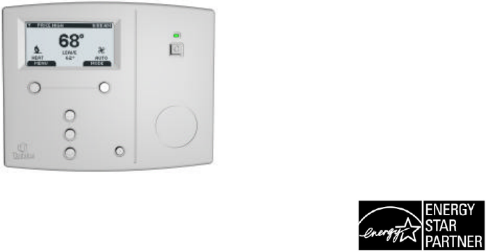
Tantalus ST-1480 Smart Thermostat
Operating and
Installation Manual
© All Rights Reserved

Page
2
Page
3
Operating and
Installation Manual
Congratulations on the purchase of your new thermostat. It has been designed for easy
programming to save you on energy costs and allow a comfortable living environment.
Features:
• Auto Mode programming of your yearly Heating and Cooling needs
• Easy adjustment of temperature and schedule
• EnergyStar® compliant presets to help reduce heating and cooling costs
• Wirelessly communicates with your utility
• Notifies you and automatically responds to utility demand response programs
• Single button Conserve Mode operation
• Large, easy to read backlit display
• Silent operation
• Protection against installation short circuits
Page
4
Table of Contents
OPERATING THE THERMOSTAT...........................................................................7
WORKING MODES ..............................................................................................................7
NORMAL OPERA TING MODE ............................................................................................8
NAVIGATING THE CONTROLS ..........................................................................................8
HOME SCREEN...................................................................................................................9
TITLE BAR.........................................................................................................................10
HELP BUTTON..................................................................................................................10
SETTING THE TIME..........................................................................................................11
DEFAULT SCHEDULE......................................................................................................12
TEMPORARY HOLD..........................................................................................................13
HEATING AND COOLING MODES ...................................................................................14
FAN MODES ......................................................................................................................15
TEMPERATURE SETTINGS .............................................................................................16
SCHEDULE........................................................................................................................18
PERMANENT, TIMED, AND VACATION HOLDS ..............................................................19
TEMPERATURE UNITS AND CALIBRATION ...................................................................21
SERVICE INFORMATION .................................................................................................22
USER OPTIONS ................................................................................................................23
LANGUAGES .................................................................................................................23
Page
5
SCHEDULE....................................................................................................................23
CHANGE FILTER REMINDER.......................................................................................24
POWER OUTAGES ...........................................................................................................24
THERMOSTAT CONSERVATION MODE .........................................................................25
USER CONSERVE MODE.............................................................................................26
UTILITY CONSERVE MODE.........................................................................................28
INSTALLATION AND MAINTENANCE..................................................................30
MOUNTING THE THERMOSTAT......................................................................................30
MOUNTING THE REMOTE SENSORS .............................................................................30
CLEANING THE THERMOSTAT.......................................................................................30
REMOVING THERMOSTAT FRONT HOUSING FROM BACKPLATE..............................31
REPLACING THE BATTERY..........................................................................................31
WIRING CONFIGURATION...............................................................................................32
SETUP MENU OPTIONS ...................................................................................................34
PASSWORD...................................................................................................................34
SETPOINT RANGE........................................................................................................35
EQUIPMENT TYPE........................................................................................................35
EQUIPMENT SETTINGS ...................................................................................................36
CONVENTIONAL SYSTEMS .........................................................................................36
HEAT PUMP SYSTEMS .................................................................................................37
CONTROL OPTIONS .........................................................................................................38
Page
6
RESET ...............................................................................................................................39
CONVENTIONAL SYSTEM TEST .....................................................................................40
HEAT-PUMP SYSTEM TEST ............................................................................................41
PRODUCT CONFORMITY.................................................................................................42
NOTES ...............................................................................................................................43
Page
7
OPERATING THE THERMOSTAT
Working Modes
The thermostat has two working modes:
• Normal Operating Mode : In this mode you can program the SETPOINT temperatures,
the schedules and remaining parameters of the thermostat configuration.
• Conservation Mode : When set in this mode by either you or through a remote request
from your utility, the scheduled SETPOINT values are modified to save energy; you
cannot modify any settings that may affect the objective temperatures or the HVAC
equipment operation.
Page
8
NORMAL OPERATING MODE
Navigating the Controls
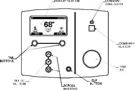
The function of the LEFT and RIGHT TAB buttons appears on the bottom of the display screen.
Use the SCROLL (? ?) buttons to move through the menu items and options, and to change
highlighted values. Press the SELECT (v) button to select or accept highlighted menu items. You
can always go back or cancel prior to saving changes.

Page
9
Home Screen
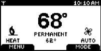
The Home Screen displays current temperature and operation data. To view this screen when the
backlight is off just press any of the buttons . Icons such as the heat or fan are animated when the
equipment is running.

Page
10
Title Bar
The current time is displayed in the upper right corner of the Title Bar while in the upper left corner
there is an icon showing the communications link status between the thermostat and the utility
meter:
means Link OFF, means Link ON,
The Title Bar also displays messages sent through the communications link to you by your utility
(e.g., the Electricity Rate).
HELP button
The HELP button provides you with information on how to navigate through the individual menu
screens. It will help you quickly change settings without referring to this user manual; however, it
does not replace it so please keep this manual for future reference.
? ?
Page
11
Setting the Time
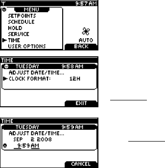
The current date and time need to be set at initial installation and after battery replacement. You
can change the day, time, enable a 24h clock readout, and change from daylight saving to standard
time by selecting TIME from the Main Menu. You can always change between 12H or 24H clock
format.
Press the Left Tab button on the home screen to view the Main
Menu
Use the SCROLL buttons to select the TIME menu.
Press SELECT to enter the TIME menu.
Use the SCROLL buttons to select between the ADJUST
DATE/TIME and the CLOCK FORMAT menus.
To change between 12 and 24 hour clock formats, press SELECT
on the CLOCK FORMAT menu item. The setting will be
underlined. You can change it using the SCROLL buttons and
then pressing SELECT.
To adjust the date and time, press SELECT on the ADJUST
DAY/TIME menu item.
The underlined selection will be changed using the SCROLL
buttons.
Press SELECT to move between hour and minute adjustment.
Press SAVE CHANGES to accept the new settings and return to
the TIME menu.

Page
12
Default Schedule
The thermostat’s Schedule is factory programmed in accordance with EnergyStar guidelines which
define the START TIMES and SETPOINTS listed below (Note that a SETPOINT is defined by a
NAME, and HEAT & COOL temperatures). The thermostat anticipates the time required to reach a
desired temperature prior to the start of the SETPOINT time; therefore, you only need to set the
desired time for the SETPOINT temperature.
SCHEDULE
Mon. to Fri. Sat. & Sun.
SETPOINT SETPOINT
START
TIMES
NAME HEAT COOL
START
TIMES
NAME HEAT COOL
6:00 am
Wake 70°F (21°C)
78°F (26°C)
8:00 am
Leave 62°F (17°C)
85°F (29°C)
8:00 am
Wake 70°F (21°C)
78°F (26°C)
6:00 pm
Return 70°F (21°C)
78°F (26°C)
10:00 pm
Sleep 62°F (17°C)
82°F (28°C)
11:00 pm
Sleep 62°F (17°C)
82°F (28°C)
Page
13
Temporary HOLD
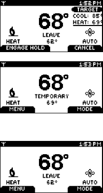
You temporarily adjust the temperature warmer or cooler, without affecting the pre-set
programming, through the use of a temporary hold. The thermostat will remain at the temporary
HOLD temperature until the next scheduled SETPOINT.
From the home screen, press either of the SCROLL buttons to
view this screen. Continue to press either of the SCROLL buttons
to highlight the operating target SETPOINT (HEAT or COOL),
which will be underlined.
Press the SELECT button to toggle between the HEAT and COOL
temperatures.
Set the desired temperature using the SCROLL buttons.
Press the LEFT TAB to ENGAGE HOLD, or RIGHT TAB to
CANCEL and return to the normal Home Screen.
When TEMPORARY HOLD is engaged the screen will be as shown below:
To cancel a HOLD, press a SCROLL button to return to this
screen.
Press the RIGHT TAB to CANCEL HOLD, or LEFT TAB to
ENGAGE HOLD (continue the HOLD) and return to the normal
Home Screen.
Page
14
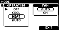
Heating and Cooling Modes
The thermostat is pre-set for heating operation (HEAT). You can manually change the operating
mode between AUTO, HEAT, COOL, OFF, and, for heat pump applications with auxiliary heat,
EMERG.
Press the RIGHT TAB button on the home screen to view this
screen.
Use the SCROLL buttons to select the desired operating mode.
Press SELECT to engage the operating mode.
AUTO: The thermostat automatically selects heating or cooling depending on the indoor
temperature.
HEAT: The thermostat controls only the heating system.
COOL: The thermostat controls only the cooling system.
OFF: Heating and cooling systems are off.
EMERG: Note: only for heat pumps with auxiliary heat. The thermostat only controls the
Emergency (Auxiliary) heat which leaves the heat pump’s compressor locked out.
Use this setting only when you suspect the heat pump is out of service or the
outdoor conditions render inefficient the operation of the heat pump.
Page
15
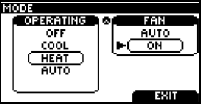
Fan Modes
You can manually change the fan mode between AUTO and ON.
Press the Right Tab button on the home screen to view this
screen
SCROLL through the operating modes to get to the fan
modes, then press SELECT to engage the desired fan mode.
AUTO: The fan runs only when the heating, cooling, or emergency systems are on. For
conventional systems with the option FAN ON IN HEAT set to NO, the fan is not controlled by the
thermostat but by the furnace.
ON: The fan runs continuously.
Page
16
Temperature Settings
A SETPOINT is defined by a NAME, and HEAT & COOL temperatures.
Example: If the SETPOINT is set to WAKE, a thermostat operating in AUTO mode will keep your
dwelling’s temperature at the predefined HEAT or COOL temperature. In the summer, the
thermostat will COOL your dwelling down to 78°F. In the fall, the thermostat will engage the HEAT
mode, heating your dwelling up to 70°F throughout the winter. In the spring, when temperatures rise
again, the thermostat will change back to COOL mode.
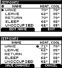
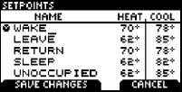
The SETPOINT’s HEAT and COOL temperatures can be changed using the SETPOINTS screen.
Choose SETPOINTS from the Main Menu to view this screen.
To change the HEAT and COOL temperature settings, SCROLL
to the SETPOINT you want to change and press SELECT.
SCROLL to change the temperature, or press SELECT to move
between the HEAT and COOL settings.
Press the LEFT TAB to SAVE temperature changes.
Page
17
Temperature Settings (continued)
To change the name of a SETPOINT, press EDIT NAME and
change the SETPOINT’s name by using the SCROLL and
SELECT buttons. Use SELECT to move the cursor to the next
position and SCROLL to find the desired letter or blank (empty)
character.
Page
18
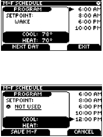
Schedule
The SCHEDULE determines when a SETPOINT such as WAKE begins. Only the start times are
defined. The SETPOINT ends when the next SETPOINT starts. To delete a start time, SCROLL
down the list of start times, and SELECT it; press SELECT again to underline the associated
SETPOINT name and SCROLL until NOT USED is underlined, i.e. the SETPOINT will be NOT
USED in this case.
The PROGRAM window displays the SETPOINT associated
with the start time on the right.
Adjust the start time by pressing SELECT and SCROLLING
the time.
Press SELECT to move within the PROGRAM window. Here
the SETPOINT can be SCROLLED to choose the name of a
different SETPOINT.
Press SELECT to return to the start times on the right.
You can have up to 6 scheduled start times.
To add a start time, SCROLL to a blank row, SELECT it, and
change the start time.
Change the name NOT USED to an appropriate SETPOINT
after you have added the start time.
Choose SCHEDULE from the main MENU to view this
screen.
Page
19
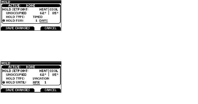
Permanent, Timed, and Vacation HOLDs
The SCHEDULE can be modified to maintain a desired SETPOINT through either a:
• Permanent HOLD (HOLD until cancelled)
• Timed HOLD (HOLD for 1 to 99 hours, or 1 to 99 days)
• Vacation HOLD (HOLD until a set date)
Choose HOLD from the main Menu then select the HOLD TYPE, press SELECT, then SCROLL to
the desired HOLD TYPE and press SELECT again.
Permanent HOLD
Using the arrow keys, change the HOLD TYPE to
PERMANENT and press the SELECT key. SCROLL to the
line above HOLD TYPE and press the SELECT key again,
scroll to choose the desired SETPOINT NAME.
Press SAVE CHANGES to accept the new settings and
initiate the HOLD. To cancel the HOLD, return to the HOLD
menu and press CANCEL HOLD.
Page
20
Permanent, Timed, and Vacation HOLDs (continued)
Timed HOLD
In TIMED HOLD, choose between 1 and 99 (in hours or
days). You can also choose the SETPOINT to HOLD.
Press SAVE CHANGES to accept the new settings and
initiate the HOLD.
To cancel the HOLD, return to the HOLD menu and press
CANCEL HOLD.
Vacation HOLD
Choose the HOLD UNTIL date in VACATION HOLD. You
can also choose the SETPOINT to HOLD.
Press SAVE CHANGES to accept the new settings and
initiate the HOLD.
To cancel the HOLD, return to the HOLD menu and press
CANCEL HOLD.
Page
21
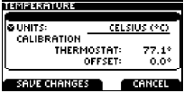
Temperature Units and Calibration
The display can be set to display Fahrenheit (°F) or Celsius (°C) units. If you measure the
temperature yourself or believe this thermostat’s displayed temperature is off slightly, then you can
easily calibrate the thermostat’s display temperature by up to +/- 5.4°F (+/- 3°C) using these steps.
SELECT TEMPERATURE from the Main Menu.
Change the UNITS by pressing SELECT on the UNITS line,
then SCROLL between FAHRENHEIT (°F) and CELSIUS (°C).
To calibrate the thermostat, select the OFFSET line. Press
SELECT, then SCROLL to change the offset.
Press SAVE CHANGES to accept the new settings.
Page
22
Service Information
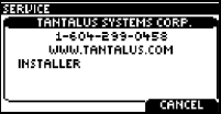
Information regarding your service contractor can be programmed into the thermostat for future
reference.
Choose SERVICE INFO from the main Menu.
Press EDIT NAME and enter the name and contact
information using the SCROLL and SELECT buttons .
After pressing SAVE CHANGES scroll to the next line if you
need to enter additional information; then follow the
procedure just described.
Page
23
User Options
Languages
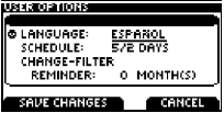
The thermostat can be set to English or Spanish through the USER OPTIONS menu.
To change from ENGLISH to SPANISH, SCROLL to
the USER OPTIONS on the Main Menu.
Press SELECT on the LANGUAGES line. SCROLL
to the ESPA ÑOL choice (underlined).
Press SAVE CHANGES to save.
Schedule
There are three choices for the weekly schedule. To change between the three scheduling options,
SELECT the SCHEDULE line in the USER OPTIONS menu, and SCROLL between these three
choices:
5/2 DAYS Mon. – Fri. schedule is the same. Sat. & Sun. schedule is the same
7 DAYS Every day of the week has an individual schedule.
5/1/1 DAYS Mon. – Fri. schedule is the same. Sat. has an individual schedule, and
Sun. has an individual schedule.
Page
24
Change Filter Reminder
A CHANGE FILTER reminder may also be set in the USER OPTIONS menu. It can be set from 0
to 12 months. Setting it to 0 months effectively disables the CHANGE FILTER reminder.
After the CHANGE FILTER reminder is enabled, the value shown by this screen will decrease each
month. When it reaches 0, the CHANGE FILTER reminder alarm appears. You can clear the alarm
by touching CLEAR ALARM. In order to re-enable the CHANGE FILTER reminder, set the desired
period and touch SAVE CHANGES.
Power Outages
In the event of a power failure, the thermostat will retain information for proper operation of the
heating and cooling equipment as well as maintaining the time. It will not display information on the
display screen during the power outage. Once power is restored, the thermostat will resume
operation maintaining all previously stored settings.
Page
25
THERMOSTAT CONSERVATION MODE
The Conservation Mode of the thermostat allows either you or your utility to modify scheduled and
HOLD SETPOINTs to reduce energy consumption.
There are two Conservation Modes: User Conserve and Utility Conserve.
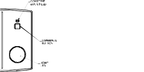
These controls are active when in the Conservation Mode:
• CONSERVE Status Light
• CONSERVE Button
• HOME Led
Page
26
User Conserve Mode
You can initiate the User Conserve Mode in your thermostat by pressing the Conserve Button. This
action will turn ON the Conserve Status light Green.
The purpose of the User Conserve Mode is to save energy by incrementing, in the case of Cooling,
or decrementing, in the case of Heating, the scheduled target temperature by a specified fixed
value.
If a temporary HOLD or the current scheduled SETPOINT expires, the incremental temperature
change is applied to the next scheduled SETPOINT.
Note that you will not be able to change any scheduled or HOLD SETPOINTs while you are in the
User Conserve Mode, you will have to exit this mode before you can make those changes.
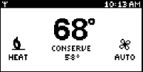
At this point, the thermostat will set back the current SETPOINT
(HOLD or scheduled SETPOINT) by a fixed value of 1°C to
conserve energy. The SETPOINT’s name at the Home Screen of
the thermostat will be replaced by a label showing “Conserve”.
Page
27
During the Conserve Mode you will only be able to modify the following parameters:
Language
24 hour Time Format
Change Filter Reminder
Contact Information
Exit from User Conserve Mode
To exit the User Conserve Mode, press the Conserve Button again and the thermostat will go back
to its regular schedule or applicable HOLD. The Green Conserve Status light will turn OFF.
When the thermostat exits the User Conserve Mode, it enters the Normal Operation Mode, w here
the SETPOINTs are as programmed by the Schedule or HOLD and you are able again to modify
any configuration parameter of the thermostat.
Page
28
Utility Conserve Mode
If your utility offers a energy reduction plan and you are enrolled in the program, your utility can
start a Utility Conserve Mode. This allows your utility to send a signal over the communications link
to increment the temperature a few degrees (when using the cooling system) or decrement it a few
degrees (when using the heating system).
If a temporary HOLD or the current scheduled SETPOINT expires, the incremental temperature
change is applied to the next scheduled SETPOINT.
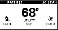
At this point, the thermostat will set back the current SETPOINT
(HOLD or scheduled SETPOINT) by a fixed value of 2°C to
conserve energy. The SETPOINT’s name at the Home Screen of
the thermostat will be replaced by a label showing “Conserve”.
When entering a Utility Conserve Mode, your thermostat will show
the word “UTILITY” under the room temperature and the Conserve
Status Light turns on Amber
Page
29
Note that you will not be able to change any scheduled or HOLD SETPOINTs while you are in the
Utilty Conserve Mode, you will have to exit this mode before you can make those changes.
During the Utility Conserve Mode you will only be able to modify the following parameters:
Language
24 hour Time Format
Change Filter Reminder
Contact Information
Exit from Utility Conserve Mode
The Utility Conserve Mode ends when your utility sends a signal to the thermostat to end the Utility
Conserve Mode, or y ou opt-out of the Utility Conserve Mode by pushing the Conserve Button.
In the case you opt-out of the Utility Conserve Mode, you will not be able to go back to it. The only
Conserve Mode you will be able to enter is the User Conserve Mode
When the thermostat exits the Utility Conserve Mode, it enters the Normal Operation Mode, w here
the SETPOINTs are as programmed by the Schedule or HOLD and you are able again to modify
any configuration parameter of the thermostat.

Page
30
INSTALLATION AND MAINTENANCE
The thermostat must be in the Normal Operating Mode in order to access to the configuration
settings required for the installation and maintenance.
Mounting the Thermostat
Install the thermostat at 5 feet (1.5m) above the floor in an area with good air circulation at average
temperature. Avoid locations with drafts or dead spots behind doors, hot or cold air ducts, sunlight
or radiant heat from appliances, concealed pipes or chimneys and unconditioned areas such as
outside walls behind the thermostat.
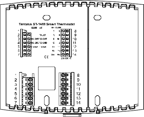
The 2 wallplate anchors should be spaced 3.5 inches (90 mm) apart in a vertical direction. Pull
wires through the backplate and connect to the appropriate terminals as defined in the Wiring
Configuration.
Mounting the Remote Sensors
Outdoor sensors should be mounted in shaded locations, out of direct sunlight. The thermostat will
automatically detect an external sensor and display its readings.
Cleaning the Thermostat
The thermostat can be cleaned with a soft cloth lightly dampened with isopropyl alcohol (IPA).
Excessive IPA or use of other solvents may damage the LCD!
Page
31
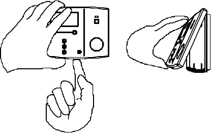
Removing Thermostat Front Housing from Backplate
To remove the thermostat front housing from the backplate, press the plastic tab located at the
bottom of the thermostat. Pull the bottom of the front housing forward and remove.
Replacing the Battery
A LOW BATTERY WARNING will appear when the battery falls below 10% of its rated capacity.
This procedure does not lose the thermostat settings; however, time settings will require re-
programming. Replace with a CR-2032 battery.
Warning: Do not use metallic tools when removing battery or backplate; this may damage the
thermostat.
Page
32
Wiring Configuration
See Wiring Table on the next page.
Page
33
Wiring Configuration (Continued)
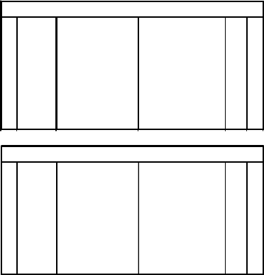
This thermostat should be wired by a licensed technician familiar with HVAC installation.
1Common(GND) C8
2Power (24VAC) R9
3 RS OUT Outdoor Sensor 1st Stage Heat W1 10
4 RS GND Sensor Ground Fan G11
5 FILTER Filter 1st Stage Cool Y1 12
6 2nd Stage Cool Y2 13
7 2nd Stage Heat W2 14
1Common (GND) C8
2 FAULT Heat Pump Fault Power (24VAC) R9
3 RS OUT Outdoor Sensor Auxiliary Heat E10
4 RS GND Sensor Ground Fan G11
5 FILTER Filter 1st Stage Heat Pump Y1 12
6 2nd Stage Heat Pump Y2 13
7Changeover Valve O/B 14
Conventional Systems (CONV)
Heat Pump Systems (HP)
Page
34
Setup Menu Options
WARNING: Changing settings in the SETUP can damage the HVAC system and should only be
done by a qualified HVAC technician.
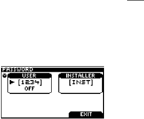
Password
Two levels of password protection are programmed in this thermostat: USER and INSTALLER.
Both password levels will timeout after 20 minutes of the last button press and force you to re-enter
a password.
The default INSTALLER password is INST. The INSTALLER password limits access to critical
thermostat settings which include:
• Password • Equipment Settings
• SETPOINT Range • Control
• Equipment Type • Reset
The passwords can be changed in the PASSWORD menu.
SCROLL to change either USER or INSTALLER password.
SCROLL through the letters to change the password, or use
the blank letter to set the password to a blank.

Page
35
SETPOINT Range
The SETPT RANGE sub menu defines the Maximum and Minimum temperatures allowed in the
HEAT and COOL modes. Adjusting these temperatures limits the temperature ranges allowed
when setting SETPOINT temperatures.
Equipment Type
WARNING: The thermostat must be configured correctly to match the equipment type. The number
of cooling and heating stages must be defined in the Conventional or Heat Pump setting.
EQUIPMENT TYPE DEFAULT OPTION
CONVENTIONAL # OF COOL STAGES 0 0-2
# OF HEAT STAGES 1 0-2
HEAT PUMP # OF COOL STAGES 1 1-2
# OF HEAT STAGES 1 1-3*
REV. VALVE ON IN COOL ON IN HEAT
*For Heat Pumps, defining one more heat stage than cool stages means that Emergency Heat
(Auxiliary Heat) is installed.

Page
36
Equipment Settings
Conventional Systems
You must enter an Installer Password to access the EQUIPMENT SETTINGS from the Main Menu.
The following settings can be changed for Conventional Systems:
DEFAULT OPTION
MIN ON/OFF TIME 3 MIN 1-6 MIN
Minimum cycle time for the furnace/air conditioner.
FAN ON IN HEAT YES NO
(this option only
applies to the furnace)
The fan turns on when the
thermostat sends the fan on
signal. If the Fan Mode is
AUTO the thermostat will turn
the fan on whenever the furnace
is turned on.
The furnace waits until enough
heat is built up before turning on
the plenum fan. The furnace
controls the fan when the Fan
Mode is AUTO.
Page
37
Heat Pump Systems
You must enter an Installer Password to access the EQUIPMENT SETTINGS from the Main Menu.
The following settings can be changed for Heat Pump Systems:
DEFAULT OPTION
MIN ON/OFF TIME 3 MIN 1-6 MIN
Minimum cycle time for the heat pump/auxiliary heater.
ALLOW HP+AUX ON YES NO
Allows the Heat Pump and
Auxiliary Heat to be on at the
same time.
Does not allow Heat Pump and
Auxiliary Heat to be on at the same
time (add-on configuration).
BALANCE POINTS HIGH 122°F (50°C) -38 – 122°F
-39 – 50°C
The High Balance Point defines the outdoor temperature above which
the Auxiliary Heater is disabled. An external temperature sensor must
be installed for the Balance Points to operate.
LOW -40°F (-40°C) -40 – 120°F
-40 – 49°C
The Low Balance Point defines the outdoor temperature below which
the Heat Pump compressor is disabled. An external temperature
sensor must be installed for the Balance Points to operate.
Page
38
Control Options
You must enter an Installer Password to access the CONTROL menu from the Main Menu. The
following settings can be changed:
DEFAULT OPTION
CHANGE
HYSTERESIS 2°F (1°C) 0-6°F
(0-3°C)
Defines the number of degrees the temperature must go beyond a
SETPOINT prior to changing from HEAT to COOL mode or vice versa
in AUTO mode.
ANTICIPATION TIME 60 MIN 0 – 180 MIN
The time limit the thermostat is allowed to engage the equipment to
reach a desired temperature. The algorithm determines the time
required to reach the temperature, and engages the equipment prior to
the next Scheduled SETPOINT in order to reach the desired
temperature at the appropriate time. The temperature may not be
reached if the ANTICIPATION TIME is less than the time required to
heat (or cool) to the desired temperature.
MAX RECOVERY
TIME 90 MIN 0 – 180 MIN
The maximum time the thermostat allows the equipment to reach a
desired temperature in 1ST stage heating (or cooling). If the thermostat
determines that the desired temperature will not be reached, it will
engage the second (or further) stage of heating (or cooling).
Page
39
Reset
A SETPOINT’s RESET restores the thermostat’s default EnergyStar SETPOINTs.
A FULL SYSTEM RESET restores the thermostat to the following original manufacturer settings.
HEAT COOL
WAKE 70ºF 78ºF
LEAVE 62ºF 85ºF
RETURN 70ºF 78ºF
SLEEP 62ºF 82ºF
UNOCCUPIED 62ºF 85ºF
OCCUPIED 70ºF 78ºF
SETPOINT 7 62ºF 85ºF
SETPOINTS
SETPOINT 8 62ºF 85ºF
LANGUAGE ENGLISH
USER OPTIONS CHANGE FILTER REMINDER 0 MONTH(S)
TEMPERATURE UNITS FAHRENHEIT (ºF)
USER INSTALLER
PASSWORD PRESET [1234] OFF [INST]
MAX MIN
HEAT 93ºF 41ºF SETPOINT RANGE COOL 95ºF 43ºF
# OF COOL STAGES 1
EQUIPMENT TYPE CONVENTIONAL # OF HEAT STAGES 1
MIN ON/OFF TIME 3 MIN
EQUIPMENT SETTINGS FAN ON IN HEAT YES
CHANGE HYSTERESIS 2ºF
ANTICIPATION 60 (MINUTES) CONTROL
MAX RECOVERY TIME 90 (MINUTES)
OPERATING FAN
MODE HEAT AUTO

Page
40
Conventional System Test
This procedure allows the installer to bypass delays associated with the minimum on/off times.
OUTPUT TESTED PROCEDURE EXPECTED RESULT
Fan Mode = Off
Fan = change from AUTO to ON Fan should turn on and off
1ST stage cooling
Mode = COOL
Modify the temperature by - 5°F (-3°C)
from room temperature and SELECT
ENGAGE HOLD
First stage cooling should
engage
2ND stage cooling* Remain in COOL mode
Return to the Temporary HOLD function
and SELECT ENGAGE HOLD again
Second stage cooling
should engage
1ST stage heating Change mode to HEAT and modify the
temperature by +5°F (+3°C) and
ENGAGE HOLD
First stage heating should
engage
2ND stage heating** Remain in HEAT mode and return to the
Temporary HOLD function and SELECT
ENGAGE HOLD
Second stage heating
should engage
* Only in two stage cooling systems.
** Only in two stage heating systems.
Page
41
Heat-Pump System Test
This procedure allows the installer to bypass delays associated with the minimum on/off times.
OUTPUT TESTED PROCEDURE EXPECTED RESULT
Fan Mode = Off
Fan = change from AUTO to ON Fan should turn on and off
1ST stage cooling
Mode = COOL
Modify the SETPOINT by at least 5°F
(3°C) below room temperature and
SELECT ENGAGE HOLD
First stage cooling should
engage
2ND stage cooling* Remain in COOL mode
Return to the Temporary HOLD function
and SELECT ENGAGE again
Second stage cooling should
engage
1ST stage heating
Mode = HEAT
Modify the SETPOINT by at least 5°F
(3°C) above room temperature and
SELECT ENGAGE HOLD
First stage heating should
engage
2ND stage heating** Remain in HEAT mode
Return to the Temporary HOLD function
and SELECT ENGAGE HOLD again
Second stage heating should
engage.
Heating using
Auxiliary Heat**
Remain in HEAT mode
Return to the Temporary HOLD function
and SELECT ENGAGE HOLD again
Auxiliary heating should
engage (if there are more heat
stages than cool stages)
* Only in two stage heat pump systems;
** Only with Heat-Pump systems equipped with an Auxiliary Heater.
Page
42
Product Conformity
This equipment, if installed in strict accordance with the manufacturer’s instructions, complies with
the limits for a Class B computing device pursuant to Part 15 of FCC rules.
This equipment, if installed in strict accordance with the manufacturer’s instructions, complies with
the requirements of IEC 60730-1 for EMC emissions and immunity.
This equipment is RoHS compliant.
The battery in this thermostat may contain perchlorate material - special handling may be
necessary.
www.dtsc.ca.gov/hazardouswaste/perchlorate
Changes or modifications not expressly approved by the party responsible for compliance could
void the user’s authority to operate the equipment.
Page
43
Notes