Tantalus Systems XR3001 Remote Transceiver User Manual XR 3100 inst manual dec1
Tantalus Systems Corp Remote Transceiver XR 3100 inst manual dec1
users manual

Tantalus Utility Network®
XR-3100
Crossband Repeater
Installation Guide
.

i
LEGAL NOTICES
Notice
The information contained in this document is subject to change without notice.
Warranty
Tantalus makes no warranty of any kind with regard to this material, including, but not limited to the
implied warranties of merchantability and fitness for a particular purpose. Tantalus shall not be
liable for errors contained herein or incidental consequential damages in connection with the
furnishing, performance, or use of this material.
Copyright Statement
© 2005 Tantalus Systems Corp. All rights reserved.
No part of this publication, or any software included with it may be reproduced, stored in a retrieval
system, or transmitted in any form or by any means including photocopying, electronic, mechanical,
recording or otherwise without the prior written permission of the copyright holder. This document
contains proprietary information of Tantalus Systems Corp. The contents are confidential and any
disclosure to persons other than the officers, employees, agents or subcontractors of the owner or
licensee of this document, without the prior written consent of Tantalus Systems Corp. is strictly
prohibited.
Trademark
Tantalus Utility Network® is a Registered Trademark and TUNet™ is a Trademark of Tantalus
Systems Corp.
Corporate Contact Info
US Office
Tantalus Systems Corp.
2410 Flints Pond Circle
Apex, NC
USA 27523
T/ 919.639.4502
F/ 919.573.0323
Canada Corporate Office
Tantalus Systems Corp.
100 - 2955 Virtual Way
Vancouver, BC
Canada V5M 4X6
T/ 604.299.0458
F/ 604.451.4111
Sales Inquiries
TantalusSales@tantalus.com
Technical Support
TantalusTechsupport@tantalus.com
General Information
TantalusInfo@tantalus.com

ii
COMMUNICATIONS REGULATION INFORMATION
RF Exposure
Professional installation of this device is required. The radio equipment described in this guide
emits radio frequency energy. Although the power level is low, the concentrated energy from a
directional antenna may pose a health hazard. The following minimum distances apply in both
indoor and outdoor environments.
This device uses a 220 MHz (Part 90) internal antenna and the device must be mounted such that
a Minimum Distance of 20 cm from the top of the device is maintained from the general public.
This internal antenna can be replaced with one of the external antennas shown in the table below.
Only the antennas listed in this section are approved for use with this device.
Table 1 Table of External Antenna Gain for Transceiver
Part No. dBi Minimum Distance from
the General Public.
AE-3010 5.2 23 cm
AE-3020 9.1 35 cm
More information on RF exposure is available at http://www.fcc.gov/oet/info/documents/bulletins.
UL/CSA Notice
The transceiver has been recognized for use the Canadian Standards Association (CSA). The CSA
Certification is in accordance with CSA CAN/CSA C22.2 No. 60950-1-03 & ANSI/UL 60950-1-2002.
UL/CSA Conditions of Approval
This device is approved for use in locations that are rated Overvoltage category I through III (IEC
60664-1). Equipment with an impulse withstand voltage corresponding to overvoltage category III is
for use in the fixed installation downstream of, and including the main distribution board, (IEC
60364-4-443).
The transceiver is not acceptable as a standalone unit. It must be mounted within the following
conditions of approval:
1. Installation, operation and maintenance of the transceiver should be in accordance with the
transceiver’s installation manual, and the National Electric Code.
2. When installed, this equipment must be protected with an external disconnect device and
branch circuit current protection with a maximum rating of 15A. A circuit breaker rated at 15A
satisfies both requirements.
3. When the unit cannot have the AC supply sourced from an Overvoltage category III
installation, a transient voltage surge suppressor must be installed before the unit to reduce
the peak transient surge rating.
4. Tampering or replacement with non-factory components may adversely affect the safe use of
the transceiver and will void the approval.

iii
5. Use of batteries that are not Tantalus-approved may adversely affect the safe use of the
transceiver, and will void the approval.
FCC Part 15 Notice, USA
The transceiver described herein complies with Part 15 of the FCC Rules. Operation is subject to
the following two conditions:
1. This device may not cause harmful interference.
2. This device must accept any interference received, including interference that may cause
undesired operation.
This device is specifically designed to be used under Section 15.247 of the FCC Rules and
Regulations. Any unauthorized modification or changes to this device without the express approval
of Tantalus Systems Corp. may void the user’s authority to operate this device.
Furthermore, this device is intended to be used only when installed in accordance with the
instructions outlined in this manual. Failure to comply with these instructions may also void the
user’s authority to operate this device.
Radio and Television Interference
The installation guidelines are designed to provide reasonable protection against harmful
interference in a residential installation. This equipment generates, uses and can radiate radio
frequency energy and, if not installed and used in accordance with the instructions, may cause
harmful interference to radio communications. However, there is no guarantee that interference will
not occur in a particular installation.
If this equipment does cause harmful interference to radio or television reception, which can be
determined by turning the equipment off and on, you are encouraged to try and correct the
interference by one of more of the following measures:
• Reorient or relocate the receiving antenna.
• Increase the separation between the equipment and receiver.
• Connect the equipment into an outlet on a circuit different from that to which the receiver is
connected.
• Consult the dealer or an experienced radio/TV technician for help.
Installing the Tantalus XR-3100 page 1
Version 1.03 , Released: 2005-12-09
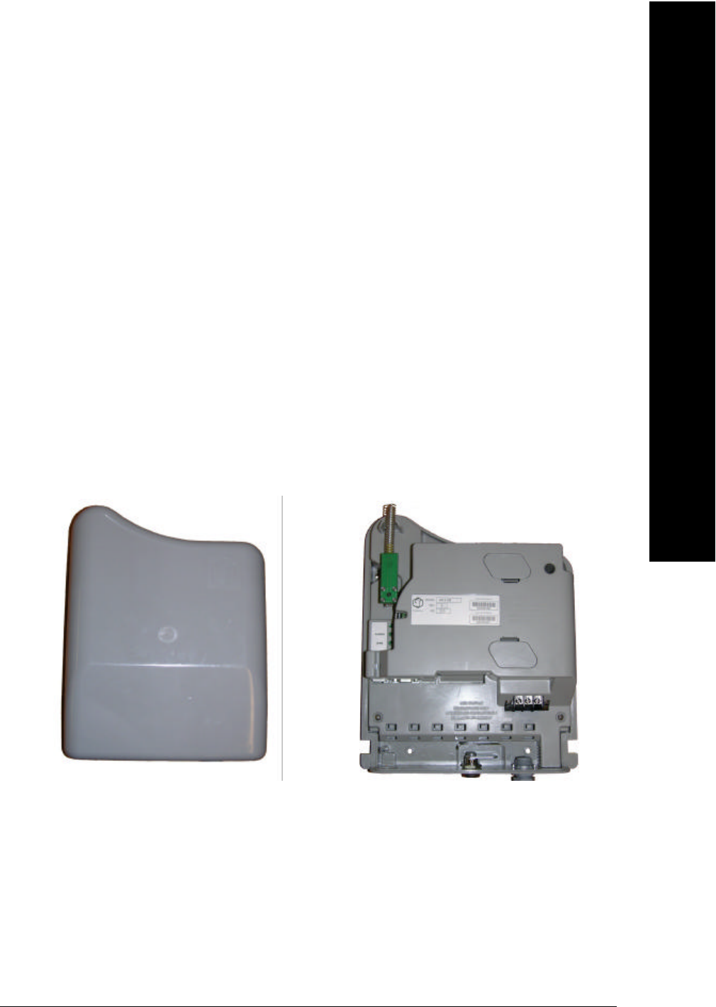
Product Description
The XR-3100 is a cross band repeater that transports TUNet traffic between the 220 MHz WAN
and the 900 MHz LAN. The XR-3100 provides additional flexibility when deploying a network:
• In hard to reach situations such as at range boundaries, where the device can be mounted
high up to extend reach.
• In hard to penetrate situations, such as in metal enclosures or basements, where the
device can be connected to an external antenna, allowing the TUNet signal to be directed
towards the Network Controller.
Description
.

page 2 Tantalus Systems Corp.
General Information
Tantalus provides two-way, real-time data communications networks to monitor and control electric
utilities. Our long-range wireless networks unite a utility’s applications, making meter reading, load
management, and distribution automation cost-effective and practical throughout urban and rural
service areas.
The Tantalus Utility Network uses long-range 220 MHz spectrum to deliver valued applications
such as outage management, power quality monitoring, meter reading, load management, and
distribution automation to utilities. The Network provides robust two-way communications
throughout a utility’s diverse service territory – including residential, commercial, and industrial.
Product Specification: XR-3100 Cross Band Repeater
Frequency Range 902-928 MHz frequency hopping, license exempt
220-222 MHz frequency agile, very narrow-band GFSK
Operating Temperature -22 to 140°F (-30 to +60°C)
Operating Humidity 5% to 95% non-condensing
Modulation GFSK
Power Supply 100-240VAC from AC line mains, 2 A max
Power Consumption Quiescent Power: 1.9 watts typical
Standby Power: 2 watts
Active Power: 12 watts (pulsed)
Transmitted RF Power: 5 watts
Outage Reporting Optional
220-222 MHz Antenna
(Part 90)
Internal: Standard
External: Optional
For more information about the antennas that are approved for use
with this device, see the table 1 on page ii.
900 MHz Antenna
(Part 15)
Not accessible to installer/operator.
Data rate 1600/3200 bps
Standards • FCC CFR Title 47 Part 15c (Intentional Radiators)
• ANSI C12.1:1995 Sections: 4.7.3.1 Insulation, 4.7.3.11
EFT/Burst, 4.7.3.3.1 Surge Immunity, 4.7.3.3.2 Ring Wave
Immunity
• CFR Title 47 Part 15b (Unintentional Radiators)
• CFR Title 47 Part 90, Sub-Part I & T (Private Land Mobile
Radio Services)
• CSA C22.2 60950-1 and ANSI/UL 60950-1-2002. (Product
Safety)
Installing the Tantalus XR-3100 page 3
Version 1.03 , Released: 2005-12-09
Installing the XR-3100
Before the XR-3100 is ready for installation in the field, it must be programmed in the Meter Shop.
Warning
Energized meters, meter sockets and distribution lines present the risk of
electrical shock. All work on this equipment should be performed by qualified
metering specialists or industrial electricians. Personnel working with this
equipment should follow all utility company established operation and safety
procedures.
PROGRAMMING INSTRUCTIONS FOR THE METER SHOP
Ensure that you have the latest version of Tantalus DT-150 software installed on your PC and that
you have your utility’s Business Identifier as supplied by Tantalus.
1. Remove the XR-3100 from the packaging and place it on a flat, stable surface. Retain the
packaging so you can re-package the device for the field once you have programmed it.
2. Unlock the XR-3100 and slide the front cover upwards until you can lift it free.
Warning
Do NOT remove the inner plastic cover of the XR-3100. Tampering with the
inner workings of this device may results in damage to the product or injury to
the installer and void the product warranty.
!
Caution
Ensure that both battery compartments are empty.
3. Attach a power cord to the terminal blocks.
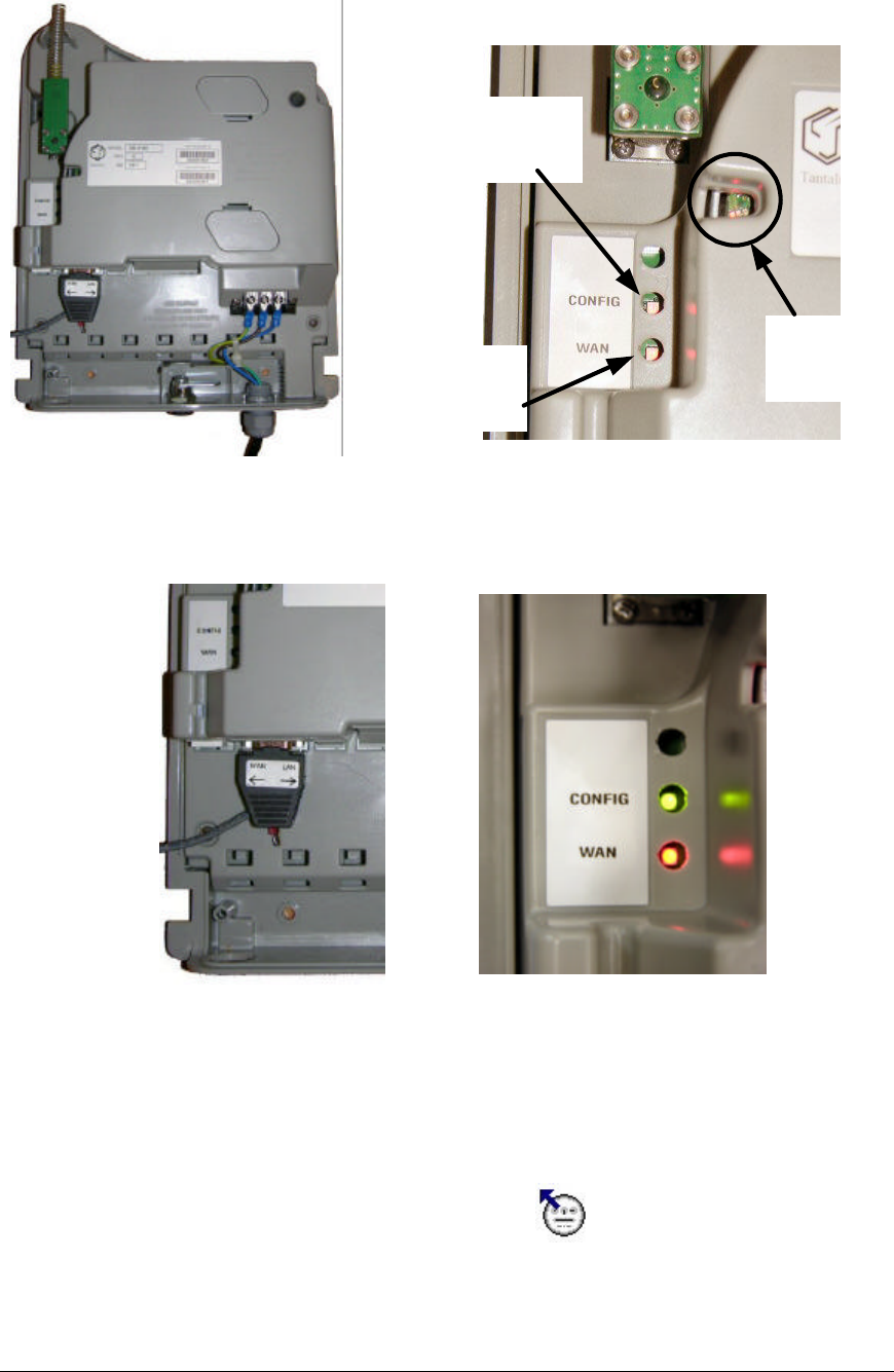
4. Attach the XR programming cable between your computer running the DT-150 software
and the XR-3100 serial programming port, as shown in Figure 1. Ensure that the toggle
switch on the programming cable is set to LAN as shown in Figure 3.
Installing
.
page 4 Tantalus Systems Corp.
WAN
STATUS
LED
LAN
STATUS
LEDs (3)
PROGRAMMING
CONFIGURATION
LED
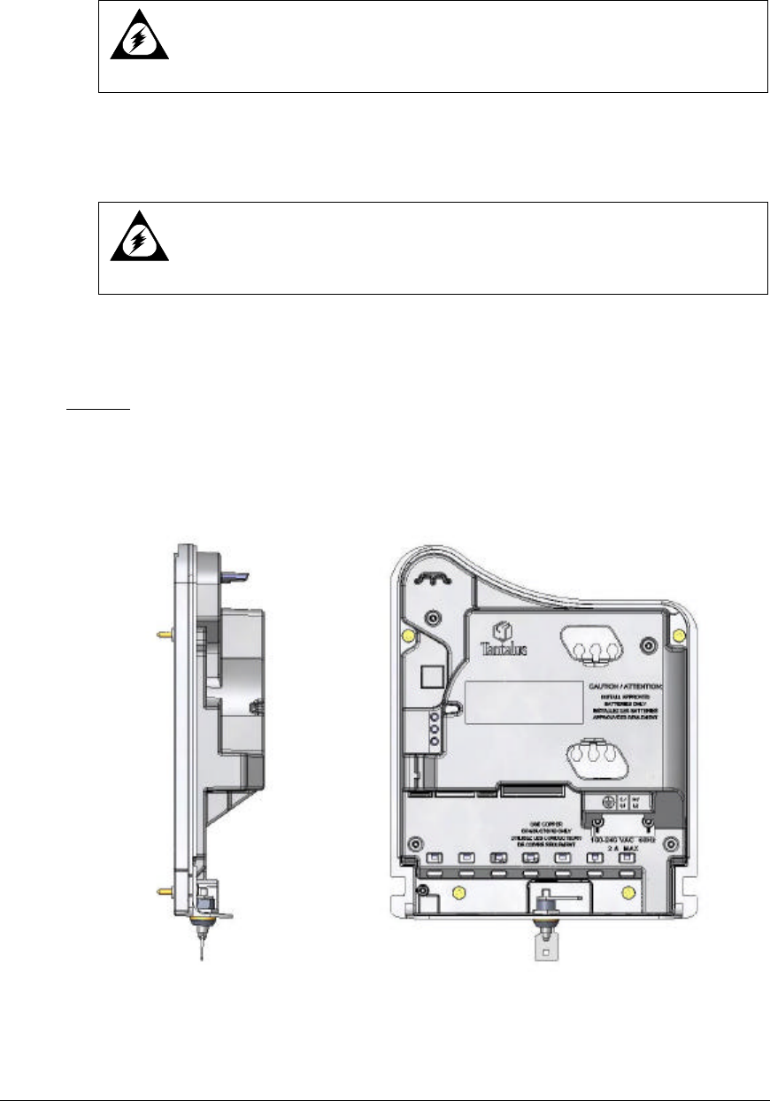
Figure 1 The XR-3100 serial port with the DT-
100 Cross band programming cable attached.
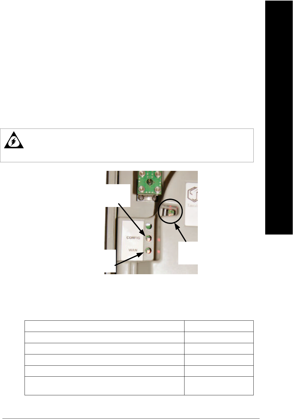
Figure 2 Position of the XR-3100 programming and status LEDs
Figure 3 Switch position to select the
LAN Controller.
Figure 4 The green programming CONFIG LED
indicating communication to the LAN Controller.
5. Plug in the power cord. The CONFIG LED should now be green as shown in Figure 4. If it
is red, immediately disconnect the power cord and check the toggle switch on the
programming connector.
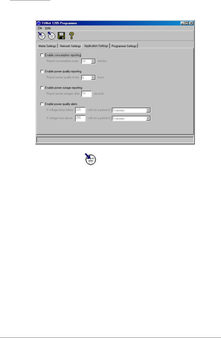
6. Start the DT-150 software. Click the read icon once. A new window will appear.
Should nothing come up then check all connections and settings.
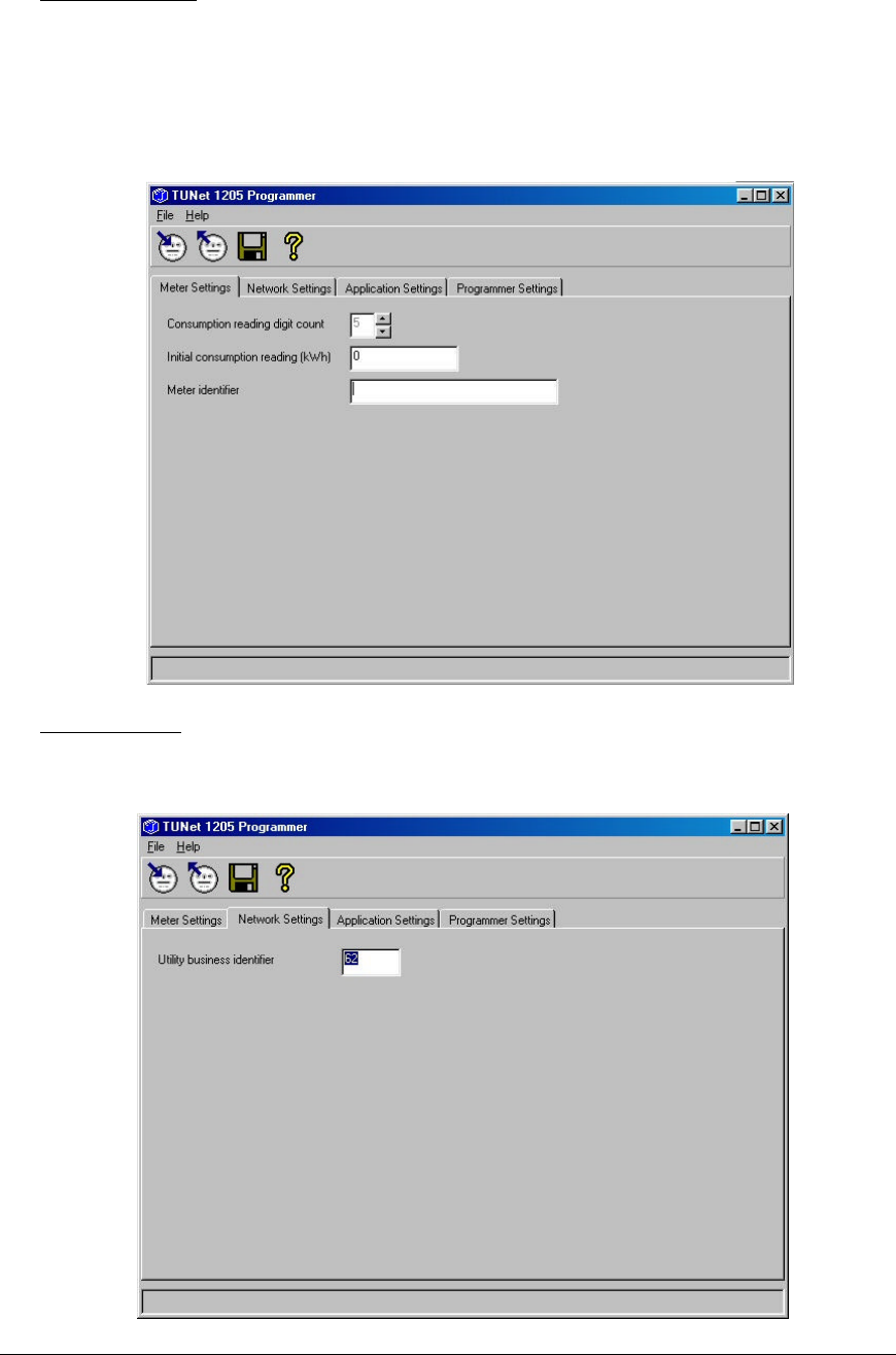
7. LAN Programming:
Installing the Tantalus XR-3100 page 5
Version 1.03 , Released: 2005-12-09
Meter Settings Tab
Consumption reading digit count: default
Initial Consumption reading: default
Meter Identifier: Enter a unique identifier for the unit, ie “Utility pole 12345”, “1234 Broadway Street”
Network Settings
Utility business identifier: Enter in the assigned business ID number for your utility provided by Tantalus.
page 6 Tantalus Systems Corp.
Application Settings
Uncheck all the boxes
8. Click the program icon . Now close the DT-150 program.
9. Unplug the XR-3100. Switch the toggle on the programming cable to the WAN position.
10. Unplug the cord and disconnect it from the terminal block.
11. Return the XR-3100 to the original packaging. Ensure that you include at least one battery
in the packaging with the device but do NOT install it in the XR-3100.
Installing the Tantalus XR-3100 page 7
Version 1.03 , Released: 2005-12-09
INSTALLATION INSTRUCTIONS FOR THE FIELD
Warning
This product should not be installed during heavy rain or snow as there may
pose a risk of electric shock.
1. Remove the XR-3100 from the packaging. Ensure that you have a battery for the device,
but do NOT install it until step 4.
Warning
1. Ensure that there is no power source connected to the XR-3100.
2. Ensure that both battery compartments are empty.
2. Remove the cover and mount the XR-3100 by one of the following methods:
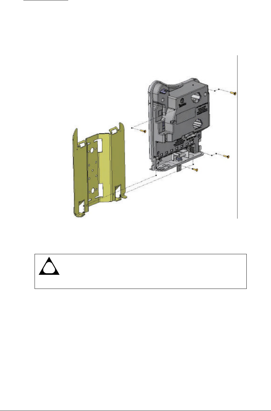
Flat wall:
The XR must be mounted to a flat surface that will engage all four mounting screws. This is
important to ensure adequate environmental sealing. The XR-3100 comes with 4 mounting screws
for mounting to wood or sheet metal.
page 8 Tantalus Systems Corp.
Mounting bracket:
The mounting bracket can be fixed to a utility pole by metal strapping or by threaded rod. The
bracket has also been designed to mount to horizontal poles and hand rails.
It is recommended to first mount the bracket first then mount the XR-3100 to the bracket using the
4 thread cutting screws that come with the bracket.
!
Caution
All 4 screws must be securely installed for protection against the
environment. Failure to do so will void warranty.
Installing the Tantalus XR-3100 page 9
Version 1.03 , Released: 2005-12-09
3. If you are using the supplied internal antenna, go to Step 4.
– or –
If you are installing the Tantalus-approved external antenna:
a. Remove the internal antenna by unscrewing the TNC plug from the TNC jack.
b. Remove the ½” trade knockout on the bottom left of the device. It is recommended to use
a utility knife, flat head screw driver and hammer to facilitate removal.
c. Run the coaxial cable from the outside of the box and up through the knockout. Connect
the cable to the TNC jack.
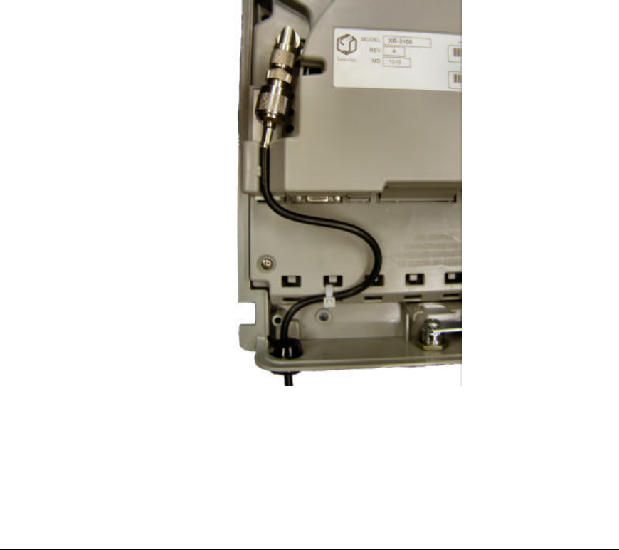
d. Ensure that there are several inches of strain relief available in the coax cable. Secure a
tie wrap to the slots in the inner cover.
e. Install the provided split cord grip fitting around the coax cable and insert into the
knockout. This fitting can accommodate multiple coax thickness. If the cable is too loose,
wrap electrical tape around the coax cable to provide a tighter fit in the cord grip fitting.
The device should now look like the one in Figure 5.
Figure 5 The XR-3100 with the strain relief correctly installed
f. Install the external antenna, lighting arrestor and mounting hardware according to the
supplied instructions and also taking note of the minimum safe operating distances for the
general public in Table 1 of the RF Exposure section on page ii.

page 10 Tantalus Systems Corp.
4. Install the battery in the XR-3100. Depress the battery cover tab, lift the cover, and install
the batteries (orientation not critical) with the exposed contacts inward.
!
Caution
Ensure that you are using a Tantalus-approved battery only.
Do NOT apply power to the XR-3100 until the battery has been installed.
5. Attach power to the XR-3100:
a. Connect the white power/neutral wire, black power wire, and green chassis ground wire to
the terminal block per the markings on the inner cover.
b. Ensure that there are several inches of strain relief available in the wires. Secure a tie
wrap to the slots in the inner cover.
6. Turn on the power.
7. Observe the LEDs on the left side of the XR-3100 to verify that two-way communication is
established.
• A green WAN LED indicates that the XR-3100 is operational.
For a description of the LEDs, turn to Troubleshooting the XR-3100 on page 11.
8. Attach the top cover by sliding the faceplate down over the device. The cover will snap
into place if correctly installed.
9. Engage the barrel lock.
Installing the Tantalus XR-3100 page 11
Version 1.03 , Released: 2005-12-09
Troubleshooting the XR-3100
Warning
Energized meters, meter sockets and distribution lines present the risk of electrical
shock. All work on this equipment should be performed by qualified metering specialists
or industrial electricians. Personnel working with this equipment should follow all utility
company established operation and safety procedures.
WAN LED STATUS INDICATORS
Start-up/Power up Solid RED
Scanning Flashing RED
Found Tantalus Channel Flashing ORG
Received message from Network Controller (one-way) Solid ORG
Received ACK to response to Network Controller (two-way) Solid GRN
Failed to receive ACK to subsequent response to Network
Controller (return to one-way) Solid ORG
WAN
STATUS
LED
LAN
STATUS
LEDs (3)
PROGRAMMING
CONFIGURATION
LED
Figure 6 Position of the XR-3100 programming and status LEDs
Troubleshooting
.

page 12 Tantalus Systems Corp.
LAN NETWORK STATUS LED (RED)
Start-up/Power up Solid RED
Module is not programmed Fast flashing RED
Unassociated/Re-associating Solid RED
Valid association candidate found Flashing RED
Full network association confirmed OFF
LAN APPLICATION MESSAGE TRANSACTION LED (GREEN)
Start-up/Power-up OFF
Message queued for transmission Long flash GRN
Valid message received (addressed to this device) Short flash GRN
LAN RF PACKET LED (AMBER)
Start-up/Power-up OFF
RF packet transmitted Long flash Amber
RF packet received (LAN activity) Short flash Amber
Check the WAN LED on the mid cover to ensure full two-way communication with the NC-2200.
If Then
The XR-3100 does not power up. Remove the unit and replace it with another one.
The XR-3100 powers up but does not
appear to find a Tantalus channel.
Remove the unit and replace it with another one.
When back in the Meter shop, ensure that the
Tantalus channel has been programmed in the scan
list.
The XR-3100 finds the Tantalus
channel but does not appear to be
addressed by the controller.
Contact the NC-2200 Administrator to verify that the
unit is being installed and the WAN Network ID has
been registered in the database. If it has not been
registered, ask that it be registered now.
If you still can’t get a signal and you are only using the internal antenna, try installing an external
antenna to the device to boost the signal strength.

Installing the Tantalus XR-3100 page 13
Version 1.03 , Released: 2005-12-09
Contact Information
TANTALUS SYSTEMS CORP.
100-2955 Virtual Way
Vancouver, BC
Canada V5M 4X6
Tel: 604-299-0458
Fax: 604-451-4111
Email: info@tantalus.com
Contact
.