Teac AG20D CAUTION User Manual To The 7f64c49f 04ea 4ae1 Bbe5 Ed4074af4c8b
7f64c49f-04ea-4ae1-b.. 7f64c49f-04ea-4ae1-bbe5-ed4074af4c8b
User Manual: Teac AG20D to the manual
Open the PDF directly: View PDF ![]() .
.
Page Count: 30
- IMPORTANT SAFETY INSTRUCTIONS
- CONNECTION
- FRONT PANEL INFORMATION
- REAR PANEL INFORMATION
- BASIC OPERATION
- SPEAKER CONFIGURATION, DELAY TIME & DYNAMIC RANGE CONTROL
- TEST TONE, LFE TRIMMER & CHANNEL SELECT
- AVAILABLE SURROUND MODE
- TROUBLESHOOTING
- AVR-320(NO BAND).pdf
- complete Service Agent list.pdf
- TEAC AG20D(AV4333with HDMI5.1 1 Mar 2007.pdf
- TEAC AG20D PAGE.pdf
- TEAC AG20D PAGE.pdf
- 1.pdf
IMPORTANT!
WWW.teac.com.au
WARRANTY INFORMATION INSIDE.PLEASE READ
TEAC AG20D
5.1 CHANNEL HOME THEATRE RECEIVER
USER MANUAL
ST EREO STATIO N AP S
VO LUME
PO WER
PH ONES TAPE AUX TU NER/BAND VI DEO 2VI DEO 1 DV D
DTS/
DO LBY DIGITA L 2C H DIGITAL IN
SU RROUND
MO DE SUB ON/OFF
RE SET
AG20D 5.1 CHANNEL HOME THEATRE RECEIVER
WARRANTY REGISTRATION
Please read this warranty card.
Keep your purchase receipt to enable you to proceed quickly in the event of a Warranty Service.
Warranty Terms & Conditions
1. TEAC warrants to the original retail purchaser only, that this product is free from defects in material and
workmanship under normal domestic use and authorises free service during the warranty period at any TEAC
Authorised Service Centre only. TEAC warranty only applies to products purchased, used and serviced in
Australia.
2. Subject to the terms herein, this warranty effectively covers the equipment as specified in the Warranty Periods
Table below from the date of purchase.
TEAC PRODUCT
WARRANTY PERIOD
Plasma TV 106 cm and above 1 Year (In-Home Service Available)
LCD Televisions 59cm and above 1 Year (In-Home Service Available)
Televisions – 59cm and above 1 Year (In-Home Service Available)
All Televisions under 59 cm 1 Year (No In-Home Service)
Digital Set Top Boxes & Module 1 Year (No In-Home Service)
VCR 1 Year (No In-Home Service)
DVD & Module 1 Year (No In-Home Service)
DVD Recorder & PVR Module 1 Year (No In-Home Service)
Audio Systems 1 Year (No In-Home Service)
3. In home service will only be provided as part of this warranty if all the following conditions are met;
a) The product as indicated in the Warranty Period Table.
b) The product is within the warranty period.
c) The product is located within the normal service area of the local TEAC Authorised Service Centre.
In any other situation or circumstance, where an in home service call is made, a service fee will be charged by the
Service Provider including a travel fee if outside normal service area.
If TEAC determines that the product is not repairable on site, TEAC can complete the repair by taking the product
to a TEAC Authorised Service Centre.
Where in-home service is not available, the purchaser is required to send the product to the nearest TEAC
Authorised Service Centre for repair. In this event, a copy of this warranty card and a copy of your receipt of
purchase must be enclosed to be a valid warranty. Such equipment or part must be sent freight prepaid to your
nearest TEAC Authorised Service Centre. After the repair, the product will be available for collection by or return to
the purchaser at purchaser’s cost. The warranty does not cover freight or insurance. In all cases of transit damage or
lost, a claim must be filed against the carrier by the purchaser, even if shipment is arranged by TEAC. TEAC in-
home service may also be available at a fee upon request.
4. Accessories, Remote, including power adaptors, AV box, TV tuners, etc, are warranted to be defect free for 1 year.
5. Replacement of spare parts under normal usage; except cabinet, front panel, knob, removable accessories, battery,
consumable, AC cord, connecting cord and other accessories, are warranted as specified in Warranty Periods Table,
and will be repaired or replaced at the sole judgement of TEAC.
6. The warranties hereby conferred do not extend to, and exclude, any cost associated with the installation, de-
installation or re-installation of a product (be it in-home or otherwise), including costs related to the mounting,
demounting or remounting of any screen, (and any other ancillary activities), delivery, handling, freighting,
transportation or insurance of the product or any part thereof or replacement of and do not extend to, and exclude,
any damage or loss occurring by reason of, during, associated with, or related to such installation, de-installation,
re-installation or transit.
7. Normal customer maintenance as described in the owner’s manual is not covered by this warranty (such as cleaning
VCR heads etc.)
8. Service will be provided only during normal business hours and under safety conditions and circumstances.

9. This warranty does not apply to equipment showing abuse, damage or that it may have been tampered with, altered
or repaired outside any TEAC Authorised Service Centre. If so, the warranty will be void.
*Your nearest Authorised TEAC Service Centre is listed in your Owners Manual
10. No one is authorised to assume any liability on behalf of TEAC or impose any obligation on it, in connection with
the sale of any equipment other than as stated in this warranty and outlined above.
11. In no event will TEAC be responsible or liable for indirect or consequential damages from interrupted operations or
other causes.
12. Warranty is not transferable to any subsequent purchaser if the product is sold during the warranty period,
* Extended promotional warranty may apply to certain products (for more info please contact: service@teac.com.au)
In home service administration fee is applied after 1st year of warranty.

WARRANTY PROCEDURES
Please keep this information for your own records.
Please refer to the owner’s manual to ensure that you have followed the correct installation and operating procedures.
1. Read owner’s manual carefully
2. If you require Warranty Service, please contact the TEAC Authorised Service Centre
3. Please have your purchase receipt as your proof of purchase and the following details completed for a valid
Warranty.
Owner’s Name
Owner’s Address
Postcode
Model Name/No. Serial No.
Dealer’s Name
Dealer’s Address
Postcode
4. Please ensure that your product is packed appropriately upon return to the service centre.
If you have any other queries regarding service or warranty please contact the TEAC Customer Care Centre below:
service@teac.com.au
www.teac.com.au
1800 656 700

CONTENTS
SAFETY INFORMATION……………………………………………………………………………………………. 1
IMPORTANT SAFETY INSTRUCTIONS …………………………….…………………………………..………. 2
BEFORE USE ………………………………………………………………………………………………..………. 4
CONNECTION ……………………………………………………………………………………………..………… 5
REMOTE CONTROL UNIT ………………………………………………………………………………..……….. 10
FRONT PANEL INFORMATION ……………………………………………………………………….…………... 11
REAR PANEL INFORMATION ………………………………………………………………………….………….. 12
REMOTE CONTROL INFORMATION ………………………………………………………………….…………. 13
BASIC OPERATION ………………………………………………………………………………………………… 15
SPEAKER CONFIGURATION, DELAY TIME & DYNAMIC RANGE CONTROL ……………………………. 17
TEST TONE, LFE TRIMMER & CHANNEL SELECT …………………………………………………………… 18
AVAILABLE SURROUND MODE ………………………………………………………………………………….. 19
TROUBLESHOOTING ……………………………………………………………………………………………… 20
SPECIFICATIONS ……………………………………………………..……………………………………………. 21
Complete Service Agent list………………………………………………………………………………………… 22
Thank you for purchasing our AV Receiver. This unit is precision engineered to provide you with years of
trouble free service. Please read the following pages of the User's Manual to ensure correct operation of the
unit.
Prepare to enjoy surround sound the way it should be!
SAFETY INFORMATION
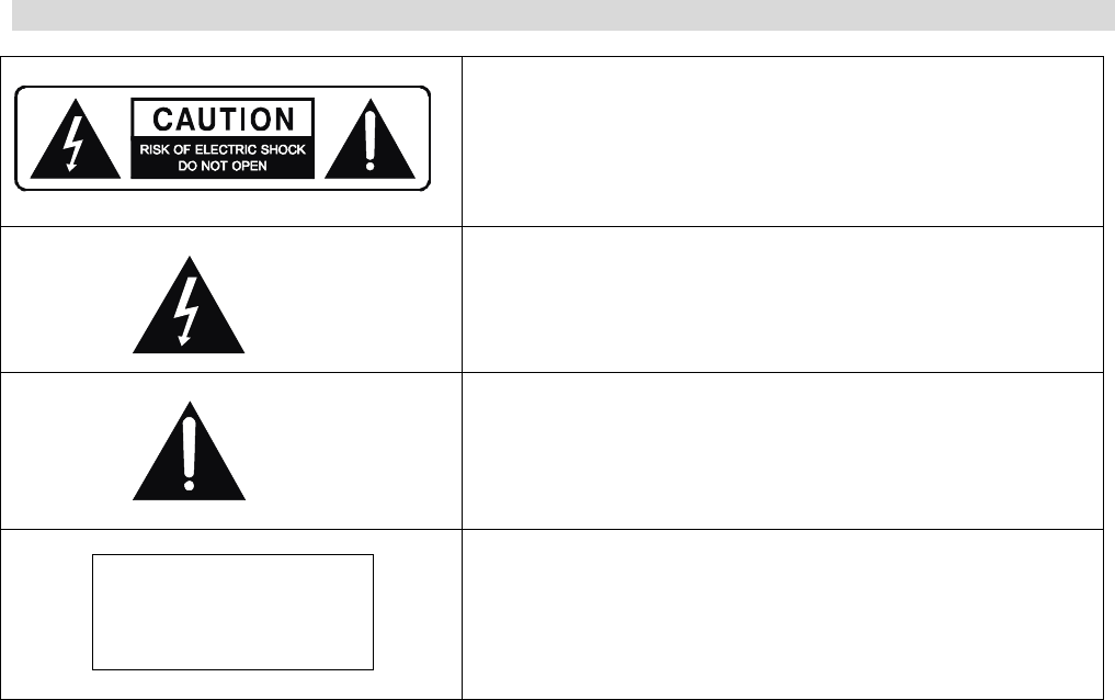
Caution:
- To reduce the risk of electric shock, do not remove Cover (or back)
- No user-serviceable parts inside.
- Refer servicing to qualified service personnel.
- Do not expose this appliance to rain or moisture
This lightning flash with arrowhead symbol, within an equilateral
triangle is intended to alert the user to the presence of uninstalled
“dangerous voltage” within the product’s enclosure that may be of
sufficient magnitude to constitute a risk of electric shock to persons.
The exclamation point within an equilateral triangle is intended to alert
the user to the presence of important operating and maintenance
(servicing) instructions in the literature accompanying the appliance.
CLASS 1
LASER PRODUCT
The marking of products using lasers (except for some areas). The
label is attached to the rear panel and says that the component uses
beams that have been classified as Class 1,which means the unit is
utilizing laser beams that are of weaker class. There is no danger of
hazardous radiation outside the unit
ACCESSORIES
1. RCA cord (yellow color).
2. Remote control.
3. Battery AAA x 2 for Remote control
4. Instruction Manual.
1

IMPORTANT SAFETY INSTRUCTIONS
CAUTION: READ THIS BEFORE OPERATING YOUR UNIT.
1. READ AND FOLLOW INSTRUCTIONS: All the safety and operation instructions should be read before
the product is operated. Follow all operation instructions within this manual.
2. RETAIN THESE INSTRUCTIONS: The safety and operation instructions should be retained for future
reference.
3. HEED WARNINGS: Comply with all warnings on the product and in the operation instructions.
4. CLEANING: Unplug this product from the wall outlet before cleaning. Do not use liquid cleaners or
aerosol cleaners. Use a damp cloth for cleaning.
5. GROUNDING OR POLARIZATION: This product may be equipped with a polarized alternating current
line plug (a plug having one pin wider than the other). This plug will fit into the power outlet only one way.
This is a safety feature. If you are unable to insert the plug fully into the outlet, try reversing the plug. If the
plug should still fail to fit, contact your electrician since it is likely you have an out of sate wall socket.
Never force the plug into the socket.
6. OVERLOADING: Do not overload wall outlets or extension cords as this can
result in the risk of fire or electric shock. Overloaded AC outlets, extension cords,
frayed power cables, damaged or cracked wire insulation, and broken plugs are
dangerous. They may result in electric shock or fire hazard. Periodically examine
the power cable - if its appearance indicates damage or deteriorated receptacles
have it replaced by your service technician.
7. POWER SOURCES: This product should be operated only from the type of power source indicated on
the rear panel label. If you are not sure of the type of power supply to your home, consult your product
dealer or local power company. For products intend to be operated from battery power, or other sources,
refer to the operation instructions.
8. ACCESSORIES: Do not place this product on an unstable surface or support. The
product may fall, causing serious injury to a child or adult as well as serious damage to
the product. Any mounting of the product should follow the manufacture’s instructions
and use a mounting accessory recommended by the manufacturer. A product and cart
combination should be moved with care. Quick stops, excessive force, and uneven
surfaces may cause the product and cart combination to overturn.
9. OUTDOOR ANTENNA GROUNDING: If an outside antenna or cable system is connected to the product,
be sure the antenna or cable system is grounded so as to provide some protection against voltage
surges and built-up static charges. The example below is for reference only. Correct grounding should
always be installed by an electrician.
A
NTENNA
LEAD IN
WIRE
A
NTENNA
DISCHARGE UNIT
(NEC SECTION 810-21)
GROUNDING CONDUCTORS
(NEC SECTION 810-21)
GROUND CLAMPS
POWER SERVICE GROUNDING
ELECTRODE SYSTEM
(NEC A RT 250 .PART H )
ELECTRIC
SERVICE
EQUIPMENT
GROUND
CLAMP
10. POWER CABLE PROTECTION: The power supply cables should be routed so that they are not likely to
be walked on or pinched by items placed upon or against them, paying particular attention to cables at
plugs and the point where they exit from the product.
11. ATTACHMENTS: Do not use unauthorized attachments as they may cause faults with the unit.
12. CONDITIONS REQUIREING SERVICE: Unplug this product from the wall outlet and refer servicing to
qualified service personnel under the following conditions:
a) If the unit exhibits sudden unusual operation or unusual display characteristics.
2
IMPORTANT SAFETY INSTRUCTIONS
b) If liquid has been spilled, or objects have fallen into the product.
c) If the product has been exposed to rain or water.
d) If the product does not operate normally by following the operation instructions, adjusting only those
controls that are covered by the operation instructions. (NOTE: improper adjustment of other
controls may result in damage and will often require extensive work by a qualified technician to
restore the product to its normal operation).
e) If the product has been dropped or damaged in any way.
f) If the product exhibits a distinct change in performance.
13. SERVICING: Do not attempt to service this product yourself as opening or removing covers may expose
you to dangerous voltage and may damage precision components. Refer all servicing to qualified
service personnel.
14. LIGHTNING: For added protection during a lightning storm, or when the unit is left unattended and
unused for long period of time, unplug it from the wall outlet and disconnect the antenna or cable system.
This will prevent damage to the product due to lightning and power line surges.
15. REPLACEMENT PARTS: Should replacement parts be required, have the service technician verify that
the replacement parts he uses have the same safety characteristics as the original parts. Use of
unauthorized replacements parts can cause fire or electric shock.
16. SAFETY CHECK: Upon completion of any service or repairs to this product, ask the service technician to
perform safety checks recommended by the manufacturer to determine that the product is in a safe
operating condition.
17. HEAT DISPERSAL: Leave at least 10 cm of space between the top, back and sides of the unit and the
wall or other electrical components.
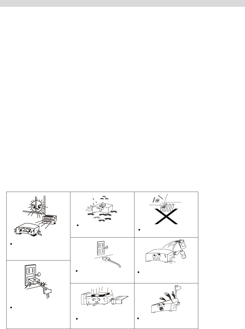
18. NOTES ON USE
Avoid high temperatures
Allow for sufficient heat dispersion
when installed on a rack.
Handle the power cord carefully.
Hold the plug when unplugging the
cord.
Keep the set free from moisture.
water,and dust.
Unplug the power cord when not
using the set for long periods of
time
Do not obstruct the ventilation
holes
* (For sets with ventilation holes)
Do not let foreign objects in the set.
Do not let insecticides,benzene,and
thinner come in contact with the set.
Never disassemble or modify the set
in any way.
3
BEFORE USE
Read this before operation
1. Choose the installation location of your unit
carefully. Avoid placing it in direct sunlight or
close to a source of heat. Also avoid locations
subject to vibrations and excessive dust, cold or
moisture.
2. Do not cover the ventilation holes. Make sure
there is enough space above and beside this unit
(about 4 inches). Do not place a CD player or
other equipment on top of this unit.
3. Do not open the cabinet as this might result in
damage to the circuitry or electrical shock. If a
foreign object falls into the unit, contact your
dealer.
4. When removing the power plug from the wall
outlet, always pull directly on the plug, never on
the cord.
5. Do not attempt to clean the unit with chemical
solvents as this might damage the finish. Use a
clean, damp cloth only.
6. Keep this manual in a safe place for future
reference.
Back-up Memory Function
This is the function that preserves the preset
memory and most-recent memory function. In the
event of a power failure, or if the power cord of this
unit is disconnected from the electric outlet, the
back-up memory will preserve the preset memory
and most-recent memory functions for approximately
1 week. If the power supply is interrupted for 7 days
or longer, the memory settings will be erased.
When to use RESET switch
1. When this system is subjected to an electric
shock.
2. When the power is irregular.
In this case, try the following:
Switch the POWER on, press the RESET button on
the front panel for more than 3 seconds.
Note: If the RESET button is pressed for more than
3 seconds, all the memory will be erased.
Before Connection
Caution
- Disconnect all equipment from the power source
before making any connections.
- Read instructions of each component you intend to
use with this unit.
- Be sure to insert each plug securely. To prevent
hum and noise, do not bundle the connection cords
with power cord or speaker cord.
Speaker Connections
Caution:
- To avoid damaging the speakers with a sudden
high-level signal, be sure to switch the power off
before connecting the speakers.
- Check the impedance of your speakers. Connect
speaker with an impedance of 6 ohms or more.
- The amplifier’s red speaker terminals are the +
(positive) terminals and the black terminals are the –
(negative) terminals.
- The + side of the speaker cable is marked to make
it distinguishable from the – side of the cable.
Connect this marked side to the red + terminals and
the unmarked side is the black terminal.
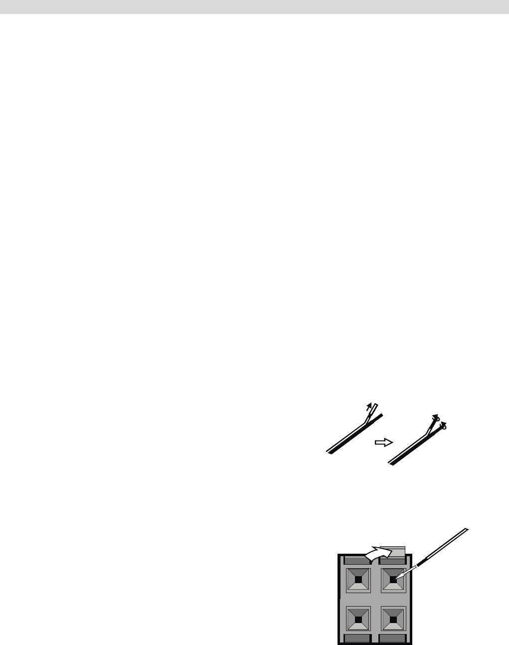
- Prepare the speaker cords for connection by
stripping off approximately 10 mm or less (no more
as this could cause a short-circuit) of the outer
insulation.
- Twist the wires tightly together so that they are not
straggly.
How to connect
Red: positive (+)
Black: negative (-)
1. Press down the lever at the antenna terminal.
2. Insert the exposed wire into the terminal hole
3. Release the lever.
4
CONNECTION
FM INDOOR ANTENNA
If you live reasonably close to a transmitter and want
to use the provided lead-type FM antenna, you will
have to connect it direct to the “FM 75” socket.
Fit the metal sleeve of the lead-type antenna over
the core (center) conductor of the (FM 75) socket,
extend the lead and fix it to a window frame or wall
with thumbtacks, or the like, where reception is best.
Lead-type FM 75 Antenna provided.
ANTENA
FM
75
Ω
AM
LOOP
Optional
A
NTENA
FM
75
Ω
A
M
LOOP
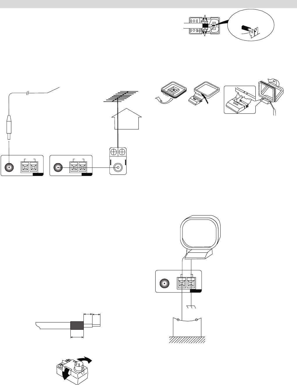
OUTDOOR FM ANTENNA (75)
FM OUTDOOR ANTENNA
In an area where FM signals are weak, it will be
necessary to use a 75 unbalanced-type outdoor FM
antenna using the optional matching transformer, as
shown. Generally, a 3-element antenna will be
sufficient: if you live in an area where the FM signals
are particularly weak, it may be necessary to use
one with 5 or more elements. Connect the coaxial
cable of the antenna to the matching transformer as
shown. After completing connection, plug the
transformer into the “FM 75” socket.
How to connect a coaxial cable to the matching
transformer
- Strip the cable and dress it as shown.
4mm 3mm
7mm
- Press both side tabs outward to remove the cover.
- Wrap the core conductor around the central metal
fixture as shown.
- Crimp the jagged metal fixtures so they hold the
braided portion using pliers, etc.
- Put the cover back in place.
Jagged metal
Jagged metal
Insert into slit.
AM INDOOR LOOP ANTENNA
- To stand the antenna on a flat surface, fix the claw
to the slot.
123
- The high performance AM loop antenna provided
with this unit is sufficient for good reception in most
areas.
- Connect the loop antenna’s wires to the AM
antenna terminals as shown.
- Place the antenna on a shelf or hang it on a window
frame, etc, in the direction which gives the best
reception and as far away as possible from the entire
system, speaker cords and the power cords, to
prevent unwanted noise.
AM Loop Antenna (provided)
A
NTENA
FM
75
Ω
A
M
LOOP
AM Outdoor
Antenna
AM Outdoor Antenna
If the AM loop antenna provided does not deliver
sufficient reception (because you are too far from the
transmitter or in a concrete building, etc.), it may be
necessary to use an outdoor AM antenna.
Use an insulated wire more than 15 ft (5m) long, strip
one end, and connect this to the terminal as shown.
The antenna wire should be strung outdoors or
indoors near a window. For better reception, connect
the GND terminal to a reliable ground.
Note: When connecting an outdoor AM antenna, do
not disconnect the AM loop antenna.
5
CONNECTION
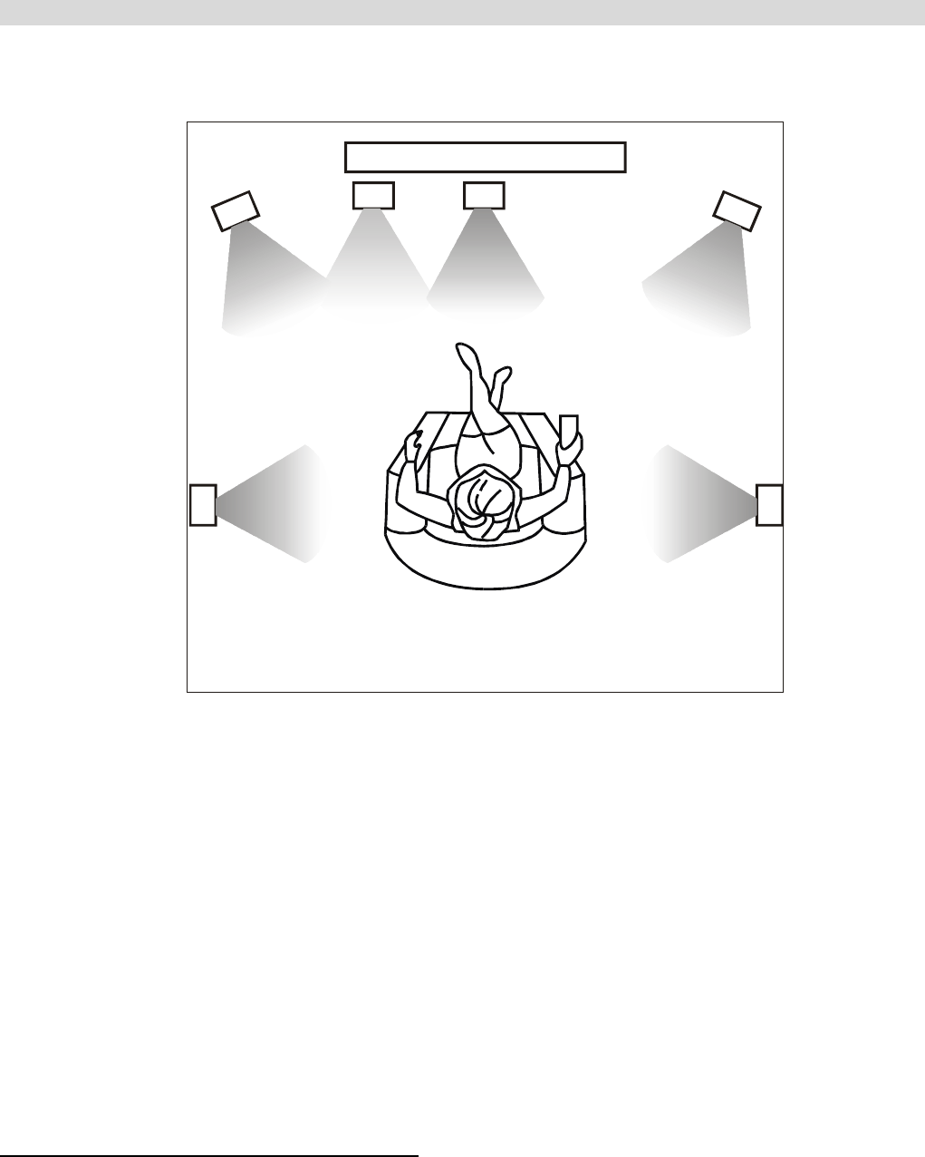
Speaker layout example when using surround mode
1
2345
67
8
1. TV or Screen 2. Front Left Speaker 3. Subwoofer
4. Center Speaker 5. Front Right Speaker 6. Surround Left Speaker
7. Surround Right Speaker 8. Listening Position
Standard speaker setup for surround sound
● Front Right and Left speakers
These are the main speakers providing the front stereo effect of the sound image.
● Centre speaker
This produces a rich sound image by serving as a centre sound source for the front right and left speakers
thus enhancing the sonic movement.
● Surround Right and Left speakers
These add three-dimensional sonic movement and produce environmental sound associated with the
background and effect sounds for each scene.
● Subwoofer
Required to add powerful and heavy bass.
Speaker placement
Ideal speaker placement varies depending on the size, shape of your room and the wall coverings. Here is a
typical example of speaker placement and recommendations as shown.
Important points regarding speaker placement
Front Right and Left speakers and Centre speaker
- Place these three speakers all at the same height.
- Place each speaker so that it is aimed at the location of the listener’s ears when at the listening position.
- Try to place all the front speakers at the same distance from the listening position.
Surround Left and Right speakers
- Place these speakers so that their height is 3 feet (1 meter) higher than that of the listener’s ears.
Subwoofer
Ideally a subwoofer should always be located in front of the listening position between the Front Left and Right
speakers. Since all rooms vary, experiment with the placement of your subwoofer for the best overall sound
image (placing a subwoofer in the corner of a room often helps to disperse the sound).
6
CONNECTION
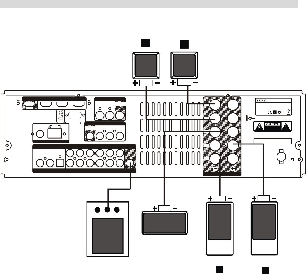
SPEAKER CONNECTION
R
L
R
L
CENTER
FRONT
FRONT
SUBWOOFER
SURROUND BACK
Manufactured under license from Dolb
y
Laboratories.
Dolby , Pro Logic , and the double-D symbol
are trademarks of Dolby Laboratories.
“”“ ”
Manufactured under license from Di
g
ital Theater S
y
stems, Inc.
U.S. Pat.No s. 5,451,942, 5,956,674, 5,974,380, 5,978,762, 6,487,535 and ot her
U.S. and world-wide patents issued and pending.
"DTS" are trademarks of Digital Theater Systems, Inc.
Copyright 1996,2003 Digital Theater Systems, Inc. All Rights Reserved.
’
RISK OF ELECTRIC SHOCK
DO NOT OPEN
S-VIDEO
DVD
IN AV 1
IN
MONITOR
OUT AV 1
IN AV 2
IN DVD
IN
VIDEO
MONITOR
OUT
COAXIAL OPTICAL SUB
DIGITAL INPUT ANALOG INPUT PRE OUT
DVDAV 2AV 1AUXOUT TAPE IN
DVDAV 2AV 1 L
R
RS
LS
C
FR
FL
A
C 220-240V
50Hz
SERIAL NO.
GND
HDMI
OUT AV2 IN AV1 IN DVD IN
AM
LOOP
ANTENNA
FM
75
ٛ
SPERKERS 6-8
ٛ
MODEL NO: AG20D
POWER SOURCE: 220V-240V~50Hz
POWER CONSUMPTION: 300W
R
N533
RS232C
Power cord (AC)
- Be sure to connect the power cord to an AC outlet, which supplies the correct voltage.
- Hold the power plug when plugging or unplugging the power cord.
- When connecting this AV receiver up to your TV, or other components, make sure that all components are
switched off and unplugged from main AC power.
Subwoofer Out
Use this jack to connect an active subwoofer.
7
CONNECTION
AM
LOOP
FM
75
ٛ
DVD
IN
V
IDEO 1
IN MONIT OR
OUT
MONIT OR
OUT VIDEO 1
IN
V
IDEO 2
IN DVD IN
TAPE
OUT TAPE
IN AUX VIDEO 1
V
IDEO 2 DVD
COAXIAL OPTICAL
DVD
R
L
ANTENNA
DVD, VCD
S-VIDEO OUT VIDEO OUT
MONITOR(TV)
S-VIDEO
IN
VIDEO
IN
CDR/W
COAX OUT
S-VIDEO
VIDEO
DIGITAL INPUT
VIDEO 1 VIDEO 2
HDMI
OUT AV2 IN AV1 IN DV D I N
DVD
IN
HDMI OUT
RS232C
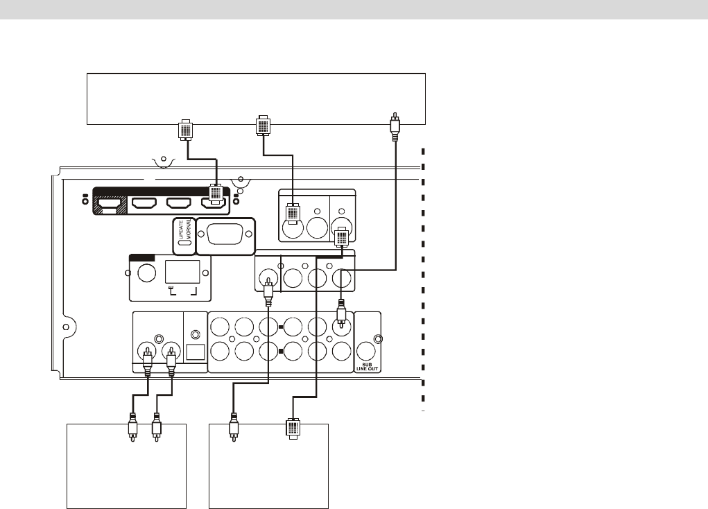
When connecting video components such as DVD
players, cable boxes, satellite receivers and
television/plasmas, you can use different types of
cables depending on how the video component is
equipped.
Video connections:
If the video component is equipped with S-VIDEO
jacks, it is recommended to connect to your unit or
directly to the television monitor using an S-VIDEO
cable. S-VIDEO cables provide better picture clarity
and resolution. If the video component is not
equipped with an S-VIDEO jack, use a conventional
RCA or RCA composite cable to connect to your unit
or connect it directly to the television. The illustration
here shows how to connect video components to
your unit.
Note:
When connecting more than one video component to
your unit (i.e. VCR and DVD player) it is easier to
use either all S-VIDEO cables or all RCA to RCA
composite cables. This allows both video signals
(DVD and VCR) to be sent through your unit to the
TV monitor using just one video input on the TV
(S-Video or RCA). Regardless of the video
component being played DVD or VCR, the picture
will always appear on the same video input of the
monitor.
If you use both S-Video and RCA composite cables
to connect different video components to your unit,
you must also use both S-Video and RCA composite
cables to connect the TV monitor to your unit. For
example, if you connect a DVD player to your unit
using S-Video cable and a VCR using an RCA to
RCA composite cable, you must also connect the TV
to your unit using both types of cables. This requires
an S-Video cable from the S-Video monitor out jack
on your unit to an S-Video input on the TV (i.e. Video
1). In addition, you must use an RCA composite
cable from the composite video monitor out jack on
your unit to an RCA composite video input on the TV
but not the same input used for the S-Video cable
(i.e. Video 2). Using this type of dual cable video
connection, you will need to switch the TV video
input source from TV to Video 1 to Video 2
depending on the video source being played-TV,
DVD or VCR.
8

CONNECTION
Audio connections:
Some video components are equipped with special
digital audio outputs (e.g. DVD players). If your video
component is equipped with a digital audio output, it
is recommended that you connect to your unit using
a digital cable. Digital audio cables are required to
use the DTS and Dolby Digital surround sound
modes. If you do not use digital connections, your
unit will only operate in Dolby PRO LOGICII, MUSIC,
THEATER, HALL and 5 Stereo surround modes.
There are two types of digital cables-coaxial (75 ohm)
and optical. Your unit is equipped with both types of
digital inputs. These inputs are labelled COAXIAL IN
and OPTICAL IN on the rear of the unit. Connect the
video component outputs to any one of the two
digital inputs on your unit. If the video component is
not equipped with a digital output, use a dual RCA to
RCA composite audio cable to connect to your unit.
Make sure to connect:
White plug to white jack (L: left)
Red plug to red jack (R: right)
Note:
When an optical cable is used, remove the
protection caps from the component and your unit
before attempting to insert the optical cable. If not
using an optical cable or if the cable is removed,
always re-install the protection caps to prevent dirt
and dust from entering the inputs. If using a coaxial
digital cable, leave the protection caps in both the
video component and your unit.
CD, TAPE jacks
Connect the component with RCA to RCA cords.
Make sure to connect:
White plug to white jack (L: left)
Red plug to red jack (R: right)
DIGITAL IN/OUT terminals
If the CD player or MD player has digital outputs,
connect the component with coaxial cables or optical
cables.
DIGITAL IN to DIGITAL OUT (CD, etc.)
DIGITAL OUT to DIGITAL IN (MD, etc.)
Connect to any one of the DIGITAL IN terminals.
When using DIGITAL OPTICAL IN terminals, remove
the caps from the terminals. When you do not use
them, leave the caps in place. To record digitally,
connect the source (CD player, etc.) to DIGITAL IN
and the recorder (MD, etc.) to DIGITAL OUT.
9
REMOTE CONTROL UNIT
By using the provided remote control unit, this unit
can be controlled from your listening position. To use
the remote control unit, point it at the REMOTE
SENSOR window of this unit.
Notes:
- Even if the remote control unit is operated within
the effective range, remote control operation may be
impossible if there are any obstacles between the
unit and the remote control.
- If the remote control unit is operated near other
appliance which generate infrared rays, or if other
remote control devices using infrared rays are used
near the unit, it may operate incorrectly.
- The power is turned on/off (standby) by pressing
the POWER button on the remote control unit in
standby mode.
Precautions concerning batteries
- Be sure to insert the batteries with correct positive+
and negative – polarities.
- Use batteries of the same type. Never use different
types of batteries together.
- Rechargeable and non-rechargeable batteries can
be used. Refer to the precautions on their labels.
- When the remote control unit is not to be used for a
long time (more than a month), remove the batteries
from the remote control unit to prevent them from
leaking. If they leak, wipe away the liquid inside the
battery compartment and replace the batteries with
new ones.
- Do not heat or disassemble batteries and never
dispose of old batteries by throwing them in a fire.
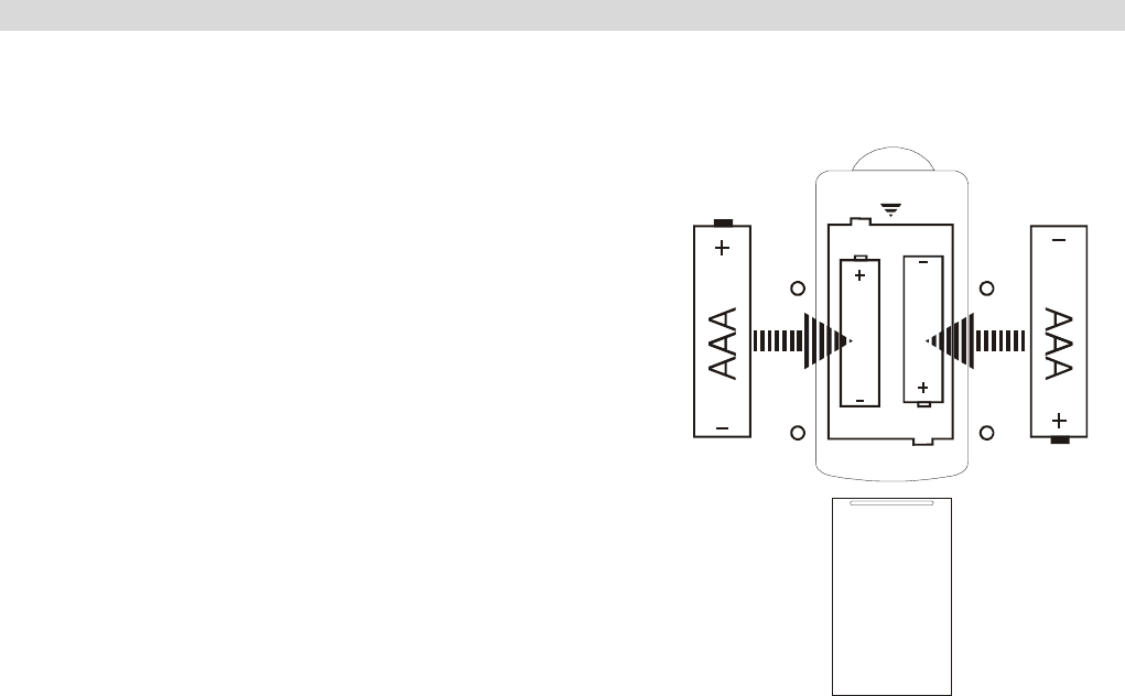
BATTERY INSTALLATION
1. Remove the battery compartment cover.
2. Insert two “AAA” dry batteries. Make sure that
the batteries are inserted with their positive “+”
and negative “-” poles positioned correctly.
3. Close the cover until it clicks.
If the distance required between the remote
control unit and main unit decreases, the
batteries are exhausted. In this case, replace the
batteries with new ones.
10
FRONT PANEL INFORMATION
POWER
PHONES TAPE AUX TUNER
/BAND VIDEO 2 VIDEO 1 DVD DTS/DOLBY
DIGITAL 2CH DIGITAL
IN SURROUND
MODE SUB
ON/OFF
STEREO STATION
VOLUME
R
RESET
AG20D 5.1 CHANNEL HOME THEATRE RECEIVER
1
2 3 56
8 9 10 1211 13 14 15 16 1917 18 20 21
APS
47
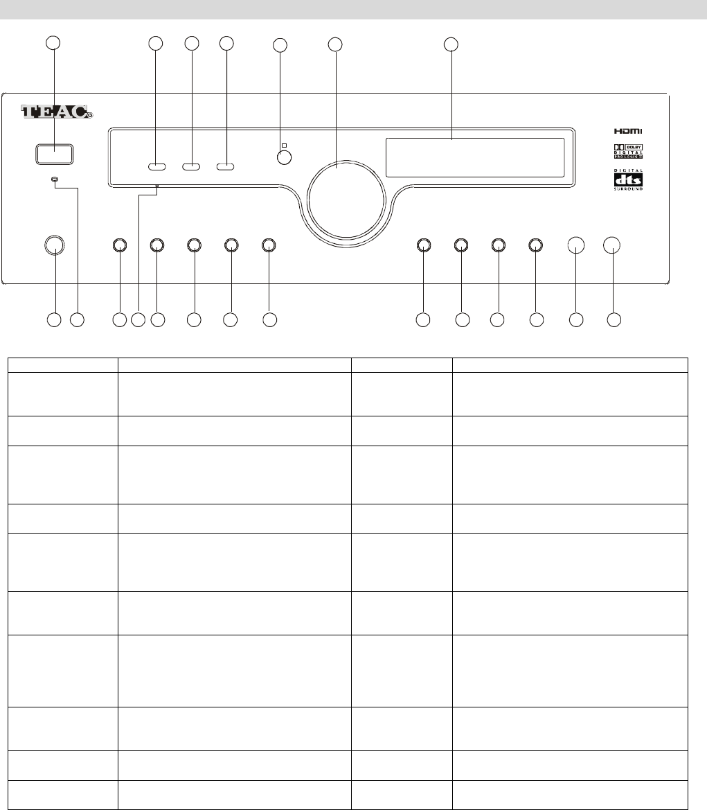
1. POWER Turns the unit on/off. 12. AUX Press this button to select AUX.
2. STEREO Press this button to alternate between
Stereo and Mono mode when listen
to FM broadcast.
13.
TUNER/BAND
Press this button to select the TUNER.
Press again to select FM and AM.
3. STATION When using the Tuner press this button
to select a preset channel.
14. VIDEO 2 Press this button to select VIDEO 2.
4. APS Allocates and memorizes radio stations
automatically. (Note: Hold this button
down for more than 3 seconds to
activate
15. VIDEO 1 Press this button to select VIDEO 1.
5. REMOTE
SENSOR
16. DVD Press this button to select DVD.
6. VOLUME To decrease or increase the Master
Volume.
17.
DTS/DOLBY
DIGITAL
When playing 5.1CH source, and while
you are enjoying Stereo, press this
button to playback source in
DTS/DOLBY DIGITAL.
7. VFD DISPLAY
UNIT
Informs you of selected inputs and
system state.
18. 2CH Select STEREO mode (Note: only
Front Left & Front Right and Woofer
speakers are activated).
8. PHONES Jack for stereo headphones. 19. DIGITAL IN Press this button when using a source
connected by a DIGITAL IN. Press it to
select : DVD COA. DVD OPT, VIDEO 1
OPT and VIDEO 2 OPT, or when using
an analog source.
9. STANDBY
INDICATOR
20.
SURROUND
MODE
Select surround modes: MOVIE and
MUSIC.
10. TAPE Press this button to select TAPE. 21. SUB
ON/OFF
Press this button to turn on/off the
subwoofer.
11. RESET To reset the whole system to factory
defaults.
11
REAR PANEL INFORMATION
54321
711910
Manufactured under license from Dolb
y
Laboratories.
Dolby , Pro Logic , and th e double-D symbol
are trademarks of Dolby Laboratories.
“”“ ”
Manufactured under license from Di
g
ital Theater S
y
stems, Inc.
U.S. Pat.No s. 5,451,942, 5,956,674, 5,974,380, 5,978,762, 6,487,535 and other
U.S. and world-wide patents issued and pending.
"DTS" are trademarks of Digital Theater Systems, Inc.
Copyright 1996,2003 Digital Theater Systems, Inc. A ll Rights Reserved.
’
RIS K OF ELEC TRIC SHO CK
DO NOT OPEN
S-VIDEO
DVD
IN AV 1
IN
MONITOR
OUT AV 1
IN AV 2
IN DVD
IN
VIDEO
MONITOR
OUT
COAXIAL OPTICAL SUB
DIGITAL INPUT ANALOG INPUT PRE OUT
DVDAV 2AV 1AUXOUT TAPE IN
DVDAV 2AV 1 L
R
RS
LS
C
FR
FL
A
C 220-240V
50Hz
SERIAL NO.
GND
HDMI
OUT AV2 I N AV1 IN D VD IN
AM
LOOP
ANTENNA
FM
75
ٛ
SPERKERS 6-8
ٛ
6
MODEL NO: AG20D
POWER SOURCE: 220V-240V~50Hz
POWER CONSUMPTION: 300W
R
N533
RS232C
8
HDMI
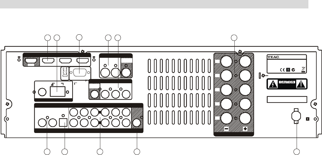
1. COAX. IN
Digital audio input for connection to the digital output of another DVD/Decoder/Games Console.
2. DIGITAL INPUT
Optical audio input for connection to the optical output of another DVD/Decoder/Games Console.
3. ANALOGUE AUDIO IN/OUT terminals
4. SUB LINE OUT
Pre-out for an active subwoofer.
5. AC CORD
Connect to the AC mains socket.
6. HDMI PORT
For connection to the equipment with HDMI output.
7. ANTENNA terminal
Connect to the AM indoor loop antenna/Lead-type FM antenna.
8.RS232 port
9.S-VIDEO IN/OUT terminals
- DVD S-VIDEO IN: Connect an S-VIDEO cable to the S-VIDEO output terminal of a DVD player.
- VIDEO-S IN: For connection of S-VIDEO cable to the output terminal of an external player.
- VIDEO-S OUT: For connection of S-VIDEO cable to the input terminal of an external player.
10.VIDEO IN/OUT terminals:
- VIDEO OUT: Use an RCA composite cable to connect to the TV set.
- V1/V2 IN: Connect RCA composite cables to the line outputs of external players.
- DVD IN: Using an RCA composite cable to the line output of a DVD.
11.SPEAKERS
External speakers power output. (Refer to Speaker Connection section)
12
REMOTE CONTROL INFORMATION
BASS
MEMORY
TREBLE
DIMMER
VOL
SUBWOOFER
ON/OFF
TUNING
BASS
MODE
MUTE
POWER
INPUT MODE
LFE TRIM
TEST
TONE
DELAY TIME
TUNER
VIDEO 1
AUX
VIDEO 2
TAPE
DVD
APS
BANDMANUAL
ST/MONO
SURROUND
MODE
CH
SELECT
DTS/DOLBY
DIGITAL
VOL PRESET +
PRESET
AG20D
R
13

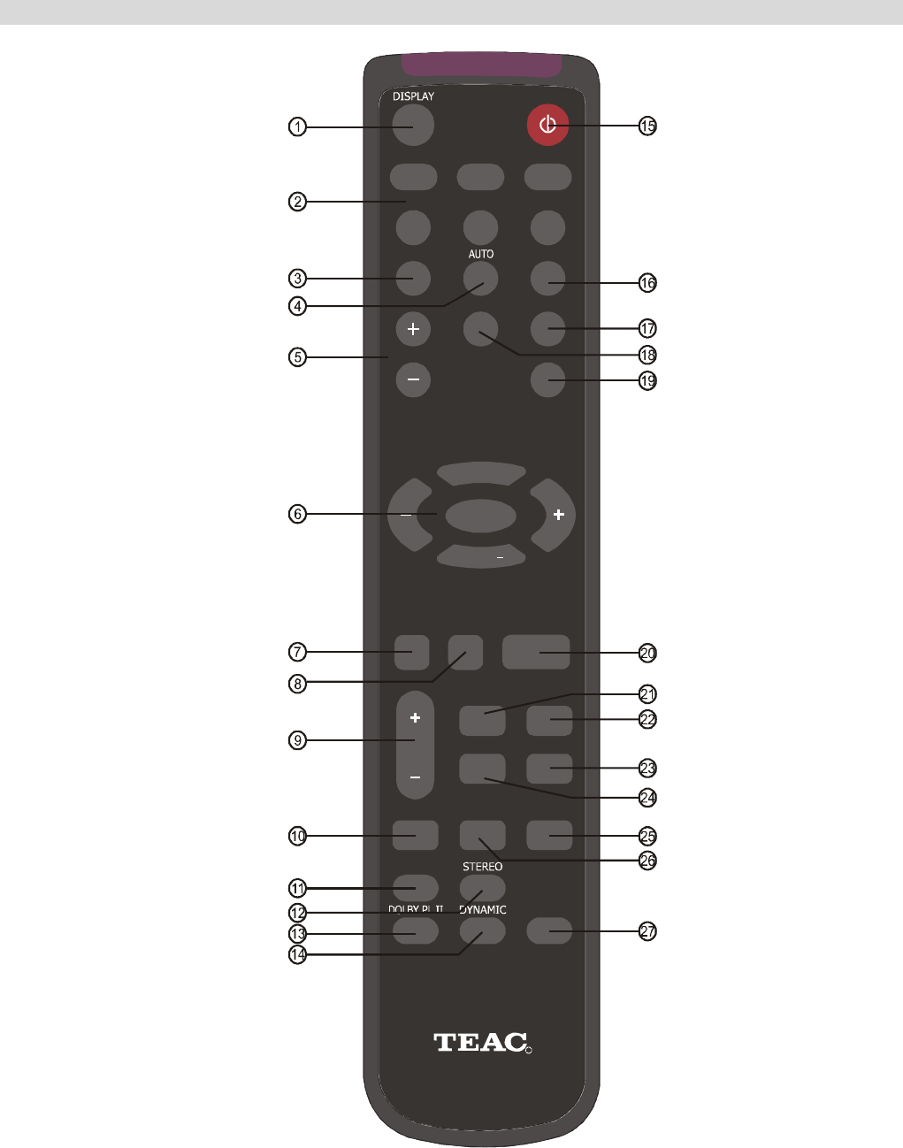
REMOTE CONTROL INFORMATION
1. Display
Press this button to display the state of input source. And when listening to the FM broadcasting with RDS,
press this button to show PS, PTY, RT and RT.
2. Input Source
Choose the input as your desire, you can chosse DVD VIDEO1 VIDEO2 TUNER AUX and TAPE
3. Memory: Press it to store the broadcast station as a preset.
4. Auto
This button is used to select AUTO tuning for AM and FM stations.
5. Tuning +/-
Tuner frequency up and down..
6. Cursor
- Vol +/-: decrease or increase the volume.
- Preset +/-: Press these buttons to select a preset channel during the tuner mode.
- Mute: Press this button to mute the sound, push again to cancel the mute function.
7. Dimmer
Press this button to set the brightness of the front panel display.
8. CH Select
Select channels by pushing this button, then use volume key to balance speakers.
9. +/-
These keys are used for SPK SETUP and DELAY TIME, Treble and Bass adjustment.
10. Delay Time
Press this button to set the delay time for the Dolby digital/Dolby Pro Logic modes.
11. Surround Mode
Select surround modes: MOVIE and MUSIC.
12. Stereo
With the unit in the STEREO mode, only front left and front right speakers and Woofer are working.
13. Dolby PL II
When receiving Analog/digital PCM signal or 2CH Pro Logic, turn on this button then the playing is under
analog 5.1CH state.
14. Dynamic
Press this button repeatedly to reach your desired compression dynamic range.
15. Power
Push this button to turn the unit into standby mode, push it again to turn off the unit.
16. ST/Mono
Press this button to alternate between Stereo and Mono mode when listen to FM broadcast.
17. Band
Press this button to alternate between FM and AM.
18. Manual
This button is used to select MANUAL tuning for AM and FM stations.
19. APS
Allocates and memorizes radio stations automatically. (Note: Hold this button down for more than 3 seconds to
activate
20. SUB Woofer On/Off: Push this button to turn on or off the subwoofer output.
21. Bass
Press this button for Bass adjustment, then press +/- key to adjust the level.
22. LFE Trim
Under the Pro Logic 5.1CH or DTS 5.1CH mode, press this button and adjust the volume to set the Low
Frequency output level
23. Input Mode
Select Coaxial, Optical or Analog Input mode in DVD, AV1 and AV2.
24. Treble
Press this button for Treble adjustment, then press +/- key to adjust the level.
25. Test Tone
To balance speakers in Dolby Digital or Dolby Pro Logic mode.
26. Bass Mode
Press this button to set the delay time for the Dolby digital/Dolby Pro Logic modes.
Select one of the two preset speaker configuration according to your speakers. (refer to page 17)
27. DTS/Dolby Digital
When playing 5.1CH source, and while you are enjoying Stereo, push this button to playback source in
DTS/DOLBY DIGITAL.
14

BASIC OPERATION
BASIC OPERATION 1
1. Press the POWER button to put this unit into Standby Mode.
2. Press one of the source buttons to activate the unit.
3. Select the desired source by pressing DVD, VIDEO 1, VIDEO 2, TUNER, AUX or TAPE.
If you have selected DVD, VIDEO 1, VIDEO 2 (not TUNER, AUX or TAPE), press INPUT MODE,
SURROUND MODE, DTS/DOLBY DIGITAL, STEREO, DOLBY PROLOGIC II or DIGITAL IN in
accordance with the type of signal you are receiving and the sound output you require (for example, Dolby
Pro Logic II if the DVD movie is an older "classic" and only recorded in stereo).
4. Play the source, and gradually turn up the volume to the required level with the VOLUME control.
BASIC OPERATION 2
A. POWER button
Press this button to turn this unit into standby mode, then the STANDBY indicator lights up, press one of the
source buttons to activate this unit, the standby indicator goes out when this unit is turned on.
B. SURROUND MODE
This mode is used to achieve a realistic sound field with a “three-dimension”, giving the sense of distance,
movement and relative position, creating a real and powerful sense of presence.
C. STEREO
In the STEREO mode, only the Front Left and Front Right speakers and Subwoofer are activated.
D. DOLBY PRO LOGIC II
Pro Logic II uses a directional emphasis circuit to decode five output channels (Front Left & Front Right, Centre
and Surround) from a stereo audio channel.
E. DTS/DOLBY DIGITAL
When playing 5.1CH source, and while you are enjoying Stereo, press this button to playback source in
DTS/DOLBY DIGITAL.
F. PHONES jack
For private listening, insert your headphones (1/4 –inch plug) into the PHONES jack. The centre and surround
speakers will be cut automatically.
Note: When using headphone, the audio output will automatically down mix to STEREO.
15

BASIC OPERATION
PLAYING VIDEO SOURCES
1. Select DVD, VIDEO1, VIDEO 2 by pressing the corresponding button.
2. Play the sound source corresponding to the source selected (for example, if you have selected DVD, press
PLAY on your DVD player).
3. The picture from the video source will be transmitted to the TV and the sound from the video source will be
heard from the speakers.
THE RADIO OPERATIONS
Automatic Tuning
1. Press the POWER button, then press the TUNER button to turn ON this unit.
2. Select TUNER mode by pressing the TUNER button.
3. Select the appropriate frequency band (FM or MW) by pressing the TUNER button again.
3. Press the AUTO/MANUAL button on the remote to activate automatic selection. (Note: default mode is
Manual selection) "Auto" now appears on the display.
4. Press the TUNING +/- on the remote to select the station you want to listen to. When a station is tuned in,
the tuning process will stop automatically. (Automatic station selection)
5. Press TUNING +/- on the remote again to select another channel.
MANUAL TUNING
Use this function for selecting stations which cannot be tuned automatically due to a weak signal
To tune a channel manually:
Skip step 4 in the above procedures. Each time the TUNING +/- button is pressed momentarily (0.5 second or
less), the frequency changes by a fixed increment (FM: 50 kHz increments, MW: 9 kHz increments).
FM Modes Available:
Press the STEREO button to alternate between Stereo mode and Mono mode.
Stereo: FM stereo broadcasts are received in stereo and the “∞” indicator lights on the display.
Mono: Use to compensate for weak FM stereo reception. Reception will now be forced to monaural, reducing
unwanted noise.
PRESET TUNING
This facility is used to store FM and MW stations from channels 1 to 15 respectively.
Automatic Memory Presetting:
1. Select TUNER mode by pressing the TUNER button.
2. Select MW or FM by pressing the TUNER button again.
3. Press the APS button.
The 15 best-reception stations in your area will be automatically stored.
Manual Memory Presetting
1. Select TUNER mode by pressing the TUNER button.
2. Select MW or FM by pressing the TUNER button again.
3. Press the TUNING +/- button on the remote to select a station you want to preset.
4. Press the MEMORY on the remote button briefly.
5. While the “MEM” indicator is lit, press TUNING +/- button to select a preset station. The station number will
be displayed on the screen.
6. Press the MEMORY button again.
To store more stations, repeat steps 3 to 6.
How to select preset stations
Ensure you are in TUNER mode and press the STATION button to select a preset radio station.
16
SPEAKER CONFIGURATION, DELAY TIME & DYNAMIC RANGE CONTROL
SPEAKER CONFIGURATION
It is important to configure your speakers correctly in
order to get the most from your AV Receiver. This
versatile AV Receiver provides the flexibility to
experience multi-channel surround sound without a
center speaker. However, for best results with Dolby
Pro Logic II, DTS and Dolby Digital decoding, at
least 5 speakers (Left, Center, Right, Left Rear and
Right Rear) should be used. (Note: As with all
surround sound configurations, we recommend the
use of a Subwoofer speaker to fully experience the
Low Frequency Effect encoded into most of today's
DVD movies).
BASS MODE
There are 2 preset speaker configurations based on
the size of your speakers.
Default is Mode 1.
Front L
& R
Center Rear L
& R
Sub-Woofer
Mode1 Small Small Small On
Mode2 Large Small Small On
Press BASS MODE to select one of the 2 modes
according to your speaker's size.
(Note: Large speakers can fully reproduce low
frequencies of below 80Hz. Small speaker cannot
reproduce low frequencies of below 80Hz with
sufficient volume. Refer to your speaker
specifications to select the correct size).
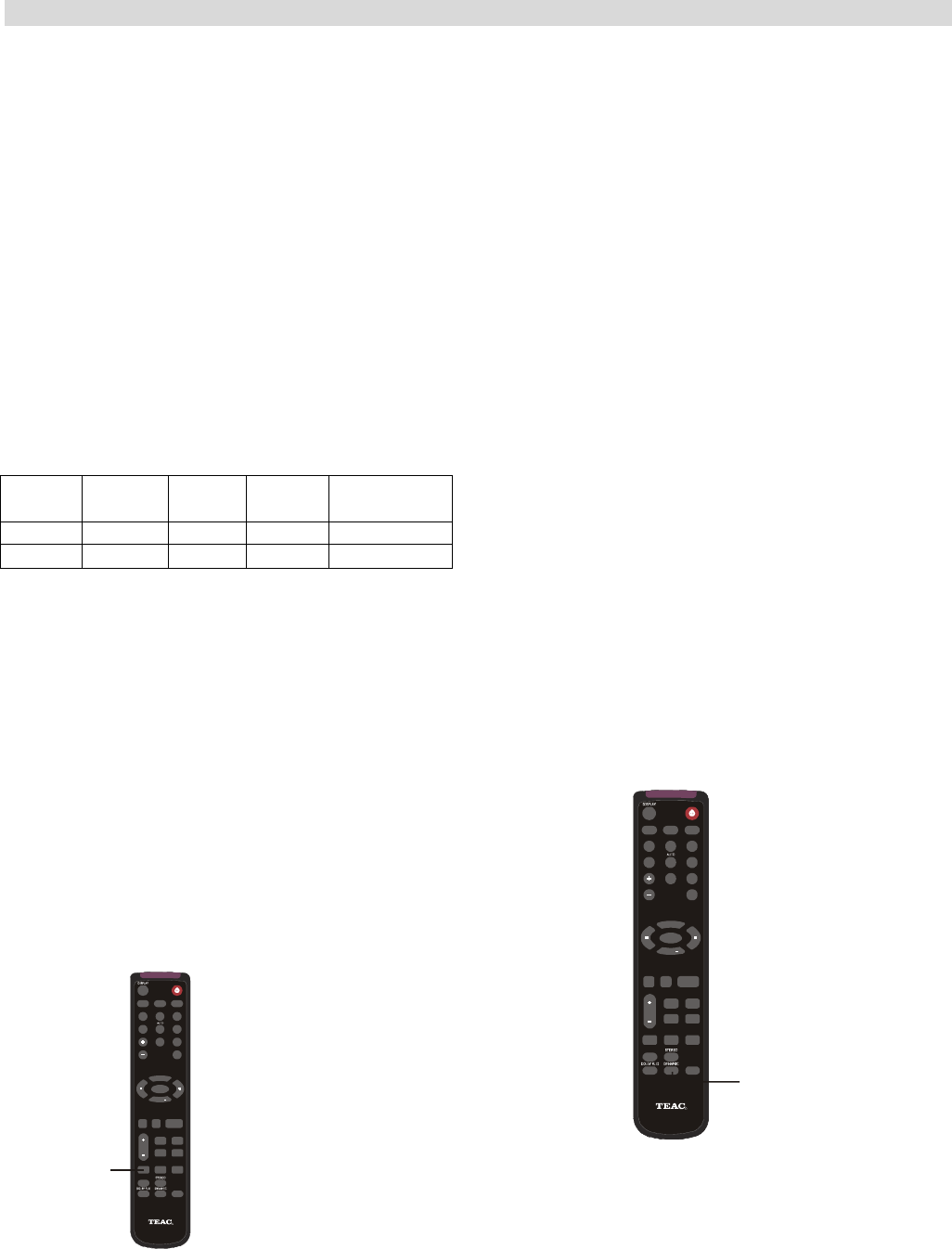
DELAY TIME
The delay time can be individually set for the Dolby
Digital/Dolby Pro Logic II modes using the DELAY
(CENTER/REAR) buttons.
When you adjust the delay time in the Dolby Digital
mode, an additional 15 ms is automatically added to
the surround channels in the Dolby Pro Logic mode.
The current setting is shown on the display.
DELAY
TIME
BASS
MEMORY
TREBL E
DIMMER
VOL
SUBWOOFER
ON/OFF
TUNING
BASS
MODE
MUTE
POWER
INPUT MODE
LFE TRIM
TEST
TONE
DELAY TIME
TUNER
VIDE O 1
AUX
VIDE O 2
TAPE
DVD
APS
BANDMANUAL
ST/MONO
SURROUND
MODE
CH
SELECT
DTS/DOLBY
DIGITAL
VOL PRESET +
PRESET
A
G20D
R
1. Press "DELAY TIME" on the remote control
repeatedly, the corresponding speaker appears on
the display: S → C
2. Press +/- button to set the time delay.
Delay Time Setting Adjustable Range
DOLBY DIGITAL MODES:
0-15 ms in 5 ms step (S-Delay)
0-5 ms in 1 ms step (C-Delay)
DOLBY PRO LOGIC II MODE:
10-25 ms in 5 ms step (S-Delay)
In the surround modes, the sound from the speakers
should be delayed slightly, relative to that from the
front speakers.
The optimum delay time will depend on acoustic
properties, whether the walls and furnishings reflect
or absorb sound, etc.
It is recommended that you try different delay times
to obtain the best effect. The delay is digitally
synthesized.
For the highest sound quality with minimum noise
and distortion, the delay time can be set
independently for each surround mode using the
DELAY TIME buttons, with the current setting shown
in the display.
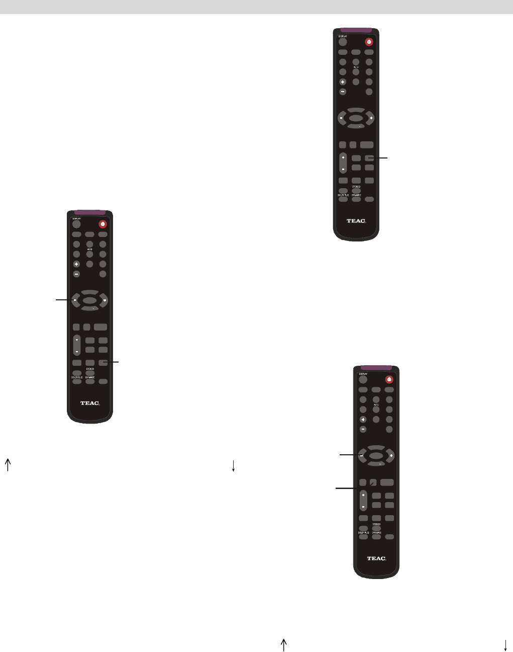
DYNAMIC RANGE CONTROL
This button controls the compression range of sound
track. If the compression is large (DRC = 4/4), the
sound effect is retarded to a certain range. As a
result, sound effect is not as excited as normal range
DRC = 0/4). It is useful when you want to movies at
the late night.
Press DYNAMIC on remote control repeatedly
until the desired compression range reached.
DYNAMIC
BASS
MEMORY
T
REBLE
DIMMER
VOL
SUBWOOFER
ON/OFF
TUNING
BASS
MODE
MUTE
POWER
INPUT MODE
LFE TRIM
TEST
TONEDELAY TIME
TUNER
VIDEO 1
AUX
VID EO 2
TAPE
DVD
APS
BANDMANUAL
ST/MONO
SURROUND
MODE
CH
SELECT
DTS/DOLBY
DIGITAL
VOL PRESET +
PRESET
AG20D
R
DRC=0/4 No Compression
DRC=1/4
DRC=2/4
DRC=3/4
DRC=4/4 Greatest Compression
Note:
1. The Dynamic Range Control state will resume to
normal if you do not press it after 5 seconds.
2. Dynamic Range Compression is not possible with
DTS sources.
17
TEST TONE, LFE TRIMMER & CHANNEL SELECT
TEST TONE
Speaker Level balance Adjustment
The test tone function is useful to adjust the relative
volume between speakers in DOLBY DIGITAL or
DOLBY PRO LOGIC II mode.
Once the balance is set, you don’t have to change the
balance as long as the speakers aren’t moved.
1. Adjust the MASTER VOLUME to the normal
listening level. (Half of max. Volume is recommended)
2. Press the TEST TONE button (on the remote
control) in DTS, Dolby Digital or Dolby PRO LOGIC II
mode.
The test tone is emitted from each speaker each time
you press “TEST TONE”.
TEST
TONE
VOLUME
BASS
MEMORY
T
REBLE
DIMMER
VOL
SUBWOOFER
ON/OFF
TUNING
BASS
MODE
MUTE
POWER
INPU T MO DE
LFE TRIM
TEST
TONE
DELAY TIME
TUNER
VIDEO 1
AUX
VIDEO 2
TAPE
DVD
APS
BANDMANUAL
ST/MONO
SURROUND
MODE
CH
SELECT
DTS/DOLBY
DIGITAL
VOL PRESET +
PRESET
A
G20D
R
→L(FRONTLEFT)→R(FRONTRIGHT)→LS (SUR. LEFT)
← SUB ← C (CENTER) ← RS (SUR. RIGHT)
3. Select a speaker by pressing the “TEST TONE”
button and adjust the level by pressing the MASTER
VOLUME button.
The level of each speaker can be adjusted in 1 dB
step from –10 dB to +10 dB.
4. When the setting is finished, press the TEST TONE
button to stop the test tone. (Note: You must keep
press TEST TONE until one complete cycle is
finished.)
LOW FREQUENCY EFFECT
LFE (LOW FREQUENCY EFFECT) MIX LEVEL
(LFE MIX) initial setting: 0 dB
Under COAX./OPT mode, when playing a Dolby
Digital or DTS 5.1CH signal, LFE will appear on the
display. Press the LFE key on the remote and press
the VOL +/- button to adjust the level between 0dB
to –10dB. (Note: The LFE adjustment function will
resume to normal, if the VOL +/- button is not pressed
within 5 seconds.)
LFE TRIM
BASS
MEMORY
T
REBLE
DIMMER
VOL
SUBWOOFER
ON/OFF
TUNING
BASS
MODE
MUTE
POWER
INPU T MO DE
LFE TRIM
TEST
TONE
DELAY TIME
TUNER
VIDEO 1
AUX
VIDEO 2
TAPE
DVD
APS
BANDMANUAL
ST/MONO
SURROUND
MODE
CH
SELECT
DTS/DOLBY
DIGITAL
VOL PRESET +
PRESET
AG20D
R
CHANNEL SELECT
Balancing volume between speakers in 5.1
channel mode when using the 5.1 analogue
inputs.
As the Dolby Digital signal is decoded in the external
source, sometimes, you may have to balance volume
between speakers due to the location of speakers. In
this case:
VOLUME
CH
SELECT
BASS
MEMORY
T
REBLE
DIMMER
VOL
SUBWOOFER
ON/OFF
TUNING
BASS
MODE
MUTE
POWER
INPU T MO DE
LFE TRIM
TEST
TONE
DELAY TIME
TUNER
VIDEO 1
AUX
VIDEO 2
TAPE
DVD
APS
BANDMANUAL
ST/MONO
SURROUND
MODE
CH
SELECT
DTS/DOLBY
DIGITAL
VOL PRESET +
PRESET
A
G20D
R
1. Press “CH SELECT” on the remote, the following
loop will appear on the display:
→ L(FRONT LEFT)→R (FRONT RIGHT)→LS (SUR. LEFT)
← SUB ← C (CENTER) ← RS (SUR. RIGHT) ←
2. Adjust the Master Volume to balance all speakers.
The level of each speaker can be adjusted in 1 dB
steps from –10 dB to +10 dB.
(Note: If the Master Volume is not adjusted for 5
seconds in Channel Trimmer state, it returns to
normal state.)
18

AVAILABLE SURROUND MODE
SURROUND MODE
The surround modes create a “live” atmosphere
such as that experienced in movie theaters, discos,
stadiums and concert halls. Select the appropriate
surround mode according to the program source.
(Note: Surround speakers are needed for
DTS/DOLBY DIGITAL Dolby Pro Logic II surround
modes to function).
It is recommended to use a Center speaker when
operating this unit in DTS/DOLBY DIGITAL/Dolby
Pro Logic II surround modes. The
DOLBY DIGITAL button can be pressed when you
are using either an Optical or Coaxial cable as the
input connection because these cables transmit the
required encoded digital data.
Manufactured under license from Dolby
Laboratories. “Dolby”, “Pro Logic” and the
double-D symbol are trademarks of Dolby
Laboratories
The DOLBY PRO LOGIC and DTS buttons can be
pressed when you are operating in Analog Mode.
When a Dolby Digital format signal is input, the
surround mode automatically switches to the DOLBY
DIGITAL mode.
DTS DIGITAL SURROUND MODE
This unit is provided with the following Surround
modes allowing you to enjoy 5.1 (or 6) discrete
channels of high quality digital audio from DTS
program sources bearing the DTS trademark such
as discs, DVDs and compact discs, etc. DTS Digital
Surround delivers up to 6 channels of transparent
audio (which means identical to the original masters)
and results in exceptional clarity within a genuine
360 degree sound field. The term DTS is a
trademark of DTS Technology, LLC. Manufactured
under license from DTS Technology,, LLC. (Note:
DTS program sources should be played back in DTS
mode).
"DTS", and “DTS Digital Surround” are
trademarks of Digital Theater Systems, Inc.
DOLBY DIGITAL MODE
The Dolby Digital surround format lets you enjoy up
to 5.1 channels of digital surround sound from a
Dolby Digital program source. If you connect a DVD
player or an LD player equipped with a DOLBY
DIGITAL output to the DIGITAL (Dolby
Digital)/DTS/PCM DIGITAL IN jack (Optical or
Coaxial digital IN) on your AV Receiver and play
DVD or laser discs with the Dolby Digital trademark,
you will experience exceptional sound quality, great
spatial accuracy, and improved dynamic range. This
is because Dolby Digital delivers 5 totally discrete,
full frequency audio channels (Front Left Right,
Center, Surround Left and Right), plus a "0.1"
channel called LFE (Low frequency-only effects
channel).
Dolby Digital is a system developed by Dolby
laboratories that transmits 5.1 digital signals, The
surround system developed for movie theaters using
this system is called “Dolby SR-D (Surround Digital)”.
Because each channel is completely independent, a
realistic sound field with a “three-dimensions” feel is
achieved which gives the sound a sense of distance,
movement and relative position, creating a real and
powerful sense of presence. Some Dolby Digital
programs carry information that allow you to
compress the dynamic range of sound track, without
degrading the sound quality, for softer sound effects
when watching movies late at night.
19

TROUBLESHOOTING
To determine a problem with your AV Receiver, always check the most obvious possible causes first. If a
problem still exists after having checked the possible causes below, consult your nearest dealer.
Problem Probable Cause Suggestion
Amplifier
When listening to the music in
stereo, Left/Right speakers are
reversed.
Incorrect speaker connections. Check and reconnect the speakers
to the correct output on the
AVR-618 rear panel.
Low hum or buzzing sound The power cable of a fluorescent
light is installed near this product or
speaker cables running over other
power cables.
Place this product as far as
possible from electric devices
which emit electrical interference.
Sound is only heard from one
channel
One of the input cables is
disconnected or the BALANCE
control is set incorrectly.
Connect the input cables securely
And check the BALANCE control.
Sound cuts off when listening to
the music or no sound even though
power is ON.
Speaker impedance is less than
prescribed for this unit.
After turning off the power and then
turning it on again, reduce the
volume or change to the correct 6
ohm speakers.
Low bass response. Speaker polarity (+/-) is reversed. Check all speakers for correct
polarity.
Tuner
A hissing noise is heard when
listening to the broadcast in stereo,
but not heard when listening in
Mono.
White noise may be heard
because the method used for
modulation of FM stereo
broadcasts which is different to that
used for monaural broadcasts.
Try reducing the treble sound by
adjusting the treble controls.
White noise is excessive in both
stereo and monaural broadcasts.
Poor location and/or direction of
the antenna or the transmitter
station is too far away.
Set the FM mode to monaural by
pressing the STEREO/MONO
button. (Note: that the broadcast
will then be heard in Mono).
Sound is distorted and/or the
volume level is low.
Broadcast signals are receiving
interference.
If an indoor antenna is being used,
change to an outdoor antenna
Excessive distortion in Stereo
mode.
Weak signal. Try using an antenna with more
elements.
Surround Effects
(Important) The Centre and Rear speakers only operate when the unit is set to a Surround Sound mode
and the source material being played is recorded or broadcast in Dolby Digital, DTS or Dolby Pro Logic
surround sound. Stereo broadcasts or recordings will produce some rear channel effects when played
in a surround mode. However, mono sources will not produce sound from the rear speakers.
No sound from the rear speakers SURROUND ON/OFF button is set
to OFF. Source being played is not
recorded or broadcast in surround
sound or stereo. One or more of
the rear speakers is not connected
properly.
Set SURROUND ON/OFF to the
desired surround sound mode.
Use a surround or stereo source.
Check all rear speaker cables for
good connections.
No sound from the Centre speaker SURROUND mode is not set to
DOLBY DIGITAL, DTS or DOLBY
PRO LOGIC.
Set the SURROUND mode to
DOLBY DIGITAL, DTS or DOLBY
PRO LOGIC.
Remote Control Unit
Remote control not working The batteries are exhausted. The
remote control unit is too far from
this unit or out of the effective
range
Replace with new batteries.
Operate the Remote Control unit
within the effective range
20

SPECIFICATIONS
AUDIO SECTION
Rated Power Output FRONT 50W + 50W
CENTER 50W
REAR 50W + 50W
Output Terminals FRONT 6 - 8 ohms
CENTER 6 - 8 ohms
REAR 6 - 8 ohms
Total Harmonic Distortion Less than 0.05% at1/2 rated power output
LINE INPUT
Input Sensitivity/Impedance 150mV/47kΩ
Frequency Response 20Hz~20KHz +0.5/-1dB
Tone Control Range BASS ±6dB
TREBLE ±6dB
Signal-Noise Ratio 75dB
WOOFER OUTPUT
Rated Output/Impedance 150mV/10/kΩ
Frequency Response 10Hz~300Hz ±3dB
FM TUNER SECTION
Frequency Range 87.5~108MHz
Sensitivity 14dB (5uV)
Antenna Terminal 75 ohm (unbalanced)
MW TUNER SECTION
Frequency Range 522~1629KHz (Europe) 9KHz step
530~1710KHz (US) 10KHz step
Sensitivity 68dB/M
Signal-to-Noise Range 30dB
Antenna Loop Antenna
VIDEO SECTION
Standard Video Jacks
Input and Output
Level/Impedance 1 Vpp/75Ω
GENERAL
Power Supply AC 220V-2400V~50Hz
Power consumption 200Watts
Dimensions 430 (W) x 265 (D) x 136 (H) mm
Weight 7kg
* Design and specifications are subject to change without notice.
21

22
Name Address Service area P C Phone Fax
ACT Associated Electronics 7 Molonglo Mall CANBERRA 2609 (02)62 80 4698 (02)62 80 5437
Name Address Service area P C Phone Fax
NSW B & H Electronics 466 David Street ALBURY 2640 (02)60 41 3911 (02)60 21 7455
Border Video & TV Service Shop 3, 339 Urana Road ALBURY 2641 (02)60 40 2229 (02)60 40 2184
Bourkes Video & Tv Service 111 Danger Street ARMIDALE 2350 (02)67 71 1513 (02)67 71 1696
Nichols Electronics Shop 4/70 River Street BALLINA 2478 (02)66 86 9422 (02)66 81 4999
Baytech Electronics Shop 3, 270 Beach Road BATEMANS BAY 2536 (02)44 72 7023 (02)44 72 7354
Sapphire Electronics U5B/85 Bega Street BEGA 2550 (02)64 92 2522 (02)64 93 2062
Lawson Radio & TV 298 Great Western Highway BLUE MOUNTAINS 2783 (02)47 59 1254 (02)47 59 2312
Visual Audio Services 510 Chapple Street - PO BOX 76 BROKEN HILL 2880 (08)80 87 4055 (08)80 87 4055
T K Electronics Unit 2 10 O’Hart Close CHARMHAVEN 2263 (02) 43 92 0828 (02)43 93 1018
TV Technologies 20 Marcia Street COFFS HARBOUR 2450 (02)66 51 7366 (02)66 50 0152
Coogee Electronic Service 261 Arden Street COOGEE 2034 (02)93 15 8566 (02)66 50 0152
Electronics 2000 Shop 3/190 Sharp Street COOMA 2630 (02)64 52 4179 (02)64 52 4179
Lachlan Valley TV 49 Vaux Street COWRA 2794 (02)63 42 2189 (02)63 42 2189
Greg’s TV 2 Bingalong Street DALMENY 2546 (02)44 76 7544 (02)44 76 7544
Deniliquin Hi-Tech 44 Hardinge Street DENILQUIN 2710 (03)58 81 1444 (03)58 81 1444
Western Electronic Service 437 Hopkins Parade DUBBO 2830 (02)68 82 3905 (02)68 82 3870
Con Carr Retravision 126-128 Murray Street FINLEY 2713 (03)58 83 1611 (03)58 83 2114
Forbes TV & Video Repairs 132 Rankin Street FORBES 2871 (02)68 52 2921 (02)68 52 2921
Forster Electronic Services Shop 15, Forster Tower, Wallis Street FORSTER 2428 (02)65 54 5352 (02)65 54 5352
V.J. & C.M. Davey TV & 137 Meade Street GLEN INNES 2370 (02)67 32 2260 (02)67 32 2260
Ray White Television Repairs 2 Taylor Street GOULBURN 2580 (02)48 22 4050
Repairs & Spares 140 Fitzroy Street GRAFTON 2460 (02)66 42 1911 (02)66 43 3961
Griffith Home Appliance 94-98 Yambil Street GRIFFITH 2680 (02)69 62 1826
S & K Electronics 111 Banna Avenue GRIFFITH 2680 (02)69 62 2847 (02)69 64 7774
Ron Burns Electrical 8 Hillcrest Road GUNNEDAH 2380 (02)67 42 3299
Tele – Fridge Electronics 82 Conadilly Street GUNNEDAH 2380 (02)67 42 0022 (02)67 42 3878
Service Providers in Australia
please contact one of the following service providers in your area if you require service for your product.
Inverlec Electronics Shop 1,20 Glen Innes Road INVERELL 2360 (02)67 22 4522 (02)67 22 4522
Maxwell Electronics 106 Bath Road KIRRAWEE 2232 (02)95 42 300 (02)95 42 3377
AVL Electronics 2/87 Bold Street LAURIETON 2443 (02)65 59 6330 (02)65 59 6330
Leeton Appliances 99 Grevillia Street LEETON 2705 (02)69 53 4151 (02)69 53 4151
Hans Electronic Services 147 Magellan Street LISMORE 2480 (02)66 21 9311 (02)66 21 9711
Robert Peatfield 2 West Street MACKSVILLE 2447 (02)65 68 2867 (02)65 68 2867
Mullumbimby TV Service Shop 3 97-99 Stuart Street MULLUMBIMBY 2482 (02)66 84 2335 (02)66 84 3554
John Rice TV Service 13 Park Avenue MURWILLUMBAH 2484 (02)66 72 3292 (02)66 72 3292
Kaputar TV Service 27 Maitland Street NARRABRI 2390 (02)67 92 1017 (02)67 92 1017
Newcastle Quickfix/ J P Electronics Shop 5, 468 Pacific Hwy NEWCASTLE 2280 (02)49 45 4699 (02)49 45 5696
Name Address Service area P C Phone Fax
NSW Videotel Unit 1/17 Quinns Lane SOUTH NOWRA 2541 (02)44 21 5250 (02)44 23 3280
Ideal Electronics 145 Woodward Street ORANGE 2800 (02)63 62 8270 (02)63 62 8270
Parkes Sight 'n' Sound 67 Clarinda Street PARKES 2870 (02)68 62 4475 (02)68 63 4209
Vickery Sound 171 Brisbane Water Drive POINT CLARE 2250 (02)43 23 3623 (02)43 23 1581
Quickfix Repairs 118 Stafford Street PENRITH 2750 (02)47 22 8550 (02)47 22 9949
BJRAE Electronics 2/199 Adelaide Street RAYMOND TCE 2324 (02)49 87 7032 (02)49 87 6194
QQ Electronics Pty Ltd Unit 5, 14-38 Bellona Avenue REGENTS PARK 2143 1300 883 229 (0297 38 1311
Quickfix Repairs Shop 17 West Market Street RICHMOND 2754 (02)45 78 2111 (02)45 78 2021
Tech 1 Electronic Repairs Shop1/12 Sunset Ave SHELL HARBOUR 2528 (02)42 97 5397 (02)42 97 5398
Cherries Electronics Unit 3, 8 Walter Street SINGLETON 2330 (02)65 71 2488 (02)65 71 2488
Videtel Video, TV & Monitor 232 Marius Street TAMWORTH 2340 (02)67 61 3788 (02)67 61 3388
Peel Television Service 1 Macquarie Street TAMWORTH 2340 (02)67 66 3928 (02)67 66 9932
Colour Fix TV & Video Service 172 Bridge Street TAMWORTH 2340 (02)67 65 5539 (02)65 62 0561
Hawkins Electronic Service 94 Manning Street TAREE 2430 (02)65 52 2288 (02)65 52 4059
Household Electronics 3/39 Shearwater Drive TAYLORS BEACH 2316 (02)49 84 2060 (02)49 19 0355
That Repair Shop 122 Fitzmaurice Street WAGGA WAGGA 2650 (02)69 21 5200 (02)69 25 9491
Schuberts Electronics 53 Hastings Street WAUCHOPE 2446 (02)65 85 1533 (02)65 85 3816
ILLAWARRA Electronics Solution Shop 3, 60 Lakeside Drive WOLLONGONG 2530 (02)42 61 9234 (02)42 61 9227
United Television Service Pty Ltd 390 Keira Street WOLLONGONG 2500 (02)42 28 4555 (02)42 26 3453
23
Name Address Service area P C Phone Fax
QLD McMahon Electrical Traders 23 Mabel Street ATHERTON 4883 (07)40 91 1788 (07)40 91 1741
Beerwah Electronics Peachester Road BEERWAH 4519 (07)54 94 0466 (07)54 94 0416
BTronics Shop 1/176 Callide Street BILOELA 4715 (07)49 92 6566 (07)49 92 5266
Bremer Television Service 36 Station Road BOOVAL 4304 (07)32 82 3593 (07)32 82 1214
Bowen Retravision (Northern Elect) 40 Bowen Street BOWEN 4805 (07)47 86 1633 (07)47 86 2257
Telefix Unit 9, 19 Lensworth Street COOPERS PLAINS 4108 (07)33 23 2700 (07)33 23 2730
Nielsons Radio & TV Service 68 Gavin Street BUNDABERG 4670 (07)41 53 1377 (07)41 53 1534
A1 Sound & TV Service 14 Gloucester Road BUDERIM 4556 (07)54 45 4777 (07)54 45 1311
Caboolture Video & Microwave 4/125 Morayfield Road CABOOLTURE 4510 (07)54 95 3477 (07)54 95 3477
Digital TV Service 197 Lyons Street CAIRNS 4870 (07)40 51 1711 (07)40 51 1771
Garrows Video & TV Service 4/74 Omrah Avenue CALOUNDRA 4551 (07)54 91 3238 (07)54 91 7457
Charleville Radio & TV 14 Wills Street CHARLEVILLE 4470 (07)46 54 1633 (07)46 54 2266
Jab Electronics Cnr. Ruby & Egerton Streets EMERALD 4720 (07)49 87 7770 (07)49 87 7772
Precise Electronics 1 / 4 Northview Street GOLD COAST 4218 (07)55 75 1377 (07)55 72 4689
Ready Electronics Shop 3/1 Tibbing Street GOLD COAST 4211 (07)55 96 6359 (07)55 02 2734
Tweed Television Shop 3/12 Machinery Drive GOLD COAST 2486 (07)55 24 4483
Gympie Electronic Service 18 Barter Street GYMPIE 4570 (07)54 82 7888 (07)54 83 7811
Lloyd Lawrence Electronics 5 Torquay Road HERVEY BAY 4655 (07)41 24 3787 (07)41 24 3787
Professional VCR Sales Service 90 Mourilyan Road INNISFAIL 4860 (07)40 61 4720 (07)40 61 4720
Dunstans SBTV 37 Kingaroy Street KINGAROY 4619 (07)41 62 1547 (07)41 62 2343
Nev Robert Electronics 31 Hart Street MACKAY 4740 (07)49 57 6498 (07)49 51 3737
Sunland TV Service Unit 5 Centre One, Norval Court MAROOCHYDORE 4558 (07)54 43 6444 (07)54 43 6464
Telefix Unit 1, 96 Aerodrome Road MAROOCHYDORE 4558 (07)33 23 2700 (07)33 23 2730
Sunland TV Service Shop 4, 54 Rene Street NOOSAVILLE 4566 (07)54 74 2101
Cumners Electronics Shop 4, 131 Old Pacific Highway OXENFORD 4210 (07)55 73 5250 (07)55 73 5403
N & M TV & Video Service 50 Shiert Street PITTSWORTH 4356 (07)46 93 2886 (07)46 93 2886
C.Q. Video & TV Service 227 Berserker Street ROCKHAMTON 4701 (07)49 28 8811 (07)49 28 2698
Matthew's TV & Video Service 176 Main Street ROCKHAMPTON 4701 (07)49 28 5377 (07)49 28 5608
Top Beat Entertainment & Elec 97A Folkestone Street STANTHORPE 4380 (07)46 81 0681 (07)46 81 0682
T.I. TV Repairs 11 Summer Street THURSDAY ISLAND 4875 (07)40 90 2139 (07)40 69 2577
Clark & Webb TV & Radio 14 Grange Street TOOWOOMBA 4350 (07)46 32 7290 (07)46 32 9244
Downs Radio & TV Service (DR TV) 35 Dent Street TOOWOOMBA 4350 (07)46 32 1044 (07)46 32 1224
Townsville Electronics 197 Ingham Road TOWNSVILLE 4810 (07)47 75 7774 (07)47 79 6867
Top Beat Entertainment & Electrical 46 Wood Street WARWICK 4370 (07)46 61 2690
Name Address Service area P C Phone Fax
NT Electrovision Services 65 Smith Street ALICE SPRINGS 870 (08)89 52 7355 (08)89 53 1810
The Television Workshop Shop 4 Elder St Centre ALICE SPRINGS 870 (08)89 52 8555 (08)89 52 5557
Dartronix Shop 2, 291 Trower Road DARWIN 810 (08)89 45 7799 (08)89 45 7733
New Age Electronics Unit 1/21 Delatour Street DARWIN 810 (08)89 48 1755 (08)89 48 1766
Eletech Service 13 Sandalwood Ave NHULUNBUY 880 (08)89 87 3828 (08)89 87 3828
Name Address Service area P C Phone Fax
SA TCS (Total Care Services) 62 Leader Street ADELAIDE 5035 (08)83 51 1044 (08)83 51 1043
E.K. Dunstan & Co 255 Main Street CLARE 5453 (08)88 42 2144 (08)88 42 3942
Peter's Electronics 25 Lorna Street LOXTON 5333 (08)85 84 6920 (08)85 84 6920
Gambier Sound& Vision Repairs 16-18 Watson Tce MT GAMBIER 5290 (08)87 23 3955 (08)87 23 3855
Portside Technologies 28 Hallet Place PORT LINCOLN 5606 (08)86 82 1500
Pirie Antenna & TV 283B Senate Road PORT PIRIE 5540 (08)86 32 2565 (08)86 33 0091
Riverland Electronics Services 113 Renmark Avenue RENMARK 5341 (08)85 86 5600 (08)85 86 5533
Victor Electronic Service 44 Torrens Street VICTOR HARBOR 5211 (08)85 52 1471 (08)85 52 1098
Eyre Electronics 15B Forsyth Street WHYALLA 5600 (08)86 45 4764 (08)86 45 5576
Name Address Service area P C Phone Fax
TAS Somerset Electronics 16 Douglas Street EAST DEVONPORT 7310 (03)64 27 0016
D.J. Hingston 95 James Road DEVONPORT 7310 (03)64 27 2145 (03)64 27 2145
Integrated Components 54A Albert Road HOBART 7009 (03)62 78 1932 (03)62 78 8387
K.T. National Electronics 1 Hobart Road LAUNCESTON 7249 (03)63 44 5665 (03)63 43 0466
24
Name Address Service area P C Phone Fax
VIC Border Video & TV Service 362 Griffith Road ALBURY 2641 (02)60 40 2229 (02)60 40 2184
Greene's Television Services 149 Hummfray Street BALLARAT 3350 (03)53 32 6256 (03)53 32 7597
Ted Rivett Services 145 Creswick Road BALLARAT 3550 (03)53 32 6371 (03)53 33 4002
Proud’s Hi Fi 78- 80 Pall Mall BENDIGO 3550 (03)54 42 2722 (03)54 42 2522
All – Tronics 11 Edward Street BENDIGO 3550 (03)54 42 7000 (03)54 41 7502
Sound & Vision TV Service 4 Terracotta Drive BLACKBURN 3130 (03)9878 7144 (03)98 78 7344
B M Tronics 197 Murray Street COLAC 3250 (03)52 32 1504 (03)52 32 1935
Badrocks Video & Hifi Service 22/24 Barrumundi Avenue COWES 3922 (03)59 52 1752 (03)59 52 1795
T & C Electronics Service 31 Pegleg Road EAGLEHAWK 3556 (03)54 46 3000 (03)54 46 3022
Echuca TV & Video Service 1/7 Mitchell Street ECHUCA 3564 (03)54 80 7874
Central Appliance Service 222 Moorabool Street GEELONG 3200 (03)52 22 1418 (03)52 22 1418
RTD Services Pty Ltd 25-29 Fairlie Street GEELONG 3215 (03)52 78 9766 (03)52 78 3545
Linke Electrical Repairs 82 Londsdale Street HAMILTON 3300 (03)55 72 5788 (03)55 72 4090
Frank Ritchie Electrical P/L 9 Victoria Street KERANG 3579 (03)54 52 2908 (03)54 52 2908
Harold Hurren 26 Fitzroy Street KILMORE 3764 (03)57 82 1327 (03)57 82 1487
Soundwave Electronics 2B Holt Street LEONGATHA 3953 (03)56 62 3665 (03)56 62 3665
Peninsula VCR Repairs 1/8 Virginia Street MELBOURNE 3931 (03)59 75 0800 (03)59 76 2300
Ferguson Electronics 116 Orange Avenue MILDURA 3500 (03)50 23 5846 (03)50 21 2690
Bensi TV Electrical Pty. Ltd. 128 Nicholson Street ORBOST 3888 (03)51 54 1454 (03)51 54 1344
G & R Video & TV Services Pty. 24 Dunkirk Avenue SHEPPARTON 3630 (03)58 21 0258 (03)58 21 8187
Swantronics 45 Campbell Street SWAN HILL 3585 (03)50 33 1633 (03)50 33 1287
Earl & Becker 4-26 Shakespeare Street TRARALGON 3844 (03)51 74 8454 (03)51 74 8454
BM Tronics 459 Raglan Parade WARRNAMBOOL 3280 (03)55 61 6622 (03)55 62 8388
Tellycare (Nugents) 105 Queen Street WARRAGUL 3820 (03)56 22 1102 (03)56 22 1102
John B. Electronics Shop 94 High Street WODONGA 3690 (02)60 56 1066 (02)60 56 2443
Name Address Service area P C Phone Fax
WA AB Video 50 Cockburn Road ALBANY 6330 (08)98 42 1270 (08)98 42 2728
Albany TV Service Shop 8 35-37 Campbell Road ALBANY 6330 (08)98 41 1573 (08)98 42 5958
Camtec Bunbury 1/31 Denning Road BUNBURY 6230 (08)97 91 7277 (08)97 91 7377
Excel Electronics 3 Newman Court BROOME 6725 (08)91 44 1266 (08)91 44 1266
Eclipse Kimberley Unit 4, 20 Hunter Street BROOME 6725 (08)91 92 2832 (08)92 92 8069
Elricks TV Service 62 Spencer Street BUNBURY 6230 (08)97 21 4047 (08)97 21 1161
Busselton TV & Video 65B Strelley Street BUSSELTON 6280 (08)97 54 4457 (08)97 54 4824
Electronic Plus Unit 3/11 Egan Street CARNARVON 6701 (08)99 41 3690 (08)99 41 3660
Esperance Communications 33 Norseman Road ESPERANCE 6450 (08)90 71 3344 (08)90 71 4545
Bird Electronics 14 Abraham Street GERALDTON 6530 (08)99 64 1631 (08)99 21 7584
Geraldton Radio & TV Service 26 Anzac Terrace GERALDTON 6530 (08)99 64 2777 (08)99 64 2776
Oz West Electronics 6/200 Winton Road JOONDALUP 6027 (08)93 00 1066
Printek Electronics 1 Lesueur Drive JURIEN BAY 6516 (08)96 52 1664 (08)96 52 1664
Kalgoorlie Electronics 395 Hannan Street KALGOORLIE 6430 (08)90 21 1420 (08)90 21 1420
J & P Electronics 3/88 Albany Hwy KOJONUP 6395 (08)98 31 1991 (08)98 31 1991
Tuckerbox Retravision White Gum Street/P.O. BOX 941 KUNUNNURRA 6743 (08)91 68 1100 (08)91 68 2491
Waytec Electronics Unit 3, 10 Thornborough Road MANDURAH 6210 (08)95 82 0882 (08)95 82 0352
Manjimup TV Service 88 Giblett Street / P.O. BOX 370 MANJUMUP 6258 (08)97 71 1598 (08)97 72 4025
Chris's TV & Satelite 66 Barrack Street MERREDIN 6415 (08)90 41 1484 (08)90 41 1484
G & J Suckling Radio & TV 1 Hale Street NARROGIN 6312 (08)98 81 2148 (08)98 81 3129
Proton 21A Charles Street NORTHAM 6401 (08)96 22 3168 (08)96 22 3168
TEAC Perth Service Centre 273 Great Eastern Highway PERTH 6104 (08)94 79 6499 (08)94 79 6544
Charles Hunt Electronics 25 Brodie Court ROCKINGHAM 6171 (08)63 63 5593 (08)95 24 2890
S & R TV Service Unit 7/42 Crompton Road ROCKINGHAM 6168 (08)95 92 1130 (08)95 92 3685

TEAC CUSTOMER CARE CENTRE (TCCC)
Free call: 1800 656 700
Between Monday to Friday – EST 9AM to 5PM
