Technalogix TXUD40 30 Watt DTV Television Transmitter User Manual 1TM 600 4 25 08
Technalogix, Ltd. 30 Watt DTV Television Transmitter 1TM 600 4 25 08
Contents
- 1. User Manual Part One
- 2. User Manual Part Two
User Manual Part One

TM600-8VSB
ATSC BROADCAST MODULATOR

8-VSB Agile Modulator Issue 1.01 April 28, 2008 Page 2 of 1
www.technalogix.ca
TABLE OF CONTENTS
1.0 Safeguards ........................................................................................................3
General Safeguards ................................................................................................3
Safety and First Aid .................................................................................................4
2.0 Warranty............................................................................................................5
3.0 Overview ......................................................................................................... 10
General Description............................................................................................... 10
Standard Features................................................................................................. 10
Specifications ........................................................................................................11
Principle of Operation/Block Diagram ....................................................................14
4.0 Installation .......................................................................................................18
Building Recommendations ...................................................................................18
Heating and Cooling Requirements .......................................................................19
Electrical Service Recommendations..................................................................... 20
Antenna and Tower Recommendations................................................................. 21
Shelter Security .....................................................................................................22
Unpacking and Inspection ..................................................................................... 23
Location and Function of Controls and Connectors ...............................................24
Modulator Operation.............................................................................................. 25
8-VSB Agile Modulator Issue 1.01 April 28, 2008 Page 3 of 1
www.technalogix.ca
1.0
S
AFEGUARDS
General Safeguards
This section is written as a general guide to keep all 5 fingers on your hand and is
intended for those having previous knowledge and experience with these kinds of
equipment. It is not intended to contain a complete statement of all safety precautions,
which should be observed by personnel using this or other electronic equipment.
DOCUMENTATION - Read, retain and follow instructions before operating the
equipment. There is a lot of useful information in the manual, and besides, we
spent a lot of time writing it!
ENVIRONMENT - To reduce the risk of fire or electric shock, do not expose
this equipment to rain, moisture, or rye and sodas at the company Christmas
party. Refer all servicing to qualified service personnel.
SERVICING - Do not attempt to service this equipment yourself as opening or
removing covers can result in a warm tingly feeling and will void the warranty.
Refer all servicing to qualified service personnel.
8-VSB Agile Modulator Issue 1.01 April 28, 2008 Page 4 of 1
www.technalogix.ca
Safety and First Aid
Personnel engaged in the installation, operation, maintenance, or servicing of electronic
equipment are exposed to the hazard of high voltage. It is imperative that all safety
regulations and precautions are consistently observed. Knowledge of first aid
procedures is recommended. The following information is presented as a reference
only.
DANGEROUS VOLTAGES AND CURRENTS MAY BE PRESENT IN
THE EQUIPMENT EVEN THOUGH THE POWER IS OFF. REFER
SERVICING TO QUALIFIED PERSONNEL.
• At all times, avoid placing any part of the body in series between ground and circuit
points, whether power is on or off.
• It is the duty of all personnel to be prepared to give adequate emergency first aid
treatment and thereby prevent avoidable loss of life.
• There are three principle degrees of burns, recognizable as follows:
• A first-degree burn reddens the skin.
• A second-degree burn blisters the skin.
• A third degree burn chars the flesh and frequently places the victim in
a state of shock accompanied by respiratory paralysis.
• Respiratory paralysis can cause death by suffocation within seconds. It is imperative
that the approved methods of artificial respiration are initiated immediately and
continue until the victim’s breathing is normal.
• A muscular spasm of unconsciousness may render the victim unable to break free of
the electric power. If this is the case, turn the power off immediately.
DO NOT TOUCH THE VICTIM OR YOU MAY SHARE THE SAME
PREDICAMENT.
• If the power cannot be turned off immediately, very carefully loop a dry rope, article
of clothing, length of strong cloth or a rolled-up newspaper around the victim and pull
the victim free of the power source. Carefully avoid touching the victim or clothing.
• Once free of the power source, the victim must be placed in a reclining position and
covered with a blanket or newspapers to keep warm. At the first opportunity, enlist
help in summoning a doctor. If a doctor cannot be summoned, transport the victim to
the doctor or a hospital. Be sure the victim is kept well covered and warm while
awaiting professional treatment.

8-VSB Agile Modulator Issue 1.01 April 28, 2008 Page 5 of 1
www.technalogix.ca
2.0
W
ARRANTY
Our legalese is straightforward. It is simply designed to give you peace of mind and
helps you resist the temptation to have your electronics friend try to repair your
Technalogix product.
Technalogix Ltd. products have been completely tested and found to meet specifications
and be in proper operating condition. They are warranted to be free from defects in
materials and workmanship for a period of one year from the date of shipment. If the
system becomes damaged in shipment and there are obvious signs of damage to the
outside of the packaging, notify your courier immediately before that courier walks out
the door.
Technalogix Ltd. will not be liable for damages of whatever nature arising out of or in
connection with the equipment or its use thereof. Technalogix does not assume
responsibility for injury or damage resulting from the practices of untrained or unqualified
personnel in the handling of this equipment.
Technalogix Ltd. warranty does not include:
• Misuse, neglect or accident.
• Incorrect wiring and /or improper installation.
• Unauthorized repairs, modifications or use in violation of instructions issued by
Technalogix.
• Incidental or consequential damages as a result of any defect.
• Reshipment cost or insurance of the unit or replacement units or parts.
• Acts of nature or terrorism.
Technalogix agrees, at our option, to remedy warranted defects or furnish a new part in
exchange for any part of a unit which, under normal installation, use and service,
becomes defective. The user will pay for transportation costs to and from the repair
centre. If you require technical service on the site, the cost to you will be $800.00 US per
day plus air fare and meals.

8-VSB Agile Modulator Issue 1.01 April 28, 2008 Page 6 of 1
www.technalogix.ca
To claim your rights under this warranty:
• Contact Technalogix and describe the problem in as much detail as possible. See
troubleshooting section in this manual. If a solution cannot be found at this time, it
may be determined that the unit will have to be returned to Technalogix for repair,
once a Return Materials Authorization (RMA) number is provided. Please look under
our web site (www.technalogix.ca) for the RMA form (Service) and fill it out. Either
fax it to us or email to us.
• Package equipment carefully for prepaid shipment to Technalogix. Include a written
description of the problem experienced, a copy of the original invoice establishing
warranty status, and the RMA.
Technalogix reserves the right to make revisions in current production of the equipment
and assumes no obligation to incorporate these changes in earlier models.
Shipping Address:
Technalogix Ltd.
ATTN: RMA#
#4, 8021 Edgar Industrial Place
Red Deer, Alberta, Canada
T4P 3R3
Ph: 403.347.5400
Made in Canada, returned for repairs

8-VSB Agile Modulator Issue 1.01 April 28, 2008 Page 7 of 1
www.technalogix.ca
Terms & Conditions of Sale
Sales by Technalogix Ltd (“Seller”) are made only on the terms which are contained in
this Terms and Conditions of Sale Policy. Seller hereby gives notice of its objection to
any different or additional terms and conditions. All sales are expressly conditional upon
Buyers’ assent to the terms and conditions set forth below. These terms and conditions
may be modified or supplemented only by a written document sighed by the authorized
representative of Seller. These terms and conditions supersede any prior and/or
contemporaneous agreements or correspondence between Buyer and Seller. Any order
received and accepted by Technalogix Ltd (Seller) shall be construed as an acceptance
of Seller’s offer to sell its products to the purchaser (Buyer) in accordance with the terms
and conditions of sale set forth herein. No waiver, whether express or implied, by Seller
of any of the terms or conditions hereof shall be deemed a continuing waiver or trade
custom between the parties, but shall apply solely to the instance to which the waiver is
directed.
Ordering Information
All orders must be in writing and/or accompanied by a PO. 50% down payment is
required with all orders. No orders are considered an order until the down payment has
been paid.
Order Confirmation
A purchase order is not binding on Seller until Buyer has received Seller’s order
confirmation or acknowledgement.
Pricing Policy
Prices for products do not include taxes or any additional charges. All prices are FOB
shipping point and prices do not include freight/handling charges and insurance charges.
All prices are in U.S. currency.
All prices published or quoted by Seller may be changed at any time without notice.
Unless otherwise specified, written quotations expire thirty (30) days from the date
issued and are subject to change or termination by notice during this period.
Taxes
Prices for all products do not include any sales, use, excise or other taxes. Buyer
agrees to pay all applicable federal, state, and local taxes, duties and other fees on
product and services ordered. If Buyer claims an exemption form any tax, Buyer shall
submit to Seller the appropriate exemption certificates.
Terms of Payment
Seller will provide credit terms to Buyer at its discretion. Such terms are subject to
change at all times. If credit is provided, Seller will invoice Buyer on the date the product
is ordered. Such invoices will be due and payable net thirty (30) days from date of

8-VSB Agile Modulator Issue 1.01 April 28, 2008 Page 8 of 1
www.technalogix.ca
invoice, subject to credit approval. If credit is not established or maintained, terms shall
be net cash on or prior to the Delivery Date. Seller reserves the right, at its sole
discretion at any time to revoke any credit previously extended.
Past due accounts shall be charged two percent (2%) per month, or the highest rate
permitted by Alberta law, whichever is less, and will be added to the outstanding
balance. In the event Buyer defaults on payment, Buyer shall be liable for all collection
cost, including reasonable attorney’s fees and costs.
Changes and Cancellation
Purchase orders that have been accepted by Seller may not be changed or cancelled, in
whole or in part, without written consent of Seller. All changes must be include in a
change order reflecting the purchase order number and submitted to the Seller. All other
changes will not be accepted or acknowledged. Changes may affect delivery dates.
Expenses incurred because of the changes shall be charged to the Buyer. Buyer will be
liable for Seller’s costs incurred, plus a reasonable profit, for the portion of the work
terminated, in accordance with generally accepted accounting principle, together with
cancellation charges.
Orders for standard product may be changed by Buyer, with no penalty to the Buyer,
provided that Buyer provides Technalogix notification at least 30 days prior to the
scheduled ship date. Order changes received within 30 days of the scheduled ship date
may be subject to an order change charge; a schedule detailing these charges will be
forwarded to Buyer when Buyer’s change order is acknowledged. In no event can any
aspect of the order be changed after product shipment has occurred.
Orders for custom product may be cancelled by Buyer, provided that Buyer pays Seller
for completed work allocated to Buyer’s order at the time of termination of the work at
the unit selling price and all costs, direct and indirect for work-in-progress as well as
costs resulting from cancellation and a reasonable profit therein. Specific cancellation
charges will be dependent on the type of custom product ordered; a schedule detailing
these charges will be forwarded to Buyer when Buyer’s cancellation is acknowledged.
Orders for custom product are subject to a cancellation fee of up to 100% of the order,
depending on the stage of completion of the order at the date the cancellation or revision
is accepted.
Custom Products Policy
Custom items are not returnable; items other than “off the shelf” products are considered
custom. Custom products, by their nature, are products and materials which have been
altered, modified, cut, amended and customized to your order, and are not resalable or
returnable. Orders for custom product are subject to a cancellation fee of up to 100% of
the order, depending on the stage of completion of the order at the date the cancellation
or revision is accepted.

8-VSB Agile Modulator Issue 1.01 April 28, 2008 Page 9 of 1
www.technalogix.ca
Returns
The return of Products without a written authorization by Seller will not be accepted.
Returns are accepted only with a valid Return Material Authorization (RMA) number for
items to be returned. To receive authorization for Product return, please call customer
service. There is a standard 25% restocking cost assessed on most returns.
All returned products must be unused, and in original condition. No refund or credit shall
be given for damaged products.
We do not accept return packages without a valid RMA number and we do not accept
postage-due or C.O.D. packages at any time for any reason.
Excusable Delay
Seller shall not be liable for any loss or damage resulting from any delay in delivery or
failure to deliver which is due to any cause beyond Seller’s control, including, without
limitation, acts of nature, unavailability of supplies or sources of energy, riots, wars, fires,
floods, epidemics, lockouts, strikes and slowdowns, delays in delivery by supplies, or
acts or omissions of the Buyer. The Buyer shall be liable for stage charges, including
but not limited to all third party costs and expenses incurred by Seller, in holding or
storing products for the Buyer or at the Buyer’s request.
Assignment
Buyer shall not assign any duties nor assign any order or any interest therein without the
written consent of the Seller. Any such actual or attempted assignment shall entitle
Seller to cancel the order upon written notice to Buyer.
Installation
Seller assumes no obligation to install any product sold or to place any products in
working order at Buyer’s premises
Validity of Separate Clauses
If any provisions of this agreement shall be held invalid, illegal, or unenforceable, the
validity, legality or enforceability of the remaining provisions shall not be affected or
impaired thereby.

8-VSB Agile Modulator Issue 1.01 April 28, 2008 Page 10 of 1
www.technalogix.ca
3.0
O
VERVIEW
General Description
The TM600-8VSB is a cost effective 8-VSB professional modulator especially designed
for digital TV broadcasting applications. The TM600-8VSB accepts a MPEG-2 Transport
Stream, processes it, and modulates it onto a UHF channel.
In order to bring the highest performance in the smallest package, TM600-8VSB
integrates up-to-date FPGA technology as well as sophisticated digital signal processing
algorithms, especially for the modulation and the output filtering processes.
Clock system has been carefully designed to reach a very low phase noise clock as well
as the flexibility required to operate with different synchronization schemes.
TM600-8VSB fulfils ATSC referenced standards. The modulator generates a fully
modulated analogue signal and includes all the clock & synchronization features
necessary for high quality ATSC synchronization.
The TM600-8VSB modulator includes linear and non-linear pre-corrections.
Standard Features
• SMPTE-310 input management
• ASI-320 input management
• ATSC Framing
• ATSC Channel encoding
• Linear pre-correction
• Non linear pre-correction
• 8-VSB modulation
• 6 MHz channel
• 0 dBm RF Output
• Output Level Control
• User Interface RS-232
• AC Breaker
• All aluminum enclosure
• Simple design using commonly available parts ensures reliable operation
8-VSB Agile Modulator Issue 1.01 April 28, 2008 Page 11 of 1
www.technalogix.ca
Specifications
1
Performances measured with EFA Equipment (Rohde & Schwarz)
8-VSB Agile Modulator Issue 1.01 April 28, 2008 Page 12 of 1
www.technalogix.ca
Input / Output Interfaces
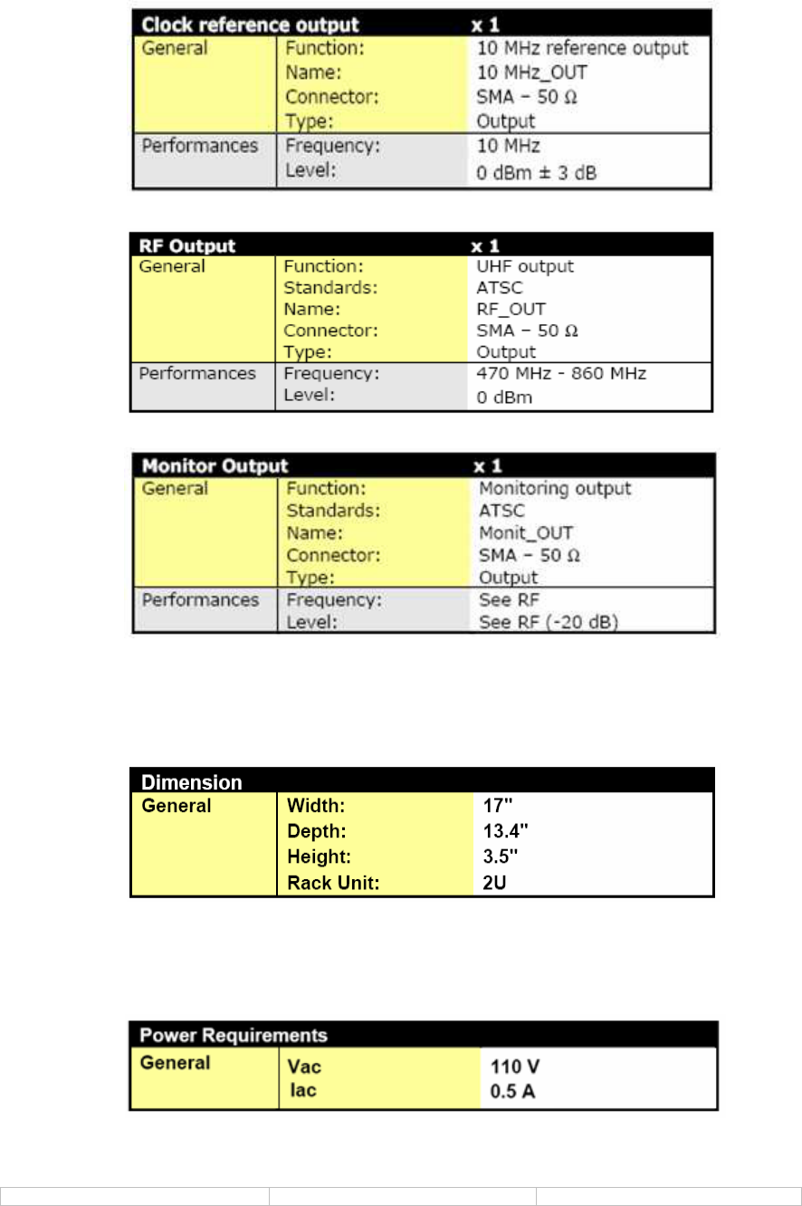
8-VSB Agile Modulator Issue 1.01 April 28, 2008 Page 13 of 1
www.technalogix.ca
Physical Characteristics
Electrical Specifications
8-VSB Agile Modulator Issue 1.01 April 28, 2008 Page 14 of 1
www.technalogix.ca
Principle of operation / Block Diagram
The input of 8-VSB modulator is a MPEG-2 Transport Stream (TS) based on MPEG-2
at a fixed bit rate of 19.39265846Mbs. The TS has 188 byte packet structure. The 8-VSB
spectrum is contained in a 6 MHz channel.
The first byte (sync byte) of the MPEG-2 data packet is stripped and the remaining 187
bytes are randomized using a polynomial generator to prevent long strings of fixed
states (1 or 0) that may occur and could increase chances of error.
The Reed Solomon encoder operates on blocks of 187 data bytes to produce blocks of
207 bytes (data plus forward error correction bytes).
The data is then interleaved in order to spread the bits to make it more immune to burst
noise.
The trellis encoder converts each byte to four 8-level channel symbols. This is important
for the modulation stage.
The Mux inserts a sync byte after each 828 symbols. This is inserted to recover
synchronization of the MPEG packets as the MPEG sync bytes are removed.
The low level pilot is added to the baseband data. The low level pilot is 11.3 dB below
the average data signal power. The pilot is inserted 310 KHz from the lower band edge.
The low level pilot aids carrier recovery and is independent of data.
The VSB modulator processes symbols to produce a very short pulse occurring at
exactly the center of the symbol times but still maintains their proper 8-levels of
amplitude. These short pulses are then applied to a raised cosine filter (Nyquist Filter).
The signal is then up-converted to 44 MHz IF and then to the desired RF channel.
The output of RF channel coming from the modulator is amplified by the power amplifier.
MUX
Pilot
Insertion
VSB
Modulator
RF
Up-Converter
Signal Processing
Encoding
MPEG-2
TS
Data
Randomizer
Reed Solomon
Encoder
Data
Interleaver
Trellis Encoder
Segment
Synch
Field
Synch
RF
Amplifier
8-VSB Agile Modulator Issue 1.01 April 28, 2008 Page 15 of 1
www.technalogix.ca
Data Input Interfaces
The module accepts a MPEG2-Transport Stream dedicated to ATSC transmission as
specified in SMPTE-310 and ATSC Standard A/53. It also supports an ASI-320 stream
format. Two data inputs are implemented to allow for an input data stream redundancy
(Primary input / Secondary input).
Data Input Management
The data input management consists of several processes:
• Bit rate adaptation and PCR (Program Clock Reference) re-stamping:
Input
Management
ATSC Framing Non Linear
Pre-correction
ASI1
ASI2
SMPTE1
SMPTE2
TS
I(nt)
Q(nt)
I(nt)
Q(nt)
IQ Digital
Modulator DAC
I(nt)
Q(nt) IF
Upconverter
RF OUT
Bandpass Filter
RF Monitor
Low Noise
Synthesizer
Power Supply Control and
Monitoring
Clock
Management
10MHz In
10MHz Out
12Vdc In
RS232

8-VSB Agile Modulator Issue 1.01 April 28, 2008 Page 16 of 1
www.technalogix.ca
The ATSC transmission scheme relies on a very stable and accurate data stream
clock. The SMPTE-310 data clock will be at the exact standardized clock
frequency. At the same time, the modulator will synchronize with this input data
stream to be able to recover the same clock. In the case of using an external
clock reference (10 MHz), the global clock synchronization might be
plesiochronous (i.e. a small clock deviance between the multiplexer clock and the
modulator reference clock). In that case, it is recommended to enable the “bit
rate adaptation” on the modulator. When this mode of operation is enabled, the
unit discards or inserts Null packets to adapt the MPEG-TS input bit rate to the
precise bit rate defined by the ATSC mode. PCR re-stamping is then executed
accordingly.
• Switching performance:
The switching is not expected to be seamless. However, in the case of feeding
the exact same data stream on both inputs (Primary & Secondary), the modulator
will perform seamless switching from one input to the other. Switching is made
on a per packet basis.
• Automatic mute:
The user can enable or disable the automatic mute for when an error on either
the SMPTE-310 or the ASI-320 input is detected. The delay for the detection of
the loss of the SMPTE-310 input is 1 second. In case the user disables the
automatic mute, null packets are inserted to reach the required bit rate.
• Test mode:
Test modes available:
- 23 bits of random data sequence
- Single tone insertion
Output Interface Management
• Channel Encoding:
The modulator performs channel encoding according to the ATSC standard:
- Randomization (energy dispersal)
- Reed Solomon coding (RS coding)
- Data field interleaving
- Trellis coding (constellation building)
• Channel modulation:
The modulator performs channel modulation according to the ATSC standard:
- Frame building
- Pilot insertion
- Constellation mapping
- Nyquist filter
• Output processes:
- Linear pre-correction.
The modulator can perform linear pre-correction adjustment. It is
possible to configure the amplitude and group delay values. The group
delay correction is from -2 to +2µs while the amplitude adjustment is +/-
3dB. A Tilt function has been implemented to correct for up-converter
distortions. It uses a set of 64 coefficients that are computed by the
control software.

8-VSB Agile Modulator Issue 1.01 April 28, 2008 Page 17 of 1
www.technalogix.ca
Using the software, the user will define their linear pre-correction
curve. Then the points will be used to compute complex coefficients to be
sent to the module. It needs 64 complex coefficients and these
coefficients are used in the module to configure the filter.
- Non Linear pre-correction.
The modulator can perform non linear pre-correction over a 20 MHz
bandwidth. The modulator can also perform amplitude and phase
correction over the full spectrum of the signal. For these purpose two
tables (AM-AM and AM-PM) of a maximum of 16 points (abscissa and
ordinate values for each point) are downloaded in the modulator (“1S
mode”). In “2S mode”, the user sets and downloads two groups of 16
points for each table. The first group corrects the “left” side of the
spectrum and the second group corrects the “right” side of the spectrum.
The “2S” mode provides more pre-correction adjustment accuracy and
allows the opportunity to perform different pre-corrections that will have a
corresponding impact on the left and right sides of the spectrum. This has
been developed particularly to correct asymmetric shoulder levels. Each
table defines the amplitude and the phase pre-correction that will be
applied on the spectrum.
The AM-AM pre-correction table defines the AM/AM curve that will be
applied across the channel spectrum. For each point, the abscissa can be
defined from -12 dB to +12 dB in 0.05 dB steps and the ordinate can be
defined from -6 dB to +6 dB in 0.05 dB steps.
The AM-PM pre-correction table defines the AM/PM curve that will be
applied to the spectrum. For each point, the abscissa can be defined from
-12 dB to +12 dB in 0.05 dB steps and the ordinate can be defined from -
25° to +25° in 0.2° steps. All 16 points are equally spaced over the useful
spectrum in 1S mode and over each left/right segment of the spectrum in
2S mode. These tables can easily be defined by using the control
software.
• RF Output signal:
The main signal is available on the “RF Out”.
The centre frequency of the signal can be set from:
- 470 MHz to 860 MHz with a step of 1 Hz.
The user will be able to setup attenuation between 0 to 10 dB in 0.1 dB steps. An
offset gain is also available from -2 to +2 dB in 0.1 dB increments if finer
adjustment is desired. The output can be muted either by the user or by pre-
determined conditions. The mute can be direct (abrupt muting) or progressive.
A sample of the signal is available at the test point at an attenuated level of -20
dB.

8-VSB Agile Modulator Issue 1.01 April 28, 2008 Page 18 of 1
www.technalogix.ca
4.0
I
NSTALLATION
This section contains installation recommendations, unpacking, inspection, and
installation instructions for the Technalogix TM600-8VSB Modulator. Carefully read all
material in this section prior to installation. Also, read and review the operating
procedures later in this section.
Building Recommendations
The quality of the building is of great importance if you are to expect long life and
continued performance from the modulator. The building must be clean, dry,
temperature controlled and secure. The modulator takes up a single 2-U high space on a
19” rack. Do not forget to allow space in the building for any additional racks to house
test equipment, a workbench area, line regulating transformers, ladders, equipment and
parts storage, first aid kit, emergency generator if used, as well as heating and cooling
devices that may be unique to your installation. A sloping roof will tend to develop leaks
less rapidly. The building should be well roofed with good material. The cooling load will
be lowered with reflective or light colored roofing material.

8-VSB Agile Modulator Issue 1.01 April 28, 2008 Page 19 of 1
www.technalogix.ca
Heating and Cooling Requirements
The environment’s temperature will contribute greatly to the length of the modulator’s
life. Technalogix recommends that the building’s filtered air intake must have capacity for
all air-flow in the building plus an additional 20%. Keep the intake below the roofline to
avoid intake of solar heated air. Please ensure that the intake and exhaust areas are on
the same side of the building to avoid pressure differentials during windy conditions.
Also, do not position intake near exhaust’s preheated air. If air conditioning is required to
cool the shelter, discuss the situation with a qualified HVAC technician. Under average
conditions, 12,000 BTUs will cool approximately 500 square feet to a comfortable level.

8-VSB Agile Modulator Issue 1.01 April 28, 2008 Page 20 of 1
www.technalogix.ca
Electrical Service Recommendations
Technalogix recommends that a qualified, licensed local electrician be consulted for the
required electrical service. We suggest local electricians because:
• The personnel knows the local codes
• The personnel can be on site readily
• You are apt to get better overall support if you give what business you can to local
suppliers
Technalogix recommends that proper AC line conditioning and surge suppression be
provided on the primary AC input to the power amplifier. All electrical service should be
installed with your national electrical code in your area, any applicable provincial or state
codes, and good engineering practice. Special consideration should be given to lightning
protection of all systems in view of the vulnerability of most transmitter sites to lightning.
Lightning arrestors are recommended in the service entrance. Straight and short
grounds are recommended. The electrical serviced must be well grounded. Do not
connect the unit to an open delta primary power supply, as voltage fluctuations could
harm the unit. Branch your circuits. Do not allow your lights, your workbench plugs, and
your transmitting or translating equipment off of one circuit breaker. Each transmitter
should have its own circuit breaker, so a failure in one does not shut off the whole
installation.

8-VSB Agile Modulator Issue 1.01 April 28, 2008 Page 21 of 1
www.technalogix.ca
Antenna and Tower Recommendations
Your preliminary engineering workgroup should establish your antenna and tower
requirements, both for receiving and transmitting antennas. Construction of sturdy, high
quality antenna/tower systems will pay off in terms of coverage of your service area, the
overall quality and saleability of your radiated signal, and reduced maintenance
expenses. Technalogix provides complete turnkey antenna systems if needed.
Transmitting antennas can enhance or seriously impair the transmitter output. It is
assumed that one has been selected prior to system installation, but the best-designed
antenna system will function poorly if shortcuts and compromises are used during
installation. Follow the manufacturer’s instructions exactly, along with any engineering
data prepared for the site.
The selection, routing, and length of coaxial cable are extremely important in the
installation. If there is a 3 dB line loss in the cable between your unit’s output and the
transmitting antenna, a 500 watt unit will only deliver 250 watts to the antenna. Buy the
best cable you can obtain, route it via the shortest way to the antenna, and keep it
straight. Do not form it into sharp bends on its way. Do not use any more cable fittings
for the installation than absolutely necessary. All cautions here apply equally to all
coaxial cables in the system - input and output. The better known tower manufacturers
offer complete technical and safety documentation with their towers. Be sure that you
have this information as it regards wind loading, guying, etc. Be absolutely safe and
certain about this aspect as human lives may be at stake.

8-VSB Agile Modulator Issue 1.01 April 28, 2008 Page 22 of 1
www.technalogix.ca
Shelter Security
The FCC requires that the transmitter be secure from entry or control by unauthorized
persons, and that any hazardous voltages or other dangers (including most tower bases)
be protected by locks or fences as necessary to protect personnel and prevent
unauthorized tampering or operation. Security of the building further implies that it be
secure from wildlife. Use sturdy construction materials, including sheet metal if
necessary. Holes around conduit, cable, and other similar entry points should be stuffed
with steel wool and caulked to prevent entry of wildlife. Other features of security for your
shelter may include its location with respect to the prevailing wind conditions. Location
leeward of some natural topographical feature will prevent wind damage and snowdrifts.
Check the soil runoff conditions that may slow or hasten wind or water erosion and other
concerns that may be unique to your location.

8-VSB Agile Modulator Issue 1.01 April 28, 2008 Page 23 of 1
www.technalogix.ca
Unpacking and Inspection
Check the outside of the container. Carefully open the container and remove the
modulator. Retain all packing material that can be reassembled in the event that the
equipment must be returned to the factory.
EXERCISE CARE IN HANDLING EQUIPMENT DURING INSPECTION
TO PREVENT DAMAGE DUE TO ROUGH OR CARELESS HANDLING.
Visually inspect the enclosure of the modulator for damage that may have occurred
during shipment. Check for evidence of water damage, bent or warped chassis, loose
screws or nuts, or extraneous packing material in connectors. Inspect all connectors for
bent connector pins. If the equipment is damaged, a claim should be filed with the carrier
once the extent of the damage is assessed. Technalogix cannot stress too strongly the
importance of immediate careful inspection of the equipment and subsequent immediate
filing of the necessary claims against the carrier if necessary. If possible, inspect the
equipment in the presence of the delivery person. If the equipment is damaged, the
carrier is your first area of recourse. If the equipment is damaged and must be returned
to the factory, phone for a return authorization. Claims for loss or damage may not be
withheld from any payment to Technalogix, nor may any payment due be withheld
pending the outcome thereof. Technalogix cannot guarantee the carrier’s performance.
8-VSB Agile Modulator Issue 1.01 April 28, 2008 Page 24 of 1
www.technalogix.ca
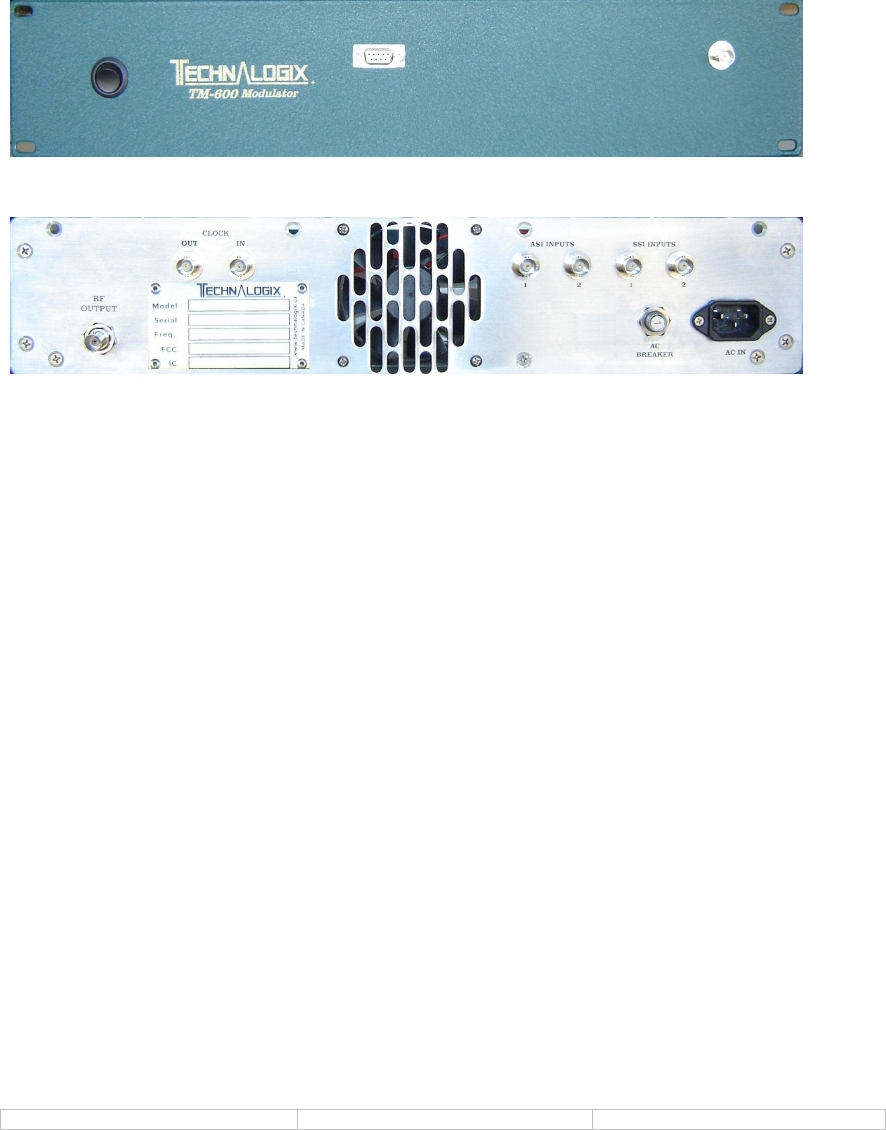
Location and Function of Controls and Connectors
The following illustrations depict the location of the installation connectors when
installing the modulator portion of the system.
FRONT
BACK
Front Panel:
Test Point- Provides a sample of the RF output level. RF test point is
only a relative indicator of the actual RF output level and
may vary. All RF operating measurements should be
made at the RF output of the unit.
RS232 - Textual low level command interface.
User supplies DB9 male to mate to DB9 female on front
panel.
Rear Panel:
ASI In - ASI-320 MPEG-2 encoded transport stream inputs (BNC).
SMPTE In - SMPTE-310 MPEG-2 encoded transport stream inputs
(BNC).
10 MHz In - Accepts external 10 MHz clock reference (BNC).
10 MHz Out – Provides a 10 MHz clock reference (BNC).
RF Output - Modulated transport stream, ATSC compliant signal
(BNC).

8-VSB Agile Modulator Issue 1.01 April 28, 2008 Page 25 of 1
www.technalogix.ca
Modulator Operation
1. Terminate modulator into a 50 ohm load before applying power.
2. Connect the power cord of the Technalogix modulator to a proper electrical
source as indicated on the back of the unit.
3. Connect the MPEG-2 encoded input to the jack on the rear panel (either ASI-320
or SMPTE-310).
4. Connect the RS232 on the front panel to a computer and run the control
software. If the power is applied and the signal is present, the power and status
LED will illuminate on the software interface.
5. Select the desired output channel by entering the center frequency on the
“Frequency” space.
6. On the front panel, connect the test point to a spectrum analyzer. Make sure that
the signal is present, at the correct frequency, and at the proper level.
• Allow for 30 seconds delay for the signal to be present after turn on.
7. Connect the RF output to a spectrum analyzer and verify the signal, the
frequency, and the level.
TECHNALOGIX POWER SUPPLIES IN THE MODULATORS ARE
DESIGNED SO THAT UNDER CERTAIN POWER LINE OR HEAT
BUILDUP CONDITIONS, THE UNIT SHUTS OFF. AN INDICATOR
WOULD BE NO RF OUTPUT. IF THIS OCCURS, UNPLUG THE
POWER CORD AND WAIT TWO MINUTES BEFORE RE-POWERING.
UPON APPLYING POWER, YOU SHOULD AGAIN HAVE RF OUTPUT.
IF NOT, OR SHOULD THE UNIT RETURN TO SHUTDOWN MODE,
PLEASE CONTACT TECHNALOGIX FOR ASSISTANCE.
TECHNALOGIX HIGHLY RECOMMENDS A 1.75 INCH AIR
CIRCULATION SPACE BETWEEN ANY PIECES OF RACK MOUNTED
EQUIPMENT.
THE MODULATOR WILL TAKE APPROXIMATELY ONE HOUR TO
REACH A STABLE OUTPUT LEVEL DUE TO TEMPERATURE WARM-
UP.
Look at the transmitted output using a suitable monitor. The picture and sound quality
should be clean and sharp. If the output picture and sound quality is unsatisfactory,
check the input signal, the input and output connections, and make sure that the
attenuation to the monitor is within the range specified by the manufacturer.

8-VSB Agile Modulator Issue 1.01 April 28, 2008 Page 26 of 1
www.technalogix.ca
THANK YOU
FOR CHOOSING
TECHNALOGIX Ltd.