Technicolor Delivery Technologies Belgium TD5130 ADSL MODEM User Manual
Technicolor Delivery Technologies Belgium ADSL MODEM
UserManual.wiki
>
Technicolor Delivery Technologies Belgium
>
TD5130 User Manual
User Manual
Navigation menu
Upload a User Manual
Namespaces
Wiki Guide
HTML
PDF
Info
Views
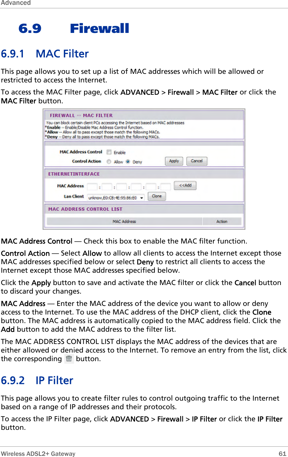
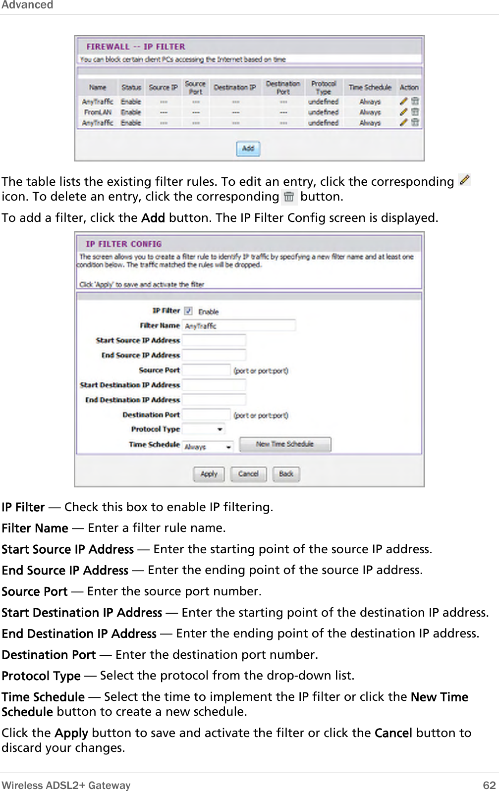
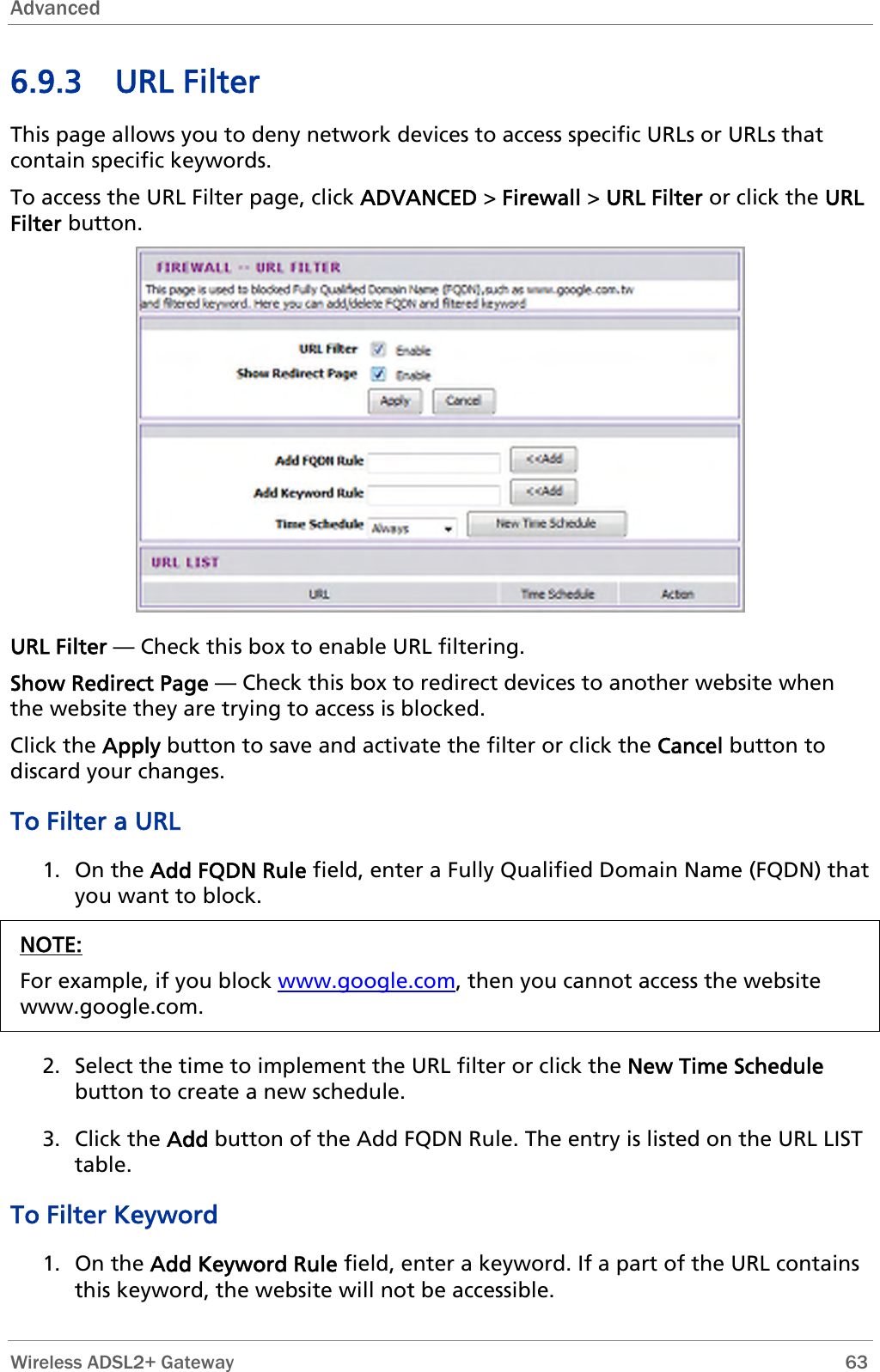
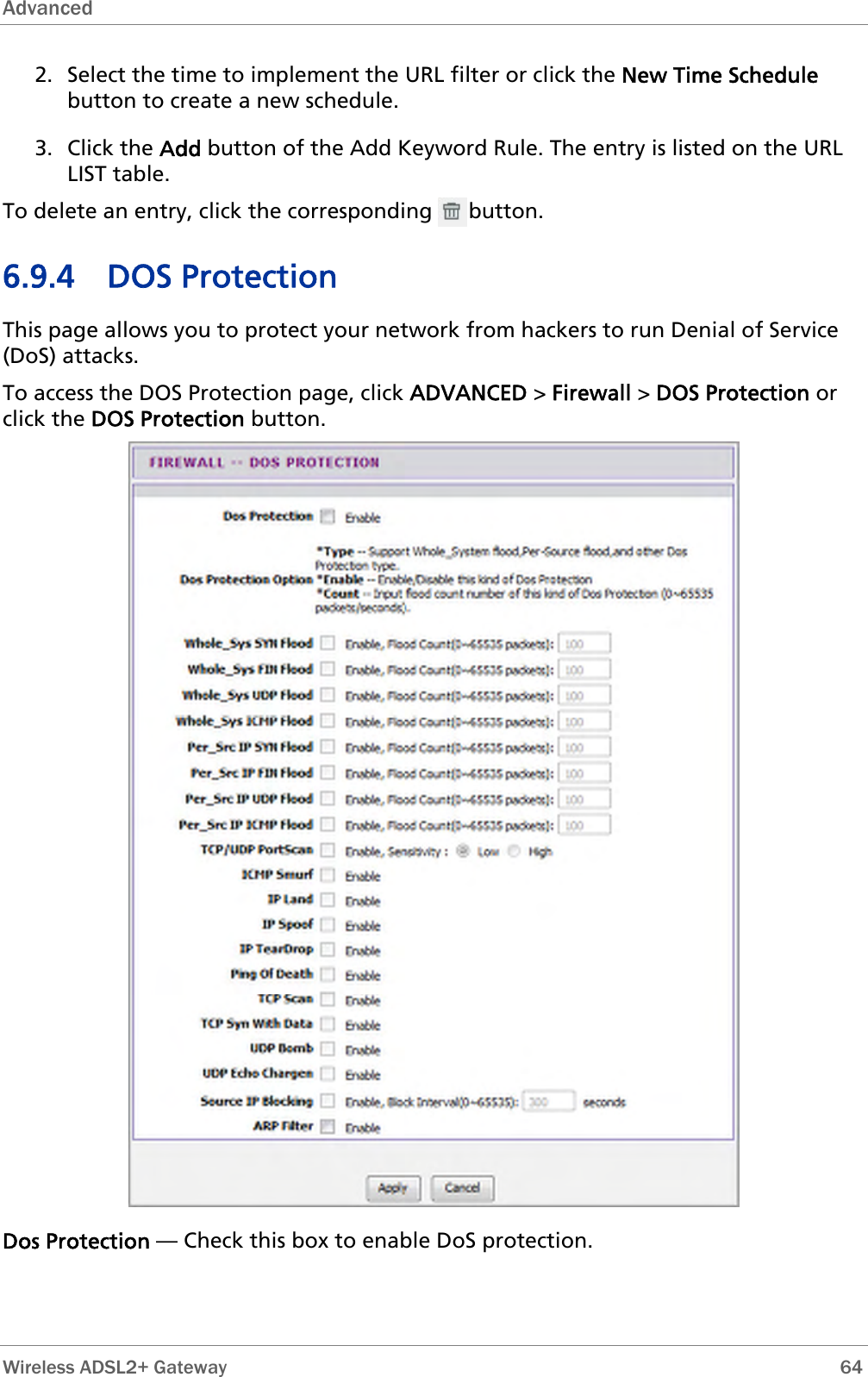
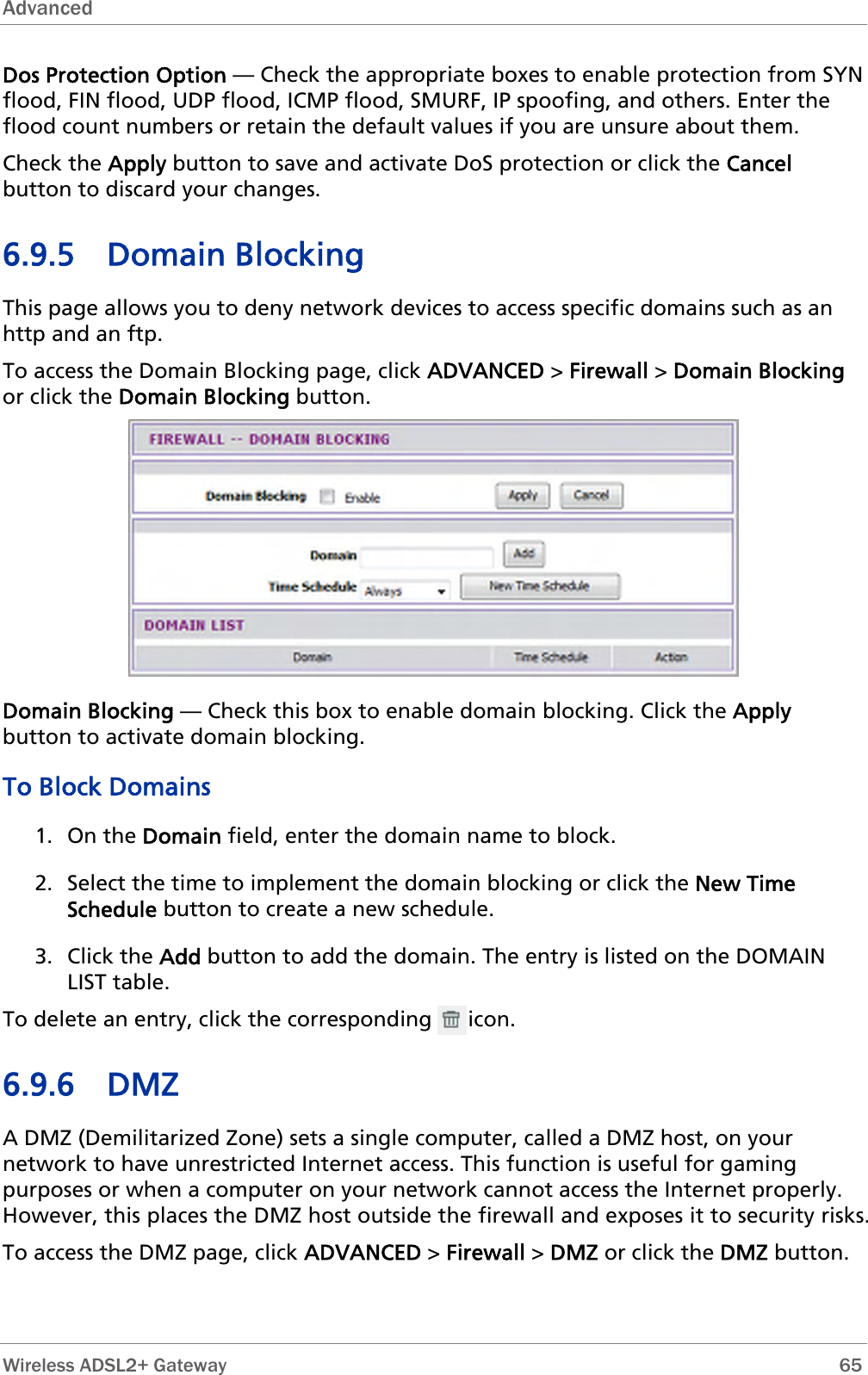
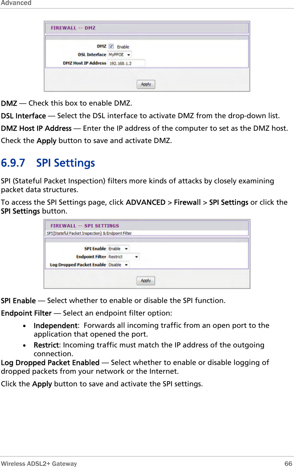
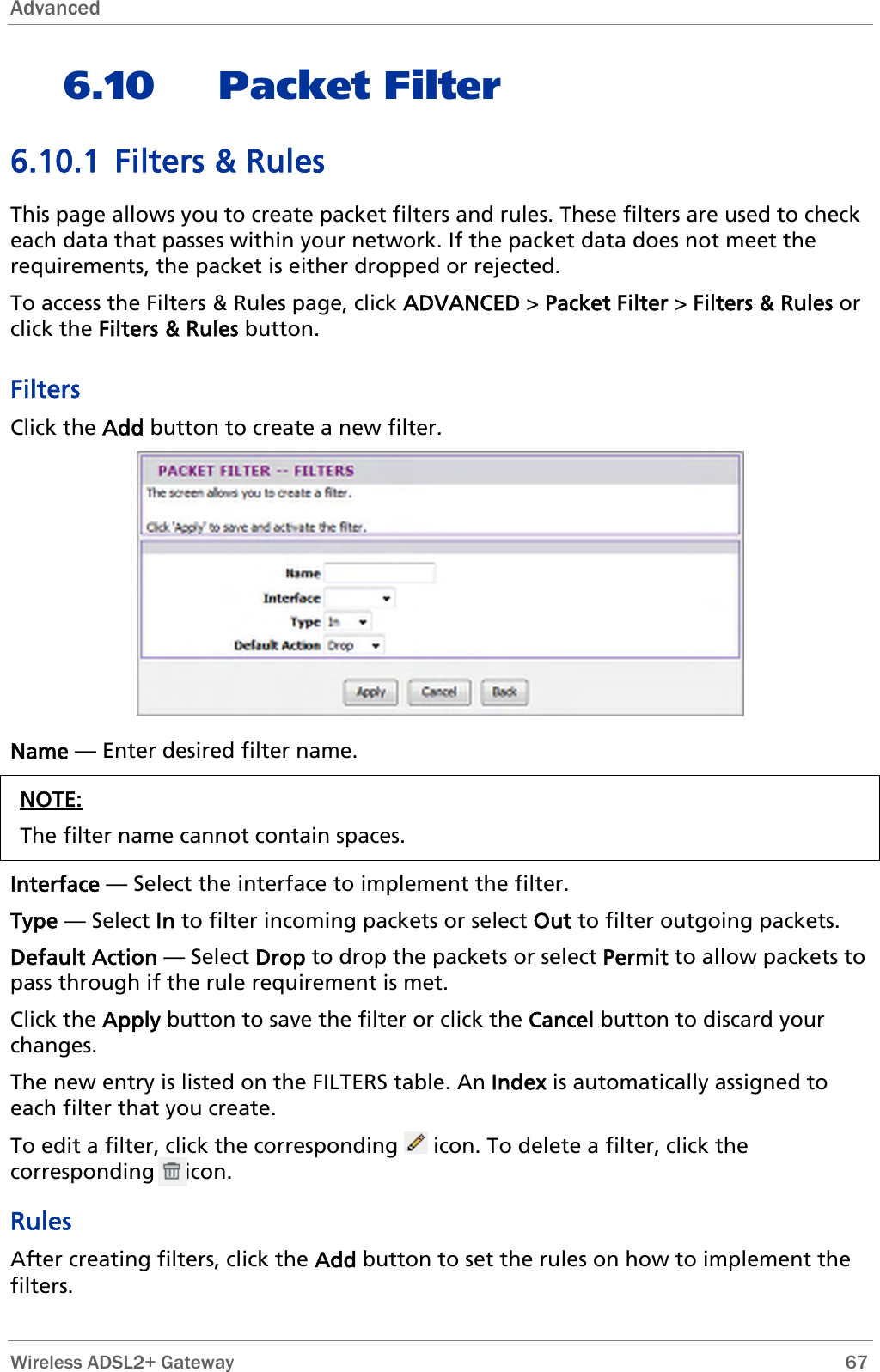
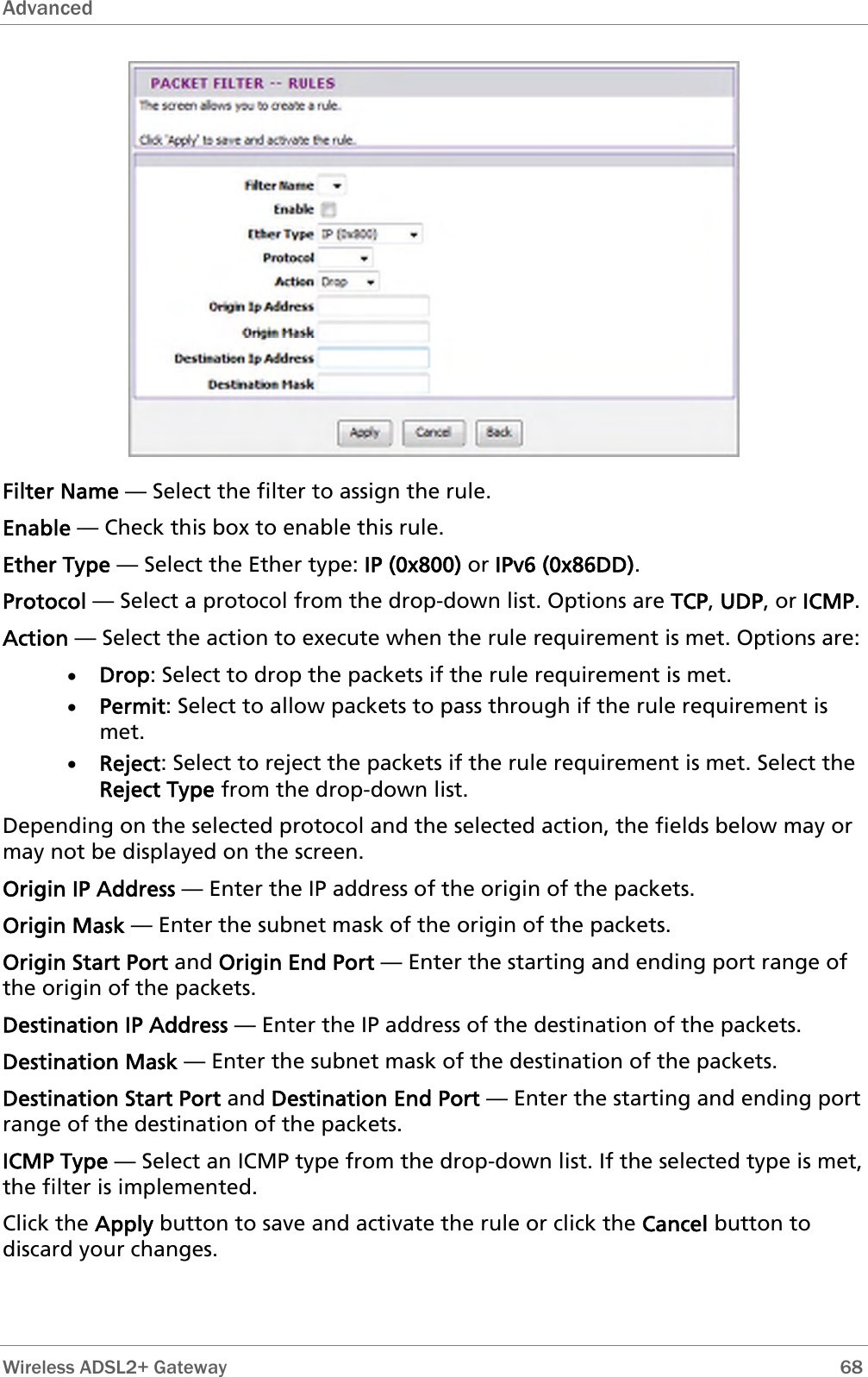
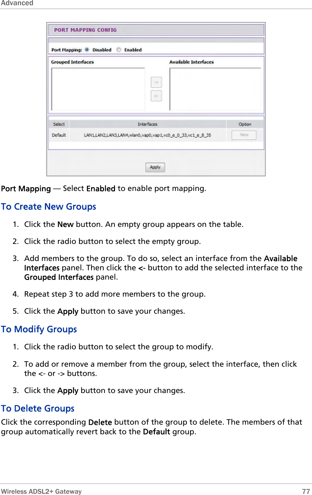
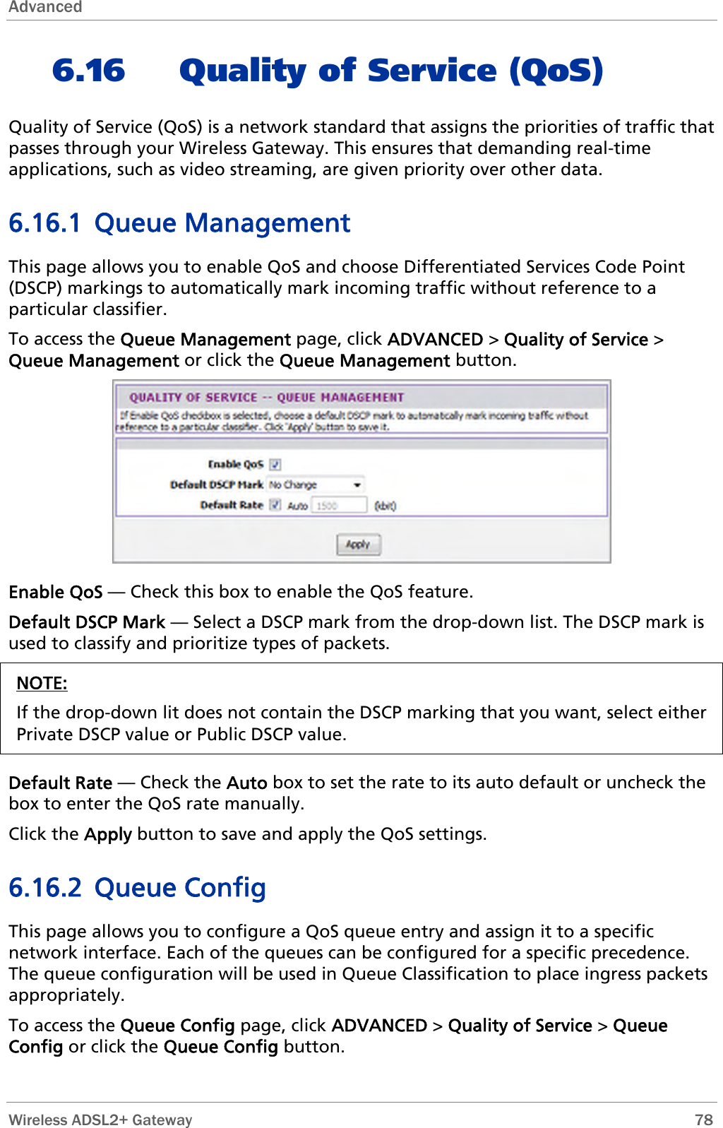
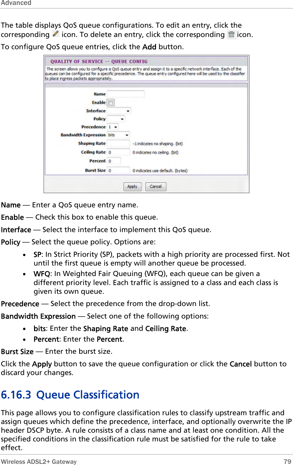
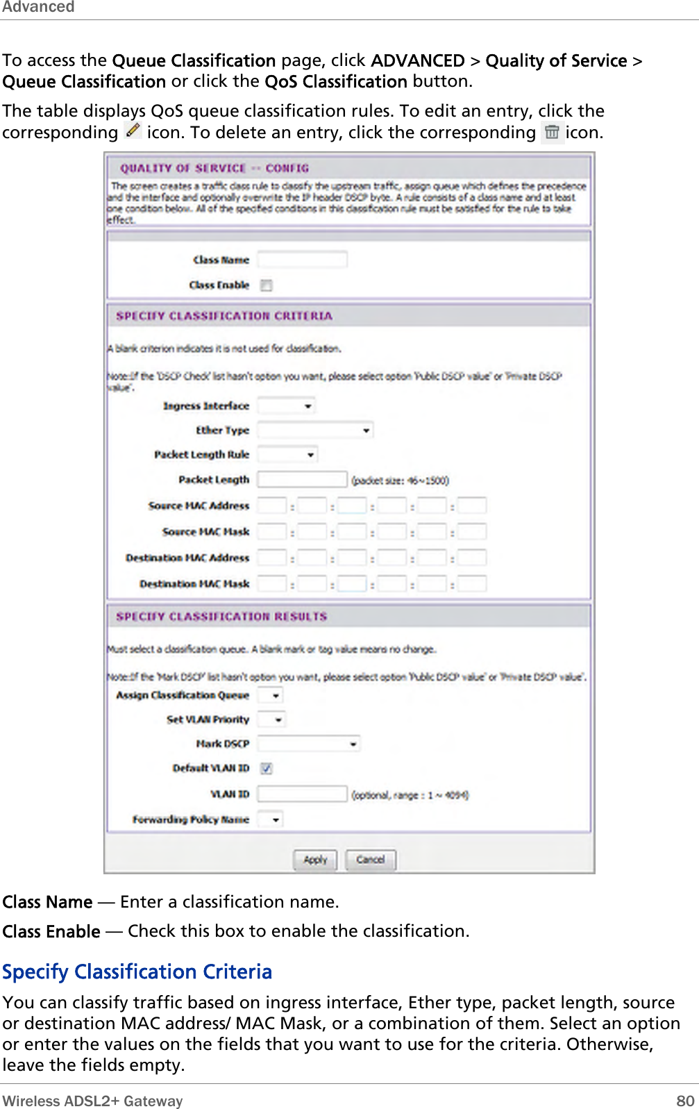
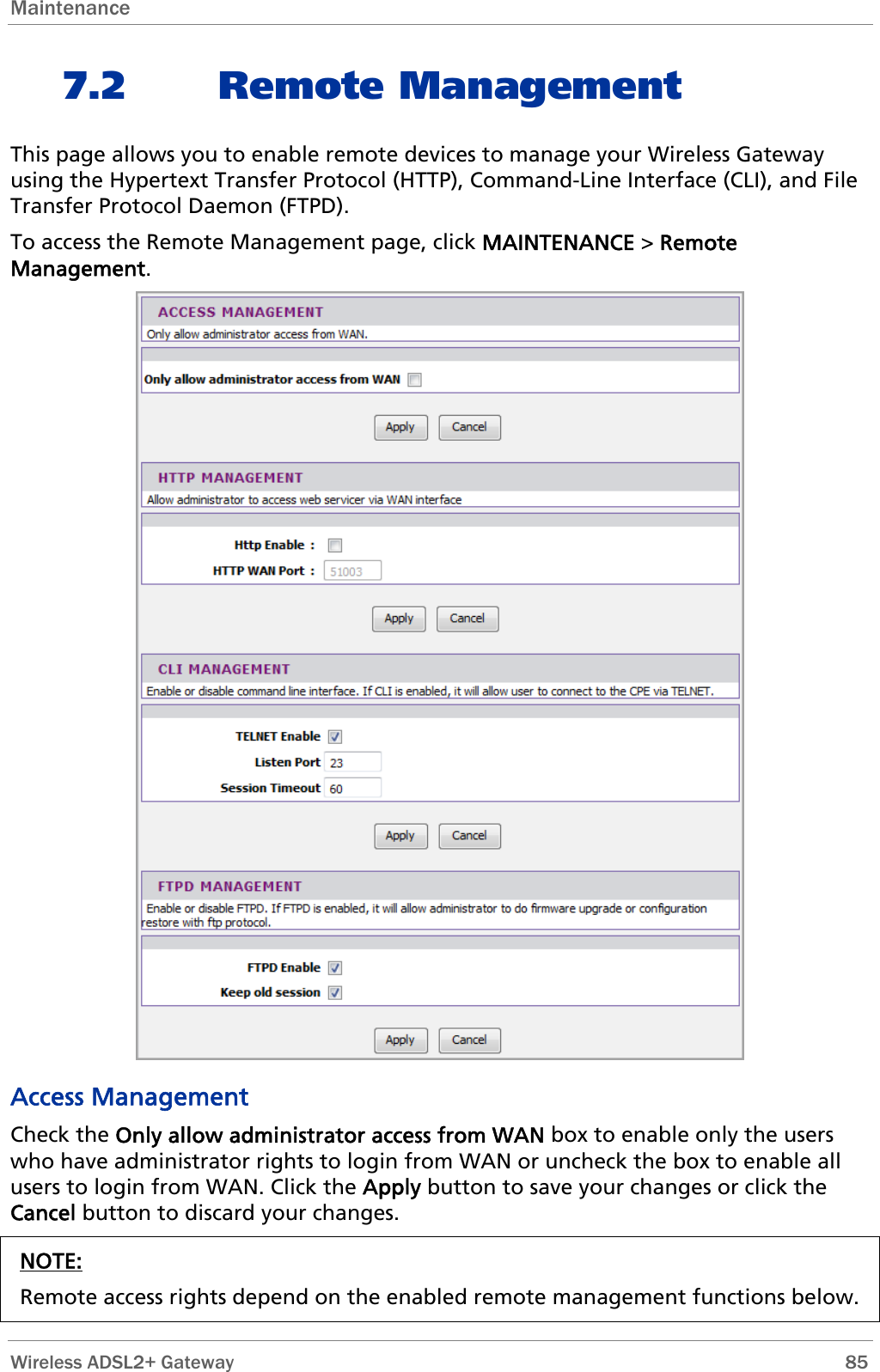
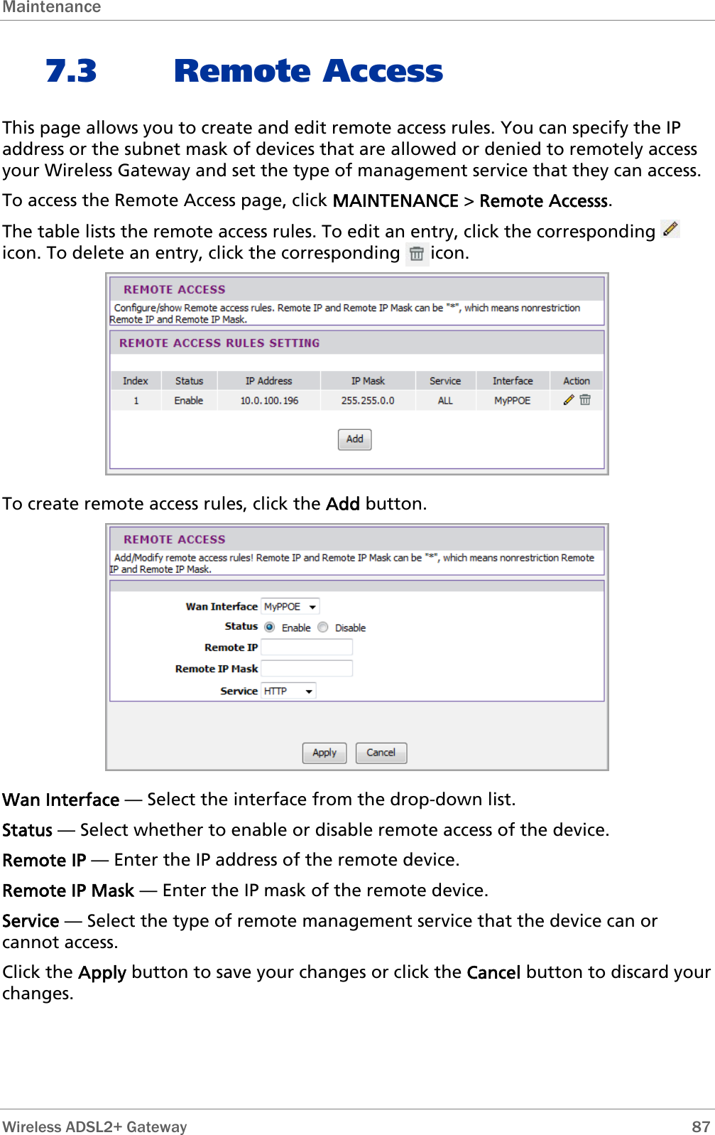
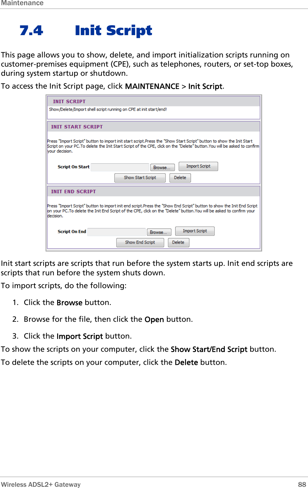
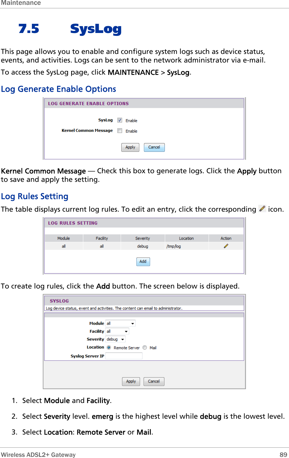
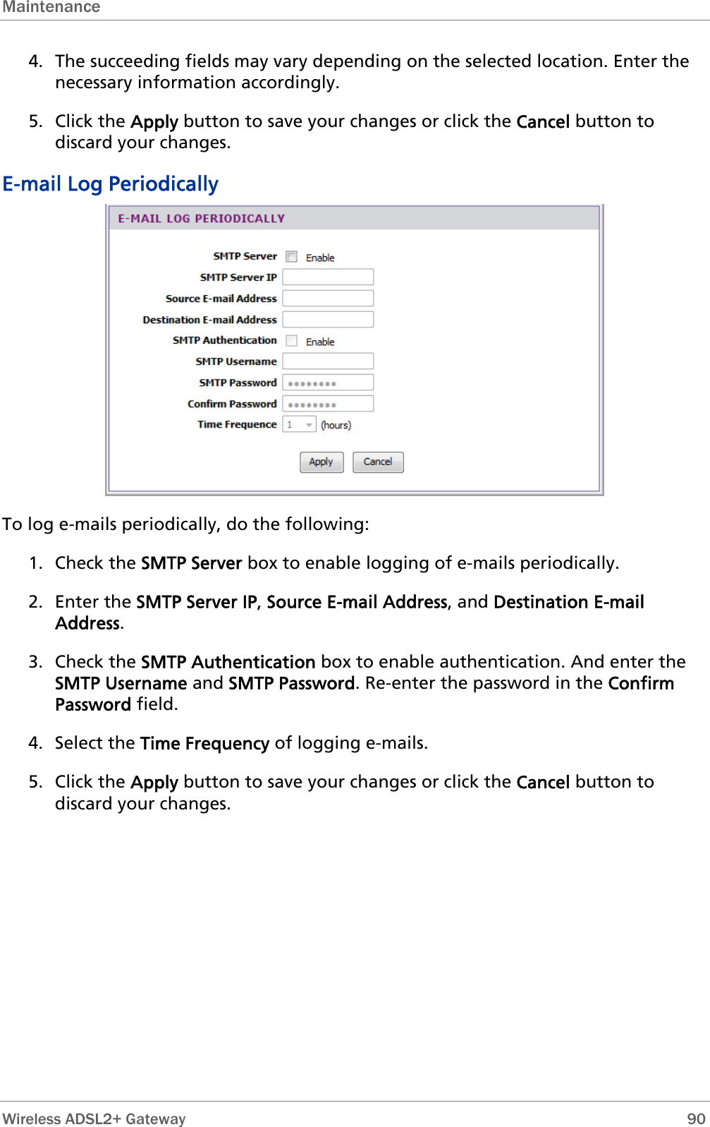
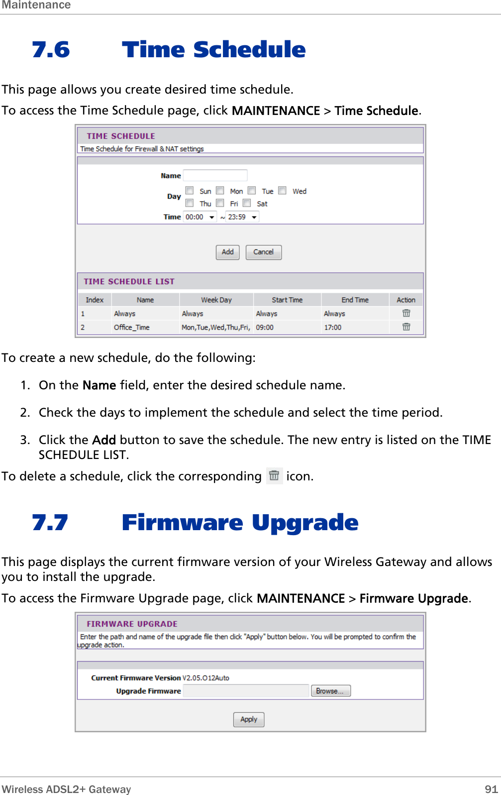
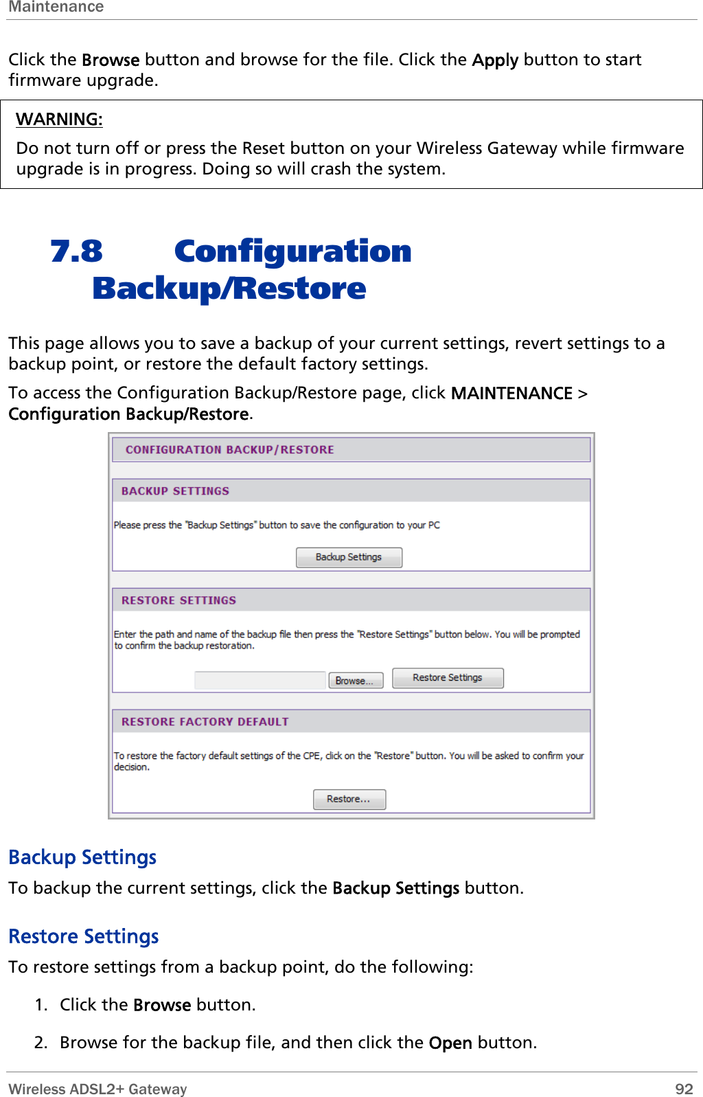
User Manual
Discussion / Help
Navigation