Technics Mt5634Smi 34 Users Manual
MT5634SMI-34 to the manual 838ccc33-5a8d-4127-b704-36f7785ed5f9
2015-02-05
: Technics Technics-Mt5634Smi-34-Users-Manual-359467 technics-mt5634smi-34-users-manual-359467 technics pdf
Open the PDF directly: View PDF ![]() .
.
Page Count: 98
- Chapter 1 – Product Description and Specification
- Chapter 2 – Mechanical Specifications
- Chapter 3 – Electrical Characteristics
- Chapter 4 – SocketModem Parallel Interface – A Pr
- Chapter 5 – AT Commands, S-Registers, and Result
- Chapter 6 - Voice Commands
- Introduction
- Voice S-Register Summary
- Voice Commands
- Commands That Change for Voice Mode Support
- Voice +V Commands Summary
- Voice +V Commands Detail
- Interface Configuration Commands
- Flow Control
- Voice Mode Result Codes
- Unsolicited Voice Mode Result Codes
- Voice Mode Shielded Codes
- Sample Sessions
- DTE/DCE Interface Rates
- Related Manuals
- Additional Information
- Chapter 7 – Fax Commands
- Chapter 8 - Remote Configuration and Country Code Configuration
- Chapter 9 – Firmware Upgrade Procedure
- Introduction
- Upgrade Overview
- Upgrade Steps
- Step 1: Identify the Modem Firmware
- Step 2: Identify the Current Version of the Firmware
- Step 3: Download the Upgrade File
- Step 4: Install the Flash Wizard
- Step 5: Extract the Firmware Upgrade (.Hex) Files
- Step 6: Document Your Stored Parameters
- Step 7: Upgrade the Modem’s Firmware
- Using the Flash Wizard
- Step 8: Restore Your Parameters
- Multi-Tech Systems, Inc. Flash Programming Protocol
- Appendix A – Mechanical Details
- Appendix B - Product Approvals, Design Considerations, and Regulatory Information
- Safety and EMC Approvals
- Telecom Approvals
- Regulatory Design Considerations
- Hardware Considerations
- Safety
- 5V Tolerant Inputs for 3.3V Modules
- FCC Part 15 Regulation
- FCC Part 68 Telecom
- Telecom Labeling Requirements
- From FCC PART 68 Subpart D – Conditions for Regis
- Fax Branding Statement
- Canadian Limitations Notice
- Industry Canada CS-03
- International Modem Restrictions
- EMC, Safety, and R&TTE Directive Compliance
- New Zealand Telecom Warning Notice
- South African Notice
- Appendix C – Country Configuration and Result Cod
- Index

Embedded Data/Fax Global Modem
MT5634SMI-34
MT5634SMI-92
Serial Build
Parallel Build
Medical Device Build
Industrial Temperature Build
Developer’s Guide

SocketModem Developer’s Guide
Serial: MT5634SMI-34, MT5634SMI-92
Parallel: MT5634SMI-P-92
Medical Device: MT5634SMI-HV-92, MT5634SMI-P-HV-92
Industrial Temperature: MT5634SMI-ITP-92, MT5634SMI-P-ITP-92
PN S000263B, Version B
Copyright
This publication may not be reproduced, in whole or in part, without prior expressed written permission from
Multi-Tech Systems, Inc. All rights reserved.
Copyright © 2003, by Multi-Tech Systems, Inc.
Multi-Tech Systems, Inc. makes no representations or warranties with respect to the contents hereof and
specifically disclaims any implied warranties of merchantability or fitness for any particular purpose. Furthermore,
Multi-Tech Systems, Inc. reserves the right to revise this publication and to make changes from time to time in
the content hereof without obligation of Multi-Tech Systems, Inc. to notify any person or organization of such
revisions or changes.
Revisions
Revision Level Date Description
A08/09/02 First release. Includes global configuration and V.92 protocol.
B06/19/03 Add V.34 documentation.
Trademarks
Trademarks of Multi-Tech Systems, Inc. are SocketModem and the Multi-Tech logo.
Microsoft and Microsoft Windows are either registered trademarks or trademarks of Microsoft Corporation in the
United States and/or other countries.
World Headquarters
Multi-Tech Systems, Inc.
2205 Woodale Drive
Mounds View, Minnesota 55112
Phone: 763-785-3500 or 800-328-9717
Fax: 763-785-9874
Technical Support
Country By Email By Phone
France: support@multitech.fr (33) 1-64 61 09 81
India: support@multitechindia.com 91 (124) 6340778
U.K.: support@multitech.co.uk (44) 118 959 7774
U.S. and Canada: oemsales@multitech.com (800) 972-2439
Rest of the World: oemsales@multitech.com (763) 717-5863
Internet Address: http://www.multitech.com

SocketModem Global MT5634SMI Developer’s Guide 3
Table of Contents
Chapter 1 – Product Description and Specifications ..............................................................................6
Introduction ................................................................................................................................................6
Product Description.................................................................................................................................... 6
Features Matrix .......................................................................................................................................... 7
Technical Specifications and Features......................................................................................................8
Chapter 2 – Mechanical Specifications...................................................................................................10
Physical Dimensions – All Models ........................................................................................................... 10
Pin Configurations.................................................................................................................................... 11
Chapter 3 – Electrical Characteristics ....................................................................................................14
Introduction ..............................................................................................................................................14
I/O Electrical Characteristics....................................................................................................................14
5V Serial – Standard (SMI) and Medical Device (SMI-HV) Build Options ..........................................14
3.3V Serial – Industrial Temperature (SMI-ITP) Build Option .............................................................14
5V Parallel – Standard (SMI) and Medical Device (SMI-HV) Build Options .......................................14
3.3V Parallel – Standard (SMI) and Industrial Temperature (SMI-ITP) Build Options........................15
Timing Requirements...............................................................................................................................15
Timing Requirements for Parallel Write ..............................................................................................15
Timing Requirements for Parallel Read .............................................................................................. 15
Handling Precautions...............................................................................................................................15
Chapter 4 – SocketModem Parallel Interface – A Programmer’s Description ....................................16
SocketModem Parallel Interface Internal Registers ................................................................................16
SocketModem MIMIC (MMM) Operation ................................................................................................. 16
Time Out Interrupts .................................................................................................................................. 18
Register Functional Descriptions ............................................................................................................. 18
Internal Registers.....................................................................................................................................18
SCR Scratch ............................................................................................................................................22
DLL Divisor Latch (LSByte)......................................................................................................................22
DLM Divisor Latch (MSByte).................................................................................................................... 22
Chapter 5 – AT Commands, S-Registers, and Result Codes ...............................................................23
Introduction ..............................................................................................................................................23
AT Command Summary ..........................................................................................................................23
AT Commands ......................................................................................................................................... 25
Escape AT Commands............................................................................................................................34
V.92 Commands ......................................................................................................................................35
S-Registers ..............................................................................................................................................40
Result Codes ...........................................................................................................................................42
Chapter 6 - Voice Commands ..................................................................................................................44
Introduction ..............................................................................................................................................44
Voice S-Register Summary...................................................................................................................... 45
Voice Commands.....................................................................................................................................45
Commands That Change for Voice Mode Support..................................................................................45
Voice +V Commands Summary............................................................................................................... 46
Voice +V Commands Detail.....................................................................................................................46
Interface Configuration Commands ......................................................................................................... 57
Flow Control............................................................................................................................................. 58
Voice Mode Result Codes .......................................................................................................................58
Unsolicited Voice Mode Result Codes..................................................................................................... 59
Valid Complex Event Report Tags ...................................................................................................... 59
Voice Mode Shielded Codes....................................................................................................................60
Sample Sessions .....................................................................................................................................62

SocketModem Global MT5634SMI Developer’s Guide 4
Sample Rate Selection and Suggested Compression Method...........................................................62
Answer Phone, Play Greeting Message, and Record Message Example.......................................... 63
DTE/DCE Interface Rates........................................................................................................................65
Related Manuals...................................................................................................................................... 65
Additional Information .............................................................................................................................. 65
Chapter 7 – Fax Commands....................................................................................................................66
Chapter 8 - Remote Configuration and Country Code Configuration .................................................67
Remote Configuration..............................................................................................................................67
Basic Procedure .................................................................................................................................. 67
Setup ...................................................................................................................................................67
Country Code Configuration ....................................................................................................................68
Using the Global Wizard Utility............................................................................................................68
Using AT Commands ..........................................................................................................................68
Chapter 9 – Firmware Upgrade Procedure ............................................................................................. 69
Introduction ..............................................................................................................................................69
Flash Upgrade Firmware.....................................................................................................................69
Multi-Tech’s Flash Programming Protocol ..........................................................................................69
Upgrade Overview ...................................................................................................................................69
Upgrade Steps ......................................................................................................................................... 69
Step 1: Identify the Modem Firmware .................................................................................................69
Step 2: Identify the Current Version of the Firmware..........................................................................70
Step 3: Download the Upgrade File ....................................................................................................70
Step 4: Install the Flash Wizard...........................................................................................................70
Step 5: Extract the Firmware Upgrade (.Hex) Files ............................................................................70
Step 6: Document Your Stored Parameters........................................................................................70
Step 7: Upgrade the Modem’s Firmware ............................................................................................71
Using the Flash Wizard .......................................................................................................................71
Step 8: Restore Your Parameters .......................................................................................................71
Multi-Tech Systems, Inc. Flash Programming Protocol........................................................................... 72
1. Programming the Modem................................................................................................................72
2. Other Supported Boot Code Commands ........................................................................................ 73
3. Other Programming Concerns.................................................................................................... 73
Intel Hex Format..................................................................................................................................74
Appendix A – Mechanical Details............................................................................................................76
Serial Test/Demo Board Components ..................................................................................................... 76
5V / 3.3V Jumper – JP1...........................................................................................................................77
Serial Test/Demo Board Block Diagram..................................................................................................77
Parallel Test/Demo Board Components ................................................................................................. 78
Parallel Test/Demo Board Block Diagram ...............................................................................................79
Appendix B - Product Approvals, Design Considerations, and Regulatory Information..................80
Safety and EMC Approvals......................................................................................................................80
Telecom Approvals ..................................................................................................................................80
Regulatory Design Considerations ..........................................................................................................81
Hardware Considerations ........................................................................................................................ 81
Safety.......................................................................................................................................................82
5V Tolerant Inputs for 3.3V Modules .......................................................................................................83
FCC Part 15 Regulation...........................................................................................................................84
FCC Part 68 Telecom ..............................................................................................................................85
Telecom Labeling Requirements ............................................................................................................. 85
From FCC PART 68 Subpart D – Conditions for Registration.................................................................86
Fax Branding Statement .......................................................................................................................... 87
Canadian Limitations Notice .................................................................................................................... 87
Industry Canada CS-03 ...........................................................................................................................88
International Modem Restrictions ............................................................................................................88

SocketModem Global MT5634SMI Developer’s Guide 5
EMC, Safety, and R&TTE Directive Compliance.....................................................................................88
New Zealand Telecom Warning Notice ................................................................................................... 89
South African Notice ................................................................................................................................89
Appendix C – Country Configuration and Result Codes ......................................................................90
Index...........................................................................................................................................................95

Chapter 1 – Product Description and Specifications
SocketModem Global MT5634SMI Developer’s Guide 6
Chapter 1 – Product Description and
Specifications
Introduction
Multi-Tech’s SocketModem creates communication-ready devices by integrating data/fax/voice functionality into
a single product design. The SocketModem is a space-efficient (1" × 2.5"), embedded modem that provides
V.92/56K communication. The complete, ready-to-integrate modem dramatically reduces development time and
costs for system designers. The SocketModem complies with global Telecom requirements, can be shipped
worldwide, and is globally configurable.
This guide provides the hardware, software, testing and troubleshooting information needed to effectively
integrate the SocketModem into your equipment. It also provides:
· commands a developer can use to configure and control a data/fax/voice modem and
· result codes the modem issues in response to the commands.
Fax Commands Documents
Two separate fax command documents along with an informational fax document are available on CD and from
Multi-Tech. They are also available on the Multi-Tech Web site, or you can contact OEM Sales at:
oemsales@multitech.com
(800) 972-2439.
Product Description
The MT5634SMI SocketModem is used for integrating data and fax communications:
· It is a single-port modem, which integrates the controller, DSP, and DAA in a 1" x 2.5" form factor and
communicates to a host controller via an asynchronous serial interface
· It is available with an 8-bit parallel interface.
· It supports the ITU-T V.92 protocol.
Two SocketModem kits are available, one for serial and the other for parallel. The serial kit allows you to plug in
the SocketModem and use it as a serial modem for testing, programming, and evaluation. The parallel kit turns
the parallel module into an ISA modem. Each kit includes one development board with an RS-232 DB-25
connector, wall power adapter, RJ-11 jack, and RS-232 cable.

Chapter 1 – Product Description and Specifications
SocketModem Global MT5634SMI Developer’s Guide 7
Features Matrix
Model Build Option
Serial Interface
Parallel Interface (16C550)
v.92/56K Max. Data Speed
V.34/33.6K Max. Data Speed
V.17 Fax Class 1, 1.0, and
Class 2
Fax Class 2.0 and 2.1
V.42 Error Correction
V.42bis Data Compression
DTMF Detection
Distinctive Ring
Voice Record and Playback
MT5634SMI MT5634SMI-92 X X X X X X X X X
MT5634SMI-P-92 X X X X X X X X X
MT5634SMI-HV-92 X X X X X X X X
MT5634SMI-P-HV-92 X X X X X X X X
MT5634SMI-IT-92 X X X X X X X X X
MT5634SMI-P-IT-92 X X X X X X X X X
MT5634SMI-34 X X X
Note: SMI-92 indicates a serial build.
SMI-P-92 indicates a parallel V.92 build.
SMI-HV-92 indicates a serial V.92 high voltage medical device build.
SMI-P-HV-92 indicates a parallel V.92 high voltage medical build.
SMI-IT-92 indicates a serial V.92 industrial temperature build.
SMI-P-IT-92 indicates a parallel V.92 industrial temperature build.
SMI-34 indicates a serial V.34 build.

Chapter 1 – Product Description and Specifications
SocketModem Global MT5634SMI Developer’s Guide 8
Technical Specifications and Features
The SocketModem meets the following specifications:
Client-to-Server Data Rates Supports V.92 and V.90 data rates
Client-to-Client Data Rates 33,600; 31,200; 28,800; 26,400; 24,000; 21,600; 19,200; 16,800;
14,400; 12,000; 9600; 7200; 4800; 2400; 1200; 0-300 bps
Fax Data Rates 33,600; 31,200; 28,800; 26,400; 24,000; 21,600; 19,200; 16,800;
14,400; 12,000; 9600; 7200; 4800; 2400; 1200; 0-300 bps
Data Format Serial, binary, asynchronous (available with parallel interface)
Data Compatibility V.92, V.34 enhanced, V.34, V.32bis, V.32, V.22bis, V.22; Bell 212A and
103/113, V.21 & V.23
Fax Compatibility ITU-T “Super” Group 3; Class 1.0, 2.0, 2.1;
Group 3, Class 1 and 2, T.4, T.30, V.21, V.27ter, V.29, V.34, V.17, and
TIA/EIA TR29.2
Voice Compatibility IS-101 AT+V commands (no CODEC for speakers/microphone
interface)
Error Correction V.42 (LAP-M or MNP 3–4)
Data Compression ITU-T V.44 (6:1 throughput); V.42bis (4:1 throughput);
MNP 5 (2:1 throughput)
Serial Speeds Serial port data rates adjustable to 300, 1200, 2400, 4800, 9600,
19,200, 38,400, 57,600, 115,200, and 230,400 bps
Modes of Operation Fax online modes; full duplex over dial-up lines; data mode, command
mode, and online command mode, V.54 test mode
Flow Control XON/XOFF (software), RTS/CTS (hardware)
Command Buffer 60 characters
Transmit Level –11 dBm (varies by country setting)
Frequency Stability ±0.01%
Receiver Sensitivity –43 dBm under worst-case conditions
AGC Dynamic Range 43 dB
Interface TTL serial or 8-bit parallel interface
Diagnostics Local analog loop, local digital loop, remote digital loop
Weight 0.02 Kg. (0.04 lb.)
Dimensions 1.045" × 2.541" × 0.680"
(2.7 x 6.5 x 1.8 cm)
DAA Isolation MT5634SMI-92
1500 Vac
MT5634SMI-HV-92 (High Voltage {5V Medical Device} Build Option)
3000 Vac

Chapter 1 – Product Description and Specifications
SocketModem Global MT5634SMI Developer’s Guide 9
Power Consumption Standard
Typical: 245 mA (1.25 W @ 5V DC)
Standby or Sleep Mode: 148mA
Maximum: 420 mA (2.1 W @ 5.25V DC)
MT5634SMI-IT-92 (Industrial Temperature {3.3V} Build Option)
Typical: 180 mA (0.59 W @ 3.3V DC)
Standby or Sleep Mode: 88mA
Maximum: 290 mA (1.04 W @ 3.6V DC)
Operating Voltage Standard
5V DC +/- 5%
Absolute Maximum Supply Voltage: 6V DC
MT5634SMI-IT-92 (Industrial Temperature {3.3V} Build Option)
3.3V DC, 180mA
Absolute Maximum Supply Voltage: 3.6V DC
Operational Temperature
Range
Standard
0–+70° C ambient under closed conditions; humidity range 20–90%
(non-condensing)
MT5634SMI-IT-92 (Industrial Temperature {3.3V} Build Option)
-40–+85° C ambient under closed conditions; humidity range 20–90%
(non-condensing)
Storage Temperature -50–+100° C
Cleaning No cleaning/washing due to the manufacturing process used to produce
this product
Intelligent Features fully AT command compatible
leased line operation
sleep mode
autodial, redial
pulse or tone dial
dial pauses
auto answer
adaptive line probing
automatic symbol and carrier frequency during start-up, retrain, and
rate renegotiations
DTMF detection
call status display, auto-parity and data rate selections
keyboard-controlled modem options
on-screen displays for modem option parameters
remote configuration
DTR dialing
phone number storage
flash memory for firmware updates
NVRAM storage for user-defined parameters
Chapter 2 – Mechanical Specifications
SocketModem Global MT5634SMI Developer’s Guide 10
Chapter 2 – Mechanical Specifications
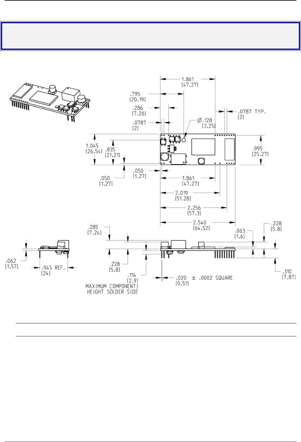
Physical Dimensions – All Models
Figure 2–1. Maximum Component Height
CAUTION: If any component(s) is placed under the SocketModem or if any component(s) should extend to the
point where part of it is under the SocketModem, the component(s) must NOT exceed .060 inches in height.
Chapter 2 – Mechanical Specifications
SocketModem Global MT5634SMI Developer’s Guide 11
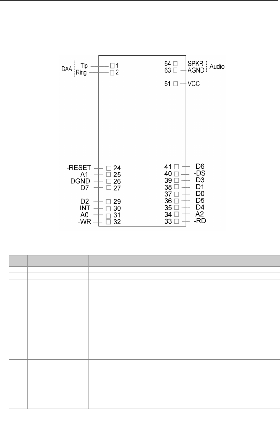
Pin Configurations
The MT5634SMI SocketModem uses a 20-pin interface to provide an on-board DAA with tip and ring
connections, audio circuit for call-progress monitoring, LED driver for call status annunciation, and serial
interface.
Figure 2–2. Serial SocketModems Pins
Pin Descriptions for Serial SocketModem Devices
Pin # Signal Name I/O Type Description
26 DGND Digital Ground
33 –RTS I Request to Send. RTS signal is used for hardware flow control.
34 –RXD O Received Data. The modem uses the RXD line to send data received from
the telephone line to the DTE and to send modem responses to the DTE.
During command mode, –RXD data presents the modem responses to the
DTE. Modem responses take priority over incoming data when the two signals
are in competition for –RXD. When no data is transmitted, the signal is held in
mark condition.
35 –TXD I Transmitted Data. The DTE uses the –TXD line to send data to the modem
for transmission over the telephone line or to transmit commands to the
modem. The DTE should hold this circuit in the mark state when no data is
being transmitted or during intervals between characters.
36 –RI O Ring Indicate. –RI output ON (low) indicates the presence of an ON segment
of a ring signal on the telephone line. The modem will no go off-hook when –RI
is active; the modem waits for –RI to go inactive before going off-hook.
37 –DSR O Data Set Ready. –DSR indicates modem status to the DTE. –DSR OFF
(high) indicates that the DTE is to disregard all signals appearing on the
interchange circuits except Ring Indicator (–RI). It reflects the status of the
local data set and does not indicate an actual link with any remote data
equipment.
38 –CTS O Clear To Send. –CTS is controlled by the modem to indicate whether or not
the modem is ready to transmit data. –CTS ON indicates to the DTE that
signals presented on TXD will be transmitted to the telephone line. –CTS OFF

Chapter 2 – Mechanical Specifications
SocketModem Global MT5634SMI Developer’s Guide 12
indicates to the DTE that it should not transfer data across the interface on
TXD.
39 –DCD O Data Carrier Detect. –DCD output is ON (low) when a carrier is detected on
the telephone line or OFF (high) when carrier is not detected.
40 –DTR I Data Terminal Ready (Active Low). The –DTR input is turned ON (low) by
the DTE when the DTE is ready to transmit or receive data. –DTR ON
prepares the modem to be connected to the telephone line, and, once
connected, maintains the connection. –DTR OFF places the modem in the
disconnect state.
41 DGND GND
61 VCC PWR +5V or 3.3V Supply (depends upon model).
63 AGND GND Analog Ground. Analog ground is tied common with DGND on the
SocketModem. To minimize potential ground noise issues, connect audio
circuit return to AGND.
64 SPKR Speaker Output. SPKR is a single ended-output. SPKR is tied directly to the
CODEC.
LED driver outputs are open-drain inverter-driven (74HCT05) lines with 1.5K ohms pull-up resistors. Max
output current 25 mA.
1 Tip I/O Tip Signal from Telco.
2 Ring I/O Ring Signal from Telco.
24 –RESET I Modem Reset (with weak pull-up). The active low –RESET input resets the
SocketModem logic and returns the AT command set to the original factory defa
u
values or to "stored values" in NVRAM. –RESET is tied to VCC through a 400m
s
time constant circuit for "Power-on-Reset" functionality. The modem is ready to
accept commands within 6.5 seconds of power-on or reset. Reset must be asse
r
for 300 ns.
29 DCDIND O Active High DCD status.
30 RXIND O Active High RDX status
31 DTRIND O Active High DTR status
32 TXDIND O Active High TXD status
Chapter 2 – Mechanical Specifications
SocketModem Global MT5634SMI Developer’s Guide 13
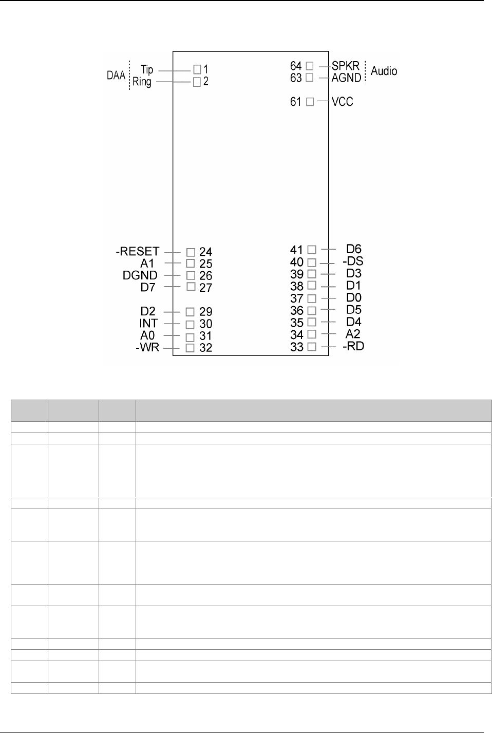
The MT5634SMI-P (Parallel) SocketModem uses a 22-pin interface to provide an on-board DAA with tip and ring
connections, audio circuit for call-progress monitoring, and parallel interface.
Figure 2–3. Parallel SocketModem Pins
Pin Descriptions for a Parallel SocketModem Device
Pin # Signal
Name I/O Description
1 Tip I/O Tip Signal from Telco
2 Ring I/O Ring Signal from Telco
24 –RESET I Modem Reset (with weak pull-up). The active low –RESET input resets the
SocketModem logic and returns the AT command set to the original factory default
values or to "stored values" in NVRAM.
The modem is ready to accept commands within 6.5 seconds of power-on or reset.
Reset must be asserted for a minimum of 300 ns.
26 DGND GND Digital Ground
25, 31,
34
A0, A1,
A2
IHost Bus Address Lines 0 and 2. During a host read or write operation, A0
through A2 select an internal 16C450 or 16C550-compatible register. The state of
the divisor latch access bit (DLAB) affects the selection of certain registers.
30 INT O Host Bus Interrupt. INT output is set high when the receiver error flag, receiver
data available, transmitter holding register empty, or modem status interrupt have
an active high condition. INT is reset low upon the appropriate interrupt service or
master reset operation.
32 –WR I Host Bus Write. –WR is an active low, write control input. When –DS is low, –WR
low allows the host to write data or control words into a selected modem register.
33 –RD I Host Bus Read. –RD is an active low, read control input. When –DS is low, –RD
low allows the host to read status information or data from a selected modem
register.
40 –DS I Host Bus Device Select. –DS input low enables the modem for read or write.
61 VCC PWR +5V or 3.3V Supply (depends upon model).
63 AGND GND Analog Ground. This is tied common with DGND on the SocketModem. To
minimize potential ground noise issues, connect audio circuit return to AGND.
64 SPKR O Speaker Output. SPKR is a single ended-output. It is tied directly to the CODEC.

Chapter 3 – Electrical Characteristics
SocketModem Global MT5634SMI Developer’s Guide 14
Chapter 3 – Electrical Characteristics
Introduction
Electrical characteristics for the 5V Serial SocketModem, 3.3V Serial SocketModem, 5V Parallel SocketModem,
and the 3.3V Parallel SocketModem are presented in this chapter.
I/O Electrical Characteristics
5V Serial – Standard (SMI) and Medical Device (SMI-HV) Build Options
5 Vdc Characteristics (TA = 0 °C to 50 °C; VDD = 5 V ± 0.25 V) VDDMAX = 5.25 V
Digital Inputs
–DTR (40), –TXD (35), –RTS (33), –RESET (24)
Input High
Min 3.675 V
Input Low
Max 1.4 V
Digital Outputs
–DCD (39), –CTS (38), –DSR (37), –RI (36), –RXD (34)
Output High
Min. 4 V
Output Low
Max 0.4 V
Current Drive
2 ma
Digital Input Capacitance 5 PF
3.3V Serial – Industrial Temperature (SMI-ITP) Build Option
3.3 Vdc Characteristics (TA = -40 °C to 85 °C; VDD = 3.3 V ± 0.3 V) VDDMAX = 3.6 V
Digital Inputs
–DTR (40), –TXD (35), –RTS (33), –RESET (24)
Input High
Min 2.52 V
Input Low
Max 0.9 V
Digital Outputs
–DCD (39), –CTS (38), –DSR (37), –RI (36), –RXD (34)
Output High
Min. 2.3 V
Output Low
Max 0.4 V
Current Drive
2 ma
Digital Input Capacitance 5 PF
5V Parallel – Standard (SMI) and Medical Device (SMI-HV) Build Options
5 Vdc Characteristics (TA = 0 °C to 50 °C; VDD = 5 V ± 0.25 V) VDDMAX = 5.25 V
Digital Inputs
–DS (40)
Input High
Min. 3.675 V
Max. 1.4 V
Digital Inputs (hysteresis input buffer)
A0 (31), A1 (25), A2 (34), –WR (32), –RD (33)
Input High
Min. 3.675 V
Input Low
Max. 1.4 V
Digital Input / Output
Output buffer can source 12 mA at 0.4 V
DO (37), D1 (38), D2 (29), D3 (39), D4 (35), D5 (36), D6
(41), D7 (27)
Input High
Min. 3.675 V
Input Low
Max. 1.4 V
Digital Output
INT (30)
Output High
Min. 4 V
Output Low
Max 0.4 V
Current Drive
2 ma
Digital Input Capacitance 5 PF

Chapter 3 – Electrical Characteristics
SocketModem Global MT5634SMI Developer’s Guide 15
3.3V Parallel – Standard (SMI) and Industrial Temperature (SMI-ITP) Build Options
Electrical characteristics for Parallel MT5634SMI SocketModem devices are presented below.
3.3 Vdc Characteristics (TA = –40 °C to 85 °C; VDD = 3.3 V ± 0.3 V) VDDMAX = 3.6 V
Digital Inputs
–DS (40)
Input High
Min 2.52 V
Input Low
Max 0.9 V
Digital Inputs (hysteresis input buffer)
A0 (31), A1 (25), A2 (34), –WR (32), –RD (33)
Input High
Min 2.52 V
Input Low
Max 0.9 V
Digital Input/Output
Output buffer can source 12 mA at 0.4 V
DO (37), D1 (38), D2 (29), D3 (39), D4 (35), D5 (36), D6
(41), D7 (27)
Input High
Min 2.52 V
Input Low
Max 0.9 V
Digital Output
INT (30)
Output High
Min 2.3 V
Output Low
Max 0.4 V
Current Drive
2 ma
Digital Input Capacitance 5 PF
Timing Requirements
Timing Requirements for Parallel Write
Parameter Min Max Unit
–DS to –WR Setup (low to low) 10 - ns
A0, A1, A2 to –WR Setup (valid to low) 15 - ns
–WR Pulse Width (low to high) 40 - ns
D0–D7 to –WR Setup (valid to high) 30 - ns
–WR to –DS hold (high to high) 0 - ns
–WR to A0–A2 Hold (high to invalid) 0 - ns
–WR to D0–D7 Hold (high to invalid) 0 - ns
–WR interaccess (high to low)
Non-MIMIC Accesses
MIMIC Accesses
10
110
-
-
ns
ns
Timing Requirements for Parallel Read
Parameter Min Max Unit
–DS to –RD Setup (low to low) 10 - ns
A0, A1, A2 to –RD Setup (valid to low) 15 - ns
–RD Pulse Width (low to high) 40 - ns
–RD to –DS hold (high to high) 0 - ns
–RD to A0–A2 Hold (high to invalid) 0 - ns
–WR interaccess (high to low)
Non-MIMIC Accesses
MIMIC Accesses
10
110
-
-
ns
ns
Handling Precautions
All MOS devices must be handled with certain precautions to avoid damage due to the accumulation of static charge.
Although input protection circuitry has been incorporated into the devices to minimize the effect of this static buildup,
proper precautions should be taken to avoid exposure to electrostatic discharge during handling and mounting.

Chapter 4 – SocketModem Parallel Interface – A Programmer’s Description
SocketModem Global MT5634SMI Developer’s Guide 16
Chapter 4 – SocketModem Parallel
Interface – A Programmer’s
Description
SocketModem Parallel Interface Internal Registers
The SocketModem parallel interface is a mimic of a 16C550A UART. It is similar to the MIMIC interface used in
the Zilog Z80189. The SocketModem mimic (MMM) takes advantage of this standard interface while replacing
the serial to parallel data transfer with a less complicated parallel to parallel data transfer.
The MMM interface controls an 8-bit parallel data transfer which is typically interrupt driven. Interrupts usually
indicate one or both of two conditions: (1) the receive (RX) FIFO has either reached a trigger level or time-out
condition and needs to be emptied and/or (2) the transmit (TX) FIFO is empty and waiting for more data from the
Host. An interrupt can also be triggered by a change in the modem status register (i.e., loss of carrier) or by the
occurrence of errors in the line status register (overrun, parity, framing, break detect).
In addition to the receive and transmit FIFOs, there are twelve other control/status registers called the MMM
register set which can be accessed through this interface.
SocketModem MIMIC (MMM) Operation
Data flow through MMM is bi-directional. Simultaneously, data can flow from the host through the transmit FIFO
to the SocketModem controller, and data can flow from SocketModem controller through the receive FIFO to the
Host. In the receive path, 8-bit data is asynchronously received (from the SocketModem controller) by the
receive FIFO where it is stored along with associated three error bits. The error bits must arrive (via a
SocketModem controller I/O write to MMM shadow line status register) prior to receiving the actual data bits. The
error bits are then temporarily stored so they may be written, with associated data bits, to the 11-bit wide RX
FIFO.
After every data write, the RX FIFO write pointer is incremented. RX FIFO trigger levels, data ready signal, and
time-out counter are checked to see if a Host interrupt needs to be sent. The data ready signal will be activated
and MMM sits poised to accept another data word.
We highly recommend the host should read the MMM IIR register to determine the type of interrupt. Then it might
check bit 7 of the LSR to see if there are any errors in the data currently residing in the receive FIFO. Finally, it
will (1) alternately read a data word through the RX FIFO read pointer and the error bits via the MMM LSR until
the FIFO is empty, or (2) read successive data words (knowing there were no errors in the FIFO) until the trigger
count is met.
A similar sequence occurs when data flows in the other direction (from host through transmit FIFO), except there
is no error bit manipulation/checking involved.

Chapter 4 – SocketModem Parallel Interface – A Programmer’s Description
SocketModem Global MT5634SMI Developer’s Guide 17
FIFO Operation
The 16-byte transmit and receive data FIFOs are enabled by the FIFO Control Register (FCR) bit-0. You can set
the receive trigger level via FCR bits 6/7. The receiver FIFO section includes a time-out function to ensure data is
delivered to the external host. An interrupt is generated whenever the Receive Holding Register (RHR) has not
been read following the loading of a character or the receive trigger level has been reached.
Receive (RX) FIFO
The RX FIFO can be configured to be 16 words deep and 11 bits wide. Each word in the RX FIFO consists of 8
data bits and 3 error bits. The RX block of the MMM contains read and write pointers and status flag circuitry
that need only to be presented with data (for input), reset, read/write control signals, and read/write clock signals.
The RX block of the MMM internally manages the FIFO register file and pointers, and it provides simultaneous
read/write capability (no contention problems).
The RX block of the MMM provides data (for output), FIFO full flag, FIFO empty flag, and an almost full flag
which uses an associated predefined trigger level (obtained from the MMM FCR control register) to signal when
the trigger level has been met. Four possible trigger levels may be selected by programming bits 6-7 of the FCR
control register.
A typical (interrupt driven) write to the RX block is a two-step process. The MMM micro-controller must first write
the 3 error bits to a shadow MMM LSR status register. Next, the micro-controller writes the data to the RX FIFO
and during this write operation, the 3 error bits are directly loaded from the LSR shadow register into the bits 8-
10 of the selected (11 bit-wide) FIFO register. These error bits represent the parity error, framing error, and break
interrupt signals associated with each data work transmission into the receive FIFO. When the receive FIFO is
read, these error bits are loaded directly into bits 2-4 of the MMM LSR register.
A2 A1 A0 Register Name Register Description Host Access
0
0
0
0
0
0
1
1
1
1
0
0
0
1
1
1
0
0
1
1
0
0
1
0
0
1
0
1
0
1
RBR
THR
IER
IIR
FCR
LCR
MCR
LSR
MSR
SCR
Receive Buffer (RX FIFO)
Transmit Holding (TX
FIFO)
Interrupt Enable
Interrupt Identification
FIFO Control
Line Control
Modem Control
Line Status
Modem Status
Scratch pad
DLAB = 0 R only
DLAB = 0 W only
DLAB = 0 R/W
DLAB = X R only
DLAB = X W only
DLAB = X R/W
DLAB = 0 R/W
DLAB = X R only
DLAB = X R only
DLAB = 0 R/W
0
0
1
1
0
0
1
0
0
1
1
0
DLL
DLM
DLX
MCX
LSB of Divisor Latch
MSB of Divisor Latch
Divisor Latch
Status/Control
DLAB = 1 R/W
DLAB = 1 R/W
DLAB = 1 R/W
DLAB = 1 R/W
Note 1* The General Register set is accessible only when DS is a logic 0.
Note 2* The Baud Rate register set is accessible only when DS is a logic 0 and LCR bit-7 is a logic 1.

Chapter 4 – SocketModem Parallel Interface – A Programmer’s Description
SocketModem Global MT5634SMI Developer’s Guide 18
Time Out Interrupts
The interrupts are enabled by IER bits 0-3. Care must be taken when handling these interrupts. Following a reset
the transmitter interrupt is enabled, the SocketModem will issue an interrupt to indicate that transmit holding
register is empty. This interrupt must be serviced prior to continuing operations.
The LSR register provides the current singular highest priority interrupt only. A condition can exist where a higher
priority interrupt may mask the lower priority interrupt(s). Only after servicing the higher pending interrupt will the
lower priority interrupt(s) be reflected in the status register. Servicing the interrupt without investigating further
interrupt conditions can result in data errors. When two interrupt conditions have the same priority, it is important
to service these interrupts correctly.
Receive Data Ready and Receive Time Out have the same interrupt priority (when enabled by IER bit-3). The
receiver issues an interrupt after the number of characters received have reached the programmed trigger level.
In this case the MMM FIFO may hold more characters than the programmed trigger level. Following the removal
of a data byte, the user should recheck LSR bit-0 for additional characters. A Receive Time Out will not occur if
the receive FIFO is empty. The time out counter is reset at the center of each stop bit received or each time the
receive holding register (RHR) is read.
Register Functional Descriptions
The following table delineates the assigned bit functions for the twelve internal registers. The assigned bit
functions are more fully defined in the following paragraphs.
Internal Registers
A2 A1 A0 Register
[Default]
Note *3
BIT-7 BIT-6 BIT-5 BIT-4 BIT-3 BIT-2 BIT-1 BIT-0
General Register Set: Note 1*
0 0 0 RBR [XX] Bit-7 Bit-6 Bit-5 Bit-4 Bit-3 Bit-2 Bit-1 Bit-0
0 0 0 THR [XX] Bit-7 Bit-6 Bit-5 Bit-4 Bit-3 Bit-2 Bit-1 Bit-0
0 0 1 IER [00] 0 0 0 0 Modem
Status
Interrupt
Receive
Line
Status
interrupt
Transmit
Holding
Register
interrupt
Receive
Holding
Register
interrupt
0 1 0 IIR [XX] FIFO
enable
FIFO
enable
0 0 Interrupt
ID
Interrupt
ID
Interrupt
ID
Interrupt
Pending
0 1 0 FCR [00] RX
Trigger
(MSB)
RX
trigger
(LSB)
Detect
change
in FCR
TX
FIFO
overrun
bit
DMA
mode
select
XMIT
FIFO
reset
RCVR
FIFO
reset
FIFO
enable
0 1 1 LCR [00] Divisor
latch
access
(DLAB)
Set
break
Stick
parity
Even
parity
Parity
enable
0 Word
length
bit-1
Word
length
bit-0
1 0 0 MCR [00] 0 0 0 Loop
back
INT
enable
OUT 1 -RTS -DTR
1 0 1 LSR [60] RX
FIFO
data
error
TX
empty
THR
empty
THR
Empty
Break
interrupt
Framing
error
Parity
error
Overrun
error
Receive
data
ready
1 1 0 MSR [X0] CD RI DSR CTS Delta
-CD
Delta
-RI
Delta
-DSR
Delta
-CTS
1 1 1 SCR [FF] Bit-7 Bit-6 Bit-5 Bit-4 Bit-3 Bit-2 Bit-1 Bit-0
Special Register Set: Note *2
0 0 0 DLL [00] Bit-7 Bit-6 Bit-5 Bit-4 Bit-3 Bit-2 Bit-1 Bit-0
0 0 1 DLM [00] Bit-7 Bit-6 Bit-5 Bit-4 Bit-3 Bit-2 Bit-1 Bit-0
Note 1* The General Register set is accessible only when DS is a logic 0.
Note 2* The Baud Rate register set is accessible only when DS is a logic 0 and LCR bit-7 is a logic 1.
Note 3* The value between the square brackets represents the register's initialized HEX value, X = N/A.

Chapter 4 – SocketModem Parallel Interface – A Programmer’s Description
SocketModem Global MT5634SMI Developer’s Guide 19
RBR Receive Buffer (RX FIFO)
All eight bits are used for receive channel data (host read/data in; host write/data out). The three error bits per
byte are copied into bits 2, 3, and 4 of the LSR during each host I/O read; therefore, they are available for
monitoring on a per-byte basis.
THR Transmit Holding Register (TX FIFO)
All eight bits are used for transmit channel data (host write/data out; host read/data in).
IER Interrupt Enable
Bits 4–7: Reserved and will always read 0.
Bits 0-3: Set by host software only and cleared by software control or host reset.
Bit 3: Enables modem status IRQ. If bits 0–3 of the MSR are set and this bit is set to 1 (enabled), a host
interrupt is generated.
Bit 2: Enables receive line status IRQ. If bits 1–4 (overrun, parity, framing, break errors) of the LSR are
set and this bit is set to a logic 1, a host interrupt is generated.
Bit 1: Enables transmit holding register IRQ. If bit 5 (transmit holding register empty) of the LSR is set
and this bit is set to a 1, a host interrupt is generated.
Bit 0: Enables received data available IRQ. If bit 0 (data ready) of the LSR is set and this bit is set to a 1,
a host interrupt is generated.
IIR Interrupt Identification (Read Only)
Bits 6–7: (FIFO enabled bits). These bits will read a 1 if FIFO mode is enabled and the 16450 enable bit is 0
(no force of 16450 mode).
Bits 4–5: Reserved and always read a 0.
Bits 1–3: Interrupt ID bits.
Bit 0: Interrupt pending. If logic 0 (in default mode), an interrupt is pending.
When the host accesses IIR, the contents of the register are frozen. Any new interrupts will be recorded, but not
acknowledged during the IIR access. This requires buffering bits (0–3, 6–7) during IIR reads.
Bit 3 Bit 2 Bit 1 Priority Interrupt Source Interrupt Reset Control
011HighestOverrun, parity, framing, error
or break detect bits set by
SocketModem Controller
Reading the LSR
0102
nd Received data trigger level RX FIFO drops below trigger
level
1102
nd Receiver time-out with data in
RX FIFO
Read RX FIFO
0013
rd TX holding register empty Writing to TX holding register
or reading IIR when TX
holding register is source of
error
0004
th MODEM status: CTS, DSR,
RI or DCD
Reading the MSR

Chapter 4 – SocketModem Parallel Interface – A Programmer’s Description
SocketModem Global MT5634SMI Developer’s Guide 20
FCR FIFO Control
Bits 6–7: Used to determine RX FIFO trigger levels.
Bit 5: Used to detect a change in the FCR.
Bit 4: TX FIFO overrun bit.
Bit 3: DMA mode select. If bit 3 is a 0, the 16450 mode is enabled which does only single-byte transfers.
When bit 3 is a 1, it enables a multiple byte (FIFO mode) data transfer.
Bit 2: TX FIFO reset. This will cause TX FIFO pointer logic to be reset (any data in TX FIFO will be lost).
This bit is self clearing; however, a shadow bit exists that is cleared only when read by the host,
thus allowing the host to monitor a FIFO reset.
Bit 1: RX FIFO reset. This will cause RX FIFO pointer logic to be reset (any data in RX FIFO will be lost).
This bit is self clearing; however, a shadow bit exists that is cleared only when read by the host,
thus allowing the host to monitor a FIFO reset.
Bit 0: FIFO enable. The host writes this bit to logic 1 to put the block in FIFO mode. This bit must be a 1
when writing other bits in this register or they will not be programmed. When this bit changes state,
any data in the FIFOs or the RBR and THR registers will be lost and any pending interrupts are
cleared.
Bit 7 Bit 6 16 Deep FIFO Trigger Levels (# of bytes)
Default
001
014
108
1114
LCR Line Control
Bit 7: Divisor latch access bit. This bit allows the host, access to the divisor latch. Under normal
circumstances, the bit is set to 0 (provides access to the RX and TX FIFOs at address 0). If the bit
is set to 1, access to transmitter, receiver, interrupt enable, and modem control registers is
disabled. In this case, when an access is made to address 0, the divisor latch least (DLL)
significant byte is accessed. Address 1 accesses the most significant byte (DLM). Address 7
accesses the DLX divisor latch register. Address 4 accesses the MCX status/control register.
Bit 6: Used to denote a host-generated set break condition.
Bits 0,1,3,4,5: Used only in parity bit generation for the 7 bit data byte case. Bits 0 and 1 are used for word
length select (b0 = 0 and b1 = 1 is used for 7 bit data). Bit 3 is parity enable. Bit 4 is even parity
select. Bit 5 is stick parity.
MCR Modem Control
Bits 5–7: Reserved, and will always be 0.
Bit 4: Used for loopback. When a 1, bits 0–3 of the MCR are reflected in modem status register (MSR) as
follows: RI <= OUT1, DCD <= OUT2, DSR <= DTR,CTS <= RTS. Emulation of loopback feature of
16550 UART must be done by the host except for the above conditions. Also, when this bit is set, it
allows for data loop back. This means the host can write a data word to the TX and immediately
read back the same data word from the RX (in a manner similar to the 16550A).
Bit 3: Controls the signal used to 3-state the host interrupt. If 0, then an active-low L33xV output will be
set to 0, and this signal will be used to 3-state the host interrupt output pin.
Bits 0–2: Used during LOOP function.
Bit 2: OUT1.
Bit 1: Request to Send (RTS).
Bit 0: Data terminal ready (DTR).

Chapter 4 – SocketModem Parallel Interface – A Programmer’s Description
SocketModem Global MT5634SMI Developer’s Guide 21
LSR Line Status
Bit 7: Error in RX FIFO. This bit is always set to 1 if at least one data byte in the RX FIFO has an error.
This will clear when there are no more errors in the RX FIFO.
Bit 6: Transmitter empty. This bit is the same as LSR bit 5 (THRE) in MMM
Bit 5: Transmitter holding register empty. This bit is set to 1 when either the transmitter holding register
has been read (emptied) by the micro-controller (16450 mode) or the TX FIFO is empty (16550
mode). This bit is set to 0 when either the THR or the TX FIFO becomes not empty in 16450 mode.
In 16550 mode, it is set to 0 only after the trigger level has been met since the last occurrence of
TX FIFO empty. If the transmitter timer is enabled, a shadow bit exists which delays the timer
setting this bit to 1. When reading this bit, the micro-controller will not see the delay. Both shadow
and register bits are cleared when the host writes to the THR or TX FIFO in 16450 mode. The
trigger level must be reached to clear the bit in 16550 (FIFO) mode.
Bits 2–4: Used for parity error, framing error, and break detect. These bits are written, indirectly, by the
micro-controller as follows: The bits are first written to the shadow bit locations when the micro-
controller write accesses the LSR. When the next character is written to the receive buffer (RBR) or
the RX FIFO, the data in the shadow bits is then copied to the RBR (16450 mode) or RX FIFO
(16550 mode). In FIFO mode, bits become available to the host when the data byte associated with
the bits is next to be read. In FIFO mode, with successive reads of the receiver, the status bits will
be set if an error occurs on any byte. Once the micro-controller writes to the RBR or RX FIFO, the
shadow bits are auto cleared. The register bits are updated with each host read.
Bit 1: Overrun error. This bit is set if the micro-controller makes a second write to RBR before the host
reads data in the buffer (16450 mode) or with a full RX FIFO (16550 mode). No data will be
transferred to the RX FIFO under these circumstances. This bit is reset when the host reads the
LSR.
Bit 0: Data ready bit. This bit is set to 1 when received data is available, either in the RX FIFO (16550
mode) or the RBR (16450 mode). This bit is set immediately upon the micro-controller writing data
to the RBR or FIFO if the receive timer is not enabled, but it is delayed by the timer interval if the
receive timer is enabled. For micro-controller read access, a shadow bit exists so that the micro-
controller does not see the delay that the host sees. Both bits are cleared to logic 0 immediately
upon reading all data in either RBR or RX FIFO.
MSR Modem Status
Bits 4 through 7 of the MSR can also take on the MCR bits 0 through 3 value when in MCR loop mode (i.e. when
MCR b4 = 1). The transfer of bits in loop back has a null modem twist (i.e. MCR b0 goes to MSR b5 and MCR
b1goes to MSR b4).
Bit 7: Data carrier detect (DCD) bit.
Bit 6: Ring indicator (RI) bit.
Bit 5: Data set ready (DSR) bit.
Bit 4: Clear to send (CTS) bit.
Bit 3: Delta data carrier detect pin. This bit is set to a 1 whenever the data carrier detect bit changes
state. It is reset when the host reads the modem status register.
Bit 2: Trailing edge ring indicator bit. This bit is set to 1 on the falling edge of the ring indicator bit. It is
reset when the host reads the modem status register.
Bit 1: Delta data set ready bit. This bit is set to 1 whenever the data set ready changes state. It is reset
when the host reads the modem status register.
Bit 0: Delta clear to send bit. This bit is a one whenever the clear to send bit changes state. It is reset
when the host reads the modem status register.

Chapter 4 – SocketModem Parallel Interface – A Programmer’s Description
SocketModem Global MT5634SMI Developer’s Guide 22
SCR Scratch
The host programmer uses this register for temporary data storage.
DLL Divisor Latch (LSByte)
This register contains low-order byte for the 16-bit clock divider. It is kept to maintain register set compatibility
with the 16C550A interface. However, it is not used for clock generation since MMM does not require the
generation of a real baud clock.
DLM Divisor Latch (MSByte)
This register contains high-order byte for the 16-bit clock divider. It is kept to maintain register set compatibility
with the 16C550A interface. However, it is not used for clock generation, since MMM does not require the
generation of a real baud clock.
Programming the Baud Rate Generator Registers DLM (MSB) and DLL (LSB) provides a user capability for
selecting the desired final baud rate. The example in the Table below, shows the selectable baud rates available
when using a 1.8432 MHz external clock input.
BAUD RATE GENERATOR PROGRAMMING TABLE
Baud Rate 16 x Clock Divisor (Decimal) DLM Value (HEX) DLL Value (HEX)
110
300
600
1200
2400
4800
9600
19.2K
38.4K
57.6K
115.2K
1047
384
192
96
48
24
12
6
3
2
1
04
01
00
00
00
00
00
00
00
00
00
17
80
C0
60
30
18
0C
06
03
02
01

Chapter 5 – AT Commands, S-Registers, and Result Codes
SocketModem Global MT5634SMI Developer’s Guide 23
Chapter 5 – AT Commands, S-Registers,
and Result Codes
Introduction
The AT commands are used to control the operation of your modem. They are called AT commands because the
characters AT must precede each command to get the ATtention of the modem.
AT commands can be issued only when the modem is in command mode or online command mode.
· The modem is in command mode whenever it is not connected to another modem.
· The modem is in data mode whenever it is connected to another modem and ready to exchange data.
Online command mode is a temporary state in which you can issue commands to the modem while
connected to another modem.
· To put the modem into online command mode from data mode, you must issue an escape sequence (+++)
followed immediately by the AT characters and the command, e.g., +++ATH to hang up the modem. To
return to data mode from online command mode, you must issue the command ATO.
To send AT commands to the modem you must use a communications program, such as the HyperTerminal
applet in Windows 98/95 and NT 4.0, or some other available terminal program. You can issue commands to the
modem either directly, by typing them in the terminal window of the communications program, or indirectly, by
configuring the operating system or communications program to send the commands automatically. Fortunately,
communications programs make daily operation of modems effortless by hiding the commands from the user.
Most users, therefore, need to use AT commands only when reconfiguring the modem, e.g., to turn auto answer
on or off.
The format for entering an AT command is ATXn, where X is the command and n is the specific value for the
command, sometimes called the command parameter. The value is always a number. If the value is zero, you
can omit it from the command; thus, AT&W is equivalent to AT&W0. Most commands have a default value,
which is the value that is set at the factory. The default values are shown in the “AT Command Summary” (See
below).
You must press ENTER (it could be some other key depending on the terminal program) to send the command
to the modem. Any time the modem receives a command, it sends a response known as a result code. The most
common result codes are OK, ERROR, and the CONNECT messages that the modem sends to the computer
when it is connecting to another modem. See a table of valid result codes at the end of this chapter.
You can issue several commands in one line, in what is called a command string. The command string begins
with AT and ends when you press ENTER. Spaces to separate the commands are optional; the command
interpreter ignores them. The most familiar command string is the initialization string, which is used to configure
the modem when it is turned on or reset, or when your communications software calls another modem.
AT Command Summary
Organization of AT Commands on the following pages: 1st, by the initial command character (e.g., &, +, %, etc.)
2nd, alphabetized by the second command character (Except for listing of AT).
Command Description
AT Attention Code
AAnswer
A/ Repeat Last Command
BnCommunication Standard Setting
DsDial
DS=yDial Stored Telephone Number
EnEcho Command Mode Characters
FnEcho Online Data Characters
HnHook Control
InInformation Request
MnMonitor Speaker Mode

Chapter 5 – AT Commands, S-Registers, and Result Codes
SocketModem Global MT5634SMI Developer’s Guide 24
NnModulation Handshake
OnReturn Online to Data Mode
PPulse Dialing
QnResult Codes Enable/Disable
Sr=n Set Register Value
Sr? Read Register Value
TTone Dialing
VnResult Code Format
WnResult Code Options
XnResult Code Selection
ZnModem Reset
&CnData Carrier Detect (DCD) Control
&DnData Terminal Ready (DTR) Control
&EnXON/XOFF Pass-Through
&FnLoad Factory Settings
&GnV.22bis Guard Tone Control
&KnFlow Control Selection
&LnLeased Line Operation
&PnPulse Dial Make-to-Break Ratio Selection
&QnAsynchronous Communications Mode
&SnData Set Ready (DSR) Control
&TnLoopback Test (V.54 Test) Commands
&V Display Current Settings
&WnStore Current Configuration
&Zy=xStore Dialing Command
\AnSelect Maximum MNP Block Size
\BnTransmit Break
\KnBreak Control
\NnError Correction Mode Selection
\QnFlow Control Selection
\TnInactivity Timer
\VnProtocol Result Code
-CnData Calling Tone
%A Adaptive Answer Result Code Enable
%B View Numbers in Blacklist
%CnData Compression Control
%DCnAT Command Control
%EnFallback and Fall Forward Control
%HnDirect Connect Enable
%RnCisco Configuration
%SnCommand Speed Response
$EBnAsynchronous Word Length
$DnDTR Dialing
$MBnOnline BPS Speed
$SBnSerial Port Baud Rate
#CBAnCallback Attempts
#CBDnCallback Delay
# CBF? Callback Failed Attempts Display
# CBFR Callback Failed Attempts Reset
# CBInLocal Callback Inactivity Timer
# CBNy=nStore Callback Password
# CBPnCallback Parity
# CBRyCallback Security Reset
# CBSnCallback Enable/Disable
#PnSet 11-bit Parity
#SxEnter Setup Password
#S=xStore Setup Password
+VDR=x, y Distinctive Ring Report
+++AT<CR> Escape Sequence
%%%AT<CR> Remote Configuration Escape Sequence
V.92 Commands

Chapter 5 – AT Commands, S-Registers, and Result Codes
SocketModem Global MT5634SMI Developer’s Guide 25
AT Commands
Command: AT Attention Code
Values: n/a
Description: The attention code precedes all command lines except A/, A: and escape sequences.
Command: ENTER Key
Values: n/a
Description: Press the ENTER (RETURN) key to execute most commands.
Command: AAnswer
Values: n/a
Description: Answer call before final ring.
Command: A/ Repeat Last Command
Values: n/a
Description: Repeat the last command string. Do not precede this command with AT. Do not press ENTER
to execute.
Command: BnCommunication Standard Setting
Values: n = 0–3, 15, 16
Default: 0 and 15
Description: B0 Select ITU-T V.22 mode when modem is at 1200 bps.
B1 Select Bell 212A when modem is at 1200 bps.
B2 Deselect V.23 reverse channel (same as B3).
B3 Deselect V.23 reverse channel (same as B2).
B15 Select V.21 when the modem is at 300 bps.
B16 Select Bell 103J when the modem is at 300 bps.
Command: DsDial
Values: s = dial string (phone number and dial modifiers)
Default: none
Description: Dial telephone number s, where s may up to 40 characters long and include the 0–9, *, #, ,
B, C, and D characters, and the L, P, T, V, W, S, comma (,), semicolon (;), !, @, ^ and $ dial
string modifiers.
Dial string modifiers:
LRedial last number. (Must be placed immediately after ATD.)
PPulse-dial following numbers in command.
TTone-dial following numbers in command (default).
VSwitch to speakerphone mode and dial the following number. Use ATH command to
hang up.
WWait for a new dial tone before continuing to dial. (X2, X4, X5, X6, or X7 must be
selected.)
,Pause during dialing for time set in register S8.
;Return to command mode after dialing. (Place at end of dial string.)
!Hook flash. Causes the modem to go on-hook for one-half second, then off-hook
again.
@Wait for quiet answer. Causes modem to wait for a ringback, then 5 seconds of
silence, before processing next part of command. If silence is not detected, the modem
returns a NO ANSWER code.
^Disable data calling tone transmission.
$Detect AT&T call card “bong” tone. The character should follow the phone number and
precede the user’s call card number: ATDT1028806127853500$123456789
Command: DS=yDial Stored Telephone Number
Values: n = 0–2
Default: none
Description: Dial a number previously stored in directory number y by the &Zy=x command. Example:
ATDS=2

Chapter 5 – AT Commands, S-Registers, and Result Codes
SocketModem Global MT5634SMI Developer’s Guide 26
Command: EnEcho Command Mode Characters
Values: n = 0 or 1
Default: 1
Description: E0 Do not echo keyboard input to the terminal.
E1 Do echo keyboard input to the terminal.
Command: FnEcho Online Data Characters
Values: n = 1
Default: 1
F0 Enable online data character echo. (Not supported.)
F1 Disable online data character echo (included for backward compatibility with some
software).
Command: HnHook Control
Values: n = 0 or 1
Default: 0
Description: H0 Go on-hook (hang up).
H1 Go off-hook (make the phone line busy).
Command: InInformation Request
Values: n = 0–5, 9, 11
Default: None
Description: I0 Display default speed and controller firmware version.
I1 Calculate and display ROM checksum (e.g., 12AB).
I2 Check ROM and verify the checksum, displaying OK or ERROR.
I3 Display default speed and controller firmware version.
I4 Display firmware version for data pump (e.g., 94).
I5 Display the board ID: software version, hardware version, and country ID
I9 Display the country code (e.g., NA Ver. 1).
I11 Display diagnostic information for the last modem connection, such as DSP and
firmware version, link type, line speed, serial speed, type of error correction/data
compression, number of past retrains, etc.
Command: MnMonitor Speaker Mode
Values: n = 0, 1, 2, or 3
Default: 1
Description: M0 Speaker always off.
M1 Speaker on until carrier signal detected.
M2 Speaker always on when modem is off-hook.
M3 Speaker on until carrier is detected, except while dialing.
Command: NnModulation Handshake
Values: n = 0 or 1
Default: 1
Description: N0 Modem performs handshake only at communication standard specified by S37 and the
B command.
N1 Modem begins handshake at communication standard specified by S37 and the B
command. During handshake, fallback to a lower speed can occur.
Command: OnReturn Online to Data Mode
Values: 0, 1, 3
Default: None
Description: O0 Exit online command mode and return to data mode (see +++AT<CR> escape
sequence ).
O1 Issue a retrain and return to online data mode.
O3 Issue a rate renegotiation and return to data mode.
Command: P Pulse Dialing
Values: P, T
Default: T
Description: Configures the modem for pulse (non-touch-tone) dialing. Dialed digits are pulsed until a T
command or dial modifier is received.
Command: QnResult Codes Enable/Disable
Values: n = 0 or 1

Chapter 5 – AT Commands, S-Registers, and Result Codes
SocketModem Global MT5634SMI Developer’s Guide 27
Default: 0
Description: Q0 Enable result codes.
Q1 Disable result codes.
Q2 Returns an OK for backward compatibility with some software.
Command: Sr=nSet Register Value
Values: r = S-register number; n varies
Default: None
Description: Set value of register Sr to value of n, where n is entered in decimal format. E.g., S0=1.
Command: Sr? Read Register Value
Values: r = S-register number
Default: None
Description: Read value of register Sr and display it in 3-digit decimal form. E.g., S2? gives the response
043.
Command: T Tone Dialing
Values: P, T
Default: T
Description: Configures the modem for DTMF (touch-tone) dialing. Dialed digits are tone dialed until a P
command or dial modifier is received.
Command: VnResult Code Format
Values: n = 0 or 1
Default: 1
Description: V0 Displays result codes as digits (terse response).
V1 Displays result codes as words (verbose response).
Command: WnResult Code Options
Values: n = 0, 1, or 2
Default: 2
Description: W0 CONNECT result code reports serial port speed, disables protocol result codes.
W1 CONNECT result code reports serial port speed, enables protocol result codes.
W2 CONNECT result code reports line speed, enables protocol result codes.
Command: XnResult Code Selection
Values: n = 0–7
Default: 4
Description: X0 Basic result codes (e.g., CONNECT); does not look for dial tone or busy signal.
X1 Extended result codes (e.g., CONNECT 46000 V42bis); does not look for dial tone or
busy signal.
X2 Extended result codes with NO DIALTONE; does not look for busy signal.
X3 Extended result codes with BUSY; does not look for dial tone.
X4 Extended result codes with NO DIALTONE and BUSY.
X5 Extended result codes with NO DIALTONE and BUSY.
X6 Extended result codes with NO DIALTONE and BUSY.
X7 Basic result codes with NO DIALTONE and BUSY.
Command: ZnModem Reset
Values: n = 0 or 1
Default: None
Description: Z0 Reset modem to profile saved by the last &W command.
Z1 Same as Z0.
Command: &CnData Carrier Detect (DCD) Control
Values: n = 0, 1, 2
Default: 1
Description: &C0 Forces the DCD circuit to be always high.
&C1 DCD goes high when the remote modem’s carrier signal is detected, and goes low
when the carrier signal is not detected.
&C2 DCD drops on disconnect for time set by S18. It then goes high again (for some PBX
phone systems).

Chapter 5 – AT Commands, S-Registers, and Result Codes
SocketModem Global MT5634SMI Developer’s Guide 28
Command: &DnData Terminal Ready (DTR) Control
Values: n = 0, 1, 2, or 3
Default: 2
Description: &D0 Modem ignores the true status of the DTR signal and responds as if it is always on.
&D1 If DTR drops while in online data mode, the modem enters command mode, issues
an OK, and remains connected.
&D2 If DTR drops while in online data mode, the modem hangs up. If the signal is not
present, the modem will not answer or dial.
&D3 If DTR drops, the modem hangs up and resets as if an ATZ command were issued.
Command: &EnXON/XOFF Pacing Control
Values: n = 12 or 13
Default: 12
Description: &E12 Disables XON/XOFF pacing.
&E13 Enables XON/XOFF pacing.
Command: &FnLoad Factory Settings
Values: n = 0
Default: None
Description: &F0 Load factory settings as active configuration.
Note: See also the Z command.
Command: &GnV.22bis Guard Tone Control
Values: n = 0, 1, or 2
Default: 0
Description: &G0 Disable guard tone.
&G1 Set guard tone to 550 Hz.
&G2 Set guard tone to 1800 Hz.
Note: The &G command is not used in North America.
Command: &KnFlow Control Selection
Values: n = 0, 3, or 4
Defaults: 3
Description: &K0 Disable flow control.
&K3 Enable CTS/RTS hardware flow control.
&K4 Enable XON/XOFF software flow control.
Command: &LnLeased Line Operation
Values: n = 0, 1, or 2
Defaults: 0
Description: &L0 The modem is set for standard dial-up operation.
&L1 The modem is set for leased line operation in originate mode.
&L2 The modem is set for leased line operation in answer mode.
Note: For &L1 and &L2, there is a 30-second window between power up and the starting of
the leased line handshake. During this time, you can turn off the command, if desired.
Command: &PnPulse Dial Make-to-Break Ratio Selection
Values: n = 0, 1, or 2
Default: 0
Description: &P0 60/40 make-to-break ratio
&P1 67/33 make-to-break ratio
&P2 20 pulses per second
Note: The &P2 command is available only if the country code is set to Japan.
Command: &QnAsynchronous Communications Mode
Values: n = 0, 5, 6, 8, or 9
Default: 5
Description: &Q0 Asynchronous with data buffering. Same as \N0.
&Q5 Error control with data buffering. Same as \N3.
&Q6 Asynchronous with data buffering. Same as \N0.
&Q8 MNP error control mode. If MNP error control is not established, the modem falls back
according to the setting in S36.
&Q9 V.42 or MNP error control mode. If neither error control is established, the modem
falls back according to the setting in S36.

Chapter 5 – AT Commands, S-Registers, and Result Codes
SocketModem Global MT5634SMI Developer’s Guide 29
Command: &SnData Set Ready (DSR) Control
Values: n = 0 or 1
Default: 0
Description: &S0 DSR is always high (on).
&S1 DSR goes high only during a connection.
Command: &TnLoopback Test (V.54 Test) Commands
Values: n = 0, 1, 3, 6
Default: None
Description: The modem can perform selected test and diagnostic functions. A test can be run only when
the modem is operating in non-error-correction mode (normal or direct mode). For tests 3
and 6, a connection between the two modems must be established. To terminate a test in
progress, the escape sequence (+++AT) must be entered.
&T0 Stops any test in progress.
&T1 Starts a local analog loopback, V.54 Loop 3, test. If a connection exists when this
command is issued, the modem hangs up. When the test starts, a CONNECT
message is displayed.
&T3 Starts local digital loopback, V.54 Loop 2, test. If no connection exists, ERROR is
returned.
&T6 Initiates a remote digital loopback, V.54 Loop 2, test without self-test. If no connection
exists, ERROR is returned.
Command: &V Display Current Settings
Values: n/a
Description: Displays the active modem settings.
Command: &WnStore Current Configuration
Values: n = 0 or 1
Default: 1
Description: &W0 Stores current modem settings in non-volatile memory and causes them to be loaded
at power-on
or following the ATZ command instead of the factory defaults. See also the &F
command.
&W1 Clears user default settings from non-volatile memory and causes the factory defaults
to be loaded at power-on or following the ATZ command.
Command: &Zy=x Store Dialing Command
Values: y = 0–2
x = Dialing command
Default: None
Description: Stores dialing command x in memory location y. Dial the stored number using the command
ATDS=y. See Also the #CBS command, a callback security command.
Command: \AnSelect Maximum MNP Block Size
Values: n = 0, 1, 2, or 3
Default: 3
Description: \A0 64-character maximum.
\A1 128-character maximum.
\A2 192-character maximum.
\A3 256-character maximum.
Command: \BnTransmit Break
Values: n = 0–9 in 100 ms units
Default: 3
Description: In non-error-correction mode only, sends a break signal of the specified length to a remote
modem. Works in conjunction with the \K command.

Chapter 5 – AT Commands, S-Registers, and Result Codes
SocketModem Global MT5634SMI Developer’s Guide 30
Command: \KnBreak Control
Values: n = 0–5
Default: 5
Description: Controls the response of the modem to a break received from the computer, the remote
modem, or the \B command. The response is different for each of three different states.
Data mode. The modem receives the break from the computer:
\K0 Enter online command mode, no break sent to the remote modem.
\K1 Clear data buffers and send break to the remote modem.
\K2 Same as \K0.
\K3 Send break immediately to the remote modem .
\K4 Same as \K0.
\K5 Send break to the remote modem in sequence with the transmitted data.
Data mode. The modem receives the break from the remote modem:
\K0 Clear data buffers and send break to the computer.
\K1 Same as \K0.
\K2 Send break immediately to the computer.
\K3 Same as \K2.
\K4 Send break to the computer in sequence with the received data.
\K5 Same as \K4.
Online command mode. The modem receives a \Bn command from the computer:
\K0 Clear data buffers and send break to the remote modem.
\K1 Same as \K0.
\K2 Send break immediately to the remote modem.
\K3 Same as \K2.
\K4 Send break to the remote modem in sequence with the transmitted data.
\K5 Same as \K4.
Command: \NnError Correction Mode Selection
Values: n = 0–5, or 7
Default: 3
Description: \N0 Non-error correction mode with data buffering (buffer mode; same as &Q6).
\N1 Direct mode.
\N2 MNP reliable mode. If the modem cannot make an MNP connection, it disconnects.
\N3 V.42/MNP auto-reliable mode. The modem attempts first to connect in V.42 error
correction mode, then in MNP mode, and finally in non-error correction (buffer) mode
with continued operation.
\N4 V.42 reliable mode. If the modem cannot make a V.42 connection, it disconnects.
\N5 V.42, MNP, or non-error correction (same as \ N3).
\N7 V.42, MNP, or non-error correction (same as \ N3).
Command: \QnFlow Control Selection
Values: n = 0, 1, or 3
Default: 3
Description: \Q0 Disable flow control (same as &K0).
\Q1 XON/XOFF software flow control (same as &K4).
\Q2 CTS-only flow control. Not supported.
\Q3 RTS/CTS hardware flow control (same as &K3).
Command: \TnInactivity Timer
Values: n = 0, 1–255
Default: 0
Description: Sets the time (in minutes) after the last character is sent or received that the modem waits
before disconnecting. A value of zero disables the timer. Applies only in buffer mode.
Note: You can also set the inactivity timer by changing the value of S30.
Command: \VnProtocol Result Code
Values: n = 0, 1, or 2
Default: 1
Description: \V0 Disables the appending of the protocol result code to the DCE speed.
\V1 Enables the appending of the protocol result code to the DCE speed.
\V2 Same as \V1.

Chapter 5 – AT Commands, S-Registers, and Result Codes
SocketModem Global MT5634SMI Developer’s Guide 31
Command: \XnXON/XOFF Pass-Through
Values: n = 0 or 1
Default: 0
Description: \X0 Modem responds to and discards XON/XOFF characters.
\X1 Modem responds to and passes XON/XOFF characters.
Note: This is also controlled via &E6 and &E7.
Command: -CnData Calling Tone
Values: n = 0 or 1
Defaults: 1
Description: -C0 Disable V.25 data calling tone to deny remote data/fax/voice discrimination.
-C1 Enable V.25 data calling tone to allow remote data/fax/voice discrimination.
Command: %A Adaptive Answer Result Code Enable
Values: n = 0 or 1
Default: 0
Description: The %A command controls whether the DATA or FAX result codes will be sent by the
modem. The modem must be in fax mode for this command to work. Also, the modem must
be set to +FAA=1, which enables the modem to distinguish between a fax and a data call.
When these commands are enabled, the modem sends DATA to the computer when it
detects data tones, and FAX when it detects fax tones. These strings are used by some
servers to select the appropriate communication program.
%A0 Disables adaptive answer result codes.
%A1 Enables adaptive answer result codes.
Command: %B View Numbers in Blacklist
Values: n/a
Description: If blacklisting is in effect, AT%B displays the numbers for which the last call attempted in the
previous two hours failed. In countries that do not require blacklisting, the ERROR result
code appears.
Command: %CnData Compression Control
Values: n = 0 or 1
Default: 1
Description: %C0 Disable V.42bis/MNP 5 data compression.
%C1 Enable V.42bis/MNP 5 data compression.
Command: %DCn AT Command Control
Values: n = 0 or 1
Default: 0
Description: %DC0 The modem responds to AT commands.
%DC1 The modem ignores AT commands.
Note: The modem will respond to AT%DC for 10 seconds after power-up.
Command: %EnFallback and Fall Forward Control
Values: n = 0, 1, or 2
Default: 2
Description: %E0 Disable fallback and fall forward.
%E1 Enable fallback, disable fall forward.
%E2 Enable fallback and fall forward.
Command: %HnDirect Connect Enable
Values: n = 0, 1
Default: 0
Description: %H0 Sets callback security to normal operation.
%H1 All callback security calls will be direct connect regardless of whether the password or
phone number has the - character.
Command: %RnCisco Configuration
Values: n = 0, 1
Default: 0
Description: %R0 Disables Cisco configuration.
%R1 Sets E0, Q1, &D0, \N0, $SB9600, and %S1 for operation with a Cisco router.

Chapter 5 – AT Commands, S-Registers, and Result Codes
SocketModem Global MT5634SMI Developer’s Guide 32
Command: %SnCommand Speed Response
Values: n = 0, 1
Default: 0
Description: %S0 Sets modem to respond to AT commands at all normal speeds.
%S1 AT commands accepted at 115200 bps only. Commands at other speeds are ignored.
Command: $DnDTR Dialing
Values: n = 0 or 1
Default: 0
Description: $D0 Disables DTR dialing.
$D1 Dials the number in memory location 0 when DTR goes high.
Command: $EBnAsynchronous Word Length
Values: n = 0 or 1
Default: 0
Description: $EB0 Enables 10-bit mode.
$EB1 Enables 11-bit mode.
Command: $MBnOnline BPS Speed
Values: n = speed in bits per second
Default: 28,800
Description: $MB75 Selects CCITT V.23 mode
$MB300 Selects 300 bps on-line
$MB1200 Selects 1200 bps on-line
$MB2400 Selects 2400 bps on-line
$MB4800 Selects 4800 bps on-line
$MB9600 Selects 9600 bps on-line
$MB14400 Selects 14400 bps on-line
$MB19200 Selects 19200 bps on-line
$MB28800 Selects 28800 bps on-line
$MB33600 Selects 33600 bps on-line
Command: $RPnRing Priority vs. AT Command Priority
Values: n = 0 or 1
Default: 1
Description: $RP0 The AT command will have priority over the ring. S1 will be reset to 0 if an
AT command is received. This command is storable to memory.
$RP1 The ring will have priority over the AT command. S1 will increment even if an
AT command and ring are received together and the incoming call will be
answered when S1 is equal to S0.
Note: SocketModems do not detect ring cadence of TelTone telephone line
simulators as a valid ring.
Command: $SBnSerial Port Baud Rate
Values: n= speed in bits per second
Default: 115200
Description: $SB300 Sets serial port to 300 bps
$SB1200 Sets serial port to 1200 bps
$SB2400 Sets serial port to 2400 bps
$SB4800 Sets serial port to 4800 bps
$SB9600 Sets serial port to 9600 bpst
$SB19200 Sets serial port to 19200 bps
$SB38400 Sets serial port to 38400 bps
$SB57600 Sets serial port to 57600 bps
$SB115200 Sets serial port to 115200 bps
$SB230400 Sets serial port to 230400 bps

Chapter 5 – AT Commands, S-Registers, and Result Codes
SocketModem Global MT5634SMI Developer’s Guide 33
Command: +VDR=x, y Distinctive Ring Report
Values: x = 0, 1 Distinctive Ring report control. See description.
y = 0–255 Minimum ring interval in 100 ms units. See description.
Default: 0, 0
Description: Enables reporting of ring cadence information to the DTE and specifies the minimum ring
cadence that will be reported.
The report format is one line per silence period and one line per ring period. The length of
the silence period is in the form DROF=number in units of 100 ms<CR><LF>, and the length
of the ring is in the form DRON=number in units of 100 ms<CR> <LF>. The modem may
produce a Ring event code after the DRON message if enabled by the y parameter. The y
parameter must be set to a value equal to or smaller than the expected ring cadence in
order to pass the report to the DTE.
+VDR=0, n/a Disables Distinctive Ring cadence reporting.
+VDR=1, 0 Enables Distinctive Ring cadence reporting. Other call progress result codes
(including RING) are reported as normal.
+VDR=1, >0 Enables Distinctive Ring cadence reporting. The RING result code is
reported after the falling edge of the ring pulse (i.e., after the DRON report).
+VDR=? Displays the allowed values.
+VDR? Displays the current value.
Command: #CBAn Callback Attempts
Values: n = 1–255
Default: 4
Description: Sets the number of callback attempts that are allowed after passwords have been
exchanged between modems.
Command: #CBDn Callback Delay
Values: n = 0–255
Default: 15
Description: Sets the length of time (in seconds) that the modem waits before calling back the remote
modem.
Command: #CBF? Callback Failed Attempts Display
Values: n/a
Default: n/a
Description: Requests the number of failed callback passwords since reset or power-up. This number
can be stored to nonvolatile memory using the &W command.
Command: #CBFR Callback Failed Attempts Reset
Values: n/a
Default: n/a
Description: Resets the number of failed callback passwords to 0. This does not reset the number stored
in nonvolatile memory.
Command: #CBIn Local Callback Inactivity Timer
Values: n = 1–255
Default: 20
Description: Sets the time (in minutes) that the modem waits for a command before forcing the user to
enter the setup password again.
Command: #CBNy=x Store Callback Password
Values: y = 0–29
x = password
Defaults: None
Description: Sets the callback security password for the y memory location. The password must have 6
to 10 characters, and cannot include the + or - characters.
Command: #CBPn Callback Parity
Values: n = 0, 1, or 2
Default: 0
Description: Sets parity for the callback security messages.
#CBP0 No parity.
#CBP1 Odd parity.
#CBP2 Even parity.

Chapter 5 – AT Commands, S-Registers, and Result Codes
SocketModem Global MT5634SMI Developer’s Guide 34
Command: #CBRy Callback Security Reset
Values: y = 0–29
Default: None
Description: Clears the password and phone number in the y memory location.
Command: #CBSn Callback Enable/Disable
Values: n = 0, 1, 2, or 3
Default: 0
Description: #CBS0 Disables callback security.
#CBS1 Enables local and remote callback security.
#CBS2 Enables remote callback security only.
#CBS3 Disables callback security until local hangup or reset.
Command: #Pn Set 11-bit Parity
Values: n = 0 or 1
Default: 2
Description: #P0 No parity.
#P1 Odd parity.
#P2 Even parity.
Command: #SxEnter Setup Password
Values: x= password (1–8 characters, case sensitive)
Default: MTSMODEM
Description: Enters the remote configuration setup password.
Command: #S=xStore Setup Password
Values: x= password (1–8 characters, case sensitive)
Default: MTSMODEM
Description: Stores a new remote configuration setup password.
Escape AT Commands
Command: +++AT<CR> Escape Sequence
Values: n/a
Description: Puts the modem in command mode (and optionally issues a command) while remaining
online. Type +++AT and up to two optional command characters; then press ENTER. Used
mostly to issue the hang-up command: +++ATH<CR>.
Command: %%%AT<CR> Remote Configuration Escape Sequence
Values: n/a
Description: Initiates remote configuration mode while online with remote modem. The remote
configuration escape character (%) is defined in register S13.

Chapter 5 – AT Commands, S-Registers, and Result Codes
SocketModem Global MT5634SMI Developer’s Guide 35
V.92 Commands
Command: +MS= Modulation Selection
Values: See description.
Defaults: See description.
Description: This extended-format command selects modulation, enables or disables automode, and
specifies the highest downstream and upstream connection rates using one to four
subparameters.
The command syntax is
+MS=[mod][,[automode][,[0][,[max_rate][,[0][,[max_rx_rate]]]]]]<CR>
Subparameters that are not entered retain their current value. Commas separate optional
subparameters, and must be inserted to skip a subparameter. Example: +MS=,0<CR>
disables automode and keeps all other settings at their current values.
+MS=? Reports supported options in the format (list of supported mod values),(list of supported
automode values),(0),(list of supported max_rate values),(0),(list of supported max_rx_rate
values). Example: +MS: (BELL103, V21, BELL212A, V22, V22B, V23C, V32, V32B, V34,
V90, V92), (0, 1), (0), (0-33600), (0), (0-56000)
+MS? Reports current options in the format mod, automode, 0, max_rate, 0, max_rx_rate.
Example: +MS: V92, 1, 0, 31200, 0, 56000.
Subparameters
mod Specifies the preferred modulation (automode enabled) or the modulation to use in
originating or answering a connection (automode disabled). The default is V92.
mod Modulation Possible rates (bps)1
V922V92 56000, 54666, 53333, 52000, 50666, 49333,
48000, 46666, 45333, 44000, 42666, 41333.
40000, 38666, 37333, 36000, 34666, 33333,
32000, 30666, 29333, or 28000
V903V.90 56000, 54666, 53333, 52000, 50666, 49333,
48000, 46666, 45333, 44000, 42666, 41333.
40000, 38666, 37333, 36000, 34666, 33333,
32000, 30666, 29333, or 28000
V34 V.34 33600, 31200, 28800, 26400, 24000,
21600,19200, 16800, 14400, 12000, 9600,
7200, 4800, or 2400
V32B V.32bis 14400, 12000, 9600, 7200, or 4800
V32 V.32 9600 or 4800
V22B V.22bis 2400 or 1200
V22 V.22 1200
V23C V.23 1200
V21 V.21 300
Bell212A Bell 212A 1200
Bell103 Bell 103 300
Notes:
1. See optional <automode>, <max_rate>, and <max_RX_rate>
subparameters.
2. Selects V.92 modulation as first priority. If a V.92 connection
cannot be established, the modem attempts V.90, V.34, V.32bis, etc.
3. Selects V.90 modulation as first priority. If a V.90 connection
cannot be established, the modem attempts V.34, V.32bis, etc.

Chapter 5 – AT Commands, S-Registers, and Result Codes
SocketModem Global MT5634SMI Developer’s Guide 36
automode An optional numeric value that enables or disables automatic modulation negotiation using
V.8 bis/V.8 or V.32 bis Annex A. Automode is disabled if values are specified for the
max_rate and max_rx_rate parameters. The options are:
0 Disable automode
1 Enable automode (default)
max_rate An optional number that specifies the highest rate at which the modem may establish an
upstream (transmit) connection. The value is decimal coded in units of bps, for example,
33600 specifies the highest rate to be 33600 bps.
0 Maximum rate determined by the modulation selected in mod (default).
300–33600 Maximum rate value limited by the modulation selected in mod. For valid max_rate values
for each mod value, see the following table.
mod value Valid max_rate values (bps)
V92, V90, V34 31200, 28800, 26400, 24000, 21600,19200,
16800, 14400, 12000, 9600, 7200, 4800, 2400
V32B 19200, 16800, 14400, 12000, 9600, 7200, 4800
V32 14400, 12000, 9600, 7200, 4800
V22B 2400
V22, V23C, Bell212A 1200
V21, Bell103 300
max_rx_rate An optional number that specifies the highest rate at which the modem may establish a
downstream (receive) connection. The value is decimal coded in units of bps, e.g., 28800
specifies the highest rate to be 28800 bps.
0 Maximum rate determined by the modulation selected in mod (default).
300–56000 Maximum rate value limited by the modulation selected in mod. See “Possible rates” in the
mod table.
Command: +PCW=n Call Waiting Enable
Values: n = 0, 1, or 2
Default: 2
Description: Controls the action to be taken upon detection of a call waiting tone in V.92 mode. Values
specified by this command are not modified when an AT&F command is issued.
+PCW=0 Toggles V.24 Circuit 125 and collects Caller ID if enabled by +VCID
+PCW=1 Hangs up
+PCW=2 Ignores V.92 call waiting
+PCW=? Displays the allowed values
+PCW? Displays the current value
Command: +PIG=n PCM Upstream Ignore
Values: n = 0 or 1
Default: 1
Description: Controls the use of PCM upstream during V.92 operation. PCM upstream allows faster
upload speeds to a V.92 server.
+PIG=0 Disables PCM upstream
+PIG=1 Enables PCM upstream
+PIG=? Displays the allowed values
+PIG? Displays the current value
Command: +PMH=n Modem on Hold Enable
Values: n = 0 or 1
Default: 1
Description: Controls if modem on hold procedures are enabled during V.92 operation. Normally
controlled by a modem on hold program. Values specified by this command are not modified
when an AT&F command is issued.
+PMH=0 Enables V.92 modem on hold
+PMH=1 Disables V.92 modem on hold
+PMH=? Displays the allowed values
+PMH? Displays the current value

Chapter 5 – AT Commands, S-Registers, and Result Codes
SocketModem Global MT5634SMI Developer’s Guide 37
Command: +PMHF V.92 Modem Hook Flash
Values: n/a
Default: n/a
Description: Causes the DCE to go on-hook for a specified period of time, and then return off-hook for at
least a specified period of time. The specified period of time is normally one-half second, but
may be governed by national regulations. “ERROR” is returned if MOH is not enabled.
Command: +PMHR=n Modem on Hold Initiate
Values: n = 0–13
Default: 0
Description: +PMHR is an action command that causes the modem to initiate MOH with the central site
modem. It returns the following values to indicate what has been negotiated. Valid only if
MOH is enabled and the modem is off-hook or in data mode. Otherwise, ERROR will be
returned.
+PMHR=0 Deny MOH request
+PMHR=1 Grant MOH request with 10 second timeout
+PMHR=2 Grant MOH request with 20 second timeout
+PMHR=3 Grant MOH request with 30 second timeout
+PMHR=4 Grant MOH request with 40 second timeout
+PMHR=5 Grant MOH request with 1 minute timeout
+PMHR=6 Grant MOH request with 2 minute timeout
+PMHR=7 Grant MOH request with 3 minute timeout
+PMHR=8 Grant MOH request with 4 minute timeout
+PMHR=9 Grant MOH request with 6 minute timeout
+PMHR=10 Grant MOH request with 8 minute timeout
+PMHR=11 Grant MOH request with 12 minute timeout
+PMHR=12 Grant MOH request with 16 minute timeout
+PMHR=13 Grant MOH request with indefinite timeout
+PMHR=? Displays the allowed values
+PMHR? Displays the current value
Command: +PMHT=n Modem on Hold Timer
Values: n = 0–13
Default: 0
Description: Determines if the modem will accept a V.92 Modem on Hold (MOH) request and will set the
MoH timeout.
+PMHT=0 Deny MOH request
+PMHT=1 Grant MOH request with 10 second timeout
+PMHT=2 Grant MOH request with 20 second timeout
+PMHT=3 Grant MOH request with 30 second timeout
+PMHT=4 Grant MOH request with 40 second timeout
+PMHT=5 Grant MOH request with 1 minute timeout
+PMHT=6 Grant MOH request with 2 minute timeout
+PMHT=7 Grant MOH request with 3 minute timeout
+PMHT=8 Grant MOH request with 4 minute timeout
+PMHT=9 Grant MOH request with 6 minute timeout
+PMHT=10 Grant MOH request with 8 minute timeout
+PMHT=11 Grant MOH request with 12 minute timeout
+PMHT=12 Grant MOH request with 16 minute timeout
+PMHT=13 Grant MOH request with indefinite timeout
+PMHT=? Displays the allowed values
+PMHT? Displays the current value

Chapter 5 – AT Commands, S-Registers, and Result Codes
SocketModem Global MT5634SMI Developer’s Guide 38
Command: +PQC=n Quick Connect Control
Values: n = 0, 1, 2, or 3
Default: 3
Description: Controls the V.92 shortened Phase 1 and Phase 2 startup procedures (Quick Connect).
When line conditions are stable, quick connect results in shortened connect times; however,
significant fluctuation in line conditions from call to call can result in longer connect times, in
which case it may be advisable to disable quick connect.
+PQC=0 Enables Short Phase 1 and Short Phase 2 (Quick Connect)
+PQC=1 Enables Short Phase 1
+PQC=2 Enables Short Phase 2
+PQC=3 Disables Short Phase 1 and Short Phase 2
+PQC=? Displays the allowed values
+PQC? Displays the current value
Command: +VCID=n Caller ID Selection
Values: n = 0, 1, or 2
Default: 0
Description: Enables Caller ID detection and configures the reporting and presentation of the Caller ID
data that is detected after the first ring. The reported data includes the date and time of the
call, the caller's name and number, and a message. Set S0=2.
+VCID=0 Disables Caller ID
+VCID=1 Enables Caller ID with formatted data
+VCID=2 Enables Caller ID with unformatted data
+VCID=? Displays the allowed values
+VCID? Displays the currrent value
Command: +VDR=x, y Distinctive Ring Report
Values: x = 0, 1 Distinctive Ring report control. See description.
y = 0–255 Minimum ring interval in 100 ms units. See description.
Default: 0, 0
Description: Enables reporting of ring cadence information to the DTE and specifies the minimum ring
cadence that will be reported.
The report format is one line per silence period and one line per ring period. The length of
the silence period is in the form DROF=number in units of 100 ms<CR><LF>, and the length
of the ring is in the form DRON=number in units of 100 ms<CR> <LF>. The modem may
produce a Ring event code after the DRON message if enabled by the y parameter. The y
parameter must be set to a value equal to or smaller than the expected ring cadence in
order to pass the report to the DTE.
+VDR=0, n/a Disables Distinctive Ring cadence reporting.
+VDR=1, 0 Enables Distinctive Ring cadence reporting. Other call progress result codes
(including RING) are reported as normal.
+VDR=1, >0 Enables Distinctive Ring cadence reporting. The RING result code is reported after
the falling edge of the ring pulse (i.e., after the DRON report).
+VDR=? Displays the allowed values.
+VDR? Displays the currrent value.
Command: #CBAn Callback Attempts
Values: n = 1–255
Default: 4
Description: Sets the number of callback attempts that are allowed after passwords have been
exchanged between modems.
Command: #CBDn Callback Delay
Values: n = 0–255
Default: 15
Description: Sets the length of time (in seconds) that the modem waits before calling back the remote
modem.

Chapter 5 – AT Commands, S-Registers, and Result Codes
SocketModem Global MT5634SMI Developer’s Guide 39
Command: #CBF? Callback Failed Attempts Display
Values: n/a
Default: n/a
Description: Requests the number of failed callback passwords since reset or power-up. This number
can be stored to nonvolatile memory using the &W command.
Command: #CBFR Callback Failed Attempts Reset
Values: n/a
Default: n/a
Description: Resets the number of failed callback passwords to 0. This does not reset the number stored
in nonvolatile memory.
Command: #CBIn Local Callback Inactivity Timer
Values: n = 1–255
Default: 20
Description: Sets the time (in minutes) that the modem waits for a command before forcing the user to
enter the setup password again.
Command: #CBNy=x Store Callback Password
Values: y = 0–29
x = password
Defaults: None
Description: Sets the callback security password for the y memory location. The password must have 6
to 10 characters, and cannot include the + or - characters.
Command: #CBPn Callback Parity
Values: n = 0, 1, or 2
Default: 0
Description: Sets parity for the callback security messages.
#CBP0 No parity.
#CBP1 Odd parity.
#CBP2 Even parity.
Command: #CBRy Callback Security Reset
Values: y = 0–29
Default: None
Description: Clears the password and phone number in the y memory location.
Command: #CBSn Callback Enable/Disable
Values: n = 0, 1, 2, or 3
Default: 0
Description: #CBS0 Disables callback security.
#CBS1 Enables local and remote callback security.
#CBS2 Enables remote callback security only.
#CBS3 Disables callback security until local hangup or reset.
Command: #Pn Set 11-bit Parity
Values: n = 0 or 1
Default: 2
Description: #P0 No parity.
#P1 Odd parity.
#P2 Even parity.
Command: #Sx Enter Setup Password
Values: x= password (1–8 characters, case sensitive)
Default: MTSMODEM
Description: Enters the callback security setup password.
Command: #S=x Store Setup Password
Values: x= password (1–8 characters, case sensitive)
Default: MTSMODEM
Description: Stores a new callback security and remote configuration setup password.

Chapter 5 – AT Commands, S-Registers, and Result Codes
SocketModem Global MT5634SMI Developer’s Guide 40
S-Registers
Certain modem values, or parameters, are stored in memory locations called S-registers. Use the S command to
read or to alter the contents of S-registers (see previous section).
Register Unit Range Default Description
S0 1 ring 0, 1–255 1 Sets the number of rings until the modem answers. ATS0=0 disables
auto answer completely.
S1 1 ring 0–255 0 Counts the rings that have occurred.
S2 decimal 0–127 43 (+) Sets ASCII code for the escape sequence character.
128–255 Values greater than 127 disable escape.
S3 decimal 0–127 13 (^M) Sets the ASCII code for the carriage return character.
S4 decimal 0–127 10 (^J) Sets the ASCII code for the line feed character.
S5 decimal 0–32 8 (^H) Sets the ASCII code for the backspace character.
33–127 Values greater than 32 disable backspace.
S6 seconds 2–65* 2* Sets the time the modem waits after it goes off-hook before it begins
to dial the telephone number.
S7 seconds 35-65* 50* Sets the time the modem waits for a carrier signal before aborting a
call. Also sets the wait for silence time for the @ dial modifier.
S8 seconds 0–65 2 Sets the length of a pause caused by a comma character in a dialing
command.
S9 decimal 0, 1–127 37 (%) Sets ASCII code for remote configuration escape character. S9=0
disables remote configuration.
S10 100 ms 1–254 20 Sets how long a carrier signal must be lost before the modem
disconnects.
S11 1 ms 50–150* 95* Sets spacing and duration of dialing tones.
S28 decimal 0, 1–255 1 0 disables, 1–255 enables V.34 modulation.
S30 1 minute 0, 1–255 0 Sets the length of time that the modem waits before disconnecting
when no data is sent or received. A value of zero disables the timer.
See also the \T command
S35 decimal 0–1 1 0 disables, 1 enables the V.25 calling tone, which allows remote
data/fax/voice discrimination.
S36 decimal 0–7 7 Specifies the action to take in the event of a negotiation failure when
error control is selected. (See S48.)
S37 decimal 0–19 0 Sets the maximum V.34 “upstream” speed at which the modem
attempts to connect.
0 = maximum speed
1 = reserved
2 = 1200/75 bps
3 = 300 bps
4 = reserved
5 = 1200 bps
6 = 2400 bps
7 = 4800 bps
8 = 7200 bps
9 = 9600 bps
10 = 12000 bps
11 = 14400 bps
12 = 16800 bps
13 = 19200 bps
14 = 21600 bps
15 = 24000 bps
16 = 26400 bps
17 = 28800 bps

Chapter 5 – AT Commands, S-Registers, and Result Codes
SocketModem Global MT5634SMI Developer’s Guide 41
18 = 31200 bps
19 = 33600 bps
S38 decimal 0–23 1 Sets “downstream” data rate where V.90 provides rates of 28,000 to
56,000 bps in increments of 1,333 bps.
0 = V.90 disabled
1 = V.90 auto rate
2 = 28,000 bps
3 = 29,333 bps
4 = 30,666 bps
5 = 32,000 bps
6 = 33,333 bps
7 = 34,666 bps
8 = 36,000 bps
9 = 37,333 bps
10 = 38,666 bps
11 = 40,000 bps
12 = 41,333 bps
13 = 42,666 bps
14 = 44,000 bps
15 = 45,333 bps
16 = 46,666 bps
17 = 48,000 bps
18 = 49,333 bps
19 = 50,666 bps
20 = 52,000 bps
21 = 53,333 bps
22 = 54,666 bps
23 = 56,000 bps
Upstream data rates: Upstream V.90 data rates are 4800 to 33,600
bps in 2400 bps increments.
S43 decimal 0–1 1 For testing and debugging only. Enables/disables V.32bis start-up
auto mode operation. 0 = disable; 1 = enable.
S48 decimal 7 or 128 7 Enables (7) or disables (128) LAPM negotiation. The following table
lists the S36 and S48 configuration settings for certain types of
connections.
S48=7 S48=128
S36=0, 2 LAPM or hang up Do not use
S36=1, 3 LAPM or async Async
S36=4, 6 LAPM, MNP, or hang up MNP or hang up
S36=5, 7 LAPM, MNP, or async MNP or async
S89 seconds 0, 5–255 10 Sets the length of time in the off-line command mode before the
modem goes into standby mode or “sleep mode”. A value of zero
prevents standby mode; a value of 1–4 sets the value to 5. Standby
mode (sleep mode or low power mode) is controlled by S89. It
programs the number of seconds of inactivity before the modem will
go to sleep. The default value is 0. A value of 0 disables standby
mode. The modem will wake on an incoming ring or an AT command.
S108 decimal 0–3, 6, 7 6 Selects the 56K digital loss if using the modem through a PBX line.
The default value is -6 dB loss, the value used when calling from a
typical POTS line long distance.
0 = -0 dB digital loss, no robbed-bit signaling
1 = -3 dB PBX digital loss
2 = -2 dB digital loss
3 = -3 dB digital loss
6 = -6 dB digital loss
7 = -0 dB digital loss with robbed-bit signaling

Chapter 5 – AT Commands, S-Registers, and Result Codes
SocketModem Global MT5634SMI Developer’s Guide 42
Result Codes
In command mode your modem can send responses called Result Codes to your computer. Result codes are
used by communications programs and can also appear on your monitor.
Terse Verbose Description
0 OK Command executed
1 CONNECT Modem connected to line
2 RING Ring signal detected
3 NO CARRIER Carrier signal lost or not detected
4 ERROR Invalid command
5 * CONNECT 1200 Connected at 1200 bps
6 NO DIALTONE No dial tone detected
7 BUSY Busy signal detected
8 NO ANSWER No answer at remote end
9 CONNECT 75 Connected at 75 bps
10* CONNECT 2400 Connected at 2400 bps
11* CONNECT 4800 Connected at 4800 bps
12* CONNECT 9600 Connected at 9600 bps
13* CONNECT 14400 Connected at 14400 bps
14* CONNECT 19200 Connected at 19200 bps
18 CONNECT 57600 Connected at 57600 bps
24* CONNECT 7200 Connected at 7200 bps
25* CONNECT 12000 Connected at 12000 bps
28 CONNECT 38400 Connected at 38400 bps
40* CONNECT 300 Connected at 300 bps
55* CONNECT 21600 Connected at 21600 bps
56* CONNECT 24000 Connected at 24000 bps
57* CONNECT 26400 Connected at 26400 bps
58* CONNECT 28800 Connected at 28800 bps
59* CONNECT 31200 Connected at 31200 bps
60* CONNECT 33600 Connected at 33600 bps
70 CONNECT 32000 Connected at 32000 bps
71 CONNECT 34000 Connected at 34000 bps
72 CONNECT 36000 Connected at 36000 bps
73 CONNECT 38000 Connected at 38000 bps
74 CONNECT 40000 Connected at 40000 bps
75 CONNECT 42000 Connected at 42000 bps
76 CONNECT 44000 Connected at 44000 bps
77 CONNECT 46000 Connected at 46000 bps
78 CONNECT 48000 Connected at 48000 bps
79 CONNECT 50000 Connected at 50000 bps
80 CONNECT 52000 Connected at 52000 bps
81 CONNECT 54000 Connected at 54000 bps
82 CONNECT 56000 Connected at 56000 bps
83 CONNECT 58000 Connected at 58000 bps
84 CONNECT 60000 Connected at 60000 bps
86 CONNECT 16800 Connected at 16800 bps
87 CONNECT 115200 Connected at 115200 bps
88 DELAYED Delay is in effect for the dialed number
89 BLACKLISTED Dialed number is blacklisted
90 BLACKLIST FULL Blacklist is full
91 CONNECT 230400 Connected at 230400 bps
100 CONNECT 28000 Connected at 28000 bps
101 CONNECT 29333 Connected at 29333 bps
102 CONNECT 30666 Connected at 30666 bps
103 CONNECT 33333 Connected at 33333 bps
104 CONNECT 34666 Connected at 34666 bps
105 CONNECT 37333 Connected at 37333 bps
106 CONNECT 38666 Connected at 38666 bps
107 CONNECT 41333 Connected at 41333 bps
108 CONNECT 42666 Connected at 42666 bps
109 CONNECT 45333 Connected at 45333 bps
110 CONNECT 46666 Connected at 46666 bps

Chapter 5 – AT Commands, S-Registers, and Result Codes
SocketModem Global MT5634SMI Developer’s Guide 43
111 CONNECT 49333 Connected at 49333 bps
112 CONNECT 50666 Connected at 50666 bps
113 CONNECT 53333 Connected at 53333 bps
114 CONNECT 54666 Connected at 54666 bps
115 CONNECT 25333 Connected at 25333 bps
116 CONNECT 26666 Connected at 26666 bps
* EC is added to these result codes when the extended result codes configuration option is enabled. EC is
replaced by one of the following codes, depending on the type of error control connection:
V42bis – V.42 error control (LAP-M) and V.42bis data compression
V42 – V.42 error control (LAP-M) only
MNP5 – MNP 4 error control and MNP 5 data compression
MNP4 – MNP 4 error control only
NoEC – No error control protocol).

Chapter 6 – Voice Commands
SocketModem Global MT5634SMI Developer’s Guide 44
Chapter 6 - Voice Commands
Introduction
This chapter describes +V command support. The +V Command standard IS-101 Voice Control Interim Standard
for Asynchronous DCE (prepared by the TIA Technical Subcommittee TR29.2 on Facsimile Digital Interface)
defines the commands that a PC user may issue to configure and control a voice/fax/data modem, and the
responses (result codes) that the voice/fax/data modem may issue in response to those commands.
The +V commands and responses provide control of the following services:
· Recording and playback of digitized voice.
· Generation and detection of DTMF and other tones.
· Switching between voice, fax, and data modes.
· Control-related functions.
The Voice mode has three states, which correspond to the direction of voice data flow:
Voice command state (event reports only; no data transfers).
Voice transmit state (digitized, half-duplex voice data transfers from PC to modem).
Voice receive state, (digitized, half-duplex voice data transfers from modem to PC).
The modem supports three levels of voice service: Service Levels A, B, and C. Service Level A provides the
lowest level of services. Service level A performs operations and detects events as follows: Voice transmit,
Voice receive, and DTMF generation and Single tone generation. The following events (Result Codes) are
reported: 3, 4, 5, 6, 9, 10, 18, 19, 23, 25.
Service Level B provides an optionally greater amount of services, providing DTMF and facsimile calling tone
detection during voice transmits in addition to Service Level A. Service Level B provides event- reporting similar
to Service Level A, but with added event reporting states (e.g., fax calling in transmit state in addition to reporting
in command state).
Service Level C provides the highest service level with the addition of facsimile calling tone and Busy detection
during receives, Dial Tone detection, and double-tone detection. An example of event detection in a Service
Level C modem is shown below:
AT+VEM=?
"C"
0A000100
0E601800
1A803840
OK

Chapter 6 – Voice Commands
SocketModem Global MT5634SMI Developer’s Guide 45
Voice S-Register Summary
Voice mode S-Register changes are outlined below.
S-Register Description
S0 Automatic answer is disallowed in Voice mode.
S7 Wait for Carrier After Dial. Default is 60 seconds. In Voice mode, S7 contains the maximum
amount of time that the modem will wait during Call Origination, all the time detecting for ring
backs, before assuming that the remote station will not go off hook.
S10 Automatic disconnect is disallowed in Voice mode.
Voice Commands
The +V Voice enhancements are implemented with AT+V (for Voice) commands, as well as changes to several
existing commands.
In general, the modem does not accept Data mode (+FCLASS=0) commands or Fax mode (+FCLASS=1, 2, 2.0)
commands when in Voice mode (+FCLASS=8).
Commands That Change for Voice Mode Support
Command Description
ADisallowed in Voice mode.
DCauses the modem to Dial assuming +VLS=2 if +VLS=0 when the ATD command was
entered.
HValues greater than 0 disallowed in Voice mode.
IDisallowed in Voice mode.
LDisallowed in Voice mode.
MDisallowed in Voice mode.
ODisallowed in Voice mode.
QDisallowed in Voice mode.
XDisallowed in Voice mode.
ZReset modem.
&D &D1 is disallowed in Voice mode.
+FCLASS=8 Places the modem in Voice mode.
+FCLASS= New values are added for Voice mode.
+FCLASS=? New values are added for Voice mode.

Chapter 6 – Voice Commands
SocketModem Global MT5634SMI Developer’s Guide 46
Voice +V Commands Summary
These commands support Voice mode.
Command Description
+VNH= Automatic Hang Up Control
+FMI? Report Manufacturer's ID
+FMM? Report Product ID
+FMR? Report Version Level
+FLO= Select Flow Control Method
+VIP Initialize Voice Parameters
+VRX Enter Voice Receive State
+VTS Produce DTMF and Tone Generation in Voice Mode
+VTS=? Report Frequency Support
+VTX Start Voice Transmission Process
+VGR= Set the Gain for Received Voice Samples
+VGT= Set the Volume for Transmitted Voice Samples
+VIT Set DTE/DCE Inactivity Timer
+VLS= Select Analog Source/Destination
+VLS=? Identify Analog Source/Destination Configuration and Event Reporting Capabilities
+VRA= Set Ring back Goes Away Timer
+VRN= Set Ring back Never Appeared Timer
+VSD= Set Silence Detection Sensitivity
+VSM= Select Voice Compression Method
+VSM=? Report Voice Compression Method
+VTD= Select Default Beep Tone Duration Timer (DTMF/Tone Generation Duration)
+VDR= Enable/Disable Distinctive Ring (Ring Cadence Reporting)
+VDT= Control Tone Cadence Reporting
+VEM= Event Reporting and Masking
+VEM=? Report Event Reporting and Masking Capabilities
+VBT= Set Modem Flow Control Assert and De-Assert Points
+VBT=? Report Modem Flow Control Assert and De-Assert Points
+VPP= Enable or Disable Voice Mode Packet Protocol
+VPR= Select DTE/DCE Interface Rate (Turn Off Autobaud)
Voice +V Commands Detail
Command: +FCLASS= <mode> <Enter> Select Modem Operating Mode
Values: 0, 1, 2.0, 2, 3-7, 8, 9-15, 16-255
Default: 0
Result Codes: OK if the command is accepted; ERROR if the parameter value is out of range.
Description: The +FCLASS= command selects the mode of operation (data, facsimile, or voice), as shown
below.
+FCLASS= Modem Operating Mode
0 selects data modem mode
1 selects Service Class 1 (fax/data) modem mode
2.0 selects Class 2.0 fax/data modem mode
2 selects non-standard Class 2 modem
3-7 reserved for other Fax modes
8 selects IS-101 Voice mode
9–15 reserved for other Voice modes
16–255 reserved for future standards

Chapter 6 – Voice Commands
SocketModem Global MT5634SMI Developer’s Guide 47
Command: +FCLASS=8 DTMF Detect Detect and Control DTMF
Values: 8 characters, case sensitive
Description: The +FCLASS=8 command is used to detect and control DTMF using the procedure below:
1. Enter the command AT+FCLASS=8 <cr> to the modem.
2. Call into modem with phone. A Ør (incoming ring indication) is displayed, followed by OK. The
modem is now in Online Voice Command mode, allowing DTMF characters to be passed
through from the remote phone. The characters are displayed as shown below:
AT+FCLASS=8
OK
ØR is Ring
Ø/Ø1Ø1Ø~
The Data link escape character (Ø), and the ‘start of DTMF tone shielding’ character (¤) are both
output once a button is pressed. The DTMF digit will continue to be output along with a Ø until the
button is released. Then another Ø is output along with a ‘DTMF transitions to off’ (~) character.
Silence on the line is indicated with a (Øs) displayed.
DTMF (dual tone multi frequency) is the signal to the phone company that you generate when you
press an ordinary telephone’s touch keys. DTMF has generally replaced loop disconnect (“pulse” or
“rotary”) dialing. With DTMF, each key you press on your phone generates two tones of specific
frequencies. So that a voice can’t imitate the tones, one tone is generated from a high-frequency
group of tones and the other from a low frequency group.
Touch Tone Signals
Digit Low frequency High frequency
1 697 Hz 1209 Hz
2 697 1336
3 697 1477
4 770 1209
5 770 1336
6 770 1477
7 852 1209
8 852 1336
9 852 1477
0 941 1336
* 941 1209
# 941 1477
When any key is pressed, both the high and low tones of the row are generated, hence the name
“dual tone”. For example, pressing the ‘5’ button generates the tones 770Hz and 1336Hz. The
frequencies were chosen to avoid harmonics (no frequency is a multiple of another, the difference
between any two frequencies does not equal any of the frequencies, and the sum of any two
frequencies does not equal any of the frequencies).
For additional information on DTMF, see the Telecommunications Industry Association’s web site
at http://www.tiaonline.org/resources/other_links.cfm.
Command: AT+FCLASS=? <Enter> Display Service Class Capabilities
Values: 0, 1 (other values are reserved)
Default: 0
Result Codes: OK if the command is accepted; ERROR if the parameter value is out of range.
Description: The +FCLASS=? command displays the set of Service Classes supported by the modem from the
list of values (e.g., 0,1 for a modem that supports data comm plus fax Service Class 1). This
command returns the service class or classes available with the modem. The modem returns a list
of all supported values, separated by commas if more than one class is supported. For example, a
modem that supports data communications, Class 1 fax, Class 2 fax, and Voice mode functions
would respond with "0,1, 2.0, 8".

Chapter 6 – Voice Commands
SocketModem Global MT5634SMI Developer’s Guide 48
Command: +VNH=<hook><Enter> Automatic Hang-Up Control
Values: 0, 1, 2, 3–255
Result Codes: OK if command accepted; ERROR if parameter out of range.
Description: The +VNH command causes the modem to enable or disable automatic hang ups to a varying
degree when in Data mode or Fax mode, as shown below:
+VNH=0 Enable automatic hang-ups as is normal in other non-Voice modes (such as
hanging up the phone when the modem does not detect a data carrier within a
given time interval).
+VNH=1 Disable automatic hang-ups in other non-Voice modes
+VNH=2 Disable automatic hang-ups in other non-Voice modes. The modem performs only
a "logical" hang up (i.e., returns the OK result code).
+VNH=3-255 Reserved for future standards
Command: +FMI?<Enter> Report Manufacturer's ID
Values: n/a
Default: n/a
Result Codes: Only unsolicited result codes (not the standard AT -type OK result code)
Description: The + FMI? command causes the modem to report text consisting of a single line with the modem
manufacturer's name (e.g., Lucent Data/Fax/Voice), and our address, phone, and fax numbers.
Command: +FMM?<Enter> Report Product ID
Result Codes: Only unsolicited result codes (not the standard AT -type OK result code)
Description: The +FMM command causes the modem to report text consisting of a single line with the modem's
name (e.g., SocketModem).
Command: +FMR?<Enter> Report Version Level
Result Codes: OK or ERROR
Description: The +FMR command causes the modem to report the firmware version number and/or a date code
(e.g., Vs. 2.07 – 2/4/95).
Command: +FLO=<method><Enter> Select Flow Control Method
Values: 0, 1, 2, 3–255Result Codes: OK, or ERROR
Description: The +FLO? command lets you select the method of flow control provided and used by the modem.
If +FLO=0, some other method (such as credit flow control) is used. The Xon-Xoff method is
required. Xon is the ASCII character <DC1> (11 hex). Xoff is the ASCII character >DC3> (13 hex).
CCITT V.24 circuits 106 and 133 are optional flow control methods. If circuits 106 and 133 are not
used (+FLO<>2), then circuit 106 is held On whenever +FCLASS=8. In Voice mode, circuit 105 has
no effect on the state of transmitted data. (Circuit 133 normally reverts to use as circuit 105 (RTS)
when not used for Flow Control.)
+FLO=0 Disable Xon-Xoff and 133/105 flow control
+FLO=1 Enable Xon-Xoff flow control in either direction
+FLO=2 Enable CCITT Circuit 133 for flow control of the modem by the PC; use CCITT
Circuit 106 for flow control of the PC by the modem.
+FLO=3-255 Reserved for future standards
Command: VIP Initialize Voice Parameters
Values: 0 (optional)
Description: The +VIP command causes the modem to initialize all Voice parameters to the factory default
settings. This command has the same effect as if the PC had issued commands for the individual
parameter settings. The +VIP command has no effect on the +FCLASS setting. The optional
command +VIP=0 <Enter> provides a selection of default profiles.

Chapter 6 – Voice Commands
SocketModem Global MT5634SMI Developer’s Guide 49
Command: +VRX Enter Voice Receive State
Values: 0, 1, 2–127, 128–255
Result Codes: Values (above) if the modem accepts the command; ERROR if the modem is not connected to an
off-hook Telco line, or one non-Telco input device.
Description: The +VRX command causes the modem to start the voice reception process. The modem starts
the process by returning the CONNECT result code to the PC. The modem then sends shielded
voice data to the PC, in the format previously selected by the +VSM command.
The modem exits the voice/receive state by one of two means: a <DLE><I>, and an Inactivity Timer
timeout. During the voice receive, the modem informs the PC of pertinent events, such as
Presumed End of Message (Quiet), and Presumed Hang Up (Silence) detected, Busy detected,
and Dial Tone detected, so that at the discretion of the PC, the PC may terminate the voice receive
state. On termination of the voice receive state, the modem returns the OK result code, and then
returns to the Voice Command state.
The Inactivity Timer is in effect during the receive operation. If the PC uses this timer and stops the
modem from performing unwanted restarts, the PC must assure that there is data sent from the PC
to the modem often enough to refresh the timer. The +VRX commands are as follows.
+VRX=0 Voice receive operation. This selection does not provide for modem periodical
tone production during a voice receive operation. The PC must issue the proper
notifications of a record operation in progress by message playbacks to satisfy
possible legal requirements.
+VRX=1 Voice receive operation. This selection does not provide for modem periodical
tone production during a voice-receive operation. The tone frequency and
cadence is manufacturer specific.
+VRX=2–127 Reserved for future specification.
+VRX=128–255 Manufacturer specific.
The result code values (0, 1, 2–127, 128–255) are returned if the modem accepts the command.
The ERROR result code is returned if the modem is not connected to an off-hook Telco line, or one
non-Telco input device.
Command: +VTS=<string> Produce DTMF and Tone Generation in Voice Mode
Values: Refer to the IS-101 Spec.
Default: Refer to the IS-101 Spec.
Result Codes: Refer to the IS-101 Spec.
Description: The +VTS command causes the modem to produce DTMF tones, single-frequency tones, and
optionally, double-frequency tones. This command allows the PC to generate a dial tone, busy, etc.
for those modems capable of generating two arbitrary tones. The modem may perform tone
detection during the playing of tones. When the modem receives the signal <DLE><!> to abort
playing of the tones, the result code OK is displayed, and the modem returns to the voice command
state.
The Inactivity Timer is in effect during the receive operation. If the PC uses this timer and stops the
modem from performing unwanted restarts, the PC must assure that there is data sent from the PC
to the modem often enough to refresh the timer.
Modem support for the second tone generation is optional. The modem produces compliant DTMF
tones when processing DTMF tone production codes.
The tone generation string consists of elements in a list where each element is separated by
commas. Each element can be:
1. A single ASCII character in the set of 0–9, #, *, and A–D
2. A string enclosed in square brackets [ ] , or
3. A string enclosed in curly braces { }
The modem interprets item 1 as a DTMF digit with duration set by the +VTD command. The
modem interprets item 2 as a general dual tone and duration selection. The modem interprets item
3 as a DTMF tone with a different duration than that given by the +VTD command.
Missing parameters are assumed to be the default value. Unspecified values always default to 0 for
frequencies, DTMF * for DTMF tones, and +VTD for duration. The omission of commas (and
associated subparameters) is valid.
The quantity in the square brackets consists of a three-element list. The first element is the first
frequency, the second element is the second frequency, and the third element is the duration, in
0.01second intervals. A list may contain null elements. For example, [3000] means that the modem
generates a single tone at 3000 Hz for the default duration. [3000,3300] means that the modem

Chapter 6 – Voice Commands
SocketModem Global MT5634SMI Developer’s Guide 50
generates a dual tone at 3000 and 3300 Hz for the default duration. [,3300] means that the modem
generates a single tone at 3300 Hz for the default duration.
The quantity in the curly braces consists of a two-element list. The first element is the DTMF tone
character, and the second element is the tone duration in 0.01 seconds. The DTMF tone characters
are listed above. A list may contain null elements. For example, {@} means DTMF tone "2" for the
default duration. {} means silence for the default duration.
The modem will stop the tone generation at the point in the string where the modem detects a
parsing error, encounters an invalid frequency range, encounters a <CR>, or encounters a semi-
colon.
The modem returns the OK result code if the PC accepts the command. The ERROR result code is
displayed if the modem encountered an error in parsing the subparameter, or if the selected
frequency is out of range.
Example: Using the +VTS command for tone generation without using any null elements:
AT=VTS=1,2,[1000,1300,50],{*6},{800,1300,50},9
The above string will perform as follows:
1. Play DTMF 1 with a duration given by the +VTD command.
2. Play DTMF 2 with a duration given by the +VTD command.
3. Play tone pair at 1000 Hz and 1300 Hz with a duration of 500 ms.
4. Play DTMF * with a duration of 60 ms.
5. Play tone pair at 800 Hz and 1300 Hz with a duration of 500 ms.
6. Play DTMF 9 with a duration given by the +VTD command.
Refer to the IS-101 Spec for additional information.
Command: +VTS=? Report Frequency Support
Result Codes: OK follows the string
Description: The +VTS=? command reports the current frequency range in the form <freq1>,<freq2>,<dur> ,
where <freq1> is the first frequency range,<freq2> is the second frequency range, and<dur> is the
duration range for the square brackets and curly braces constructs. The units are in 0.01 seconds.
The range of valid <dur> values is that of the +VTD command.
Example: In the lines below, the modem responds to the +VTS=? command by reporting that it
supports two frequencies, both in the range of 200-3300 Hz, and supports a duration range from 0
to 5 seconds.
AT+VTS=?
(200-3300), (200-3300), (0-500)
OK
Command: +VTX Start Voice Transmission Process
Result Codes: OK on completion of transmission; CONNECT if the modem accepts the command; ERROR if the
modem is not connected to at least one off-hook Telco line, or one non-Telco device.
Description: The +VTX command causes the modem to start the voice transmission process. The PC sends the
data in the format of the previously entered +VSM command, using the flow control method
selected by the +FLO command. The voice data is buffered to withstand gaps of missing data from
the PC. If the modem does not have any current voice data, the modem sends silence over to the
analog destination until the PC provides more voice data. The modem returns the OK result code
and returns to Command mode after the modem has completely transmitted its buffer contents.
The Inactivity Timer can be used to terminate the transmit data state, after which the modem
returns to Command mode.
Command: +VGR=<gain> Set the Gain for Received Voice Samples
Values: 0–255
Result Codes: OK if the modem accepts the command; ERROR if the parameter is out of range.
Description: The +VGR= command causes the modem to set the gain for the received voice samples. Receive
gain values larger than 128 indicate a larger gain than nominal, and values smaller than 128
indicate a gain smaller than nominal. The modem may limit the receive gain to a narrower range,
such as from 120 to 136, or from 120 to 128. The value 0 is reserved for modem automatic gain
control (AGC).

Chapter 6 – Voice Commands
SocketModem Global MT5634SMI Developer’s Guide 51
Command: +VGT=<level> Set the Volume for Transmitted Voice Samples
Result Codes: OK if the modem accepts the command; ERROR if the parameter is out of range.
Description: The +VGT= command causes the modem to set the volume control, either by attenuating or
amplifying the signal, for the transmitted voice samples. Values larger than 128 indicate a larger
gain than nominal, and values smaller than 128 indicate a gain smaller than nominal. The modem
may limit the receive gain to a narrower range, such as from 120 to 136, or from 120 to 128. The
value 0 is reserved for modem automatic volume control (AVC).
Warning: The modem will limit the transmit level over the Telco lines, regardless of the current
+VGT setting, to that permitted by CFR FCC Rules Part 68 – Subpart D.
Command: +VIT=<timer> Set DTE/DCE Inactivity Timer
Result Codes: OK if the modem accepts the command; ERROR if the parameter is out of range.
Description: The +VIT command sets the modem's initial value for the PC/Modem Inactivity Timer. The
permitted range is displayed by the +VIT=? command. The units are in 1.0 seconds. The PC can
disable the Inactivity Timer by using a value of 0 (+VIT=0).
The Inactivity Timer serves to ensure that the PC does not leave the modem in a state where it is
not accessible by voice-unaware software. The Inactivity Timer is activated when the PC selects
the voice fixed-rate. The timer expires if the flow of data from the PC to the modem stops (in both
Voice Command mode and Data mode) for a specified amount of time.
When this timer expires, the modem switches to Data mode with autobauding. By switching to
autobauding (and Data mode), the PC is allowed voice-unaware software to recover control of the
modem in the event of catastrophic failure that does not result in a modem power down. It is
recommended that the PC software leave the modem in autobauding (and Data mode), and use
the Inactivity Timer only as needed. Leaving the modem in autobauding is an extra measure to
prevent confusion from voice-unaware software accessing the modem in Voice mode at a fixed
PC/modem interface rate. You can use the H command to switch to autobauding and Data mode
automatically. In Voice mode, the modem does not allow the auto answer feature, since this feature
does not allow the PC to set the modem in Voice mode before answering the phone.
Command: +VLS=<label> Select Analog Source/Destination
Result Codes: OK if command accepted; ERROR if the <label> parameter is out of range or if the modem cannot
service the <label> parameter requested.
Description: The +VLS= command causes the modem to select one or more source and destination devices for
the analog data to be transmitted. The parameter <label> is used to identify each of the supported
analog source/destination hardware devices. Codes, called "primitives", are provided to describe
which voice I/O device(s) are components in a possible hardware configuration. The codes are
grouped to help define and label 16 common hardware configurations. Each code, except "L" and
"T" is followed by an ASCII 0 code (20 hex). Two codes can be concatenated to define a possible
analog source/destination hardware configuration.
Code Description
L Local phone (no number code)
T Telco line (no number code)
M0 Internal microphone
M1 External microphone
S0 Internal speaker (requires squelch on any microphone activity)
S1 External speaker (requires squelch on any microphone activity)
H0 External microphone and speaker combination (handset or headset)
Zn Manufacturer specific device (n>0)
Mn Manufacturer specific extension (n>1)
Sn Manufacturer specific extension (n>1)
Hn Manufacturer specific extension (n>0)
The list below contains 16 commonly used hardware configurations, and the label and codes used
to select each configuration.
<label> Code(s) Description
0 none Modem on-hook. Local phone connected to Telco.
1 T Modem off-hook, and connected to Telco. Local phone provided with power
to detect hook condition.
2 L Modem off-hook. Local phone connected to modem.

Chapter 6 – Voice Commands
SocketModem Global MT5634SMI Developer’s Guide 52
3 LT Modem off-hook. Local phone connected to Telco. Modem connected to
Telco.
4 S Internal speaker connected to the modem. Modem is on-hook. Local phone
connected to Telco.
5 ST Internal speaker connected to Telco. Modem is off-hook. Modem is
connected to Telco. Local phone provided with power to detect hook
condition.
6 M Internal microphone connected to modem. Modem is on-hook. Local phone
connected to Telco.
7 MST Internal microphone and internal speaker connected to Telco. Squelching
active. Modem is off-hook, and connected to Telco. Local phone provided
with power to detect hook condition.
8 S1 External speaker connected to modem. Modem is on-hook. Local phone
connected to Telco.
9 S1T External speaker connected to Telco. Modem is off-hook and connected to
Telco. Local phone provided with power to detect hook condition.
10 MS1T Internal microphone and external speaker connected to Telco. Squelching
active. Modem is off-hook, and connected to Telco. Local phone provided
with power to detect hook condition.
11 M1 External microphone connected to modem. Modem is off-hook. Local phone
connected to Telco.
12 M1ST External microphone and internal speaker connected to Telco. Squelching
active. Modem is off-hook, and connected to Telco.
Local phone provided with power to detect hook condition.
13 M1S1T External microphone and external speaker connected to Telco. Squelching
active. Modem is off-hook, and connected to Telco. Local phone provided
with power to detect hook condition.
14 H External microphone and speaker combination (handset or headset)
connected to modem. Modem is off-hook. Local phone connected to Telco.
15 HT External microphone and speaker combination (headset or handset)
connected to modem. Modem is off hook, and connected to Telco. Local
phone provided with power to detect hook condition.
Command: +VLS=? Identify Analog Source/Destination Configuration and
Event Reporting Capabilities
Result Codes: <label>,<devices>,trasmit event>,<receive event>,<idle event>
Description: The +VLS=? command displays the modem's current source and destination device information for
the analog data to be transmitted. Refer to the +VLS= <label> command for label code and
description information. Note that the +VEM command contains more information about event
reporting.
Example: In the lines below, the modem reports that it supports only a Telco line at Service Level
C.
AT+VLS=?
0,"",0A0001000,0E601800,1A803840
1, "T", 0A0001000,0E601800,1A803840
OK
Command: +VRA=<interval> Set Ring Back Goes Away Timer
Values: 0–50 (in 0.10 second increments)
Default: 50
Result Codes: OK if the modem accepts the command; ERROR if the <interval> parameter entered is out of
range.
Description: The +VRA= command sets the amount of time the modem will wait between Ringbacks before the
modem can assume that the remote device has gone off-hook. This command does not effect the
Quiet Answer @ dial modifier; the +VRA command functions the same as the @ entered at the end
of a dial string. Entering +VRA=0 forces the modem to return the OK result code immediately after
the first Ring Back. The parameter <interval> refers to the silence interval length between the end
of one ring interval and the start of the next ring interval.

Chapter 6 – Voice Commands
SocketModem Global MT5634SMI Developer’s Guide 53
Command: +VRN=<interval> Set Ring Back Never Appeared Timer
Values: 0–10 (in 1.0 second increments)
Default: 10
Result Codes: OK if modem accepts the command; ERROR if the <interval> parameter entered is out of range.
Description: The +VRN= command sets the amount of time that the modem will wait for Ring Back. If the
modem does not detect a Ring Back within the time period <interval>, the modem assumes that the
remote device has gone off hook, and returns the OK result code. The modem only uses this
command in call origination transactions. A +VRN= setting greater than the S-Register S7 setting
means that only the S7 timer is in effect. Entering +VRA=0 forces the modem to return the OK
result code immediately after dialing
Command: +VSD=<sds>,<sdi> Set Silence Detection Sensitivity
Values: 0–256 (in 0.1 second intervals)
Result Codes: OK if modem accepts the command; ERROR if one or more of the following apply: 1) the <sds> or
<sdi> parameter entered is out of range, or 2) either of the two parameters is missing from the
command string. If an error occurs, modem retains the previous <sds> and <sdi> parameter
values.
Description: The +VSD= command sets the silence detection sensitivity and the required period of silence
before the modem reports silence detected at the end of a voice receive, either with the Presumed
End of Message (Quiet) or Presumed Hang Up (Silence) event reports. The table below outlines
the possible combinations of the +VSD and +VSM commands using the <sds> parameter. An
<sdi> parameter value of 0 means that long-term silence detection is disabled. (Note that long-
term silence detection refers to the use of this function to detect the end of a voice receive (i.e., the
user stops talking).
+VSD sds> +VSM Silence Compression in Use +VSM Silence Compression Not Used
0 Use +VSM silence compression
setting and algorithm for long-term
silence detection.
Use default long-term setting silence
detection level and algorithm,
not 0 Sets long-term silence detection setting independent of presence or use of silence
detection, where:
<sds> = 128; nominal level of silence detection sensitivity
<sds> > 128; more aggressive level of silence detection sensitivity (less
sensitive, higher noise levels considered to be silence).
<sds> < 128; less aggressive level of silence detection sensitivity (more
sensitive, lower noise levels considered to be silence).
The parameter <sds> is used by the PC to select greater amounts of modem silence detection
activity; larger values imply that the PC wants the modem to treat noisier conditions as silence.
The value entered for <sds> has no actual unit of measure. The modem may limit silence detection
sensitivity to a more narrow range (e.g., from 120 to 136). A setting of 0 has no meaning.
The parameter <sdi> sets the required period of silence before the modem can report silence
detected either with the Presumed End of Message (Quiet) or Presumed Hang Up (Silence) event
reports. A value of 0 disables modem silence detection, in which case the modem will not report the
Presumed End of Message (Quiet) or Presumed Hang Up (Silence) event reports.
Command +VSM=<cml>,<vsr>,<scs>,<sel> Select Voice Compression Method
Values: (see individual parameter descriptions)
Default: (see individual parameter descriptions)
Result Codes: OK if the modem accepts the command; ERROR if one or more of the following apply: 1) the any
parameter entered is out of range, or 2) any of the four parameters are missing from the command
string. If an error occurs, the modem retains the previous <sds> and <sdi> parameter values.
Description: The +VSM= command sets the modem to a specified voice compression method, silence
compression sensitivity, and voice sampling rate. The modem can maintain a different event
detection capability for each compression method. This command allows the PC to set the amount
of silence compression appropriate to a particular situation or application. For example, you may
want to record your welcome message with the lowest amount of silence removal, with the goal of
reducing distortion, meanwhile recording other messages with a more assertive silence removal, to
limit disk space used for recording purposes.
The parameter meanings are described below.

Chapter 6 – Voice Commands
SocketModem Global MT5634SMI Developer’s Guide 54
<cml> is used by the PC to select a compression method. The valid range of values is from 128–
256. The range of values from 0–127 is reserved for future standards.
<vsr> is used to select the modem voice sampling rate from the set of those supported. The unit of
measure is samples per second. See the +VSM=? command for the list of sampling rates
supported by the modem.
<scs> has different meanings in voice transmit and voice receive modes. In receive, the PC uses
<scs> to select greater amounts of compression activity; larger <scs> values mean that the PC
wants the modem to treat noisier conditions as silence. There is no unit of measure for this
parameter; it merely represents a number in a range. 0 disables modem silence compression.
In voice transmit mode, the PC signals the modem that the data stream was recorded with silence
compression by selecting a non-zero value from within the valid range (the same value as receive).
Unpredictable results can occur if you 1) enable silence compression for transmitting a voice data
stream that was not recorded with silence compression enabled, or 2) you disable silence
compression for transmitting a voice data stream that was recorded with silence compression
enabled. You can modify the silence expansion with the <sel> parameter. The range of valid
values is 0–255. The modem may limit silence compression sensitivity to a narrower range (e.g.,
120–128). A setting of <scs>=0 disables silence compression.
<sel> is used to modify the amount of silence expansion. This parameter represents the minimum
amount of silence that the modem will expand a period of silence that was previously deleted with a
non-zero <sel> parameter. A setting of <sel>=0 means the modem will not modify the silence
expansion. The valid range of values is ____ - ____ in 0.1second increments. The modem ignores
the <sel> parameter if the <scs> parameter is 0 (silence compression disabled).
Command: +VSM=? Report Voice Compression Method
Result Codes: OK
Description: The +VSM=? command reports several compression method identifiers in one of two ways: either
1) a compression method (for PCM coding) from the table below, or 2) a co-operative identifier
(non-PCM coding) used with other manufacturer's equipment.
Example: The following shows an inquiry about the modem support of compression and other
data. In this example, the modem reports that it supports two compression methods.
AT+VSM=?
128,"SIGNED PCM",12,0,(7200-8000,11025),(127-129),(0-50)
132,"ADPCM/AQ",2,40,(7200),(128),(0-50)
The compression method identifiers for PCM coding display the general classification of the
compression method in the form <cmid>.
Non-PCM coding reports the compression method identifiers in the form <cmid>/<author>, where
<cmid> is the general classification of the compression method and <author> is the source of the
method. The source <author> may be a proprietary method or it may reference a published
standard. Each field limit is 20 characters. The +VXT command starts a translation to or from a
particular manufacturer's proprietary voice data stream format to an unsigned (non-PCM) format.
Identifier Description
Signed PCM Linear PCM sampling using twos complement signed numbers
Unsigned PCM Linear PCM sampling using unsigned numbers
A-Log/Author Compression using a-law
U-Log/Author Compression using u-law
DPCM/Author Differential Pulse Coded Modulation
DPCMAQ/Author Differential Pulse Coded Modulation with Adaptive Quantizier
ADPCM/Author Adaptive Differential Pulse Coded Modulation
VSELP/Author Vector Sum Exited Linear Predictor
RELP/Author Residual Exited Linear Predictor
CELP/Author Code Book Exited Linear Predictor
CVSD/Author Continuously Variable Slope Delta Modulation
TDHS/Author Time Domain Harmonic Distortion
ADM/Author Adaptive Delta Modulation
DM/Author Delta Modulation
APC/Author Adaptive Predictive Coding
ATC/Author Adaptive Transform Coding
SBC/Author Sub-Band Coding
GSM/Author Regular Pulse Exitation Long-term Predictor (RPELTP)
LPC/Author Linear Predictive Coding
EAPDPCM/Author Embedded Bit ADPCM

Chapter 6 – Voice Commands
SocketModem Global MT5634SMI Developer’s Guide 55
MP-LPC/Author Multi-pulse LPC
LSLTCQ Least Squares Lattice Trellis Coded Quantization
IS-101 does not make any provisions for standard compression modifiers.
Command: +VTD=<dur> Select Default Beep Tone Duration Timer (DTMF/Tone
Generation Duration)
Result Codes: OK if the modem accepts the command; ERROR if the parameter is out of range.
Description: The +VTD= command causes the modem to set the default DTMF/tone generation duration used
with the +VTS command. This command does not affect the ATD command settings. The <dur>
parameter range is given by the +VTD=? command, in units of 0.01 seconds. A setting of +VTD=0
specifies a manufacturer-specific time interval.
Command: +VDR=<enable>,<report> Enable/Disable Distinctive Ring (Ring Cadence Reporting)
Values: See the Description
Result Codes: OK if the modem accepts the command; ERROR if the parameter is out of range.
Description: The +VDR command causes the modem to enable or disable reporting of the ring cadence
information, and to control the timing of the Ring event code report if ring cadence reporting is
enabled.
This report format is one line per silence period, and one line per ring period. The length of the
silence period is in the form DROF=<number in units of 0.1 seconds><CR><LF>, and the length of
the ring in the form DRON=<number in units of 0.1 seconds>. The <LR> character is optional. The
modem may produce a Ring event code after the DRON message if enabled by the <report>
parameter. The <report> parameter should be set to a value larger than the expected off-times
within a single pattern so that the Ring event reports are issued only during the off-times between
the complex patterns.
<enable> <report> Description
0 n/a The modem will not generate ring cadence reports. Other call progress
event codes (including Ring) are reported as normal.
1 0 The modem only produces DROF and DRON messages. Other call
progress result codes (including RING) are reported as normal.
1 non-zero The modem only produces DROF and DRON messages. The RING result
code is displayed after the falling edge of the ring pulse (i.e., after the
DRON report).
2–255 non-zero Reserved for future standards.
Example: The lines below shows a cadence with an off time of 4.0 seconds, an on time of 0.8
seconds, an off time of 0.4 seconds, and an on time of 0.8 seconds. The RING result code is
displayed 0.5 seconds after the last DRON message. The command to enable this sample
sequence is +VDR-1,5 , as shown below:
<DLE><X>
DROF=40
DRON=8
DROF=4
DRON=8
RING
<DLE><.>
<DLE><X>
DROF=40
DRON=8
DROF=4
DRON=8
RING
<DLE><.>
Command: +VDT=<enable>,<report> Control Tone Cadence Reporting
Result Codes: OK if the modem accepts the command; ERROR if the parameter is out of range.
Description: The +VDT command causes the modem to enable or disable reporting of the control tone cadence
information in the frequency band used by the Ring Back/Remote Ring, Busy, and Reorder/Fast
Busy tones (usually in the 300 - 600 Hz range). This reporting is subject to the tone detection
restrictions reported by the +VLS=? command.

Chapter 6 – Voice Commands
SocketModem Global MT5634SMI Developer’s Guide 56
The report format is one line per silence period, and one line per ring period. The length of the
silence period is in the form CPOF=<number in units of 0.1 seconds><CR><LF>, and the length of
the ring period is in the form CPON=<number in units of 0.1 seconds>. The <LR> character is
optional.
Warning: The +VEM command can disable the reporting of this command regardless of the
current setting of the +VDT= command.
<enable> <report> Description
0 n/a The modem will not generate control tone cadence reports. Control tone
event codes are reported as normal.
1 0 The modem only produces DROF and DRON messages. The modem will
not report any Ring Back/Remote Ring, Busy, and Reorder/Fast Busy
tones event codes. Other control tone event codes are reported as
normal.
1 non-zero (for future implementation)
2-255 non-zero Reserved for future standards.
Example: The lines below shows control tone cadence reporting enabled, with an on tone of 2.0
seconds and an off time of 4.0 seconds. The command used to enable the sample sequence is
+VDT=1. Note the absence of the Ring Back/Remote Ring, Busy, and Reorder/Fast Tone event
reports.
CPOF=40
CPON=20
CPOF=40
CPON=20
CPOF=40
CPON=20
Command: +VEM=<mask> Event Reporting and Masking
Values: bits 0–32 on (i.e., FFFFFFFF8)
Result Codes: OK if the modem accepts this command; ERROR if the bit field contains illegal characters.
Description: The +VEM= command can be used to disable an event report, regardless of the modem's state, or
of the modem's analog signal source or destination's configuration. The <mask> parameter is a bit
field where bit 0 is the most significant bit of an eight-digit hex number. The PC setting of a bit
enable event reporting for that event. Bit 0 in the bit field corresponds to Event number 0 (Caller ID)
(see Features Matrix for models that support Caller ID). This mask effects the reporting of the
specified event in all modes (Fax, On-line data, AT Command and Voice modes). Events cannot be
masked by modes; however, the PC can change the mask each time it changes modes. The
modem-detectable events depend on the compression method selected by the +VSM command.
The +VEM command may effect the reporting capabilities of other +V commands. The detection of
an event may not be possible at all times and for all compression methods. Use the +VLS=?
command to ask which times and for which compression methods (as well as for which analog
source/destination selections) events can be detected and reported when not disabled by the
+VEM command.
Example: In the lines below, only the RING and the DTMF event detection reporting:
AT+VEM=18000000
OK
Command: +VEM=? Report Event Reporting and Masking Capabilities
Description: The +VEM=? command returns four lines of modem event reporting/masking capability information,
followed by the OK result code. The first line indicates the Service Level supported by the modem
(though the modem may support more than the capabilities displayed). The next three lines report
the capability of the Voice Transmit mode, Voice Receive mode, and the Voice Command mode,
respectively. Each line is a hex value that is the bit-wise OR function across all of the supported
compression methods and across all analog source/destination hardware configurations (i.e., all
+VLS settings) for the specified mode. Note that the displayed hex values are not connected to the
<mask> parameter in the +VEM and +VEM? commands.

Chapter 6 – Voice Commands
SocketModem Global MT5634SMI Developer’s Guide 57
Interface Configuration Commands
The commands in this section are used to define the interface between the PC and the modem.
Command: +VBT=<deassert>,<assert> Set Modem Flow Control Assert and Deassert Points
Values: <assert> and <deassert> are buffer offsets from the start of the buffer. The buffer's first position is
0. The offset units are octets.
Result Codes: OK if the modem accepts the command; ERROR if either the <assert> or <deassert> parameter is
greater than the buffer size, or if the <de-assert> parameter is greater than or equal to the <assert>
value.
Description: The +VBT= command is used to set the flow control assert and deassert points inside the modem's
internal transmit buffer. As data is sent from the PC to the modem and is stored in the modem's
buffer, when the number of octets in the buffer equals the <assert> value, the modem asserts flow
control to the PC (e.g., turns off CTS circuits, or sends an XOFF character). As the modem
removes data from the buffer and processes the data, when the number of octets in the buffer
equals the <deassert> value, the modem de-asserts flow control (e.g., turns on CTS circuits, or
sends an XON character). The modem may inform the PC (using the +VBT=? command) that the
PC does not permit the modifying of the flow control assert and deassert points by returning a
single value, not in the range of values, for each control point.
The +VBT= command controls the amount of "skid" in the modem's voice buffer, where "skid" is the
amount of octets that the modem could accept before losing data after the modem asserts an off
flow control signal to the PC.
You can use the +VBT= command to balance performance versus robustness. For example, if the
PC knows there are only 16450 UARTs present, a small "skid" is probably sufficient. If there are
16550 UARTs present, a larger "skid" is probably required.
Command: +VBT=? Report Modem Flow Control Assert and Deassert Points
Description: The +VBT=? command displays the possible <assert> and <deassert> values set by the +VBT=
command, followed by the OK result code.
Example: In the lines below, the +VBT=? command is used to ask about the modem's flow control and buffer
size ranges. The modem reports the deassert point is adjustable between 20 and 100 octets, the
assert point is adjustable between 150 and 180 octets, and the transmit buffer size is 200 octets.
AT+VBT=?
(20-100) , (150-180) , (200
OK
Command: +VPP=<enable> Enable or Disable Voice Mode Packet Protocol
Values: 0, 1; (2–255 reserved for future standards)
Result Codes: OK if the modem accepts the command; ERROR if the <enable> value is out of range.
Description: The +VPP= command enables and disables the Packet protocol for Voice mode operation, and
handles the new unsolicited Voice mode result codes. The Packet protocol is used to detect lost
octets on the modem-to-PC serial link, and to recover the lost octets by requesting retransmission.
The Packet protocol assumes that the data corruption is not a problem on the communications link,
the last octet sent will never be lost due to data overrun (i.e., that the newer octets always overwrite
previous octets in the communications input buffer, a common UART design feature).
Several PC processes can cause serial input channel neglect for longer than the Protocol time
between asynchronous characters (typically less than 521 microseconds), and data loss can occur.
If a character is lost in the received data, the playback of the voice data may be impaired or lost. If
a character is lost in the final result code, the connection may fail. The Packet protocol permits
recovery from such data loss.

Chapter 6 – Voice Commands
SocketModem Global MT5634SMI Developer’s Guide 58
Command: +VPR=<rate> Select DTE/DCE Interface Rate (Turn Off Autobaud)
Values: 0, 1, 2, 3, 4, 5, 6, 7, 8
Result Codes: OK if the modem accepts the command; ERROR if the <rate> value is out of range.
Description: The +VPR= command causes the modem to select between various fixed modem-to-PC interface
rates and autobauding. The selected fixed interface rate stays in effect until the modem selects
another interface rate or autobauding, or until the modem returns to autobauding on the expiration
of the Inactivity Timer. The newly selected rate takes effect after the modem returns the OK result
code.
+VPR=0 select autobauding
+VPR=1 select 2400 bps
+VPR=2 select 4800 bps
+VPR=3 select 7200 bps
+VPR=4 select 9600 bps
+VPR=5 select 12000 bps
+VPR=6 select 14400 bps
+VPR=7 select 16800 bps
+VPR=8 select 19200 bps
If the modem claims support for autobauding (+VPR=0), it means that the modem can accept AT
commands at 2400 bps at all times while in Voice command mode and with +VPR=0.
Flow Control
XON/XOFF flow control is used by the SocketModem to match the PC-to-modem data rate to the line-signaling
rate, as well as to the requirements of analog conversion of the voice signals and voice data.
In-band, uni-directional XON/XOFF flow control is mandatory. RTS/CTS (V.24 circuits 106 and 133) flow control
is optional per the IS-101 standard.
Voice Mode Result Codes
In Voice mode, the modem can detect and report DTMF, detect call progress tone and cadence events, evaluate
voice quality, and can monitor telco-related activities. Events can be reported as a single character (Simple or
"Terse" reporting), a full-text message (Message or "Verbose" reporting), or as a repeating pattern (Pattern
reporting).
Terse Verbose
0Caller ID Report
1DID Report
2Distinctive Ringing
3RING
4DTMF Received
5Receive Buffer Overrun
6Facsimile Calling (e.g., 1100 Hz)
7Data Calling (e.g., 1300 Hz)
8Local Phone On/Off Hook
9Presumed Hang Up (SILENCE) Time-out
10 Presumed End of Message (QUIET) Time-out
11 SIT Tone (CO Standard Information Tones, sent to pay phones)
12 Bong Tone (Calling Card Tone)
13 Loop Current Interruption
14 Loop Current Polarity Reversal
15* Call Waiting Beep/Interrupt*
16* Distinctive Call Waiting*
17* TDD Detected (e.g., 1400/1800 Hz)*
18 Ring Back/Remote Ring
19 BUSY
20 DIALTONE
21 Reorder/Fast Busy
22 V.21 Channel 2 7E Flags
23 Transmit Buffer Under Run
24 Extension Phone On/Off Hook
25 Facsimile or Data Answer (e.g., 2100 Hz)
26 Data Answer (e.g., 2225 Hz)
27 Voice Detect
28 Call Waiting Plus Caller ID

Chapter 6 – Voice Commands
SocketModem Global MT5634SMI Developer’s Guide 59
29 Stuttered Dial Tone
30 Invalid Voice Data Format
31 Lost Data Detected Event
32 Facsimile Answer
33-63 Reserved for future standard
above 63 Manufacturer specific
_____
* Further study required for final specification.
The TIA/EIA-602 CONNECT result code is disallowed in voice mode.
Unsolicited Voice Mode Result Codes
The form of the unsolicited result codes for voice mode is different from standard modem Command mode result
codes. The +V specification refers to these voice mode result codes as "event detection reports". Event
detection reports are provided in simple report format when one character is enough to report an event, such as
RING. A complex report format is used when one character is not enough to report an event; generally, all multi-
character responses. Complex event reports are in the format <tag> <=> <data> <cr>, where <tag> is the data
type, = is the ASCII = sign, <data> is a specific data instance, and <cr> is ASCII 13 decimal.
Valid Complex Event Report Tags
Tag Description
TIME Caller ID Tag in the form TIME=HHMM, where HH is the hour (00-23) and MM is the minute (00–
59). All numbers are in ASCII and numbers less than 10 have a leading 0.
DATE The current date in the format MMDD (where MM is the month 0–12 and DD is the day 01–31). All
numbers are in ASCII and numbers less than 10 have a leading 0.
NMBR The telephone number of the caller, in the format NMBR=<Number> or P or O (ASCII 4F hex). The
P indicates that the calling number information is not available since the originating caller has
requested Private service. The O indicates that the calling number information is not available since
the caller is outside of the area code.
NAME The caller's name in the format NAME=<Listing Name>.
MESG Indicates a data item not listed above in Multiple Message Format: MESG=<Data Tag><Length of
Message><Data><Checksum> in printable ASCII (to avoid confusion with binary output).
ERRM Error Tag (used for Caller ID and other uses). Refer to the +VCID command.
DRON Distinctive Ring Cadence On time
DROF Distinctive Ring Cadence Off time
CPON Control Tone Cadence On time
CPOF Control Tone Cadence Off time
CWON Call Waiting Cadence On time
CWOF Call Waiting Cadence Off time
ASTB See Voice Mode Shielded Codes
SITT The data value for the SITT tag, in the format <SITT><=><data><cr>, where <data> can mean:
ICNT Intercept Tone
VCCT Vacant Code Tone
REOT Reorder Tone
NCDT No Circuit Detected Tone
TON4 Fourth SIT Tone Number
TON5 Fifth SIT Tone Number
TON6 Sixth SIT Tone Number
TON7 Seventh SIT Tone Number
In the event of an unrecognized data tag, the SocketModem presents the data item information as printable hex
ASCII numbers following the MESG tag. For example:
RING
DATE=0321
TIME=1405
NMBR=5045551234
NAME=DOE JOE
MESG=060342424231
RING
RING

Chapter 6 – Voice Commands
SocketModem Global MT5634SMI Developer’s Guide 60
Voice Mode Shielded Codes
These codes can be sent in either Command mode or Data mode. The DCE may return the event detection
reports after the OK result code from the +FCLASS command. One or more simple event detection reports may
be embedded within the data portion of a complex event detection report. Table 3 describes voice mode shielded
codes. The number in the first column is the ASCII equivalent (in hex). Voice Mode Shielded Codes Detail
Shielded Code Hex Event Report Description
<DLE> (10) Two contiguous <DLE><DLE> codes indicate a single <DLE> in the data stream.
<SUB> (1A) <DLE><DLE> in the data stream.
<ETX> (3) End Data State; signifies the end of voice data. Can end with Event 9 (Presumed Hang
Up Timeout), Event 10 (Presumed End of Message), Event 13 (Loop Current
Interruption), Event 14 (Loop Current Polarity Reversal), Event 19 (BUSY), or Event 20
(DIALTONE).
Q (51) Data stream shielded Xon character. Used in the +VXT command to shield XON
characters in the full-duplex data stream and in the Packet Protocol. (The +VXT
command is not supported by the MT5634SMI-ITP.)
S (53) Data stream shielded Xoff character. Used in the +VXT command to shield XOFF
characters in the full-duplex data stream and in the Packet Protocol.
M (4D) Data stream shielded SOH code used for the Packet Protocol.
W (57) Data stream shielded ETB code used for the Packet Protocol.
F (46) Data stream shielded ACK code used for the Packet Protocol.
U (55) Data stream shielded NAK code used for the Packet Protocol.
G (47) Data stream shielded ENQ code used for the Packet Protocol.
T (54) Timing Mark.
X (58) Packet Header for the "Complex Event Detection Report" (additional event data
transfers to the DTE).
. (2E) Packet Terminator for the "Complex Event Detection Report" (additional event data
transfers to the DTE).
/ (2F) Start of DTMF tone shielding.
~ (7F) DTMF transitions to off.
R (52) Event Number 3 (RING). The <DLE> shielded version of the RING result code.
1 (31) Event Number 4 (DTMF 1).
2 (32) Event Number 4 (DTMF 2).
3 (33) Event Number 4 (DTMF 3).
4 (34) Event Number 4 (DTMF 4).
5 (35) Event Number 4 (DTMF 5).
6 (36) Event Number 4 (DTMF 6).
7 (37) Event Number 4 (DTMF 7).
8 (38) Event Number 4 (DTMF 8).
9 (39) Event Number 4 (DTMF 9).
0 (30) Event Number 4 (DTMF 0).
A (41) Event Number 4 (Extended Keypad DTMF A).
B (42) Event Number 4 (Extended Keypad DTMF B).
C (43) Event Number 4 (Extended Keypad DTMF C).
D (44) Event Number 4 (Extended Keypad DTMF D).
* (2A) Event Number 4 (Extended Keypad DTMF E).
# (23) Event Number 4 (Extended Keypad DTMF E).
o (6F) Event Number 5 (Receive Buffer Overrun).
c (63) Event Number 6 (Facsimile Calling).
e (65) Event Number 7 (Data Calling).
h (68) Event Number 8 (line current break). Local phone goes on hook.
H (48) Event Number 8 (line current detected). Local phone goes off hook.
s (73) Event Number 9 (Presumed Hang Up "SILENCE" Timeout).
q (71) Event Number 10 (Presumed End of Message "QUIET" Timeout).
J (4A) Event Number 11 (SIT Tone).
$ (24) Event Number 12 (Bong Tone).
I (6C) Event Number 13 (Loop Current Interruption). Usually indicates a remote hang up.
L (4C) Event Number 14 (Loop Current Polarity Reversal). May indicate a hang up or a
receive, depending on CO implementation.
w (77) Event Number 15 (Call Waiting/Beep Interrupt).
t (74) Event Number 17 (TDD Detected - 1400/1800).
r (72) Event Number 18 (Ring Back).
b (62) Event Number 19 (BUSY). May be repeatedly sent.

Chapter 6 – Voice Commands
SocketModem Global MT5634SMI Developer’s Guide 61
d (64) Event Number 20 (DIALTONE). May be repeatedly sent.
K (4B) Event Number 21 (Reorder/Fast Busy).
F (46) Event Number 22 (V.21 Channel 2 7E flags).
u (75) Event Number 23 (Transmit Buffer Under run).
p (70) Event Number 24 (Line voltage increase - extension phone goes on hook).
P (50) Event Number 24 (Line voltage increase - extension phone goes off hook).
a (61) Event Number 25 (Facsimile or Data Answer.
f (66) Event Number 26 (Data Answer).
V (56) Event Number 27 (Voice Detection). A high confidence of voice.
v (76) Event Number 27 (Voice Detection). A low confidence of voice.
i (69) Event Number 29 (Stuttered Dial tone).
E (45) Event Number 30 (Invalid Voice Data Format. Voice data is incompatible with selected
Voice Compression Methods.
Y (59) Event Number 31 (Lost Data Detected Event).
m (6d) Event Number 32 (Facsimile Answer).
% (25) Event Number 63 (manufacturer specific).
& (26) Event Number 48 (manufacturer specific).
' (27) Event Number 49 (manufacturer specific).
( (28) Event Number 50 (manufacturer specific).
) (29) Event Number 51 (manufacturer specific).
all other
7-bit
ASCII Reserved for future use.

Chapter 6 – Voice Commands
SocketModem Global MT5634SMI Developer’s Guide 62
Sample Sessions
This section provides voice mode Send/Receive handshaking examples.
Sample Rate Selection and Suggested Compression Method
Command Response
AT+VSM=? The PC inquires about the compression methods and bits-per-sample options.
The modem reports two compression methods:
1) PCM, twelve bits per sample, timing marks, sampling rates of 7200-8000 and 11025,
three levels of silence compression sensitivity, and silence clip to 0.5 seconds;
2) The same as 1 above, but without silence compression; 3) ADPCM, two bits per
sample, timing marks, sampling rate of 7200, no silence compression, and no silence clip.
128, "SIGNED PCM", 12, 40, (7200-8000, 11025), (127-129), (0-50)
129, "SIGNED PCM", 12, 0, (7200-8000, 11025), (0), (0)
132, "ADPCM/AQ", 2, 40, (7200), (0), (0)
OK
AT+VSM=128 The PC selects the first compression method with the intent of queuing the event
detection capabilities of the modem.
OK The modem agrees.
AT+VEM=? Checks the modem event detection capability for the first compression method.
"C" The modem reports Service Level C.
0A000100
0E601800
1A803840
OK
AT+VSM=132 Selects the second compression method with the intent of querying the event detection
capabilities of the modem.
OK The modem agrees.
AT+VEM=? Checks the modem event detection capability for the second compression method.
"B" The modem reports Service Level B.
0A000100
04600000
1A803040
OK
AT+VLS? The modem inquires about what analog source and destinations are available.
The modem reports that a microphone and speaker are available:
0, " ", 0A000100, 0E601800, 1A803840
1, " T", 0A000100, 0E601800, 1A803840
4, " S", 0A000100, 0E601800, 1A803840
6, " M", 0A000100, 0E601800, 1A803840
OK
AT+VSD=? The modem inquires about what end-of-voice receive silence detection capabilities are
available.
(127–129), (50–200) The modem reports that three levels of sensitivity and a time interval between 5.0 and
20.0 seconds.
Some time later, the PC wants to transmit or receive a voice message. The PC selects 1) the first compression
method at 7200 sampling rate, enable silence compression with nominal silence sensitivity, and no silence
clipping; 2) report all modem-supported event detection; 3) set end of receive silence detection at nominal
silence sensitivity setting and for 5.0 seconds:
AT+VSM=128, 7200, 128, 0; +VEM=FFFFFFFF8; +VSD=128, 50
OK The modem agrees.
AT+VSM=129, 7200, 0, 0 The PC changes its PC/modem interface rate to 38400 bps and selects a
compression method with the least sensitive setting, with the goal of playing a message
with less distortion, and at 7200 samples per second. (Assume that the PC issued a
+VSM=? command earlier.)
OK The modem agrees.

Chapter 6 – Voice Commands
SocketModem Global MT5634SMI Developer’s Guide 63
AT+VLS=4 The modem selects the speaker. The modem had earlier reported that a speaker was
available.
OK The modem agrees.
AT+VTX The PC selects the Voice Transmit mode.
CONNECT The modem agrees.
<Data> The PC delivers <DLE> shielded and silence compressed voice data across the
PC/modem interface.
<DLE> <ETX> The PC indicates the end of the Voice data stream.
OK The modem indicates it is in Voice Command mode.
AT+VLS=0 The PC deselects all devices.
OK The modem agrees.
The PC switches to Data mode, Command mode, and autobauding enabled:
AT+VIT=0; +VPR=0; +FCLASS=0
OK The modem agrees.
Answer Phone, Play Greeting Message, and Record Message Example
Command Response
AT+FCLASS=8; The DCE switches to Voice mode. The DTE selects a fixed
AT+VIT=60; DTE-DCE interface rate. The DTE knows from the sample
+VPR=16 rate selected earlier and the bits-per-sample that the DTE-DCE interface rate should be
38400 bps. The DTE-DCE Inactivity Timer starts with 60 seconds.
OK DCE agrees (to the old DTE/DCE interface rate).
AT+VSM=129, 7200, 0, 0 DTE changes its DTE/DCE rate to 38400 bps and selects a compression method
with the least sensitive setting, with the goal of recording a message with less distortion,
and at 7200 samples per second. Assume that the DTE issued a +VSM=? command
earlier.
OK The DCE agrees.
AT+VSD=127, 20 DTE selects a silence detection period of 2 seconds.
AT+VLS=0 DTE selects a silence detection period of 2 seconds with the least sensitive setting (for
detecting the end of voice recording).
OK The DCE agrees.
AT+VIT=0; The DTE selects the Data mode with autobauding, and disables +VPR=0; automatic DCE
answering. The DCE waits for a phone call.
+FCLASS=0 (not necessarily in Data mode).
S0=0
OK The DCE agrees.
RING At some time, a remote station calls.
AT+FCLASS=8; The DCE switches to Voice mode. The DCE selects a fixed AT+VIT=60; DTE/DCE
Interface Rate. The DTE knows from the sample AT+VPR=16; rate selected earlier and
the bits per sample that the DTE/DCE Interface Rate should be 38400 baud. The
DTE/DCE Inactivity Timer starts with a value of 60 seconds.
OK The DCE agrees (at the old DTE/DCE Interface Rate).
AT+VLS=0 The DTE selects all devices.
OK The DCE agrees.
AT+VIT=0; The DTE selects Data mode/Command mode with
+VPR=0; autobauding, and disables automatic DCE answering. The +FCLASS=0; DCE waits for a
phone call (not necessarily in Data mode).
S0=0
AT+FCLASS=8; The DCE switches to Voice mode. The DCE selects a fixed DTE/DCEAT+VIT=60;
AT+VPR=16; Interface Rate. The DTE knows from the sample rate selected earlier and the bits per
sample that the DTE/DCE Interface Rate should be 38400 baud. The DTE/DCE Inactivity
Timer starts with a value of 60 seconds.
OK The DCE agrees (at the old DTE/DCE Interface Rate).
<DLE> <R> The DCE selects another ring (at 38400 bps).

Chapter 6 – Voice Commands
SocketModem Global MT5634SMI Developer’s Guide 64
AT+VLS=2 The DCE answers the phone.
OK The DCE indicates that it is in Voice Command mode.
AT+VTX The DTE selects Voice Transmit mode.
CONNECT The DCE agrees.
<Data> The DTE plays the welcome message.
<DLE> <ETX> The DTE indicates the end of the data stream.
OK The DCE indicates that it is in Voice Command mode.
AT+VTS= {933, 0, 12} The DTE annotates the greeting message with a 1.2 sec. beep.
OK The DCE is ready for another Voice command.
AT+VSM=132, 7200, 0, 0 The DTE selects a low bit compression scheme to save disk space.
OK The DCE agrees.
AT+VRX The DTE selects the Voice Receive mode.
CONNECT The DCE agrees.
<Data> The DCE delivers <DLE> shielded and silence-compressed voice data across the
DTE/DCE interface.
<DLE> <NUL> The DTE strokes the Inactivity Timer.
<DLE> </> The DCE reports the start of a possible DTMF tone.
<DLE> <5> <DLE> <5> The DCE reports a DTMF 5 detection for 140 milliseconds (within a 70 millisecond
resolution).
<DLE> <-> The DCE reports the end of the DTMF 5 detection. For this example, DTMF 5 means
"finish with the voice message, and switch to fax mode".
<DLE> <!> The DTE wishes to end the record by sending an abort command.
<DLE> <ETX> The DCE indicates the end of the Voice data stream, and returns to Voice Command
mode.
AT+VNH=1 The DTE selects to disable automatic hang-ups while in Service Class 2 +VIT=0 (+FSK
command result codes in Telco on-hook). The DTE switches the +FCLASS=2 DCE to
Service Class 2 fax mode.
OK The DCE agrees.
ATA The DCE starts the fax receive process.

Chapter 6 – Voice Commands
SocketModem Global MT5634SMI Developer’s Guide 65
DTE/DCE Interface Rates
The table below indicates the anticipated modem-to-computer interface rates for both the 7.2 bits-per-
sample rate and the 8 bits-per-sample rate.
Projected DTE/DCE Interface Rates for 7.2/8K Hz Sample Rates
Projected DTE/DCE I/F Projected DTE/DCE I/F
Bits per Sample Rate @ 7.2K Hz Rate @ 8K Hz Sample Rate
0.50 4800 9600
1 9600 19200
2 19200 19200
3 38400 38400
4 38400 57600
5 57600 57600
6 57600 115200
7 115200 115200
8 115200 115200
9 115200 115200
10 115200 115200
11 115200 115200
12 115200 Fast
13 Fast Fast
Related Manuals
For information on Multi-Tech modem installation, AT commands, S-Registers, and testing; refer to the
applicable user manual that came with your Multi-Tech modem. Multi-Tech manuals and other resources are on
the Multi-Tech web page at http://www.multitech.com.
Fax AT Command documents are also posted on the Multi-Tech Web site.
For additional Multi-Tech information, contact:
http://www.multitech.com for News, Products, Solutions, Support, Documents and more.
email oemsales@multitech.com for email technical support.
Additional Information
Telecommunications Industry Association (TIA) - the TIA represents the telecommunications industry in
association with the EIA. Contact the TIA at
2500 Wilson Boulevard
Suite 300
Arlington, VA 22201
http://www.tiaonline.org
Global Engineering Documents manages a collection of more than one million documents from over 460
organizations worldwide:
http://global.ihs.com
Phone: 800-854-7179
Fax: 303-792-2192
The ITU is the leading publisher of telecommunication technology, regulatory and standard information, with over
4,000 titles in printed form, on CD-ROM and Online at
http://www.itu.int/publications/ .

Chapter 7 – Fax Commands
SocketModem Global MT5634SMI Developer’s Guide 66
Chapter 7 – Fax Commands
Fax commands have been placed in two separate documents:
· Fax Commands Class 1 and Class 1.0 Developer’s Reference Guide
· Fax Commands Class 2, 2.0, and 2.1 Developer’s Reference Guide
These documents are available on the CD, on the Multi-Tech FTP site, and as part of a Fax Developer’s Kit.
Contact oemsales@multitech.com for more information.

Chapter 8 – Remote Configuration and Country Code Configuration
SocketModem Global MT5634SMI Developer’s Guide 67
Chapter 8 - Remote Configuration and
Country Code Configuration
Remote Configuration
Remote configuration is a network management tool that allows you to configure modems anywhere in your
network from one location. With password-protected remote configuration, you can issue AT commands to a
remote SocketModem for maintenance or troubleshooting as if you were on-site.
Basic Procedure
The following steps are valid regardless of whether the connection is established by the local or the remote Multi-
Tech modem.
1. Establish a data connection with a remote SocketModem.
2. Send three remote configuration escape characters followed by AT and the setup password, and press
Enter. Example: %%%ATMTSMODEM. You have four tries to enter the correct password before being
disconnected. If the password is correct, the remote modem responds with OK.
3. You can now send AT commands to configure the remote modem.
4. When you have finished configuring the remote modem, save the new configuration by typing AT&W0 and
pressing Enter.
5. Type ATO and press Enter to exit remote configuration. You can now break the connection in the normal
way.
Setup
Multi-Tech modems are shipped with a default setup password (MTSMODEM). Because anyone who has the User
Guide knows the default setup password, you should change the password and possibly also the remote
configuration escape character.
Changing the Setup Password
1. Open a data communications program such as HyperTerminal.
2. In the terminal window, type AT#SMTSMODEM (or AT#Syyyyyy if you have replaced the MTSMODEM
password with yyyyyy) and press Enter. The modem responds with OK if the setup password is correct and
ERROR if it is wrong.
3. To change the password, type AT#S=yyyyyy, where yyyyyy stands for the password, and press Enter. The
password can include any keyboard character and can be up to eight characters long. The modem responds
with OK.
4. The new password is saved automatically. You can now either enter more AT commands or exit the data
communications program. The next time you remotely configure the modem you must use the new setup
password.
Caution: You can only change the setup password locally; you cannot do it remotely. Also, passwords are case
sensitive. The next time you enter the password, it must be in the same case as you set it up.

Chapter 8 – Remote Configuration and Country Code Configuration
SocketModem Global MT5634SMI Developer’s Guide 68
Changing the Remote Escape Character
To further improve security, you can change a remote modem’s remote configuration escape character. The
remote configuration escape character is stored in register S9. The factory default is 37, which is the ASCII code
for the percent character (%). Setting S9 to 0 (zero) disables remote configuration entirely.
Caution: If you do this remotely, you won’t be able to change it back remotely!
1. Establish a remote configuration link with the remote modem as described in Basic Procedure.
Note: This command can be executed locally as well as remotely.
2. Type ATS9=n, where n is the ASCII code for the new remote configuration escape character, then press
Enter.
3. Save the new value by typing AT&W and pressing Enter.
4. Type ATO and press Enter to exit remote configuration.
Country Code Configuration
Different countries have different requirements for how modems must function. Therefore, before you use the
modem, you must configure it to match the defaults of the country in which you are using it. You can use one of two
configuration methods: Using the Global Wizard and Using AT Commands.
Using the Global Wizard Utility
The Global Wizard configuration utility is recommended for computers running Windows 95/98/ME/2000/NT 4.0/XP.
1. Insert the MT5634SMI system CD into the CD-ROM drive. The Autorun dialog box appears.
2. Click Initial Setup and Country Selection. The Global Wizard dialog box appears. Click Next.
3. View the Global Wizard as it searches for your modem and identifies it. Click Next.
4. Select the country in which the modem will be used, and then click Next.
5. Review your choice of country. If it is correct, click Next to configure the modem.
6. When Global Wizard announces that the parameters have been set, click Finish to exit.
Using AT Commands
If you are comfortable using AT commands, you can configure your modem using AT commands. You must
enter these commands in your communication program’s terminal window.
To configure the modem for a specific country, execute the following AT commands:
Type AT%T19,0,nn (nn stands for country code). Press Enter. OK is displayed.
The changes to the country parameters are saved automatically.
To verify that the correct country has been configured, type ATI9. The country code is then displayed in decimal
format. The following is an example of country, command and result codes.
Country AT Command Result Code
(Hexadecimal) (Decimal)
Euro/NAM* AT%T19,0,34 (default) 52
Japan AT%T19,0,10 16
For a complete listing see Appendix C.

Chapter 9 – Firmware Upgrade Procedure
SocketModem Global MT5634SMI Developer’s Guide 69
Chapter 9 – Firmware Upgrade
Procedure
Introduction
Flash Upgrade Firmware
Your modem is controlled by semi-permanent software, called firmware, which is stored in flash memory.
Firmware is nonvolatile; that is, it remains stored in memory when the modem is turned off. However, either the
manufacturer or the user can change the firmware as bugs are repaired or new features are added.
Multi-Tech System’s Flash Wizard utility can be used in a Windows operating system to update (flash) your
modem’s firmware.
The Flash Wizard utility can be downloaded from Multi-Tech’s FTP site and is available on CD.
Multi-Tech’s Flash Programming Protocol
Also, included in this chapter is Multi-Tech’s Flash Programming Protocol. This information is provided
exclusively for the users of Multi-Tech Systems, Inc. modems. Such users Multi-Tech Systems, Inc. modem
owners have the right to use, modify, and incorporate this code into other products provided they include the
Multi-Tech Systems, Inc. notice and the associated copyright notice with any such product.
Copyright (C) Multi-Tech Systems, Inc. 1995
All Right Reserved
The flash programming protocol is provided ”AS IS” without warranty.
Upgrade Overview
The upgrade (flash) procedure for the Windows operating system consists of the following steps:
1. Identify the modem’s model number and firmware version.
2. Identify the current version of the firmware.
3. Download the upgrade (.HEX) file for your modem.
4. Extract the firmware upgrade (.HEX) file.
5. Install the Flash Wizard.
6. Document your stored parameters.
7. Upgrade the modem’s firmware using the .HEX file and the Flash Wizard.
8. Restore your parameters.
Upgrade Steps
Step 1: Identify the Modem Firmware
You must know the model number and firmware version of your Multi-Tech modem to know whether you should
update it.
1. Run your favorite terminal program. In Windows 95, Windows 98, Windows ME, Windows NT, or Windows
2000, you may use HyperTerminal.
2. In the program’s terminal window, type AT&F. Even if you cannot see the AT&F command on your screen,
be sure to type it completely, and then press Enter. The modem should respond OK.
3. After the modem responds OK, type ATi and press Enter. Record your results. The model number and
firmware version should appear similar to that shown below.
LT V.90 1.0 MT5634SMI Data/Fax Modem Version 4.18w (or above)

Chapter 9 – Firmware Upgrade Procedure
SocketModem Global MT5634SMI Developer’s Guide 70
Step 2: Identify the Current Version of the Firmware
Identify the current version of the firmware available for your modem on the Multi-Tech web site. If your modem
already has the current firmware, there is no need to update it.
1. Using your favorite Web browser, go to Multi-Tech System’s support web page. Follow the links to the
modem firmware page.
2. Locate your modem model number.
3. Compare the firmware version number for your modem as found in Step 1: Identify the Modem Firmware, to
the latest firmware version as listed on the web site. If your modem is at the current version, it does not need
to be updated.
4. If the current firmware version is greater than the firmware version number found in Step 1: Identify the
Modem Firmware, your modem has an older firmware version. Continue with the next step.
Step 3: Download the Upgrade File
At Multi-Tech’s Support web page, follow the links to the modem firmware page. Locate the entry for your
modem model and click on the upgrade file name to begin downloading the file to a temporary folder on your
hard drive.
Step 4: Install the Flash Wizard
Install the Flash Wizard upgrade utility from the temp file on your hard drive.
1. Click on the Flashwiz.exe file in your temp folder. The Welcome dialog box displays.
2. Before continuing with the firmware update, exit all Windows programs. Click Cancel to quit Setup if you
need to close other Windows programs. Close any programs that are running and restart the update Wizard.
When you are ready to proceed, click Next> to continue.
3. The Choose Destination Location dialog box displays. You may click Browse and select another folder if
you do not want to use the default installation path. Remember the location of the destination folder; you’ll
need to copy the firmware .Hex file to the same location before using the Flash Wizard to update your
modem. Destination Folder Click Next>.
4. When the program finishes copying files to your computer, the Setup Complete dialog box displays
indicating that you must restart your computer before using the program.
5. Select Yes. Then Finish to restart your system.
Note: You must restart your computer to finish the Flash Wizard installation.
Step 5: Extract the Firmware Upgrade (.Hex) Files
1. When the system restarts, move the upgrade file (downloaded from the web site) to the Flash Wizard utility
directory on your computer’s hard drive.
· In Windows, double-click the self-extracting update file. The extracted files include the .HEX file used to
update your modem.
Step 6: Document Your Stored Parameters
Before you flash your modem you should record the parameters that are currently stored in your modem so you
can reprogram it after flashing.
1. Run your favorite terminal program.
2. In the program’s terminal window, type AT&V and press Enter to list your modem’s current parameters.
3. Record your parameters by saving the screens and sending them to your printer.
4. Close the terminal program.

Chapter 9 – Firmware Upgrade Procedure
SocketModem Global MT5634SMI Developer’s Guide 71
Step 7: Upgrade the Modem’s Firmware
CAUTION: If you are using Windows NT, you must disable Windows RAS and Microsoft Fax Service before
upgrading the modem’s firmware.
To disable RAS and your Fax service (Windows NT Only):
1. Click Start | Settings | Control Panel, then double-click Services. Select Remote Access Server and click
Startup. Select Manual as the Start Up Type and click OK.
2. If you are using a Fax service in NT, change its Start Up Type to Manual.
3. Restart your computer.
Using the Flash Wizard
1. Use Windows Explorer to copy the new .Hex file (which you downloaded from the Multi-Tech web site) to the
folder in which the Flash Wizard program was installed.
2. Click Start | Programs | Flash Wizard to start the firmware update process. The program begins by
identifying devices attached to your computer.
3. The Wizard displays a list of installed devices able to be flashed with the update. You may update more than
one device in a single procedure. Select the device(s) you’d like to update and click Next> to continue.
4. Next, the Firmware Update Wizard displays current firmware version information. The top portion of the
window provides port, version and country identification for the firmware currently installed on your
device(s). The Hex File list box displays the firmware versions available for updating your modem.
a. If your modem’s firmware version number matches or is higher than the version number listed in
the Hex File list, click Cancel to end the update process.
b. If your modem’s firmware version number is lower than the firmware version shown in the Hex
File list, continue with the update process. Select the port for the device you are updating. Use
the list box to select the latest .Hex file version number for your country and click Next>.
5. The Firmware Update Wizard displays a progress indicator and begins updating your device(s) with the
new firmware version. When the Wizard finishes the update, the progress indicator status changes to
Programming Complete. Click Next> to complete the update.
6. When the update completes, the Firmware Update Wizard displays indicating the device has been
successfully updated. Click Finish> to close the Wizard.
7. You must restart your computer to make the firmware changes effective for your modem.
Note: If you are using Windows NT, be certain to enable RAS and your fax program when the operating system
restarts.
Step 8: Restore Your Parameters
Your modem has been updated. You can now open your terminal program to reprogram your modem
parameters or to confirm the update by typing ATi in a terminal window.

Chapter 9 – Firmware Upgrade Procedure
SocketModem Global MT5634SMI Developer’s Guide 72
Multi-Tech Systems, Inc. Flash Programming Protocol
Important:
When interacting with the boot code, it is possible to make the modem inoperable. Use extreme caution.
1. Programming the Modem
There are two ways to start flash programming a modem. It can be programmed
1. From “AT” mode
2. When the modem powers up.
Below is an example of how a modem is programmed.
DTE Modem Comments
AT*FS\r This effectively “restarts” the modem so that it enters the
boot code.
Handshake Sequence
M’s Many M’s are sent (10 milliseconds apart) at 19200 baud.
This is where the handshake starts if the modem is just
powered up.
U U is sent at 19200 baud if M’s are received within 100
milliseconds of power up. If the M’s are not received within
100 milliseconds, then the modem starts up normally. If the
AT*FS command is used, then you have 1 second
(1000mS) to perform the handshake.
D Sent at 19200 baud.
M M if can receive at 9600/19200/38400/57600/115200
I|J|K|L|M I if modem will be programmed at 9600
J if modem will be programmed at 19200
K if modem will be programmed at 38400
L if modem will be programmed at 57600
M if modem will be programmed at 115200
\r\nOK\r\n Modem is ready to be programmed
Program Sequence:
DTE Modem Comments
ATFLP\r Request to the modem to program
G Modem is ready for next program packet
[Length High] High byte of data packet length
[Length Low] Low byte of data packet length
Packet lengths can be up to 4096 bytes in size for most boot
code versions
[Address High] High byte of program address
[Address Middle] Middle byte of program address
[Address Low] Low byte of program address
Addresses are 3 byte values with a range of 00000h-
FFFFFh
[Data Bytes] These are the data bytes to be programmed at the address
specified above. They must be the same number of bytes
as specified above.
[Checksum] This checksum is generated by exclusive ORing together all
of the Data Bytes (do not include the Length or Address
bytes in that calculation).
\nOK\r\n
\nERROR\
r\n
If bytes are programmed and verified.
If verify fails or checksum is bad.
Retry the block 3 times on an ERROR.
…. ….
More of the above sequence until all the data bytes have
been sent to the modem.
ATFLEND\r This ends programming and restarts the modem.

Chapter 9 – Firmware Upgrade Procedure
SocketModem Global MT5634SMI Developer’s Guide 73
2. Other Supported Boot Code Commands
2.1 ATI0 - returns 000
2.2 ATI1 - returns boot code version number M.mmn where
M = unique code for each different platform that has boot code
mm = version number of boot code
n = version letter of the boot code
Examples: 2.05e, 2.12d
ATI4- Boot code date and time.
3. Other Programming Concerns
1. The values programmed into Addresses 0000h, 0001h and 0002h should always be forced to
C3h 00 01 (i.e., JP 100h).
This is because the boot code starts at address 100h, while all normal modem code starts at 200h. By
allowing 0000h to be programmed to a jump value other than 0100h, the boot code would be bypassed
and no further upgrades could occur.
2. Addresses 0100h-01FFh through 70000h-7FFFFh should not be allowed to be programmed under
normal circumstances, as this is the main body of the boot up code.
3. The packets sent to the modem must be presorted by address and aligned on 128 byte boundaries (i.e.,
each packet must start on an address that is a multiple of 128).
4. The packets should also be a minimum of 128 bytes with the non-programmed bytes set to the hex
value of FF.
5. The packets sent to the modem must not span a 4K boundary (i.e., start the packet before it and go
over the boundary in the middle of the packet).
6. The 10-millisecond delay between M’s at the beginning of the handshake is so that the modem can
sync up to the start bit. If the M’s are sent one right after another, a data bit might be mistaken as a start
bit.
7. Multi-Tech firmware files are in Intel Hex Format and must be read in and formatted into 128-4096 byte
blocks before being sent to the modem.
Refer to the Intel Hex Format section below for information about the Intel Hex Format.

Chapter 9 – Firmware Upgrade Procedure
SocketModem Global MT5634SMI Developer’s Guide 74
Intel Hex Format
An Intel Format Hex File is a text file consisting of “records”, one per line, that start with a “:” character and
include only digits 0-9 and letters A-F. There are three different record types: Extended Address Records, Data
Records, and End of File Records.
Data records contain the actual data that is to be programmed into a device. The address contained in the data
record needs to be combined with an extended address (by adding the extended address shifted four bits left to
the data record address) to determine the actual programming address for the data. If no extended address
record is before a given data record in the file, then the extended address value is assumed to be zero.
The record types are described below:
Data Record
Char Pos Field Type Value Description
1 Record Start “:”
2-3 Data Byte Count “NN” Maximum value is FF (which is 255 data bytes).
Typical is 20h which causes the hex record to fit
in 80 columns.
4-7 Address “XXXX” Lower 16 bits of 20 bit address, most significant
byte first. This must be added to Extended
Address left shifted four bits.
8-9 Record Type “00” Data Record
10+N Data Bytes “YY..YY” The data bytes in hex. Each byte is two
characters.
NN+1,2 Checksum “ZZ” Zero minus the two’s complement addition of all
data hex values.
NN+3,4 End of Line “\r\n” Carriage Return followed by a Line Feed
Example Data Record in Intel Format
:2000A0005BB66DDBB66CD8B060C183060D1B366DDBB66DDBB76FDFBF7EFDFBF6EDDBB66DD4
Extended Address Record
Char Pos Field Type Value Description
1 Record Start “:”
2-3 Data Byte Count “02” Always 2 bytes for this record type
4-7 Address “0000” Not used for this record type (must be zero)
8-9 Record Type “02” Extended Address Record
10-13 Extended Address “EEEE” Top 16 bits of 20 bit address, most significant
byte first
14-15 Checksum “ZZ” Zero minus the two’s complement addition of all
data hex values
16-17 End of Line “\r\n” Carriage Return followed by a Line Feed
Example Extended Address Record in Intel Format
:020000021000EC
End of File Record
Char Pos Field Type Value Description
1 Record Start “:”

Chapter 9 – Firmware Upgrade Procedure
SocketModem Global MT5634SMI Developer’s Guide 75
2-3 Data Byte Count “00” Always 2 bytes for this record type
4-7 Address “0000” Transfer Address (usually be zero)
8-9 Record Type “01” End of File Record
10-11 Checksum “ZZ” Zero minus the two’s complement addition of all
data hex values
12-13 End of Line “\r\n” Carriage Return followed by a Line Feed
Example End of File in Intel Format
:00000001FF
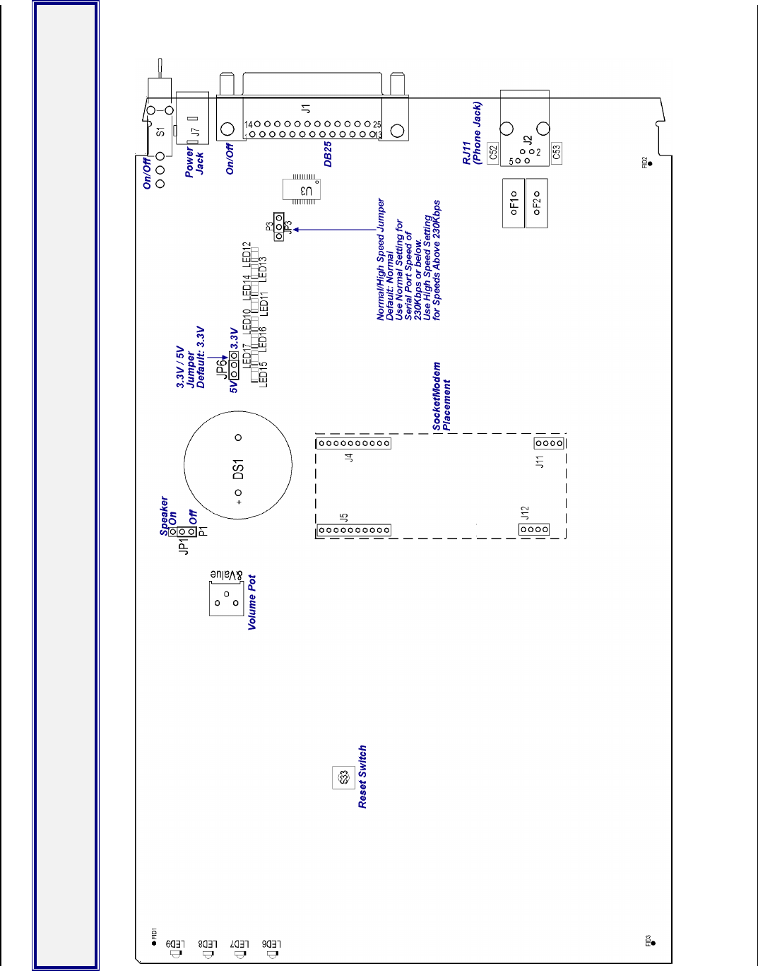
Appendix A – Mechanical Details
SocketModem Global MT5634SMI Developer’s Guide 76
Appendix A – Mechanical Details
Serial Test/Demo Board Components
Figure A–1. Serial Test/Demo Board
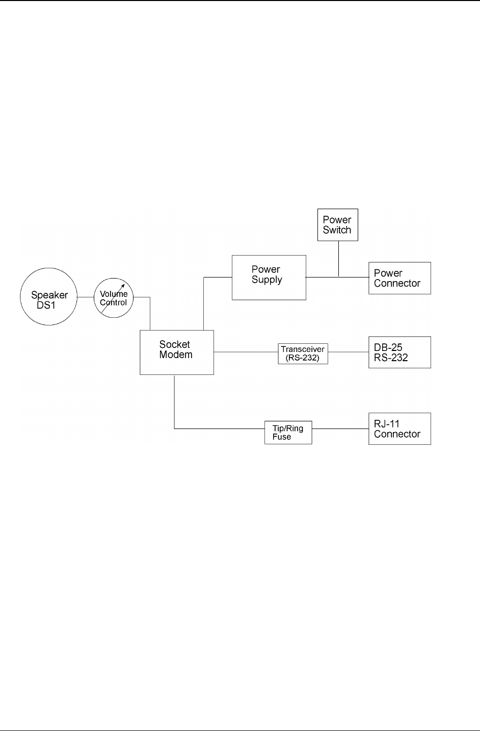
Appendix A – Mechanical Details
SocketModem Global MT5634SMI Developer’s Guide 77
5V / 3.3V Jumper – JP1
This JP1 Jumper provides for selection of either 5 volt or 3.3-volt operation.
Warning – Be sure to set the 5V/3.3V jumper to match the requirements of your SocketModem. If this jumper is
set incorrectly, damage to the SocketModem and/or the Test/Demo card could result.
Caution: Use only the provided Multi-Tech transformer with the Test/Demo board; use of any other power
source will void the warranty and will likely damage the Test/Demo board and SocketModem. The transformer
connector is keyed to prevent improper connection to the Test/Demo board.
Serial Test/Demo Board Block Diagram
Figure A–2. Serial Test/Demo Board Block Diagram
Caution: Use only the provided Multi-Tech transformer with the Test/Demo board; use of any other power
source will void the warranty and will likely damage the Test/Demo board and SocketModem. The transformer
connector is keyed to prevent improper connection to the Test/Demo board.
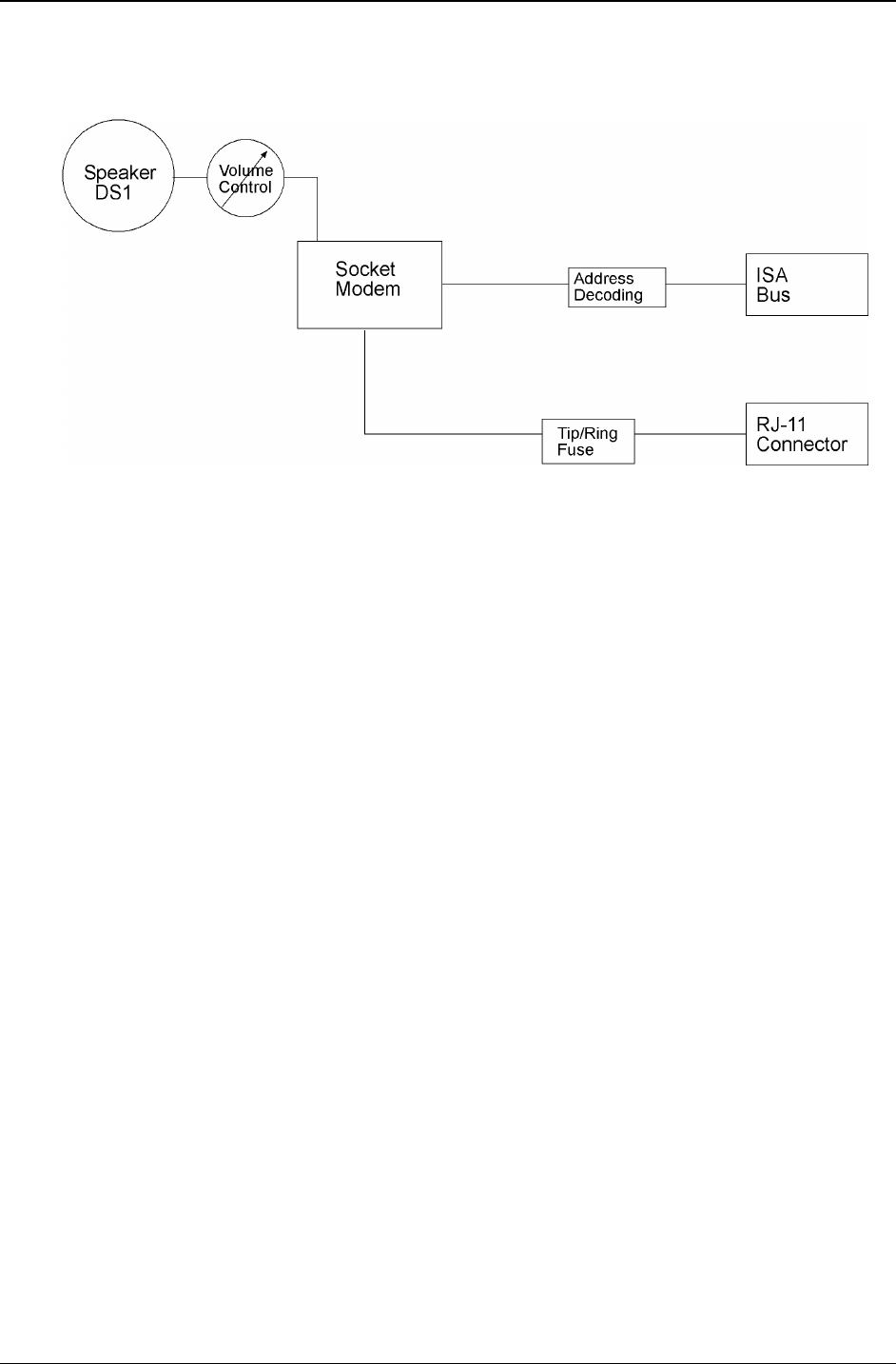
Appendix A – Mechanical Details
SocketModem Global MT5634SMI Developer’s Guide 78
Parallel Test/Demo Board Components
Figure A–4. Parallel Test/Demo Board
Interrupt (IRQ) Select Jumper – JP1
This JP1 Jumper is used to define the modem’s IRQ value by shorting a pair of pins together. The factory default
setting is IRQ 4 (pins 15 and 16)
I/O Address/COM Port/ IRQ Select Jumpers – JP2 and JP3
Jumpers JP2 and JP3 are used to define the modem’s I/O Address, COM Port, and IRQ selections. The factory
default setting is E, 3 (I/O Address. 3E8, COM Port 3, and IRQ 4).
Operating Voltage Select Jumper – JP4
The operating voltage factory default setting is 3.3V operation.

Appendix A – Mechanical Details
SocketModem Global MT5634SMI Developer’s Guide 79
Parallel Test/Demo Board Block Diagram
Speaker
DS1
Modem
Module
RJ-11
Connector
ISA
Bus
Volume
Control
Tip/Ring
Fuse
Address
Decoding
Figure A–4. Parallel Test/Demo Board Block Diagram

Appendix B – Product Approvals, Design Considerations, Regulatory Information
SocketModem Global MT5634SMI Developer’s Guide 80
Appendix B - Product Approvals,
Design Considerations, and
Regulatory Information
Safety and EMC Approvals
Safety EMC
EN60950 EN55022
UL1950 FCC Part 15
IEC950 Canadian EMC
AS/NZ3260 EN55024
CCIB (China) GB4943, GB9254
TS-001
Telecom Approvals
While this modem can be configured for specific country operation, doing so DOES NOT constitute country
approval. This modem is not approved in or configured for operation in all countries. The following list is displays
the country approvals as of February 1, 2002.
This information can be deemed reliable, but is not guaranteed. All information is subject to change.
Contact your Multi-Tech Systems, Inc. sales representative or call the world headquarters at 800-328-9717.
Country Country
Argentina Russia
Australia Singapore
Austria Slovakia
Belgium South Korea
Brazil Spain
Canada Sweden
Chile Switzerland
China Taiwan
Cyprus Turkey
Denmark United Kingdom
Estonia United States
Finland
France
Germany
Greece
Hong Kong
Hungary
Iceland
Indonesia
Ireland
Italy
Japan
Liechtenstein
Luxembourg
Mexico
Netherlands
New Zealand
Norway
Philippines
Poland
Portugal
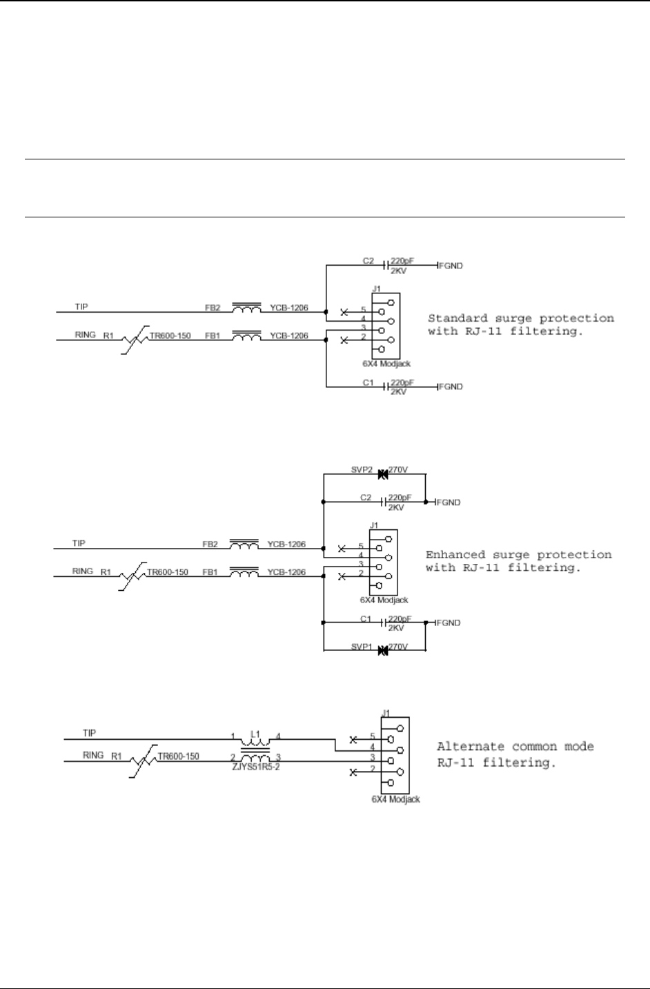
Appendix B – Product Approvals, Design Considerations, Regulatory Information
SocketModem Global MT5634SMI Developer’s Guide 81
Regulatory Design Considerations
This section discusses hardware considerations, PC board layout considerations, and Telecom labeling
requirements.
Hardware Considerations
Disclaimer: Multi-Tech Systems makes no warranty claims for vendor product recommendations listed
below. Other vendor products may or may not operate satisfactorily. Multi-Tech System’s recommended
vendor products only indicate that the product has been tested in controlled conditions and were found to
perform satisfactorily.
Figure B–1. Main Board Filtering

Appendix B – Product Approvals, Design Considerations, Regulatory Information
SocketModem Global MT5634SMI Developer’s Guide 82
EMC
Surface mount ferrites are used on T&R (Tip and Ring) to mitigate emission levels out the RJ-11 cable. 220pF
capacitors are also used on T&R to reduce the common mode emissions that may be present in certain systems.
The ferrite and capacitors also aid in reducing the effects of transients that may be present on the line.
Recommended Sidactor
Manufacturer – Teccor Electronics – Part # - P#3100SA
Manufacturer – ST Microelectronics -- Part 1 – SMP100-270
Recommended Ferrite (SMT)
Manufacturer – Associated Component Technology (ACT) – Part # - YCB-1206
Manufacturer – Murata Erie – Part # - BLM31A601SPT
Recommended Ferrite (Thru-Hole)
Manufacturer – Associated Component Technology (ACT) – Part # - WB2-2.OT
Recommended Capacitor
Manufacturer – Murata Erie – Part # - GHM3045X7R221K-GC (Surface mount device) and
Part # - DE0807B221K-KH (Thru-hole device)
Manufacturer – Ever Grace Electronic Industrials -- Part # - YP221K2EA7PS
Note: The capacitors used on T&R must have a Y2 safety rating.
Telecom
The RJ-11 connector must meet FCC Part 68 requirements. Refer to FCC Part 68 section 68.500 subpart F for
connector specifications. A self-healing fuse is used in series with line to help prevent damage to the DAA circuit.
This fuse is needed for FCC Part 68 compliance.
Recommended Connector
Manufacturer – Stewart – Part # - SS-6446-NF-A431
Recommended Fuse
Manufacturer – RayChem –Part # - TR600-150, TS600-170, or TS600-200
Note: The fuse is also needed to meet UL1950 3rd edition protection against over-voltage from power line
crosses.
Common Mode Choke
Manufacturer – TDK – Part # - ZJYS51R5 – 2PT
Safety
All creepages and clearances for the MT5634SMI have been designed to meet requirements of safety standards
EN60950 and IEC950. The requirements are based on a working voltage of 250V. When the recommended
DAA circuit interface is implemented in a third party design all creepage and clearance requirements must be
strictly adhered to. The third party safety design must be evaluated by the appropriate national agency per the
required specification.
User accessible areas: Based on where the third party design is to be marketed/sold or used, it may be
necessary to provide an insulating cover over all TNV exposed areas. Consult with the recognized safety agency
to determine the requirements.
Notice: Even if the recommended design considerations are followed, there are no guarantees that a particular
system will comply with all the necessary regulatory requirements. It is imperative that specific designs be
completely evaluated by a qualified/recognized agency.
Note: All safety notices must be added to any User Guide that you produce.
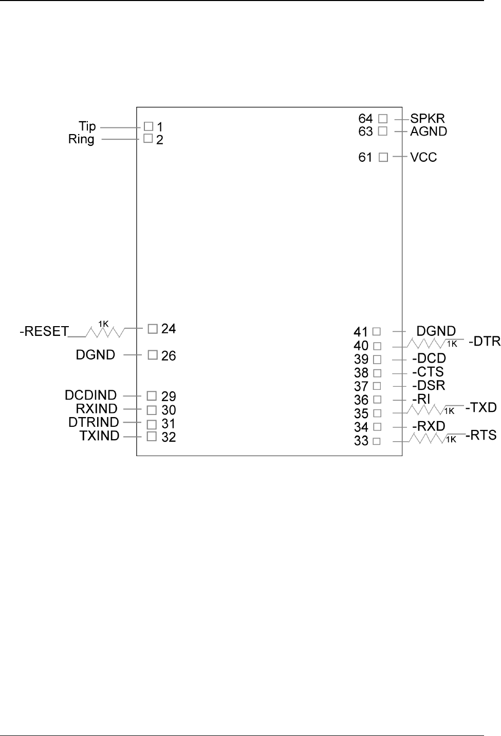
Appendix B – Product Approvals, Design Considerations, Regulatory Information
SocketModem Global MT5634SMI Developer’s Guide 83
5V Tolerant Inputs for 3.3V Modules
In order to drive the inputs of 3.3V modules from 5V logic, it is recommended to add a 1K series resistor to each
of the inputs: TXD, RTS, DTR, and RESET.

Appendix B – Product Approvals, Design Considerations, Regulatory Information
SocketModem Global MT5634SMI Developer’s Guide 84
FCC Part 15 Regulation
This equipment has been tested and found to comply with the limits for a Class B digital device, pursuant to Part
15 of the FCC rules. These limits are designed to provide reasonable protection against harmful interference in a
residential installation. This equipment generates, uses, and can radiate radio frequency energy, and if not
installed and used in accordance with the instructions, may cause harmful interference to radio communications.
However, there is no guarantee that interference will not occur in a particular installation. If this equipment does
cause harmful interference to radio or television reception, which can be determined by turning the equipment off
and on, the user is encouraged to try to correct the interference by one or more of the following measures:
Reorient or relocate the receiving antenna.
Increase the separation between the equipment and receiver.
Plug the equipment into an outlet on a circuit different from that to which the receiver is connected.
Consult the dealer or an experienced radio/TV technician for help.
This device complies with Part 15 of the FCC rules. Operation of this device is subject to the following conditions:
(1) This device may not cause harmful interference, and (2) this device must accept any interference that may
cause undesired operation.
WARNING – Changes or modifications to this unit not expressly approved by the party responsible for
compliance could void the user’s authority to operate the equipment.
Industry Canada
This Class B digital apparatus meets all requirements of the Canadian Interference-Causing Equipment
Regulations.
Cet appareil numérique de la classe B respecte toutes les exigences du Reglement Canadien sur le matériel
brouilleur.

Appendix B – Product Approvals, Design Considerations, Regulatory Information
SocketModem Global MT5634SMI Developer’s Guide 85
FCC Part 68 Telecom
1. This equipment complies with part 68 of the Federal Communications Commission Rules. On the outside
surface of this equipment is a label that contains, among other information, the FCC registration number.
This information must be provided to the telephone company.
2. The suitable USOC jack (Universal Service Order Code connecting arrangement) for this equipment is
shown below. If applicable, the facility interface codes (FIC) and service order codes (SOC) are shown.
3. An FCC-compliant telephone cord and modular plug is provided with this equipment. This equipment is
designed to be connected to the telephone network or premises wiring using a compatible modular jack that
is Part 68 compliant.
4. The ringer equivalence number (REN) is used to determine the number of devices that may be connected to
the telephone line. Excessive RENs on the telephone line may result in the device not ringing in response to
an incoming call. In most, but not all, areas the sum of the RENs should not exceed 5.0. To be certain of the
number of devices that may be connected to the line, as determined by the total RENs, contact the local
telephone company.
5. If this equipment causes harm to the telephone network, the telephone company will notify you in advance
that temporary discontinuance of service may be required. But if advance notice is not practical, the
telephone company will notify you as soon as possible. Also, you will be advised of your right to file a
complaint with the FCC if you believe it is necessary.
6. The telephone company may make changes in its facilities, equipment, operations, or procedures that could
affect the operation of the equipment. If this happens, the telephone company will provide advance notice in
order for you to make necessary modifications in order to maintain uninterrupted service.
7. If trouble is experienced with this equipment (the model of which is indicated below) please contact Multi-
Tech Systems, Inc. at the address shown below for details of how to have repairs made. If the trouble is
causing harm to the telephone network, the telephone company may request you remove the equipment
from the network until the problem is resolved.
8. No repairs are to be made by you. Repairs are to be made only by Multi-Tech Systems or its licensees.
Unauthorized repairs void registration and warranty.
9. This equipment should not be used on party lines or coin lines.
10. If so required, this equipment is hearing aid compatible.
Manufacturer: Multi-Tech Systems, Inc.
Trade Name SocketModem
Model Number: MT5634SMI
FCC Registration No: AU7-USA-25814-M5-E
Ringer Equivalence: 0.3B
Modular Jack (USOC): RJ11C or RJ11W (single line)
Service Center in USA: Multi-Tech Systems, Inc.
2205 Woodale Drive
Mounds View, MN 55112
U.S.A.
(763) 785-3500
(763) 785-9874 Fax
Telecom Labeling Requirements
FCC regulations require labeling of registered Telephone and Data Terminal Equipment in accordance with Part 68
Subpart D. There are two options available for labeling of the device containing the MT5634SMI SocketModem.
The first option would be to use the registration number assigned to Multi-Tech Systems, Inc. by the FCC as
explained in Section 68.300 below and shown in the sample label. The second option would be for the customer to
submit applications for and use their own registration number that would be assigned by the FCC. This would
require a letter of authorization for reregistration written by Multi-Tech Systems, Inc. giving the customer permission
to reregister the product. The customer would also need to obtain and file the necessary documents and pay the
required fees to the FCC.
Similarly, Industry Canada requires labeling in accordance with CS-03 requirements. An Industry Canada label
should be attached to the final product as described in the Industry Canada CS-03 section below. A label can be
purchased from Multi-Tech or a label printing company available to you. A Multiple Listing (similar to FCC’s re-
registration) is also an option for Industry Canada labeling.

Appendix B – Product Approvals, Design Considerations, Regulatory Information
SocketModem Global MT5634SMI Developer’s Guide 86
From FCC PART 68 Subpart D – Conditions for Registration
Complete document available from US Government Printing Office:
http://www.access.gpo.gov/cgi-bin/cfrassemble.cgi?title=199847
Section 68.300 Labeling requirements.
(a) Registered terminal equipment and registered protective circuitry shall have prominently displayed on an
outside surface the following information in the following format:
Complies With Part 68, FCC Rules
FCC Registration Number: _____________
Ringer Equivalence: ____
(b) Registered terminal equipment and registered protective circuitry shall also have the following identifying
information permanently affixed to it.
(1) Grantee’s name.
(2) Model number, as specified in the registration application.
(3) Serial number or date of manufacture.
(4) Country of origin of the equipment: “Made in __________.”
Required if the equipment is not manufactured in the United States. (Country of origin shall be determined
in accordance with 19 U.S.C. 1304 and regulations promulgated thereunder.)
(5) As used herein, permanently affixed means that the required nameplate data is etched, engraved,
stamped, indelibly printed or otherwise permanently marked. Alternatively, the required information may
be permanently marked on a nameplate of metal, plastic, or other material fastened to the enclosure by
welding, riveting, or with a permanent adhesive. Such a nameplate must be able to last for the expected
lifetime of the equipment and must not be readily detachable.
(6) When the device is so small or for such use that it is not practical to place the statements specified in this
section on it, the information required by paragraphs (a) and (b) of this section shall be placed in a
prominent location in the instruction manual or pamphlet supplied to the user. The FCC Registration
Number and the Model Number shall be displayed on the device.
Reregistration
(From Form 730 Application Guide Appendix C-2) http://www.fcc.gov/formpage.html
Private label distributors may obtain a registration number in their own name. In this case, a reregistration filing
is made with the submission of Exhibit B, a copy of a letter from the original registrant to the applicant giving
permission for the reregistration and a willingness to provide the applicant with any technical support. The
applicant will replace the registration label on the original grantee with the one containing the newly assigned
registration number.

Appendix B – Product Approvals, Design Considerations, Regulatory Information
SocketModem Global MT5634SMI Developer’s Guide 87
Fax Branding Statement
The Telephone Consumer Protection Act of 1991 makes it unlawful for any person to use a computer or other
electronic device, including fax machines, to send any message unless such message clearly contains the
following information:
Date and time the message is sent
Identification of the business or other entity, or other individual sending the message
Telephone number of the sending machine or such business, other entity, or individual
This information is to appear in a margin at the top or bottom of each transmitted page or on the first page of the
transmission. (Adding this information in the margin is referred to as fax branding.)
Since any number of fax software packages can be used with this product, the user must refer to the fax
software manual for setup details. Typically the fax branding information must be entered via the configuration
menu of the software.
Canadian Limitations Notice
Notice: The ringer equivalence number (REN) assigned to each terminal device provides an indication of the
maximum number of terminals allowed to be connected to a telephone interface. The termination on an interface
may consist of any combination of devices subject only to the requirement that the sum of the ringer equivalence
numbers of all the devices does not exceed 5.
Notice: The Industry Canada label identifies certified equipment. This certification means that the equipment
meets certain telecommunications network protective, operational, and safety requirements. The Industry
Canada label does not guarantee the equipment will operate to the user’s satisfaction.
Before installing this equipment, users should ensure that it is permissible to be connected to the facilities of the
local telecommunications company. The equipment must also be installed using an acceptable method of
connection. The customer should be aware that compliance with the above conditions may not prevent
degradation of service in some situations. Repairs to certified equipment should be made by an authorized
Canadian maintenance facility designated by the supplier. Any repairs or alterations made by the user to this
equipment or equipment malfunctions may give the telecommunications company cause to request the user to
disconnect the equipment.
Users should ensure for their own protection that the electrical ground connections of the power utility, telephone
lines and internal metallic water pipe system, if present, are connected together. This precaution may be
particularly important in rural areas.
Caution: Users should not attempt to make such connections themselves, but should contact the appropriate
electric inspection authority, or electrician, as appropriate.

Appendix B – Product Approvals, Design Considerations, Regulatory Information
SocketModem Global MT5634SMI Developer’s Guide 88
Industry Canada CS-03
Canadian regulations require that certified equipment bear an identifying certification label, which is obtained
from Industry Canada. The label provided must be displayed on the equipment according to Industry Canada
specifications. http://spectrum.ic.gc.ca/~cert/
From Certification Procedure 01 (CP-01):
Certified equipment will bear an identifying certification label and the certificate holder will be responsible for
permanently affixing this certification label. The certification label identifies certified equipment to the public,
representatives of the telecommunications common carriers, the Department, and other interested parties. The
label must be permanently affixed to the equipment.
Multiple Listing
This terminal device may be multiple listed to other distributors based upon the approval granted to the original
certificate holder. In order to obtain a multiple listing certification, the following documentation must be presented
to Industry Canada:
(a) The model number, Industry Canada certificate number and certification number of the approved equipment;
(b) A letter from the original certificate holder authorizing the Department to use information on file to grant a
multiple listing certification. The name/model number, certificate number and certification number for the
subject equipment must be shown. The letter must also declare that the model to be multiple listed is
identical in design and construction to the originally approved model;
(c) A letter, from the proposed multiple listee, requesting the certification;
(d) A Terminal Equipment Certification / Testing Application and Agreement form, completed by the proposed
multiple listee;
(e) A drawing, sample or illustration of the product label; and
(f) Payment in accordance with TRC-49 section on Multiple Listings.
International Modem Restrictions
Some dialing and answering defaults and restrictions may vary for international modems. Changing settings may
cause a modem to become non-compliant with national telecom requirements in specific countries. Also note
that some software packages may have features or lack restrictions that may cause the modem to become non-
compliant.
EMC, Safety, and R&TTE Directive Compliance
The CE mark is affixed to this product to confirm compliance with the following European Community Directives:
· Council Directive 89/336/EEC of 3 May 1989 on the approximation of the laws of Member States relating to
electromagnetic compatibility;
and
· Council Directive 73/23/EEC of 19 February 1973 on the harmonization of the laws of Member States relating
to electrical equipment designed for use within certain voltage limits;
and
· Council Directive 1999/5/EC of 9 March on radio equipment and telecommunications terminal equipment and
the mutual recognition of their conformity.

Appendix B – Product Approvals, Design Considerations, Regulatory Information
SocketModem Global MT5634SMI Developer’s Guide 89
New Zealand Telecom Warning Notice
1. The grant of a Telepermit for any item of terminal equipment indicates only that Telecom has accepted that
the item complies with minimum conditions for connection to its network. It indicates no endorsement of the
product by Telecom, nor does it provide any sort of warranty. Above all, it provides no assurance that any
item will work correctly in all respects with another item of Telepermitted equipment of a different make or
model, nor does it imply that any product is compatible with all of Telecom’s network services.
This equipment is not capable under all operating conditions of correct operation at the higher speed which it
is designated. 33.6 kbps and 56 kbps connections are likely to be restricted to lower bit rates when
connected to some PSTN implementations. Telecom will accept no responsibility should difficulties arise in
such circumstances.
2. Immediately disconnect this equipment should it become physically damaged, and arrange for its disposal or
repair.
3. This modem shall not be used in any manner, which could constitute a nuisance to other Telecom
customers.
4. This device is equipped with pulse dialing, while the Telecom standard is DTMF tone dialing. There is no
guarantee that Telecom lines will always continue to support pulse dialing.
Use of pulse dialing, when this equipment is connected to the same line as other equipment, may give rise
to ‘bell tinkle’ or noise and may also cause a false answer condition. Should such problems occur, the user
should not contact the Telecom Faults Service.
The preferred method of dialing is to use DTMF tones, as this is faster than pulse (decadic) dialing and is
readily available on almost all New Zealand telephone exchanges.
5. Warning Notice: No ‘111’ or other calls can be made from this device during a mains power failure.
6. This equipment may not provide for the effective hand-over of a call to another device connected to the
same line.
7. Some parameters required for compliance with Telecom’s Telepermit requirements are dependent on the
equipment (PC) associated with this device. The associated equipment shall be set to operate within the
following limits for compliance with Telecom’s Specifications:
For repeat calls to the same number:
· There shall be no more than 10 call attempts to the same number within any 30-minute period for
any single manual call initiation, and
· The equipment shall go on-hook for a period of not less than 30 seconds between the end of one
attempt and the beginning of the next attempt.
For automatic calls to different numbers:
· The equipment shall be set to ensure that automatic calls to different numbers are spaced such
that there is no less than 5 seconds between the end of one call attempt and the beginning of
another.
· For automatically answered incoming calls:
· The equipment shall be set to ensure that calls are answered between 3 and 30 seconds of receipt
of ringing.
8. For correct operation, total of the RN’s of all devices connected to a single line at any time should not
exceed 5.
South African Notice
This modem must be used in conjunction with an approved surge protection device.

Appendix C – Country Configuration and Result Codes
SocketModem Global MT5634SMI Developer’s Guide 90
Appendix C – Country Configuration
and Result Codes
This information is supplied to illustrate Multi-Tech’s country configurations. However, many of these countries are
not approved at this point in time. See Appendix B or contact your Multi-Tech sales representative regarding the
latest approvals.
Country Country Config. (hex) ATI9 Response
Afghanistan
Albania
Algeria
American Samoa
Andorra
Angola
Anguilla
Antarctica
Antigua & Barbuda
at%t19,0,34
at%t19,0,34
at%t19,0,34
at%t19,0,34
at%t19,0,34
at%t19,0,34
at%t19,0,34
at%t19,0,34
at%t19,0,34
52
52
52
52
52
52
52
52
52
Argentina at%t19,0,34 52
Armenia
Aruba
at%t19,0,34
at%t19,0,34
52
52
Australia at%t19,0,1 1
Austria at%t19,0,34 52
Azerbaijan
Bahamas
Bahrain
Bangladesh
Barbados
Belarus
at%t19,0,34
at%t19,0,34
at%t19,0,34
at%t19,0,34
at%t19,0,34
at%t19,0,34
52
52
52
52
52
52
Belgium at%t19,0,34 52
Belize
Benin
Bermuda
Bhutan
Bolivia
Bosnia & Herzegowina
Botswana
Bouvet Island
at%t19,0,34
at%t19,0,34
at%t19,0,34
at%t19,0,34
at%t19,0,34
at%t19,0,34
at%t19,0,34
at%t19,0,34
52
52
52
52
52
52
52
52
Brazil at%t19,0,34 52
British Indian Ocean Territory
Brunei Darussalam
Bulgaria
Burkina Faso
Burundi
Cambodia
Cameroon
at%t19,0,34
at%t19,0,34
at%t19,0,34
at%t19,0,34
at%t19,0,34
at%t19,0,34
at%t19,0,34
52
52
52
52
52
52
52
Canada at%t19,0,34 52
Cape Verde
Cayman Islands
Central African Republic
Chad
at%t19,0,34
at%t19,0,34
at%t19,0,34
at%t19,0,34
52
52
52
52
Chile at%t19,0,34 52
China at%t19,0,34 52
Christmas Island
Cocos (Keeling) Islands
Colombia
Comoros
Congo
Cook Islands
Costa Rica
at%t19,0,34
at%t19,0,34
at%t19,0,34
at%t19,0,34
at%t19,0,34
at%t19,0,34
at%t19,0,34
52
52
52
52
52
52
52

Appendix C – Country Configuration and Result Codes
SocketModem Global MT5634SMI Developer’s Guide 91
Country Country Config. (hex) ATI9 Response
Cote D'Ivoire
Croatia
Cuba
Cyprus
Czech Republic
at%t19,0,34
at%t19,0,34
at%t19,0,34
at%t19,0,34
at%t19,0,25
52
52
52
52
37
Denmark at%t19,0,34 52
Djibouti
Dominica
Dominican Republic
East Timor
Ecuador
Egypt
El Salvador
Equatorial Guinea
Eritrea
Estonia
Ethiopia
Falkland Islands (Malvinas)
Faroe Islands
Fiji
at%t19,0,34
at%t19,0,34
at%t19,0,34
at%t19,0,34
at%t19,0,34
at%t19,0,34
at%t19,0,34
at%t19,0,34
at%t19,0,34
at%t19,0,34
at%t19,0,34
at%t19,0,34
at%t19,0,34
at%t19,0,34
52
52
52
52
52
52
52
52
52
52
52
52
52
52
Finland at%t19,0,34 52
France at%t19,0,34 52
France-Metropolitan
French Guiana
French Polynesia
French Southern Territories
Gabon
Gambia
Georgia
at%t19,0,34
at%t19,0,34
at%t19,0,34
at%t19,0,34
at%t19,0,34
at%t19,0,34
at%t19,0,34
52
52
52
52
52
52
52
Germany at%t19,0,34 52
Ghana
Gibraltar
at%t19,0,34
at%t19,0,34
52
52
Greece at%t19,0,34 52
Greenland
Grenada
Guadeloupe
Guam
Guatemala
Guinea
Guinea-Bissau
Guyana
Haiti
Heard and Mc Donald Islands
Honduras
at%t19,0,34
at%t19,0,34
at%t19,0,34
at%t19,0,34
at%t19,0,34
at%t19,0,34
at%t19,0,34
at%t19,0,34
at%t19,0,34
at%t19,0,34
at%t19,0,34
52
52
52
52
52
52
52
52
52
52
52
Hong Kong at%t19,0,30 48
Hungary at%t19,0,30 48
Iceland at%t19,0,34 52
India at%t19,0,30 48
Indonesia at%t19,0,30 48
Iran
Iraq
at%t19,0,34
at%t19,0,34
52
52
Ireland at%t19,0,34 52
Israel at%t19,0,30 48
Italy at%t19,0,34 52
Jamaica at%t19,0,34 52
Japan at%t19,0,10 16
Jordan
Kazakhstan
Kenya
Kiribati
Korea-Democratic People's Republic of
Korea-Republic of
Kuwait
Kyrgyzstan
at%t19,0,34
at%t19,0,34
at%t19,0,34
at%t19,0,34
at%t19,0,30
at%t19,0,34
at%t19,0,34
at%t19,0,34
52
52
52
52
48
52
52
52

Appendix C – Country Configuration and Result Codes
SocketModem Global MT5634SMI Developer’s Guide 92
Country Country Config. (hex) ATI9 Response
Lao People's Democratic Republic
Latvia
Lebanon
Lesotho
Liberia
Libyan Arab Jamahiriya
Liechtenstein
Lithuania
at%t19,0,34
at%t19,0,34
at%t19,0,34
at%t19,0,34
at%t19,0,34
at%t19,0,34
at%t19,0,34
at%t19,0,34
52
52
52
52
52
52
52
52
Luxembourg at%t19,0,34 52
Macau
Macedonian-Former Yugoslav Republic of
Madagascar
Malawi
Malaysia
Maldives
Mali
Malta
Marshall Islands
Martinique
Mauritania
Mauritius
Mayotte
at%t19,0,34
at%t19,0,34
at%t19,0,34
at%t19,0,34
at%t19,0,30
at%t19,0,34
at%t19,0,34
at%t19,0,34
at%t19,0,34
at%t19,0,34
at%t19,0,34
at%t19,0,34
at%t19,0,34
52
52
52
52
48
52
52
52
52
52
52
52
52
Mexico at%t19,0,34 52
Micronesia (Federated States of)
Moldavia -Republic of
Monaco
Mongolia
Montserrat
Morocco
Mozambique
Myanmar
Namibia
Nauru
Nepal
at%t19,0,34
at%t19,0,34
at%t19,0,34
at%t19,0,34
at%t19,0,34
at%t19,0,34
at%t19,0,34
at%t19,0,34
at%t19,0,34
at%t19,0,34
at%t19,0,34
52
52
52
52
52
52
52
52
52
52
52
Netherlands at%t19,0,34 52
Netherlands Antilles at%t19,0,34 52
New Caledonia at%t19,0,34 52
New Zealand at%t19,0,9 9
Nicaragua
Niger
Nigeria
Niue
Norfolk Island
Northern Mariana Islands
at%t19,0,34
at%t19,0,34
at%t19,0,34
at%t19,0,34
at%t19,0,34
at%t19,0,34
52
52
52
52
52
52
Norway at%t19,0,34 52
Oman
Pakistan
Palau
Panama
Papua New Guinea
Paraguay
Peru
Philippines
Pitcairn
at%t19,0,34
at%t19,0,34
at%t19,0,34
at%t19,0,34
at%t19,0,34
at%t19,0,34
at%t19,0,34
at%t19,0,30
at%t19,0,34
52
52
52
52
52
52
52
48
52
Poland at%t19,0,30 48
Portugal at%t19,0,34 52
Puerto Rico
Qatar
Reunion
Romania
Russian Federation
Rwanda
St. Helena
Saint Kitts and Nevis
at%t19,0,34
at%t19,0,34
at%t19,0,34
at%t19,0,34
at%t19,0,34
at%t19,0,34
at%t19,0,34
at%t19,0,34
52
52
52
52
52
52
52
52

Appendix C – Country Configuration and Result Codes
SocketModem Global MT5634SMI Developer’s Guide 93
Country Country Config. (hex) ATI9 Response
Saint Lucia
St. Pierre and Miquelon
Saint Vincent and the Grenadines
Samoa
San Marino
Sao Tome and Principe
Saudi Arabia
Senegal
Seychelles
Sierra Leone
at%t19,0,34
at%t19,0,34
at%t19,0,34
at%t19,0,34
at%t19,0,34
at%t19,0,34
at%t19,0,34
at%t19,0,34
at%t19,0,34
at%t19,0,34
52
52
52
52
52
52
52
52
52
52
Singapore at%t19,0,30 48
Slovakia at%t19,0,34 52
Slovenia
Solomon Islands
Somalia
South Africa
South Georgia and the South Sandwich
Islands
at%t19,0,30
at%t19,0,34
at%t19,0,34
at%t19,0,35
at%t19,0,34
at%t19,0,34
48
52
52
53
52
52
Spain at%t19,0,34 52
Sri Lanka
Sudan
Suriname
Svalbard and Jan Mayen Islands
Swaziland
at%t19,0,34
at%t19,0,34
at%t19,0,34
at%t19,0,34
at%t19,0,34
52
52
52
52
52
Sweden at%t19,0,34 52
Switzerland at%t19,0,34 52
Syrian Arab Republic
Taiwan-Province of China
Tajikistan
Tanzania-United Republic of
Thailand
Togo
Tokelau
Tonga
Trinidad and Tobago
Tunisia
Turkey
Turkmenistan
Turks and Caicos Islands
Tuvalu
Uganda
Ukraine
United Arab Emirates
at%t19,0,34
at%t19,0,34
at%t19,0,34
at%t19,0,34
at%t19,0,34
at%t19,0,34
at%t19,0,34
at%t19,0,34
at%t19,0,34
at%t19,0,34
at%t19,0,34
at%t19,0,34
at%t19,0,34
at%t19,0,34
at%t19,0,34
at%t19,0,34
at%t19,0,34
52
52
52
52
52
52
52
52
52
52
52
52
52
52
52
52
52
United Kingdom at%t19,0,34 52
United States at%t19,0,34 52
United States Minor Outlying Islands
Uruguay
Uzbekistan
Vanuatu
Vatican City State (Holy See)
Venezuela
Vietnam
Virgin Islands (British)
Virgin Islands (U.S.)
Wallis and Futuna Islands
Western Sahara
Yemen
Yugoslavia
Zaire
Zambia
Zimbabwe
at%t19,0,34
at%t19,0,34
at%t19,0,34
at%t19,0,34
at%t19,0,34
at%t19,0,34
at%t19,0,30
at%t19,0,34
at%t19,0,34
at%t19,0,34
at%t19,0,34
at%t19,0,34
at%t19,0,34
at%t19,0,34
at%t19,0,34
at%t19,0,34
52
52
52
52
52
52
48
52
52
52
52
52
52
52
52
52

Appendix D – SocketModem and the New SerialModule
SocketModem Global MT5634SMI Developer’s Guide 94

Appendix D – SocketModem and the New SerialModule
SocketModem Global MT5634SMI Developer’s Guide 95
Index
5
56K operation
digital loss when used with PBX, 41
A
Abort timer, 40
Adaptive Answer Result Code Enable command, 31
Answer command, 25
Asynchronous Communications Mode command, 28
Asynchronous Word Length command, 32
AT Command Control command, 31
AT commands, 23
#CBA, 33, 38
#CBD, 33, 38
#CBF?, 33, 39
#CBFR, 33, 39
#CBI, 33, 39
#CBN=, 33, 39
#CBP, 33, 39
#CBR, 34, 39
#CBS, 34, 39
#P, 34, 39
#S, 34, 39, 67
#S=, 34, 39, 67
$D, 32
$EB, 32
$MB, 32
$RP, 32
$SB, 32
%A, 31
%B, 31
%C, 31
%DC, 31
%E, 31
%H, 31
%R, 31
%S, 32
&C, 27
&D, 28
&E, 28
&F, 28
&G, 28
&K, 28
&L, 28
&P, 28
&Q, 28
&S, 29
&T, 29
&V, 29
&W, 67, 68
&Y, 29
&Z=, 29
+++AT, 34
+FCLASS= <mode>, 46
+FCLASS=8, 47
+FLO=<method>, 48
+FMI?, 48
+FMM?, 48
+FMR?, 48
+MS?, 35
+MS=, 35
+MS=?, 35
+PCW=, 36
+PIG=, 36
+PMH=, 36
+PMHF, 37
+PMHR=, 37
+PMHT=, 37
+PQC=, 38
+VBT=, 57
+VBT=?, 57
+VCID=, 38
+VDR=, 55
+VDR=, 33, 38
+VDT=, 55
+VEM=, 56
+VEM=?, 56
+VGR=<gain>, 50
+VGT=<level>, 51
+VIT=<timer>, 51
+VLS=?, 52
+VLS=<label>, 51
+VNH=<hook>, 48
+VPP=, 57
+VPR=, 58
+VRA=<interval>, 52
+VRN=<interval>, 53
+VRX, 49
+VSD=<sds>,<sdi>, 53
+VSM=, 53
+VSM=?, 54
+VTD=, 55
+VTS=?, 50
+VTS=<string>, 49
+VTX, 50
\A, 29
A, 25
A/, 25
AT, 25
AT+FCLASS=?, 47
\B, 29
B, 25
-C, 31
D, 25
definition, 23
disabling response to, 31
DS=, 25
E, 26
F, 26
format, 23
H, 26
I, 26

Index
SocketModem Global MT5634SMI Developer’s Guide 96
\K, 30
M, 26
\N, 30
N, 26
O, 26, 67, 68
P, 26
\Q, 30
Q, 26
Sr?, 27
Sr=, 27
\T, 30
T, 27
\V, 30, 31
V, 27
VIP, 48
W, 27
X, 27
Z, 27
Attention code command, 25
Autoanswer, 23, 40
Automatic Hang-Up Control command, 48
B
Backspace character, setting, 40
Bell 212A mode, 25
Blacklist command, 31
Break Control command, 30
Break signal, 30
C
call waiting, 36
Call Waiting Enable command, 36
Callback Attempts command, 33, 38
Callback Delay command, 33, 38
Callback Enable/Disable command, 34, 39
Callback Failed Attempts Display command, 33, 39
Callback Failed Attempts Reset command, 33, 39
Callback Parity command, 33, 39
callback security
callback attempts, 38
callback delay time, 38
enabling and disabling, 34, 39
failed password attempts, 39
inactivity timer, 39
parity, 33, 39
passwords, 33, 39
resetting failed attempts, 39
setup password, 39
types of, 34, 39
Callback Security Reset command, 34
callback security settings, 29
Caller ID, 38
Caller ID Selection command, 38
Canadian Limitations Notice, 87
Canadian regulation requirements, 88
Carriage return character, 40
Carrier loss disconnect time, setting, 40
Cisco Configuration command, 31
Comma, setting pause time, 40
Command mode, 23
Command Speed Response command, 32
Command string, 23
Communication Standard command, 25
Communications programs, 23
configuration
Country Code, 68
Global Wizard, 68
remote, 67
Configuration
Selecting reset configuration command, 29
Control Tone Cadence Reporting command, 55
Country Code, 68
Country code, displaying, 26
Country Configuration/Result Codes Chart, 90
creepages and clearances, 82
D
Data buffering, 28
Data Calling Tone command, 31
Data Carrier Detect command, 27
Data Compression Control command, 31
Data mode, 23, 26
Data Set Ready Control command, 29
Data Terminal Ready Control command, 28
DCD Control command, 27
Design considerations
Vendor recommendations, 81
Diagnostic information, displaying, 26
Dial command, 25
Dial Stored Telephone Number command, 25
Dial string modifiers, 25
Dialing tones, 40
Direct Connect Enable command, 31
Disconnect delay, 40
Display Current Settings command, 29
Display Service Class Capabilities command, 47
Distinctive Ring command, 38
Distinctive Ring Report command, 33
DSR Control command, 29
DTE/DCE Interface Rates, 65
DTMF Detect Detect and Control DTMF command, 47
DTR Control command, 28
DTR Dialing command, 32
E
Echo Command Mode Characters command, 26
Echo Online Data Characters command, 26
Electrical Characteristics, 14
EMC, Safety, and R&TTE Directive Compliance, 88
Enable or Disable Voice Mode Packet Protocol
command, 57
Enable/Disable Distinctive Ring (Ring Cadence
Reporting) command, 55
ENTER key, 25
Enter Setup Password command, 34, 39
Enter Voice Receive State command, 49
Error control, setting, 40, 41
Error Correction Mode Selection command, 30
Escape AT Commands, 34
Escape character, 40
Escape sequence, 23, 34
Event Reporting and Masking command, 56

Index
SocketModem Global MT5634SMI Developer’s Guide 97
F
Fallback, 26
Fallback and Fall Forward command, 31
Fax Branding Statement, 87
Fax commands, 66
FCC Regulations, 85
Features Matrix, 7
Firmware Upgrade Procedure, 69
Firmware version, displaying, 26
flash, 37
Flash Upgrade, 69
Flow control, 30
Flow Control, 58
Flow Control Selection command, 28, 30
G
Global Wizard, 68
Guard Tone Control command, 28
H
Handling Precautions, 15
Handshake, 26
Hangup command, 26
Hangup delay, 40
Hook Control command, 26
I
Identify Analog Source/Destination Configuration and
Event Reporting Capabilities command, 52
Inactivity timer, 40
Inactivity Timer command, 30
Information Request command, 26
Initialization strings, 23
Initialize Voice Parameters command, 48
Interface Configuration Commands, 57
Internal Registers, 16, 18
International Modem Restrictions, 88
L
Leased Line Operation command, 28
Line feed character, 40
Load Factory Settings command, 28
Local Callback Inactivity Timer command, 33, 39
Loopback Test commands, 29
M
MNP 5 data compression, 31
MNP error correction, 30
Modem on Hold, 36, 37
Modem on Hold Enable command, 36
Modem on Hold Initiate command, 37
Modem on Hold Timer command, 37
Modem Reset command, 27
Modulation Handshake command, 26
Modulation Selection command, 35
Monitor Speaker Mode command, 26
N
New Zealand Telecom Warning Notice, 89
O
On-hook/off-hook, 26
Online BPS Speed command, 32
Online command mode, 23
P
Parallel Test Board Components, 78
parity, setting, 34, 39
Pause time for comma, setting, 40
PCM Upstream Ignore command, 36
Produce DTMF and Tone Generation in Voice Mode
command, 49
Protocol Result Code command, 30, 31
Pulse Dial Make-to-Break Ratio Selection command,
28
Pulse Dialing command, 26
Q
Quick Connect, 38
Quick Connect Control command, 38
R
Rate, maximum data, 40
Read Register Value command, 27
Remote configuration, 67
Escape character, 40, 68
Remote escape character, changing, 68
Repeat Last command, 25
Report Event Reporting and Masking Capabilities
command, 56
Report Frequency Support command, 50
Report Manufacturer’s ID command, 48
Report Modem Flow Control Assert and Deassert
Points command, 57
Report Product ID command, 48
Report Version Level command, 48
Report Voice Compression Method command, 54
Resetting the modem, 27, 28
Result Code Format command, 27
Result Code Options command, 27
Result Code Selection command, 27
Result codes, 23
Result Codes, 42
Result Codes Enable/Disable command, 26
Return Online to Data Mode command, 26
Ring Priority vs. AT Command Priority Command, 32
Rings, setting number of, 40
ROM checksum, 26
S
Safety considerations, 82
Select Analog Source/Destination command, 51
Select Default Beep Tone Duration Timer
(DTMF/Tone Generation Duration) command, 55

Index
SocketModem Global MT5634SMI Developer’s Guide 98
Select DTE/DCE Interface Rate (Turn Off Autobaud)
command, 58
Select Flow Control Method command, 48
Select Maximum MNP Block Size command, 29
Select Modem Operating Mode command, 46
Select Stored Configuration command, 29
Select Voice Compression Method command, 53
Serial Port Baud Rate command, 32
servicing your modem, 85
Set 11-bit Parity command, 34, 39
Set DTE/DCE Inactivity Timer command, 51
Set Modem Flow Control Assert and Deassert Points
command, 57
Set Register Value command, 27
Set Ring Back Goes Away Timer command, 52
Set Ring Back Never Appeared Timer command, 53
Set Silence Detection Sensitivity command, 53
Set the Gain for Received Voice Samples command,
50
Set the Volume for Transmitted Voice Samples
command, 51
Setup password, 67
Setup password, changing, 67
sleep mode, 41
Speaker Mode command, 26
Specifications
technical, 8
Speed
Maximum, 40
Speed conversion (data buffer), 28
S-registers, 40
reading, 27
S0, 40
S1, 40
S10, 40
S108, 41
S11, 40
S2, 40
S28, 40
S3, 40
S30, 40
S35, 40
S36, 40
S37, 40
S38, 41
S4, 40
S43, 41
S48, 41
S5, 40
S6, 40
S7, 40
S8, 40
S89, 41
S9, 40, 68
setting, 27
Standby mode delay time, 41
Start Voice Transmission Process command, 50
Store Callback Password command, 33, 39
Store Dialing command, 29
Store Setup Password command, 34, 39
T
Technical specifications, 8
Telecom Approvals, 80
Telecom Labeling Requirements, 85
Timing Requirements, 15
Tone Dialing command, 27
Tones, dialing, 40
Transmit Break command, 29
U
upstream mode, 36
Upstream V.90 data rates, 41
V
V.22 mode, 25
V.22bis Guard Tone Control command, 28
V.25 data calling tone, 31
V.34 modulation, enabling, 40
V.42 error correction, 30
V.42bis data compression, 31
V.54 Test commands, 29
V.92 mode, 35, 36, 37, 38
V.92 Modem Hook Flash command, 37
View Numbers in Blacklist command, 31
Voice Commands, 44
Voice Mode Result Codes, 58
Voice Mode Result Codes, 59
Voice Mode Shielded Codes, 60
Voice Sample Sessions, 62
W
Wait time for dial tone, 40
warranty, 85
X
XON/XOFF Pacing Control, 28
