Technisonic P2088A P2088A-Q806AZ-H35BM User Manual P25 Manual
Technisonic Industries Limited P2088A-Q806AZ-H35BM P25 Manual
Users manual

MULTIBAND P25
AIRBORNE TRANSCEIVER
MODEL TDFM-600/6000
Installation and
Operating Instructions
Til Document No.
01RE293
Rev.
January 23 / 2002
Technisonic Industries Limited
250 Watline Avenue, Mississauga, Ontario L4Z 1P4 Tel:(905)890-2113 Fax:(905)890-5338
3840 East Robinson Road, Suite 214, Amherst, New York 14228 Tel:(716)691-0669
CAUTION
This unit contains static sensitive devices. Wear a grounded wrist strap and/or conductive gloves when handling
printed circuit boards.
WARNING: This device complies with Part 15 of the FCC Rules. Operation is subject to the following two conditions:
(1) this device may not cause harmful interference and (2) this device must accept any interference
received, including interference that may cause undesired operation.
NOTE: This equipment has been tested and found to comply with the limits for a
Class A digital device, pursuant to Part 15 of the FCC Rules. These limits are
designed to provided reasonable protection against harmful interference
when the equipment is operated in a commercial environment. This
equipment generates, uses, and can radiate radio frequency energy and, if
not installed and used in accordance with the instruction manual, may cause
harmful interference to radio communications. Operation of this equipment in
a residential area is likely to cause harmful interference in which case the
user will be required to correct the interference at his own expense.
Warning:
Changes or modifications not expressly approved by Technisonic Industries could void
the user=s authority to operate the equipment.
WARRANTY INFORMATION
The Model TDFM-600/6000 Transceiver is under warranty for one year from date of purchase. Failed units
caused by defective parts, or workmanship should be returned to:
Technisonic Industries Limited Technisonic Industries Limited
250 Watline Avenue 3840 E. Robinson Road, Suite 214
Mississauga, Amherst,
Ontario L4Z 1P4 New York 14228
Tel: (905) 890-2113 Fax: (905) 890-5338 Tel: (716) 691-0669
A Page
WARNING For compliance with FCC RF Exposure Requirements, the mobile
transmitter antenna installation shall comply with the following two
conditions:
1. The transmitter antenna gain shall not exceed 3 Bi
2. The transmitter antenna is required to be located outside of a vehicle and kept at a separation distance of
70 cm meters or more between the transmitter antenna of this device and persons during operation.
TABLE OF CONTENTS
Paragraph Title Page
SECTION 1 GENERAL DESCRIPTION
1.1 Introduction..............................................................................................................1-1
1.2 Description ..............................................................................................................1-1
1.3 Technical Summary..................................................................................................1-1
SECTION 2 OPERATING INSTRUCTIONS
2.1 General ...................................................................................................................2-1
2.14 Radio Service Software .............................................................................................2-4
SECTION 3 INSTALLATION INSTRUCTIONS
3.1 General ...................................................................................................................3-1
3.2 Equipment Packing Log............................................................................................3-1
3.3 Transceiver Installation..............................................................................................3-1
3.4 Installation Kit - Contents..........................................................................................3-1
3.5 Pin Locations and Connections..................................................................................3-2
3.6 Wiring Instructions....................................................................................................3-3
LIST OF TABLES
Table No. Title Page
3-1 25-pin D Connections................................................................................................3-2
LIST OF ILLUSTRATIONS
Figure No. Title Page
3-1 Outline Drawing........................................................................................................3-1
3-2 Wiring Connections and notes ...................................................................................3-5

1-1
SECTION 1
GENERAL DESCRIPTION
1.1 INTRODUCTION
This publication provides operating and installation information on the TDFM-600/6000 airborne
transceiver. (The exact model number depends on which and how many RF modules are installed.)
1.2 DESCRIPTION
The TDFM-600/6000 series of transceivers are airborne multiband radios capable of conventional FM,
P25, Smartnet and Smartzone trunking systems and any other feature supported by the Motorola XTS-
3000 portable radio. The modules are available in VHF, UHFLO, UHFHI and 800 MHz bands. The bands
are numbered 1,4,5 and 8 respectively.
TDFM-655 -Two UHF high band modules
TDFM-688 -Two 800 MHz modules
TDFM-6148 -One VHF, UHF low and 800 MHz module
TDFM-6158 -One VHF, UHF high and 800 MHz module
1.3 TECHNICAL CHARACTERISTICS
Specification Characteristic
Model Designation: TDFM-600/6000
Physical Dimensions: Approx. 8" X 3" X 5.75"
Weight: 3 Lbs (1.2 kg)
Operating Temperature Range: -45ΕC to +60ΕC
Power Requirement:
Voltage: 28.0 Vdc, ∀ 15%
Current: 165mA minimum
5A maximum
RF Output Power: 1 or 5 Watts
Frequency Range - VHF Module: 136 to 178 MHz
UHF LO Module: 403 to 470 MHz
UHF HI Module: 450 to 512 MHz
800 Module: 806 to 870 MHz
Audio Output Power (including sidetone): 500 mW into 600 ohms
Microphone Inputs: Carbon or Equivalent
Panel Back Lighting: 28 VDC or 5VAC
(specified when ordered)
SECTION 2
2-2
OPERATING INSTRUCTIONS
2.1 GENERAL
The TDFM-600/6000 transceiver is designed to operate in the same fashion as the Motorola XTS-3000
portable radio. The display has been rearranged into a 2 line display from 4 and some of the numeric
keys also double as function keys. Two or three XTS-3000 RF modules are installed in the unit. The
display is showing the activity of one module at a time selected by pressing the desired knob. The
knobs have multiple functions including volume, channel, display dimmer. The microphone, key line and
headphone audio are separate for each of the two or three bands therefore switching from band to band
is performed at an audio panel. This allows for separate and simultaneous operation on each of the
bands just like having 2 or 3 separate radios.
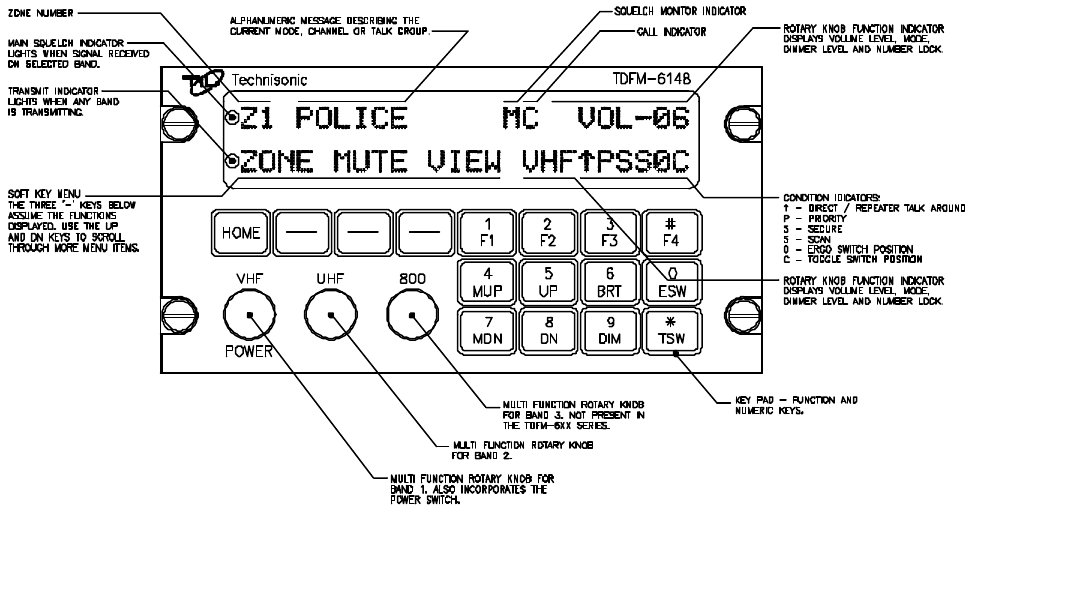
2.2 FRONT PANEL
Refer to the diagram below:
2.3 POWER SWITCH
To switch the transceiver on, press the left most knob. The transceiver will immediately power up. The
display will show ATECHNISONIC@ and the software version installed followed by the model number
as determined by which RF modules are installed. The display will then show the normal display for
band 1. To switch off the transceiver at any time, press and hold the left most knob for 2 seconds until
the display shows AOFF@ then release.
2.4 KNOBS
The transceiver will have two or three knobs depending on how many RF modules are installed. The

2-3
knobs are rotary encoders which turn endlessly which means their actual position is not important.
Each knob also has a push button incorporated in it so you can press the knob as well as turn it.
Pressing a different knob will cause the display and keyboard to switch to the band associated with that
knob. The knob will start out as a volume control. Pressing the same knob again will change its function
to act as the channel/talkgroup selector depending on how that band is programmed. Pressing the
same knob again changes the function of the knob to a display dimmer control. Pressing the knob
again causes the key pad function to change from function keys to number keys. The knob in this
mode acts as a volume control. Pressing the knob again brings it back to the first mode of volume
control. The current function of the knob is shown at the top right of the display. The function of the
knobs of the unselected bands are always volume control.
2.5 SOFT KEYS AND HOME
The transceiver has three Asoft@ keys which assume the function shown above them on the display.
The functions displayed depend on how the module was programmed with the radio service software
(RSS). Functions can be different on a channel by channel basis as well. These may include:
ZONE - Pressing this function will prompt you for a new zone number which can be entered
directly or scrolled using the UP and DN keys.
MUTE - Selecting this function will prompt you for an on or off entry using the soft keys. Tones
refer to the beeps heard when pressing buttons.
VIEW - The view function is used to view lists. Lists can include phone numbers, call lists and
or page.
CHAN - Pressing CHAN will prompt you for a new channel number. This can be entered via the
key pad or by using the UP and DN buttons. Channel selection can also be
programmed as one of the rotary knob functions using the RSS.
PWR - Selecting PWR will allow the power output of the radio to be set to high or low.
PROG - Selecting PROG allows brings you to user programmable features of the radio such
as telephone numbers. The ability for the user to program phone numbers, etc can be
enabled or disabled by the RSS.
At any time while in one of these functions, you can escape back to the normal mode by pressing the
HOME key.
2.6 FUNCTION KEYS
Four function keys at the top of the keypad provide the same actions as the three side buttons and the
top button found on the XTS-3000 portable. They are as follows:
F1 - Top side button (purple button) on the XTS-3000.
F2 - Center side button (with one dot) on the XTS-3000.
F3 - Bottom side button (with two dots) on the XTS-3000.
F4 - Top button (orange button) on the XTS-3000.
TDFM-600/6000 Transceiver Recommended Keypad Menu Defaults:

2-4
TDFM-600/6000
ITEM
XTS-3000
Portable
ITEM
Conventional
Operation (H35) Smart Net
Operation (H37) Smart Zone
Operation (H38)
F1 Key Top Side
Button 1 Monitor Phone Phone
F2 Key Center Side
Button 2 Scan Scan Scan
F3 Key Bottom Side
Button 3 Talkaround/
Direct Private Call Site
Display/Search
F4 Key Orange (Top)
Button Emergency Emergency Emergency
MUP and
MDN keys 16-Position
Rotary Knob Channel Select Channel Select Channel Select
ESW Key Two-Position
Concentric or
Ergo Switch
Blank ()
Low Power (ι)Blank ()
Low Power (ι)Blank ()
Low Power (ι)
TSW Key Three-Position
Toggle Switch Blank (A)
Scan (B)
Blank (C)
Blank (A)
Scan (B)
Blank (C)
Blank (A)
Scan (B)
Blank (C)
Note: It is possible to use Motorola=s Radio Service Software (RSS or CPS) to alter the default
keypad settings of the TDFM-600/6000 series radios. However if custom key settings are
chosen it will not be possible for Technisonic to help the Pilot or other Radio User through
operational difficulties. These questions will have to be referred to the Radio System
Administrator responsible for customising the settings. Technisonic recommends that the
default key settings stay in place until all airframe installation and operational issues have been
overcome.
The TDFM-600/6000 series Transceivers are programmable by Motorola Radio Service Software. The
following settings may be programmed for each Channel in a Conventional Radio:
Tx Frequency Zone
Tx PL/DPL Code Channel
Rx Frequency Name
Rx PL/DPL Code RX Signal Voice Type
Time-Out Timer TX Signal Voice Type
Scan List Network Access Code
Phone Tx Power
Smart PTT
The following settings must be programmed for each mode in a Trunked (Smart Net or Smart Zone)
Radio:
System Type TG Strapping
System ID Zone
Individual ID Scan List
2-5
Coverage Type Scan Type
Affiliation Type Interconnect
Control Channel 1 Phone Display Format
Control Channel 2 Private Call
Talkgroup 1 Private Call Type
Talkgroup 2 Private Call Operation
The function keys along with the rest of the key pad, revert to normal number keys during transmit and
when NUM LOCK is selected by pressing the rotary knob.
2.7 MUP AND MDN KEYS
These keys provide the same function as the rotary knob does when it is set to MODE. This equates
to the 16 position rotary knob on the XTS-3000. When one of these keys is pressed, the function of the
rotary knob is automatically set to MODE.
2.8 UP AND DN KEYS
The keys provide the same function as the left and right arrow keys on the XTS-3000. The UP key
equates to the right arrow key. These keys are used for a variety of functions but in the normal mode
they are used to scroll through the soft key menus.
2.9 BRT AND DIM KEYS
Use these keys to dim or brighten the display. The radio powers up at full brightness for normal use but
can be dimmed for night operations.
2.10 ESW KEY
The ESW key provides the function of the concentric or >ergo= switch on the XTS-3000. The switch
has two conditions which are represented by >o= and >ι=. Pressing the ESW key toggles the condition
back and forth. The condition is displayed at the bottom of the display, second character from the right.
The ergo switch condition is saved when the unit is turned off. There are separate conditions for each
band installed. The ESW key can be programmed with the RSS to a variety of functions such as low
power, scan, channel, and secure mode.
2.11 TSW KEY
The TSW key provides the function of the toggle switch on the XTS-3000. The switch has three
conditions which are represented by >A=,=B= and >C=. Pressing the TSW key toggles the condition
A,B,C,A,B, etc. The condition is displayed at the bottom of the display, last character on the right. The
toggle switch condition is saved when the unit is turned off. There are separate conditions for each band
installed. The TSW key can be programmed with the RSS to a variety of functions such as low power,
scan, channel, and secure mode.
2.12 DISPLAY
The transceiver has a two line, 48 character LED display which gives information about the selected
band. On the top line is shown the zone number, channel name and rotary knob function. The bottom
line displays the soft key menu, the band selected, and the ESW/TSW condition. Also displayed are
letters and symbols indicating scan, direct/repeater talk around, monitor, secure, priority and call. In
addition to the character display, there are two LED indicators on the left. The top LED on the indicates
a signal is being received on the selected band while the bottom LED indicates that any one or more
of the installed bands are transmitting.
2.13 GENERAL OPERATION
2-6
Switch on the transceiver as described in 2.3. Select the desired band by pressing the appropriate
knob. Select the same band on the audio panel. Press the knob again so that MODE shows up on the
top right of the display. Rotate the knob until the desired mode, channel or talk group is selected. Press
the knob until VOL is again shown on the display. You can adjust the volume by waiting until a signal
is received or by pressing F1 (factory programmed for monitor function) and adjusting the rotary knob.
The radio is ready to use. Remember that the band selected by pressing the rotary knobs is what is
displayed on the screen but the band selected by the audio panel is band that you are actually
transmitting and receiving on. If another band is displayed, the rotary knob for the band you are using
is still operating the volume level. To use the DTMF key pad while transmitting, the band you are using
must be displayed on the screen.
2.14 RADIO SERVICE SOFTWARE (RSS for DOS or CPS for Windows)
To make any changes to the programming in the radio, RSS software must be used. There is no
provision in the radio to allow the user to change frequencies, zones, talk groups, etc. RSS software
can be purchased from your local Motorola dealer. Along with the RSS, a Motorola Radio Interface Box
(RIB) is required to connect the computer to the TDFM-600/6000. Each band in the TDFM-600/6000
is considered an XTS-3000 portable by the RSS software. To program a band in the transceiver, it must
be selected by pressing the appropriate knob before running the RSS. Follow the instructions supplied
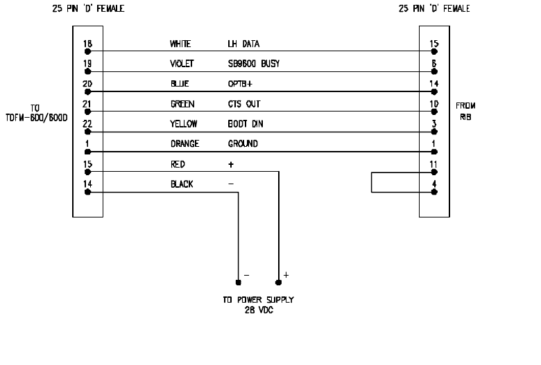
with the RSS and RIB. The radio cable supplied with the RIB will not connect to the TDFM-600/6000,
therefore you will need to fabricate or purchase the cable shown below.
FIGURE 2-2 Programming Cable
SECTION 3
INSTALLATION INSTRUCTIONS
3.1 GENERAL
This section contains information and instructions for the correct installation of the TDFM-600/6000
Transceiver.
3.2 EQUIPMENT PACKING LOG
3-2
Unpack the equipment and check for any damage that may have occurred during transit. Save the
original shipping container for returns due to damage or warranty claims. Check that each item on the packing
slip has been shipped in the container.
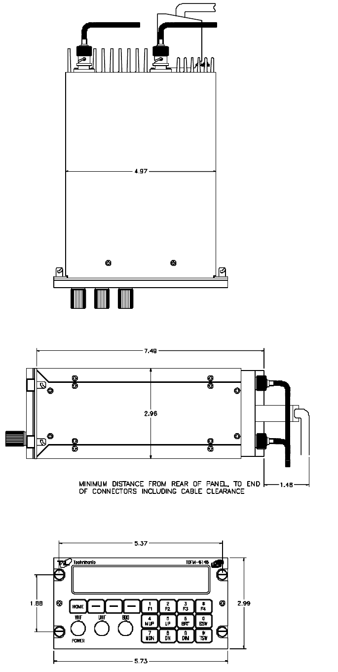
3.3 INSTALLATION
The TDFM-600/6000 Transceiver is designed to be dzus mounted and should be installed in conjunction
with an IN-600 installation kit. See figure 3-1 for an outline drawing of the unit with dimensions to
facilitate the installation.
3.4 INSTALLATION KIT - CONTENTS
The IN-600 installation kit (P/N 01xxxx-1) consists of:
1. One 25 pin Cannon D mating connector (female) complete with crimp pins and hood.
2. 3 BNC connectors.
3.5 ANTENNA INSTALLATION
The type and number of antennas depends on the model of transceiver being installed.
The following is a list of recommended antennas for the various RF modules:
VHF 136 to 176 MHz Comant part # CI-292
UHFLO 403 to 470 MHz Comant part # CI-275
UHFHI450 to 512 MHz Comant part # CI-275
800 806 to 870 MHz Comant part # CI-306
The antenna should be mounted on the bottom of the aircraft whenever possible.
Consult with instructions provided with the antenna. Connect the RF cables to the back
of the transceiver using the BNC connectors provided in the installation kit.
3-3

3-4
FIGURE 3-1 Outline Drawing for Model TDFM-600/6000
3.6 INSTALLATION - PIN LOCATIONS AND CONNECTIONS
>J1' 25 Pin D Connections - Use FEMALE Connector
Pin # Description
1Ground
2Main Power +28 VDC
3Mic 1
4Audio 1
5PTT 1
6Mic 2
7Audio 2
8PTT 2
9Mic 3
10 Audio 3
11 PTT 3
12 TX Data
13 RX Data
14 Ground
15 Main Power +28 VDC
16 Memory Up
17 Memory Down
18 LH Data
19 SB9600 Busy
20 OPTB+
21 CTS Out
22 Boot DIN
23 No Connection
24 No Connection

3-5
>J1' 25 Pin D Connections - Use FEMALE Connector
25 Panel Backlighting
TABLE 3-1
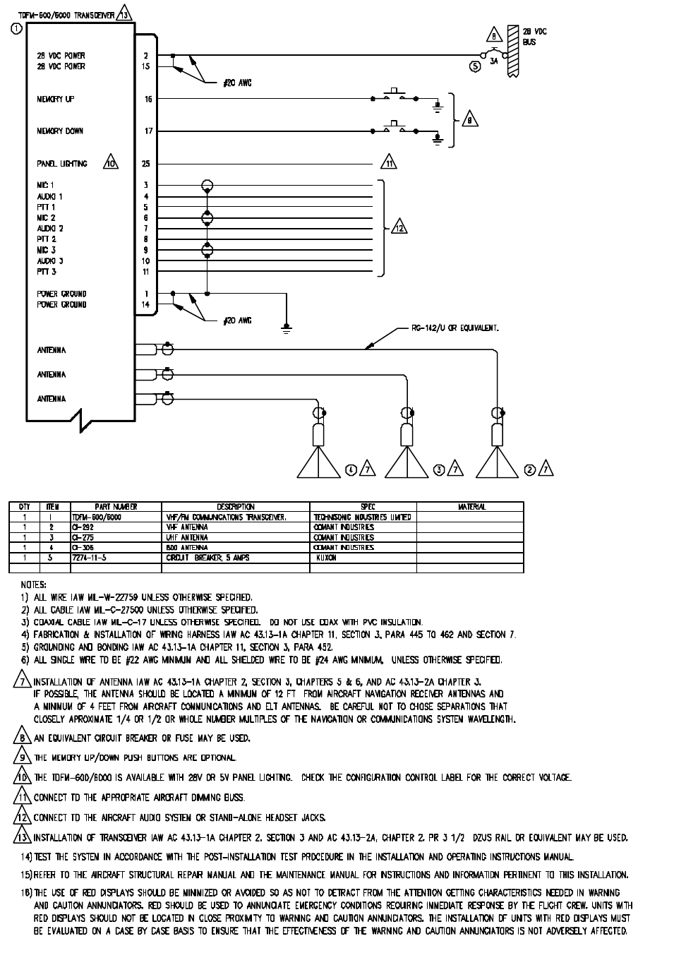
3.7 INSTALLATION - WIRING INSTRUCTIONS
Figure 3-2 shows all required connections and recommended wire sizes for the
TDFM-600/6000 transceiver.
3.8 MAIN GROUND - PINS 1 AND 14
Both pins should be connected to ground. The main ground is internally connected
to the chassis.
3.9 MAIN POWER +28 VDC - PINS 2 AND 15
Both pins should be connected to +28 volts DC +/- 15%.
3.10 MIC 1, 2 AND 3 - PINS 3, 6 AND 9
The microphone input signals shall be connected using shielded wire with the shield
connected to ground (pin 1 or 14). It is recommended for best results to leave the
other end of the shield floating to prevent ground currents.
3.11 AUDIO 1, 2 AND 3 - PINS 4, 7 AND 10
Audio outputs 1, 2 and 3 are 600 ohms impedance. The output power is 500 mW
maximum.
3.12 PTT 1, 2 AND 3 - PINS 5, 8 AND 11
The PTT lines should be floating when in receive and grounded for transmit. The
input has a pull up resistor to 5 volts. Connecting an audio panel which wishes to
see more may result in no receive audio from the audio panel. Connect a 1N4006
diode in series with the cathode towards the audio panel in this case.
3.13 TX DATA AND RX DATA - PINS 12 AND 13
These are an RS-232 serial port for future use. Leave both pins unconnected.
3.14 MEMORY UP AND MEMORY DOWN - PINS 16 AND 17
These pins can be used to scroll up and down through the zone/channel/mode/talk
group selections for the band currently displayed on the screen. The inputs normally
floating are grounded to activate. Two push buttons or a center off, SPDT, spring
loaded toggle switch are typically used on these inputs.
3-6
3.15 LH DATA, SB9600 BUSY, OPTB+, CTS OUT AND BOOT DIN - PINS 18
THROUGH 22
These pins are used for programming or updating the transceiver using Motorola
Radio Service Software (RSS) and are generally left unconnected. However, if it is
desirable to update the radio without removing it from the aircraft, these lines can be
run to a 25 pin D male connector located on the panel where a laptop computer can
plug in. Use the same pin numbers so the programming cable described in section
2 can be used (minus the power pins).
3.16 PANEL BACKLIGHTING - PINS 25
Connect to aircraft panel dimming bus. The transceiver comes with either 28 VDC
or 5 VAC backlighting circuits.
3-7
FIGURE 3-2 Wiring connections and notes for the TDFM-600/6000 Transceiver