Technisonic T3400 VHF AM RF MODULE User Manual
Technisonic Industries Limited VHF AM RF MODULE
User Manual

T3400 RF Module
VHF AM
Users Guide
DOCUMENT NO: 136584
REVISION:
DATE OF ISSUE: NOVEMBER 06, 2013
Technisonic Industries
Limited
240 Traders Boulevard, Mississauga, Ontario L4Z 1W7
Tel: (905) 890-2113 Fax: (905) 890-5338
www.til.ca
This document contains designs and other information which are the property of Technisonic Industries Ltd. This
document may not in whole or in part, be duplicated or disclosed or used for manufacture of the part disclosed herein,
without the prior written permission of Technisonic Industries Ltd.

INTRODUCTION
The T3400 RF module is a VHF AM transceiver assembly that operates in 117.975 - 137 MHz range.
The transceiver module is designed to be installed and operated in the Technisonic Multiband Airborne
Radio TDFM-9300/9200 platform. All external power and antenna connections are provided by the TDFM
9300 as well as controls are via the front panel and display from the TDFM 9300.
The RF module is capable of operating Amplitude Modulation with maximum transmit power of 5 watts.
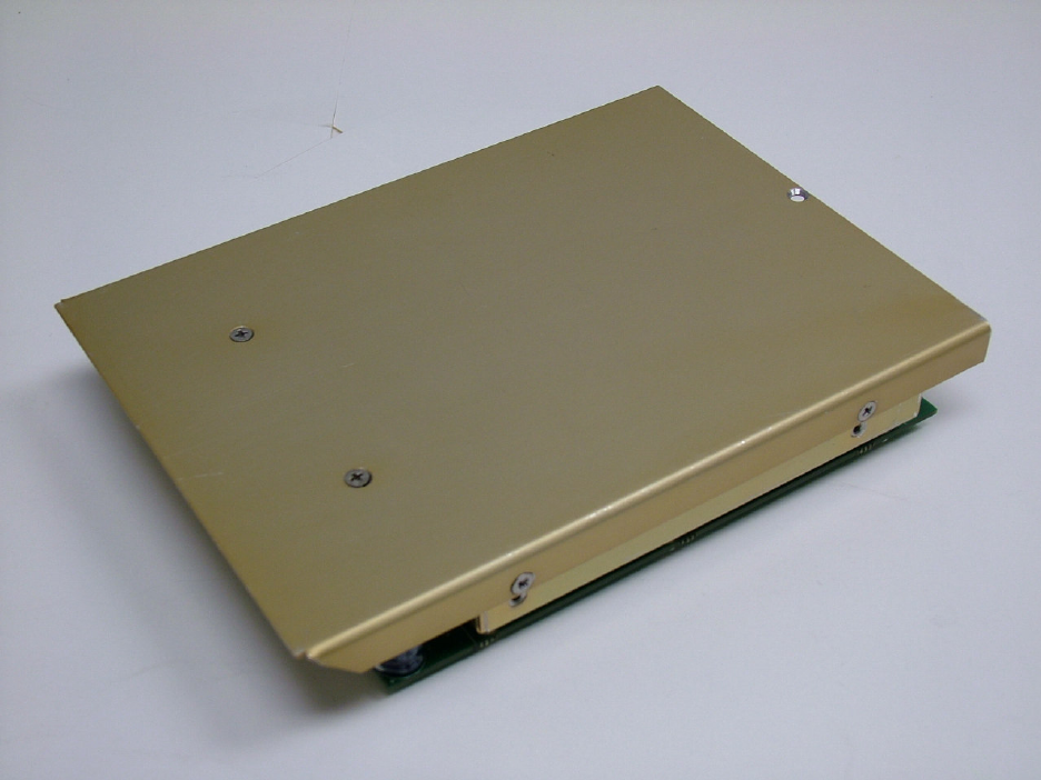
FIGURE 1: Overall view of the T3400 RF Module

NOTES
ESD CAUTION
This unit contains static sensitive devices. Wear a grounded wrist strap and/or conductive gloves
when handling printed circuit boards.
FCC COMPLIANCE INFORMATION
This device complies with Part 15 of the FCC Rules. Operation is subject to the following two conditions:
(1) this device may not cause harmful interference and (2) this device must accept any interference
received, including interference that may cause undesired operation.
WARNING: For compliance with FCC RF Exposure Requirements the mobile transmitter
antenna installation shall comply with the following two conditions:
1. The transmitter antenna gain shall not exceed 3 dBi.
2. The transmitter antenna is required to be located outside of a vehicle and kept at a separation distance of 70 cm
or more between the transmitter antenna of this device and persons during operation.
NOTE: This equipment has been tested and found to comply with the limits for a Class B digital device,
pursuant to part 15 of the FCC Rules. These limits are designed to provide reasonable protection against
harmful interference in a residential installation. This equipment generates, uses and can radiate radio
frequency energy and, if not installed and used in accordance with the instructions, may cause harmful
interference to radio communications. However, there is no guarantee that interference will not occur in a
particular installation. If this equipment does cause harmful interference to radio or television reception,
which can be determined by turning the equipment off and on, the user is encouraged to try to correct the
interference by one or more of the following measures:
—Reorient or relocate the receiving antenna.
—Increase the separation between the equipment and receiver.
—Connect the equipment into an outlet on a circuit different from that to which the receiver is connected.
—Consult the dealer or an experienced radio/TV technician for help.

TECHNICAL CHARACTERISTICS
Specification Characteristic
Model Designation: T3400
Physical Dimensions: Approx. (L) 6.75" x (W) 5.0" x (H) 1.25"
Operating Temperature Range: -30° C to +60° C
Power Requirement:
Voltage:
Current:
28 VDC ± 5%
300 mA minimum / 1.2A maximum
Audio Output Power: 500 mW into 600
Ω
FCC ID: IMA-T3400
INDUSTRY CANADA: 120A-T3400
RF Output Power: 5 Watts, 2.5 (Carrier)
Frequency Range
117.975 – 137 MHz TX
117.975 – 137 MHz RX
No. of channels: 200 Channels
Minimum Channel Stepping 25 KHz
Transmitter section
Audio Distortion:
Frequency Stability in ppm:
Maximum Modulation (max):
Maximum Modulation (min):
Spurious Attenuation:
Harmonic Attenuation:
Audio Input
<5%
±2.5
95%
75%
-60 dB below carrier level
-60 dB below carrier level
50 mV at 2.5 kHz into
200 ohm input circuit for
30% modulation (adjustable)
Receiver section
Sensitivity in uV (12dB SINAD): Better than 2.0
Adjacent Channel Selectivity
Spurious Attenuation:
Third Order Intermodulation
Image Attenuation
Hum and Noise
Audio Distortion
Antenna Conducted Emission
-70 dB (25 kHz)
-70
-70
-60
>40
<5%
-70dBm

FCC ID LABELS
Before the T3400 is installed in the TDFM-9300, the FCC/INDUSTRY CANADA label must be applied.
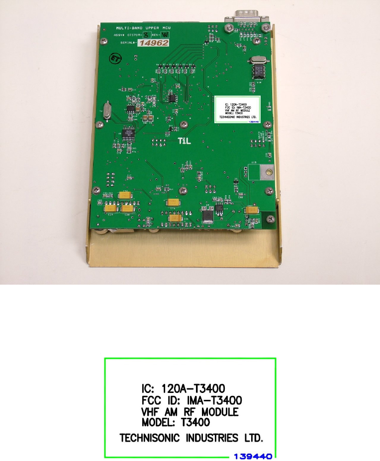
FIGURE 2: T3400 RF Module with FCC/IC Label applied to the bottom
The FCC/Industry Canada label is shown below. Place the label on the bottom of the controller board as
shown in Figure 2.
FIGURE 3: T3400 FCC/Industry Canada Label
INSTALATION
The T3400 module should be installed in the TDFM 9300 in accordance with TIL document 136569
“TDFM-9300 FINAL ASSEMBLY SSP".
The T3400 is intended to be mounted in the TDFM 9300/9200 chassis and is not visible. Therefore, a
second label must be applied to the outside of the TDFM 9300 that contains the following text:
“TDFM 9300 Multiband Transceiver. Contains Module: FCC ID IMA-T3400”.
In addition, external labeling for Industry Canada shall be applied to the TDFM 9300 to include the
following text: “Contains IC: 120A-T3400”.

WARNING AND DISCLAIMER
Changes or modifications not expressly approved by Technisonic Industries could void the user’s
authority to operate the equipment.
This manual is designed to provide information about the T3400 RF Module. Every effort has been made
to make this manual as complete and accurate as possible.
WARRANTY INFORMATION
The Model T3400 Transceiver is under warranty for one year from date of purchase. Failed units caused
by defective parts, or workmanship should be returned to:
Technisonic Industries Limited
240 Traders Boulevard
Mississauga, Ontario L4Z 1W7
Tel: (905) 890-2113
Fax: (905) 890-5338