Technisonic TDFM-136A VHF/FM Digital Airborne Transceiver User Manual 2

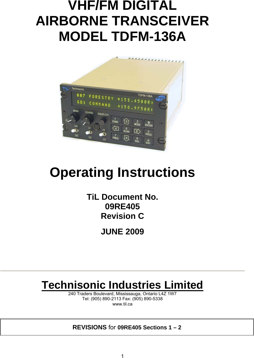
Technisonic Industries Limited VHF/FM Digital Airborne Transceiver 2

Contents

User Manual 2

 1   VHF/FM DIGITAL AIRBORNE TRANSCEIVER MODEL TDFM-136A      Operating Instructions   TiL Document No. 09RE405 Revision C  JUNE 2009        Technisonic Industries Limited 240 Traders Boulevard, Mississauga, Ontario L4Z 1W7 Tel: (905) 890-2113 Fax: (905) 890-5338 www.til.ca   REVISIONS for 09RE405 Sections 1 – 2
 2REV  SECTION - PAGE  -  DESCRIPTION DATE EDITED A  - Table 1-1  Changed upper operating temp to +60 C.  Apr.13/09  S.M. B  - Table 1-5 - STC Appr. - Table 1-5 Changed lower operating temp to –30 C. Change references of DO-160C to 160D. Change Temp & Alt to B4 and D1. Change Magnetic Effect  to class Z. May 26/09  H.D. C  - Table 1-4  - Footer, all pages. Change RF Output Power Low to read “1W”. Remove “Installation and” from “Installation and Operating Instructions”. June 15/09  H.D.
TECHNISONIC INDUSTRIES LIMITED www.til.ca   TDFM-136A    Operating Instructions        Page A TiL 09RE405   CAUTION ! STATIC SENSITIVE !  This unit contains static sensitive devices. Wear a grounded wrist strap and/or conductive gloves when handling printed circuit boards.    FCC COMPLIANCE INFORMATION This device complies with Part 15 of the FCC Rules. Operation is subject to the following two conditions: (1) this device may not cause harmful interference and (2) this device must accept any interference received, including interference that may cause undesired operation.  NOTE:  This equipment has been tested and found to comply with the limits for a Class B digital device, pursuant to Part 15 of the FCC Rules. These limits are designed to provide reasonable protection against harmful interference in a residential installation. This equipment generates, uses, and can radiate radio frequency energy and, if not installed and used in accordance with the instruction manual, may cause harmful interference to radio communications. However, there is no guarantee that interference will not occur in a particular installation. If this equipment does cause harmful interference to radio or television reception, which can be determined by turning the equipment off and on, the user is encouraged to try to correct the interference by one or more of the following measures: •  Re-orient or relocate the receiving antenna •  Increase the separation between the equipment and receiver •  Connect the equipment into an outlet or circuit different from that to which the receiver is connected. •  Consult the dealer or an experienced radio/TV technician for help.     WARNING Changes or modifications not expressly approved by Technisonic Industries could void the user’s authority to operate the equipment.     WARRANTY INFORMATION The Model TDFM-136A transceiver is under warranty for one year from date of purchase. Failed units caused by defective parts, or workmanship should be returned to:   Technisonic Industries Limited 240 Traders Boulevard Mississauga, Ontario L4Z 1W7  Tel: (905) 890-2113 Fax: (905) 890-5338   NOTICE: The above stated address supersedes all others that may appear otherwise in this manual.
TECHNISONIC INDUSTRIES LIMITED www.til.ca   TDFM-136A    Operating Instructions        Page B TiL 09RE405   STC APPROVAL NOTE  Presently, no TSO standard exists for airborne FM transceivers. To make it easier for installation agencies to provide their customers with an approved installation supported by an effective Airworthiness Approval, Technisonic has secured Supplemental Type Certificate (STC) Approvals (both US and Canadian) on its Airborne FM products for many helicopters currently being delivered in the US and Canada as well as a number of single engine fixed wing aircraft. The above referenced DO-160D test data is also on file and available from Technisonic to support approval requirements in airframes for which Technisonic does not possess an STC.  Approved aircraft types are listed in the attachments to the formal STC documents. These STC's are the exclusive property of Technisonic and require the written authority of Technisonic for their use. To assist Factory Authorized Technisonic Dealers in the certification process, we have placed copies of our Canadian and US STC's on our web site along with a letter of authorization for their use. These documents may be downloaded and used as support for the technical submission to FAA or Transport Canada. Only authorized factory dealers/installers are permitted to download and make use of these documents on behalf of their customers (end users) in support of regulatory agency approval. Please refer to the Technisonic web site www.til.ca for the latest issue of available STC’s and letter of authorization for use.         COPYRIGHT NOTICE This document contains designs and other information which are the property of Technisonic Industries Ltd.  Except for rights expressly granted by contract to the Canadian Government, or to the United States Government, this document may not, in whole or in part, be duplicated or disclosed or used for manufacture of the part disclosed herein, without the prior permission of Technisonic Industries Ltd.         WARNING AND DISCLAIMER This manual is designed to provide information about the TDFM-136A. Every effort has been made to make this manual as complete and accurate as possible.
TECHNISONIC INDUSTRIES LIMITED www.til.ca   TDFM-136A    Operating Instructions        Page i TiL 09RE405   TABLE OF CONTENTS  SECTION  TITLE   PAGE Table of Contents ..................................................................................................................................      i List of Figures ........................................................................................................................................     iv List of Tables .........................................................................................................................................      v    SECTION 1  GENERAL DESCRIPTION 1.1 Introduction ............................................................................................................................    1-1 1.2 Description .............................................................................................................................    1-1 1.3  Purpose of Equipment ...........................................................................................................    1-1 1.4 Model Variation  ......................................................................................................................    1-2 1.5 Technical Characteristics  .....................................................................................................    1-3 1.6 Certification Summary ...........................................................................................................    1-5    SECTION 2  OPERATING INSTRUCTIONS 2.1 Command Methodology  ........................................................................................................    2-1 2.2.1 Programming Guide ...............................................................................................................    2-3 2.2  Operator Level 1 Commands  ................................................................................................    2-5 L1-1 Increase Display Brightness ..............................................................................................    2-5 L1-2 Increase Display Brightness ..............................................................................................    2-5 L1-3  Edit or Select Channel Operating Mode  ...........................................................................    2-5 L1-4  Scroll Backwards through Available Memories .................................................................    2-6 L1-5 Start/Stop Scan .................................................................................................................    2-6 L1-6  Scroll Forward through Available Memories  .....................................................................    2-6 L1-7  Edit Channel Operating Frequency ...................................................................................    2-7 L1-8 Decrease Display Brightness  ............................................................................................    2-7 L1-9 Edit Channel Squelch Mode ..............................................................................................    2-8 L1-9.1  Edit Noise Squelch Value .........................................................................................    2-8 L1-9.2 Select CTCSS Tone .................................................................................................    2-9 L1-9.3 Select DCS Code  .....................................................................................................    2-9 L1-9.4  Edit Project 25 Talkgroup Value ..............................................................................  2-10 L1-9.5  Edit Project 25 NAC Value  .......................................................................................  2-10 L1-9.6  Edit Project 25 ID Call Value ....................................................................................  2-11 L1-0 Command Level Up  ..........................................................................................................  2-11 L1-# Not Used ...........................................................................................................................  2-11 L1-* Not Used ...........................................................................................................................  2-11  2.3 Operator Level 2 Commands .......................................................................................................  2-12 L2.1  Create/Edit All Channel Information ..................................................................................  2-12 L2-1.1  Entering a Memory Number .....................................................................................  2-12 L2-1.2  Enter a Scan Zone & Enabling/Disabling Scan ........................................................  2-12 L2-1.3  Enter a Text Description ...........................................................................................  2-13 L2-1.4  Enter an Operating Mode .........................................................................................  2-13 L2-1.5 Enter a Frequency ....................................................................................................  2-13 L2-1.6  Enter the Squelch Parameters .................................................................................  2-13
TECHNISONIC INDUSTRIES LIMITED www.til.ca   TDFM-136A    Operating Instructions        Page ii TiL 09RE405   SECTION  TITLE   PAGE L2-2 Copy Guard to Main  ..........................................................................................................  2-13 L2-3 Lock Keypad ......................................................................................................................  2-13 L2-4 Not Used ...........................................................................................................................  2-13 L2-5  Edit Scan List & Enable/Disable Scan  ..............................................................................  2-14 L2-6  Edit Channel Text Description ...........................................................................................  2-14 L2-7 Create Shadow Channel  ...................................................................................................  2-15 L2-7.1  Selecting a Primary Number to Base the Shadow On .............................................  2-15 L2-7.2  Selecting a Primary Number to Base the Shadow On .............................................  2-16 L2-8 Copy Main to Guard  ..........................................................................................................  2-16 L2-9 Edit Unit ID Value ..............................................................................................................  2-17 L2-0 Command Level Up  ..........................................................................................................  2-17 L2-* Command Level Down ......................................................................................................  2-17 L2-# Not Used ...........................................................................................................................  2-17  2.4 Operator Level 3 Commands .......................................................................................................  2-18 L3-1 Select Boot Channel  .........................................................................................................  2-18 L3-2 Unused ..............................................................................................................................  2-18 L3-3 Select Hex/Decimal Edit Mode ..........................................................................................  2-18 L3-4  Display Software Release and Version Information ..........................................................  2-19 L3-5 Edit Scan Parameters .......................................................................................................  2-19 L3-5.1  Setting the Revert Mode default: last contacted ......................................................  2-19 L3-5.2  Setting the Reply-Timer Range: 0-20s, Default: 3 seconds .....................................  2-20 L3-5.3  Setting the Monitor-Timer Range: 1-90s, Default: 10 seconds ................................  2-20 L3-5.4  Setting the Delay-Timer Range: 0-15s, Default: 5 seconds .....................................  2-21 L3-6 Configure the PTT Timer ...................................................................................................  2-22 L3-7  Side tone Audio Level Adjust  ............................................................................................  2-22 L3-8  PC Data Upload/Download  ...............................................................................................  2-22 L3-9  Display Channel Squelch Parameters  ..............................................................................  2-23 L3-0 Command Level Up  ..........................................................................................................  2-23 L3-* Command Level Down ......................................................................................................  2-23 L3-# Unused ..............................................................................................................................  2-23  2.5 Maintenance Commands ..............................................................................................................  2-24 Accessing the Maintenance Commands ..................................................................................  2-24 L4-1 Set Default Record ............................................................................................................  2-25 L4-2 Unused ..............................................................................................................................  2-26 L4-3  Set Command Permissions ...............................................................................................  2-26 L4-4 Unused ..............................................................................................................................  2-27 L4-5 Unused ..............................................................................................................................  2-27 L4-6 Unused ..............................................................................................................................  2-27 L4-7 Unused ..............................................................................................................................  2-27 L4-8 Unused ..............................................................................................................................  2-27 L4-9 Set Squelch Restrictions ....................................................................................................  2-28 L4-9.1 Restricting the Squelch Modes Available to Select  .................................................  2-28 L4-9.2  Restricting the Squelch Modes Value Edit ...............................................................  2-29 L4-9.3  Restricting the CTCSS Tone and DCS Code Values  ..............................................  2-29 L4-0 Unused ..............................................................................................................................  2-29 L4-# Unused ..............................................................................................................................  2-29 L4-* Command Level Down ......................................................................................................  2-29
TECHNISONIC INDUSTRIES LIMITED www.til.ca   TDFM-136A    Operating Instructions        Page iii TiL 09RE405   SECTION  TITLE   PAGE 2.6 Understanding Radio Operation ..................................................................................................  2-30 Basic Radio Operation ...................................................................................................................  2-30 Channels and Memories ................................................................................................................  2-31 Memory Parameters  ......................................................................................................................  2-31 Operating Modes ...........................................................................................................................  2-31 Squelch Modes ..............................................................................................................................  2-32 IDCall Operation ............................................................................................................................  2-33 Scan Operation ..............................................................................................................................  2-33 Mixed Mode Operation ...................................................................................................................  2-34     APPENDICES APPENDIX A CTCSS TONES and DCS CODES.................................................................................    A-1
TECHNISONIC INDUSTRIES LIMITED www.til.ca   TDFM-136A    Operating Instructions        Page iv TiL 09RE405   LIST OF FIGURES  FIGURE  TITLE   PAGE2-1  User Screen showing the Command Level Display Position ......................................................2-1 2-2  User Screen to Enter a Memory Number ....................................................................................2-5 2-3  User Screen to Edit the Operating Mode ....................................................................................2-5 2-4 User Screen during Scan ............................................................................................................2-6 2-5  Selecting a Memory/Channel that Doesn't Support Scan ...........................................................2-6 2-6  User Screen to Edit the frequency ..............................................................................................2-7 2-7  User Screen to Edit the Squelch Mode .......................................................................................2-8 2-8  User Screen to Edit the Squelch Value .......................................................................................2-8 2-9  User Screen to Edit the CTCSS Tone Value  ..............................................................................2-9 2-10  User Screen to Edit the DCS Code Value  ..................................................................................2-9 2-11  User Screen to Edit the P25 TalkGroup Value  .........................................................................2-10 2-12  User Screen to Edit the P25 NAC Valu .....................................................................................2-10 2-13  User Screen to Edit the P25 ID Call Value  ...............................................................................2-11 2-14  User Screen to Enter a Scan List or Enable/Disable Scan .......................................................2-14 2-15  User Screen Showing Scan Disabled for this Memory .............................................................2-14 2-16  User Screen to Edit the Text Description ..................................................................................2-14 2-17  User Screen to Enter a Primary Memory for the Shadow Channel ..........................................2-15 2-18  User Screen to Enter a Shadow Channel Memory Number .....................................................2-16 2-19  User Screen to Edit the Shadow Channel Parameters (text) ...................................................2-16 2-20  User Screen to Select Main Channel Boot Mode  .....................................................................2-18 2-21  User Screen to Select the Numeric Edit Mode  .........................................................................2-18 2-22  User Screen Showing the Code Release Information ..............................................................2-19 2-23  User Screen to Select the Scan Revert Mode  ..........................................................................2-19 2-24  User Screen to Set the Scan Reply Timer Value ......................................................................2-20 2-25  User Screen to Set the Scan Monitor Timer Value ...................................................................2-20 2-26  User Screen to Set the Scan Delay Timer Value ......................................................................2-21 2-27  User Screen to Set the PTT Timer Value .................................................................................2-21 2-28  User Screen to Set the Sidetone Audio Level  ..........................................................................2-22 2-29  User Screen to Upload/Download Memory Data to the PC ......................................................2-22 2-30  User Screen to Display the Receive Squelch Parameter Values .............................................2-23 2-31  User Screen to Display the Transmit Squelch Parameter Values ............................................2-23 2-32  The Screw positions to remove the Left-hand Side Panel ........................................................2-24 2-33  The Shunt Position to Enable Level 4 Access  ..........................................................................2-24 2-34  The Screen to Edit the Level 1 Permissions .............................................................................2-26 2-35  The Screen to Edit the Level 2 Permissions .............................................................................2-26 2-36  User Screen to Edit the Level 3 Permissions ...........................................................................2-26 2-37  The Screen to Set Available Squelch Modes for Analog Receive ............................................2-28 2-38  The Screen to Restrict Editing of the Squelch Mode Value ......................................................2-29 2-39  The Screen to Restrict Available CTCSS Tones  ......................................................................2-29 2-40  The Screen to Restrict Available DCS Codes  ..........................................................................2-29 2-41  The TDFM-136A Front Panel Layout ........................................................................................2-30 2-42  Identifying Graphic for Primary Channel with Shadows ............................................................2-35 2-43  Identifying Graphic for Shadow Channel ..................................................................................2-35
TECHNISONIC INDUSTRIES LIMITED www.til.ca   TDFM-136A    Operating Instructions        Page v TiL 09RE405   LIST OF TABLES  TABLE  TITLE   PAGE 1-1  TDFM-136A – General Characteristics .......................................................................................1-3 1-2  TDFM-136A – Operational Characteristics .................................................................................1-4 1-3  TDFM-136A – Receiver Characteristics – Main and Guard .......................................................1-4 1-4  TDFM-136A – Transmitter Characteristics  .................................................................................1-5 1-5  TDFM-136A – Environmental Testing Summary  ........................................................................1-5  2 Command Levels ........................................................................................................................2-1 2-1 Command Level Reference  ........................................................................................................2-3 2-2 Abbreviations and Symbols Used ...............................................................................................2-4 2-3 Channel Operating Modes  ..........................................................................................................2-5 2-4  Receive and Transmit Squelch Modes  .......................................................................................2-8 2-5 Extra Characters for Text Edit ...................................................................................................2-15 2-6 Channel Template Factory Defaults .........................................................................................2-25 2-7  Permission Applicability with respect to Command Levels .......................................................2-27 2-8  Squelch Modes that can be Restricted .....................................................................................2-28 2-9  Receive and Transmit Squelch Modes  .....................................................................................2-32
TECHNISONIC INDUSTRIES LIMITED www.til.ca   TDFM-136A    Operating Instructions        Page vi TiL 09RE405   This page left intentionally blank.
TECHNISONIC INDUSTRIES LIMITED www.til.ca   TDFM-136A    Installation and Operating Instructions                 Page 1-1 TiL 09RE405   SECTION 1 - GENERAL DESCRIPTION  1.1 INTRODUCTION This publication provides operating and installation information for the TDFM-136A, Digital Transceiver manufactured by Technisonic Industries Limited. The TDFM-136A is Project 25 (P25), Phase 1 compliant. The unit offers digital or conventional analog FM communications over an extended frequency range with selectable channel spacing and is intended for use (in the U.S.) only by government agencies or contractors thereto, who have obtained licensing for operation in the 136-150 MHz portion of the band. If the TDFM-136A transceiver is used in CANADA, operation is restricted to the following sub bands: 138-144, 148-148.99, 149.005-150.005 and 150.05-174 MHz. Furthermore the frequency agile transceiver is restricted to airborne use and must not be operated as a base station in Canada.  1.2   DESCRIPTION The TDFM-136A, Transceiver is a frequency agile, fully synthesized airborne transceiver capable of operating in the 136.000 MHz to 174.000 MHz frequency range in 2.5 kHz increments with either 25 kHz analog, 12.5 kHz analog channel spacing and P25, 12.5 kHz digital modulation on a channel by channel basis. The Transceiver can operate without restriction on any split frequency pair in the band and also incorporates a two channel synthesized guard receiver.  The TDFM-136A Transceiver provides 230 operator accessible memory positions. Each of which is capable of storing Scan List membership information, up to eight (8) character alphanumeric identifier, and Operating Mode information. In addition each memory position contains information for both transmit and receive including: frequency, CTCSS tone, DCS (DPL) code, P25 TalkGroup, and P25 Network Access Code (NAC) information.  Channel operating parameters, including frequency and other related data, are presented on a 48-character, two-line LED matrix display. Data entry and function control takes place via a 12-button keypad.  1.3   PURPOSE OF EQUIPMENT The TDFM-136A, Digital VHF/FM Transceiver is designed to provide secondary airborne communications to facilitate operations which are typically performed in a low altitude environment. The transmitter section of this unit has a minimum of 8 watts and does not exceed 10 watts output power, which may be reduced by a front panel switch to 1 watt, in order to reduce interference to land based systems.
TECHNISONIC INDUSTRIES LIMITED www.til.ca   TDFM-136A    Operating Instructions                     Page 1-2 TiL 09RE405   1.4   MODEL VARIATION There are twelve variations of the Model TDFM-136A Transceiver.  All units offer identical features and performance except for the following differences:  TDFM-136A, P/N 091258-1-10      GREEN display 28v back lighting, no Encryption. TDFM-136A, P/N 091258-1-11      GREEN display 28v back lighting, with Encryption. TDFM-136A, P/N 091258-2-10      RED display 28v back lighting, no Encryption. TDFM-136A, P/N 091258-2-11       RED display 28v back lighting, with Encryption. TDFM-136A, P/N 091258-3-10      NV display 28v back lighting, no Encryption. TDFM-136A, P/N 091258-3-11       NV display 28v back lighting, with Encryption. TDFM-136A, P/N 091258-4-10      GREEN display 5v back lighting, no Encryption. TDFM-136A, P/N 091258-4-11      GREEN display 5v back lighting, with Encryption. TDFM-136A, P/N 091258-5-10      RED display 5v back lighting, no Encryption. TDFM-136A, P/N 091258-5-11       RED display 5v back lighting, with Encryption. TDFM-136A, P/N 091258-6-10      NV display 5v back lighting, no Encryption. TDFM-136A, P/N 091258-6-11       NV display 5v back lighting, with Encryption.                           1.5 TECHNICAL CHARACTERISTICS The tables below provide the technical characteristics for the Technisonic Industries Ltd. Model TDFM-136A.
TECHNISONIC INDUSTRIES LIMITED www.til.ca   TDFM-136A    Operating Instructions                     Page 1-3 TiL 09RE405  TABLE 1-1 TDFM-136A – General Characteristics Characteristic Specification Dimensions (including heat sink)  Approx. 8.0" X 3.0" X 5.75" Weight  Approx. 3.5 Lbs (1.6 Kg) Mounting    Panel Mount via DZUS fasteners   Power Requirement:    Voltage    Current  28.0 VDC, ±15% Receive - 0.7 A Max. Transmit Low Power (1W) - 1.3 A Max. Transmit High Power (8-10W) - 2.0 A Max.   Audio Output Power:    Headset    Speaker Output  0.5 Watts into 600 ohms 2.5 Watts min. into 4 ohms   Back Lighting  28 Volts (standard) 5 Volts (specify)   Display Colour  Green (standard) Red (specify) NVG (optional)   Temperature Range:    Operating    Storage  -30ºC to +60ºC -55ºC to +85ºC Altitude 50,000 feet
TECHNISONIC INDUSTRIES LIMITED www.til.ca   TDFM-136A    Operating Instructions                     Page 1-4 TiL 09RE405   TABLE 1-2 TDFM-136A – Operational Characteristics Characteristic Specification Frequency Range:  136.000 to 174.000 MHz Operating Modes:  Conventional analog: 12.5 / 25 kHz. P25 CAI: 12 KBPS FSK, 9.6 KBPS C4FM Channel Spacing:  25 kHz. or 12.5  kHz Programmable Memories:    Scan Lists    Description    Operating Modes    Frequency    Squelch Modes 230 memories  15 scan lists  Up to 8 characters, alpha-numeric   Analog Wide, Analog Narrow, P25 Digital  Rx/Tx (Simplex/Duplex), 136.0000 – 174.0000  Rx/Tx (Simplex/Duplex), CTCSS Tones, DCS Codes,    P25 TalkGroup, P25 NAC Guard Receiver:    Description    Operating Modes    Frequency    Squelch Modes 2 channels programmed with:   Up to 8 characters, alpha-numeric    Analog Wide, Analog Narrow, Digital   Rx/Tx (Simplex/Duplex), 136.0000 – 174.0000 MHz.   Rx/Tx (Simplex/Duplex), CTCSS Tones, DCS Codes,      P25 TalkGroup, P25 NAC CTCSS Tones  42 CTCSS tones, including all standard tones. DCS Codes  All standard DCS (DPL1) codes P25 TalkGroup  $0000 to $FFFF  ( 0 to 65535 )  P25 Network Access Code (NAC)  $000 to $FFF  ( 0 to 4095 )  DPL1 is a trademark of Motorola Corporation  TABLE 1-3 TDFM-136A – Receiver Characteristics – Main and Guard Characteristic Specification Sensitivity at 12 dB SINAD  -116dBm Adjacent Channel Selectivity  -60dB (25 or 12.5 kHz) Spurious Attenuation  -70 dB Third Order Intermodulation  -70 dB Image Attenuation  -80 dB FM Acceptance   ± 6 kHz Hum and Noise  better than 45dB Audio Distortion  less than 5% Antenna Conducted Emission  less than -57dBm
TECHNISONIC INDUSTRIES LIMITED www.til.ca   TDFM-136A    Operating Instructions                     Page 1-5 TiL 09RE405   TABLE 1-4 TDFM-136A – Transmitter Characteristics Characteristic Specification RF Output Power:      Low      High  1W. 10W. Output Impedance  50 ohms Maximum Deviation:      Wide (25 kHz)      Narrow (12.5 kHz)  ± 5 kHz  ± 2.5 kHz Maximum Deviation – Narrow  ± 2.5 kHz  (12.5 kHz mode) Spurious Attenuation  -90 dB below carrier level Frequency Stability  ± 2.5 ppm Microphone Circuit  Carbon or equivalent Sidetone Output  0.5W (max) into 600 ohms Harmonic Attenuation  -65 dB below carrier level FM Hum And Noise  -40 dB Audio Input  50 mV at 2.5 into 200 Ω input circuit for ± 3.5 deviation, adjust. Audio Distortion  Less than 5% 1.6 CERTIFICATION SUMMARY The following table gives a summary of DO-160D Environmental Testing for Technisonic Model TDFM-136A, VHF Digital Transceiver.   TABLE 1-5 TDFM-136A – Environmental Testing Summary Conditions  Section  Description of Conducted Tests Temperature and Altitude  4.0  Equipment tested to categories B4 and D1. Temperature Variation  5.0  Category B. Humidity 6.0 Category A. Operational Shock and Crash Safety 7.0 Category A. Vibration  8.0  Equipment is tested without shock mounts to categories S and U. Magnetic Effect  15.0  Equipment is class Z. Power Input  16.0  Category B. Voltage Spike  17.0  Category B. Audio Frequency Susceptibility  18.0  Category B. Induced Signal Susceptibility  19.0  Category A. Radio Frequency Susceptibility  20.0  Category U. RF Emission (DO-160D) RF Emission (DO-160C) 21.0 Category B. Category Z. Electrostatic Discharge  25.0  Category A.
TECHNISONIC INDUSTRIES LIMITED www.til.ca   TDFM-136A    Operating Instructions                     Page 2-1 TiL 09RE405   SECTION 2 – OPERATING INSTRUCTIONS  This section provides the user with a reference of the keypad accessible programming features of the Technisonic TDFM-136A VHF/FM Digital Transceiver. This section is divided into subsections as follows: 2.1      command structure overview and terms 2.2, 2.3, 2.4 and 2.5   detailed command descriptions by level 2.6       detailed operating description 2.1   COMMAND METHODOLOGY This section describes how the TDFM-136A command structure is organized. Command Levels In order to accommodate the necessary commands, the commands have been divided into different levels, each command level has up to 12 commands numbered 0-9, # and *; the zero (0), and the ESC (*) key are functions for every level, they allow the user to move between levels as follows:  step up through command levels  step down through command levels When stepping through command levels, the indicated level is shown in subscript in the 4th character position on the lower line of the display. Note that this display position is left blank for the default level (level1). Table 2-1 shows the command levels and the associated display character.  Table 2 Command Levels COMMAND LEVEL DISPLAY Command/Operator L1  blank Command/Operator L2  2 Command/Operator L3  3 Command/Maintenance L4  4  Figure 2-1 below shows the front panel display for different Command levels. 0 0 1    M a  i  n            D 1 3 4  .  0 0 0 0 R g G D 2 3  G u a r  d 2        w 1 7 4    0 0 0 0 R t FIGURE 2-1 User Screen showing the Command Level Display Position  In addition to the 3-operator available command levels, the unit can be put into a mode that allows access for Maintenance. This 4th command level (L4) allows authorized personnel to set operating policy for the radio through the use of 'Permissions'. These are explained in section 2-8. This command level should NEVER be enabled in flight.  In order to restrict access to the Command/Maintenance Level 4, the side cover must be removed, and a maintenance jumper must be installed on the MCU board (see Figure 2-33).
TECHNISONIC INDUSTRIES LIMITED www.til.ca   TDFM-136A    Operating Instructions                     Page 2-2 TiL 09RE405   Command Types There are two basic command types: Inherent and Edit. An Inherent command is one that requires no additional input from the user, such as the ‘memory brightness’ or ‘scroll memory’ commands. An Edit command requires further input from the user.  Command Scope The Main or the Guard Channel can be affected by most, but not all, edit commands. The channel to be edited depends on the position of the MN/GD and the G1/G2 front panel switches. In this manual, the scope of the command is given on the command title line as follows:  (MN/GD)  for a command that is valid in both Main and Guard, (MN)    for a command that is valid for Main only Blank    for a command that is not subject to channel restrictions.  Command Conventions After selecting the command, the system expects further input from the user. All edit commands may be terminated in the same way:  accept the entry and return abandon the entry and exit  The commands that allow the user to choose an option from a list will always use the up/down arrows (key 2 and key 8 to step UP and DOWN respectively through the available choices). In addition, the key that was used to enter the function can be used to step UP through the available choices.  Example:  The L1-3 Mode command allows the user to select the radio's operating mode (analog wide, analog narrow, or P25 digital). Once  the  user  has  selected the command,    they can press  to step up, or  to step down through the choices. The advantage of the 'entry key' step method is that the user does not have to move their finger to a different key to make the choice once the command has been selected.
TECHNISONIC INDUSTRIES LIMITED www.til.ca   TDFM-136A    Operating Instructions                     Page 2-3 TiL 09RE405   2.2.1 Programming Guide •  The channel to be edited depends on the position of the MN/GD and the G1/G2 front panel switches. Table 2-1 below shows the commands divided into command levels: one, two, three, and four. •  Radio’s default Command/Operator Level 1 is the only command level not displayed in the 4th character position on the lower row of the display. •  To step through the Command Level, press the   key (refer to Table 2-1). The radio defaults back to the command level 1 in approximately 5 seconds.       TABLE 2-1 Command Level Reference Key  Command/ Operator Level 1 Command/ Operator Level 2  Command/ Operator Level 3 1 Command/ Maintenance Level 4 1 CHAN  Select Main Memory  Program New Memory  Select Boot Memory  Set Default Record 2 up  Display – Brighter  Copy Guard to Main  n/u  n/u 3 MODE  Edit Mode  Lock Keypad  Select HEX/Decimal Edit  Set Cmd Permissions 4 back  Scroll Memory Down  n/u  Display Software rev  n/u 5 SCAN  Scan ON/OFF  Edit Scan  Set Scan Parameters  n/u 6 fwd  Scroll Memory Up  Edit Description  Set PTT timer  n/u 7 FREQ  Edit Frequency  Create Shadow Channel  Set Side tone Audio  n/u 8 down  Display – Dimmer  Copy Main to Guard  PC Communications  n/u 9 SQL  Edit Squelch  Set Unit ID  Display Squelch Values  Set SQL Permissions 0 PROG  Go to next level  Go to next level  Go to next level  n/u # ENTER  n/u  n/u  n/u  n/u *  ESC  n/u  Go to Previous level  Go to Previous level  Go to Previous level  1 Command/Maintenance Level 4 allows qualified personnel to configure Access Permissions for the TDFM-136A radio. 1  NEVER FLY having the radio with Level 4 commands enabled. This Level 4 is for maintaining the radio only, the radio may not respond in real time, or as expected when the Maintenance (Level 4) is enabled! NOTE:  n/u indicates command keys that are not currently implemented.         FOR ABBREVIATION AND SYMBOL CHART see Table 22
TECHNISONIC INDUSTRIES LIMITED www.til.ca   TDFM-136A    Operating Instructions                     Page 2-4 TiL 09RE405   TABLE 2-2 ABBREVIATIONS AND SYMBOLS USED Abbreviation & Symbols Section / paragraph DESCRIPTION MN/GD  2-1  Command that is valid in both Main and Guard MN  2-1  Command that is valid for Main only Blank  2-1  Command that is not subject to channel restrictions #  2-2  Accept the entry and return *  2-2  Abandon the entry and exit w  L1-3  Channel Operating mode Analog Wide (25 kHz) n  L1-3  Channel Operating mode Analog Narrow (12.5 kHz) D  L1-3  Channel Operating mode Digital (12.5 kHz)     L1-5, L2-3  The lock symbol indicates that all keypad keys are disabled. $  L1-9.1, L3-3  ($) symbol is used when indicating a Hexadecimal number, 0-16 ($0-$F). • 2-26  Shows a command that has a distinct permission. • 2-26  Shows a command that is available in Guard, but permission is controlled by Main. X 2-26  Shows a command that is NOT available for the channel.    Rx, Tx L1-9, L2-9, L3-9, L4-9  Analog squelch mode 'x' is the default squelch mode (noise squelch). Rt, Tt L1-9, L2-9, L3-9, L4-9 Analog squelch mode 't' indicates that both receive and transmit use CTCSS tone selective squelch. The tones may be the same or different for receive or transmit. Rc, Tc L1-9, L2-9, L3-9, L4-9 Analog squelch mode 'c' indicates that both receive and transmit use DCS (digitally coded squelch) code selective squelch. The codes may be the same or different for receive or transmit. T- L1-9, L2-9, L3-9, L4-9 Analog squelch mode '-' is valid for transmit only, and indicates that transmit is disabled for this memory.    Rm L1-9, L2-9, L3-9, L4-9 Digital squelch mode 'm' is valid for receive only, and indicates that any non-encrypted P25 compliant digital signal, regardless of NAC or TalkGroup setting, will be received. Rn L1-9, L2-9, L3-9, L4-9 Digital squelch mode 'n' is valid for receive only, and indicates that any non-encrypted P25 compliant digital signal, having the correct NAC, will be received. Rg, Tg L1-9, L2-9, L3-9, L4-9 Digital squelch mode 'g' is valid for receive and transmit only. For receive it indicates that any non-encrypted P25 compliant digital signal, having the correct NAC, and the correct TalkGroup will be received. For transmit it indicates that the specified NAC and TalkGroup codes will be transmitted. Ti L1-9, L2-9, L3-9, L4-9 Digital squelch mode 'i' is valid for transmit only, and indicates that the transmitted signal will carry the ID of a specific radio. Only a radio with that ID programmed as its UNIT ID, should be able to receive that signal. T- L1-9, L2-9, L3-9, L4-9 Digital squelch mode '-' is valid for transmit only, and indicates that transmit is disabled for this memory.
TECHNISONIC INDUSTRIES LIMITED www.til.ca   TDFM-136A    Operating Instructions                     Page 2-5 TiL 09RE405   2.2   COMMAND/OPERATOR LEVEL 1 This section lists the commands available to the user in Level 1. The availability of the commands is subject to the restrictions set by the Permissions policy (see section 2.5, L4-3). Default level – no display is shown    L1-1  Select the Operating Memory for the Main Channel (MN)This command allows the user to select the MAIN channel that the radio is operating on. Upon selecting this command the cursor will appear at the first digit in the channel number as shown: 0 0 0                      E n t e r   N u m b e r    ( 0 - 9 , # * )       FIGURE 2-2 User Screen to Enter a Memory Number Now, select a number from 001 to 230 as follows:  to   decimal mode: enter number, cursor automatically advances  accept the entry and return  abandon the entry and exit Note:  If the channel number selected is out of range then the cursor will remain until the user enters a valid number. If there is no information programmed for the channel, the editor will return to the previously displayed channel.    L1-2  Increase Display BrightnessPress and hold the up arrow (2) key to increase the brightness of the LED display, it stops at maximum.    L1-3  Edit / Select Channel Operating Mode (MN/GD)This command will edit the Operating Mode of the selected channel. Upon selecting this command the cursor will appear at the MODE position. Table 2-3 showing the available Operating Modes.  TABLE 2-3 Channel Operating Modes INDICATOR  OPERATING MODE ‘w’  Analog Wide (25 kHz) ‘n’  Analog Narrow (12.5 kHz) ‘D’  Digital (12.5 kHz)  0 0 1  M a i n      D 1 3 6  .  0 0 0 0 R g E d  i  t    M o d e    (  ↑ ↓ 3 , # * )       FIGURE 2-3 User Screen Edit / Select Mode with Indicator in Digital Mode Note:  If an Operating Mode is selected that is incompatible with the current Squelch Mode, then the Squelch mode will automatically be changed to one that is acceptable for that Operating Mode (e.g. ‘x' for analog, 'm' for Digital Rx and 'g' for Digital Tx).
TECHNISONIC INDUSTRIES LIMITED www.til.ca   TDFM-136A    Operating Instructions                     Page 2-6 TiL 09RE405   You may now edit the Operating Mode as follows:      step through the available entries accept the entry and return  abandon the entry and exit     L1-4  Scroll Backwards through Available MemoriesThis command will scroll the Main Channel BACK, or down, through the programmed memories until reaching the lowest memory programmed, it will then wrap around and restart from the top. Once the user releases the button the displayed characteristics will be programmed. The scroll speed will increase as the button is held.     L1-5  Start/Stop Scan (MN) This command allows the user to start and stop Scan operation. The system will scan the channels that are in the same scan list that the currently displayed Main channel is a member of. Note that the channels in the scan list must have scan enabled (see command L2-5) to be scanned. If the memory scan has been enabled then the following screen appears: 0 0 1 1  M a  i  n            D 1 3 6  .  0 0 0 0 R g G D 1   G u a  r d 1        n 1 5 4  .  0 0 0 0 R t FIGURE 2-4 User Screen during Scan  Once scan has started the scan list digit flashes to indicate that the unit is in SCAN mode. Also note that the key level indicator position has the lock symbol   indicating that all keypad keys are disabled except for:    stop scan   display brightnessFront panel switch operation is modified as well.  Operation of MN/GD or G1/G2 will terminate scan and restore normal operation of keys and switches. The front panel Squelch button is disabled. The HI/LO power switch is unaffected.  If the user tries to start scan on a channel or memory that doesn't support scan, you will see: 0 0 1    M a  i  n            D 1 3 6  .  0 0 0 0 R g E r  r o  r  :    N O N - S c a n n e d    C h a n   FIGURE 2-5 Selecting a Memory/Channel that Doesn't Support Scan
TECHNISONIC INDUSTRIES LIMITED www.til.ca   TDFM-136A    Operating Instructions                     Page 2-7 TiL 09RE405     L1-6  Scroll Forward through Available Memories (MN)This command will scroll FORWARD, or up, through the programmed channels, scroll speed will increase as the button is held and the scroll will wrap around and restart from the bottom. Once the user releases the button the displayed characteristics will be programmed.     L1-7  Edit Channel Operating Frequency (MN/GD)This command allows the user to edit the Operating Frequency of the selected channel. The frequency will be edited in duplex mode: first Receive, then Transmit. Once the receive parameter is entered, the 2nd last character in the display will switch from “R” to “T”, the user can now enter the transmit value. Note that the receive value is automatically entered, so to get simplex operation, simply accept this entry. The edit screen appears as follows: 0 0 1  M a i n      D 1 3 6  .  0 0 0 0 R g E d  i  t    F r e q u e n c y    ( 0 - 9 , # * )   FIGURE 2-6 User Screen to edit the frequency  Upon start, the cursor appears at the second character in the Frequency field of the channel to be edited. The user may now enter the desired operating frequency as follows:  to   decimal mode: enter number, cursor automatically advances  accept the entry and return  abandon the entry and exit  The editor will not accept a value outside the limits of 136.0000 MHz. to 174.0000 MHz. In addition frequency selection is limited to 2.5 kHz increments in all Operating modes.     L1-8  Decrease Display BrightnessPress and hold the down arrow (8) key to decrease the brightness of the LED display, it stops at minimum.
TECHNISONIC INDUSTRIES LIMITED www.til.ca   TDFM-136A    Operating Instructions                     Page 2-8 TiL 09RE405     L1-9  Edit Channel Squelch Mode (MN/GD)This command will edit the Squelch Mode of the selected channel, and then allow the user to edit the associated Squelch Mode Value. As with the Frequency Edit function above, the Squelch Edit is in duplex mode, Receive followed by Transmit. The edit screen appears as follows: 0 0 1    M a  i  n            D 1 3 6  .  0 0 0 0 R g E d  i  t    S q  l    M o d e    (  ↑ ↓ 9 ,  # *  )     FIGURE 2-7 User Screen to Edit the Squelch Mode  Upon start, the cursor appears at the Squelch Mode indicator position of the channel to be edited. The user may now select the desired Squelch mode from the list, as follows:   step up through available Squelch modes (see table below)  step down through available Squelch modes  accept the entry and return  abandon the entry and exit  The available options are constrained by the operating mode, that is, different Squelch Modes are available for the analog Operating Modes (wide and narrow) than for the P25 operating mode. See the table below.  TABLE 2-4 Receive and Transmit Squelch Modes Analog Rx  Analog Tx  Digital Rx  Digital Tx Rx Noise  Tx Noise  Rg  TalkGroup + NAC  Tg  TalkGroup + NAC Rt  CTCSS Tones  Tt  CTCSS Tones  Rn  NAC Only  Ti  ID Call Rc  DCS Code  Tc  DCS Code  Rm  Monitor  T-  Inhibit   T- Inhibit         Once the Squelch Mode has been selected, the user will be allowed to edit the value of the selected mode (subject to restrictions imposed by the Squelch Permissions – see L4-3). The Squelch Modes that may be edited are: Noise, CTCSS Tones, and DCS Codes for analog operating modes, and TalkGroup, NAC, and ID Call for digital operating mode.   L1-9.1  Edit Noise Squelch Value Scope:   analog only, receive only, range 0-16 ($0-$F) If Noise (Rx) is chosen, the prompt line will display the current value for noise squelch level and place the cursor on the first digit available for the user to edit: 0 0 5    T e s  t            n 1 5 6  .  0 0 0 0 R x N o i s e  L e v e l :           1 0 FIGURE 2-8 User Screen to Edit the Squelch Value
TECHNISONIC INDUSTRIES LIMITED www.til.ca   TDFM-136A    Operating Instructions                     Page 2-9 TiL 09RE405   The user may edit the Noise Squelch value as follows:  to   decimal mode: enter number, cursor automatically advances  accept the entry and return  abandon the entry and exit   L1-9.2   Select CTCSS Tone Scope:  analog only, receive & transmit, 42 tones (67Hz to 254.8Hz) If CTCSS Tones are chosen, the prompt line will display the current value for that tone: 0 0 5    T e s  t            n 1 5 6  .  0 0 0 0 R t C T C S S    T o n e    (  ↑ ↓ , # * ) :    6 7 . 0 FIGURE 2-9 User Screen to Edit the CTCSS Tone Value  The user may select from the available tones (Appendix A lists the available choices), as follows:   step up/down through available CTCSS Tones  accept the entry and return  abandon the entry and exit   L1-9.3 Select DCS Code Scope:  analog only, receive only, 83 codes (23 to 754) If DCS Codes are chosen, the prompt line will display the current value for that code: 0 0 5    T e s  t            n 1 5 6  .  0 0 0 0 R c D C S    C  o  d e    (  ↑ ↓ , # * ) :      2 3 FIGURE 2-10 User Screen to Edit the DCS Code Value  The user may select from the available choices (Appendix A lists the available choices), as follows:   step up/down through available DCS Tones  accept the entry and return  abandon the entry and exit
TECHNISONIC INDUSTRIES LIMITED www.til.ca   TDFM-136A    Operating Instructions                     Page 2-10 TiL 09RE405   L1-9.4  Edit Project 25 Talkgroup Value Scope:  digital only, receive and transmit, range 0-65535 ($0000-$FFFF) If the P25 TalkGroup was chosen the, the prompt line will display the current TalkGroup value, the cursor will be on the first digit: 0 0 1    M a  i  n            D 1 3 6  .  0 0 0 0 R g P 2 5  T a l k G r o u p :       0 0 0 1 FIGURE 2-11 User Screen to Edit the P25 TalkGroup Value  This parameter may be edited in either HEX or in Decimal (see command L3-3). The edit keys are as follows:   hex edit: step up/down through hex digits (0-9, A-F)     hex edit: move cursor forward / backward  to   decimal mode: enter number, cursor automatically advances  accept the entry and return  abandon the entry and exit Note:  If P25 Talkgroup was chosen, the editor will drop into Edit NAC upon accepting the Talkgroup value.   L1-9.5  Edit Project 25 NAC Value Scope:  digital only, receive and transmit, range 0-4095 ($000-$FFF) If the P25 NAC was chosen (or after entering the P25 TalkGroup) the prompt line will display the current NAC value, with the cursor on the first digit: 0 0 1    M a  i  n            D 1 3 6  .  0 0 0 0 R n P 2 5  N A C :              0 0 1 FIGURE 2-12 User Screen to Edit the P25 NAC Value  This parameter may be edited in either HEX or in Decimal (see command L3-3). The edit keys are as follows:   hex edit: step up/down through hex digits (0-9, A-F)     hex edit: move cursor forward / backward  to   decimal mode: enter number, cursor automatically advances  accept the entry and return  abandon the entry and exit
TECHNISONIC INDUSTRIES LIMITED www.til.ca   TDFM-136A    Operating Instructions                     Page 2-11 TiL 09RE405   L1-9.6  Edit Project 25 ID Call Value Scope:  digital only, transmit only, range 0-9,999,999 If the P25 ID Call was chosen, the prompt line will display the current ID Call value. This parameter may only be edited in decimal, as follows: 0 0 1    M a  i  n            D 1 3 6  .  0 0 0 0 T  i P 2 5    C a  l  l    U n  i  t    #  :    0 0 0 0 0 0 1 FIGURE 2-13 User Screen to Edit the P25 ID Call Value  This transmit-only mode allows the user to try to contact a specific radio by transmitting that radio's user ID. If no radio has that ID then this will fail.  The keys used to edit the ID call parameter are:  to   decimal mode: enter number, cursor automatically advances  accept the entry and return  abandon the entry and exit     L1-0  Command Level Up This key selects the next HIGHER Command Level. The Command Level is indicated by a subscript digit in the 4th character position on the lower row of the display. See table 2-1.  Upon pressing this key, the radio will remain in the new Command Level for 5 seconds, if there is no further user input within this time then the radio will revert to Level 1. The Direct Command Level (level 1) is the normal operating mode for the radio and is indicated by a blank space.     L1-#  Not Used     L1-*  Not Used
TECHNISONIC INDUSTRIES LIMITED www.til.ca   TDFM-136A    Operating Instructions                     Page 2-12 TiL 09RE405   2.3   COMMAND/OPERATOR LEVEL 2 Access the Command/Operator Level 2 by pressing the 'PROG' key from the Command/Operator Level 1 once. The Command Level is indicated in the 4th character position on the lower row of the display indicating a subscript '2'.  The Command/Operator Level 2 maps the keys to provide a new set of functions for the operator as shown below. Note:  The system is time limited in command levels above level 1. The system will automatically return to level 1 if a command has not been selected in five (5) seconds!     L2-1  Create/Edit All Channel Information (MN/GD restricted)This command allows the user to create a new memory position (for Main channel only) or to edit all the parameters of an existing memory position (Main or Guard channels). The editor steps through the channel parameters in sequence from left to right across the screen.  The edit functions here match those used to edit an individual parameter; in this case however selecting the ENTER key accepts the data and proceeds to the next step, rather than returning. Only after the last step does selecting enter save the data and exit. The ESC key will abandon the entire edit session without changing an existing channel or creating a new one.  accept the entry and return abandon the entry and exit  L2-1.1 Entering a Memory Number (refer to L1-1 for details) When the Create/Edit All command is selected, the first step is to enter the number of the memory position that you wish to Create or Edit. Note that if the Radio is on a Guard channel then the editor starts at the “Edit Text” prompt (step 3 below) as the memory number and scan cannot be edited for Guard channels. The valid range is (001 to 230)  Once a number has been entered, the system checks to see if the memory location has already been programmed, if so, then the existing data will be loaded, if the location has NOT been previously programmed then the default template data will be loaded. In each case the user can edit the channel parameters in the same way as shown in the following steps.  L2-1.2  Enter a Scan List & Enabling/Disabling Scan (refer to L2-5 for details) The cursor will move to the third (3rd) position on the top line, the default scan list is shown in subscript. If there is a bar over top of the character, this indicates that scan is disabled for this memory, if there is no bar, scan has been enabled. The 'PROG' key (key 0) toggles the scan enabled/disabled state.
TECHNISONIC INDUSTRIES LIMITED www.til.ca   TDFM-136A    Operating Instructions                     Page 2-13 TiL 09RE405   L2-1.3  Enter a Text Description (refer to L2-6 for details) After SCAN, the cursor moves to the first position in the eight (8) character text description field, the user may now edit the existing test as desired. The editor allows you to select all upper and lower (A-Z, a-z) case alphabetic characters, the numbers from zero to nine (0-9), and a selection of extra characters including the space. L2-1.4  Enter an Operating Mode (refer to L1-3 for details) After TEXT, the cursor is positioned on the one (1) character Operating Mode field. This single character represents the operation of the radio, analog wide, analog narrow, or digital. L2-1.5  Enter a Frequency (refer to L1-7 for details) The frequency parameter is a seven (7) digit decimal parameter, though the first digit is always one so the user cannot edit that digit. The frequency parameter may be edited to any number between 136.0000 and 174.0000 in 2.5 kHz steps (e.g. 150.0025 is valid, 150.0046 is not). This is a duplex parameter, that is, the user has a chance to edit both the receive value followed by the transmit value. Once the receive value has been accepted, pressing 'ENTER' again will accept the same value for transmit. L2-1.6  Enter the Squelch Parameters (refer to L1-9 for details) When the Create/Edit All command is selected, the first step is to enter the number of the memory position below) as the memory number and scan cannot be edited for Guard channels. Once the user is finished and selects ‘ENTER’ then the newly edited channel parameters are selected and displayed for the appropriate channel. This may take a moment as the information is programmed into the appropriate RF module at this time as well.    L2-2  Copy Guard to Main Copy current Channel Parameters from Guard to Main (e.g.   +   ). Be sure you wish to do this, for it cannot be copied back from Main to Guard. This command is disabled from the factory as a safety precaution (L4-3 Command Permissions).    L2-3  Lock Keypad This command locks the keypad to prevent accidental change to parameters of the radio unbeknownst to the operator. This will disable all keyboard functions (except keyboard unlock and display luminance). To unlock the keyboard, press and hold the 'ESC' key for three seconds.  lock the keypad,  display 'locked' until key release  unlock the keypad (after 3 seconds), display 'unlocked' until key release    L2-4  Not Used
TECHNISONIC INDUSTRIES LIMITED www.til.ca   TDFM-136A    Operating Instructions                     Page 2-14 TiL 09RE405     L2-5  Edit Scan List & Enable/Disable Scan (MN)This command allows the user to select which of the SCAN LISTs (if any) that the selected channel is included in. The memory must be a member of one of the fifteen (15) scan lists that are supported. In addition, it allows the user to select whether or not the scan is enabled for the current memory.  The cursor will move to the fourth (4th) position on the top line, the default scan list is shown in subscript. If a bar is over the top of the character, this indicates that scan is disabled for this memory. If there is no bar, then scan has been enabled. 0 1 5  - 1 D e s c            w 1 4 1  .  0 0 0 0 R x E d  i  t    Z o n e / S c a n    ( ↑ ↓ 0  , # *  )   FIGURE 2-14 User Screen to Enter a Scan List or Enable/Disable Scan  The user may select the scan zone for the memory as follows:   step up through available scan lists  step down through available scan lists  toggle the scan enable / disabled (bar = disabled)  accept the entry and return  abandon the entry and exit  Note:  If a scan list is full, it will NOT appear in the list. This includes the default list, if this happens, the unit will display the next higher available list, this will stop at list 15 and then loop back to list 1. 0 1 5 2 D e s c            w 1 4 1  .  0 0 0 0 R x G D 2   G u a r d 2        w 1 7 4  .  0 0 0 0 R t FIGURE 2-15 User Screen Showing Scan Disabled for this Memory     L2-6  Edit Channel Text Description (MN/GD)This command allows the user to edit the text description for the selected channel. There are four groups of characters that may be used; upper case (A-Z), lower case (a-z), numbers (0-9), and 16 extra characters (shown in table 2-6 below). The user can change character groups at any time and as many times as desired during a description edit session. 0 0 6    D e s c      w 1 4 1 . 0 0 0 0 R x E d  i  t    T e x  t    ( ↑ ↓ ← ← 0 , # * )     A Z FIGURE 2-16 User Screen to Edit the Text Description
TECHNISONIC INDUSTRIES LIMITED www.til.ca   TDFM-136A    Operating Instructions                     Page 2-15 TiL 09RE405   The keys for the text editor operate as follows:  step through available edit groups (A-Z, a-z, 0-9, +extra characters – see table 2-6)  scroll up/down through available characters     move cursor forward / backward  accept the entry and return  abandon the entry and exit  Note that the up/down arrow keys are scroll enabled, that is, if you hold them you will scroll through the character set rather than having to press each time you want to advance.  Table 2-5 Extra Characters for Text Edit 1 2 3 4 5 6 7 8 9 10 11 12 13 14 15 16  ! “ #  $ % &  ‘  (  )  *  +  ,  -  .  /  Note that the first character in the table is a blank space.    L2-7  Create Shadow ChannelThis command allows the user to create a shadow channel, the steps are the same as for creating a regular channel, except that the user must pick a primary channel on which to base the shadow channel first, and some parameters are not valid for shadow channels so the user is not given the opportunity to enter or edit these. L2-7.1  Selecting a Primary Number to Base the Shadow On Upon selecting the Create Shadow Channel command the user is prompted to enter the primary channel upon which the shadow channel is based, the screen displays the current memory number as a default: 0 0 6    P  r  i m a  r  y    C h a n n e  l          E n t e r   N u m b e r    ( 0 - 9 , # * )       FIGURE 2-17 User Screen to Enter a Primary Memory for the Shadow Channel  Now, you must select an already existing channel from within the 001 to 230 limits as follows:  to   decimal mode: enter number, cursor automatically advances  accept the entry and return  abandon the entry and exit  Assume that the user entered a primary of '006'.
TECHNISONIC INDUSTRIES LIMITED www.til.ca   TDFM-136A    Operating Instructions                     Page 2-16 TiL 09RE405   L2-7.2  Selecting a Primary Number to Base the Shadow On Next the user is prompted to enter the number for the shadow channel: 0 0 6    S h a d o w   C h a n n e  l             E n t e r   N u m b e r    ( 0 - 9 , # * )       FIGURE 2-18 User Screen to Enter a Shadow Channel Memory Number  Now, you must not select a number already in use:  to   decimal mode: enter number, cursor automatically advances  accept the entry and return  abandon the entry and exit  Assume that the user entered '061' as the desired shadow channel number. The radio will now display the data from the chosen Primary channel: 0 6 1    C h a n    6        D  1  6 6  .  0 0 0 0 R g E d  i  t    T e x  t    (  ↑ ↓ ← → 3 , # * )     A Z FIGURE 2-19 User Screen to Edit the Shadow Channel Parameters (text)  The user may now edit those data fields that are valid for a shadow channel. These are:  • Text Description • Operating Mode •  Squelch Mode and associated value  The editor functions and keys are the same as for any of the independent editor operation, the difference, as with Create New  / Program All (L2-1), is that the ENTER key will advance to the next editor until all valid fields have been entered, then the ENTER key accepts an exits.  Note that there are some parameters that cannot be edited:  •  Frequency is fixed to that of the Primary channel •  Shadow channels cannot be scanned. •  Shadow channels cannot use the Digital Squelch Mode IDcall (i).      L2-8  Copy Main to Guard Copy current Channel Parameters from Main to the selected Guard (e.g.   +   ). Be sure you wish to do this, for it cannot be copied back from Guard to Main. This command is disabled from the factory as a safety precaution (L4-3 Command Permissions).
TECHNISONIC INDUSTRIES LIMITED www.til.ca   TDFM-136A    Operating Instructions                     Page 2-17 TiL 09RE405     L2-9  Edit Unit ID Value (MN/GD)The Unit ID is a number from 0 to 9,999,999 that is given to the RF module, this number should be unique within the operating group of radios, but this is NOT a universally mandated number (e.g. the number is NOT assigned by any P25 umbrella group, or even by the manufacturer), the user may edit this number as desired. This command allows the user to Edit the Unit ID, note that the system has two (2) unit ID's one for the Main, and one for the Guard. The value is editable in decimal only.  to   decimal mode: enter number, cursor automatically advances  accept the entry and return  abandon the entry and exit     L2-0  Command Level Up This key selects the next HIGHER Command Level, the Command Level is indicated by a subscript digit in the 4th character position on the lower row of the display (see Section 2.1 above).     L2-*  Command Level Down)This key selects the next LOWER Command Level, the command Level is indicated by a subscript digit in the 4th character position on the lower row of the display (see Section 2.1 above).     L2-#  Not Used)
TECHNISONIC INDUSTRIES LIMITED www.til.ca   TDFM-136A    Operating Instructions                     Page 2-18 TiL 09RE405   2.4   COMMAND/OPERATOR LEVEL 3 The Command/Operator Level 3 commands are configuration commands that allow the operator to configure many of the default parameters of the radio, in addition, level 3 has the PC upload and download commands.    L3-1  Select Boot Channel This command allows the user to select which method will be used to determine the memory that will be used for the Main Channel when the unit is turned on. The available choices are: the last Selected channel or the last Programmed channel. The default is: last Selected channel. 3 - 1  S e t  B o o t  M e m o r y      B o o t    O n :    L a s  t    S e  l  e c  t e d     FIGURE 2-20 User Screen to Select Main Channel Boot Mode  The user may select the boot memory for the main channel as follows:    toggle the boot mode accept the entry and return  abandon the entry and exit     L3-2  Unused    L3-3  Select Hex/Decimal Edit ModeThis command allows the user to select whether to edit the TalkGroup and the NAC numbers as Hexadecimal (Hex) or as Decimal numbers. The other parameters are edited in decimal only. The default is: Hex Edit Mode (HEX is indicted by a preceding dollar sign: $) 3 - 3  S e t   H e x / D e c i m a l   E d i t E d i t   i n :  H e x             FIGURE 2-21 User Screen to Select the Numeric Edit Mode  The user may select the TalkGroup and NAC Edit mode as follows:       toggle the Hex/Decimal edit mode accept the entry and return  abandon the entry and exit
TECHNISONIC INDUSTRIES LIMITED www.til.ca   TDFM-136A    Operating Instructions                     Page 2-19 TiL 09RE405     L3-4  Display Software Release and Version InformationThis command allows the user to see the current software release and version number for both the Main code, and the Boot loader code.  This information is displayed on the bottom row as follows: 0 0 1    M a  i  n            D 1 3 6  .  0 0 0 0 R n M a i n  C o d e           2 . 0 . 0 FIGURE 2-22 User Screen Showing the Code Release Information  The user may select which information is displayed as follows:       toggle the Main/boot loader code version display exit  The number format is as follows: Release. Version. Revision So the number: 2.0.0 reads as Release 2, Version 0, Revision 0   Release refers to the fundamental software architecture (i.e. big things)   Version refers to the feature set operating within this architecture   Revision refers to bug fixes and minor updates     L3-5  Edit Scan Parameters (MN)This command allows the user to edit the parameters that govern the SCAN operation. There are 4 (four) parameters that may be configured: Revert Mode, Reply Timer, Monitor Timer, and Delay Timer. As with the Create/Edit All command (L2-1), this command is sequential, allowing the user to move between parameters using the enter key, at the last parameter, this key accepts all and exits. L3-5.1  Setting the Revert Mode default: last contacted The Revert Mode refers to whether the radio will, when keyed, transmit on the selected memory channel, or on the last contacted memory channel. The radio will only respond on the last contacted channel for a time determined by the Delay timer setting, once the Timer times out, the unit will then always transmit on the selected channel. 3 - 5   E d i  t   S c a n   P a r a m e t e r s R e v e  r  t    M o d e  :    C o n n e c  t  e d     FIGURE 2-23 User Screen to Select the Scan Revert Mode  The user can select the REVERT mode as follows:      toggle the revert mode  advance to next screen  abandon the entry and exit
TECHNISONIC INDUSTRIES LIMITED www.til.ca   TDFM-136A    Operating Instructions                     Page 2-20 TiL 09RE405   L3-5.2  Setting the Reply Timer Range: 0-20s, Default: 3 seconds The next screen allows the user to set the scan Reply time. This is the time that the radio will monitor a channel on which RF was received, after all activity on the channel has ended (Rx or Tx). If there is further receive or transmit activity on the channel, the timer will reset, and start again once the activity has ended. When the timer times-out the unit will resume scan. If set to zero (0), the unit will resume scan immediately upon end of channel activity. 3 - 5  E d i t   S c a n  P a r a m e t e r s R e p l y  T i m e r :           0 3 FIGURE 2-24 User Screen to Set the Scan Reply Timer Value  The user can set the Scan Reply Timer value as follows:  to    to decimal mode: enter number, cursor automatically advances  advance to next screen  abandon the entry and exit  L3-5.3  Setting the Monitor Timer Range: 1-90s, Default: 10 seconds The next screen allows the user to set the scan Monitor time, this is the time that the radio will monitor a channel on which RF was received, before resuming scanning. Once the timer expires, the unit will break and resume scan, if the value is set to zero (0) then the unit will monitor the signal as long as it is received. The edit screen is as follows: 3 - 5    E d i  t   S c a n    P a r a m e t e r s M o n i t o r  T i m e r :         1 0 FIGURE 2-25 User Screen to Set the Scan Monitor Timer Value  The user can set the Scan Monitor Timer value as follows:  to   to decimal mode: enter number, cursor automatically advances  advance to next screen  abandon the entry and exit
TECHNISONIC INDUSTRIES LIMITED www.til.ca   TDFM-136A    Operating Instructions                     Page 2-21 TiL 09RE405   L3-5.4  Setting the Delay Timer Range: 0-15s, Default: 5 seconds The Delay time is the time that the radio will remain monitoring a channel after receiving on that channel has ended. If the timer is set to zero (0), then the unit will resume scanning immediately after the receive activity ends. This is the timer that affects the Revert Mode 'Contacted'. 3 - 5    E d i  t    S c a n    P a r a m e t e r s D e l a y  T i m e r :           0 5 FIGURE 2-26 User Screen to Set the Scan Delay Timer Value  The user can set the Scan Delay Timer value as follows:  to   to decimal mode: enter number, cursor automatically advances  advance to next screen  abandon the entry and exit     L3-6  Configure the PTT TimerThe PTT time will run whenever the user holds PTT. The PTT timer duration may be set using this command: scroll through the available selections: OFF, 30 seconds, 60 seconds and 90 seconds. 3 - 6   S e t    P T T  T i m e r               T i m e r   S e t :    9 0   s e c              FIGURE 2-27 User Screen to Set the PTT Timer Value  The user can set the PTT Timer value as follows:  to   step up through available timer values step down through available   advance to next screen  abandon the entry and exit
TECHNISONIC INDUSTRIES LIMITED www.til.ca   TDFM-136A    Operating Instructions                     Page 2-22 TiL 09RE405     L3-7  Sidetone Audio Level AdjustThis command allows the user to adjust the level of side tone. The screen shows the currently selected level as shown: 3 - 7   S i d e t o n e  A u d i o             A u d i o  L e v e l :             FIGURE 2-28 User Screen to Set the Sidetone Audio Level  The user may edit the side tone audio level as a decimal number from 0 to 16 as follows:  to   to decimal mode: enter number, cursor automatically advances  advance to next screen  abandon the entry and exit  Default Level: 10     L3-8  PC Data Upload/DownloadThis command allows a user to exchange TDFM-136A channel memory files (records) between a PC and the transceiver. The unit must be connected to a PC running Windows 95, 98 or NT 4.0 and the TiL TDP-136 Radio Communications Software package. To exchange record data the Transceiver must be in this mode, then the communication is controlled by the PC software. The transceiver will wait for 25 seconds to receive a valid record before timing out. The radio will indicate which memory is being transferred, and when the transfer is complete. C o m m u n i c a t i o n  w i t h  P C      R e a d y                    FIGURE 2-29 User Screen to Upload/Download Memory Data to the PC  The transceiver may have to swap memory space during the download, if this happens the activity will be displayed on the front panel and the download will be completed after a SWAP and ERASE cycle is finished.  There is one user key function:  abandon PC communications mode
TECHNISONIC INDUSTRIES LIMITED www.til.ca   TDFM-136A    Operating Instructions                     Page 2-23 TiL 09RE405     L3-9  Display Channel Squelch ParametersDisplay the Squelch parameters for the channel. The data are displayed as follows: R x  :    T o n e    C o d e    T a  l  k G    N A C   A  1 6 7 . 0    2 3    $ 0 0 0 1 $ 2 9 3  FIGURE 2-30 User Screen to Display the Receive Squelch Parameter Values  When displaying the receive parameters, the noise squelch level appears beneath the “Rx” that starts the line, this space is blank in the transmit parameters display: T x  :    T o n e    C o d e    T a  l  k G    N A C       1 6 7 . 0    2 3    $ 0 0 0 1 $ 2 9 3  FIGURE 2-31 User Screen to Display the Transmit Squelch Parameter Values  The user can switch between displaying receive and transmit parameters as follows:       toggle the squelch parameter display Rx/Tx exit the command     L3-0  Command Level Up This key selects the next HIGHER Command Level, the Command Level is indicated by a subscript digit in the 4th character position on the lower row of the display (see section 2.1 above).     L3-*  Command Level DownThis key selects the next LOWER Command Level, the command Level is indicated by a subscript digit in the 4th character position on the lower row of the display (see section 2.1 above).     L3-#  Unused
TECHNISONIC INDUSTRIES LIMITED www.til.ca   TDFM-136A    Operating Instructions                     Page 2-24 TiL 09RE405   2.5   COMMAND/MAINTENANCE LEVEL 4 The Command/Maintenance Level 4 is available to allow authorized personnel to set policy for the radio use, by granting or restricting access to system commands and features. This command level does not preserve the Normal Operating display characteristics, that is: the Main and Guard displays are replaced by suitable command prompt information.  Accessing the Maintenance Commands Access to the Level 4 commands is restricted to bench use only, in order to achieve this, the command level requires that a shunt be placed on a specific set of jumper pins on the MCU board of the radio. To do so refer to Figures 2-32 and 2-33, and follow these steps:  1.  Ensure that the power to the unit is OFF. 2.  Remove the left hand side cover (10 Philips screws) 3.  Locate the 6-pin jumper field (approximately half way between the front and rear of the radio). 4.  Place a 0.1” shunt on the set of jumper pins closest to the front of the radio.  The user can now select level 4 (maintenance mode).    FIGURE 2-32 Screw positions to remove the Left-hand Side Panel    FIGURE 2-33 Shunt Position to Enable Level 4 Access  NOTE: Jumper access to this command level MUST BE DISABLED when the radio is used in flight, maintenance mode commands are NOT required for flight operation.
TECHNISONIC INDUSTRIES LIMITED www.til.ca   TDFM-136A    Operating Instructions                     Page 2-25 TiL 09RE405   The commands available in this command level are:    L4-1  Set Default Record This command allows the user to set up the default record that is used when a user selects Create New/ Edit All (command 2-1). This allows those responsible for setting policy to determine what parameters they wish to have as system defaults. Some of the parameters are subject to restrictions set out in L4-9.  NOTE:  If these values are set first, and the restrictions are set after, it is possible for the user to end up using a parameter that you wish to restrict!  The Default Record editor works just like the Create New/ Edit All command (L2-1) except that it takes you through all the possible squelch combinations so that each selection can be edited.  From the factory, the default channel parameters are as follows:  Table 2-6. The Channel Template Factory Defaults Parameter  Value Basic Parameters Scan List    1 Text Description    “Desc   “ Operating Mode    w Rx Parameters Rx Frequency    141.0000 Rx Squelch Mode    x Rx Squelch TalkGroup Value    $0001 Rx Squelch Tone Value    67.0 Rx Squelch Code Value    23 Rx NAC Value    $293  Tx Parameters Tx Frequency    141.0000 Tx Squelch Mode    x Tx Squelch TalkGroup Value    $0001 Tx Squelch Tone Value    67.0 Tx Squelch Code Value    23 Tx NAC Value    $293  Tx ID Call Value    0000001
TECHNISONIC INDUSTRIES LIMITED www.til.ca   TDFM-136A    Operating Instructions                     Page 2-26 TiL 09RE405     L4-2  Unused     L4-3  Set Command PermissionsThis command allows those responsible for setting policy to select which commands in the command set will be accessible in the Command/Operator Levels (levels 1, 2, and 3). All the commands in those three levels are affected EXCEPT: ‘PROG’ (0) and ‘ESC’ (*).  The factory default configuration has all the commands enabled, except L2-2 and L2-8. Figures 2-34,2-35 and 2-36 are factory default positions.  The Set Permissions screen shows the level being affected (L1, L2, or L3), followed by the command number, and an optional 'g' indicating Guard channel operation for that command (if applicable). The character directly under each number (or associated 'g') indicates whether or not the command may be accessed. The character is a solid round dot if the command is to be accessible (enabled). The character is an empty dot or donut if the command is to be restricted (disabled).   To access the command permissions.  The ‘Set Permissions’ for command level 1,2 and 3 screens appear below: L 1 : 1  2  3 g 4  5  6  7 g 8  9 g           •  •  • • •  •  •  • • •  • •      FIGURE 2-34 User Screen to Edit the Level 1 Permissions L 2 : 1 g 2  3      5  6 g 7  8  9 g           • • o  •      •  • • •  o  • •      FIGURE 2-35 User Screen to Edit the Level 2 Permissions L 3 : 1  2  3  4  5  6  7  8  9             •  •  •  •  •  •  •  •  •        FIGURE 2-36 User Screen to Edit the Level 3 Permissions  The user may edit these permissions as follows:  toggle the permission (• =enabled, o= disabled)   step up/down through command levels     move cursor forward / backward through commands  accept the entry and return  abandon the entry and exit
TECHNISONIC INDUSTRIES LIMITED www.til.ca   TDFM-136A    Operating Instructions                     Page 2-27 TiL 09RE405   Note that the cursor will automatically jump to the next valid column, the cursor will wrap. The ‘g’ indicates a separate Guard option; for the commands that support this, the Main and Guard can be enabled / disabled separately. In addition, some of the commands are either channel agnostic, or specific to the Main channel only and can thus be invoked for Main even when the radio front panel switches are in the Guard position.    For example, with the switches in the Guard position, the user can still scroll through the  Main memories using the   and keys. These types of commands are  available in the Guard mode, but the permissions are determined by the Main permission. The table below indicates all the available user commands, and shows the permission mode as follows:  • Shows a command that has a distinct permission. • Shows a command that is available in Guard, but permission is controlled by Main. X Shows a command that is NOT available for the channel.  TABLE 2-7 Permission Applicability with respect to Command Levels Level 1      Level 2      Level 3     Cmd Num Command  M G Command  M G Command  M G1  Select MN Memory  ••Create/Prog All  ••Set Main Boot Memory  ••2 Brighter  ••Copy GD to Main  ••Upload to PC  ••3  Edit Op Mode  ••Lock Keypad  ••Set Hex/Decimal  ••4  Scroll MN Memory Down  ••Not Used  •XShow Version  ••5 Scan  •XEdit Scan List  •XEdit Scan Params  ••6  Scroll MN Memory Up  ••Edit Text  ••Set PTT Timer  ••7 Edit Frequency  ••Create Shadow  •XSet Sidetone Level  ••8 Dimmer  ••Copy Main to GD  ••Download from PC  ••9 Edit Squelch  ••Edit Unit ID  ••Show Squelch  ••    L4-4  Unused    L4-5  Unused    L4-6  Unused    L4-7  Unused    L4-8  Unused
TECHNISONIC INDUSTRIES LIMITED www.til.ca   TDFM-136A    Operating Instructions                     Page 2-28 TiL 09RE405     L4-9  Set Squelch Restrictions This command allows those responsible for setting policy for radio use to control what access the user has to manipulate the Squelch modes.  The restrictions are as follows: • squelch mode select restrict – limit the user's access to certain squelch modes • squelch mode edit restrict – chose which squelch modes the user may edit the values • squelch mode value restrict - limit specific parameters for a particular squelch mode      To access the squelch restrictions.  These features are described in the sections below. Editor operates as follows:  toggle the enabled/disabled state of the displayed parameter   step up/down through the parameter for each screen     move forward / backward through restriction screens  accept the entry and return  abandon the entry and exit L4-9.1  Restricting the Squelch Modes Available to Select You can restrict the Squelch Modes that the user can select for each of Analog Rx, Analog Tx, Digital Rx, and Digital Tx operation. Note that not all Squelch Modes can be restricted, table 2-8 below shows the available Squelch Mode for each Operating Mode and shows which can be restricted.  Table 2-8 Squelch Modes that can be Restricted Analog Rx  Analog Tx  Digital Rx  Digital Tx Tone Tone NAC IDcall Code Code Talkgroup Inhibit  Inhibit     The screen shown below is an example of the screens that allow you to restrict which Squelch Modes appear to the user when 'Edit Squelch' is selected (L1-9, or in L2-1, or L2-7). S q u e  l  c h    R e s  t  r  i  c  t  :    S e  l  e c  t A n a l o g  R x :  T o n e         • FIGURE 2-37 Screen to Set Available Squelch Modes for Analog Receive  Here, the user can restrict the individual Squelch Modes that will appear to the user in the Analog Squelch mode selector for receive, the same can be done for analog transmit.
TECHNISONIC INDUSTRIES LIMITED www.til.ca   TDFM-136A    Operating Instructions                     Page 2-29 TiL 09RE405   L4-9.2  Restricting the Squelch Modes Value Edit This screen allows you to restrict which Squelch Modes can have their values edited by the user. The access to selecting these modes is not affected here. Example, if Noise mode is disabled here, then the user can select Noise (for analog Rx operation), but cannot change the Noise Squelch level.  The screen shown below allows you to restrict which Squelch Modes can be edited by the user, these modes can be selected, but the parameter value cannot be changed from the default.  S q u e  l  c h    R e s  t  r  i  c  t  :    E d  i  t     V a l u e   E d i t  :   N o i s e              • FIGURE 2-38 Screen to Restrict Editing of the Squelch Mode Value  L4-9.3  Restricting the CTCSS Tone and DCS Code Values The list of both CTCSS Tones and DCS Codes, that are available to the user in the related Squelch Mode Editor, can be restricted so that only certain Tones and Codes are available to the user during the edit session. The CTCSS Tone value restrict screen appears as below:  S q u e  l  c h    R e s  t  r  i  c  t  :    V a  l  u e   C T C S S    T o n e  :      6 7  .  0              • FIGURE 2-39 Screen to Restrict Available CTCSS Tones  Here, you can step through the list of all the CTCSS Tones, and restrict individual tone values from appearing to the user in the CTCSS Tone selection list.   The DCS Code value restrict screen appears as below:  S q u e l  c h   -    V a l  u e   R e s  t  r  i  c t D C S  C o d e:     2 3          • FIGURE 2-40 Screen to Restrict Available DCS Codes  Here, you can step through the list of all the DCS Codes, and restrict individual code values from appearing to the user in the DCS Code selection list.     L4-0  Unused    L4-#  Unused    L4-*  Command Level Down  Return to the next lower Command Level (Command/Operator Level 3).   2.6   UNDERSTANDING RADIO OPERATION Basic Radio Operation
TECHNISONIC INDUSTRIES LIMITED www.til.ca   TDFM-136A    Operating Instructions                     Page 2-30 TiL 09RE405  The basic operation of the TDFM-136A radio is accomplished through the front panel user interface. The front panel layout is shown in figure 2-41 below.   FIGURE 2-41 The TDFM-136A Front Panel Layout  The front panel comprises the following: A) LED display, two line x 24 character  F) Toggle switch (two position: G1/G2) B) Rotary volume control (with on/off switch)  G) Toggle switch (two position: HI/LO) C) Rotary volume control  H) Keypad, twelve button (numbers 0-9, # and *) D) Push button switch (momentary contact)  I) Keyloader E) Toggle switch (two position: MN/GD)    A  The display provides two lines of text information—in the normal operating mode, the top line provides information about the Main channel, the bottom line information about the selected Guard channel.  B & C  The rotary potentiometers control the audio level for each of the Main and Guard channels respectively. The Main volume control also contains the radio power switch.  D  The single pushbutton provides the squelch defeat function and opens the squelch in analog modes, and sets the receive squelch to accept all in digital modes (though this will not open the squelch unless there is a valid P25 digital signal present).  E, F  The three toggle switches allow the user to select:  & G  Main and Guard channels, Guard 1 or Guard 2 channel, and High or Low RF power.  Note that the channel select switches (MN/GD and G1/G2) will control which channel is active for any channel editing command (see Sections 2.1 through 2.5).  H  The 12 button keypad allows the user access to the system commands including commands for selecting channels, editing channel parameters, and for system configuration.  I  Keyloader (for future use).  PTT keying is provided via the back connector, and is part of a correctly installed system.
TECHNISONIC INDUSTRIES LIMITED www.til.ca   TDFM-136A    Operating Instructions                     Page 2-31 TiL 09RE405   Channels and Memories The radio supports 2 channels: Main, and Guard. The currently selected channel (ie that channel that the radio will transmit on when PTT is asserted) is determined by the position of the MN/GD, and G1/G2 switches.  The Main channel supports multiple memory positions, that is, the user can select Main channel parameters by switching to a different memory position. The radio supports up to 230 memories for the Main channel.  The Guard channel supports only two memory positions: G1 and G2 these memories are only accessible via the front panel switches.   Memory Parameters (L1-3,7,9, L2-1,5,6, L4-1) Each memory has a variety of parameters that may be edited by the user, some are restricted under certain operating conditions:  Example:  while scan is available for any Main channel memory, the user may not set scan parameters for either Guard channel or for 'shadow' channels on the Main channel.  The user can manipulate the memory parameters by using the editing commands described in sections 2.2 (Level1) and 2.3 (Level2). User accessible parameters include: • memory number • scan list • text description • operating mode • frequency •  squelch mode and squelch mode value  In addition to editing the memory parameters, the user can create new memories or edit all the parameters of a memory, using the command L2-1. When started, this command displays the contents of the memory (if currently programmed), or displays the default memory parameters, if creating a new memory (for Main channel only). The memory parameter defaults can be edited using the command L4-1.   Operating Modes (L1-3) The unit supports three operating modes: Analog wide, analog narrow, and P25 digital. In the analog wide mode, the radio is operating on 25 kHz channel spacing, on both analog narrow, and in P25 digital mode, the radio operates with 12.5 kHz channel spacing.  The user can easily switch between modes on any memory for any channel (e.g. any Main memory, and both Guard1 and Guard2). Since the squelch modes are not common across analog and digital operating modes, if you change across these modes, the Squelch Mode will be affected.   The user can select the operating mode using the L1-3 command.
TECHNISONIC INDUSTRIES LIMITED www.til.ca   TDFM-136A    Operating Instructions                     Page 2-32 TiL 09RE405   Squelch Modes (L1-9, L2-9, L3-9, L4-9) The radio supports a variety of squelch modes for both analog and digital operation, these are shown in table 2-8 below.  TABLE 2-9 Receive and Transmit Squelch Modes Analog Rx  Analog Tx  Digital Rx  Digital Tx Rx Noise  Tx Noise  Rg TalkGroup + NAC Tg TalkGroup + NAC Rt CTCSS Tones  Tt CTCSS Tones  Rn NAC Only  Ti ID Call Rc DCS Code  Tc DCS Code  Rm Monitor  T- Inhibit   T- Inhibit          Squelch modes are non-orthogonal, that is, they are not the same across differences in Operating Mode or for receive and transmit operation. While the user might never use certain squelch modes for certain channels, the associated parameters are always there.  Example:  the user may keep a certain channel in analog narrow mode only, with no selective squelch chosen, but that channel does have a CTCSS tone, a DCS code, a TalkGroup and a NAC assigned, it is just that these parameters are not used. Each squelch parameter exists for each channel, and each has a default value, these default values, like all user editable channel parameters, can be set using the Maintenance Level command (L4-3). In addition, Squelch use may be restricted according to: which Squelch Modes may be selected for any Operating Mode, which Squelch Modes may be edited (e.g. change value), and – in the case of Tones and Codes – which values are available to be selected. See command L4-9.  Analog Mode 'x'  The analog squelch mode 'x' is the default squelch mode, in the case of the TDFM-136A, the default receive mode is noise squelch. In the case of transmit, there is no special selective squelch signal added.  Analog Mode 't'  The analog squelch mode 't', indicates that both receive and transmit use CTCSS tone selective squelch. The tones may be the same or different for receive or transmit.  Analog Mode 'c'  The analog squelch mode 'c', indicates that both receive and transmit use DCS (digitally coded squelch) code selective squelch. The codes may be the same or different for receive or transmit.  Analog Mode '-'  The analog squelch mode '-', is valid for transmit only, and indicates that transmit is disabled for this memory.  Digital Mode 'm'  The digital squelch mode 'm', is valid for receive only, and indicates that any non-encrypted P25 compliant digital signal, regardless of NAC or TalkGroup setting, will be received.  Digital Mode 'n'  The digital squelch mode 'n', is valid for receive only, and indicates that any non-encrypted P25 compliant digital signal, having the correct NAC, will be received.
TECHNISONIC INDUSTRIES LIMITED www.til.ca   TDFM-136A    Operating Instructions                     Page 2-33 TiL 09RE405   Digital Mode 'g'  The digital squelch mode 'g', is valid for receive and transmit only. For receive it indicates that any non-encrypted P25 compliant digital signal, having the correct NAC, and the correct TalkGroup will be received. For transmit it indicates that the specified NAC and TalkGroup codes will be transmitted.  Digital Mode 'i'  The digital squelch mode 'i', is valid for transmit only, and indicates that the transmitted signal will carry the ID of a specific radio. Only a radio with that ID programmed as its UNIT ID (see command L2-9), should be able to receive that signal.   Digital Mode '-'  The digital squelch mode '-', is valid for transmit only, and indicates that transmit is disabled for this memory.   ID Call Operation The radio can be configured, in digital mode, to use ID call as a selective squelch method, in this mode the transmitting unit sets it's TalkGroup to zero (0), and transmits the intended Unit ID number (decimal 0 to 9,999,999), upon seeing the '0' talkgroup, the receiver ignores everything except the ID number. Of course the receiver will have to be on the correct frequency, and in digital mode. The TDFM-136A has two (2) distinct RF modules (Main and a dedicated Guard receiver). Unit ID's are not selected at the factory (all units ship with default IDs of 1 for Main and 2 for Guard), so each of these needs to have a Unit ID programmed.  Scan Operation (L1-5, L2-5, L3-5) The radio supports a basic scan mode that operates on the Main channel only. The scan function allows users to monitor up to 16 channels at a time. All memories must be a member of one, and only one, scan list; each scan list can hold up to 16 memories. Each memory in a scan list can be enabled for scan or disabled (see command L2-5). To scan a particular list: the radio must have a memory, with its scan enabled, selected for the Main channel.  Example:  There are seven (7) memories assigned to scan list three (3), channels 5, 6, 13, 15, 23, 34, and 51 are all members of scan list 3. Channels 6 and 15 have scan disabled, the rest have scan enabled. If the user is on channel 6 or 15 and tries to start scan (command L1-5), there will be an error message: “Error: Non-Scanned Chan” and nothing will happen. If the user is on any other channel in scan list three, then the five scan-enabled channels in list three will be scanned.  You can enable or disable scan for the displayed memory (for Main channel only) by using the command L2-5.  You can affect the scan operational parameters by using command L3-5. This command allows you to affect the following four (4) parameters:  • Revert Mode • Reply Timer • Monitor Timer • Delay Timer
TECHNISONIC INDUSTRIES LIMITED www.til.ca   TDFM-136A    Operating Instructions                     Page 2-34 TiL 09RE405   Revert Mode  The Revert Mode refers to whether the radio will, when keyed, transmit on the currently selected memory channel, or on the last contacted memory channel. The radio will only respond on the last contacted channel for a time determined by the Delay Timer setting, once the Timer times out, the unit then always transmits on the selected channel. Default: last contacted  Reply Timer  The scan Reply time is the time that the radio will monitor a channel on which RF was received, after all activity on the channel has ended (Rx or Tx). If there is further receive or transmit activity on the channel, the timer will reset, and start again once the activity has ended. When the timer times-out the unit will resume scan. If set to zero (0), the unit will resume scan immediately upon the end of channel activity. Range: 0-20s, Default: 3 seconds  Monitor Timer  This is the time that the radio will monitor a channel on which RF was received, before resuming scanning. Once the timer expires, the unit will break and resume scan, if the value is set to zero (0) then the unit will monitor the signal as long as it is received. Range: 1-90s, Default: 10 seconds  Delay Timer  The Delay time is the time that the radio will remain monitoring a channel after receiving on that channel has ended. If the timer is set to zero, (0), then the unit will resume scanning immediately after receive activity has ended. This is the timer that affects the Revert Mode 'Contacted'. Range: 0-15s, Default: 5 seconds   Mixed Mode Operation (L2-7) The radio supports a mode of operation that allows mixing of analog and digital operating modes. In effect, this mode allows one memory position to be set up as though it has up to 8 sets of parameters associated with it. This mode is also referred to as 'multi-mode' or 'shadow channel' operation.  The user invokes this mode by creating a 'shadow' memory (using command L2-7) and assigning it to an existing memory (known as the 'primary').  Any 'primary' can have up to seven (7) 'shadows' for a total of eight (8) sets of operating parameters (1 primary + 7 shadows).  Each 'shadow' takes up one memory position, just like a normal memory.  The shadows have certain restrictions: •  a shadow must have the same frequency as the primary •  a shadow cannot have scan enabled •  a shadow cannot transmit in digital ID call (i) mode  You can mix analog and digital Operating Modes, you can configure different shadows to have different squelch parameters.  Shadow operation is much like scan in last contacted mode, once a signal has been received, the user has a set amount of time to key the radio, the unit will transmit with the parameters of the shadow that decoded the signal:  in other words you will respond to the person who called you.
TECHNISONIC INDUSTRIES LIMITED www.til.ca   TDFM-136A    Operating Instructions                     Page 2-35 TiL 09RE405   When mixing analog noise squelch with analog selective squelches, the noise squelch shadow will delay decode for a short time to allow the selective squelch channels time to decode, if none of the selective squelch channels decode a valid signal, then squelch is broken on the noise squelch channel.  The radio will operate in Mixed Mode when the Main channel has any memory in the shadow group selected (e.g. either Primary or any shadow). The only difference between selections is that if the user keys the radio, other than to respond to a received transmission, then the radio will transmit using the displayed parameters.  Primary channels with shadows are identified with a large diamond in the 4th character position:  0 0 1 ∀ M a  i  n            D 1 3 6  .  0 0 0 0 R g G D 1    G u a r d 1        n 1 5 4  .  0 0 0 0 R t  FIGURE 2-42 Identifying Graphic for Primary Channel with Shadows  Shadow channels are identified with a small diamond in the 4th character position:  0 1 1 ∀ M a  i  n    1        D 1 3 6  .  0 0 0 0 R g G D 1    G u a r d 1        n 1 5 4  .  0 0 0 0 R t  FIGURE 2-43 Identifying Graphic for Shadow Channel
TECHNISONIC INDUSTRIES LIMITED www.til.ca   TDFM-136A    Operating Instructions                     Page 2-36 TiL 09RE405   This page left intentionally blank.
TECHNISONIC INDUSTRIES LIMITED www.til.ca   TDFM-136A    Operating Instructions                    Page A-1 TiL 09RE405   APPENDIX A – CTCSS TONES and DCS CODES  Available CTCSS TONES   Available DCS CODES  TONES   CODES  CODES 67.0   23  315 69.3   25  331 71.9   26  343 74.4   31  346 77.0   32  351 79.7   43  364 82.5   47  365 85.4   51  371 88.5   54  411 91.5   65  412 94.8   71  413 97.4   72  423 100.0   73  431 103.5   74  432 107.2   114  445 110.9   115  464 114.8   116  465 118.8   125  466 123.0   131  503 127.3   132  506 131.8   134  516 136.5   143  532 141.3   152  546 146.2   155  565 151.4   156  606 156.7   162  612 162.2   165  624 167.9   172  627 173.8   174  631 179.9   205  632 186.2   223  654 192.8   226  662 203.5   243  664 206.5   244  703 210.7   245  712 218.1   251  723 225.7   261  731 229.1   263  732 233.6   265  734 241.8   271  743 250.3   306  754 254.1   311
TECHNISONIC INDUSTRIES LIMITED www.til.ca   TDFM-136A    Operating Instructions                    Page A-2 TiL 09RE405   Page left intentionally blank.

Navigation menu