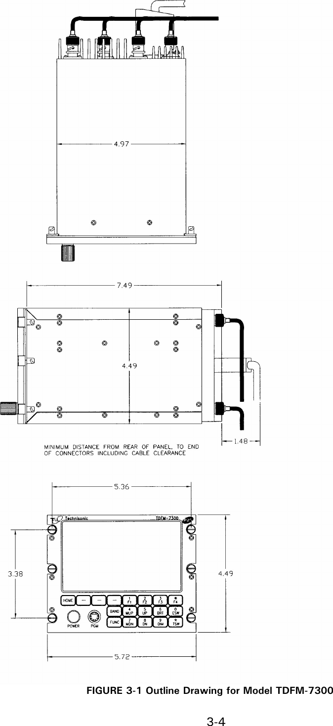
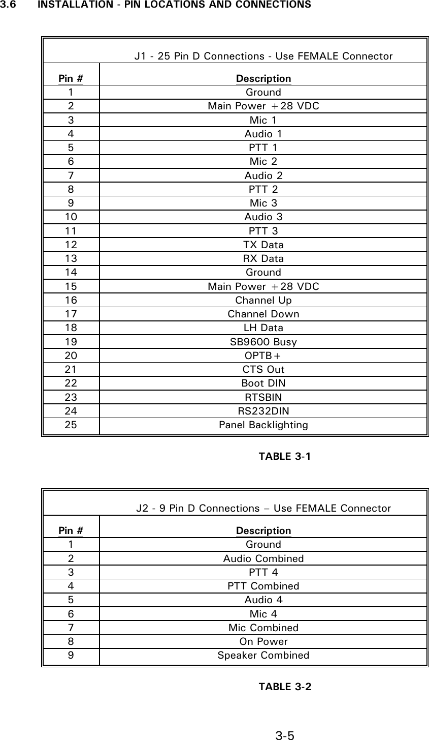
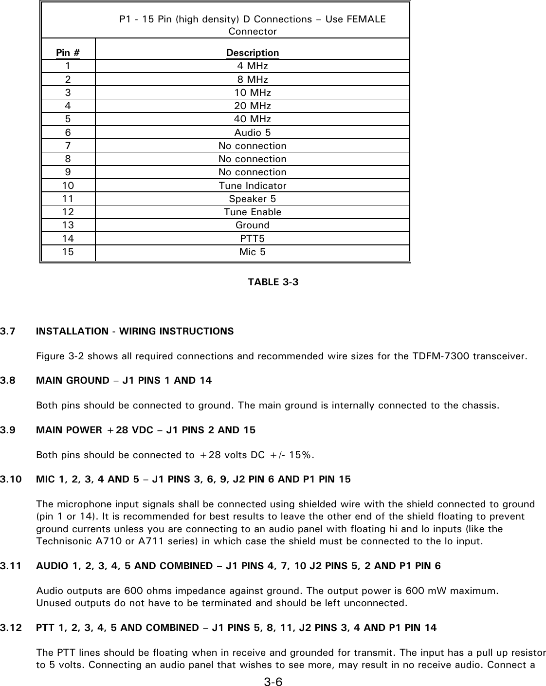
Technisonic TDFM-7300 VHF Low Band Transceiver User Manual TDFM 7300 User s Manual

Technisonic Industries Limited VHF Low Band Transceiver TDFM 7300 User s Manual

User Manual

1-1    AIRBORNE TRANSCEIVER MODEL TDFM-7300     User’s Manual          July 2008       Technisonic Industries Limited 240 Traders Blvd, Mississauga, Ontario L4Z 1W7   Tel:(905) 890-2113  Fax:(905) 890-5338 www.til.ca
1-2  CAUTION  This unit contains static  sensitive devices.  Wear  a  grounded wrist strap and/or  conductive gloves when handling printed circuit boards.    WARNING: This device complies with Part 15 of the FCC Rules. Operation is subject to the following two conditions: (1) this device may not cause harmful interference and (2) this device must accept any interference received, including interference that may cause undesired operation.              NOTE:  This equipment has been tested and found to comply with the limits for a Class B digital device, pursuant to Part 15 of the FCC Rules. These limits are designed to provide reasonable protection against harmful interference in a residential installation. This equipment generates, uses and can radiate radio frequency energy and, if not installed and used in accordance with the instructions, may cause harmful interference with radio communications. However, there is no guarantee that interference will not occur in a particular installation. If this equipment does cause harmful interference to radio or television reception, which can be determined by turning the equipment off and on, the user is encouraged to try to correct the interference by one or more of the following measures: - Reorient or relocate the receiving antenna. - Increase the separation between the equipment and receiver. - Connect the equipment into an outlet on a circuit different from that to which the receiver is connected. - Consult the dealer or an experienced radio/TV technician for help.  Warning:  Changes or modifications not expressly approved by Technisonic Industries could void the users authority to operate the equipment.   WARRANTY INFORMATION  The Model TDFM-7300 Transceiver is under warranty for one year from date of purchase. Failed units caused by defective parts, or workmanship should be returned to:  Technisonic Industries Limited       Technisonic Industries Limited    240 Traders Boulevard          Mississauga,            Amherst, Ontario L4Z 1W7          New York   Tel: (905) 890-2113  Fax: (905) 890-5338    Tel: (716) 691-0669   WARNING  For compliance with FCC RF Exposure Requirements, the mobile transmitter antenna installation shall comply with the following two conditions:  1.  The transmitter antenna gain shall not exceed 3 dBi 2.  The transmitter antenna is required to be located outside of a vehicle and kept at a separation distance of 1 m or more between the transmitter antenna of this device and persons during operation.
1-3    Summary of  DO-160C Environmental Testing for Technisonic Model TDFM-7300 Transceiver.     Conditions   Section   Description of Conducted Tests  Temperature and Altitude   4.0   Equipment tested to categories C4 and D1.  Vibration   8.0   Equipment is tested without shock mounts to categories B, M and N.  Magnetic Effect   15.0   Equipment is class Z.  Power Input   16.0   Equipment tested to category B.  Voltage Spike   17.0   Equipment tested to category B.  RF Emission   21.0   Equipment tested to category Z.     Installation Approval Note  Presently no TSO standard exists for airborne FM transceivers. To make it easier for installation agencies to provide their  customers with an approved  installation supported by an effective  Airworthiness  Approval,  Technisonic  has secured Supplemental Type Certificate (STC) Approvals (both US and Canadian) on its Airborne FM products for many helicopters currently being delivered in the US and Canada as well as a number of fixed wing aircraft. The above referenced  DO-160C test  data is  also  on  file  and  available  from Technisonic to  support  approval requirements  in airframes for which Technisonic does not possess an STC.  Approved aircraft types are listed in the attachments to the formal STC documents. These STC's are the exclusive property of Technisonic and require the written authority of Technisonic for their use. To assist Factory Authorized Technisonic Dealers in the certification process, we have placed copies of our Canadian and US STC's on our web site along with a letter of authorization for their use. These documents may be downloaded and used as support for the technical submission to FAA or Transport Canada. Only factory authorized dealers/installers are permitted to download and make use of these documents on behalf of their customers (end users) in support of regulatory agency approval.  Please refer to the Technisonic web site www.til.ca for the latest issue of available STC=s and letter of authorization for use.
1-4      SECTION 1  GENERAL DESCRIPTION   1.1  DESCRIPTION  The TDFM-7300 is an airborne low band VHF FM transceiver capable of operating between 30 and 50 MHz.  1.2 TECHNICAL CHARACTERISTICS  Specification              Characteristic   Model Designation:            TDFM-7300      Physical Dimensions:            Approx. 3.75" X 5.75" X 8.0”  Weight:              ~6.0 lbs.  (2.7 kg)  Operating Temperature Range:         -30°C to +60°C  Power Requirement: Voltage:            28.0 Vdc, ± 15%   Current:            500mA minimum / 5A maximum    Audio Output Power (including sidetone):      600 mW into 600 ohms      Microphone Inputs:            Carbon or Equivalent      Panel Back Lighting:               Voltage:            28 VDC or 5VAC (selectable)     Current:            10 uA    General      Memory Positions:            200   Tuning Increments:            2.5 kHz   Wide Band Channel Spacing:          20 kHz   Operating Mode:            FM (F3E)   PL / CTCSS Tones:            All Standard Tones RX & TX   DPL / DCS Codes:            All Standard Codes RX & TX   DTMF:                Transmit Encoder Only   Transmitter section             VLO        Frequency range: (MHz)          30 – 50       Power Output: (Watts)           1 or 10 max.       Harmonic Attenuation: (dBc)          -65         FM Hum and noise in dB (wideband):        -40       Audio Distortion:            <5%         Frequency Stability (ppm):          ±2.5       Modulation Limiting            ± 5 kHz
1-5       Receiver section             VLO         Sensitivity: (uV)            0.35       Selectivity: (dB)            -75      Intermodulation: (dB)            -70       Spurious Attenuation: (dB)          -80       Image attenuation: (dB)          -70       Hum and Noise: (dB)            -40       Audio Distortion:            <5%
3-1    SECTION 2 OPERATING INSTRUCTIONS  2.1  GENERAL  A 5-line display and a keypad and a rotary knob provide the operator control of the unit. The knob has multiple functions  including  volume,  and  channel.  The  microphone,  key  line  and  headphone  audio  can  be  wired separately for each of the 4 bands therefore switching from band to band is performed at an audio panel such as the Technisonic A71X series.  2.3  POWER SWITCH  To  switch  the  transceiver  on,  press  and  hold  the  knob  until  the  radio  powers  up.  The  display  will  show TECHNISONIC and the software version installed followed by the model number along with which RF modules are installed. The display will then show the normal display. To switch off the transceiver at any time, press and hold the knob for 2 seconds until the display shows OFF then release. If it is desired that the radio turns on with the radio master in the aircraft, a power jumper may be installed (see installation instructions) such that the radio is always on. The battery master must be used to turn the radio off with this jumper installed.  2.4  KNOB  The knob is a rotary encoder, which turns endlessly, meaning its actual position is not important. The knob also has a push button incorporated in it so you can press the knob as well as turn it. The knob will start out as a volume control. Pressing the knob again will change its function to act as the channel selector. Pressing the knob again causes the keypad function to change from function keys to number keys. The knob in this mode acts as a volume control. Another knob press will bring you to the recall mode. In the recall mode, typing in the channel number will bring you quickly to that channel without scrolling through channels in between. Pressing the knob again brings it back to the volume control mode. The current function of the knob is shown at the bottom right of the display.   2.5  SOFT KEYS AND HOME  The  transceiver  has  three  soft  keys,  which  assume  the  function  shown  on  the  menu  above  them  on the display. Menu items include:   PWR - Selecting PWR will allow the power output of the radio to be set to high or low.  SCAN – Selecting SCAN will invoke the radio to scan the channels previously programmed into the scan list.  FPP  –  Front  Panel  Programming  mode.  Allows  you  to  program  channels  with  TX/RX  frequencies, channel name, tones or codes.  At any time while in one of these functions, you can escape back to the normal mode by pressing the HOME key.
3-2        2.6  FUNC KEY  Pressing the FUNC key will bring up the first functions menu:   F1-F4 = Channels – Pressing one of these keys will load a preprogrammed channel.  4 = Record – Pressing 4 will cause the transceiver to record the next message received on the band selected.    5 = Playback – Pressing 5 will play the last message recorded.  Pressing the FUNC key again will bring up the second menu. The following functions are available:  2 = Configuration – Enters the configuration menu (see 2.18 configuration menu). This is the same menu that can be invoked during boot up.  4 = F1-F4 Programming – Allows you to program a channel and zone to the F1 to F4 keys.   5 = Simplex Repeat – When turned on, the band selected will become a simplex repeater. Simplex repeat (sometimes called parrot repeat) will record an incoming message and immediately retransmit the message on the same frequency.   2.6  MUP AND MDN KEYS (Memory Up and Down Keys)  Pressing these keys allow you to scroll up and down through the 200 available channels. The function of the rotary knob is automatically set to CHAN.   2.8  BRT AND DIM KEYS  Use these keys to dim or brighten the display. The radio powers up at full brightness for normal use but can be dimmed for night operations.
3-3    SECTION 3  INSTALLATION INSTRUCTIONS  3.1  GENERAL  This section contains information and instructions for the correct installation of the TDFM-7300 Transceiver.   3.2  EQUIPMENT PACKING LOG  Unpack the equipment and check for any damage that may have occurred during transit.  Save the original shipping container for returns due to damage or warranty claims.  Check that each item on the packing slip has been shipped in the container.   3.3  INSTALLATION   The TDFM-7300 Transceiver is designed to be Dzus mounted and should be installed in conjunction with an IN-7300  installation  kit.  See  Figure  3-1  for  an  outline  drawing  of  the  unit  with  dimensions  to  facilitate  the installation.   3.4  INSTALLATION KIT - CONTENTS  The IN-7300 installation kit (P/N 059615-1) consists of:   1. One 25 pin Cannon D mating connector (female) complete with crimp pins and hood. 2. One 9 pin Cannon D mating connector (female) complete with crimp pins and hood. 3. 4 BNC connectors.
3-4   FIGURE 3-1 Outline Drawing for Model TDFM-7300
3-5   3.6 INSTALLATION - PIN LOCATIONS AND CONNECTIONS      J1 - 25 Pin D Connections - Use FEMALE Connector   Pin #   Description   1    Ground   2    Main Power +28 VDC   3    Mic 1   4    Audio 1   5    PTT 1   6    Mic 2   7    Audio 2 8  PTT 2 9  Mic 3 10  Audio 3 11  PTT 3 12  TX Data 13  RX Data 14  Ground 15  Main Power +28 VDC 16  Channel Up 17  Channel Down 18  LH Data 19  SB9600 Busy 20  OPTB+ 21  CTS Out 22  Boot DIN 23  RTSBIN   24    RS232DIN   25    Panel Backlighting  TABLE 3-1      J2 - 9 Pin D Connections – Use FEMALE Connector   Pin #   Description   1    Ground   2    Audio Combined   3    PTT 4   4    PTT Combined   5    Audio 4   6    Mic 4   7    Mic Combined 8  On Power   9    Speaker Combined  TABLE 3-2
3-6        P1 - 15 Pin (high density) D Connections – Use FEMALE Connector   Pin #   Description   1    4 MHz   2    8 MHz 3  10 MHz 4  20 MHz 5  40 MHz   6    Audio 5 7  No connection 8  No connection   9    No connection 10  Tune Indicator   11    Speaker 5   12    Tune Enable   13    Ground 14  PTT5   15    Mic 5  TABLE 3-3    3.7  INSTALLATION - WIRING INSTRUCTIONS  Figure 3-2 shows all required connections and recommended wire sizes for the TDFM-7300 transceiver.  3.8  MAIN GROUND – J1 PINS 1 AND 14  Both pins should be connected to ground. The main ground is internally connected to the chassis.  3.9  MAIN POWER +28 VDC – J1 PINS 2 AND 15  Both pins should be connected to +28 volts DC +/- 15%.  3.10  MIC 1, 2, 3, 4 AND 5 – J1 PINS 3, 6, 9, J2 PIN 6 AND P1 PIN 15  The microphone input signals shall be connected using shielded wire with the shield connected to ground (pin 1 or 14). It is recommended for best results to leave the other end of the shield floating to prevent ground currents unless you are connecting to an audio panel with floating hi and lo inputs (like the Technisonic A710 or A711 series) in which case the shield must be connected to the lo input.  3.11  AUDIO 1, 2, 3, 4, 5 AND COMBINED – J1 PINS 4, 7, 10 J2 PINS 5, 2 AND P1 PIN 6  Audio outputs are 600 ohms impedance against ground. The output power is 600 mW maximum.   Unused outputs do not have to be terminated and should be left unconnected.   3.12  PTT 1, 2, 3, 4, 5 AND COMBINED – J1 PINS 5, 8, 11, J2 PINS 3, 4 AND P1 PIN 14  The PTT lines should be floating when in receive and grounded for transmit. The input has a pull up resistor to 5 volts. Connecting an audio panel that wishes to see more, may result in no receive audio. Connect a
3-7  1N4006 diode in series with the cathode towards the audio panel in this case.  3.13  TX DATA AND RX DATA – J1 PINS 12 AND 13  These pins provide RS-232 serial communications for use with the RC-7300 remote control head if installed. Consult the RC-7300 installation manual for details.  3.14  CHANNEL UP AND CHANNEL DOWN – J1 PINS 16 AND 17  These pins can be used to scroll up and down through the zone/channel/mode/talk group selections for the band currently displayed on the screen. The inputs normally floating are grounded to activate. Two push buttons or a center off, SPDT, spring loaded toggle switch are typically used on these inputs. If both pins are grounded simultaneously, the next band will be selected.  3.15  LH DATA, SB9600 BUSY, OPTB+, CTS OUT, BOOT DIN, RTSBIN AND RS232DIN – J1 PINS 18 THROUGH 24  These pins are used for programming or updating the transceiver using Motorola Customer Programming  Software (CPS™) or encryption key loading and are left unconnected. They may be used to update the radio once it is removed from the aircraft. These pins are also brought out to the TDFM-7300’s front panel mini-DIN connector to allow programming in the aircraft.   3.16  PANEL BACKLIGHTING – J1 PIN 25  Connect to aircraft panel dimming bus. The transceiver is capable of supporting 28 VDC or 5 VAC backlighting circuits. Select 28 volts DC or 5 volts AC via the configuration menu (see section 2.18). No damage will occur if the wrong setting is made.  3.17  ANTENNA TUNER CONTROL LINES – P1 PINS 1, 2, 3, 4, 5, 6, 10 AND 12  These connections are to control an antenna tuner system such as the Foxtronics FLX-3050B. Connect according to the manufacturer’s instructions. In the case of the FLX-3050B, the tune indicator which is normally connected to a light, can be connected to pin 10 so that the tuning indication will show on the TDFM-7300 display.  3.18 POWER JUMPER  The radio must be turned on manually each time the avionics bus is switched on. If it is desired that the radio comes on with the radio master in the aircraft, remove the right side panel from the radio and install the supplied 0.1” jumper across JP1 (two pins) near the rear of the radio on the right side of the MCU board. The radio is shipped with the jumper on only one of the two pins. If you attempt to turn off the radio with the jumper installed across the two pins, it will just come back on again in 5 seconds.

Navigation menu