Tecniplast S p A 00038846-0 Gateway User Manual Users manual
Tecniplast S.p.A. Gateway Users manual
Users manual

InstructIons for use

2
Original instructions for use
In case of a disagreement between the translation and the original version of this manual or a notice or disclaimer, the original English version will prevail.
No part of this publication may be reproduced, transmitted, transcribed, stored in a retrieval system, or translated into any language or computer language without the prior written permis-
sion of TECNIPLAST S.p.A.
Technical Support
For technical support, call +39-0332-809711 or send an E- mail to operative-service@tecniplast.it

3
PREFACE
Dear Customer,
This manual is aimed at providing the user with all the information and safety standards required for the correct and safe installation, use and maintenance of the equipment
you have purchased.
Keep the manual in an easily accessible place, known by the Installer, the operator, the supervisor and the service technician who should carefully read it to have a clear
understanding of the installation, use, and maintenance procedures as well as hazardous applications to avoid.
This manual is an integral part of the equipment and should follow it, even in the event of a change of ownership, until nal decommissioning.
Should the manual get damaged or lost, a copy can be requested from TECNIPLAST.
In order to receive technical assistance, spare parts or optional extras not required on order, contact TECNIPLAST and give the equipment serial number, version, and year of
manufacture (see label on the equipment).
The Operator, the Supervisor and the Service Technician must know all the standards reported in this manual before using the equipment or carrying out maintenance
procedures.
COMPANY CONFORMITY TO ENVIRONMENTAL POLICIES
At TECNIPLAST both our production facilities and our end products reect our commitment towards environmental policies in terms of:
• compliance with the principles and contents of current laws and regulations concerning the environment;
• reduction of the environmental impact deriving from our activities, maintaining the right balance between environmental, social and economic responsibilities;
• on-going quest for innovative applications in order to reduce the environmental impact deriving from waste materials, energy consumption and to improve the use of
natural resources and raw materials.
• preventive evaluation of the environmental impact of new plants and processes and improvement of existing ones using all possible and economically sustainable
solutions to increase our environmental performances.
• incentivation and co-responsibility of employees towards this policy by means of adequate training
• use of eective tools to communicate principles and goals of such an environmental policy to our dealers during meetings and training courses;
• dening during the design and development of new products the correct use and dismantling instructions to minimize environmental impact.
Please refer to the link below to download Tecniplast Environmental Responsibility Policy:
http://www.tecniplast.it/en/environmental-responsibility.html.

4

5
Table of Contents
1. GENERAL INFORMATION ......................................................................................................................... 7
1.1 MANUFACTURER’S DETAILS .................................................................................................................................. 7
1.2 TECHNICAL DATA .................................................................................................................................................. 7
1.3 DECLARATION OF CONFORMITY............................................................................................................................. 7
1.3.1 IDENTIFICATION PLATE POSITIONING.......................................................................................................................................7
1.4 RESPONSIBILITY OF THE CUSTOMER .....................................................................................................................7
1.4.1 ELECTRICAL CONNECTION ........................................................................................................................................................7
1.5 UNAUTHORISED MODIFICATIONS .......................................................................................................................... 8
1.6 SPARE PARTS AND TECHNICAL ASSISTANCE ........................................................................................................... 8
1.7 DECOMMISSIONING, FINAL DISMANTLING AND DISPOSAL ...................................................................................... 8
2. SAFETY PRECAUTIONS ............................................................................................................................ 8
2.1 GLOSSARY OF SYMBOLS ....................................................................................................................................... 8
2.2 SAFETY NOTES ..................................................................................................................................................... 9
2.2.1 GENERAL PRECAUTIONS ...........................................................................................................................................................9
2.3 PERSONAL PROTECTIVE EQUIPMENT ..................................................................................................................... 9
3. APPLICATIONS AND WORKING PRINCIPLE ......................................................................................... 10
4. HANDLING .............................................................................................................................................. 11
4.1 PACKAGING ....................................................................................................................................................... 11
4.2 STORAGE ........................................................................................................................................................... 11
5. MAIN FEATURES ..................................................................................................................................... 11
5.1 CONTROL PANEL ................................................................................................................................................ 12
5.2 LEDS STATUS DESCRIPTION ................................................................................................................................ 12
6. INSTALLATION GUIDELINES ................................................................................................................. 13
6.1 PRELIMINARY CHECKS ....................................................................................................................................... 13
7. USAGE ...................................................................................................................................................... 16
7.1 HOW TO CONNECT THE AIR HANDLING UNIT TO THE ONE 2 ONE NETWORK AND REMOTELY CONTROL IT BY MEANS OF A
PORTABLE DEVICE .............................................................................................................................................. 16
7.2 HOW TO DISCONNECT THE AIR HANDLING UNIT FROM THE ONE 2 ONE NETWORK ................................................... 17
7.3 HOW TO CONNECT THE AIR HANDLING UNIT TO THE GUARDIAN SERVER OPTIONAL .............................................. 17
7.4 HOW TO DISCONNECT THE AIR HANDLING UNIT FROM THE GUARDIAN SERVER ...................................................... 17
8. ONE2ONE SOFTWARE MANUAL - GATEWAY SYSTEM FOR AHU ....................................................... 18
8.1 PREFACE ........................................................................................................................................................... 18
8.2 HOME PAGE ....................................................................................................................................................... 19
8.3 SETUP PAGE ....................................................................................................................................................... 20
8.3.1 CAGES SETTING .......................................................................................................................................................................21
8.3.2 ACH/PREVALENCE SETTING ....................................................................................................................................................22

6
8.3.3 DATE/TIME SETTING ...............................................................................................................................................................23
8.3.4 PRESSURE ZEROING PAGE ......................................................................................................................................................24
8.3.5 NIGHT MODE AND SCREEN SAVER SETTING ...........................................................................................................................25
8.4 SETTINGS PAGE .................................................................................................................................................. 26
8.4.1 PASSWORD SETTING...............................................................................................................................................................27
8.4.2 HEPA FILTERS MANAGEMENT .................................................................................................................................................28
8.4.3 TEMPERATURE METRIC SYSTEM SETTING ..............................................................................................................................29
8.4.4 ALARM THRESHOLDS SETTING ...............................................................................................................................................30
8.4.5 AHU SETTING FOR HIGH LEVEL DISINFECTION WITH HYDROGEN PEROXIDE .........................................................................31
8.4.6 LANGUAGE SETTING ............................................................................................................................................................... 32
8.4.7 HOW TO CHANGE THE DEFAULT ONE 2 ONE WIRELESS NETWORK PARAMETERS ...................................................................33
8.5 SERVICE PAGE .................................................................................................................................................... 34
8.6 ALARM PAGE ..................................................................................................................................................... 34
8.6.1 ALARM REPORT PAGES ........................................................................................................................................................... 35
9. ONE2ONE SOFTWARE MANUAL - GATEWAY SYSTEM FOR ISO ......................................................... 36
9.1 PREFACE ........................................................................................................................................................... 36
9.2 HOME PAGE ....................................................................................................................................................... 36
9.3 SETTINGS PAGE .................................................................................................................................................. 37
9.3.1 LANGUAGE SETTING ............................................................................................................................................................... 37
9.3.2 HOW TO CHANGE THE DEFAULT ONE 2 ONE WIRELESS NETWORK PARAMETERS ...................................................................38
9.4 SERVICE PAGE .................................................................................................................................................... 39
9.5 ALARM PAGE ..................................................................................................................................................... 39
9.5.1 ALARM REPORT PAGES ........................................................................................................................................................... 40
10. MAINTENANCE PROCEDURES ............................................................................................................ 41
10.1 GLOSSARY OF SYMBOLS USED IN THE PROCEDURES ............................................................................................ 41
10.2 HOW TO CLEAN THE UNIT .................................................................................................................................. 41
10.2.1 PROCEDURE .......................................................................................................................................................................... 42
11. TROUBLESHOOTING ............................................................................................................................ 42
11.1 PRECAUTIONS ................................................................................................................................................. 42
11.2 ALARMS RAISED BY THE SYSTEM GATEWAY SYSTEM FOR AHU ........................................................................... 42
11.3 WARNING MESSAGES GATEWAY SYSTEM FOR AHU ............................................................................................ 44
11.4 ALARMS RAISED BY THE SYSTEM GATEWAY SYSTEM FOR ISO ............................................................................. 45
11.5 WARNING MESSAGES GATEWAY SYSTEM FOR ISO ............................................................................................ 45

7
1. GENERAL INFORMATION
1.1 MANUFACTURER’S DETAILS
TECNIPLAST S.p.A.
via I Maggio, 6
21020 Buguggiate (VA)
Tel.+39 0332 809 711
Fax+39 0332 458 315
E-mail: operative-service@tecniplast.it
1.2 TECHNICAL DATA
Refer to ANNEX “TECHNICAL SPECIFICATIONS” at the end of this manual for accurate technical information on the machinery. TECNIPLAST S.p.A. reserves the right to modify
the specications to improve the product at any time.
FOR DETAILED INFORMATION ON THE PURCHASED MACHINE, REFER TO THE FACTORY TEST REPORT DOCUMENTATION PROVIDED WITH YOUR MACHINERY.
1.3 DECLARATION OF CONFORMITY
The equipment technical documentation includes the DECLARATION OF CONFORMITY in compliance with EU Equipmentry Directive 2014/53/EU Radio Equipment Directive
(RED).
1.3.1 IDENTIFICATION PLATE POSITIONING
The machine described in this manual is CE marked. The identication plate is mounted on the left hand side of the machine and displays the information hereunder:
1. Name and address of the manufacturer;
2. The machine type and serial number;
3. Year of manufacture.
4. Symbol for the marking of electrical and electronic equipment that indicates separate collection.
1.4 RESPONSIBILITY OF THE CUSTOMER
Unless otherwise specied in the contract conditions, the Client shall supply:
• Electrical supply complete with EARTH in the vicinity of the equipment.
• Optional alarm system to be connected to the alarm dry contacts of the machinery
• Room lighting in compliance with norms and regulations in force in the country of installation.
The Client is responsible for ensuring that all the people working with the machine wear adequate PPE in compliance with national laws and regulations and for carrying out
a risk analysis according to the dierent type of pathogens used during the experiment and for applying all safety measures to avoid contamination.
1.4.1 ELECTRICAL CONNECTION
The equipment is set to work with the voltage and frequency level specied at the time of order and therefore it only accepts those percentage variations, which are standard
in the country of installation.
The equipment is to be connected to the power supply protected by suitable protections in compliance with laws and regulations in force in the country where the machine
is installed.
The use of EARTH compliant to regulations in force in the country where the machine is to be installed is compulsory.
TECNIPLAST disclaims all responsibility for personal or material damage resulting from:
1. Missing or defective earth connection
2. Lack of installation of suitable protections
3. Non-compliance of the power supply with laws and regulations in force in the country where the machine is to be installed.
22It is advisable to connect the equipment to a dedicated power supply line with UPS.
PLUG THE POWER SUPPLY CABLE INTO A SOCKET THAT IS EASILY ACCESSIBLE AT ALL TIMES.

8
1.5 UNAUTHORISED MODIFICATIONS
No modications to the equipment or its components are to be made without written permission from TECNIPLAST.
Unauthorised modications could cause changes to the original functioning and consequently all forms of warranty regarding the entire equipment will be null and void.
The manufacturer is not responsible for any radio or TV interference caused by unauthorized modications to this equipment. Such modications could void the user’s
authority to operate the equipment.
1.6 SPARE PARTS AND TECHNICAL ASSISTANCE
In order to conform with the terms and duration of the Warranty and to ensure perfect inter-changeability, only original TECNIPLAST spare parts are to be used.
Requests for Technical Assistance should be addressed to TECNIPLAST by e-mail, telephone or fax using the numbers listed above this manual.
1.7 DECOMMISSIONING, FINAL DISMANTLING AND DISPOSAL
This product may contain substances that can be hazardous to the environment or to human health not disposed of properly.
Tecniplast is committed to meeting the requirements of the EU directive 2002/96/CE amended by 2003/18/CE on Waste Eletric and Electronic Equipment (WEEE) and,
therefore, promotes “the reuse, recycling and other forms of recovery of such wastes (WEEE) so as to reduce the disposal of waste. It also seeks to improve the environmental
performance of all operators involved in the life cycle of electrical and electronic equipment, e.g. producers, distributors and consumers...”. Tecniplast has worked closely with
its suppliers to eliminate hazardous materials from its products. There are instances, however, where it has not yet been possible to completely eliminate all such materials.
Consequently, some products are labelled with a crossed-out “wheelie” symbol, indicating that special care must be applied to their disposal and / or recycling.
• DO NOT dispose of WASTE ELECTRIC AND ELECTRONIC EQUIPMENT as unsorted municipal waste.
• Waste electric and electronic equipment is to be collected and disposed of separately as per decree 2002/96/CE amended by 2003/108/CE in the European Union or in
compliance to any norm and regulation in force in the country where the equipment is installed.
• Access to the site is controlled and disposal activities are supervised by trained personnel; and records are maintained of the types, approximate quantities and point of
origin of the wastes.
• DO NOT dispose of plastic material as unsorted municipal waste.
• Any plastic material is to be collected and disposed of separately in compliance to any norm and regulation in force in the country where the equipment is installed.
• DO NOT dispose of metallic material as unsorted municipal waste.
• Any metallic material is to be collected and disposed of separately in compliance to any norm and regulation in force in the country where the equipment is installed.
• At the end of life of the product contact your distributor to have information on the collection arrangements.
• It is possible to return, free of charge, other end of life equipment as long as it is of an equivalent type, and has fullled the same function as the supplied equipment.
• Disposal of a product dierent from that described above will be liable to the penalties prescribed by the national provisions in the country where the product is disposed
of.
• Contact Tecniplast to obtain detailed specications and procedures on how to disassemble the equipment.
2. SAFETY PRECAUTIONS
2.1 GLOSSARY OF SYMBOLS
The following words and symbols are used in order to explain safety procedures.
This symbol is used in safety messages and on labels when there is an imminently hazardous situation which, if not avoided, may result in death,
serious injury or serious damage to the system. These safety messages also describe how the hazard can be avoided.
This symbol is used to explain any procedures which, if performed incorrectly, could cause damage to the equipment or potential problems that
might shorten the operating life of the system.
This symbol is used for annotations made for information which requires specic consideration on any procedures, but for which there is no risk
of damaging the system.
Pay special attention to all Safety Warnings given throughout the instructions
For any doubts regarding safety, contact TECNIPLAST.

9
2.2 SAFETY NOTES
2.2.1 GENERAL PRECAUTIONS
Follow all the precautions, procedures and safety measures prescribed by the standards in force to safeguard personal health and read the User’s manual before using the equipment.
Tecniplast disclaims all responsibility for any uses other than those stated in this User Manual unless previously authorised
• Install the product in accordance with the supplied installation instructions.
• The product is suitable for indoor use only. Protect the unit against high humidity and water.
• Do not obstruct air vents.
• Do not attempt to open the product. Avoid mechanical shock.
• Do not use the product if any part is damaged.
• DO NOT carry out modications that might alter the performance or the working conditions of the product. TECNIPLAST disclaims all responsibility for personal injury or
material damage caused by mishandling of the equipment.
• Keep in a cool, well-ventilated place away from sources of ignition.
• DO NOT use the product in an explosive environment.
• Avoid using metallic components - like paper clips, screws and similar - near the product when connected to a power supply, to avoid short circuits due to unwanted
contacts with other board components.
• Check carefully that all cables are correctly connected and that they are not damaged.
• Switch o the unit when not used.
• Operating your device may interfere with medical devices like hearing aids and pacemakers. Please always keep the device more than 20 centimeters away from such
medical devices when they are turned on. Turn your device o if necessary. Consult a physician or the manufacturer of the medical device before using your device.
• The equipment should be set up and used with a distance of approximately 8 inches (20cm) or more to user.
L’équipement doit être installé et utilisé avec une distance d’environ 20 cm (8 pouces) ou plus pour l’utilisateur.
2.3 PERSONAL PROTECTIVE EQUIPMENT
Wear adequate personal protective equipment whenever servicing or cleaning the equipment in compliance with the risk analysis carried out by the customer and with laws
and regulations on personnel health and safety, in force in the country where the machine is installed.
10
The Client is responsible for ensuring that all the people working with the machine wear adequate PPE in com-pliance with national laws and regulations
and for carrying out a risk analysis according to the dierent type of pathogens used during the experiment and for applying all safety measures to avoid
contamination.
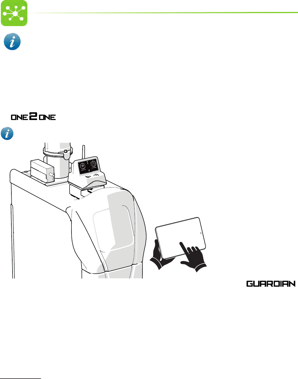
3. APPLICATIONS AND WORKING PRINCIPLE
Tecniplast GATEWAY has been developed to simplify the work of facility managers and operators by providing them with an easy-to-use monitoring of Tecniplast equipment
and machines.
The GATEWAY is to be assembled on TECNIPLAST Air Handling Units1, thus enabling the Air Handling Unit to be remotely controlled:
• by means of a web browser-equipped device (e.g. smartphone, tablet, laptop) directly connected to the unit thanks to the WiFi network generated by the unit:
The unit has been validated with the most common portable devices; the basic requirement is to be compatible with html 5.
• through a server-based application (optional) which allows to remotely control all the Air Handling Units connected to the network: 2
1 Tecniplast GATEWAY is designed to be assembled on Tecniplast Smartow, Easyow, Skyow and Isocage.
2 The WIFLOW has been pre-set for the GUARDIAN application (optional application to be purchased separately).
11
4. HANDLING
4.1 PACKAGING
The equipment and its accessories are shipped as agreed in the order, usually in carton boxes.
Dispose of the packaging in compliance with laws and regulations in force in the country where the equipment is installed.
4.2 STORAGE
The equipment is designed for indoor use only.
Always keep the equipment in a dry place, whether packaged or not.
If the equipment is not deemed to be used, cover it with a piece of cloth or plastic to protect it from dust and store it in an environment compliant with the environmental
requirements specied in Technical data.
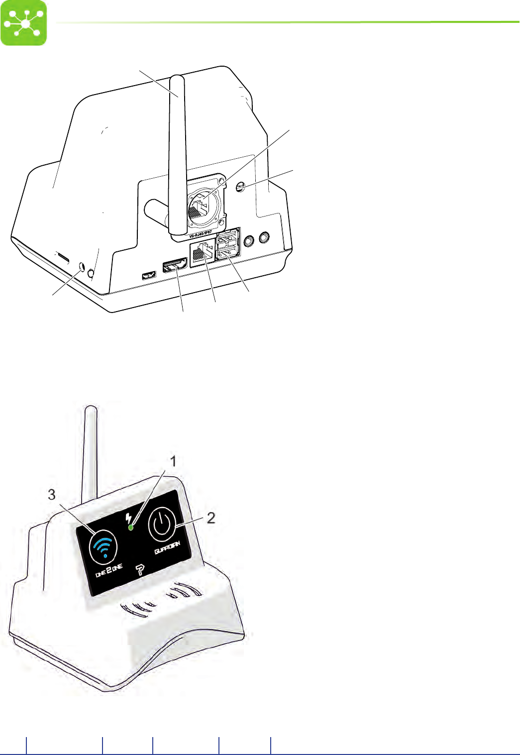
5. MAIN FEATURES
5. RS485 SOCKET
6. POWER SUPPLY CABLE SOCKET
7. GUARDIAN BUOY SOCKET
8. GIGABIT ETHERNET SOCKET
9. HDMI SOCKET
10. RESET BUTTON
11. ANTENNA FOR WIRELESS CONNECTION
12
2
3
4
5
6
1
7
5.1 CONTROL PANEL
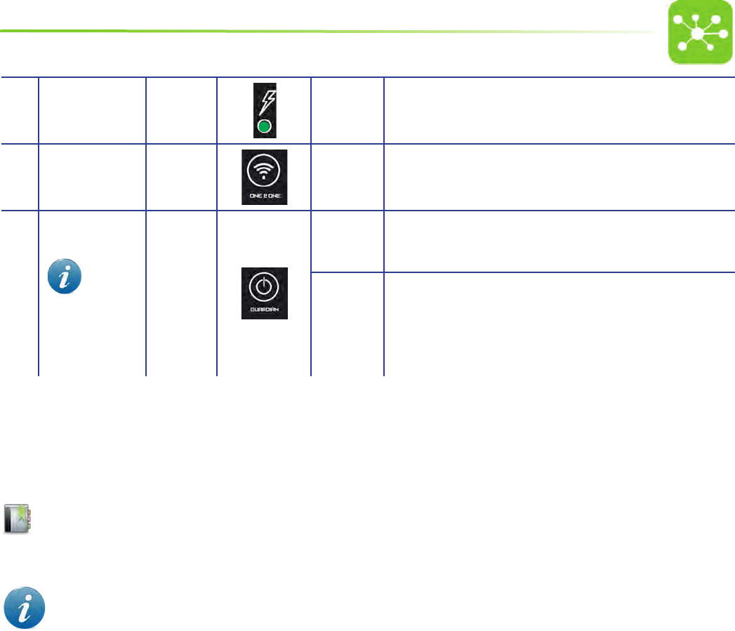
5.2 LEDS STATUS DESCRIPTION
LED COLOUR SYMBOL STATUS LED STATUS EXPLANATION
1. POWER ON LED
2. GUARDIAN LED
3. ONE 2 ONE LED
13
1MAINS GREEN ON/OFF LED ON WHEN GATEWAY IS POWERED
2ONE 2 ONE BLUE STILL* ONE 2 ONE NETWORK GENERATED
3
GUARDIAN
OPTIONAL
This
touchbutton/led is
enabled only if the
Guardian optional
application has been
installed.
GREEN
STILL THE UNIT IS CONNECTED TO THE GUARDIAN SERVER
BLINKING**
COMMUNICATION FAULT. THE UNIT CAN NOT CONNECT TO THE GUARDIAN
SERVER.
Contact Tecniplast authorised Service technicians/lab IT manager
* This led blinks whenever a device is connected to the Network and is reading/writing information, in order to show that the machine is being remotely controlled.
** If the machine is connected to the Guardian server by means of a wireless connection (led still) and the ONE 2 ONE network is enabled, this led starts blinking to show
that the Guardian connection has been disabled until the ONE 2 ONE network is switched o.
6. INSTALLATION GUIDELINES
Refer to the GATEWAY INSTALLATION PROCEDURES supplied for detailed reference on how to install the GATEWAY on your Air Handling Unit.
6.1 PRELIMINARY CHECKS
Images hereunder are purely indicative, refer to the GATEWAY installation procedure for further details.
Once the GATEWAY has been installed on your Air Handling Unit carry out the following preliminary checks:
1. Ensure the power cable is connected (A) and that the power led is on (B).
14
A
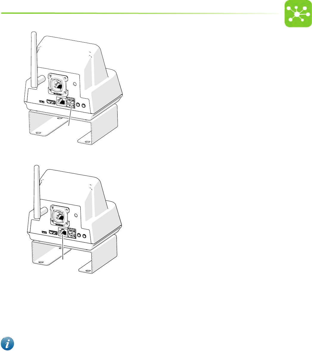
2. Ensure the RJ45 cable is connected to the RS485 port (C).
CC
3. In case the GATEWAY is to be connected to the GUARDIAN SERVER:
• Plug the buoy into it socket (D) following the relevant instructions.
B
15
DD
• In case a wired connection is required, ensure the Ethernet cable (RJ45, E) is plugged into its socket.
EE
• In case a wireless connection is required, screw the antenna into position (F).
16
FF
Refer to the Guardian User guide for the Guardian Software installation/usage.
7. USAGE
7.1 HOW TO CONNECT THE AIR HANDLING UNIT TO THE ONE 2 ONE NETWORK AND REMOTELY CONTROL IT BY MEANS OF A
PORTABLE DEVICE
1. Plug the Air handling Unit to the mains and turn the main switch on. Refer to the Air Handling Unit User Manual.
2. Ensure that the GATEWAY is properly connected and that the power led is on.
3. Switch on your portable device.
4. Keep the ONE 2 ONE button pressed for at least 2 seconds on the Gateway front panel.
A
5. The led will show blue to indicate that the unit is generating the ONE 2 ONE wireless network.
THE WIFI GENERATED NETWORK IS TEMPORARY. IF NOT USED, AFTER 5 MINUTES HAVE ELAPSED THE NETWORK IS AUTOMATICALLY DISABLED. TO
RESTORE THE NETWORK JUST PRESS THE ONE 2 ONE TOUCH BUTTON.
IF NECESSARY THIS OPTION MAY BE DISABLED AND THE WIFI NETWORK CAN BE SET TO INDETERMINED.
6. Connect your portable device to the just generated ONE 2 ONE wireless network (follow your portable device User Guide). Select the network identied by the purchased
machine Serial Number (password: tecniplast).
Carry out this step only the rst time you connect your portable device to the ONE 2 ONE network. Your portable device will connect automatically
to the ONE 2 ONE network afterwards.
To change the default network SSID follow the procedure detailed in paragraph “8.4.7 how to change the default ONE 2 one wireless network
17
PARAMETERS” on page 33.
7. Open your web browser and gain access to any website supporting HTTP protocol. You will be automatically redirected to the Software Home page. Refer to chapter
“8. one2one software manual - gateway system for ahu” on page 18 for Software Usage.
HTTPS protocol is not supported during One 2 One communication.
7.2 HOW TO DISCONNECT THE AIR HANDLING UNIT FROM THE ONE 2 ONE NETWORK
1. Press the ONE 2 ONE button on the Gateway front panel. The touch button led will blink a few times and the ONE 2 ONE network connection will be disabled.
IMPORTANT: IT IS STRONGLY SUGGESTED TO SWITCH OFF THE ONE 2 ONE NETWORK AFTER COMPLETION OF USE IN ORDER TO AVOID GENERATING TOO MANY
NETWORKS INSIDE THE ROOM.
7.3 HOW TO CONNECT THE AIR HANDLING UNIT TO THE GUARDIAN SERVER OPTIONAL
The GATEWAY has been pre-set for the GUARDIAN application. If the application is installed on a Server and the Air Handling Units where the GATEWAY is installed have been
connected to it (by a wired or wireless connection), follow the procedure hereunder to connect to the GUARDIAN Server:
1. Plug the Air handling Unit to the mains and turn the main switch on. Refer to the Air Handling Unit User Manual.
2. Ensure that the GATEWAY is properly connected and that the power led is on.
3. In case a wired connection is required: ensure that the Ethernet cable is properly connected to its port on the GATEWAY rear side.
In case a wireless connection is required:
• ensure the antenna is properly tted on the GATEWAY rear panel.
• ensure a wireless network is available in the area.
IN CASE OF WIRELESS CONNECTION, THE AIR HANDLING UNIT CAN NOT BE CONNECTED TO THE GUARDIAN SERVER AND TO THE ONE 2 ONE NETWORK
AT THE SAME TIME. IF THE GUARDIAN WIFI IS ENABLED AND THE ONE 2 ONE IS ACTIVATED, THE GUARDIAN WILL BE TEMPORARILY DISCONNECTED (LED
BLINKING GREEN).
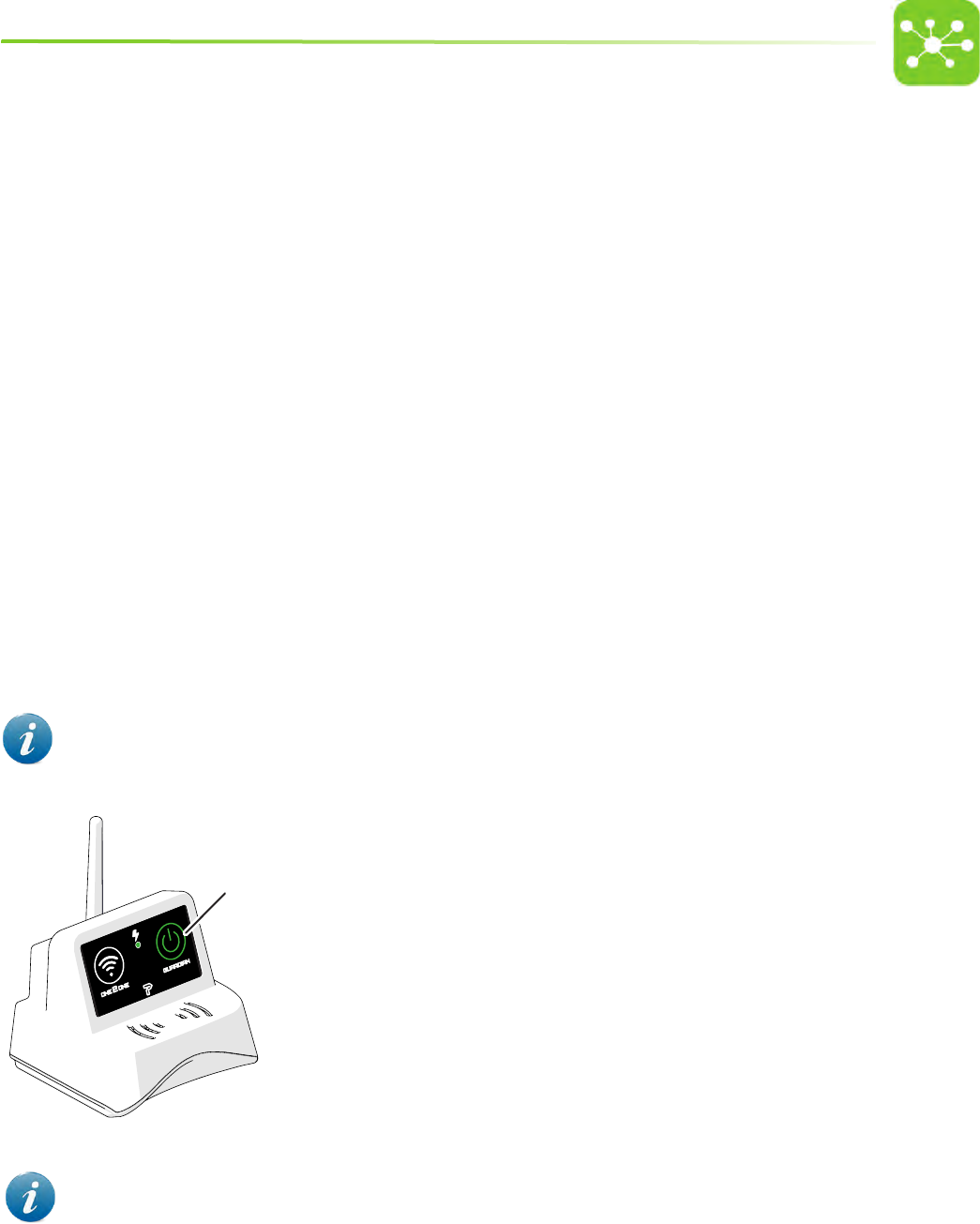
4. If the led is o, keep the GUARDIAN button (A) pressed for at least 2 seconds to connect to the GUARDIAN Server. The GUARDIAN led will show green.
A
5. Read the Guardian User guide for further information on the Guardian Software.
PRIOR TO MOVING ONE UNIT OR SWITCHING IT OFF FOR ANY REASON, IT IS IMPORTANT TO DISCONNECT IT FROM THE GUARDIAN SERVER
SWITCHING OFF THE GUARDIAN BUTTON IN ORDER TO AVOID FALSE ALARM MESSAGES AND NOTIFICATIONS.
7.4 HOW TO DISCONNECT THE AIR HANDLING UNIT FROM THE GUARDIAN SERVER
1. Keep the GUARDIAN button (A) pressed on the Gateway front panel.
NOTE: IF THE LED BLINKS A COMMUNICATION FAULT HAS OCCURRED. THE UNIT CAN NOT CONNECT TO THE
GUARDIAN SERVER.
Contact Tecniplast authorised Service technicians/lab IT manager

18
A
2. Ensure the button led switches o.
3. The Air Handling Unit will immediately disconnect from the GUARDIAN Server.
PRIOR TO MOVING ONE UNIT OR SWITCHING IT OFF FOR ANY REASON, IT IS IMPORTANT TO DISCONNECT IT FROM THE GUARDIAN SERVER IN
ORDER TO AVOID FALSE ALARM MESSAGES AND NOTIFICATIONS.
8. ONE2ONE SOFTWARE MANUAL - GATEWAY SYSTEM FOR AHU
In case of peculiar conguration, such as those with convoluted/long connections, non-symmetrical or non-in-line layouts, an in-eld test with the service monitor cage
(Performance Qualication) should be carried out in order to establish and validate the best settings for that particular conguration.
8.1 PREFACE
The ONE2ONE Software control system allows to access any function and improves and simplies all setting procedures enhancing the exibility of the system.
Although default values are suggested, a simple procedure allows variable customisation to satisfy any specic needs.
19
A double password level denes the boundary between operators, who can set the air handling unit operating mode and supervisors who are entitled to carry out critical
settings for the system.
The software has been designed to be user friendly and most functions are represented by visual symbols, thus making it comprehensible to any user, in spite of the
nationality and spoken language.
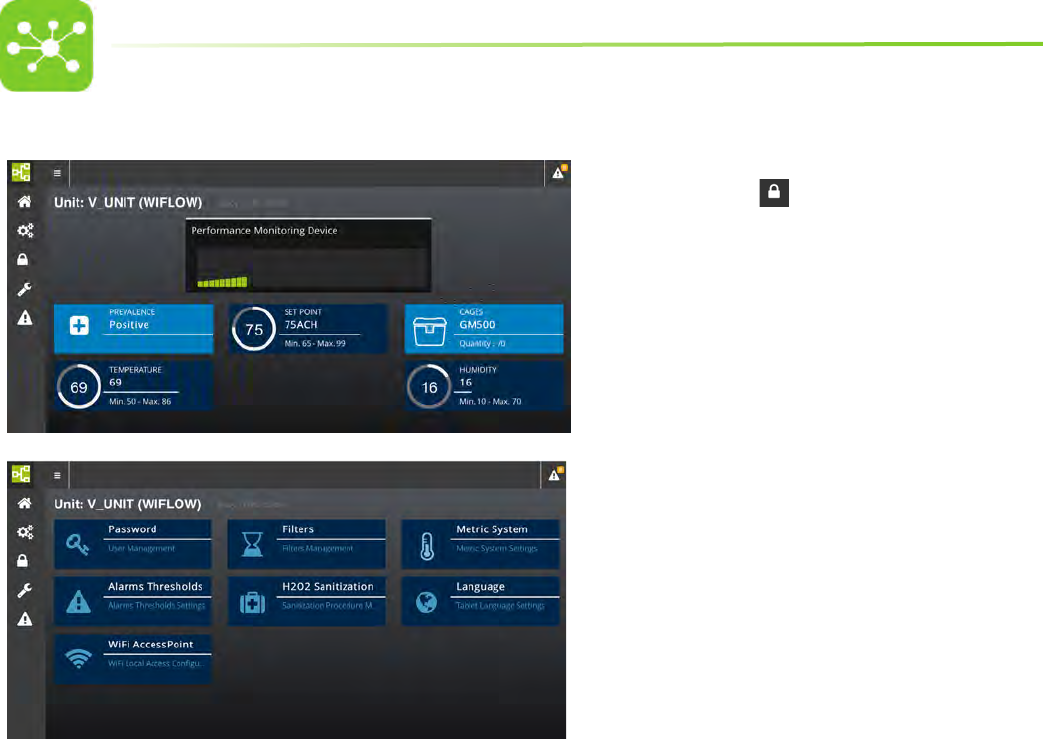
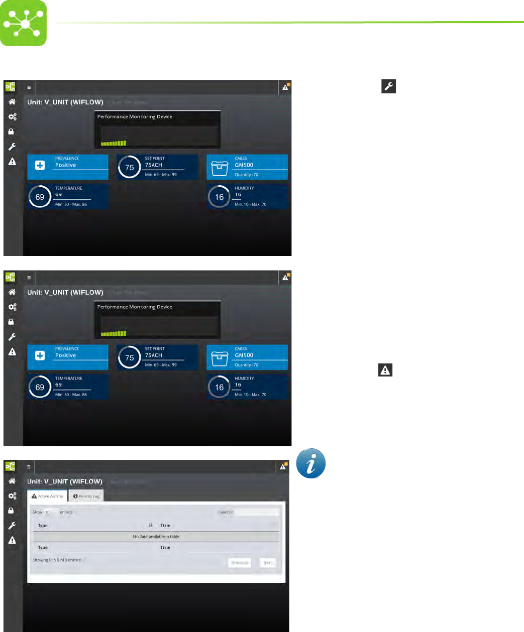
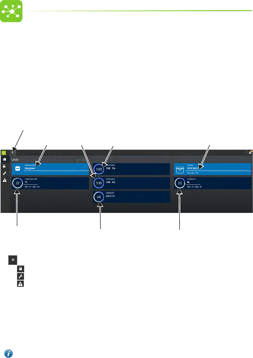
8.2 HOME PAGE
A
BC
DE
F
H
G
I
J
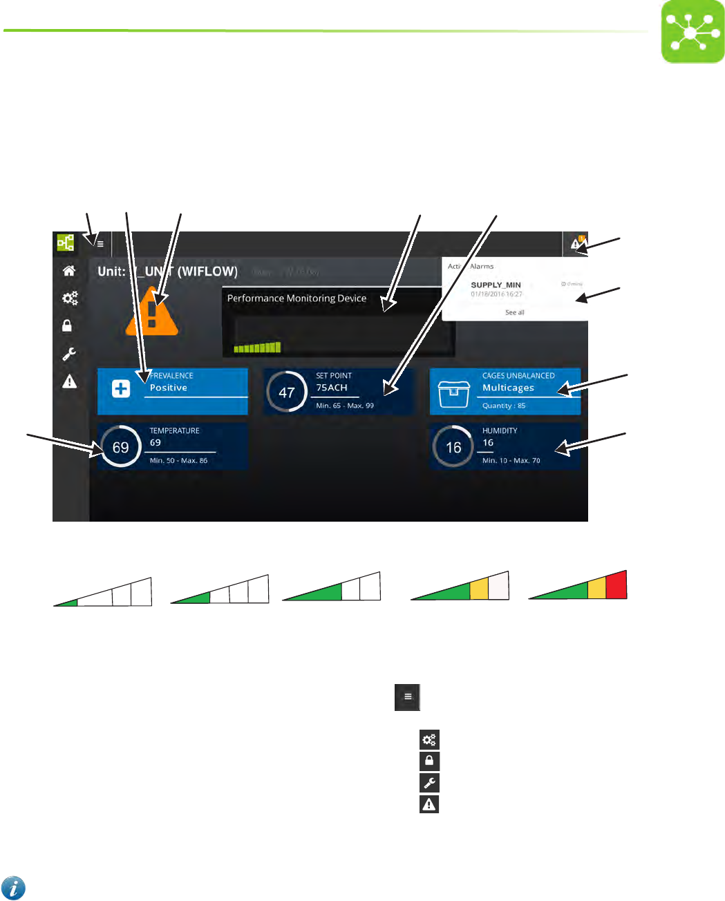
The Home Page displays any relevant information on the air handling unit running conditions in real time:
A. PERFORMANCE INDICATOR PMD
The indicator colours turn progressively from green to red as the HEPA lters gets clogged.
Hepa lter clogging is calculated considering the overall volume of cages connected to the system. The performance indicator shows the status of
the lter which is more clogged between the two lters.
B. PRESSURE OPERATING MODE
C. AIR CHANGES PER HOUR + MINIMUM/MAXIMUM THRESHOLDS
D. TEMPERATURE + MINIMUM/MAXIMUM THRESHOLDS
E. HUMIDITY + MINIMUM/MAXIMUM THRESHOLDS
F. TYPE AND NUMBER OF CAGES CONNECTED TO THE UNIT
G. ALARM NOTIFICATION ICON the number of active alarms is displayed.
Tap the icon to display the alarm banner)
H. ACCESS KEY TO THE HOME PAGE MENU which allows to
monitor and control the air handling unit:
• SETUP PAGE
• SETTINGS PAGE
• SERVICE PAGE
• ALARM PAGE
I. ALARM BANNER in case of current alarms
J. ALARM ICON in case of current alarms
The Home page displays the unit parameters corresponding to the moment when the page was loaded. In case the Home page displays ACH values
dierent from the expected ones or does not show active alarms, it might be necessary to reload the page.
20
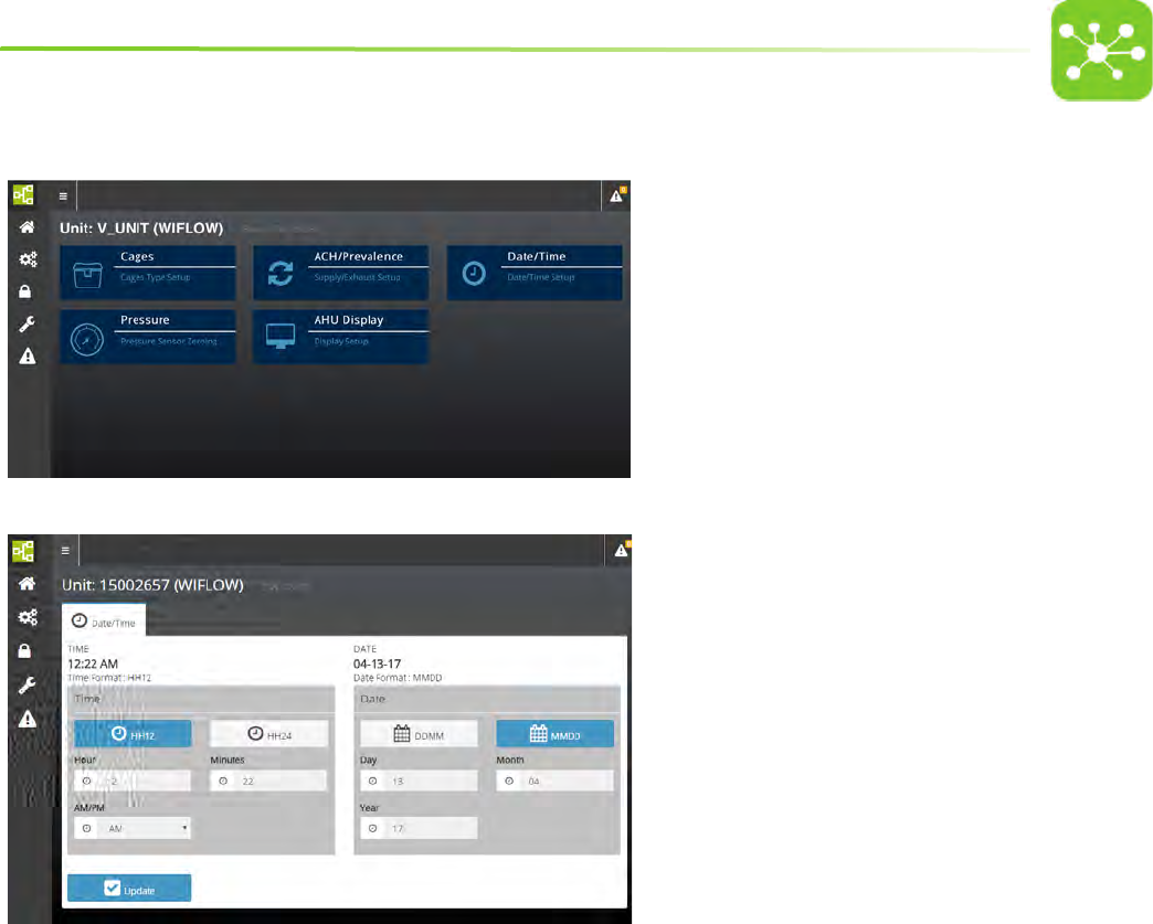
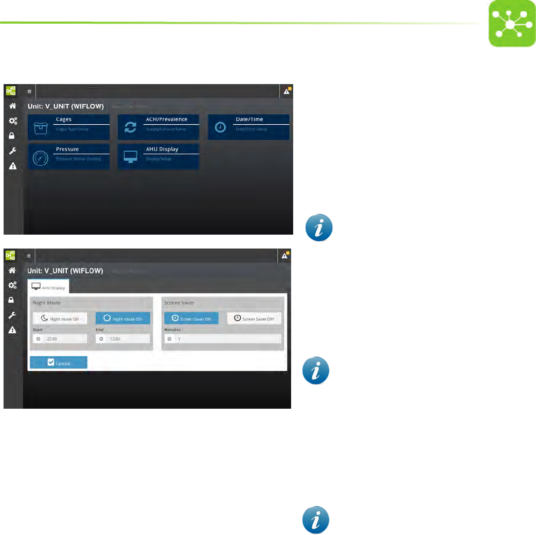
8.3 SETUP PAGE
• Select SETUP from the Home page.
• The system will ask to enter the user password.
• Enter LEVEL 1 password on the numerical keypad to open
the User setting pages
• Tap CAGES to set the number and type of cages connected to
the air handling unit.
• Tap ACH/PREVALENCE to select the Air Handling Unit pressure
mode , set the number of air changes per hour and the
percentage dierential.
• Tap DATE/TIME to set the current date/time
• Tap PRESSURE TEST to access the pressure reading zeroing
page
• Tap AHU/DISPLAY to set the display night mode and screen
saver
21
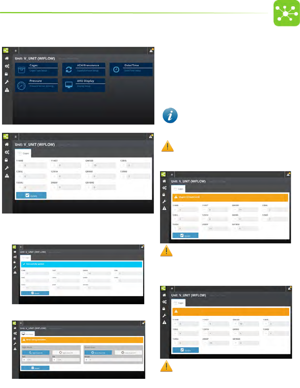
8.3.1 CAGES SETTING
• Tap CAGES from the SETUP page.
• Tap the numerical eld next to the cage type.
• Enter the number of cage positions connected to the system on the
numerical keypad.
• Tap UPDATE* to conrm settings and go on setting other cage types
or go back to the home page.
IN CASE OF MULTIPLE RACKS HOUSING THE SAME TYPE OF CAGES,
ENTER THE TOTAL NUMBER OF CAGE POSITIONS.
If you select cages with dierent volumes, the warning label CAGES
UNBALANCED will appear on the screen to warn of air change dierences
between larger and smaller cages that could arise with such a setting.
If your settings require an airow that exceeds the maximum ow
rate of the system (200 m3 on the SUPPLY UNIT and on the EXHAUST UNIT) the
message
REQUIRED AIRFLOW OUT OF RANGE will be displayed to indicate the
AIRFLOW overload.
Required airflow out of range
If your settings require an airow that is too low for the system the
message REQUIRED AIRFLOW OUT OF RANGE will be displayed to indicate the
AIRFLOW weak load.
The system will not carry on with the setting unless the parameters
are changed.
*SETTINGS CONFIRMATION applicable to all settings)
Once settings have been carried out, the message SUCCESSFULLY APPLIED will be
displayed.
If an error occurs and settings can not be carried out the following message will
be displayed: ERROR DURING EXECUTION
22
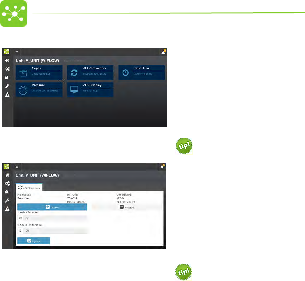
8.3.2 ACH/PREVALENCE SETTING
• Tap ACH/PREVALENCE from the SETUP page.
TO WORK IN POSITIVE PRESSURE MODE:
1. Tap POSITIVE.
2. Enter the supply air changes per hour on the numerical keypad
(Supply - Set Point).
3. Enter the percentage dierential between supply and exhaust ACH
on the numerical keypad (Exhaust - Dierential).
4. Tap UPDATE to conrm
Suggested ACH setting for the machine optimal
functioning in POSITIVE pressure mode:
• 75 ACH
• Percentage dierential between supply and
exhaust: -20%
Suggested values may change according to the cages/
racks connected to the unit or according to specic
Research needs. Contact Tecniplast for further
information.
TO WORK IN NEGATIVE PRESSURE MODE:
1. Tap NEGATIVE.
2. Enter the exhaust air changes per hour on a numerical keypad
(Exhaust - Set Point).
3. Enter the percentage dierential between exhaust and supply ACH
on the numerical keypad (Supply - Dierential).
4. Tap UPDATE to conrm
Suggested ACH setting for the machine optimal
functioning in NEGATIVE pressure mode:
• 75 ACH
• Percentage dierential between exhaust and
supply: -20%
Suggested values may change according to the cages/
racks connected to the unit or according to specic
Research needs. Contact Tecniplast for further
information.
If your settings require an airow that exceeds the maximum ow rate
of the system (200 m3 on the SUPPLY UNIT and on the EXHAUST UNIT) the
message REQUIRED AIRFLOW OUT OF RANGE will be displayed to indicate
the AIRFLOW overload.
If your settings require an airow that is too low for the system the
message REQUIRED AIRFLOW OUT OF RANGE will be displayed to indicate
the AIRFLOW weak load.
23
8.3.3 DATE/TIME SETTING
• Tap DATE/TIME from the SETUP page.
From this page it is possible to choose the date and time format.
Time:
Tap HH12 to enable the 00:00 AM – 11:59 AM, 12:00 PM – 11:59 PM time
format.
Tap HH24 to enable the 00:00 – 23:59 time format.
Date:
Tap DDMM to enable the DD/MM/YY date format.
Tap MMDD to enable the MM/DD/YY date format.
Tap the hour/minutes eld and enter the current time. Select AM/PM in
case the HH12 time format has been set.
Tap the day/month/year eld and enter the current date.
Tap UPDATE to conrm settings.
24
8.3.4 PRESSURE ZEROING PAGE
When the optional pressure TEST CAGE is tted to the rack, it might be necessary to calibrate (zero) the pressure reading.
• Make sure the pressure test cage is properly connected.
• Tap PRESSURE from the SETUP page. Pressure zeroing page is
displayed.
• Disconnect the pressure reader hose from the TEST CAGE.
• Tap RESET PRESSURE VALUE.
• Connect the TEST CAGE and put it back into position.
25
8.3.5 NIGHT MODE AND SCREEN SAVER SETTING
• Tap AHU DISPLAY from the SETUP page.
• NIGHT MODE and SCREEN SAVER page is displayed.
NIGHT MODE SETTING
It is possible to set a time when the touchpad leds turn o (night mode)
in the event that the night activity of the animals housed in the rooms
where the units are installed is disturbed. The leds will automatically turn
on at a pre-set time in the morning thus allowing the Operator to keep all
parameters under control.
If the machine display is in NIGHT MODE or SCREEN SAVER
status, only the POWER ON/OFF led and the ALARM led (in case
of triggered alarms) show. To go back to standard operating
mode just tap the ONE 2 ONE/GUARDIAN touch button.
• Tap NIGHT MODE ON.
• Enter the night mode starting time (hh:mm) in the
START numerical eld.
• Enter the night mode ending time (hh:mm) in the
END numerical eld.
• Tap UPDATE to conrm settings.
TIME SETTING GOES FROM 00:00 TO 23:59. THE SYSTEM IS
NOT ENABLED TO ACCEPT 24:00 AS A SETTING.
SCREEN SAVER SETTING
• Tap SCREEN SAVER ON to enable the screensaver,
OFF to disable it.
• Enter the timespan (minutes) after which the system
leds turn o.
• Tap UPDATE to conrm settings.
THE SCREEN SAVER FUNCTION MAY BE ENABLED ONLY
DURING THE NIGHT MODE. IN CASE THE SCREEN SAVER FUNCTION
IS REQUIRED DURING DAY TIME, SET THE NIGHT MODE FROM 00:00
TO 23:59.
26
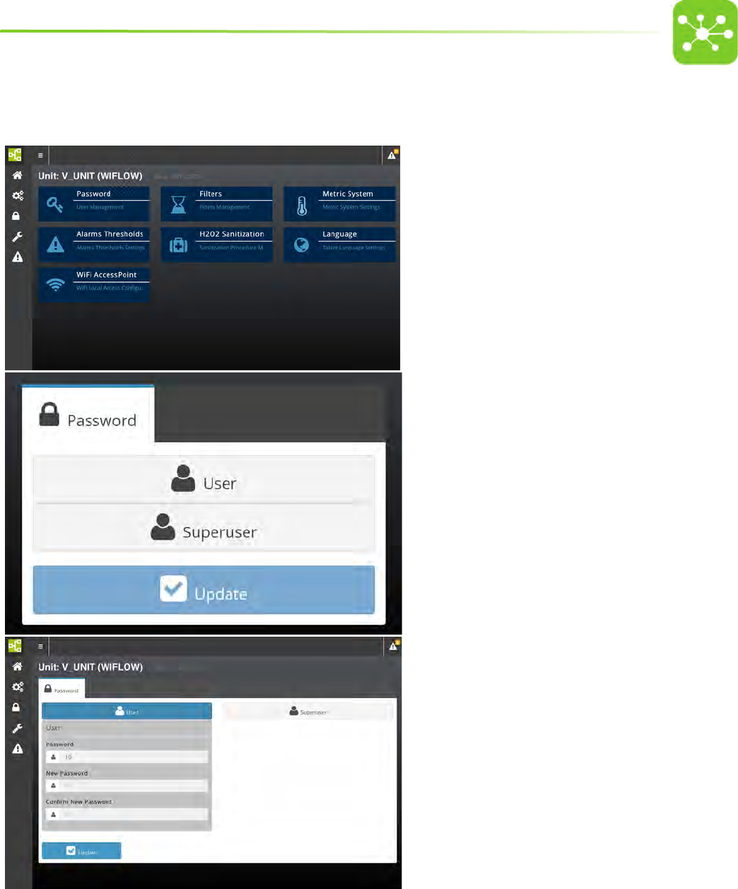
8.4 SETTINGS PAGE
• Select SETTINGS from the Home page.
• The system will ask to enter the user password.
• Enter LEVEL 2 password on the numerical keypad to open
the Super user settings page.
• Tap PASSWORD to change the default Password.
• Tap FILTERS to check the HEPA lters lifespan and to reset the
lters residual lifetime after lter replacement.
• Tap METRIC SYSTEM to set the desired temperature metric
system (°C or °F)
• Tap ALARM THRESHOLDS to set the minimum and maximum
alarm thresholds.
• Tap H2O2 SANITIZATION to set the H2O2 cycle
• Tap LANGUAGE to set the desired language
• Tap WIFI ACCESSPOINT to change the default wireless nework
SSID (Service Set Identier)
27
8.4.1 PASSWORD SETTING
• Tap PASSWORD from the SETTING page.
• Tap the password level you wish to change: USER or SUPERUSER
and tap UPDATE to conrm.
• Enter the old password and conrm.
• Enter the new password and conrm.
• Enter the new password again and conrm.
28
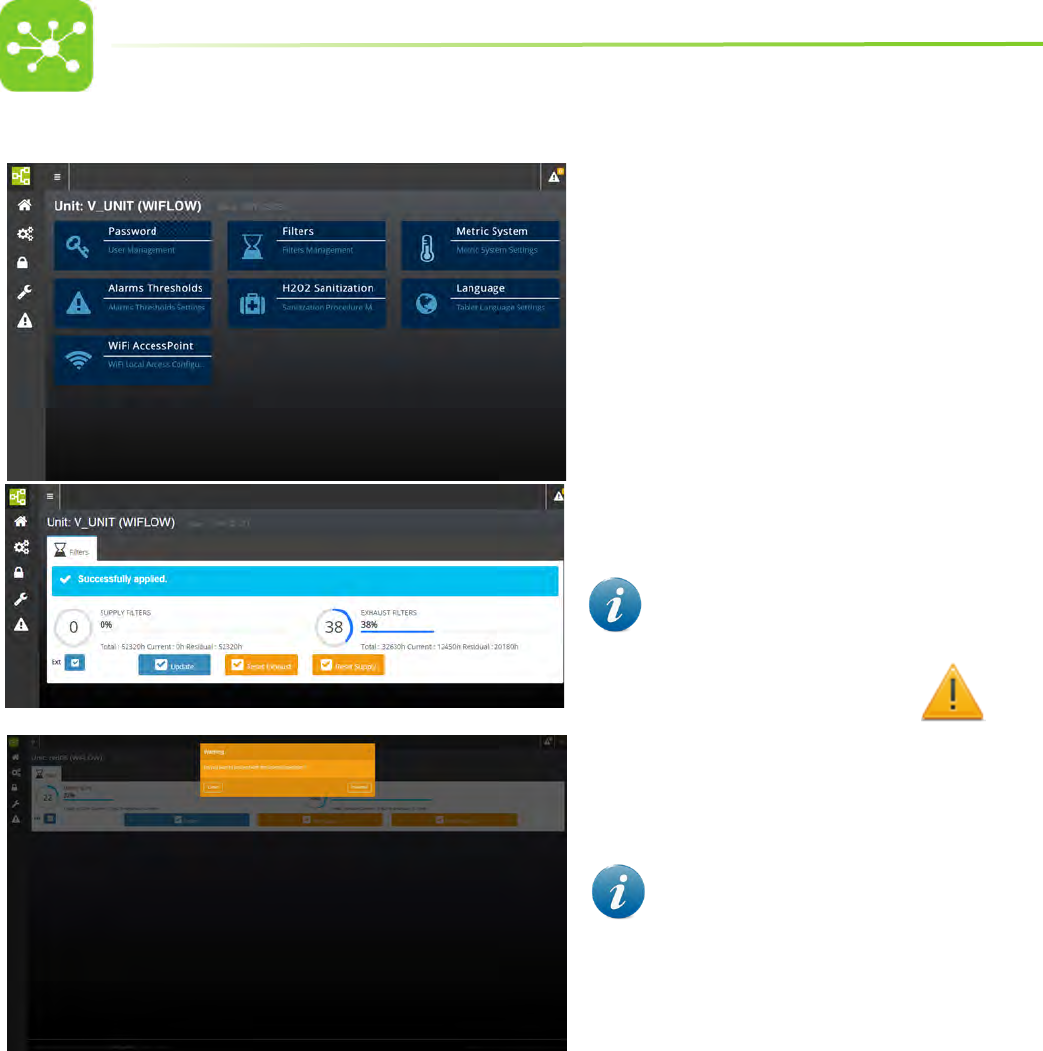
8.4.2 HEPA FILTERS MANAGEMENT
• Tap FILTERS from the SETTING page.
• The HEPA FILTERS management page is displayed. From
this page it is possible to check the HEPA lter lifespan and
to reset the lter residual lifetime after the HEPA lter has
been replaced.
• To reset the counter, press RESET SUPPLY or
RESET EXHAUST.
• Tap PROCEED to conrm the operation. The new lter
residual lifetime is displayed (Residual).
• Flag EXT to enable the unit to send the alarm to the
machine touchpad, to the ONE 2 ONE interface and to the
(optional) alarm remote system.
If EXT is not agged the system will only display the
alarm on the touchscreen and log the message in the alarm log
page. The ALARM LED on the machine touchpad will
not show.
The Total life eld displays the machine operating life.
720 hours before the date when one of the two HEPA
lters is to be replaced, the home page displays a banner.
Open the Service page to acknowledge which lter needs to
be replaced.
29
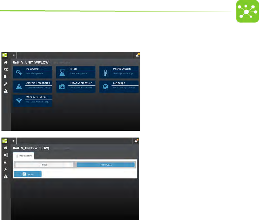
8.4.3 TEMPERATURE METRIC SYSTEM SETTING
• Tap METRIC SYSTEM from the SETTING page.
• The TEMPERATURE METRIC SYSTEM SETTING PAGE is displayed.
• Tap the desired temperature metric system: International System
of Units (°C) or Imperial System or British Imperial (°F).
• Tap UPDATE to conrm settings.
30
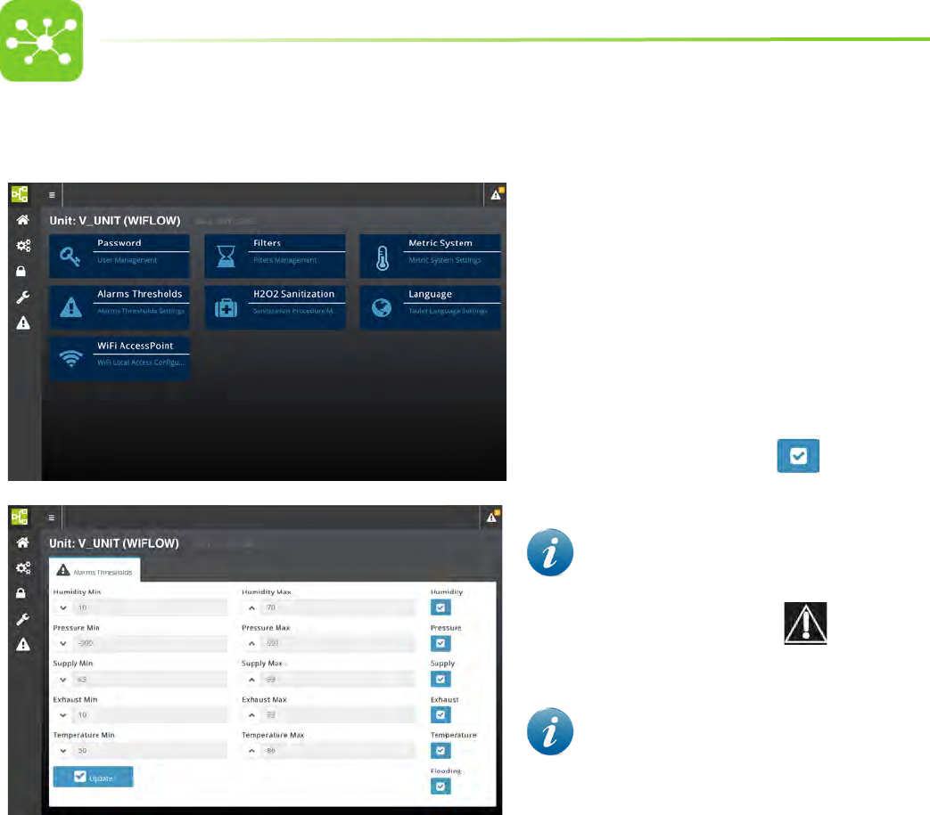
8.4.4 ALARM THRESHOLDS SETTING
• Tap ALARMS THRESHOLDS from the SETTING page.
• The ALARMS THRESHOLDS SETTING PAGE is displayed. From this
page it is possible to set the minimum and maximum alarm
thresholds for SUPPLY AND EXHAUST AIR FLOW, HUMIDITY,
PRESSURE and TEMPERATURE.
• To change the default alarm thresholds, tap the numerical eld
next to the value you wish to change and enter the new value from
the input page.
• Flag the blue box next to each alarm to enable the unit
to send the alarm to the machine touchpad, to the ONE 2 ONE
interface and to the (optional) alarm remote system.
If EXT is not agged the system will only display the alarm
on the touchscreen and log the message in the alarm log page.
The ALARM LED on the machine touchpad will not show.
• Tap UPDATE to conrm settings.
The system has no control on TEMPERATURE and HUMIDITY
levels inside the cage. It is simply set to monitor values and send
an alarm whenever these values are lower or exceed the set ones.
31
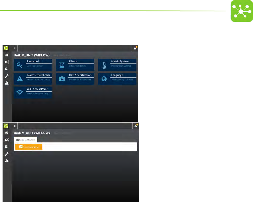
8.4.5 AHU SETTING FOR HIGH LEVEL DISINFECTION WITH HYDROGEN PEROXIDE
The following settings are to be carried out whenever it is necessary to perform a high level disinfection cycle of the air handling unit using hydrogen peroxide.
• Tap H2O2 SANITIZATION from the SETTING page.
• The H2O2 SANITIZATION page is displayed.
• Tap START SANITIZATION to setup the air handling unit for high
level disinfection.
• The air handling unit will automatically set the supply and
exhaust airow values needed to carry out the disinfection
cycle.
• As soon as the air handling unit has reached the pre-set
airow velocities on both the supply and exhaust modules it
is possible to start the cycle.
• Follow the gas generator instruction manual to carry out the
cycle.
• As soon as the cycle is over, switch o the unit and switch it on
again to go back to the home page and the pre-set ACH.
32
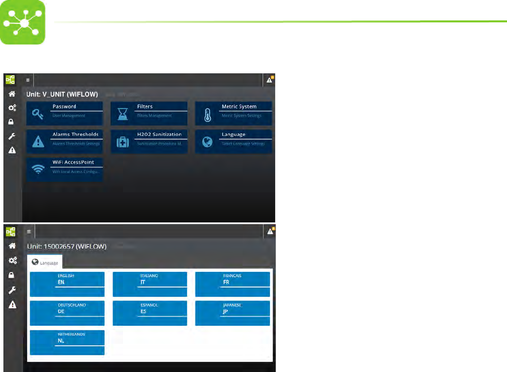
8.4.6 LANGUAGE SETTING
• To change the language displayed by the system, tap LANGUAGE
from the SETTING page.
• The LANGUAGE SETTING page is displayed.
• Tap the desired language.
33
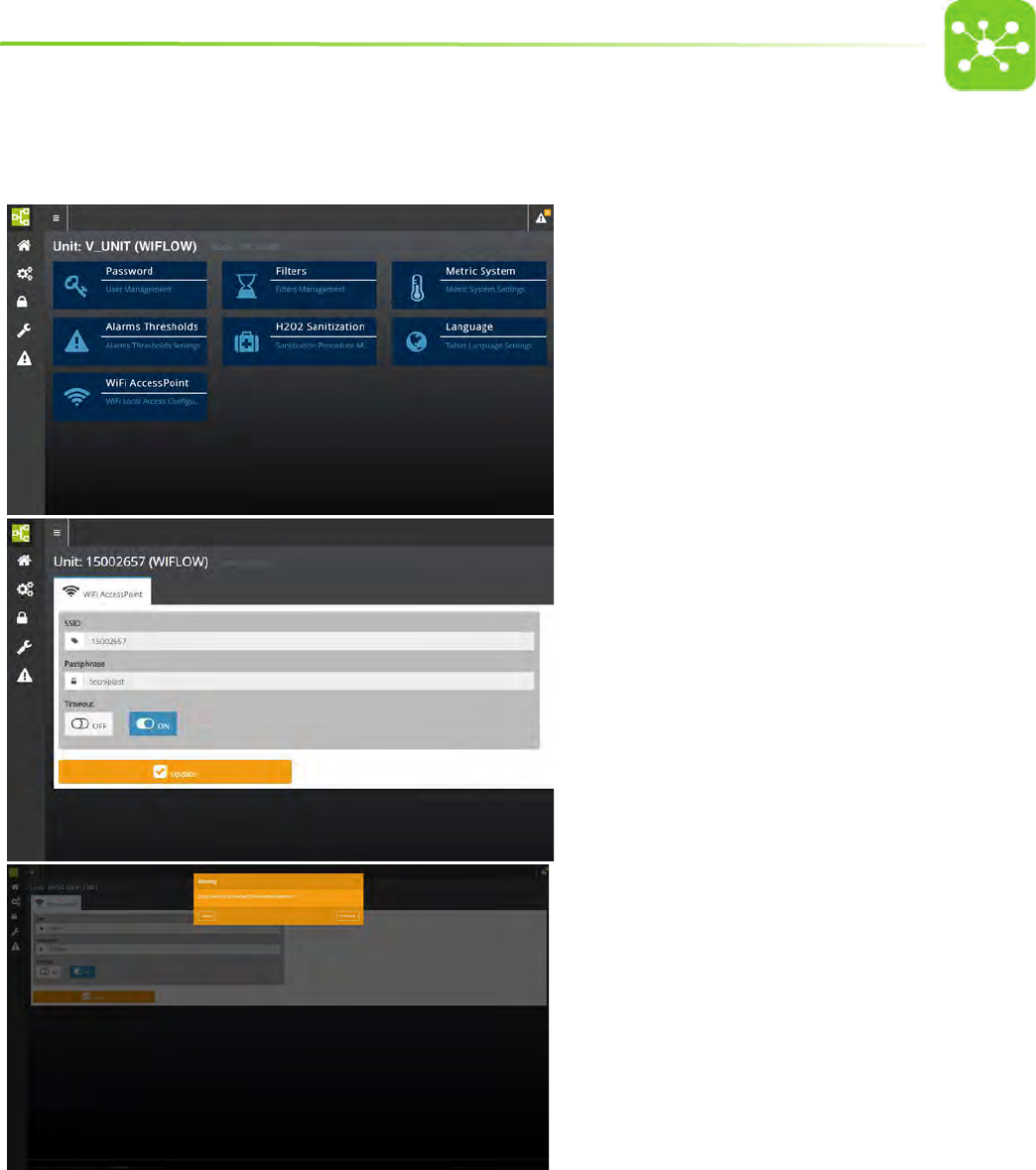
8.4.7 HOW TO CHANGE THE DEFAULT ONE 2 ONE WIRELESS NETWORK PARAMETERS
To change the deafult SSID carry out the following procedure:
• Tap WiFi ACCESS POINT from the SETTING page.
• Enter the new SSID (Service Set IDentier).
• If you want to set a password for the WiFi network, enter the new
local WIFI PASSWORD.
• TIMEOUT:
Select ON if you want the WiFi network to switch o automatically
after 5 minutes.
Select OFF if you do not want the WiFi netwotk to switch o
automatically. In this case the WiFi will switch o after 5 minutes
have elapsed without any user interaction with the network.
• Tap UPDATE to conrm settings.
• Tap PROCEED to conrm the operation.
34
8.5 SERVICE PAGE
• Select SETTINGS from the Home page.
• The system will ask to enter the SERVICE password.
• Access to SERVICE page is reserved to qualied and fully
trained TP technicians.
8.6 ALARM PAGE
• Select ALARMS from the Home page.
• A page with a list of all active alarms is displayed.
• Tap PREVIOUS/NEXT to scroll alarm pages.
Whenever the system triggers an alarm, the alarm icon on
the page top shows that a new alarm has been triggered. Tap the alarm
icon to display the current alarm. An alarm notication is displayed also
on the Home page.
35
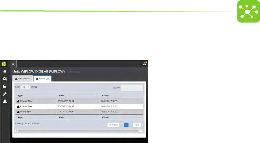
8.6.1 ALARM REPORT PAGES
• Tap ALARMS LOG from the ALARM PAGE to open the ALARM REPORT page.
The screen displays the list of all alarms with the date and time when the alarm occurred and when it was closed. Tap PREVIOUS/NEXT to scroll alarm pages.
See the troubleshooting for a complete list of all alarm and warning messages displayed by the system.
36
9. ONE2ONE SOFTWARE MANUAL - GATEWAY SYSTEM FOR ISO
In case of peculiar conguration, such as those with convoluted/long connections, non-symmetrical or non-in-line layouts, an in-eld test with the service monitor cage
(Performance Qualication) should be carried out in order to establish and validate the best settings for that particular conguration.
9.1 PREFACE
The ONE2ONE Software control system allows to access any function and improves and simplies all setting procedures enhancing the exibility of the system.
Although default values are suggested, a simple procedure allows variable customisation to satisfy any specic needs.
A double password level denes the boundary between operators, who can set the air handling unit operating mode and supervisors who are entitled to carry out critical
settings for the system.
The software has been designed to be user friendly and most functions are represented by visual symbols, thus making it comprehensible to any user, in spite of the
nationality and spoken language.
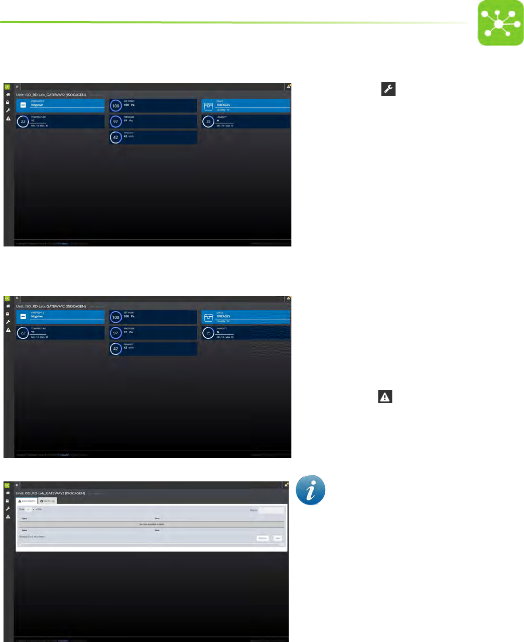
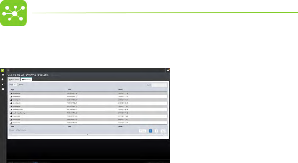
9.2 HOME PAGE
Gateway Iso Evo
3
A
BD
C
E
F
G
H
The Home Page displays any relevant information on the air handling unit running conditions in real time.
A. ACCESS KEY TO THE HOME PAGE MENU which allows to monitor and control the air handling unit:
• SETTINGS PAGE
• SERVICE PAGE
• ALARM PAGE
B. PRESSURE OPERATING MODE READ ONLY Please refer to the Guardian User Manual to carry out the current setting)
C. PRESSURE SET POINT Pa) READ ONLY Please refer to the Guardian User Manual to carry out the current setting)
D. TYPE AND NUMBER OF CAGES CONNECTED TO THE UNIT READ ONLY Please refer to the Guardian User Manual to carry out the current setting)
E. TEMPERATURE + MINIMUM/MAXIMUM THRESHOLDS READ ONLY Please refer to the Guardian User Manual to carry out the current setting)
F. CURRENT PRESSURE Pa) READ ONLY)
G. HUMIDITY + MINIMUM/MAXIMUM THRESHOLDS READ ONLY Please refer to the Guardian User Manual to carry out the current setting)
H. EXHAUST AIR FLOW (READ ONLY)
The Home page displays the unit parameters corresponding to the moment when the page was loaded. In case the Home page displays exhaust
air ow values (m3/h)dierent from the expected ones or does not show active alarms, it might be necessary to reload the page.
37
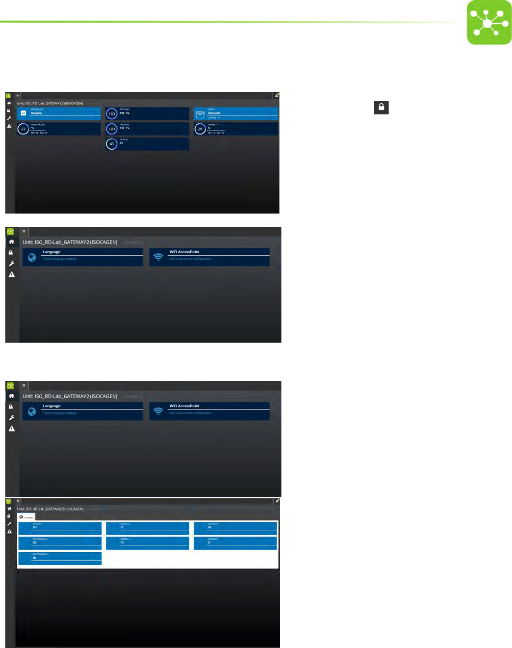
9.3 SETTINGS PAGE
m3/h
• Select SETTINGS from the Home page.
• The system will ask to enter the user password.
• Enter LEVEL 2 password on the numerical keypad to open
the Super user settings page.
• Tap LANGUAGE to set the desired language
• Tap WIFI ACCESSPOINT to change the default wireless nework
SSID (Service Set Identier)
9.3.1 LANGUAGE SETTING
• To change the language displayed by the system, tap LANGUAGE
from the SETTING page.
• The LANGUAGE SETTING page is displayed.
• Tap the desired language.
38
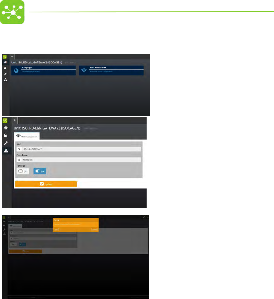
9.3.2 HOW TO CHANGE THE DEFAULT ONE 2 ONE WIRELESS NETWORK PARAMETERS
To change the deafult SSID carry out the following procedure:
• Tap WiFi ACCESS POINT from the SETTING page.
• Enter the new SSID (Service Set IDentier).
• If you want to set a password for the WiFi network, enter the new
local WIFI PASSWORD.
• TIMEOUT:
Select ON if you want the WiFi network to switch o automatically
after 5 minutes.
Select OFF if you do not want the WiFi netwotk to switch o
automatically. In this case the WiFi will switch o after 5 minutes
have elapsed without any user interaction with the network.
• Tap UPDATE to conrm settings.
• Tap PROCEED to conrm the operation.
39
9.4 SERVICE PAGE
• Select SETTINGS from the Home page.
• The system will ask to enter the SERVICE password.
• Access to SERVICE page is reserved to qualied and fully
trained TP technicians.
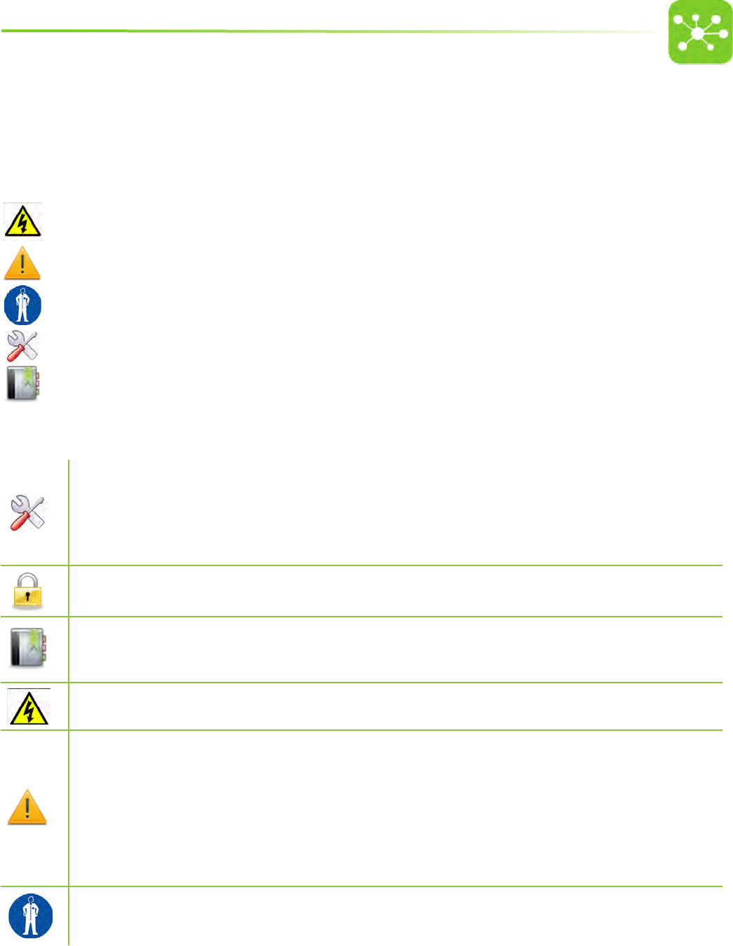
9.5 ALARM PAGE
• Select ALARMS from the Home page.
• A page with a list of all active alarms is displayed.
• Tap PREVIOUS/NEXT to scroll alarm pages.
Whenever the system triggers an alarm, the alarm icon on
the page top shows that a new alarm has been triggered. Tap the alarm
icon to display the current alarm. An alarm notication is displayed also
on the Home page.
40
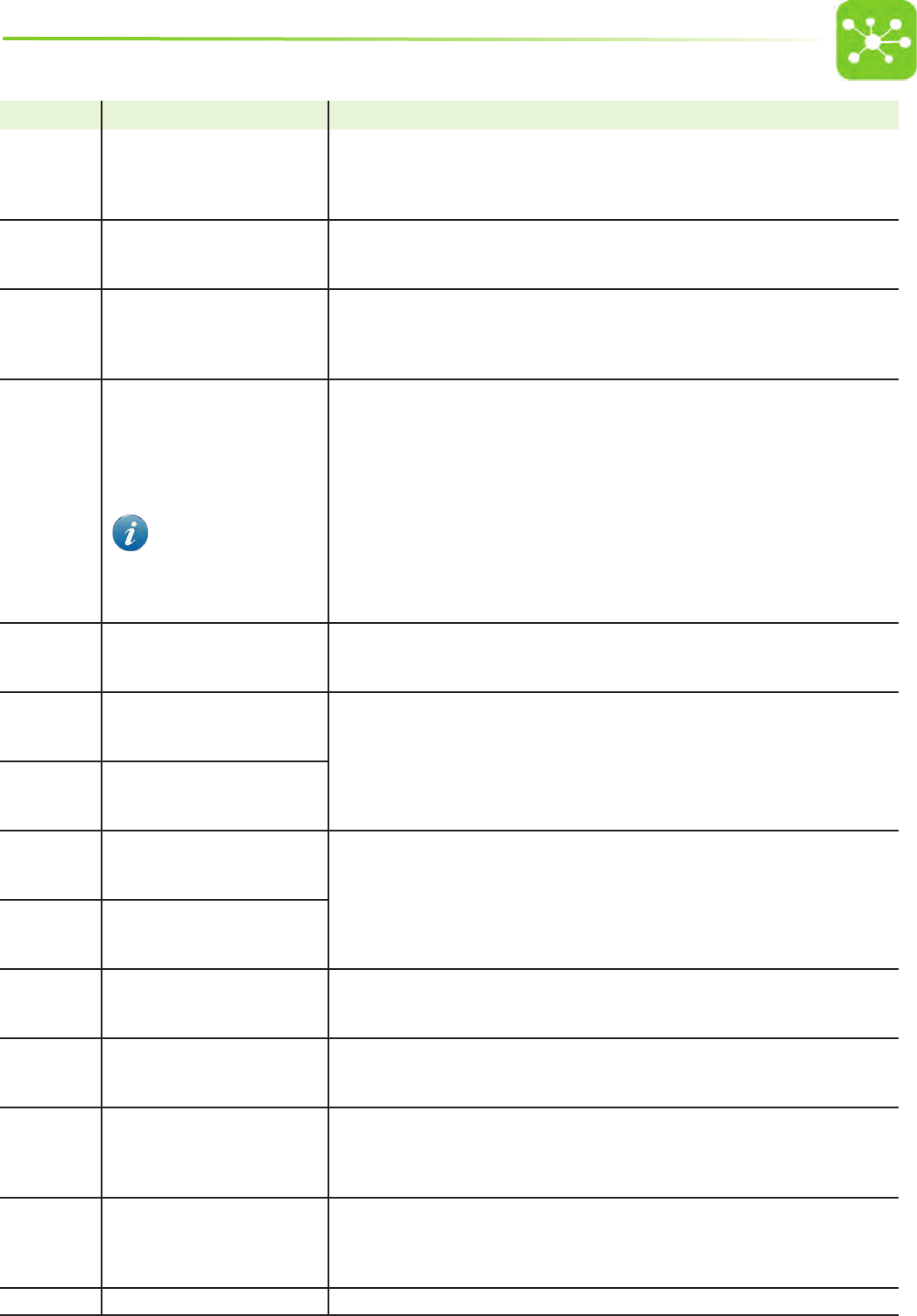
9.5.1 ALARM REPORT PAGES
• Tap ALARMS LOG from the ALARM PAGE to open the ALARM REPORT page.
The screen displays the list of all alarms with the date and time when the alarm occurred and when it was closed. Tap PREVIOUS/NEXT to scroll alarm pages.
See the troubleshooting for a complete list of all alarm and warning messages displayed by the system.
41
10. MAINTENANCE PROCEDURES
10.1 GLOSSARY OF SYMBOLS USED IN THE PROCEDURES
Symbols are used throughout the following paragraphs to draw attention on critical operations, tools and equipment needed to carry out the procedure, personal protective
equipment etc.:
ELECTRICAL HAZARD
GENERAL DANGER/WARNING/CAUTION
PERSONAL PROTECTIVE EQUIPMENT REQUIRED TO CARRY OUT THE MAINTENANCE PROCEDURE
TOOLS AND EQUIPMENT NEEDED TO CARRY OUT THE PROCEDURE
REFERENCES
10.2 HOW TO CLEAN THE UNIT
One anti-static detergent suitable for plastic surfaces (ABS + polycarbonate)
Demineralised water
1 rellable pump atomizer for water
1 rellable pump atomizer for detergent
1 rellable pump atomizer for demineralised water
Anti-static cloth wipers (eg. soft, microber cleaning cloth)
The following procedure may be safely performed by a trained operator.
Laboratory SOPs
Laws and regulations on personal health and safety in force in the country where the machine is installed.
Detergent Technical Specications
DO NOT USE LIQUID OR STEAM JETS NEAR ELECTRICAL COMPONENTS.
Disconnect the unit from the mains before cleaning.
DO NOT use ethyl alcohol, caustic soda, bleach, ammonia to clean the master plastic surfaces.
DO NOT use alkaline detergents.
DO NOT use abrasive cleaners, scouring pads or strong oxidizing agents.
Read the detergent technical specications to settle the most appropriate contact time.
Do not ush the machinery and electrical components with water! This may cause irreversible damage to the machinery and its components.
DO NOT use abrasive cloths, paper towels, or tissue paper to clean the touchscreen.
Keep the device dry. If it gets wet, immediately unplug it and allow it to dry.
The GATEWAY unit is not autoclavable.
Wear adequate personal protective equipment in compliance with your Laboratory SOPs and with laws and regulations in force in the country where the
machine is installed in terms of personal health and protection.
WEAR HEAVY DUTY PVC OR RUBBER GLOVES

42
10.2.1 PROCEDURE
PLASTIC SURFACES:
1. Disconnect the Gateway from the power supply.
2. Take a wiper, spray it with warm water and clean the Gateway plastic cover.
3. Take the specic anti-static detergent solution atomiser, spray it on an antistatic soft cloth wiper and clean the Gateway plastic cover.
4. Leave some time for the detergent to carry out its chemical action (refer to the detergent technical specications to settle the most appropriate contact time).
5. Using a wiper sprayed with demineralised water rinse the Gateway and dry it.
6. Wipe the control panel with a dry soft cloth.
11. TROUBLESHOOTING
FOR ANY ANOMALIES NOT LISTED IN THE FOLLOWING PAGES, CONTACT TECNIPLAST
All maintenance actions on this machine must be performed by a competent, qualied and fully trained technician. Tecniplast provides specic courses to train qualied
personnel for the maintenance required for this machine. All the qualied personnel is identiable by a “Service Qualication Certicate” issued by Tecniplast.
Tecniplast disclaims all responsibility in case the maintenance actions are performed by not qualied personnel.
As per the “Standard Terms e Conditions”, in order for the manufacturer’s warranty to remain valid for the full period, a routine maintenance must be performed by competent,
qualied and fully trained personnel at the recommended intervals.
11.1 PRECAUTIONS
When servicing the equipment, the Service Technician must display warning signs which clearly indicate that the machine is being serviced.
Service Technicians must follow all safety measures and precautions specied for personal health and safety, in particular apparel must comply with the safety
requirements in force in the country in which the machine is installed.
Keep unauthorised people away from the operating area and the equipment when servicing the equipment.
11.2 ALARMS RAISED BY THE SYSTEM GATEWAY SYSTEM FOR AHU
Whenever an alarm is triggered, safety conditions are no longer guaranteed.
Refer to the Air Handling Unit User Manual for further details on raised alarms and solutions.
43
CODE N. ALARM MESSAGE CAUSE AND SOLUTION
1
MIN. SUPPLY FLOW
Supply ow does not reach the
minimum set threshold.
Check supply air inlet is not obstructed
Check prelter is not clogged
Check HEPA lter is not clogged.
Call Tecniplast Authorised Service Technician.
2
MAX. SUPPLY FLOW
Supply ow exceeds the maximum set
threshold.
Check all openings are capped.
Call Tecniplast Authorised Service Technician.
3
MIN. EXHAUST FLOW
Exhaust ow does not reach the
minimum set threshold.
Check Exhaust air outlet is not obstructed
Check prelter is not clogged.
Check HEPA lter is not clogged.
Call Tecniplast Authorised Service Technician.
4
MAX. EXHAUST FLOW
Exhaust ow exceeds the maximum
set threshold.
Check all openings are capped.
If the case, check that the connection between the exhaust air release and the centralised building
exhaust system is not airtight.
Call Tecniplast Authorised Service Technician.
5
MIN. PRESSURE ALARM
This section applies only when
the optional pressure check is tted
Check minimum pressure alarm threshold setting.
Check that the Supply Unit air inlet is not closed
Check that he clamps of the TEST CAGE are fastened.
Check whether an extraneous item has been trapped between the TEST CAGE and its top.
Check that the TEST CAGE is in its position.
Check that the pressure reader hose is properly connected.
Calibrate pressure reading.
6
MAX.PRESSURE ALARM
Pressure exceeds the maximum
threshold set in the SET ALARMS page
Check maximum pressure alarm threshold setting
Check air outlet of the EXHAUST UNIT is open.
7
MIN. TEMPERATURE
Temperature does not reach the
minimum threshold
Check environment temperature settings.
Call Tecniplast Authorised Service Technician.
8
MAX. TEMPERATURE
Temperature exceeds the maximum
threshold
9
MIN. RH%
Humidity does not reach the minimum
threshold
Check environment humidity settings.
Call Tecniplast Authorised Service Technician.
10
MAX. RH%
Humidity exceeds the maximum
threshold
11
REPLACE SUPPLY HEPA
Supply HEPA has reached expiry date
and must be replaced
Replace Supply HEPA lter
12
REPLACE EXHAUST HEPA
Exhaust HEPA has reached expiry date
and must be replaced
Replace Exhaust HEPA lter
13
SUPPLY AIR FLOW ALARM
Supply air ow does not reach the
target value set in the ACH SET page
Check supply air inlet is not obstructed
Check prelter is not clogged
Check HEPA lter is not clogged.
Call Tecniplast Authorised Service Tecnician.
14
EXHAUST AIR FLOW ALARM
Exhaust air ow does not reach the
target value set in the ACH SET page
Check Exhaust air outlet is not obstructed
Check prelter is not clogged.
Check HEPA lter is not clogged.
Call Techniplast Authorised Service Technician.
20 HARDWARE FAULT
Call Techniplast Authorised Service Technician.
44
CODE N. ALARM MESSAGE CAUSE AND SOLUTION
16
FLOODING
The LDS sensor has detected a ooding
inside the cage.
Gain access to the LDS Brain software and check which cage/s has raised the alarm.
Check if there is any water inside the cage.
Call Tecniplast Authorised Service Technician.
11.3 WARNING MESSAGES GATEWAY SYSTEM FOR AHU
Warning messages are displayed in the alarm page but are not recorded in the alarm report page.
MESSAGE CAUSE SOLUTION
SUPPLY HEPA WARNING
EXHAUST HEPA WARNING
30 days before the date when one of
the two HEPA lters is to be replaced,
the home page displays a blinking red
logo corresponding to the expiring lter
and the alarm page shows a warning
message: SUPPLY HEPA WARNING or
EXHAUST HEPA WARNING
If HEPA lters are not replaced after the
expiry date, the system will trigger an
alarm and the screen will display the
alarm mode page.
Get in touch with the authorised service technician and make arrangements to
replace the lter.
Keep the lter lifespan monitored in order to replace it before it expires.
CAGES UNBALANCED
This banner will appear on the screen to
warn of air change dierences between
larger and smaller cages that could arise
with such a setting.
It is advisable to change cage conguration so as to make the air distribution inside
cages uniform.
AIRFLOW OVERLOAD
Required airflow out of range
Whenever the user sets a volume that
exceeds the maximum ow rate of the
system (200 m3 on the SUPPLY UNIT
and on the EXHAUST UNIT), the banner
REQUIRED AIRFLOW OUT OF RANGE will
be displayed, to warn the user that the
system will not carry on with the setting
unless the parameters are changed to a
suitable value.
Decrease air volume setting.
AIRFLOW WEAK LOAD
Required airflow out of range
Whenever the user sets a number of
cages that is too low for the system to
handle, the banner REQUIRED AIRFLOW
OUT OF RANGE will be displayed to warn
the user that the system will not carry on
with the setting unless the parameters
are changed to a suitable value.
Increase number of set cages.
45
11.4 ALARMS RAISED BY THE SYSTEM GATEWAY SYSTEM FOR ISO
Whenever an alarm is triggered, safety conditions are no longer guaranteed.
Refer to the Air Handling Unit User Manual for further details on raised alarms and solutions.
CODE N. ALARM MESSAGE CAUSE AND SOLUTION
1
MIN PRESSURE Pressure does not reach the minimum set threshold.
The supply air inlet is clogged.
2
MAX PRESSURE
Pressure inside cages exceeds the maximum set threshold.
The exhaust air outlet is closed
The Control Cage is not into its position.
The clamps of the control cage are not fastened.
3
AIRFLOW
The airow rate does not reach the minimum set.
The supply HEPA lter is clogged.
The exhaust HEPA lter is clogged.
The cages HEPA lter is clogged
The supply pre-lter is clogged.
The exhaust pre-lter is clogged.
Either or both fans are faulty.
4
SUPPLY HEPA The set life span of the Supply HEPA lter has expired
5
EXHAUST HEPA The set life span of the Exhaust HEPA lter has expired
6
UPS BATTERY LOW The UPS battery level is lower than the minimum set
7
UPS FAULT The UPS is faulty
8
MIN. TEMPERATURE
Temperature does not reach the minimum threshold
Check environment temperature settings
Call Tecniplast Authorised Service Technician.
9
MAX. TEMPERATURE
Temperature exceeds the maximum threshold
Check environment temperature settings
Call Tecniplast Authorised Service Technician.
10
MIN. RH% Check environment humidity settings
Call Tecniplast Authorised Service Technician
11
MAX. RH%
11.5 WARNING MESSAGES GATEWAY SYSTEM FOR ISO
Warning messages are displayed in the alarm page but are not recorded in the alarm report page.
MESSAGE CAUSE SOLUTION
SUPPLY HEPA WARNING
EXHAUST HEPA WARNING
30 days before the date when one of
the two HEPA lters is to be replaced,
the home page displays a blinking red
logo corresponding to the expiring lter
and the alarm page shows a warning
message: SUPPLY HEPA WARNING or
EXHAUST HEPA WARNING
If HEPA lters are not replaced after
the expiry date, the system will trigger
an alarm and the screen will display the
alarm mode page.
Get in touch with the authorised service technician and make arrangements to
replace the lter.
Keep the lter lifespan monitored in order to replace it before it expires.

46

47

2-00041425-01

TECHNICAL SPECIFICATIONS
I DIMENSIONS AND WEIGHT
W x D x H 123 x 139 x 141 mm
NET WEIGHT 500 g
II POWER SUPPLY AND UTILITIES
VOLTAGE
230V - 50/60Hz
MAX LINE POWER ABSORPTION < 180 W
115V - 50/60Hz
MAX LINE POWER ABSORPTION < 180 W
100V - 50/60Hz
MAX LINE POWER ABSORPTION < 180 W
ETHERNET CABLE RJ45 MAXIMUM LENGTH 3m
III OPERATING ENVIRONMENTAL REQUIREMENTS
ALTITUDE Up to 2000m
OPERATING TEMPERATURE 5°C to 40°C
HUMIDITY 80% at 31°C decreasing linearly to 50% relative humidity at 40°C.
POLLUTION DEGREE II
OVER VOLTAGE CATEGORY II As per IEC60364-4-443
IV NETWORK SPECIFICATIONS
ONE 2 ONE WIRELESS NETWORK
WIFI NETWORK STANDARD 802.11 g - 2,4 GHz
WIFI PROTECTION WPA, WPA2 (optional)
PORTABLE DEVICE REQUIREMENT Access to web browser. The unit has been validated with the most common portable devices; the
basic requirement is html 5
GUARDIAN WIRELESS NETWORK
NETWORK INFRASTRUCTURE Good WIFI coverage (802.11 g - 2,4 GHz) or Ethernet socket
PORTABLE DEVICE REQUIREMENT Access to web browser
V TECHNICAL SPECS
COVER MATERIAL ABS + POLYCARBONATE
• USB port (for buoy connection only)
• MicroSD (for servicing purposes)
• Serial Data Port
• Gigabit Ethernet Connector
• Compatible with 802.11g WiFi @ 2.4GHz
• Integrated access point 802.11g WiFi @ 2.4GHz
2-00041455-01
The following Technical Data refer to standard unit and are to be considered indicative.
TECNIPLAST reserves the right to modify the specifications to improve the product at any time.

TECHNICAL SPECS 2-00041455-01
VI COMPLIANCE TO STANDARDS AND DIRECTIVES
2014/35/EU
Low Voltage Directive
2014/53/EU
Radio Equipment Directive (RED)
IEC 62368-1
Audio/video, information and communication technology equipment - Part 1: Safety requirements
2014/30/EU
Electromagnetic Compatibility Equipment Directive
EN 61326-1:2013
ETSI EN 301 489-1 V1.9.2:2011 ETSI EN 301 489-17 V2.2.1:2012
EN 62311:2008
FCC 47 Cft. Part 15 B:2010, FCC 47 Cft. Part 15 B clause 15.107: conducted emissions, FCC 47 Cft. Part 15 B clause 15.109: radiated emissions
This device complies with Part 15 of the FCC Rules. Operation is subject to the following two conditions: (1) this device may not cause harmful interference, and (2)
this device must accept any interference received, including interference that may cause undesired operation.
NOTE: The manufacturer is not responsible for any radio or TV interference caused by unauthorized modifications to this equipment. Such modifications could void the
user’s authority to operate the equipment.
NOTE: This equipment has been tested and found to comply with the limits for a Class B digital device, pursuant to Part 15 of the FCC Rules. These limits are designed to
provide reasonable protection against harmful interference in a residential installation.
This equipment generates, uses and can radiate radio frequency energy and, if not installed and used in accordance with the instructions may cause harmful interference
to radio communications. However, there is no guarantee that interference will not occur in a particular installation. If this equipment does cause harmful interference
to radio or television reception, which can be determined b turning the equipment off and on, the user is encouraged to try to correct the interference by one or more
of the following measure:
• Reorient or relocate the receiving antenna
• Increase the separation between the equipment and receiver
• Connect the equipment into an outlet on a circuit different from that to which the receiver is connected.
• Consult the dealer or an experienced radio/TV technician for help.
The device complies with Industry Canada licence-exempt RSS standard(s).
Operation is subject to the following two conditions:
(1) this device may not cause interference, and (2) this device must accept any interference, including interference that may cause undesired operation of the device.
Le présent appareil est conforme aux CNR d’Industrie Canada applicables aux appareils radio exempts de licence. L’exploitation est autorisée aux deux conditions sui-
vantes: (1) l’appareil ne doit pas produire de brouillage, et (2) l’utilisateur de l’appareil doit accepter tout brouillage radioélectrique subi, même si le brouillage est
susceptible d’en compromettre le fonctionnement.
VII PACKAGING DETAILS
PACKAGING DETAILS
TYPE CARTON BOX
QUANTITY 1
WIDTH 260 mm
DEPTH 170 mm
HEIGHT 180 mm
WEIGHT 0,50 kg