Tecom Co AW4042UN 11N WLAN ADSL Router User Manual AW4042U QIG v2
Tecom Co Ltd 11N WLAN ADSL Router AW4042U QIG v2
Tecom Co >
Manual
- 1 -
Quick Installation Guide
AW4042U
4-Ethernet Port ADSL/ADSL2+ WiFi CPE
1. Install AW4042U
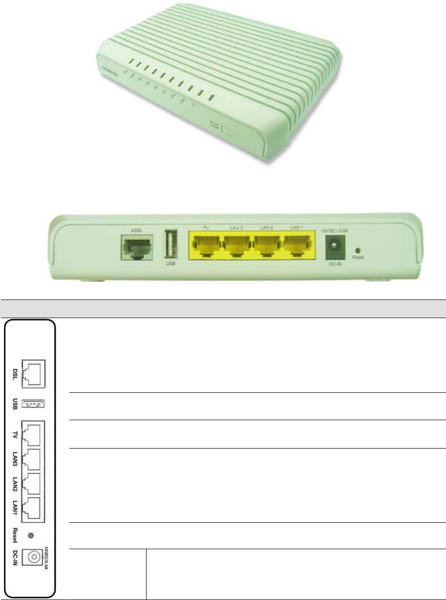
Back Panel
Fig. 1.1 the Back Panel of AW4042U
Label Function
DSL
RJ-45 connector: WAN interface to connect DSL line
USB USB 2.0 connector: for printer and ext. Memory support
TV RJ-45 connector: Connect to the PC Ethernet port, or to STB
LAN 1- 3 RJ-45 connector: Connect to the PC Ethernet port.
RST Reset button: Reset AW4042U to factory default setting.
DC-IN Connect to the supplied power converter cable
Table 1.1 Illustration of AW4042U Back Panel
- 2 -
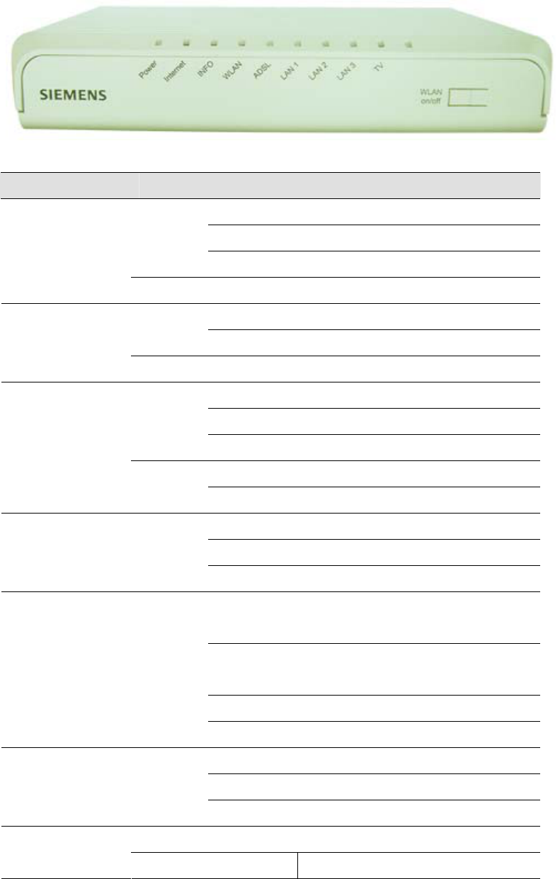
Front Panel
There are 8 LEDs on the front panel which indicate the status of AW4042U showing as below:
Fig. 1.2 the Front Panel of AW4042U
Label Color Signalling Function
Flashing System start-up
Lighted Active connection
Green
Off Power-off / General MODEM error
POWER
Red Lighted Factory reset / FW updating
Lighted Active data session
Green Flashing Data transmission
INTERNET
Red Lighted No DSL correct user data
Flashing PPPoE authentication ongoi
Lighted PIN OK and active PPPoE Session
Green
Flashing Data transmission
Lighted Waiting Pin insertion
INFO
Red
Flashing PIN OK, waiting authentication
Lighted Wireless on
Flashing Data transmission
WLAN Green
Off Wireless off
Slow
Flashing
sending pilot tones
Fast
Flashing
DSL training
Lighted DSL synchronized
DSL Green
Off internal DSL error
Flashing Data transmission
Lighted active connection
LAN1- 3/TV Green
Off no active connection
WLAN on/off : long press
WLAN
On/off WPS: short press
Table 1.2 Illustration of AW4042U Back Panel
- 3 -
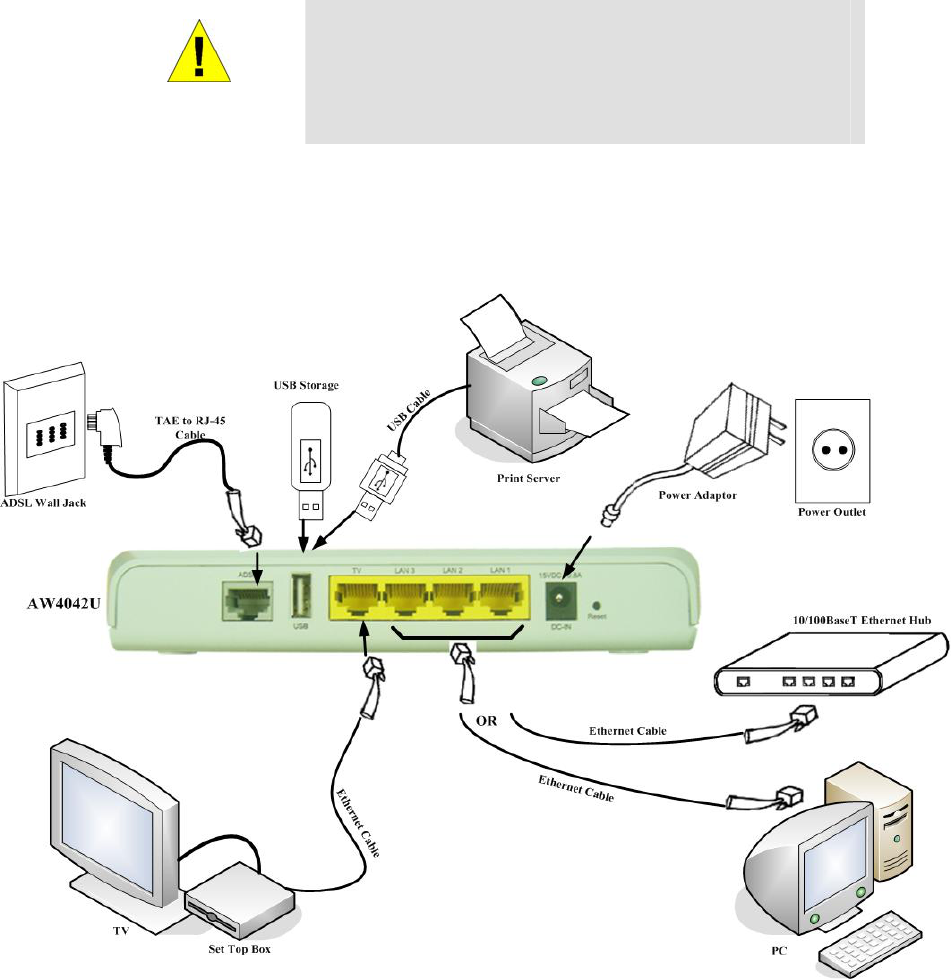
Connecting the Hardware
WARNING
Before you begin, turn the power off for all devices.
These include your computer(s), your LAN hub/switch (if
applicable), and the AW4042U.
The layout of the ports on your device may vary from the layout shown. Refer to the steps that follow for
specific instructions.
Figure 1.3. Overview of Hardware Connections
2. Login to AW4042U through web browser
I. Configure your PC IP address as 192.168.1.x within the same subnet as AW4042U (AW4042U default IP is 192.168.1.1)
and subnet mask (default is 255.255.255.0).
II. Connect AW4042U with PC through an Ethernet cable.
a. Turn on the power of AW4042U to establish ADSL link.
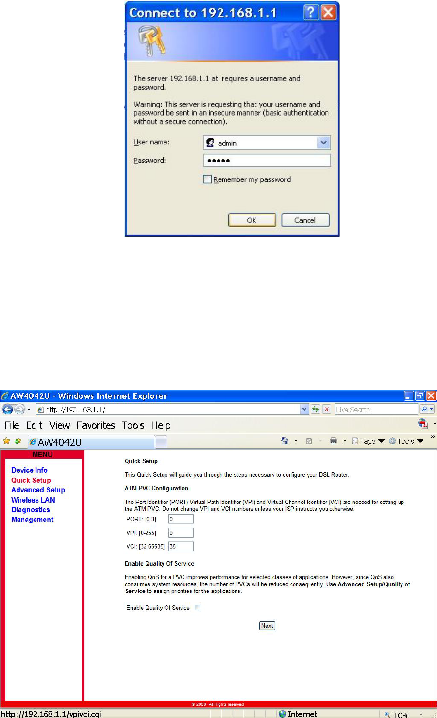
b. Enter the IP address (default is 192.168.1.1) of AW4042U from Web Browser. Login Dialog Box will pop up
as following:
- 4 -
Fig. 2.1 Login Dialog Box
c. Enter the management Username/Password and click the OK button (The default Username/Password is
admin/admin).
d. The first page will show the first page of Quick Setup. Follow the instructions to configure the AW4042U.
3. Quick Setup
I. Set up ATM PVC and QoS
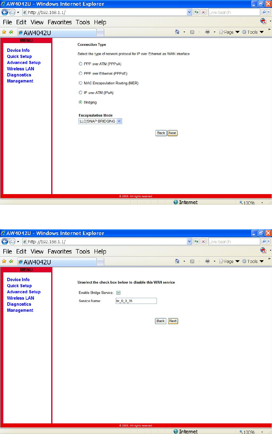
II. Configure WAN Interface
- 5 -
III. Enable/Disable Bridging Service
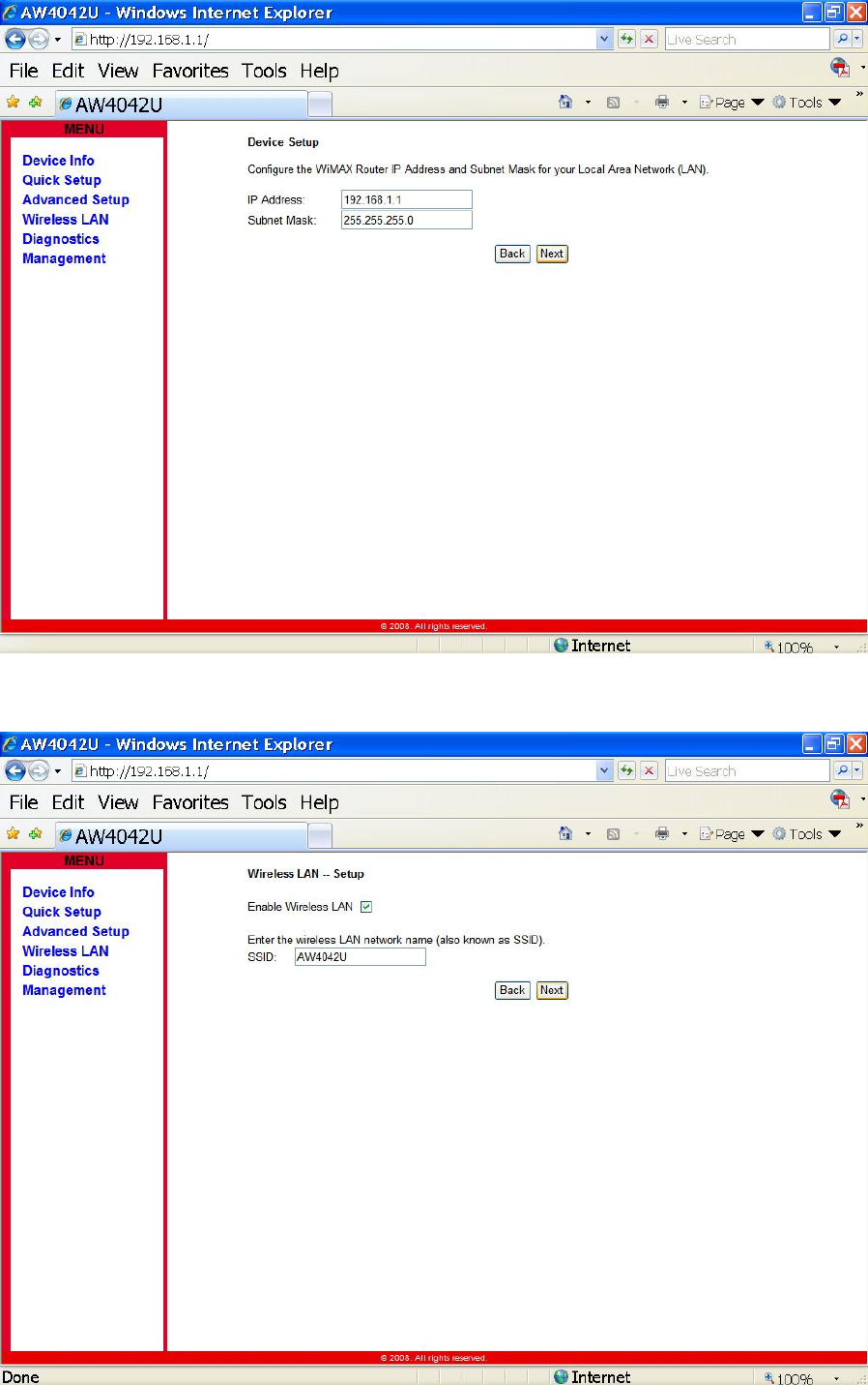
IV. Configure LAN IP Address and Subnet Mask
- 6 -
V. Setup the Wireless LAN
- 7 -
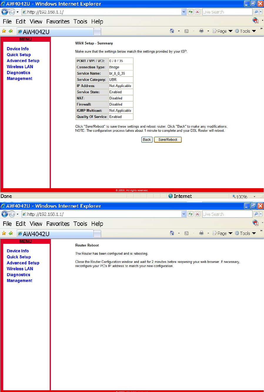
VI. Save & Reboot
- 8 -
5. USB
To connect USB devices, the IAD provides an USB 2.0 port.
I. Print Server
AW4042U includes a print server that allows connecting one printer via USB. All PCs of the IAD have access to
these printers.
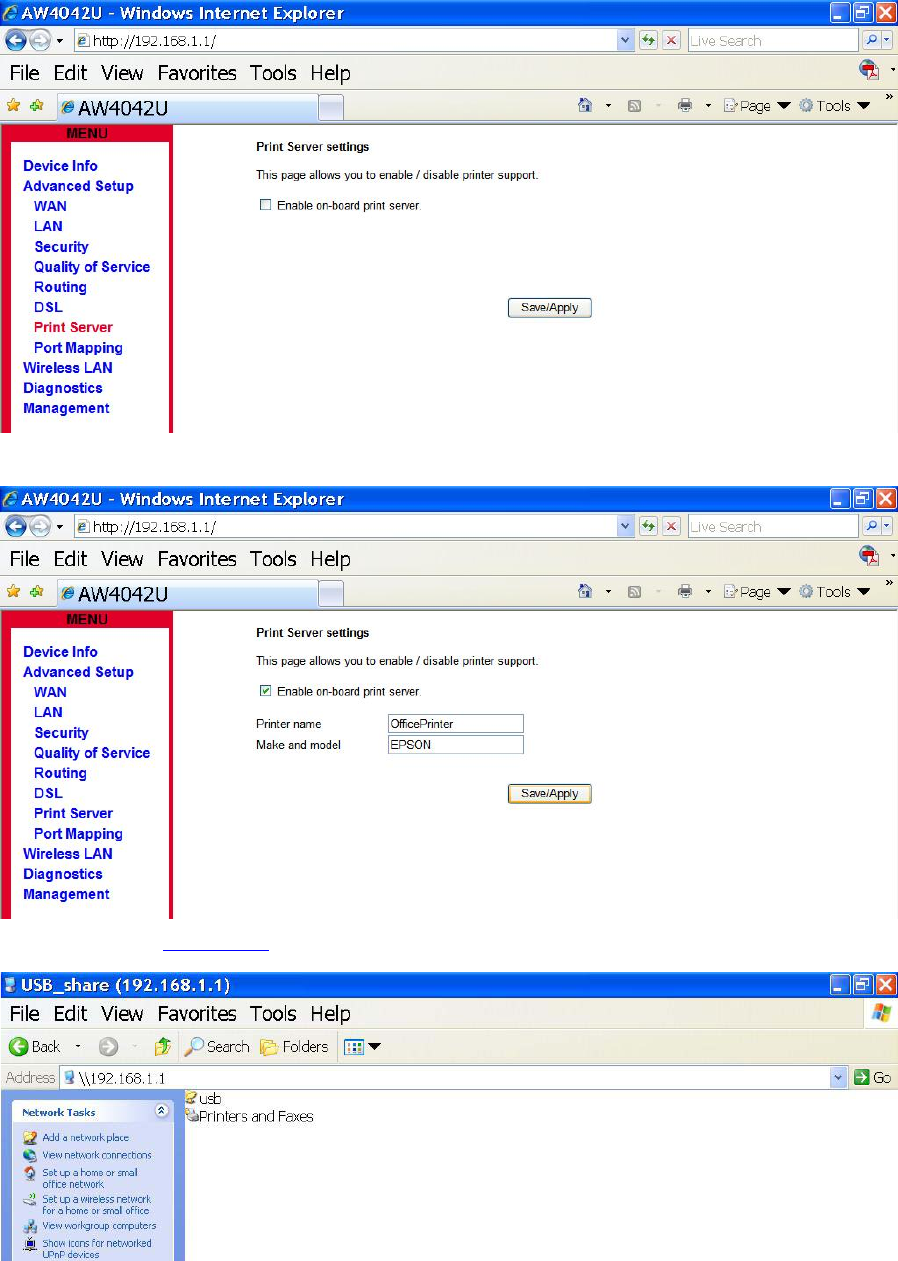
a. Go to Advanced Setup – Print Server to Enable Print Server Service
b. Enter the Printer Name then Click Save/Apply
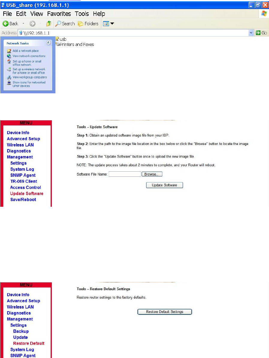
c. Enter \\192.168.1.1 in the Web Browser and Locate the Network Printer in the Network.
- 9 -
II. Network Storage
AW4042U provides a file server utility, allowing you to manage (read/write/delete) files on a Network Attached
Storage (NAS, i.e. hard disc or memory stick). AW4042U supports external hard discs up to a maximum of
5V/500mA which is 2.5W. When a hard disc needs more power, then this hard disc needs an own power supply.
AW4042U does support FAT32, NTFS and Linux/Unix (EXT2 / 3) file system.
a. Connect the USB Hard Disk or Memory Stick to the USB Port
b. Enter \\192.168.1.1 in the Web Browser and Locate the USB Drive.
5. Update Software and Restore default settings
I. Update Software
Fig. 5.1 Management – Update Software
Click “Management->Update Software” on the left frame. Locate the location of the software image, or
select the file by browsing the file system. Click ‘Update Software’ button and the system will reboot after
update complete.
II. Restore Default
Click “Management-> Settings->Restore Settings” on the left frame. Click ‘Restore Default Settings’ button
to reset AW4042U to the factory defaults.
Fig. 7.2 Tools – Restore Default Settings
- 10 -
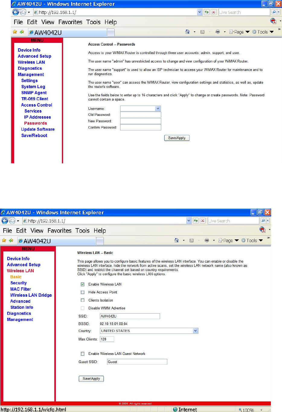
6. Change Password
Click “Management-> Access Control->Passwords”, input the data and click “Save/ Apply”
Fig. 6.1 Access Control--Passwords
9. Wireless
Click “Wireless”, input the data and click “Save/ Apply” as Figure 9.1 Wireless -- Basic
.
Figure 9.1 Wireless – Basic
- 11 -
Federal Communication Commission Interference Statement
This equipment has been tested and found to comply with the limits for a Class B digital device,
pursuant to Part 15 of the FCC Rules. These limits are designed to provide reasonable
protection against harmful interference in a residential installation. This equipment generates,
uses and can radiate radio frequency energy and, if not installed and used in accordance with
the instructions, may cause harmful interference to radio communications. However, there is
no guarantee that interference will not occur in a particular installation. If this equipment does
cause harmful interference to radio or television reception, which can be determined by turning
the equipment off and on, the user is encouraged to try to correct the interference by one of the
following measures:
- Reorient or relocate the receiving antenna.
- Increase the separation between the equipment and receiver.
- Connect the equipment into an outlet on a circuit different from that to which the receiver
is connected.
- Consult the dealer or an experienced radio/TV technician for help.
-
This device complies with Part 15 of the FCC Rules. Operation is subject to the following two
conditions: (1) This device may not cause harmful interference, and (2) this device must accept
any interference received, including interference that may cause undesired operation.
FCC Caution: Any changes or modifications not expressly approved by the party responsible for
compliance could void the user's authority to operate this equipment.
IEEE 802.11b or 802.11g operation of this product in the U.S.A. is firmware-limited to channels 1
through 11.
IMPORTANT NOTE:
FCC Radiation Exposure Statement:
This equipment complies with FCC radiation exposure limits set forth for an uncontrolled
environment. This equipment should be installed and operated with minimum distance 20cm
between the radiator & your body.
This transmitter must not be co-located or operating in conjunction with any other antenna or
transmitter.
The availability of some specific channels and/or operational frequency bands are country
dependent and are firmware programmed at the factory to match the intended destination. The
firmware setting is not accessible by the end user.