User Manual
‐1‐
WiFi Chime
C-1030
User Manual
Version: 2.0
TECOM CO., LTD.

‐2‐
Ver.2.0
Safety Precautions
Please follow these safety precautions to prevent injury or damage to property that
may be caused by fire or electrical damage.
DOs:
1.) Use the type of power recommended as seen on the label of your device.
2.) Use the power adapter in the product package.
3.) Pay attention to the power load of the outlet or prolonged lines. An overburdened
power outlet, damaged lines or plugs may cause electric shock or even fire.
Check your power cords regularly to ensure their safe functioning. If you find any
damage line or parts, please repair or replace them immediately.
4.) Leave space around your device to allow heat dissipation. This is necessary to
avoid damage caused by the overheating of the device. The long and thin holes
on the device are designed for heat dissipation to ensure that the device
continues normal functioning. Do not cover these heat dissipation holes.
DON’Ts:
1.) Do not keep this device close to a heat source or in a high temperature
environment. Keep the device away from direct sunlight.
2.) Do not keep this device in a damp or moist place. Do not spill any fluids on this
device.
3.) Do not connect this device to a PC or other electronic product unless instructed
by our customer service engineers or your internet service provider. Bad
connections may cause a power surge or fire risk.
4.)
Do not place this device on an unstable surface or support.

‐3‐
Ver.2.0
2Northern America FCC Statement
This equipment generates uses and can radiate radio frequency energy and, if not installed
and used in accordance with the instructions in this manual, may cause interference to radio
communications.
This equipment as been tested and found to comply with the limits for a Class B computing
device pursuant to Subpart J of Part 15 of FCC rules, which are designed to provide
reasonable protection against radio interference when operated in a commercial
environment. Operation of this equipment in a residential area is likely to cause interference,
in which case the user, at his or her own expense, will be required to take whatever
measures are necessary to correct the interface.
Europe CE Declaration of Conformity
This equipment complies with the requirements relating to electromagnetic compatibility,
EN55032 Class B for ITE and EN 50082‐1. This meets the essential protection requirements
of the European Council Directive 2014/53/EEC on the approximation of the laws of the
Member States relating to electromagnetic compatibility.
Japan VCCI Declaration of Conformity
This equipment complies with the Class B standard of the Voluntary Control Council for
Interference from Information Technology Equipment (VCCI). This meets the essential
protection requirements of Japan laws relating to electromagnetic compatibility.
Copyright Notice
©Copyright, 2010. All rights reserved. No part of this publication may be reproduced,
transmitted, transcribed, stored in retrieval system or translated in to any language or
computer language, in any from or by any means, electronic, mechanical, magnetic, optical,
chemical, manual or otherwise, without the prior written permission of Owner (The Company).
The Company reserves the right to revise the publication and make changes from time to time
in the contents hereof without obligation of this company to notify person of such revision or
changes. The material contained herein is supplied without representation or warranty of any
kind. The Company therefore assumes no responsibility and shall have no liability of any kind
arising from the supply or use of this document or the material contained herein.
Trademarks
Windows 98/2000/XP/NT™, NetMeeting™, Internet Explorer™ are registered trademarks of
Microsoft Corporation. All company, brand and product names are trademarks or registered
trademarks of their respective owners.

‐4‐
Ver.2.0
Revision History
Version Date Update Log Author
2.0 2015‐02‐04 2nd version for C-1030 User
Manual.
Sony

‐5‐
Ver.2.0
C-1030, networking standard compliant Wireless adapter, provides the best
quality data transmission for the truly high‐speed ‘connected home’
experience. It allows users to extend a local area network via existing
Wireless. Installation at home (or in a small office) is quick and easy as the
C1030 comes with plug‐and‐play technology.
C-1030 supports (802.11n 1x1) operation based on WSC-N101 module and
can be used with two fully programmable reception and transmission paths to
attain up to 1Gbps PHY rates co‐existence with UPA technology networks.
Key Features:
Performance
Support ITU‐T G.hn baseband plans 25, 50, 100 and 150 MHz and
MIMO techniques for powerline (based on G.9963) boosting to prevent noise
interference from other home appliances.
1 . PRODUCT OVERVIEW
‐6‐
Ver.2.0
3. C-1030 Web Configuration
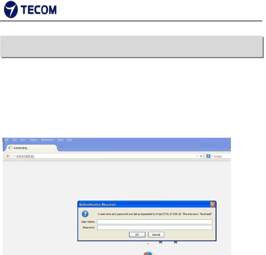
3.1. Login Page
Figure3.1‐1 shows the login window. Here, the login information should be
filled in as shown below:
Figure 3.1‐1
The default IP address of the C-1030 Wireless is 10.10.10.254
Username: admin
Password: admin
After login we can see Quick Setup page
‐7‐
Ver.2.0
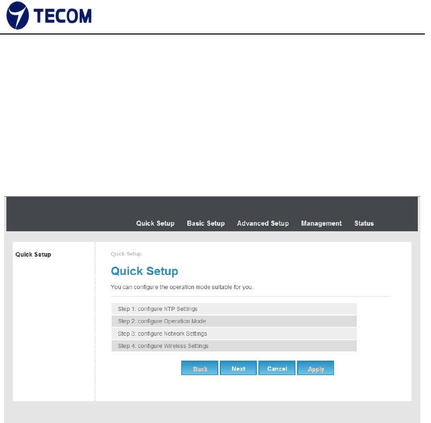
3.2. Quick Setup
Figure3.2‐1 displays the Quick setup page of the device.
Figure 3.2‐1
Using quick setup we can configure below list.
• NTP settings
• Operation Mode
• Network Settings
• Wireless Settings
‐8‐
Ver.2.0
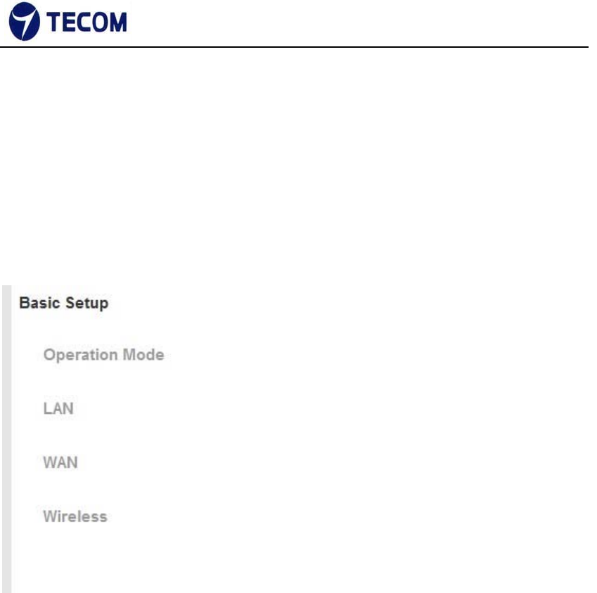
3.3. Basic Setup
Figure3.3‐1 shows basic setup of the device
Figure 3.3‐1
‐9‐
Ver.2.0
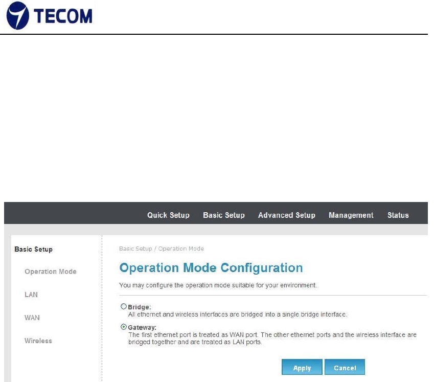
3.3.1. Operation Mode
Figure3.3.1‐1 displays operation mode settings
Figure 3.3.1‐1
In this page we can set bridge mode or gateway mode
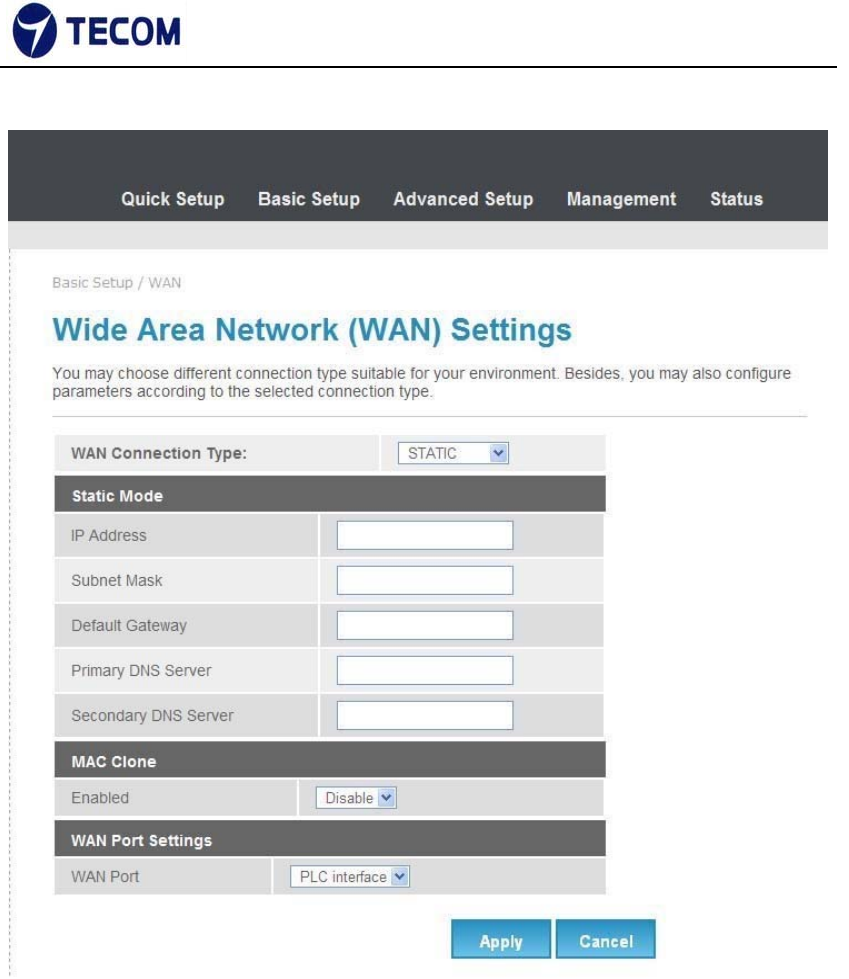
3.3.2. WAN
Figure3.3.3‐1, Figure3.3.3‐2, Figure3.3.3‐3 and Figure3.3.3‐4 displays WAN
settings information
WAN has static, DHCP, PPPoE and 3G connection types.
Configure static connection type as below
‐10‐
Ver.2.0
Figure3.3.3‐1
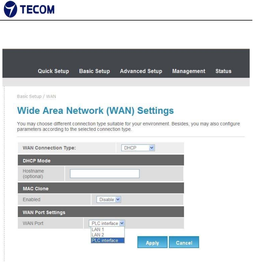
Configure DHCP connection type as below
‐11‐
Ver.2.0
Figure3.3.3‐2
‐12‐
Ver.2.0
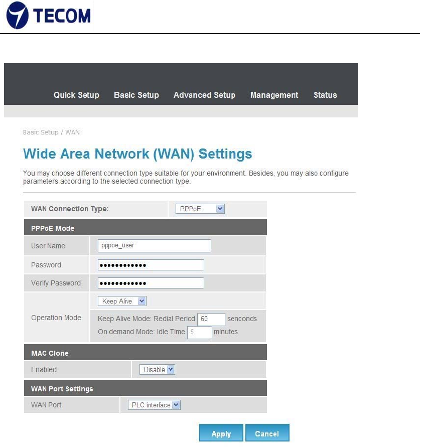
Figure3.3.3‐3
PPPoE
Select this option if your ISP requires you to use a PPPoE connection. This
option is typically used for DSL services. Select Dynamic PPPoE to obtain an
IP address automatically for your PPPoE connection. Select Static PPPoE to
use a static IP address for your PPPoE connection. Please enter the
information accordingly.
Username: Enter your username for your PPPoE
connection. Password: Enter your password for your
PPPoE connection
Operation Mode: For PPPoE connection, you can select Always on or
Connect on‐demand. Connect on demand is dependent on the traffic. If there
is no traffic (or Idle) for a pre‐specified period of time), the connection will tear
‐13‐
Ver.2.0
down automatically. And once there is traffic send or receive, the connection
will be automatically on.
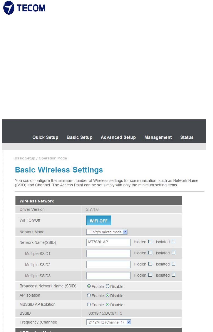
3.3.3. Wireless
Figure3.3.4‐1 and Figure3.3.4‐2 displays basic wireless information
The following page is Wireless LAN settings. Please select and input the
correct information in the following item to set Wireless function.
Figure 3.3.4‐1
‐14‐
Ver.2.0
Figure 3.3.4‐2
We can configure below settings using basic wireless settings page
SSID:
The SSID is a unique name to identify the DSL Router in the wireless LAN.
Wireless clients associating to the DSL Router must have the same SSID.
Broadcast SSID:
Select No to hide the SSID such that a station can not obtain the SSID through
passive scanning. Select yes to make the SSID visible so a station can obtain
the SSID through passive scanning.
Channel ID the range of radio frequencies used by IEEE 802.11b/g wireless
devices is called a channel
‐15‐
Ver.2.0
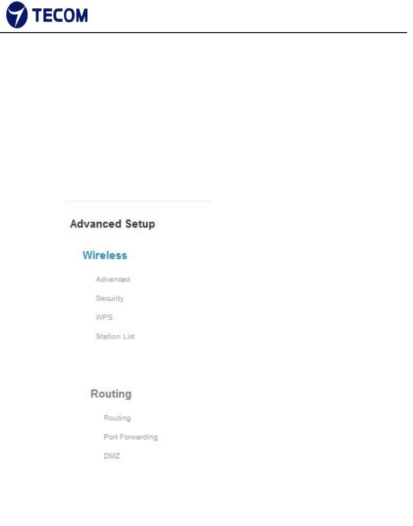
3.4. Advanced Setup
Figure3.4‐1 shows Advanced Setup menu list
Figure 3.4‐1
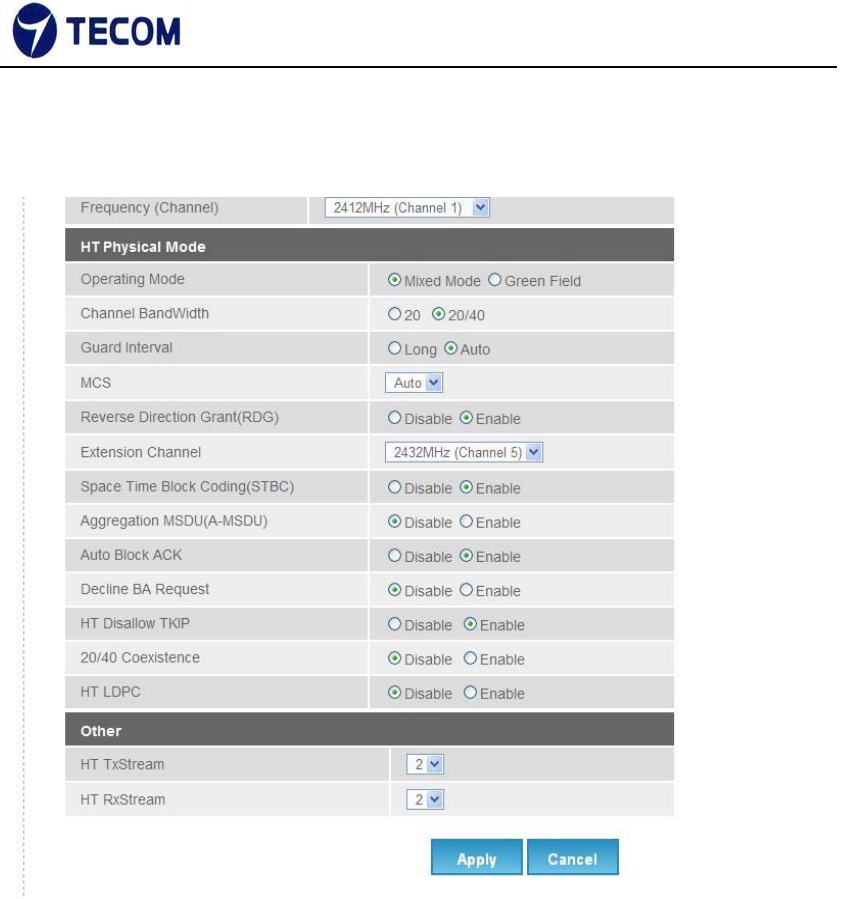
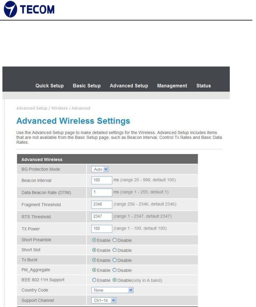
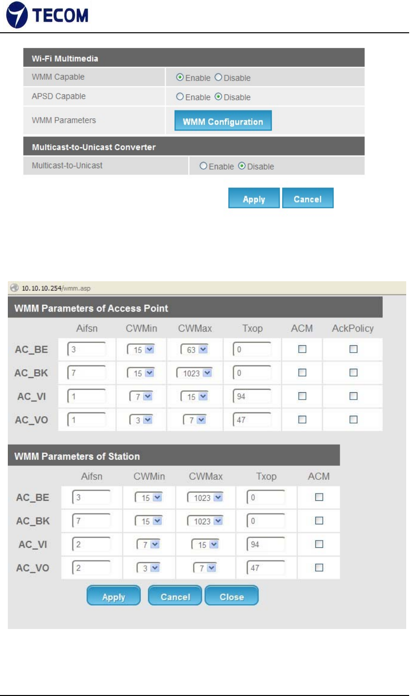
3.4.1. Advanced Wireless
Figure3.4.1‐1, Figure3.4.1‐2, Figure3.4.1‐3 shows Advanced Wireless
settings and Wi‐Fi multimedia
‐16‐
Ver.2.0
The following page is Advanced Wireless settings. Please select and input the
correct information in the following item to set Wireless functions.
Figure 3.4.1‐1
‐17‐
Ver.2.0
Figure 3.4.1‐2
Figure 3.4.1‐3

‐18‐
Ver.2.0
Beacon Interval
The Beacon Interval value indicates the frequency interval of the beacon.
Enter a value between 20 and 1000. A beacon is a packet broadcast by the
Router to synchronize the wireless network.
DTIM
This value, between 1 and 255, indicates the interval of the Delivery Traffic
Indication Message (DTIM).
RTS Threshold
The RTS (Request to Send) threshold (number of bytes) for enabling RTS
handshake Data with its frame size larger than this value will perform the RTS
handshake, setting this attribute to be larger than the maximum MSDU (MAC
service data unit) size turns off the RTS handshake, setting this attribute to
zero turns on the RTS handshake. Enter a value between 0 and 2432.
Fragmentation Threshold
The threshold (number of bytes) for the fragmentation boundary for directed
messages. It is the maximum data fragment size that can be sent. Enter a
value between 256 and 2432.
‐19‐
Ver.2.0
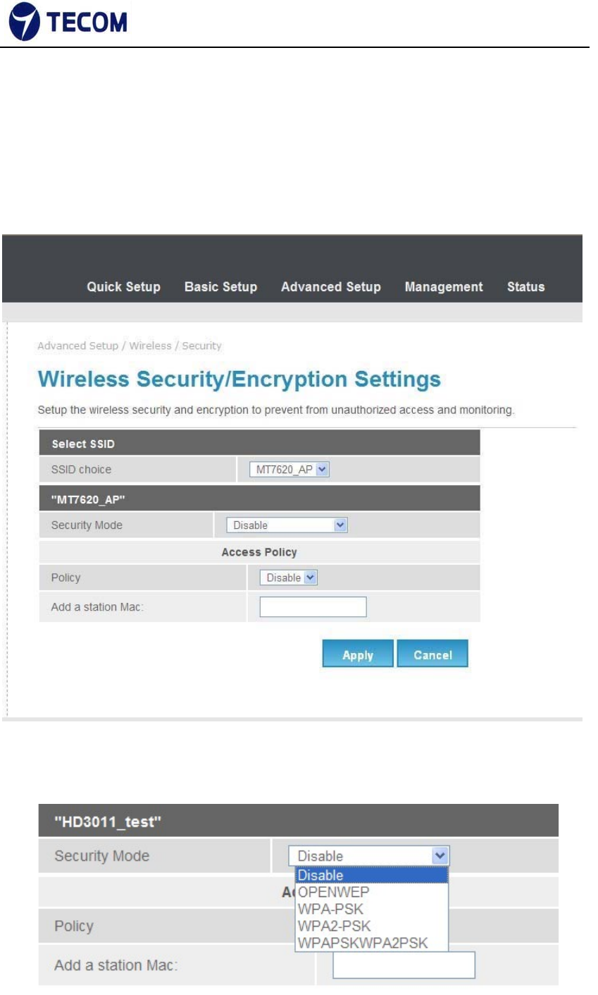
3.4.2. Security
Figure3.4.2‐1, Figure3.4.2‐2, Figure3.4.2‐3, and Figure3.4.2‐4 shows wireless
Security information
Figure 3.4.2‐1
‐20‐
Ver.2.0
Figure 3.4.2‐2
Figure 3.4.2‐3
Figure 3.4.2‐4
Using this page we can set SSID choice, Security mode, Access Policy and
WPA.

‐21‐
Ver.2.0
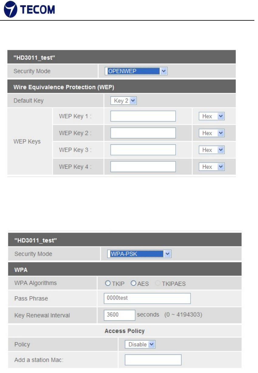
Security Mode
OPEN WEP
WEP (Wired Equivalent Privacy) encrypts data frames before transmitting
over the wireless network. Select Disable to allow all wireless computers to
communicate with the access points without any data encryption. Select 64‐
bit
WEP or 128‐bit WEP to use data encryption.
Key#1~Key#4 The WEP keys are used to encrypt data. Both the DSL Router
and the wireless clients must use the same WEP key for data transmission. If
you chose 64‐bit WEP, then enter any 10 hexadecimal digits ("0‐9", "A‐F")
preceded by 0x for each key (1‐4). If you chose 128‐bit WEP, then enter 26
hexadecimal digits ("0‐9", "AF") preceded by 0x for each key (1‐4).The values
must be set up exactly the same on the Access Points as they are on the
wireless client stations. The same value must be assigned to Key 1 on both
the access point (your DSL Router) and the client adapters, the same value
must be assigned to Key 2 on both the access point and the client stations
and so on, for all four WEP keys.
WPA‐PSK
Wi‐Fi Protected Access, pre‐shared key. Encrypts data frames before
transmitting over the wireless network.
Pre‐shared Key: the Pre‐shared Key is used to encrypt data. Both the DSL
Router and the wireless clients must use the same WPA‐PSK key for data
transmission.
WPA2‐PSK
Short for Wi‐Fi Protected Access 2 ‐ Pre‐Shared Key, and also called WPA
or WPA2 Personal, it is a method of securing your network using WPA2

‐22‐
Ver.2.0
with the use of the optional Pre‐Shared Key (PSK) authentication, which
was designed for home users without an enterprise authentication server.
To encrypt a network with WPA2‐PSK you provide your router not with an
encryption key, but rather with a plain‐English passphrase between 8 and 63
characters long.
Using a technology called TKIP (for Temporal Key Integrity Protocol), that
passphrase, along with the network SSID, is used to generate unique
encryption keys for each wireless client. And those encryption keys are
constantly changed. Although WEP
also supports passphrases, it does so only as a way to more easily create
static keys, which are usually comprised of the hex characters 0‐9 and A‐F.
WPA Algorithms
TKIP
TKIP stands for “Temporal Key Integrity Protocol.” It was a stopgap encryption
protocol introduced with WPA to replace the very‐insecure WEP encryption at
the time. TKIP is actually quite similar to WEP encryption.
AES
AES stands for “Advanced Encryption Standard.” This was a more secure
encryption protocol introduced with WPA2, which replaced the interim WPA
standard.
TKIPAES
When you set your router to use WPA2, you usually have the option to use
AES, or TKIP+AES. When your device is set to "WPA2 with TKIP+AES" it
means that network devices that can use WPA2 will connect with WPA2, and
network devices that can only use WPA will connect with WPA.
‐23‐
Ver.2.0
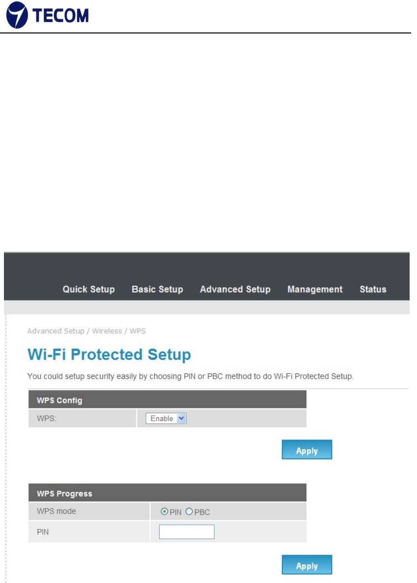
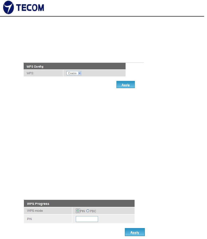
3.4.3. WPS
Figure3.4.3‐1, Figure3.4.3‐2 shows WPS settings
Wi‐Fi Protected Setup (WPS; originally Wi‐Fi Simple Configuration) is a
network security standard that attempts to allow users to easily secure a
wireless home network but could fall to brute‐force attacks if one or more of
the network's access points do not guard against the attack.
Figure 3.4.3‐1
‐24‐
Ver.2.0
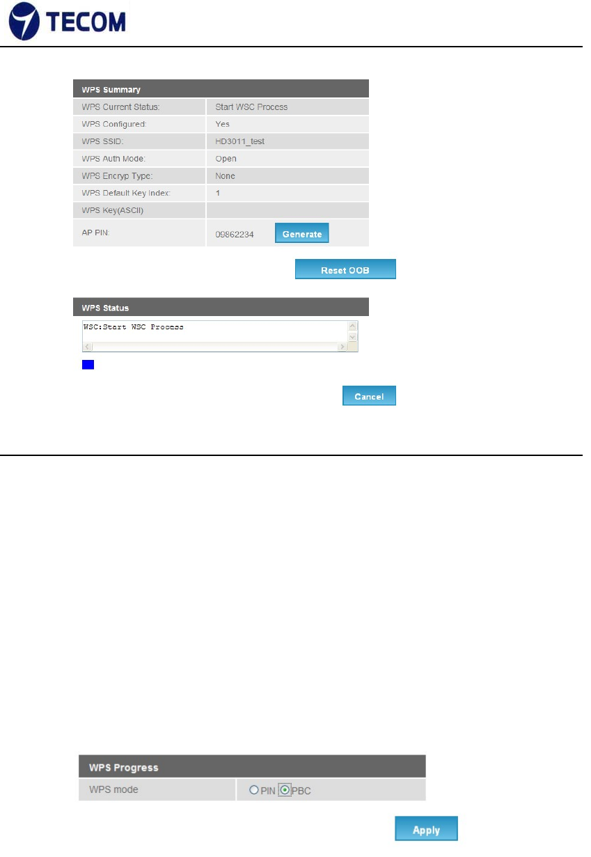
Figure 3.4.3‐2
WPS Settings
There two WPS mode, one is PIN code and other one is PBC.
PIN method in which a personal identification number (PIN) has to be
read from
either a sticker or display on the new wireless device. This PIN must then be
entered at the "representant" of the network, usually the network's access
point. Alternately, a PIN provided by the access point may be entered into the
new device. This method is the mandatory baseline mode and every
WPScertified product must support it.
Push button method
in which the user has to push a button, either an actual or virtual one, on
both the access point and the new wireless client device. Support of this
mode is mandatory for access points and optional for connecting devices.
‐25‐
Ver.2.0
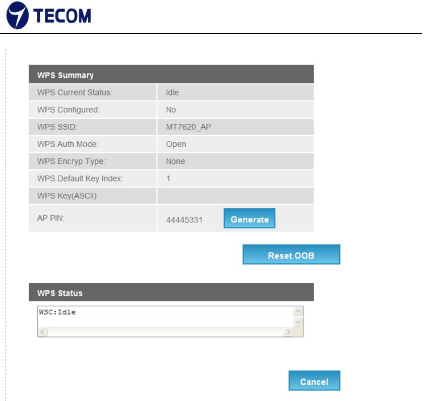
Example of configuration
1. Make sure WPS is enabled on system wise.
2. For Pin method
1). Select radio button PIN method.
2). Enable your Wi‐Fi client (Notebook, Mobile, PAD…etc). And check
WPS. 3). Take PIN at client and specify same one in your AP device.
4). Click “Apply“below “WPS Progress” table to trigger WPS
session. 5). Once connected, “WPS current status” will be put
“Connected”.
‐26‐
Ver.2.0
3. For PBC at Web
1). Select the following radio button, and click “Apply” Button to trigger WPS
session.
2). at Wi‐Fi client side, select PBC method. Within 2 minutes, they are
automatically connected.
3). Once connected, “WPS current status” will be put “Connected”.
4. For physical PBC on the housing:
1). Special Note: WPS is enabled on system wise.
‐27‐
Ver.2.0
2). At wifi client side, select PBC method.
3). Within 2 minutes, please push physical PBC button at housing.
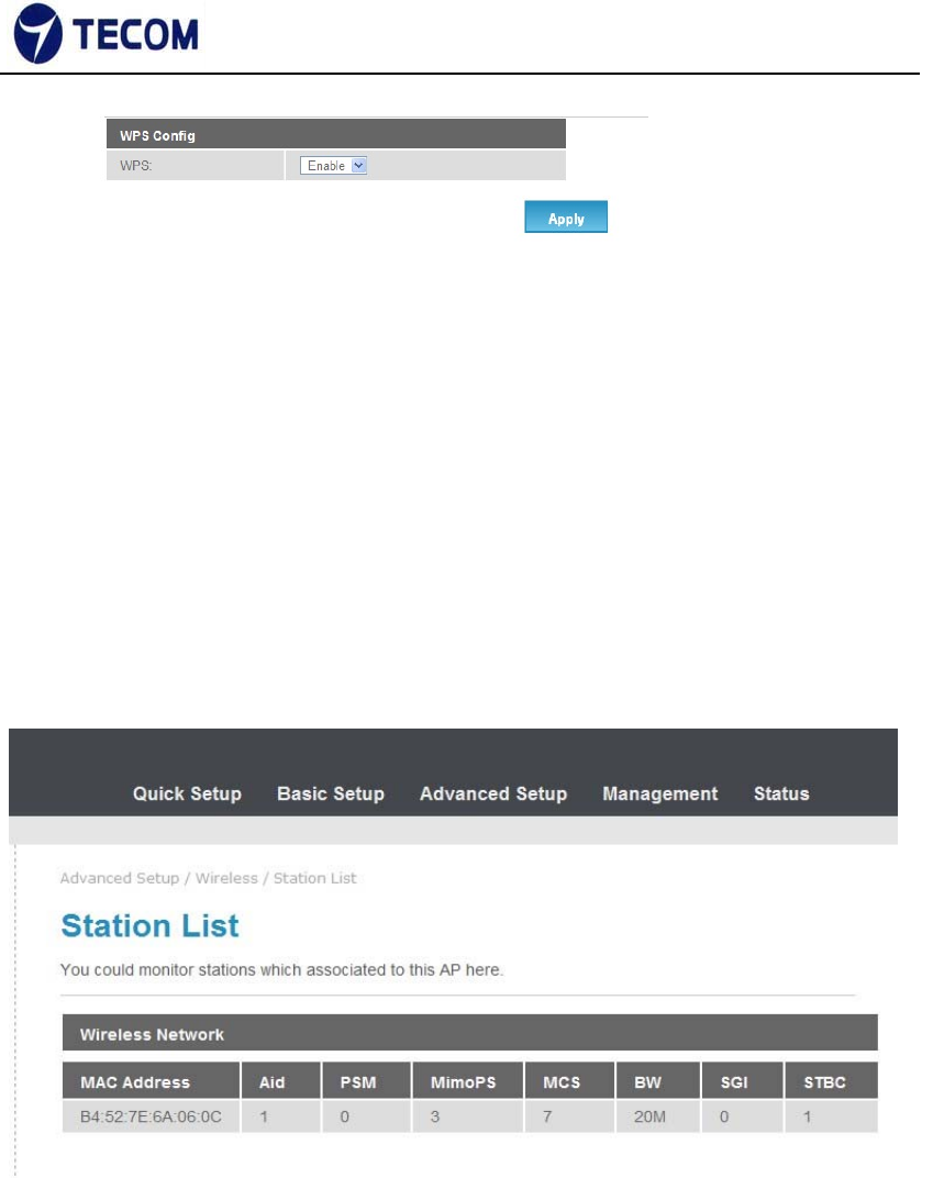
3.4.4. Station List
Figure3.4.4‐1 display the wireless network station list
Figure 3.4.4‐1
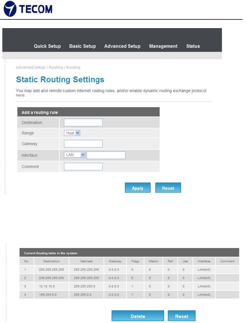
3.4.5. Routing
Figure3.4.5‐1, Figure3.4.5‐2 displays Static Routing Settings
‐28‐
Ver.2.0
Figure 3.4.5‐1
Figure 3.4.5‐2
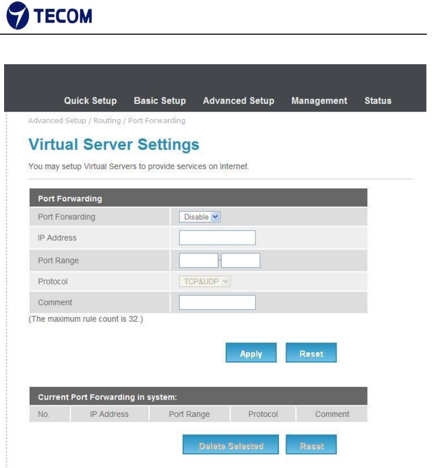
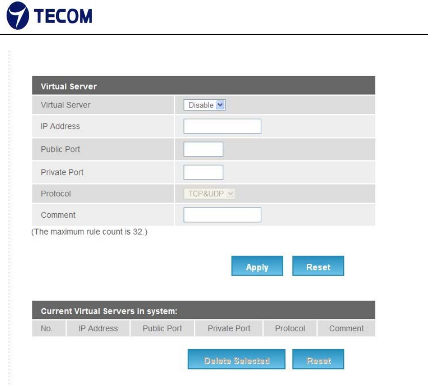
3.4.6. Port Forwarding
Figure3.4.6‐1, Figure3.4.6‐2 displays Port Forwarding setup and information
‐29‐
Ver.2.0
Figure 3.4.6‐1
‐30‐
Ver.2.0
Figure 3.4.6‐2
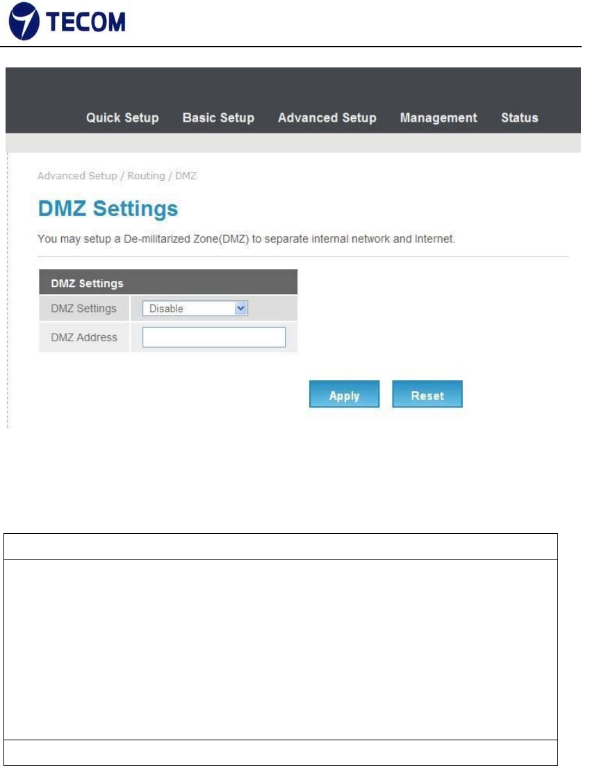
3.4.7. DMZ Settings
Figure3.4.7‐1 displays DMZ settings page
The De‐Militarized Zone (DMZ) is a network which, when compared to the LAN,
has fewer firewall restrictions, by default. This zone can be used to host servers
(such as a web server, ftp server, or email server, for example) and give public
access to them.
The eighth LAN port on the router can be dedicated as a hardware DMZ port
for safely providing services to the Internet, without compromising security on
your LAN.
‐31‐
Ver.2.0
FCC+IC USER WARNING
1.§ P15.21 Information to user.
Notice:
Anychangesormodificationsnotexpresslyapprovedbythepartyresponsiblefor
compliancecouldvoidyourauthoritytooperatetheequipment.
法文:
Aucunemodificationapportéeàl’appareilparl’utilisateur,quellequ’ensoitlanature.
Toutchangementoumodificationpeuventannulerledroitd’utilisationdel’appareil
parl’utilisateur.
2.§ P15.105 Information to the user.

‐32‐
Ver.2.0
Note:ThisequipmenthasbeentestedandfoundtocomplywiththelimitsforaClassB
digitaldevice,pursuanttopart15oftheFCCRules.Theselimitsaredesignedto
providereasonableprotectionagainstharmfulinterferenceinaresidentialinstallation.
Thisequipmentgenerates,usesandcanradiateradiofrequencyenergyand,ifnot
installedandusedinaccordancewiththeinstructions,maycauseharmfulinterference
toradiocommunications.However,thereisnoguaranteethatinterferencewillnot
occurinaparticularinstallation.Ifthisequipmentdoescauseharmfulinterferenceto
radioortelevisionreception,whichcanbedeterminedbyturningtheequipmentoff
andon,theuserisencouragedtotrytocorrecttheinterferencebyoneormoreofthe
followingmeasures:
—Reorientorrelocatethereceivingantenna.
—Increasetheseparationbetweentheequipmentandreceiver.
—Connecttheequipmentintoanoutletonacircuitdifferentfromthattowhichthe
receiverisconnected.
—Consultthedealeroranexperiencedradio/TVtechnicianforhelp.
法文:
ThisClassBdigitalapparatuscomplieswithCanadianICES‐003.
Toreducepotentialradiointerferencetootherusers,theantennatype
anditsgainshouldbesochosenthattheequivalentisotropicallyradiated
power(e.i.r.p.)isnotmorethanthatpermittedforsuccessful
communication.
ThisdevicecomplieswithIndustryCanadalicence‐exemptRSSstandard(s).
Operationissubjecttothefollowingtwoconditions:
1. Thisdevicemaynotcauseinterference,and
2. Thisdevicemustacceptanyinterference,includinginterferencethatmay
causeundesiredoperationofthedevice.
CetappareilnumériquedelaclasseBestconformeàlanormeNMB‐003
Canada.
Pourréduirelerisqued’interférenceauxautresutilisateurs,letype
d’antenneetsongaindoiventêtrechoisiesdefaçonquelapuissance
isotroperayonnéeéquivalente(PIRE)nedépassepascequiest
nécessairepourunecommunicationréussie.
CetappareilestconformeàlanormeRSSIndustrieCanadaexemptsdelicence
norme(s).Sonfonctionnementestsoumisauxdeuxconditionssuivantes:
1. Cetappareilnepeutpasprovoquerd’interférenceset
2. Cetappareildoitacceptertouteinterférence,ycomprislesinterférences
quipeuventcauserunmauvaisfonctionnementdudispositif.

‐33‐
Ver.2.0
3.§ P15.19 FCC Labelling requirement
Notice:
ThisdevicecomplieswithPart15oftheFCCRulesandIndustryCanadalicense‐exemptRSS
standard(s).Operationissubjecttothefollowingtwoconditions:(1)thisdevicemaynot
causeinterference,and(2)thisdevicemustacceptanyinterference,includinginterference
thatmaycauseundesiredoperationofthedevice.
法文:
LeprésentappareilestconformeauxCNRd'IndustrieCanadaapplicablesauxappareils
radioexemptsdelicence.L'exploitationestautoriséeauxdeuxconditionssuivantes:(1)
l'appareilnedoitpasproduiredebrouillage,et(2)l'utilisateurdel'appareildoitaccepter
toutbrouillageradioélectriquesubi,mêmesilebrouillageestsusceptibled'en
compromettrelefonctionnement.
4.FCC/IC RF Radiation Exposure Statement:
FCC
1. ThisTransmittermustnotbeco‐locatedoroperatinginconjunctionwithanyother
antennaortransmitter.
2. ThisequipmentcomplieswithFCCRFradiationexposurelimitssetforthforan
uncontrolledenvironment.This
equipmentshouldbeinstalledandoperatedwithaminimumdistanceof20centimeters
betweentheradiatorandyour
body.
法文:
1.L'émetteurnedoitpasêtrecolocalisénifonctionnerconjointementavecàautre
antenneouautreémetteur.2.Cetappareilestconformeauxlimitesd'expositionaux
rayonnementsdelaICpourunenvironnementnoncontrôlé.L'antennedoitêtreinstallé
defaçonàgarderunedistanceminimalede20centimètresentrelasourcede
rayonnementsetvotrecorps.
IC