Tecom Co EG30WV Intelligent Gatway User Manual AH4021
Tecom Co Ltd Intelligent Gatway AH4021
Tecom Co >
Contents
- 1. Users manual 1
- 2. Users manual 2
- 3. Users manual 3
Users manual 2
Administrative Guide Configuration
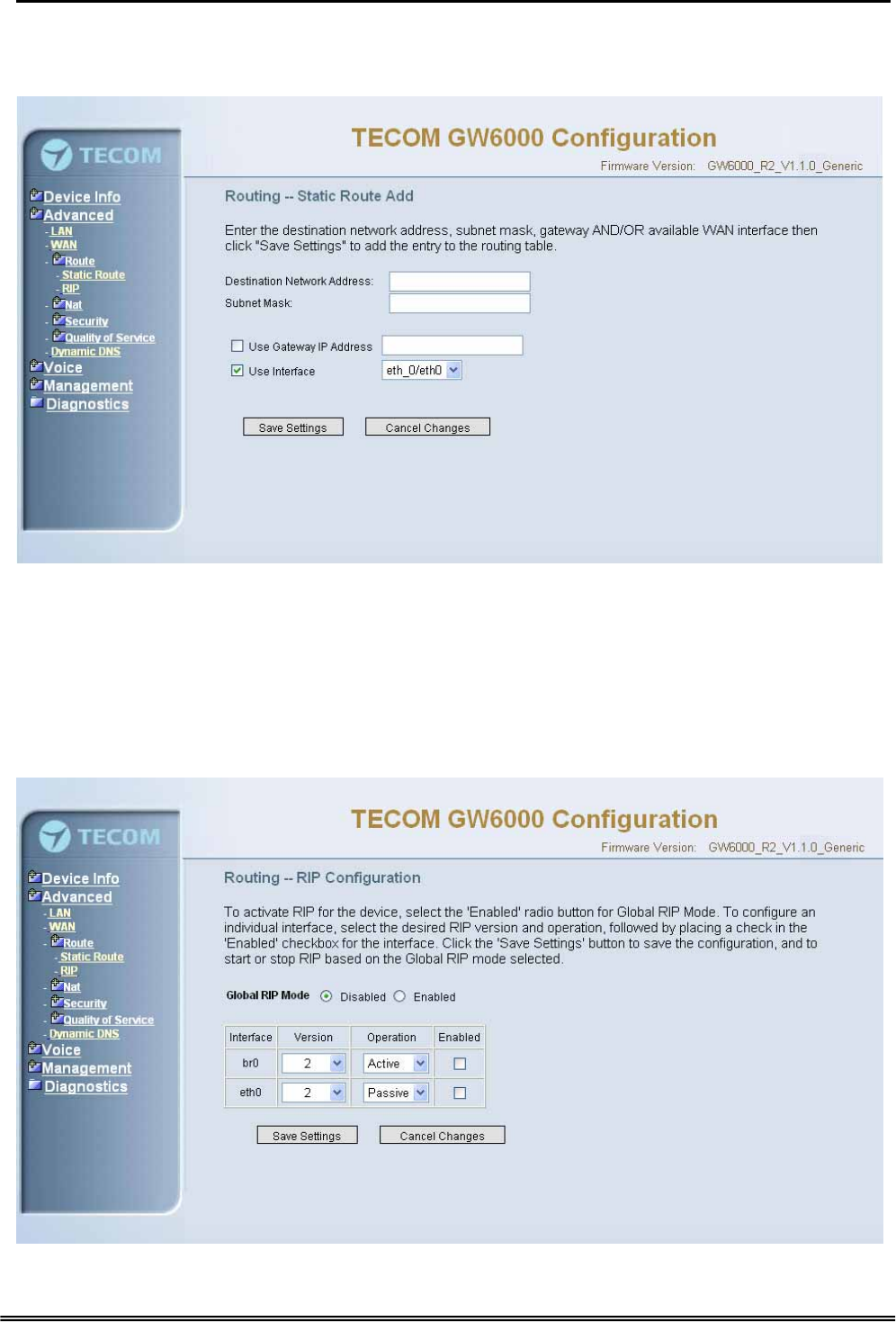
Click on Add to create a new Static Route. Enter the destination network address,
subnet mask, gateway AND/OR available WAN interface then click "Save Settings" to
add the entry to the routing table. (Figure 6-10-1, 6-10-2)
Figure 6-10-2. Advanced Setup – Route – Static Route – Add
6.4.3.2 RIP
To activate RIP for the device, select the 'Enabled' radio button for Global RIP Mode. To
configure an individual interface, select the desired RIP version and operation, followed
by placing a check in the 'Enabled' checkbox for the interface. Click the 'Apply' button to
save the configuration, and to start or stop RIP based on the Global RIP mode selected.
(Figure 6-11)
Figure 6-11. Advanced Setup – Route – RIP
Copy Right 2006 Tecom, Co. LTD. All rights reserved Page 37 of 107
Administrative Guide Configuration
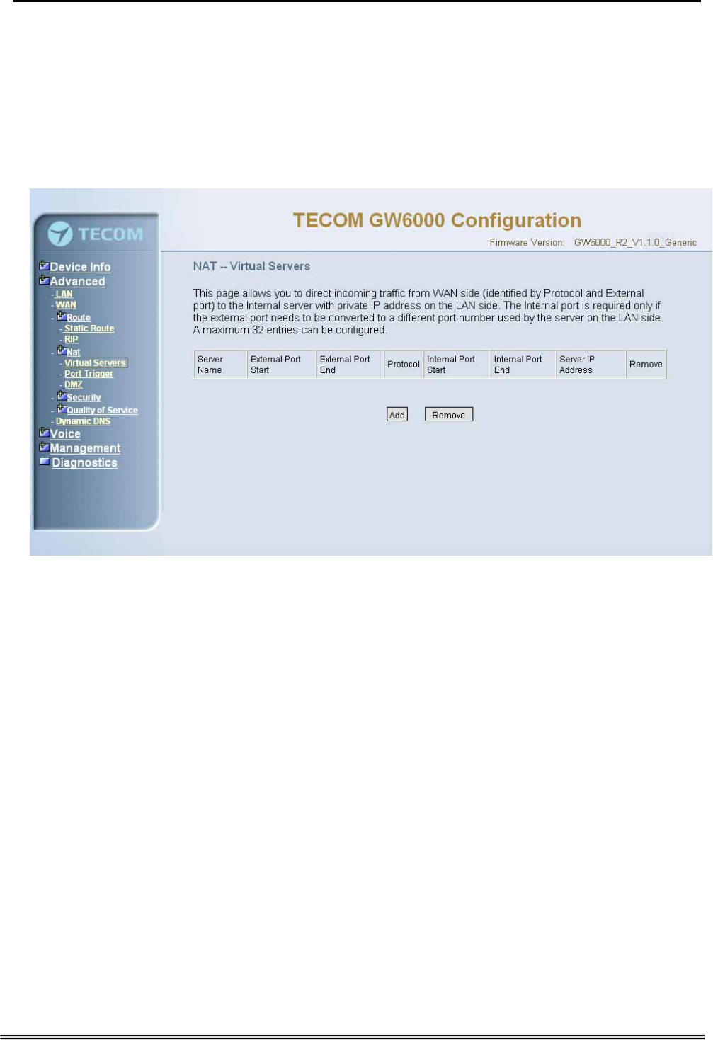
6.4.4 NAT
It’s separated into three parts: Virtual Servers, Port Trigger, and DMZ.
6.4.4.1 Virtual Servers
Virtual Server allows you to direct incoming traffic from WAN side (identified by Protocol,
IP address and service port) to the internal server with private IP address on the LAN
side. The Internal port is required only if the external port needs to be converted to a
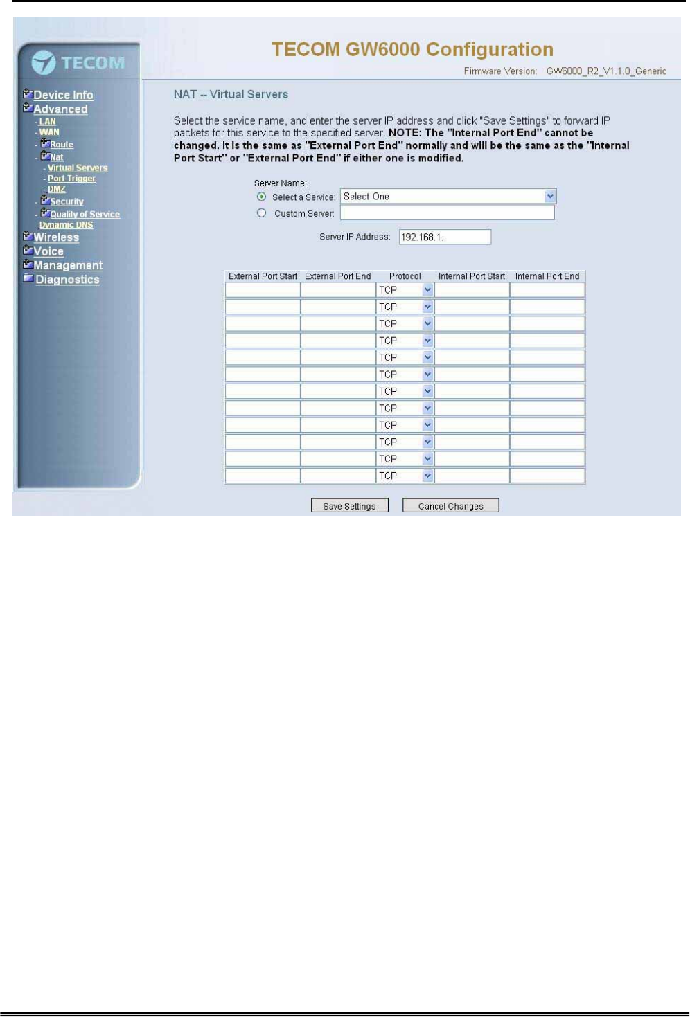
different port number used by the server on the LAN side. (Figure 6-12-1, Figure 6-12-2)
Figure 6-12-1. Advanced Setup – NAT – Virtual Servers
Copy Right 2006 Tecom, Co. LTD. All rights reserved Page 38 of 107
Administrative Guide Configuration
Figure 6-12-2. Advanced Setup – NAT – Virtual Servers – Add
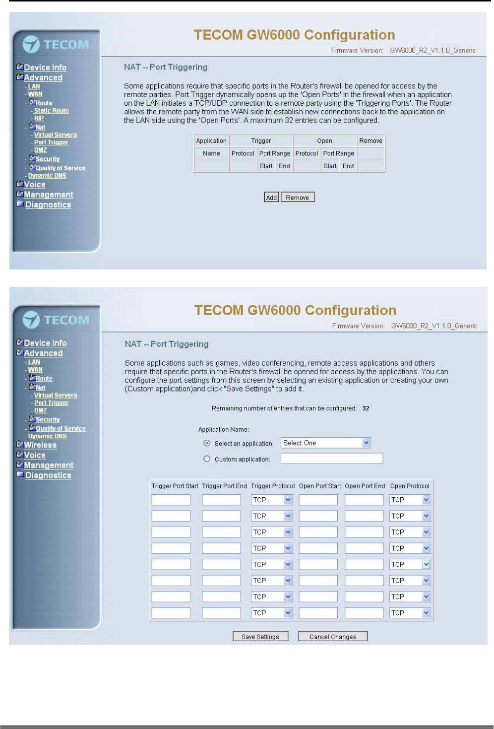
6.4.4.2 Port Triggering
Some applications require that specific port(s) in the Router's firewall be opened for
access by the remote parties. Port Trigger dynamically opens up the 'Open Ports' in the
firewall when an application on the LAN initiates a TCP/UDP connection to a remote
party using the 'Triggering Ports'. The Router allows the remote party from the WAN
side to establish new connections back to the application on the LAN side using the
'Open Ports'. (Figure 6-13-1, 6-13-2)
Copy Right 2006 Tecom, Co. LTD. All rights reserved Page 39 of 107
Administrative Guide Configuration
Figure 6-13-1. Advanced Setup – NAT – Port Triggering
Figure 6-13-2. Advanced Setup – NAT – Port Triggering – Add
Copy Right 2006 Tecom, Co. LTD. All rights reserved Page 40 of 107
Administrative Guide Configuration
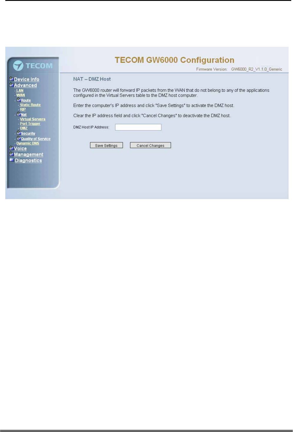
6.4.4.3 DMZ
The EUT will forward IP packets from the WAN that do not belong to any of the
applications configured in the Virtual Servers table to the DMZ host computer. (Figure 6-
14)
Figure 6-14. Advanced Setup – NAT – DMZ
6.4.5 Security
The configuration display only when WAN page’s security option is selected. It’s
separated into three parts: Incoming Filter, Output Filter, and Parental Control.
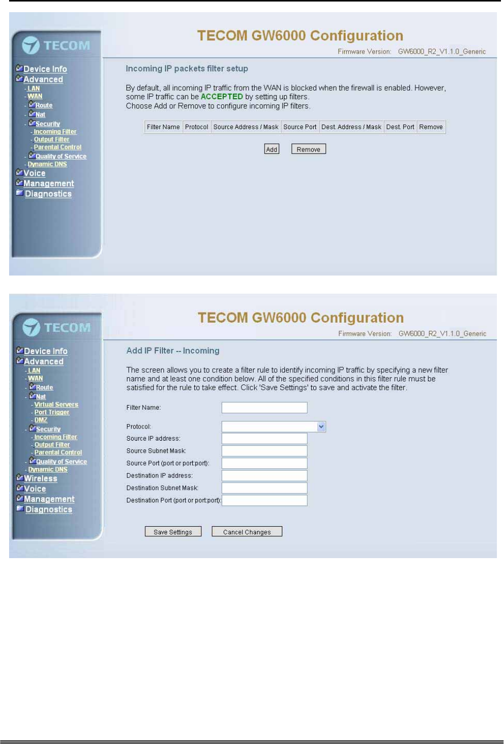
6.4.5.1 Incoming Filter
It allows the users to create a filter rule to identify incoming IP traffic by specifying a new
filter name and at least one condition. All of the specified conditions in this filter rule
must be satisfied for the rule to take effect. (Figure 6-15-1, Figure 6-15-2)
By default, all incoming IP traffic from the WAN will be blocked if it is not consistent with
the incoming filter rules. In fact, EUT has opened some necessary ports such as
web port, sip ports and rtp ports, to make sure that voice application can communicate
well.
Copy Right 2006 Tecom, Co. LTD. All rights reserved Page 41 of 107
Administrative Guide Configuration
Figure 6-15-1. Advanced Setup – Security – Incoming IP Filtering
Figure 6-15-2. Advanced Setup – Security – Incoming IP Filtering – Add
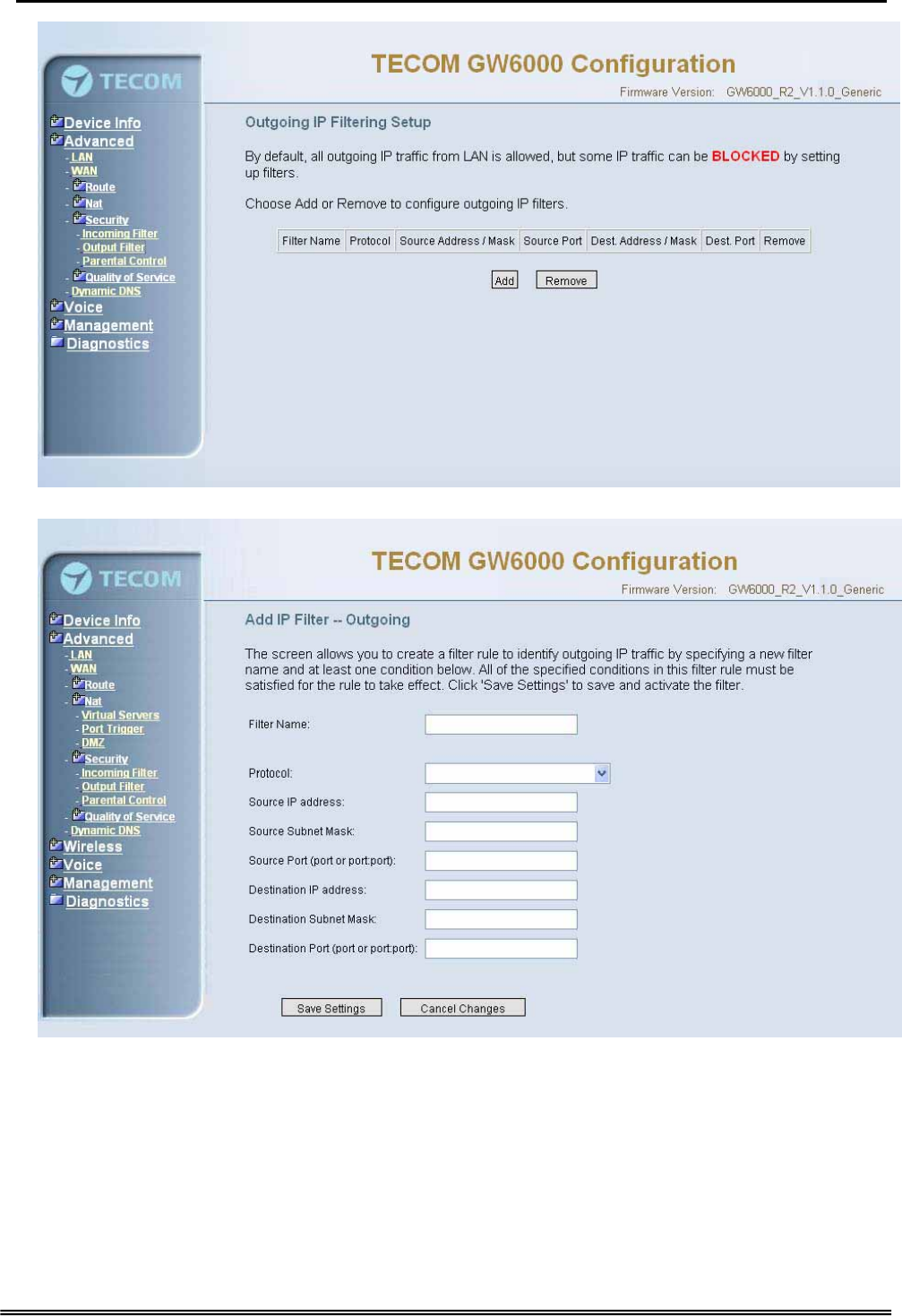
6.4.5.2 Output Filter
It allows the users to create a filter rule to identify outgoing IP traffic by specifying a new
filter name and at least one condition. All of the specified conditions in this filter rule
must be satisfied for the rule to take effect. (Figure 6-16-1, Figure 6-16-2)
Copy Right 2006 Tecom, Co. LTD. All rights reserved Page 42 of 107
Administrative Guide Configuration
Figure 6-16-1. Advanced Setup – Security – Outgoing IP Filtering
Figure 6-16-2. Advanced Setup – Security – Outgoing IP Filtering – Add
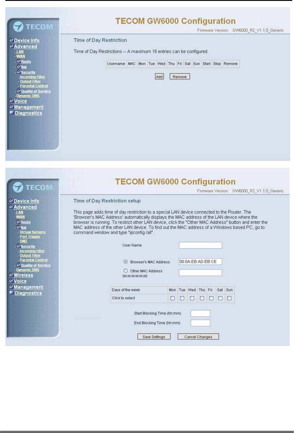
6.4.5.3 Parental Control
It adds time restriction to a special LAN device connected to the Router. The 'Browser's
MAC Address' automatically displays the MAC address of the LAN device where the
browser is running. To restrict other LAN device, click the "Other MAC Address" button
and enter the MAC address of the other LAN device. (Figure 6-17-1, Figure 6-17-2)
Copy Right 2006 Tecom, Co. LTD. All rights reserved Page 43 of 107
Administrative Guide Configuration
Figure 6-17-1. Advanced Setup – Security –Parental Control
Figure 6-17-2. Advanced Setup – Security –Parental Control – Add
6.4.6 Quality of Service
It’s separated into two parts: Traffic Class, and Bandwidth Control.
Copy Right 2006 Tecom, Co. LTD. All rights reserved Page 44 of 107
Administrative Guide Configuration
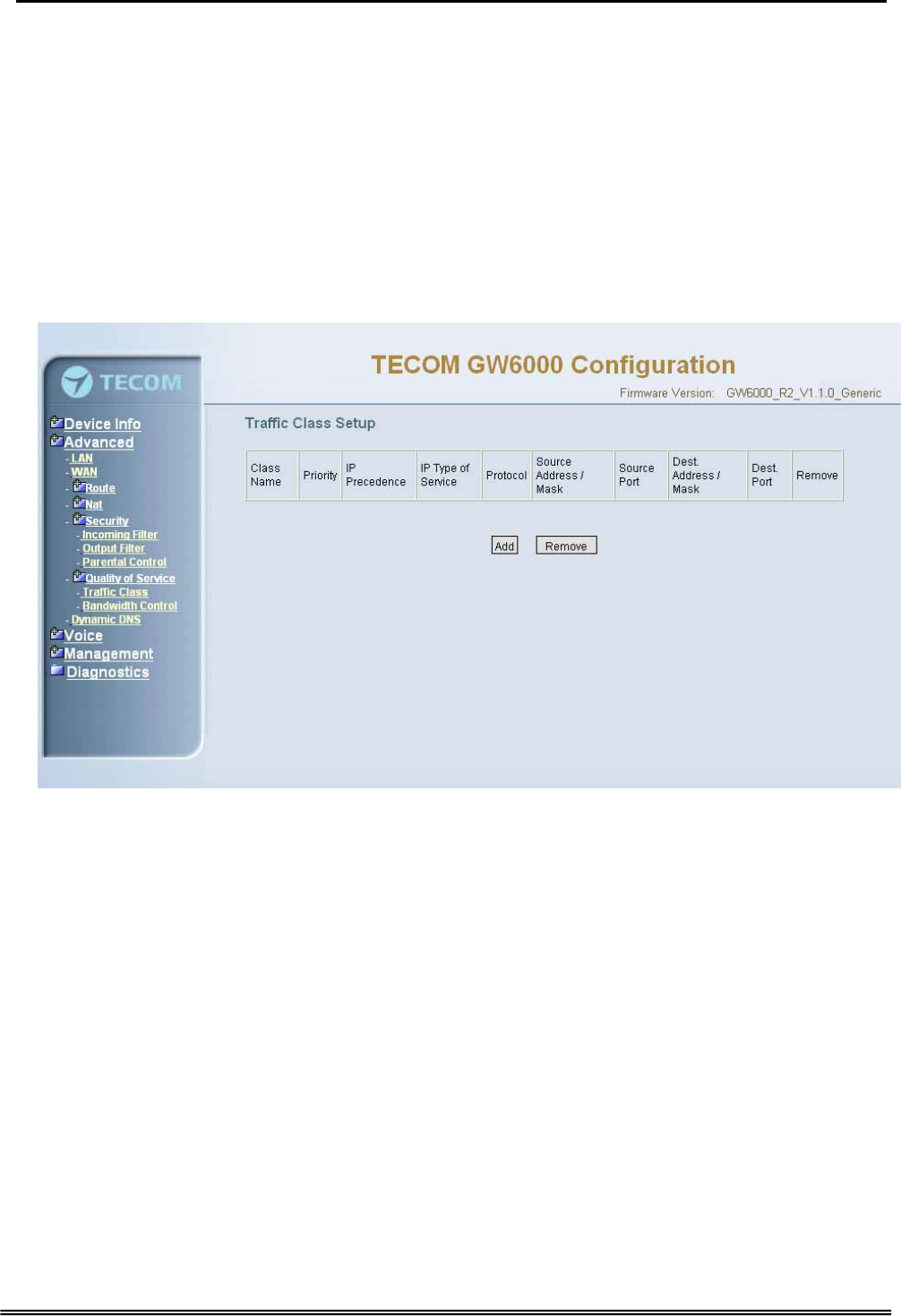
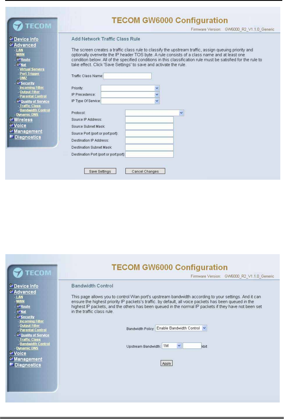
6.4.6.1 Traffic Class
Click on Add to create a class to identify the IP traffic by specifying at least one condition
below. If multiple conditions are specified, all of them should be satisfied to make sure
the rule will take effect. (Figure 6-18-1, Figure 6-18-2)
IP QoS is applied to the traffic from LAN to WAN; the traffic from WAN to LAN will not be
applied.
Enter the QoS class name for this policy. Define the priority for this policy, and the
priority will be used by the next bandwidth control setting. EUT will modify the IP
header with new IP Precedence and/or IP Type Of Service fields.
It’s a IP Layer QoS policy. At least (but not limited to) one condition must be configured.
Figure 6-18-1. Advanced Setup – Quality of Service – Traffic Class
Copy Right 2006 Tecom, Co. LTD. All rights reserved Page 45 of 107
Administrative Guide Configuration
Figure 6-18-2. Advanced Setup – Quality of Service – Traffic Class – Add
6.4.6.2 Bandwidth Control
This page allows you to control WAN port's upstream bandwidth according to your
settings (Figure 6-19). And it can ensure the highest priority IP packets' traffic firstly. By
default, all voice packets has been queued in the highest IP packets, and the others has
been queued in the normal IP packets if they have not been set in the priority field of the
traffic class rule.
Copy Right 2006 Tecom, Co. LTD. All rights reserved Page 46 of 107
Administrative Guide Configuration
Figure 6-19. Advanced Setup – Quality of Service – Bandwidth Control
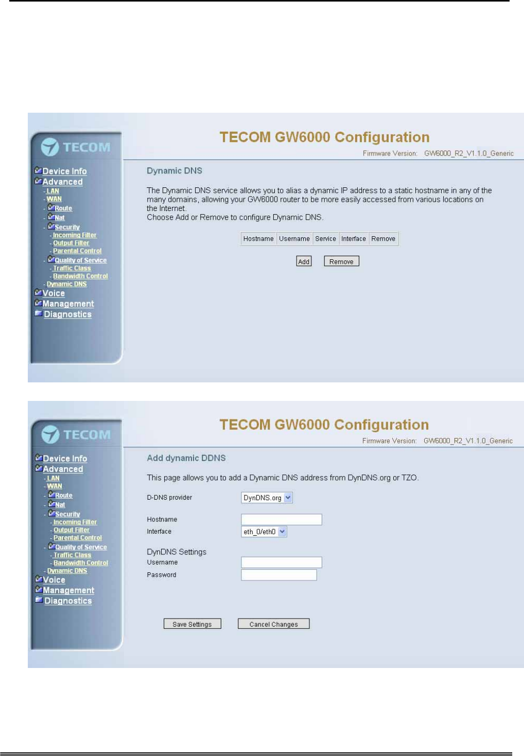
6.4.7 Dynamic DNS
The Dynamic DNS service allows you to alias a dynamic IP address to a static
hostname in any of the many domains, allowing your DSL router to be more easily
accessed from various locations on the Internet. (Figure 6-20-1, Figure 6-20-2)
Figure 6-20-1. Advanced Setup – Dynamic DNS
Figure 6-20-2. Advanced Setup – Dynamic DNS - Add
Copy Right 2006 Tecom, Co. LTD. All rights reserved Page 47 of 107
Administrative Guide Configuration
6.5 Wireless
This directory display only when wireless card is installed in your EUT board. Use
the Wireless screen to configure the EUT for wireless access. It is separated into 6
parts:
z Basic
z Security
z MAC Filter
z Wireless Bridge
z Advanced
z Station Info
The configurable items for each part would be described in the following.
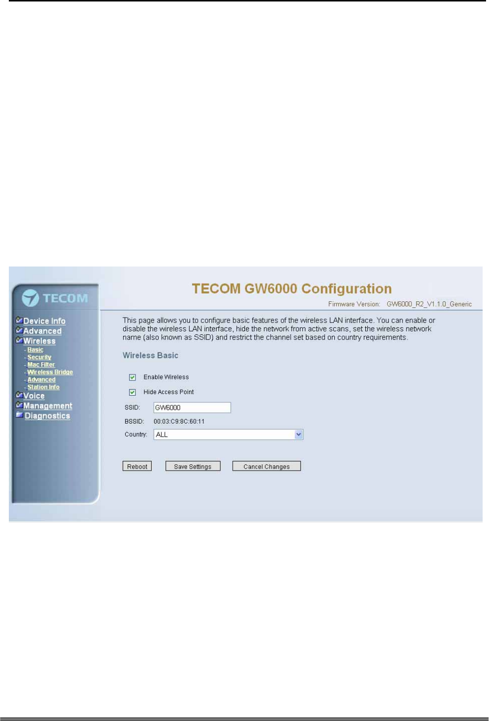
6.5.1 Basic
The page (Figure 6-21) allows you to configure basic feature of the wireless LAN
interface. You can enable or disable the wireless LAN interface, hide the network from
active scans, set the wireless network name (also known as SSID) and restrict the
channel set based on country requirement.
Figure 6-21. Wireless – Basic
6.5.2 Security
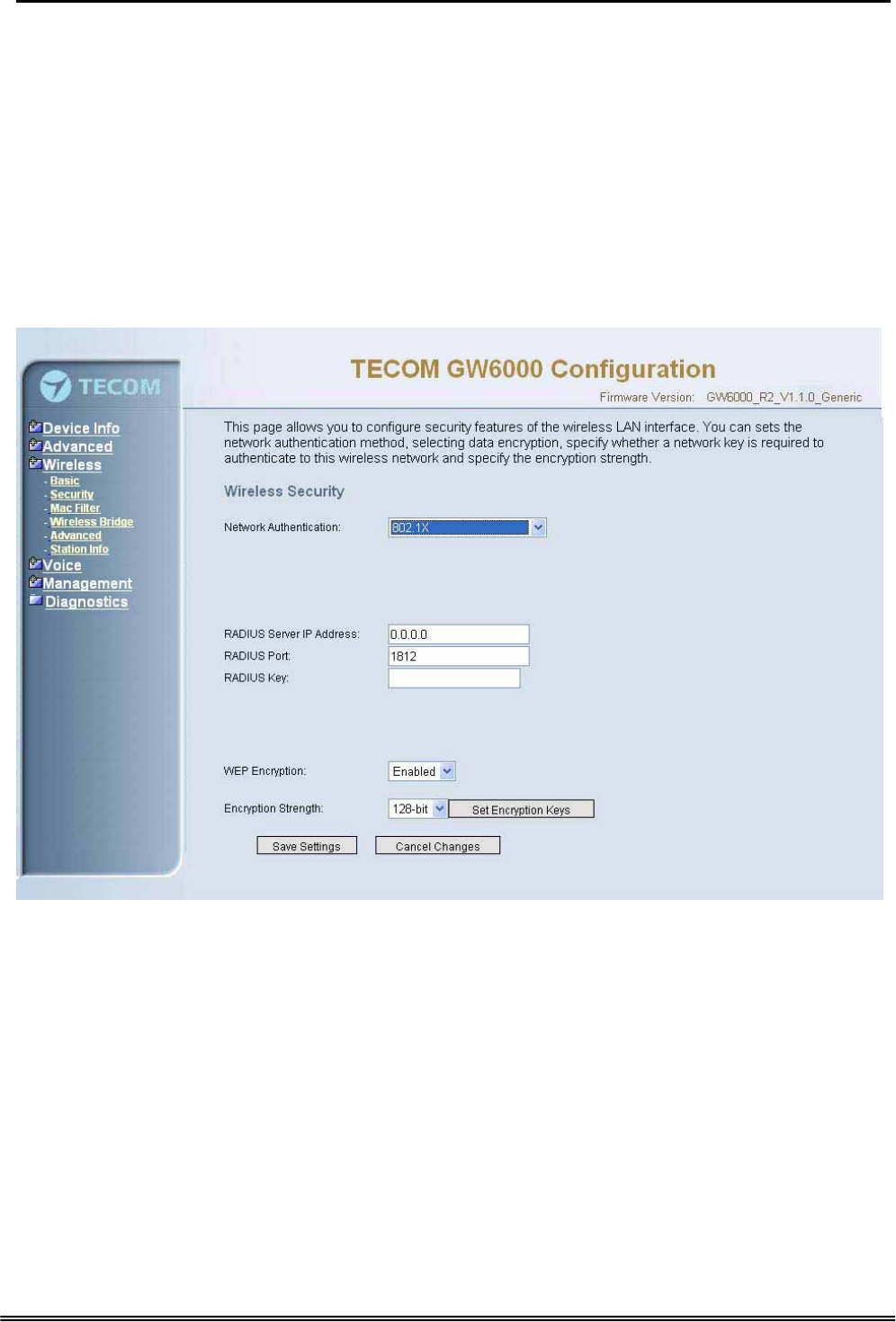
The page allows you to configure security features of the wireless LAN interface. You
can set the network authorization method, select data encryption, specify whether a
network key is required to authenticate to this wireless network and specify the
encryption strength.
The following items will be configured in the page:
Network Authentication: Set the network Authentication method. 802.1X and WPA
require setting valid RADIUS parameters. WPA-PSK requires a valid WPA Pre-Shared
Key to be set. (Figure 6-22-1)
Copy Right 2006 Tecom, Co. LTD. All rights reserved Page 48 of 107
Administrative Guide Configuration
802.1X: As the IEEE standard for access control for wireless and wired LANs, 802.1x
provides a means of authentication and authorizing devices to attach to a LAN port.
This standard defines the Extensible Authentication Protocol (EAP), which uses a
central authentication server to authenticate each user on the network.
WPA/WPA2: The Wi-Fi Alliance put together WPA/WPA2 as a data encryption method
for 802.11 wireless LANs. WPA is an industry-supported, pre-standard version of
802.11i utilizing the Tempoal Key Integrity Protocol (TKIP), which fixes the problems
of WEP, including using dynamic keys.
WPA/WPA2 Pre-Shared Key: Set the WPA/WPA2 Pre-Shared Key (PSK).
WPA/WPA2 Group Rekey Interval: Set the WPA/WPA2 Group Rekey Interval in
seconds. Leave blank or set to zero to disable periodic re-keying.
Figure 6-22-1. Wireless – Security
Radius Server: Set the IP address of the RADIUS server to use for authentication and
dynamic key derivation.
RADIUS Server is responsible for receiving user connection requests, authenticating
the user, and then returning all of the configuration information necessary for the client
to deliver the server to the user.
Radius Port: Sets the UDP port number of the RADIUS server. The port number is
usually 1812 or 1645 and depends on the server.
Radius Key: Set the shared secret for the RADIUS connection.
WEP Encryption: Selecting Disabled disables WEP data encryption. Selecting
Enabled enables WEP data encryption and requires that a valid network key be set
and selected unless 802.1X is enabled.
Copy Right 2006 Tecom, Co. LTD. All rights reserved Page 49 of 107
Administrative Guide Configuration
WEP, short for Wired Equivalent Privacy, is a protocol for wireless LANs or local area
networks. This WEP is defined in the 802.11 Standard. WEP is designed so security
levels are maintained at the same level as the wired LAN. WEP’s aim is to provide
security by encrypting data over radio waves. WEP protects data as it’s transmitted
from one end point to another. WEP is used at two lowest layers, the data link and
physical layer. WEP is designed to make up for the inherent security in wireless
transmission as compared to wired transmission.
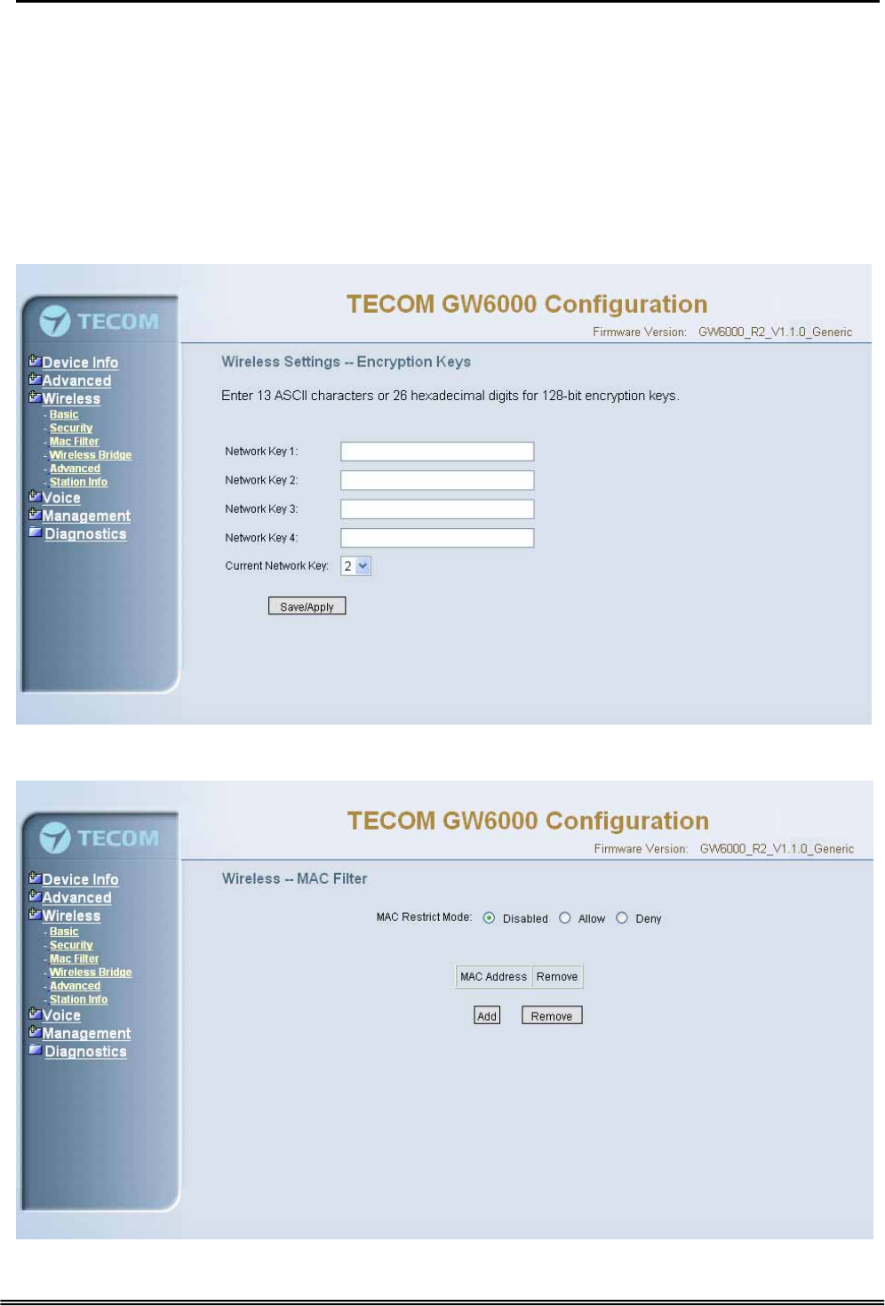
Shared Key Authentication: Set whether shared key authentication is required to
associate. A valid network key must be set and selected if required. (Figure 6-22-2)
Figure 6-22-2. Wireless – Security – Encryption Keys
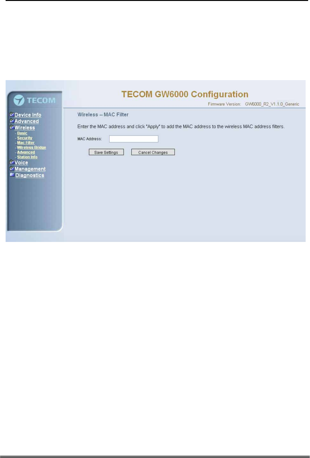
6.5.3 MAC Filter
Figure 6-23-1. Wireless – MAC Filter
Copy Right 2006 Tecom, Co. LTD. All rights reserved Page 50 of 107
Administrative Guide Configuration
This page allows users to Add/Remove hosts with the specified MAC addresses that
are able or unable to access the wireless network. When users decide to use Allow,
only the MAC addressed in the user-defined list can access the wireless network.
When users use Deny, only the user specified MAC addresses are unable to access
to wireless network. And if the Disable option is selected, all users will be able to
access to wireless network.
Note: The MAC addresses in the list would immediately take effect when Allow or
Deny is checked.
Figure 6-23-2. Wireless – MAC Filter – Allow/Deny
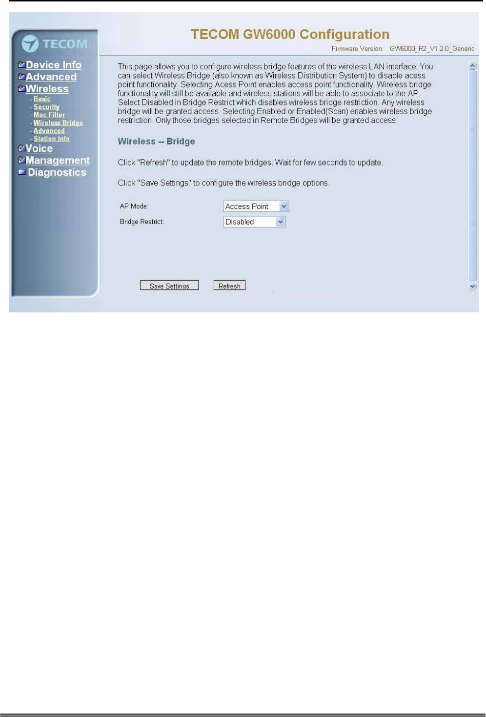
6.5.4 Wireless Bridge
It allows the users to configure wireless bridge features of the wireless LAN interface.
You can select Wireless Bridge (also known as Wireless Distribution System) to
disables access point functionality. Selecting Access Point enables access point
functionality. Wireless bridge functionality will still be available and wireless stations
will be able to associate to the AP. Select Disabled in Bridge restricts which disables
wireless bridge restriction. Any wireless bridge will be granted access. Selecting
Enabled or Enabled (Scan) enables wireless bridge restriction. Only those bridges
selected in Remote Bridges will be granted access.(Figure 6-24).
Copy Right 2006 Tecom, Co. LTD. All rights reserved Page 51 of 107
Administrative Guide Configuration
Figure 6-24. Wireless – Wireless Bridge
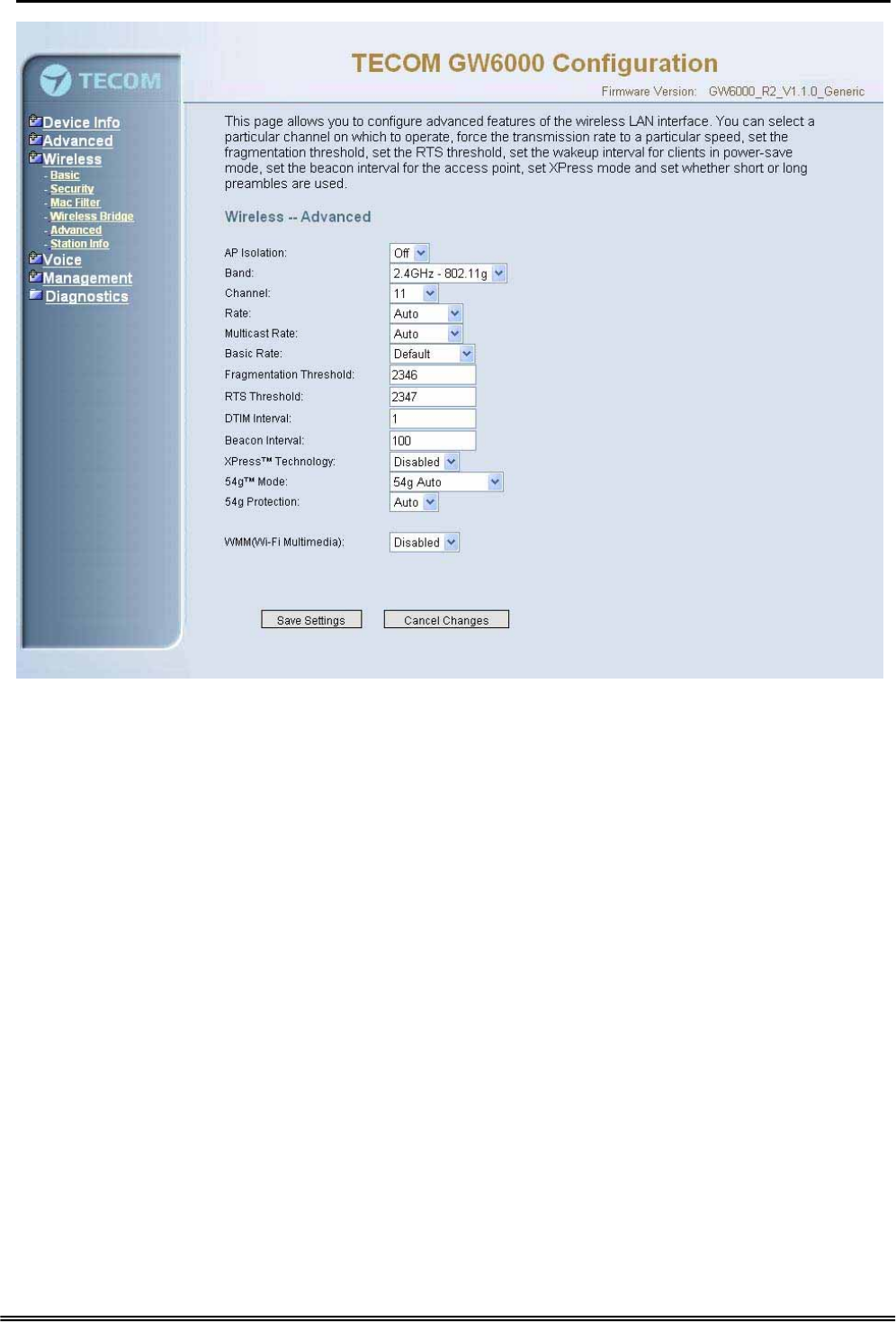
6.5.5 Advanced
It allows you to configure advanced features of the wireless LAN interface. You can
select a particular channel on which to operate, force the transmission rate to a
particular speed, set the fragmentation threshold, set the RTS threshold, set the wakeup
interval for clients in power-save mode, set the beacon interval for the access point, set
XPress mode and set whether short or long preambles are used
Channel: Select the appropriate channel from the list provided to correspond with your
network settings. All devices in your wireless network must use the same channel in
order to function correctly.
Rate: The default setting is Auto. The range is from 1 to 54Mbps. The rate of data
transmission should be set depending on the speed of your wireless network. You can
select from one transmission speed, or keep the default setting, Auto, to have the IAD
automatically use the fastest possible data rate.
Multicast Rate: The default setting is 54Mbps. The range is from 1 to 54Mbps. The
rate of data transmission should be set depending on the speed of your wireless
network. You can select from one transmission speed, or keep the default setting, to
have the IAD automatically use the fastest data rate for multicast packets.
Basic Rate: Select the basic rate that wireless clients must support.
Fragmentation Threshold: This value should remain at its default setting of 2346. The
range is 256~2346 bytes. It specifies the maximum size for a packet before data is
fragmented into multiple packets. If you experience a high packet error rate, you may
slightly increase the Fragmentation Threshold. Setting this value too low may result in
poor network performance. Only minor modifications of this value are recommended.
Copy Right 2006 Tecom, Co. LTD. All rights reserved Page 52 of 107
Administrative Guide Configuration
Figure 6-25. Wireless – Advanced
RTS Threshold: This value should remain at its default setting of 2347. The range is
0~2347 bytes. Should you encounter inconsistent data flow, only minor modifications
are recommended. If a network packet is smaller than the packet RTS threshold size,
the RTS/CTS mechanism will not be enabled. The IAD sends Request of Send (RTS)
frames to a particular receiving station and negotiates the sending of a data frame.
After receiving an RTS, the wireless station responds with a Clear to Send (CTS)
frame to acknowledge the right to begin transmission.
DTIM Interval: The default value is 3. This value, between 1 and 255 milliseconds,
indicates the interval of the Delivery Traffic Indication Message (DTIM). A DTIM field is
a countdown field informing clients of the next window for listening to broadcast and
multicast messages. When the router has buffered broadcast or multicast for
associated clients, it sends the next DTIM with a DTIM Interval value. Its clients hear
the beacons and awaken to receive the broadcast and multicast message.
Beacon Interval: The default value is 100. Enter a value between 1 and 65535
milliseconds. The Beacon Interval value indicates the frequency interval of the beacon.
A beacon is a packet broadcast by the router to synchronize the wireless network.
XPress™ Technology: Select to enable/disable this proprietary mode.
54g™ Mode: Select the mode to 54g Auto for the widest compatibility. Select the
mode to 54g Performance for the fastest performance among 54g certified equipment.
Set the mode to 54g LRS if you are experiencing difficulty with legacy 802.11b
equipment.
Copy Right 2006 Tecom, Co. LTD. All rights reserved Page 53 of 107
Administrative Guide Configuration
54g protection: In Auto mode the IAD will use RTS/CTS to improve 802.11g
performance in mixed 802.11g/802.11b networks. Turn protection off to maximize
802.11g throughput under most conditions.
WMM (WiFi Multimedia): Select to enable/disable the support.(Figure 6-25)
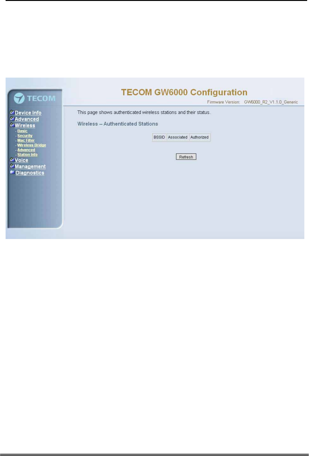
6.5.6 Station Info
Authenticated wireless stations and their status will be shown here.(Figure 6-26)
Figure 6-26. Wireless – Station Info
Copy Right 2006 Tecom, Co. LTD. All rights reserved Page 54 of 107

Administrative Guide Configuration
6.6 Voice
Use the Voice screen to configure the EUT function related parameters. It allows
system administrator to configure the following topics:
z Phone
- Phone Extension
- Extension Linekey
z Trunk
- IP Trunk
- Trunk Group
- Answering Positions
- Call Restriction Table
- Call Routing Table
z System
- Numbering Plan
- Service Mode
- Transmission
- IG Dynamic Discovery
- IG Expansion Table
z Voice Mail
- General
- Extension
- Holiday
- Advanced
The configurable items for each part would be described in the following.
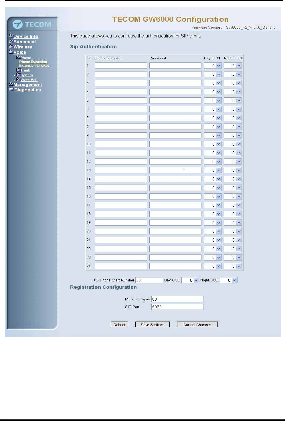
6.6.1 Phone
Use the phone extension screen to configure EUT’s phone extension authentication
and IP2007’s extension line key default setting.
6.6.1.1 Phone Extension
The EUT combines Proxy and Registrar servers in its application. The all phones
registered to the internal Registrar are set here. (Figure 6-27)
Copy Right 2006 Tecom, Co. LTD. All rights reserved Page 55 of 107
Administrative Guide Configuration
Figure 6-27. Voice – Phone – Phone Extension
SIP Authentication: It provides 24 IP phones registered.
Phone Number: The phone number is a station number. If it conflicts with the setting
in Numbering Plan, it fails to add or make the change. Its value range is limited by
Start Extension Number and End Extension Number settings in Numbering Plan
page.
Password: The user password of this phone. The length is up to 24 digits or
characters. It’s used for Digest Authentication.
Copy Right 2006 Tecom, Co. LTD. All rights reserved Page 56 of 107
Administrative Guide Configuration
Day COS: The field assigns Class of Service for day mode operation. Acceptable
values are 0-7. At default, all extensions are unrestricted.
Night COS: The field assigns Class of Service for night mode operation. Acceptable
values are 0-7. At default, all extensions are unrestricted.
FXS Phone Start Number: It shows the FXS phone number. It’s programmed in
System – Numbering Plan.
Registration Configuration
Minimal Expire: the minimum refresh interval registrar time supported for these IP
phones managed by the Gateway Server.
SIP Port: The Gateway Server listens for requests on the SIP port. This port is used
for UDP application and 5060 is its recommended value.
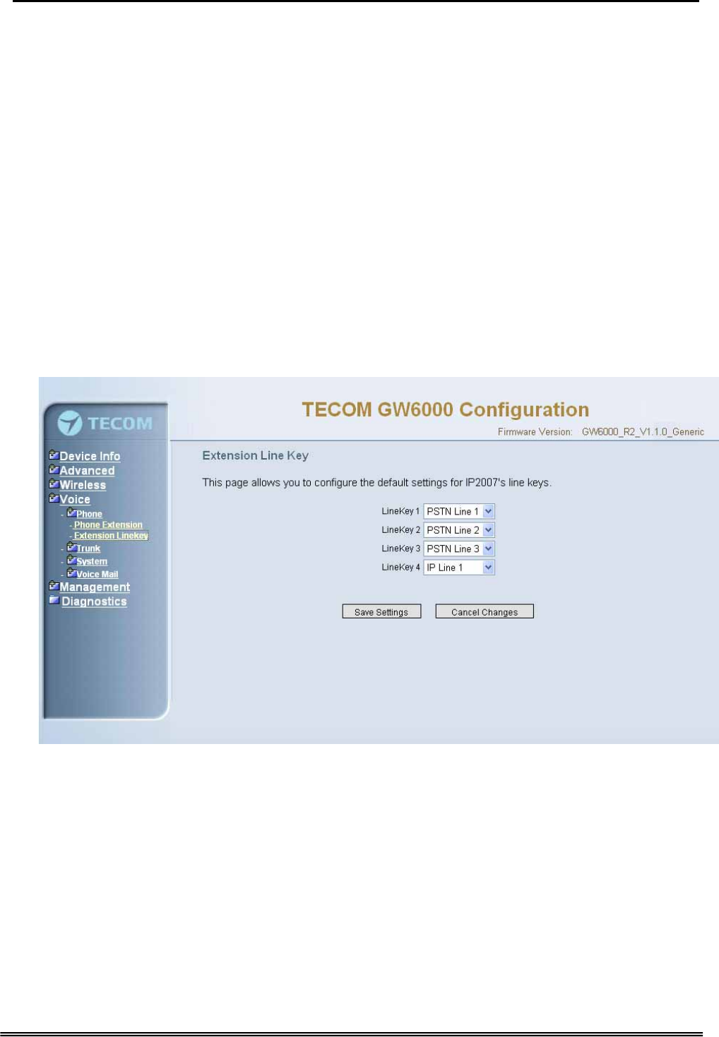
6.6.1.2 Extension Linekey
This page allows you to configure the default settings for IP2007’s linekeys. While a
new-allocated IP2007 is registering to IG, IG will send these settings to the
phone.(Figure 6-28)
Figure 6-28. Voice – Phone – Extension Linekey
6.6.2 Trunk
Use the Trunk screen to configure the PSTN/IP Trunk function related parameters. It is
separated into 5 parts:
z IP Trunk
z Trunk Group
z Answering Positions
z Call Restriction Table
z Call Routing Table
Copy Right 2006 Tecom, Co. LTD. All rights reserved Page 57 of 107

Administrative Guide Configuration
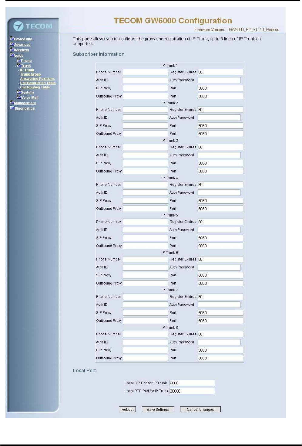
6.6.2.1 IP Trunk
This page allows you to configure the proxy and registration server of IP Trunk, up to 8
lines of IP Trunk are supported. (Figure 6-29)
Copy Right 2006 Tecom, Co. LTD. All rights reserved Page 58 of 107
Administrative Guide Configuration
Figure 6-29. Voice – Trunk – IP Trunk
Copy Right 2006 Tecom, Co. LTD. All rights reserved Page 59 of 107

Administrative Guide Configuration
Subscriber Information
Trunk Number: The assigned phone number from Uplink Server.
Register Expires: how long the Gateway sends REGISTER to uplink registrar server.
It counts based on second.
Auth ID: The Account ID of registration to uplink server. It’s used for Digest
Authentication.
Auth Password: The Password of registration to uplink server. It’s used for Digest
Authentication.
SIP Proxy: the position of uplink registrar server. Digital IP address and domain
name are all supported.
SIP Proxy Port: SIP signal port of uplink registrar server.
Outbound Proxy: the address of uplink outbound proxy server. All sip request
packet will be sent to this server that will determine their next hops.
Outbound Proxy Port: SIP signal port of uplink outbound proxy server.
Local Port
Local SIP Port for IP Trunk: SIP control signal packet Port of IP Trunk Client.
Local RTP Port for IP Trunk: Real-Time Protocol packet Port of IP Trunk Client. It’s
the start RTP port address for these IP Trunks.
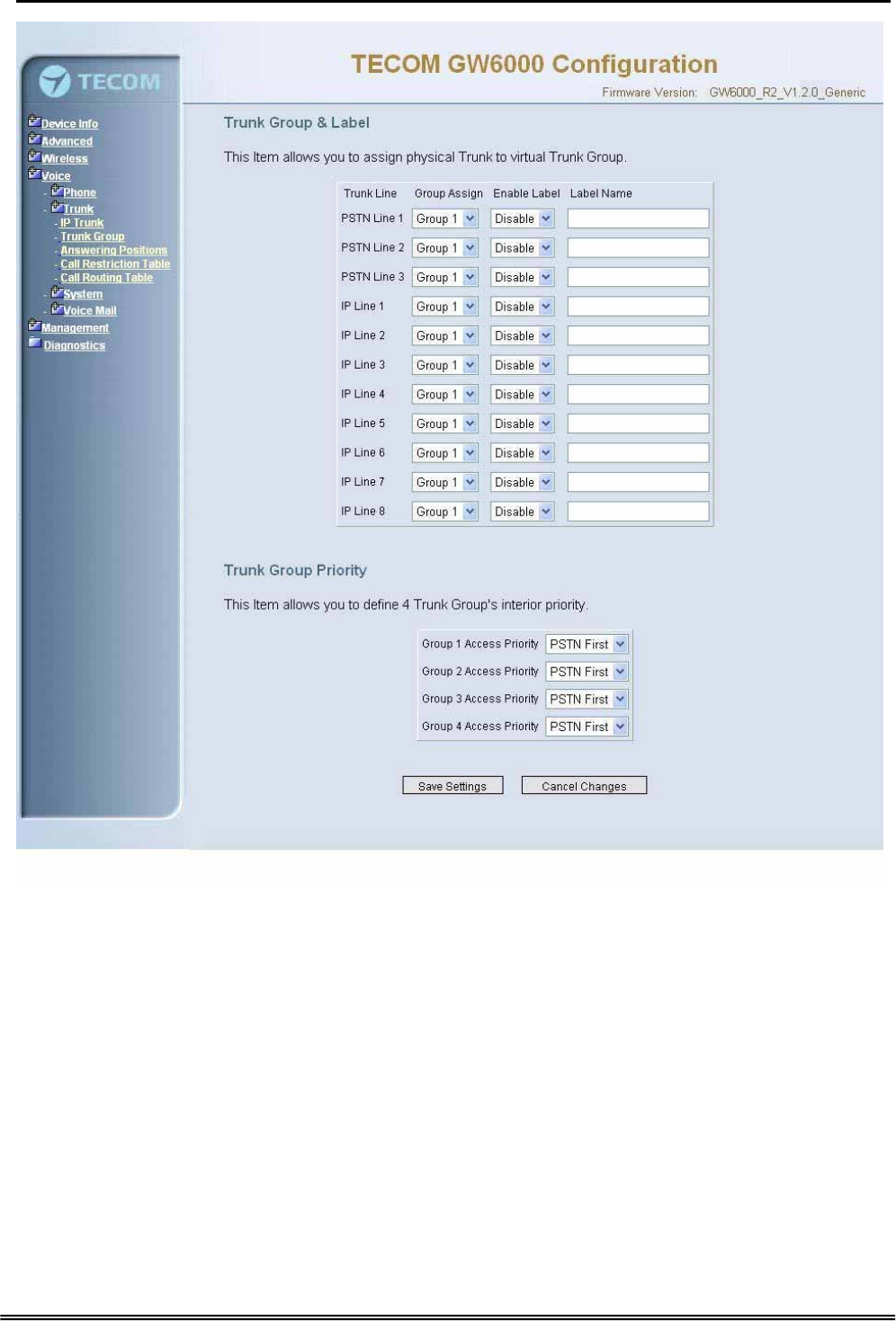
6.6.2.2 Trunk Group
This page allows you to configure the virtual Trunk Group, up to 4 Trunk Groups are
supported.(Figure 6-30)
Trunk Group & Label
This item allows you to assign physical Trunk to virtual Trunk Group. And you can
configure your personal string as incoming Caller ID number. For three PSTN lines
and eight IP lines you can choose from Group1 to Group 4.
Trunk Group Priority
This Item allows you to define 4 Trunk Group's interior priority. For four groups you
can choose IP first or PSTN first. This will take effect if call routing entry’s
destination has been set as Group choice.
Copy Right 2006 Tecom, Co. LTD. All rights reserved Page 60 of 107
Administrative Guide Configuration
Figure 6-30. Voice – Trunk –Trunk Group
Copy Right 2006 Tecom, Co. LTD. All rights reserved Page 61 of 107
Administrative Guide Configuration
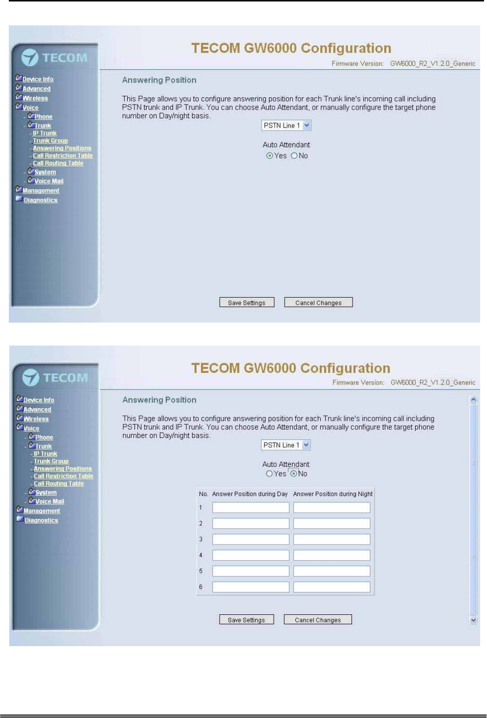
6.6.2.3 Answering Positions
Figure 6-31-1. Voice – Trunk – Answering Positions – AA(Yes)
Figure 6-31-2. Voice – Trunk – Answering Positions – AA(No)
Copy Right 2006 Tecom, Co. LTD. All rights reserved Page 62 of 107

Administrative Guide Configuration
This Item allows you to configure answering position for each Trunk line including PSTN
trunk and IP Trunk. You can choose Auto Attendant, or manual configure the target
phone number on Day/night basis.
Auto Attendant: Yes/No.
Day Answering Position: 6 extension numbers maximum
Night Answering Position: 6 extension numbers maximum
If choose Auto Attendant as Yes, an idle VAA will auto-answer this incoming trunk call.
You can continue your operation by following its indicative words. Otherwise some
extension will be called and ringing. If you pick up one of them, the other extensions will
stop ringing.(Figure 6-31)
6.6.2.4 Call Restriction Table
This page allows you to configure the call restriction table. If you choice YN in "Trunk
Access" option, it means that the entry is used in both trunk access and call routing judge.
Y means that it is only valid in trunk access judge, and N is vice versa. Only the caller's
COS priority is higher than the entry's COS value, the call is allowed.
From/To
The allowed intervals are made up of a From and To entry which establish a
numeric range. For example, an entry of “From 1700” , “To 1800” would include the
following range of numbers as the leading: 1700, 1701, 1702, …1799, 1800. Each
From/To entry can be from 1 to 13 digits long and may contain any digit 0-9, or X (X
representing any digit). The :From” entry must be less than or equal to the “To”
entry.
Trunk Access
EUT checks the field only when a call matches the associated allowed interval.
If the field is set to “Y”, the entry is valid when the trunk is accessed previously. If
the field is set to “N”, the trunk isn’t accessed previously. The trunk will be accessed
through Call Routing Table. If he option is set to “YN”, the entry is valid no matter
the trunk is accessed or not previously.
COS
The COS setting is defined by the allowed intervals. “Y” allows an extension with
the COS or higher priority to dial the number(s) specified in that range.
Copy Right 2006 Tecom, Co. LTD. All rights reserved Page 63 of 107
Administrative Guide Configuration
Figure 6-32. Voice – Trunk – Call Restriction Table
Copy Right 2006 Tecom, Co. LTD. All rights reserved Page 64 of 107
Administrative Guide Configuration
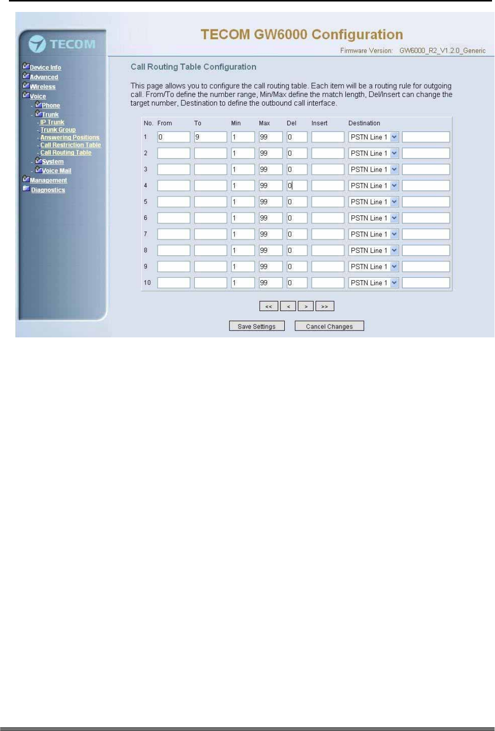
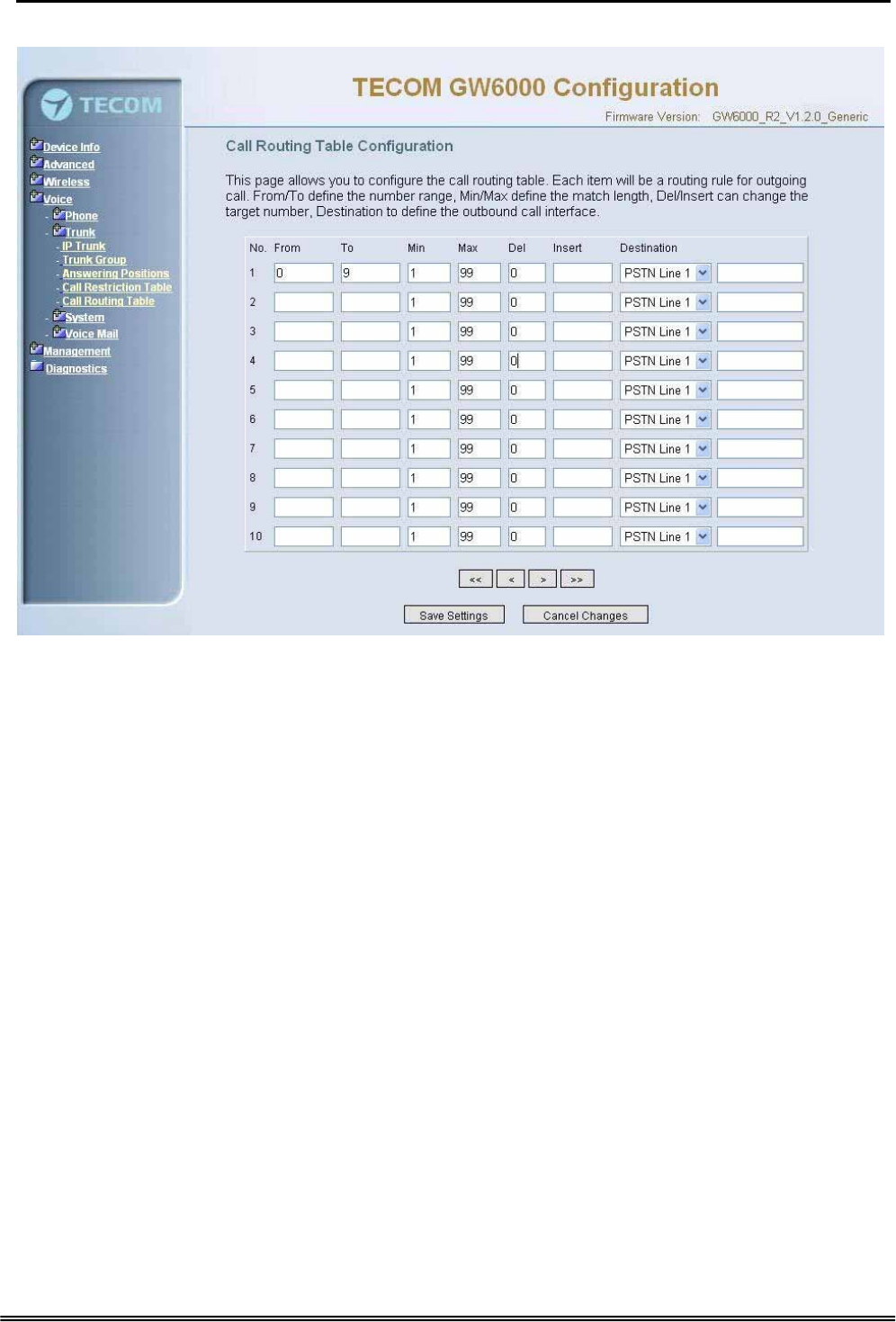
6.6.2.5 Call Routing Table
Figure 6-33. Voice – Trunk – Call Routing Table
This page allows you to configure the call routing table. Each item will be a routing rule
for outgoing call. From/To define the number range, Min/Max define the match length,
Del/Insert can change the target number, Destination to define the outbound call
interface. You can click the buttons under the table to choose pages.
In the Destination field, the drop list includes a particular option: “IG Expansion”.
When selecting “IG Expansion”, the next field is a drop list, the drop list contains the
founded IG name which is maintained by the EUT, and you can select a suitable IG
name to route your calls (Figure 6-33).
6.6.3 System
Use the System screen to configure the System function related parameters. It is
separated into 4 parts:
z Numbering Plan
z Service Mode
z Transmission
z IG Dynamic Discovery
z IG Expansion Table
Copy Right 2006 Tecom, Co. LTD. All rights reserved Page 65 of 107
Administrative Guide Configuration
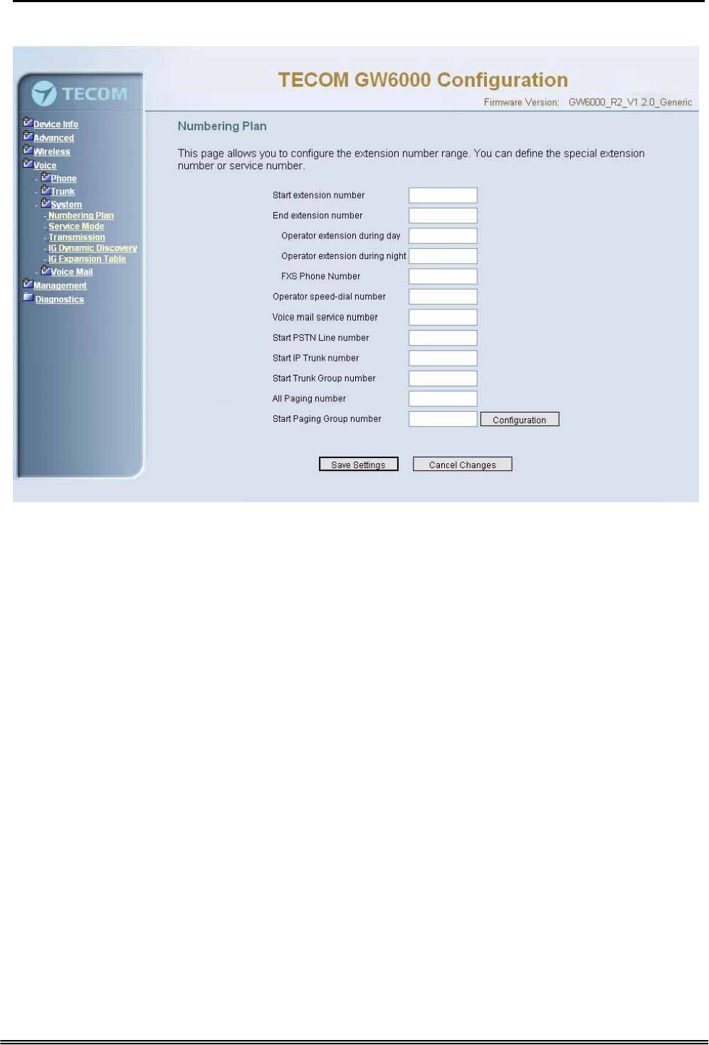
6.6.3.1 Numbering Plan
Figure 6-34. Voice – System – Numbering Plan
This page allows you to configure extension number range. You can also define some
special service numbers in the table.(Figure 6-33)
Start extension number: start phone number of system internal extension. All valid
extension number can’t be smaller than it.
End extension number: end phone number of system internal extension. All valid
extension number can’t be greater than it. If receiving an IP2007’s Plug & Play
request, IG will allocate the first unused number from this limited region.
Operator extension during day: system operator number. If dial Operator speed-
dial number, this extension will be called during day.
Operator extension during Night: system operator number. If dial Operator speed-
dial number, this extension will be called during night.
FXS Phone Number: It determines the FXS phone number.
Operator speed-dial number: If dial this number, the operator extension will be
called. Also it is limited on length 1 character.
Voice mail service number: If dial this number, internal user can enter IG’s vm
system and do some operations such as listening personal message.
Start PSTN Line number: IG provides 3 PSTN line at most. Every line has its own
internal alias number. You can dial these numbers directly to access PSTN trunks.
Start IP Trunk number: IG provide 8 IP Trunk line at most. Every line has also its
own internal alias number. You can dial these numbers directly to access IP Trunks.
Copy Right 2006 Tecom, Co. LTD. All rights reserved Page 66 of 107
Administrative Guide Configuration
Start Trunk Group number: IG provides 4 trunk groups at most. If dialing trunk
group number, IG will choose the first idle line for caller automatically.
All Paging number: If dialing this number, all internal IP2007s will be paged.
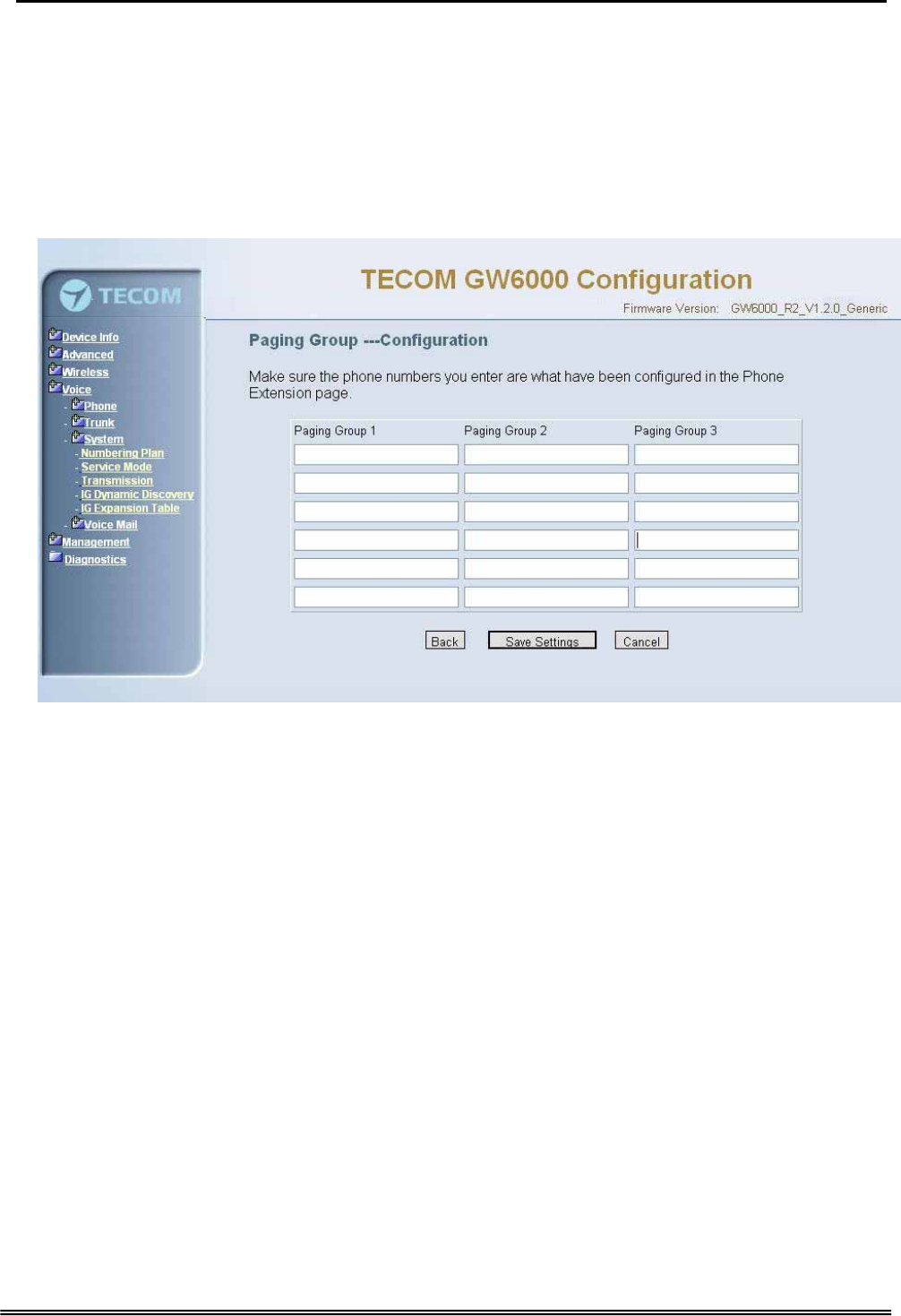
Start Paging Group number: 3 paging groups are defined in IG. If dialing a Paging
Group number, the call will page to all internal IP2007s of the called paging group.
While pressing “Configuration” in “Start Paging Group number”, it shows Paging Group
Configuration screen (Figure 6-34).
Figure 6-35. Voice – System – Numbering Plan – Paging Group
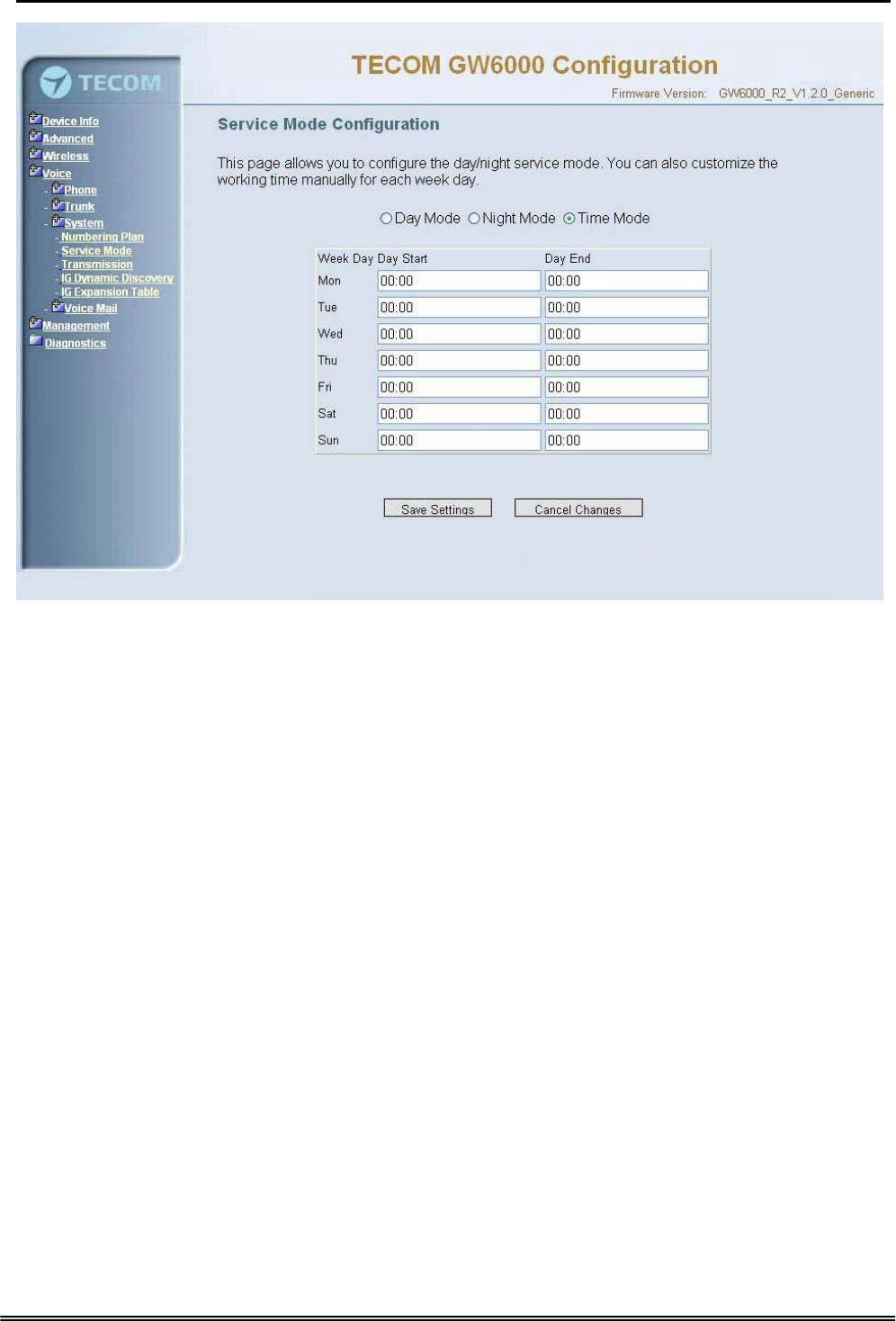
6.6.3.2 Service Mode
This page allows you to configure the day/night service mode. You can also customize
the working time manually for each weekday.
If you choose Time Mode, it’s for the specified day of week. The time is entered in 24-
hour format. Valid entries are 00:00 to 23:59 in 1-minute increments.(Figure 6-35)
Copy Right 2006 Tecom, Co. LTD. All rights reserved Page 67 of 107
Administrative Guide Configuration
Figure 6-36. Voice – System – Service Mode
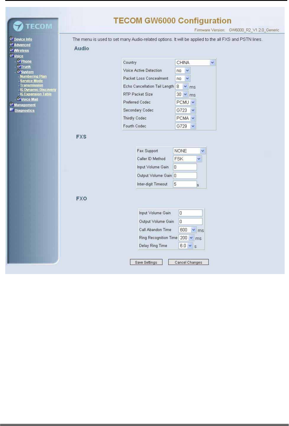
6.6.3.3 Transmission
This page allows you to configure the Audio, FXS, FXO settings. Click “Save Settings”
button to save the new configuration. Click “Cancel Changes” button you can cancel the
changes. (Figure 6-36)
Copy Right 2006 Tecom, Co. LTD. All rights reserved Page 68 of 107
Administrative Guide Configuration
Figure 6-37. Voice – System – Transmission
Audio: It is used to set many Audio-related options. It will be applied to the all FXS and
PSTN lines.
Country: It may be used to determine not only the Caller ID detection / transmission
method but also ring/tone cadence/frequency.
Voice Active Detection: Enable or Disable; VAD is a technique that detects the
absence of audio and conserved bandwidth by preventing the transmission of
“silence packets” over the network. Normally, this is set to On.
Packet Loss Concealment: Enable or Disable
Echo Cancellation Tail Length: Echo cancel time; 0 value disables Echo Canceller.
RTP Packet Size: 10/20/.../60 ms
Copy Right 2006 Tecom, Co. LTD. All rights reserved Page 69 of 107

Administrative Guide Configuration
Codec Priority: EUT can support different audio Codec (G711u, G711a, G723,
G729a) but only one is active at one time. You can choose “Preferred
Codec”, ”Secondary Codec”, ”Thirdly Codec” and ”Fourth Codec” properly.
FXS: It is used to set many FXS-related options.
Fax Support: The system supports FAX/modem tone detection with G.711 mode.
Call ID Method: The system provides the ability to detect the calling party
identification provided by PSTN lines. It also transmits the calling party identification
to POTS ports. There are four choices: NONE, DTMF_BR, DTMF_AR, FSK
Input Volume Gain: value range: -20 ~ 20. If the value increased 1, the actual
analog-voice will become louder 0.5dB. Otherwise the voice will become lower 0.5dB.
Output Volume Gain: value range: -20 ~ 20.
Inter-digit Timeout: Its range is from 0 to 30 seconds.
FXO: It is used to set many central office line options.
Input Volume Gain: value range: -20 ~ 20
Output Volume Gain: value range: -20 ~ 20
Call Abandon Time: For every PSTN/FXO call, system provides the facility to
monitor the call status. If the remote party hangs up, the ongoing call must be
terminated. The PSTN line monitor is done by the loop-break signal or busy tone.
The value range is: 100/200/…/1000 ms.
Ring Recognition Time: The timer determines the minimum ring duration
recognized as a valid incoming ring on a PSTN port. Shorter ring signals are ignored.
The timer range is 200ms to 60ms in 40ms increments.
Delay Ring Time: The timer is to allow the Central Office to send ICLID before the
call is answered. Once the timer expires, the programmed extensions will ring and
the ICLID number will be sent to the ringing extensions. The timer range is 3 to 6
seconds on 0.5 second increments.
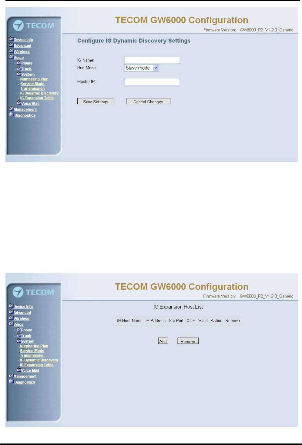
6.6.3.4 IG Dynamic Discovery
This page allows you to configure IG dynamic discovery settings.(Figure 6-37)
IG Name: The name of IG. It will be referred for the other IGs.
Run Mode: The mode that IG is running. IG can run in Master Mode or Slave Mode.
Master Mode: When IG is running in master mode, it maintains an IG list table.
When the master found that some slave IG changes its name or IP address, it will
broadcast to all of other slave IGs in this list and let them update their own IG list
table.
Slave Mode: When IG is running in slave mode, the master IG IP address should be
configured. When its name or IP address changed, it will inform the master IG. And
then the master IG will let other IG know this change.
Copy Right 2006 Tecom, Co. LTD. All rights reserved Page 70 of 107
Administrative Guide Configuration
Figure 6-38-1. Voice – System – IG Dynamic Discovery
6.6.3.5 IG Expansion Table
This page shows the all cooperated IGs. It can be got through IG Dynamic Discovery. It
also allows you to add the specified IG that our calls want to be routed into.
IG Host Name: The cooperated IG’s name.
IP Address: The cooperated IG’s IP address.
Sip Port: The cooperated IG’s SIP port.
COS: The cooperated IG’s Class of Service.
Valid: If setting “N”, it rejects the direct call from the cooperated IG.
Copy Right 2006 Tecom, Co. LTD. All rights reserved Page 71 of 107