Tecom Co GW5051 VOIP GATEWAY User Manual GW5051 Manual v0 2
Tecom Co Ltd VOIP GATEWAY GW5051 Manual v0 2
UserManual.wiki
>
Tecom Co
>
GW5051 User Manual
user manual
Navigation menu
Upload a User Manual
Namespaces
Wiki Guide
HTML
PDF
Info
Views
User Manual
Discussion / Help
Navigation
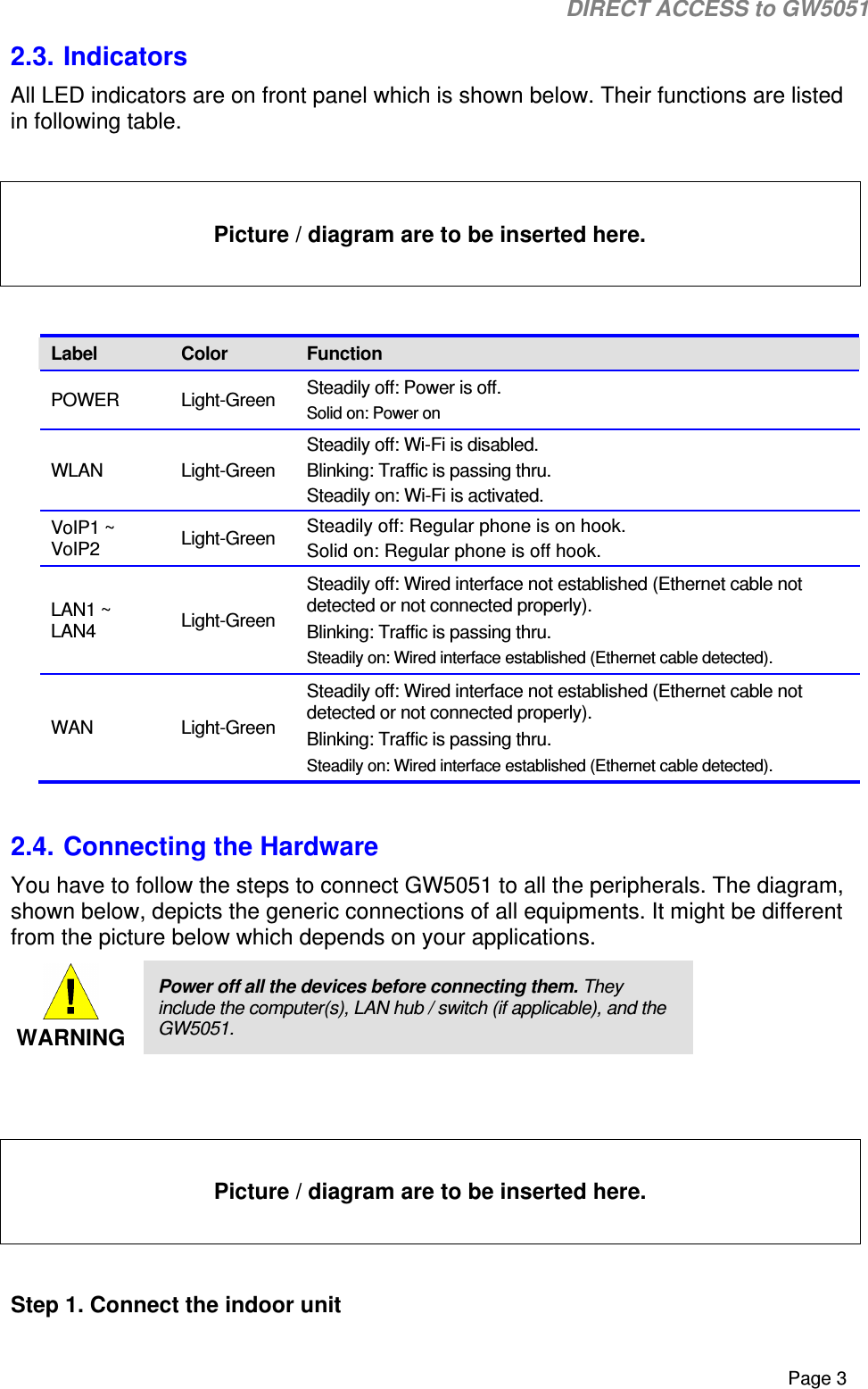
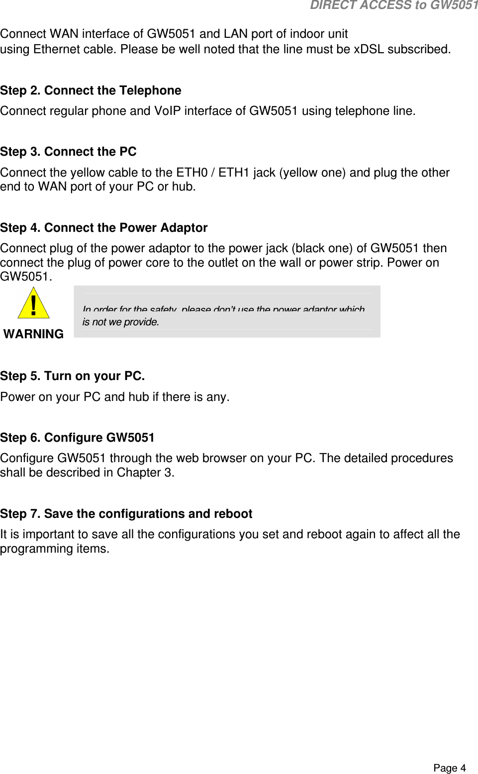

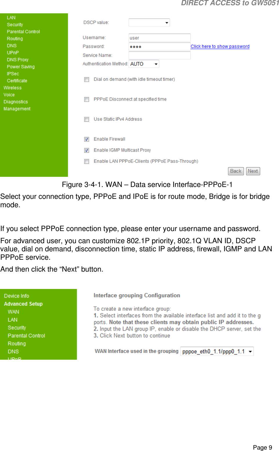
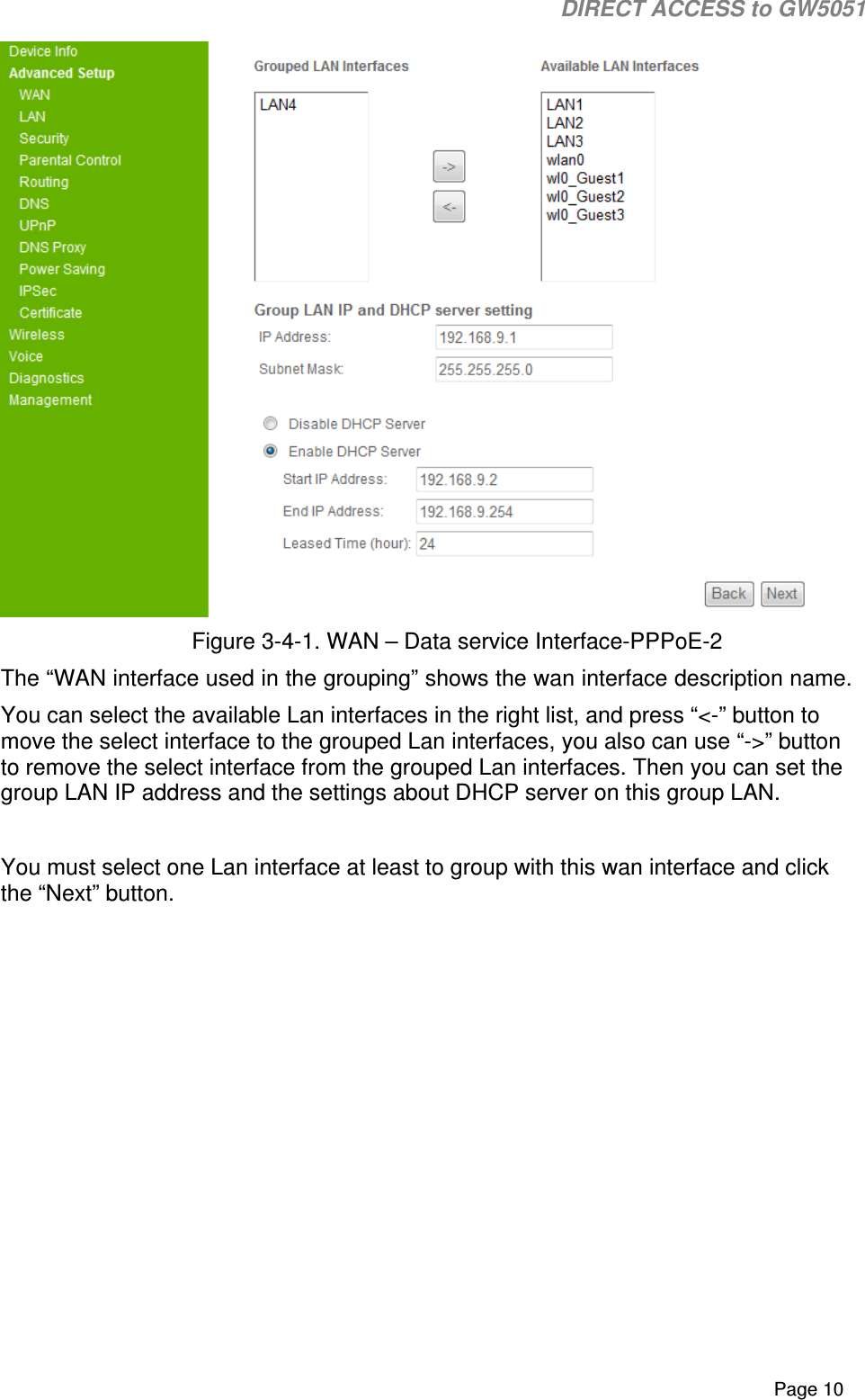
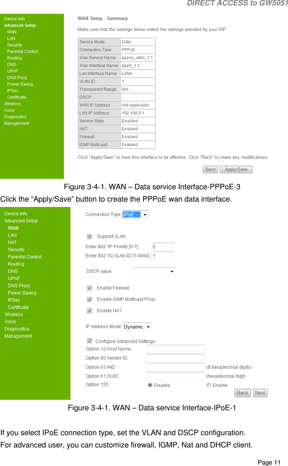
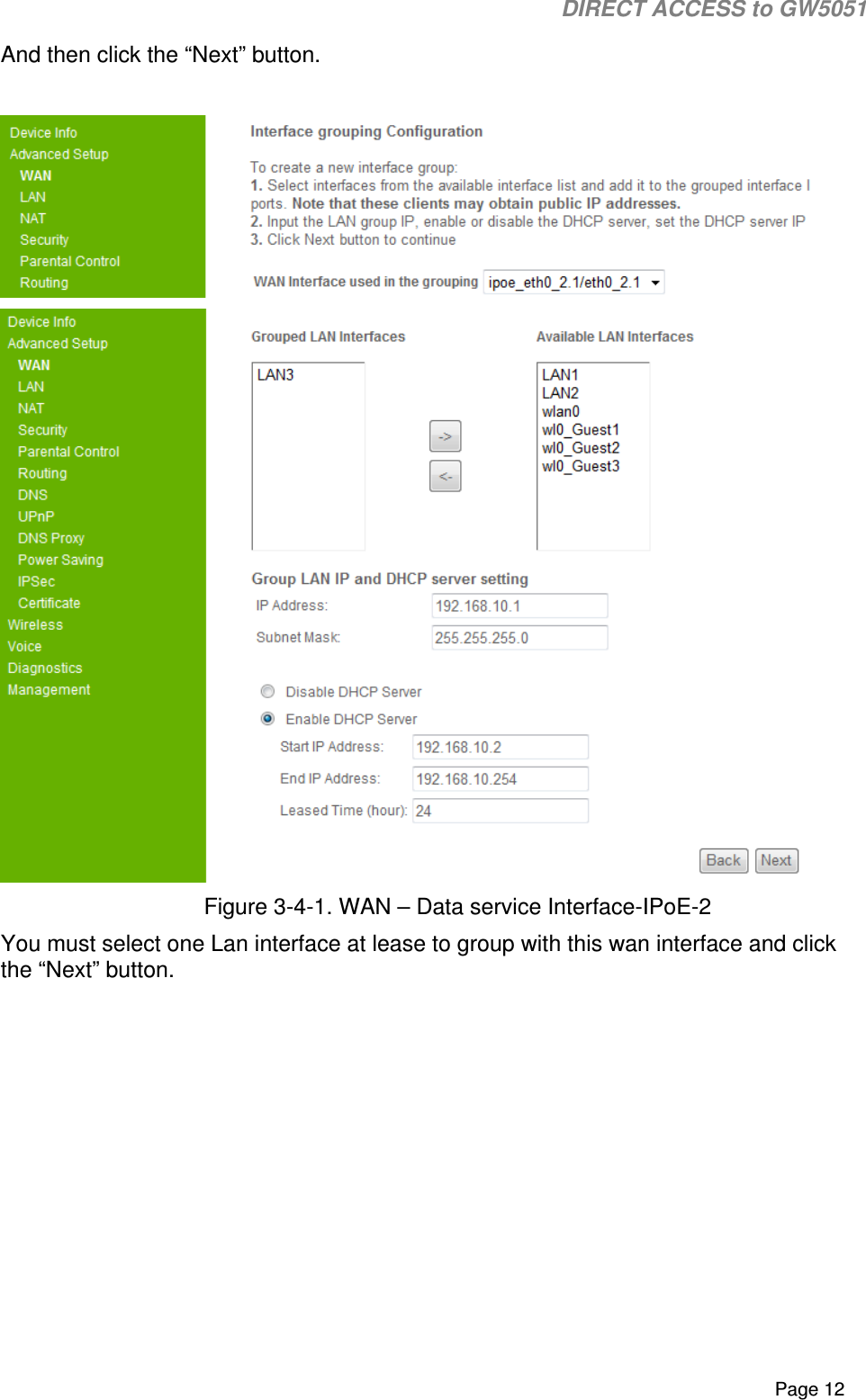
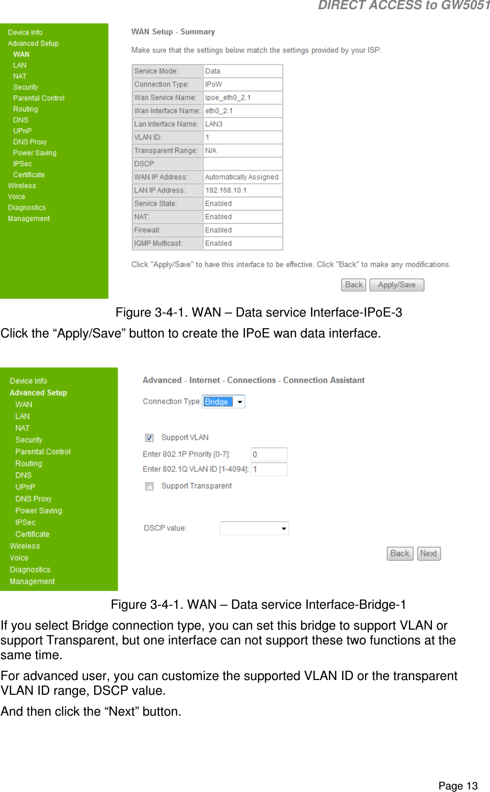
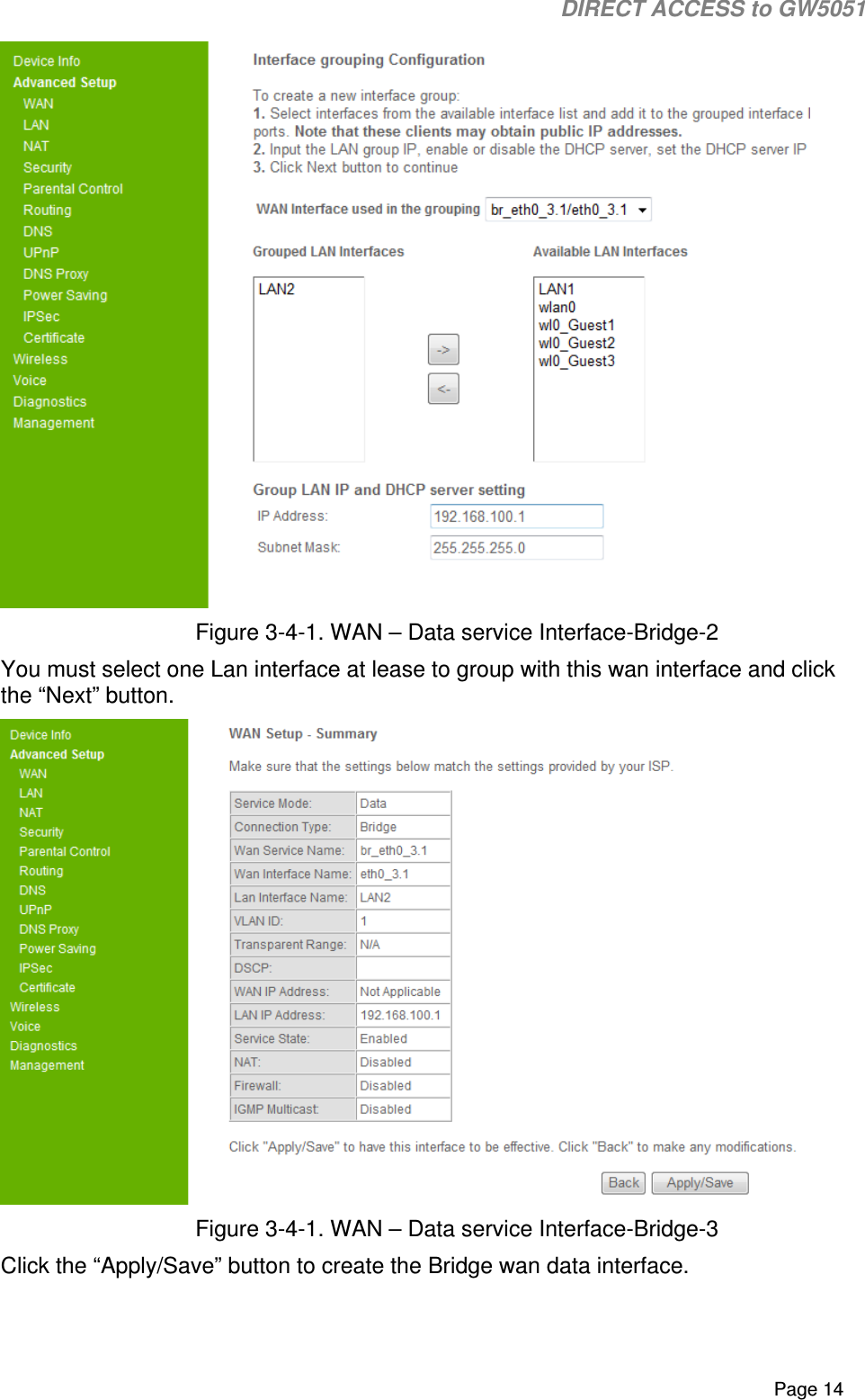
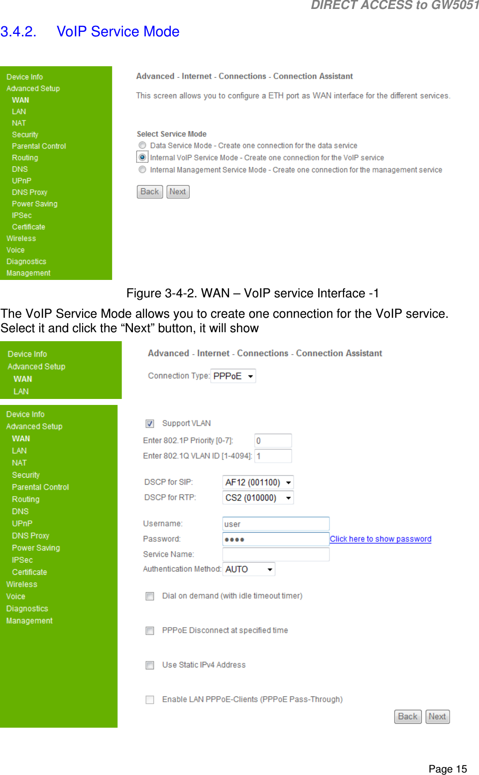
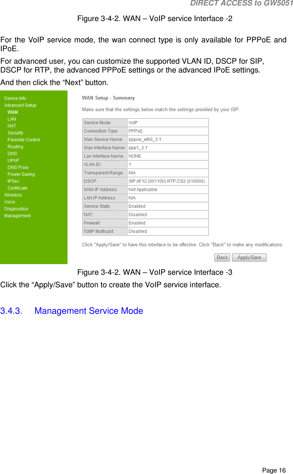
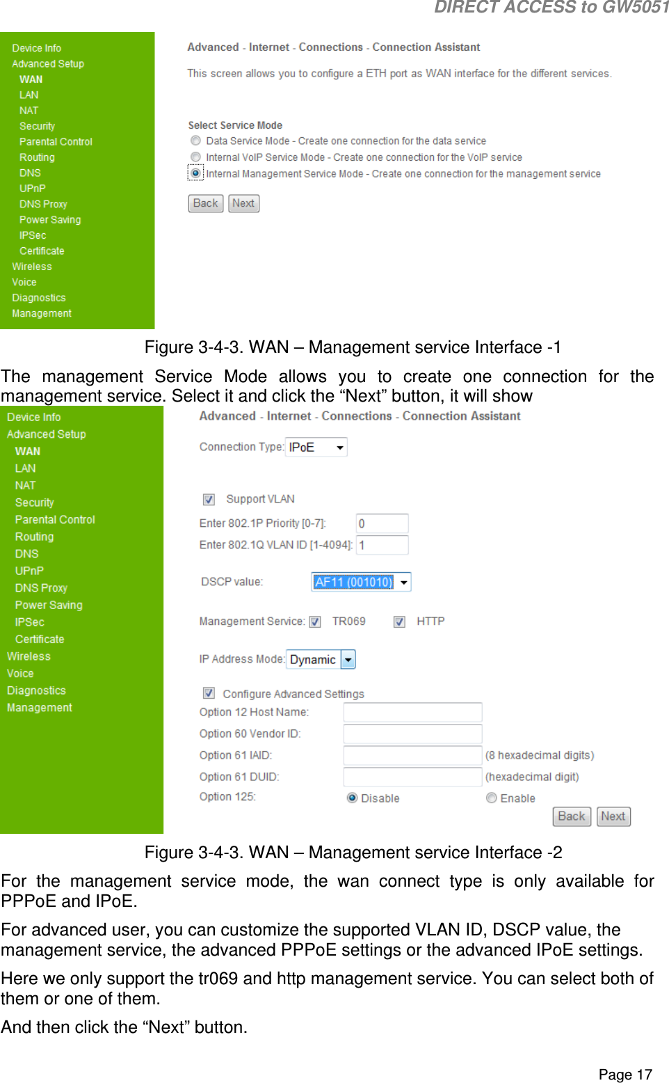
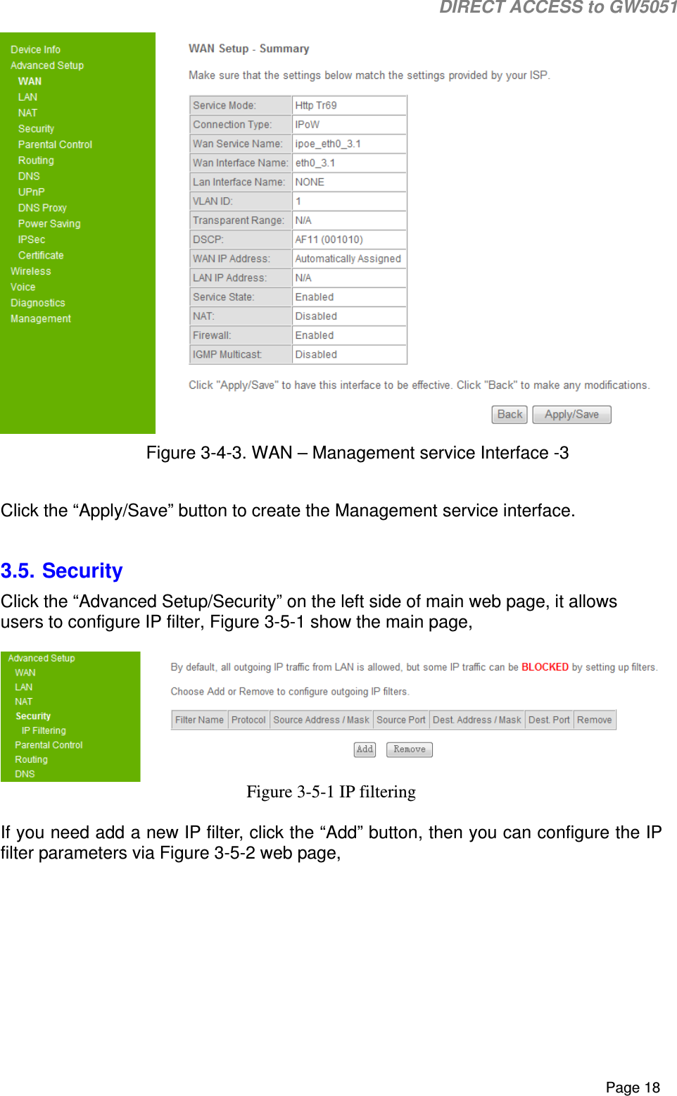
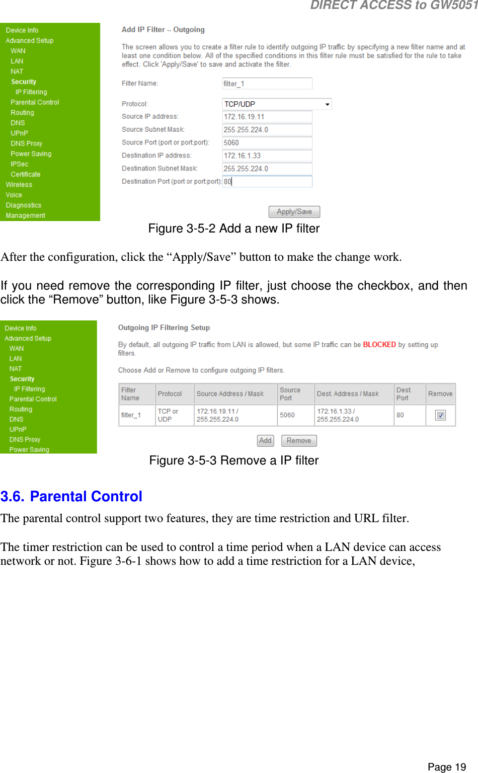
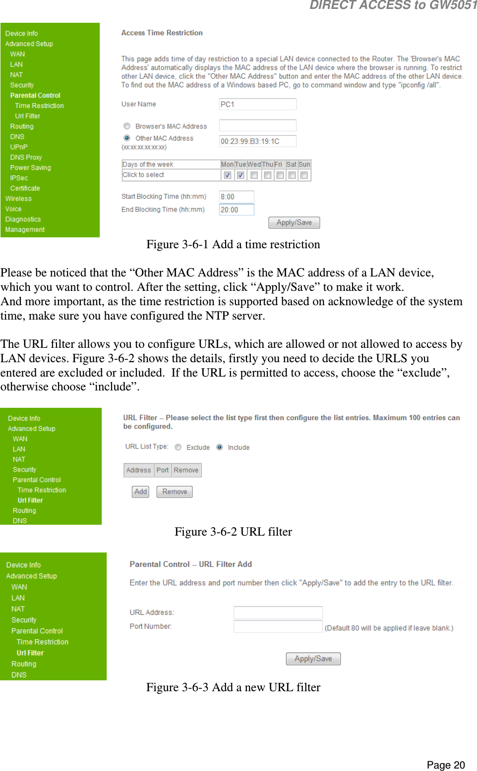
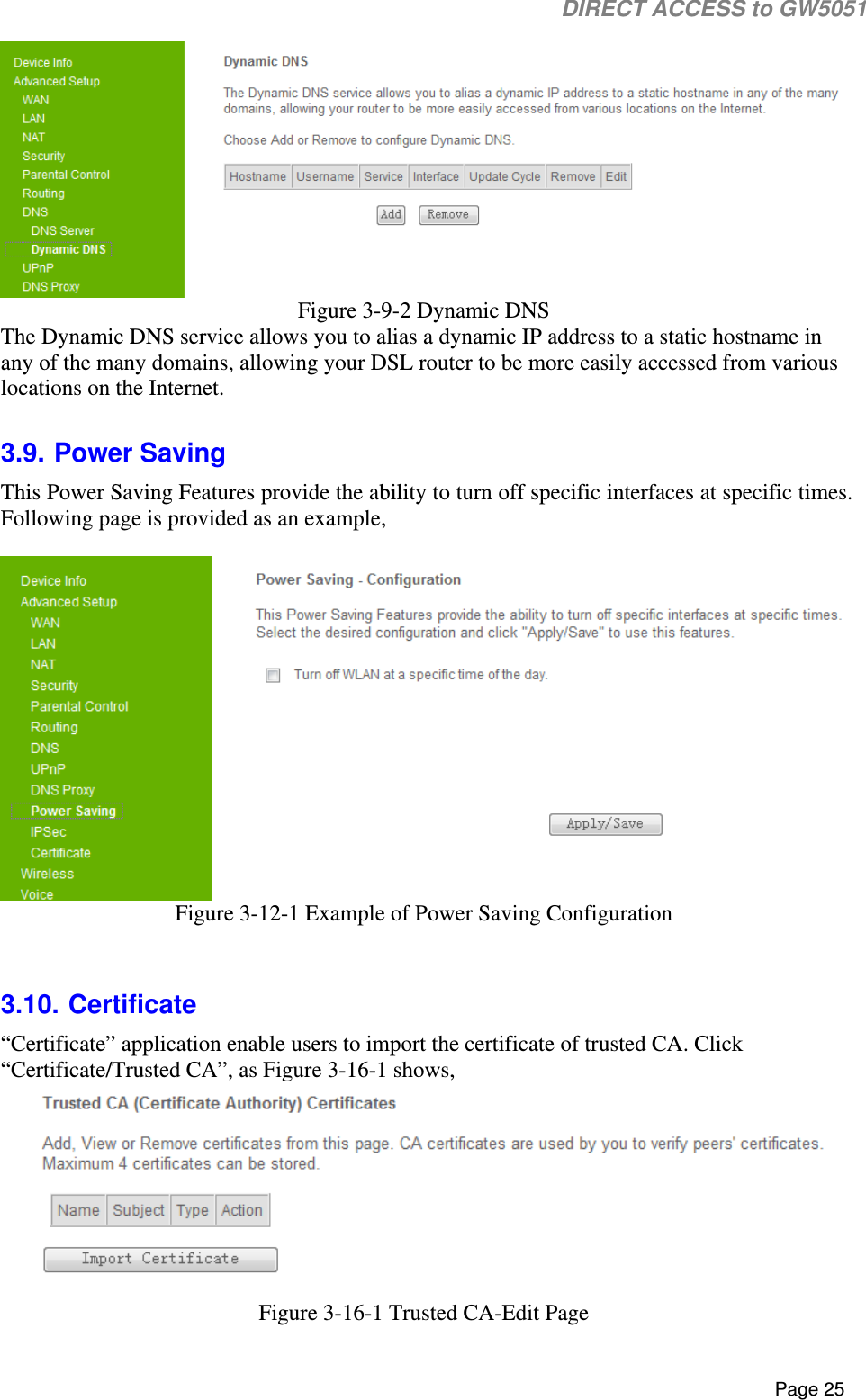
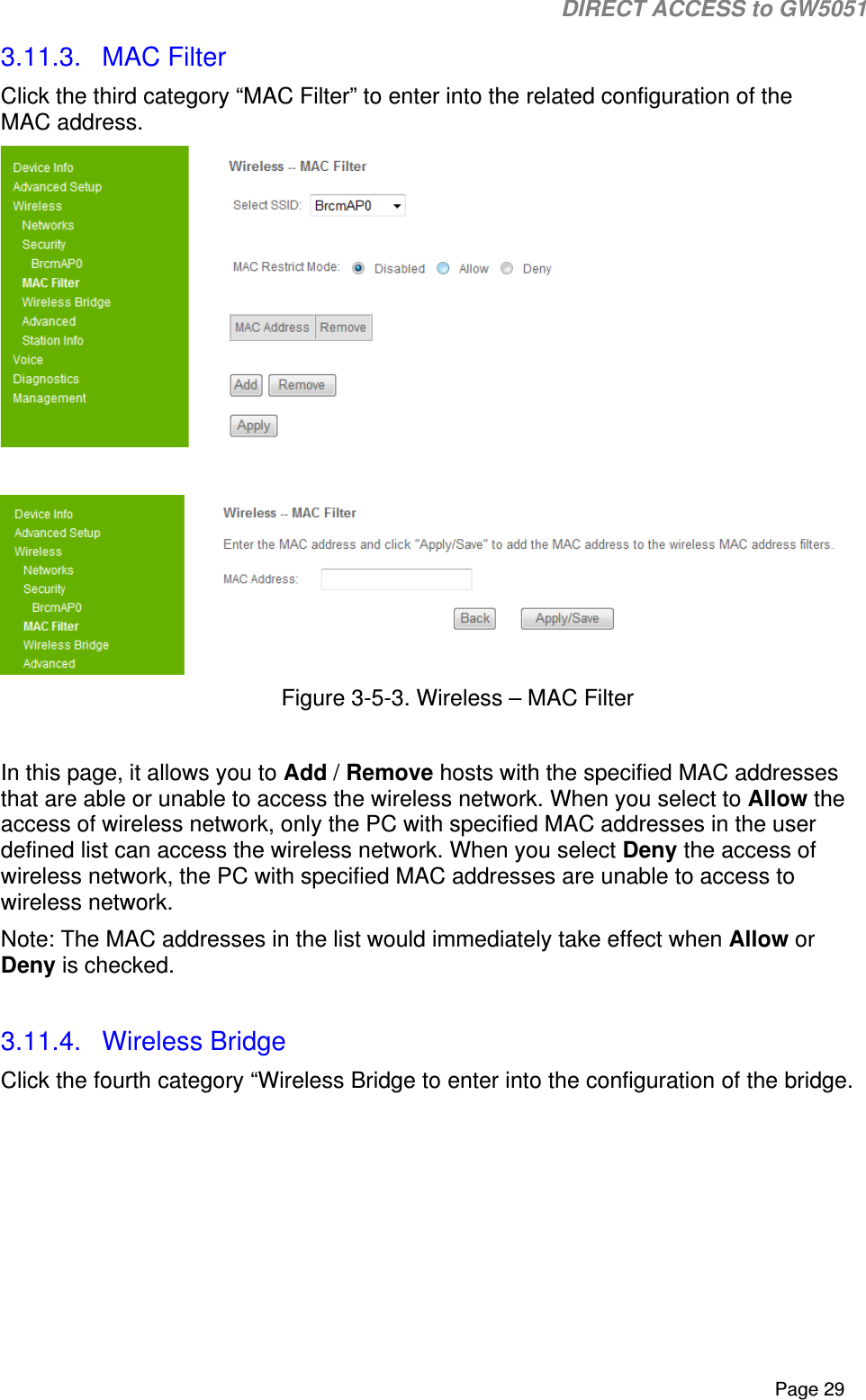
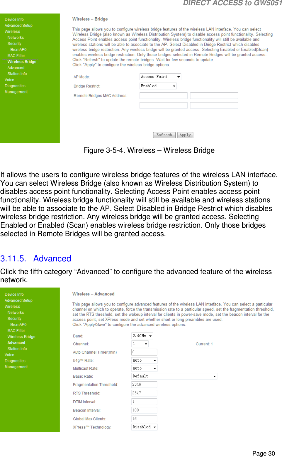
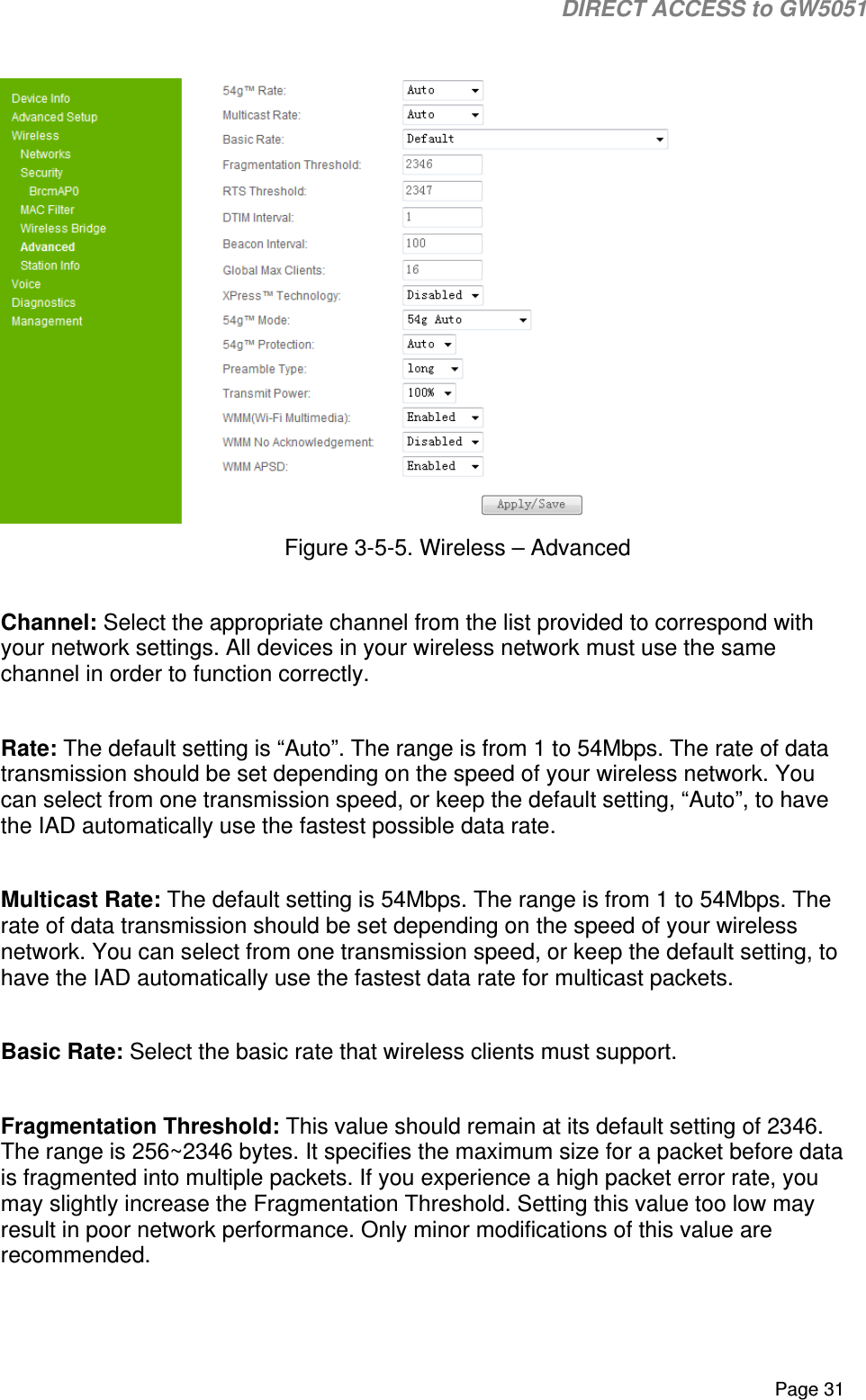
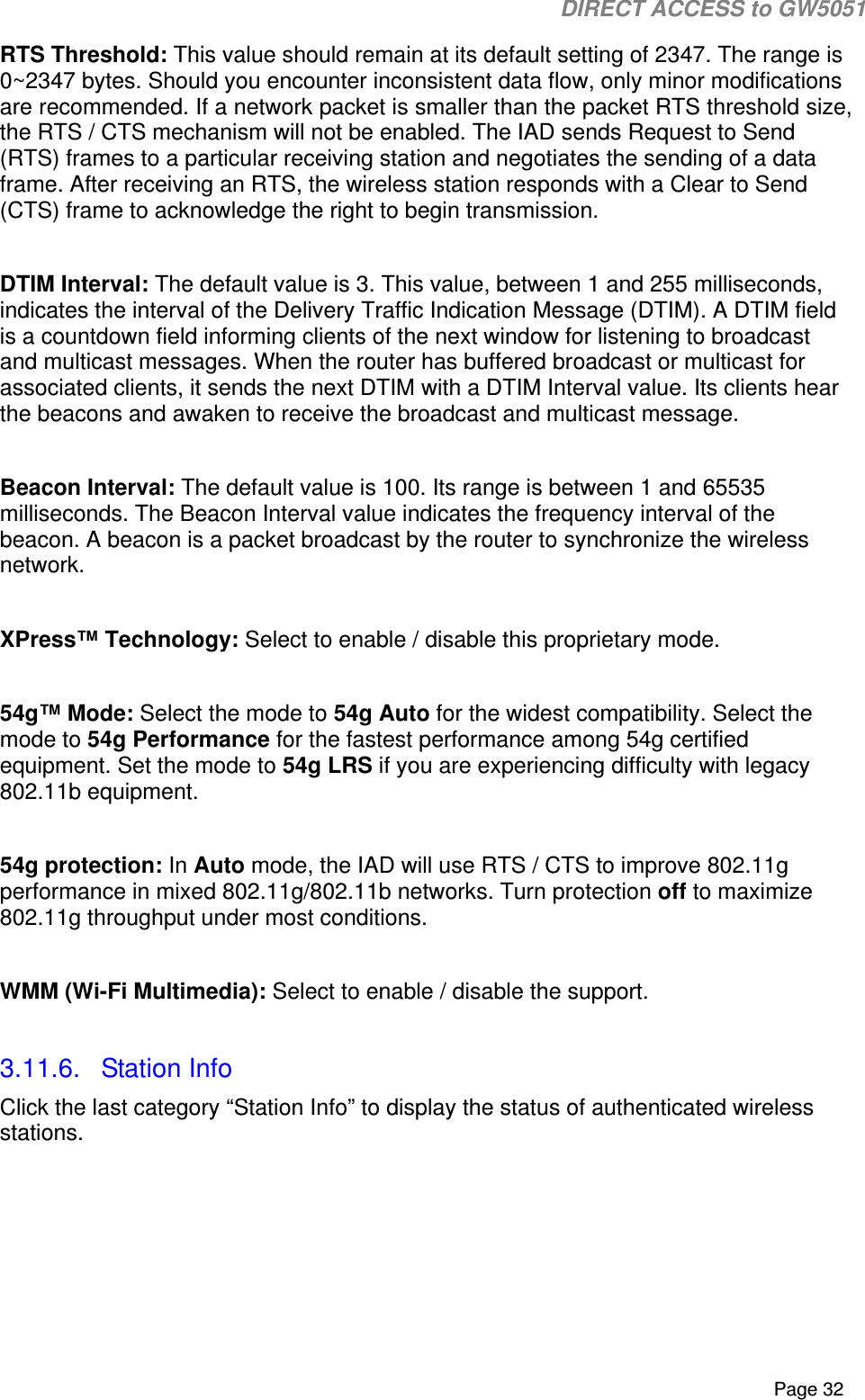

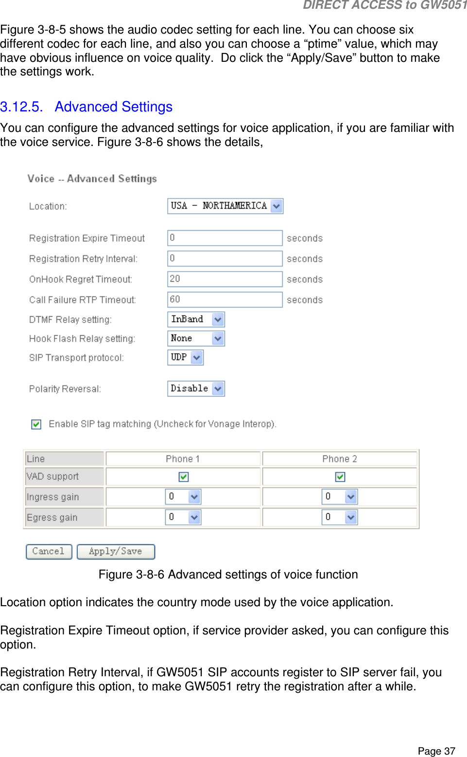
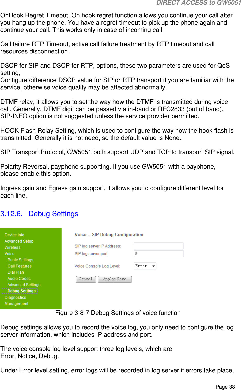
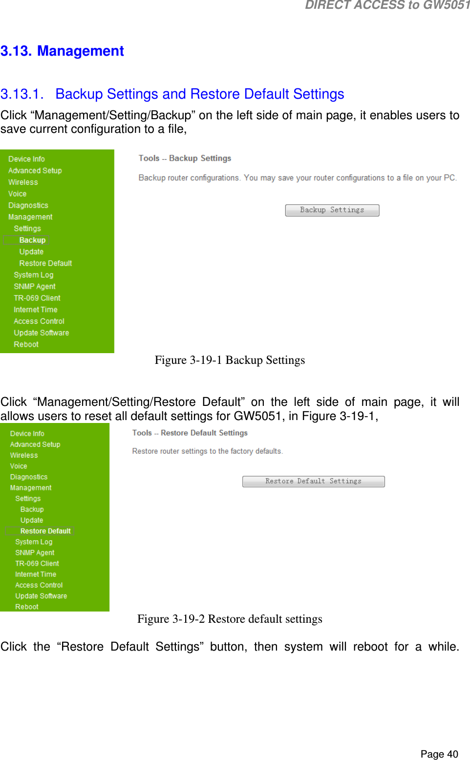
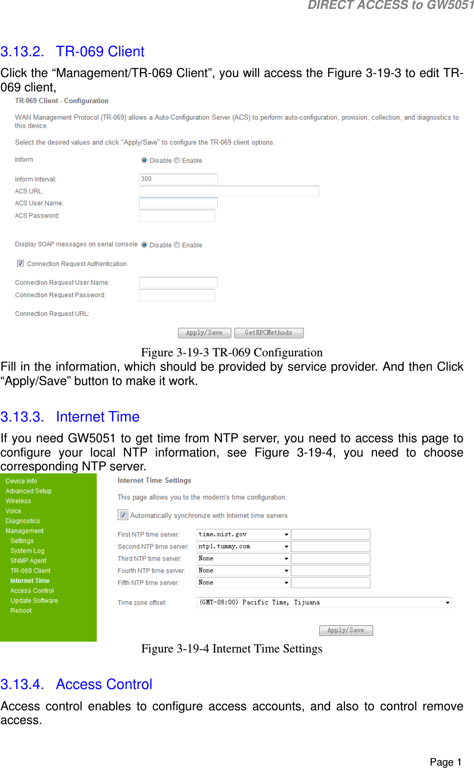
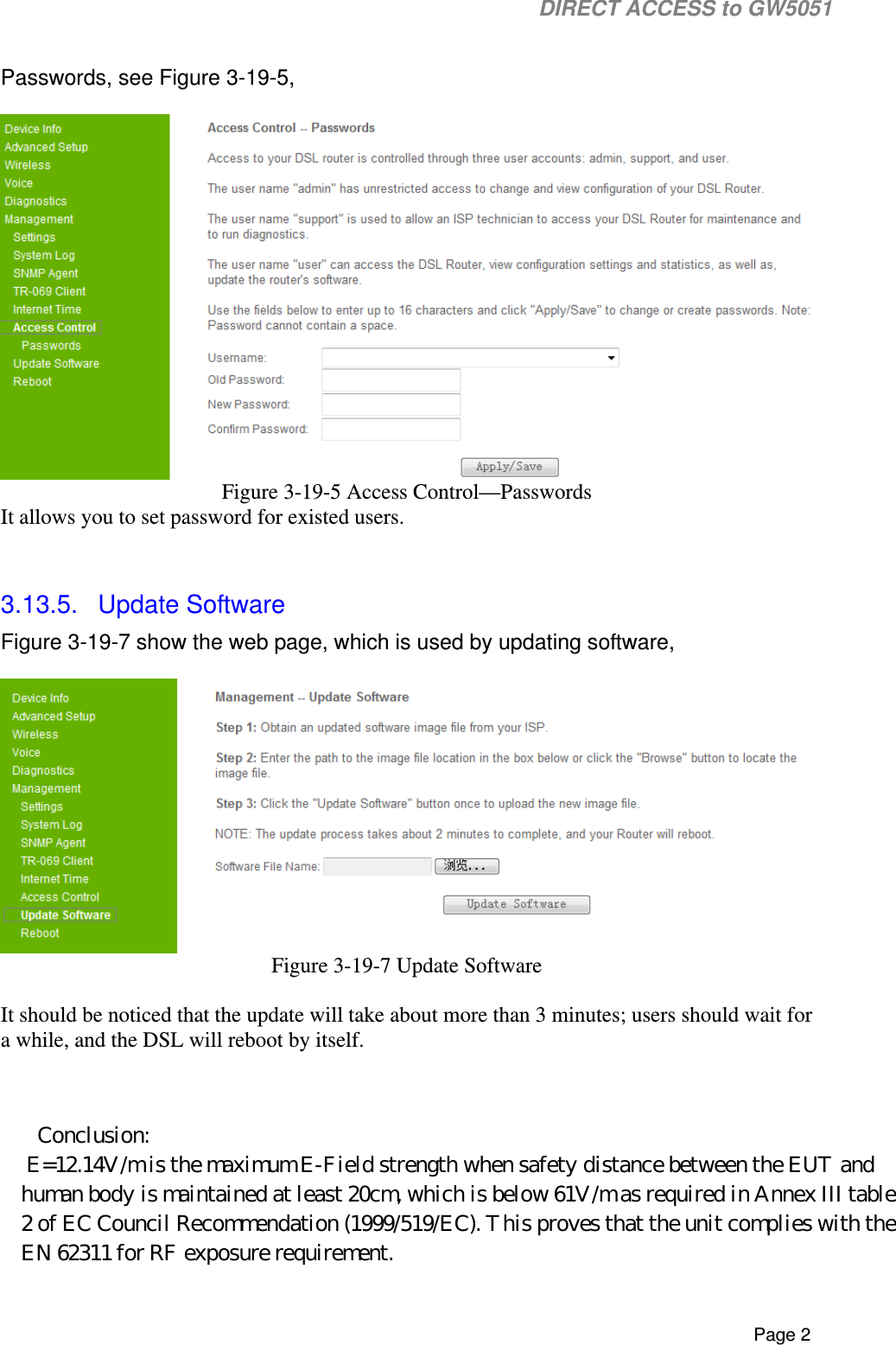
![DIRECT ACCESS to GW5051 Page 36 Figure 3-8-4 Dial plan Configuration of voice function Generally supported dial plan string is like the following, [1-9]xxx|xx+*|xx+#|00x.T|011x.T|x+T However, if you are not sure about settings, keep the dial plan unchanged with default value. 3.12.4. Audio Codec Figure 3-8-5 Audio Codec configuration of voice function](https://usermanual.wiki/Tecom-Co/GW5051/User-Guide-1322886-Page-40.png)