Tecom Co IG7500 Intelligent Gateway User Manual subpart J
Tecom Co Ltd Intelligent Gateway subpart J
Tecom Co >
User Manual

Page 1 of 37
IG7500
Administration Manual
Copyright © 2012 TECOM Co., Ltd.
All Rights Reserved.

IG7500 Administration Manual
Page 2 of 37
Environment
The equipment you have purchased must not be disposed of with household waste. You
should return these to your distributor if they are to replace or dispose of them in an
approved recycling centre.
FCC Statement
This equipment generates, uses, and can radiate radio frequency energy and, if not
installed and used in accordance with the instructions in this manual, may cause
interference to radio communications. This equipment has been tested and found to
comply with the limits for a Class B computing device pursuant to Part 15 of FCC rules,
which are designed to provide reasonable protection against radio interference when
operated in a commercial environment. Operation of this equipment in a residential area is
likely to cause interference, in which case the user, at is own expense, will be required to
take whatever measures are necessary to correct the interface.
CE Declaration of Conformity
This equipment complies with the requirements relating to electromagnetic compatibility,
EN55022 class B for ITE and EN 50082-1. This meets the essential protection
requirements of the European Council Directive 89/336/EEC on the approximation of the
laws of the Member States relating to electromagnetic compatibility.
Copyright Notice
All rights reserved. No part of this publication may be reproduced, transmitted, transcribed,
stored in retrieval system or translated in to any language or computer language, in any
form or by any means, electronic, mechanical, magnetic, optical, chemical, manual, or
otherwise, without the prior written permission of Company.
Company reserves the right to revise the publication and make changes from time to time
in the contents hereof without obligation of this company to notify person of such revision
or changes. The material contained herein is supplied without representation or warranty
of any kind. The Company therefore assumes no responsibility and shall have no liability of
any kind arising from the supply or use of this document or the material contained herein.
Trademarks
Windows 98/NT/2000/XP/7™ and Internet Explorer™ are registered trademarks of
Microsoft Corporation. All other company, brand and product names, like Netscape
Navigator™ are trademarks or registered trademarks of their respective owners.
ISO-9001ISO-9001

IG7500 Administration Manual
Page 3 of 37
WARNING!
1. Read these installation instructions carefully before connecting the equipment to its
power adapter.
2. To reduce the risk of electric shock, do not remove the cover from the equipment or
attempt to dismantle it. Opening or removing covers may expose you to dangerous
voltage levels. Equally, incorrect reassembly could cause electric shock on re-use of
the appliance.
3. Do not expose the equipment to fire, direct sunlight or excessive heat.
4. Do not expose the equipment to rain or moisture and do not allow it to come into
contact with water.
5. Do not install the equipment in an environment likely to present a Threat of Impact.
6. You may clean the equipement using a fine damp cloth. Never use solvents (such as
trichloroethylene or acetone), which may damage the equipement’s plastic surface.
Never spray the equipment with any cleaning product whatsoever.
7. The equipment is designed to work in temperatures from 0oC to 45oC (32oF to 104oF).
8. The equipment must be installed at least 1 meter from radio frequency equipment,
such as TVs, radios, hi-fi or video equipments (which radiate electromagnetic fields).
9. Do not connect the LAN/WAN port to any network other than an Ethernet network.
10. Do not attempt to upgrade your equipment in an unstable power environment. This
could cause unexpected damages.
11. Do not work on the system during lightning storms. Please disconnect all cables.
12. Children don't recognize the risks of electrical appliances. Therefore use or keep the
equipment only under supervision of adults or out of the reach from children.
13. No repair can by performed by the end user, if you experience trouble with this
equipment, for repair or warranty information, please contact your supplier.
Electrical Powering:
The IG7500 can be powered with correct power adaptor, the power adaptor must be
12V/1.5A. Any damage caused to the IG7500 as a result of using unsupported power
adaptors will not be covered by the manufacturer’s warranty.
Product Disposal Warning:
Ultimate disposal of this product, accessories, packing, especially the batteries should be
handled carefully for recycle and nature protection in accordance with national laws and
regulations.
!

IG7500 Administration Manual
Page 4 of 37
Table Of Contents
1. Introduction.................................................................................................................................... 6
2. Getting to Know the IG7500........................................................................................................... 7
2.1 Front Panel................................................................................................................................. 7
2.2 Rear Panel.................................................................................................................................. 8
3. General Features........................................................................................................................... 9
3.1. FXS Application.............................................................................................................. 9
3.1.1 Make an outbound call........................................................................................................ 9
3.1.2 Receive an inbound call ...................................................................................................... 9
3.1.3 Fax/Modem....................................................................................................................... 9
3.1.4 Flash – Analog Port (SLT) Flash Recognition........................................................................ 9
3.2. FXO Application ............................................................................................................. 9
3.2.1 Receive a call from FXO IP line ................................................................................ 9
3.2.2 Receive a call from PSTN line................................................................................... 9
3.2.3 Call Abandon .........................................................................................................10
3.3. System Management.......................................................................................................10
3.3.1 Access Control for Web Page..............................................................................................10
3.3.2 Default Set.......................................................................................................................10
3.3.3 System Time & Date.........................................................................................................10
3.3.4 Auto Provisioning .............................................................................................................10
3.4. Voice Features................................................................................................................10
3.4.1 Caller ID Detection/Generation...........................................................................................10
3.4.2 PSTN Backup...................................................................................................................11
4. Configuration..................................................................................................................................12
4.1 Setup........................................................................................................................................12
4.2 Establish the Connection.............................................................................................................12
4.3 Device Info................................................................................................................................14
4.3.1 Summary.........................................................................................................................14
4.3.2 Statistics..........................................................................................................................14
4.3.3 Route..............................................................................................................................15
4.3.4 ARP ................................................................................................................................15
4.3.5 DHCP .............................................................................................................................16
4.4 Advanced Setup..........................................................................................................................17
4.4.1 LAN................................................................................................................................17
4.4.2 WAN ...............................................................................................................................17
4.4.3 NAT ................................................................................................................................18
4.4.4 Quality of Service.............................................................................................................19
4.4.4.1 DSCP Marking...............................................................................................................19
4.4.4.2 Bandwidth Control.........................................................................................................20
4.4.5 Dynamic DNS..................................................................................................................20
4.5 Wireless ....................................................................................................................................23
4.5.1 Basic ...............................................................................................................................23
4.5.2 Security...........................................................................................................................23
4.5.3 Advanced.........................................................................................................................24
4.6 Voice.........................................................................................................................................26
4.6.1 Extension.........................................................................................................................26
4.6.2 Transmission....................................................................................................................27
4.7 Management..............................................................................................................................30
4.7.1 Settings ...........................................................................................................................30
4.7.2 Access Control.................................................................................................................31
4.7.3 System Log......................................................................................................................32
4.7.4 Time Setting.....................................................................................................................32
4.7.5 Update Software...............................................................................................................33
4.7.6 Reboot.............................................................................................................................33

IG7500 Administration Manual
Page 5 of 37
4.8 Diagnostics................................................................................................................................34
4.9 Logout......................................................................................................................................34
Appendix 1: Product Summary.............................................................................................................35
IG7500 Administration Manual
Page 6 of 37
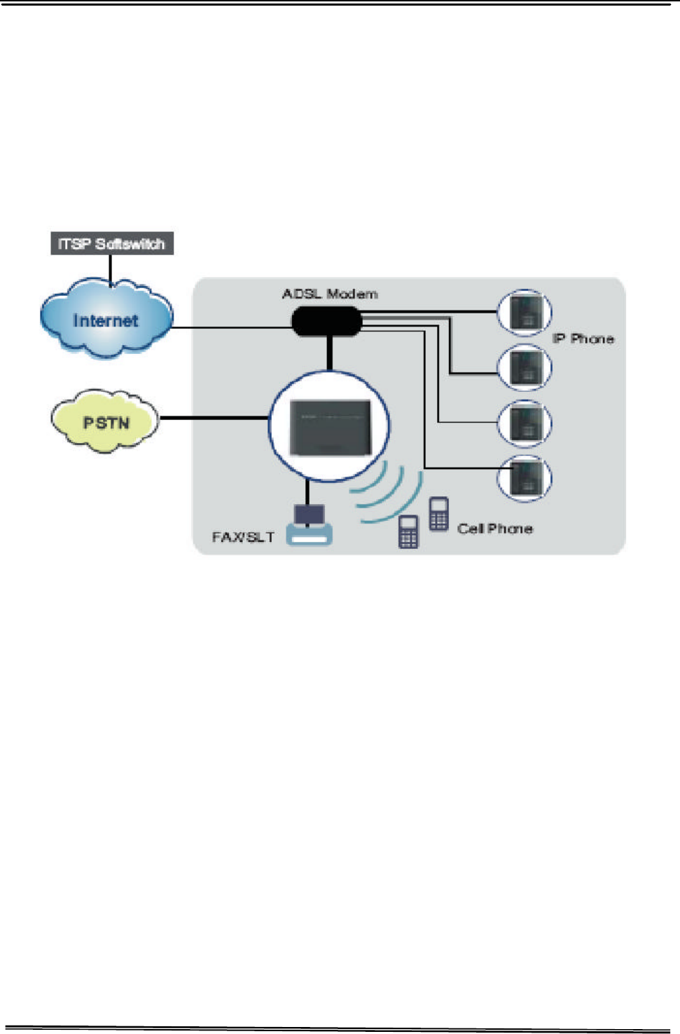
1. Introduction
The IG7500 Gateway supports a FXS port and a FXO port, both have a separate SIP account
assigned to register to remote SIP Sever. The IG7500 also support IP networking systems.
The IG7500 design is designed for hosted IP providers that want to provide fax services,
support PSTN failover, and managed WLAN for the customers.
Interfaces
u 1 FXO port (Loop Start, for PSTN)
u 1 FXS port (for Analog Telephone or FAX)
u 1 WAN port: 10BASE-T/100BASE-TX/1000BASE-T Gigabit Ethernet port
u 4 LAN ports: 10BASE-T/100BASE-TX
u 802.11b/g/n WiFi access point
u 3 USB 2.0 host ports: Connects to your USB storage devices, USB printer or
3G dongle.
Basically, the Maul is required to do the following things:
(1) To understand the architecture, resources, and devices of whole environment
which will be involved with the VoIP communications.
(2) To build a common setting file.
(3) To configure each interfaces and install them.
(4) And to solve the problems that users encounter during operation.
IG7500 Administration Manual
Page 7 of 37
2. Getting to Know the IG7500
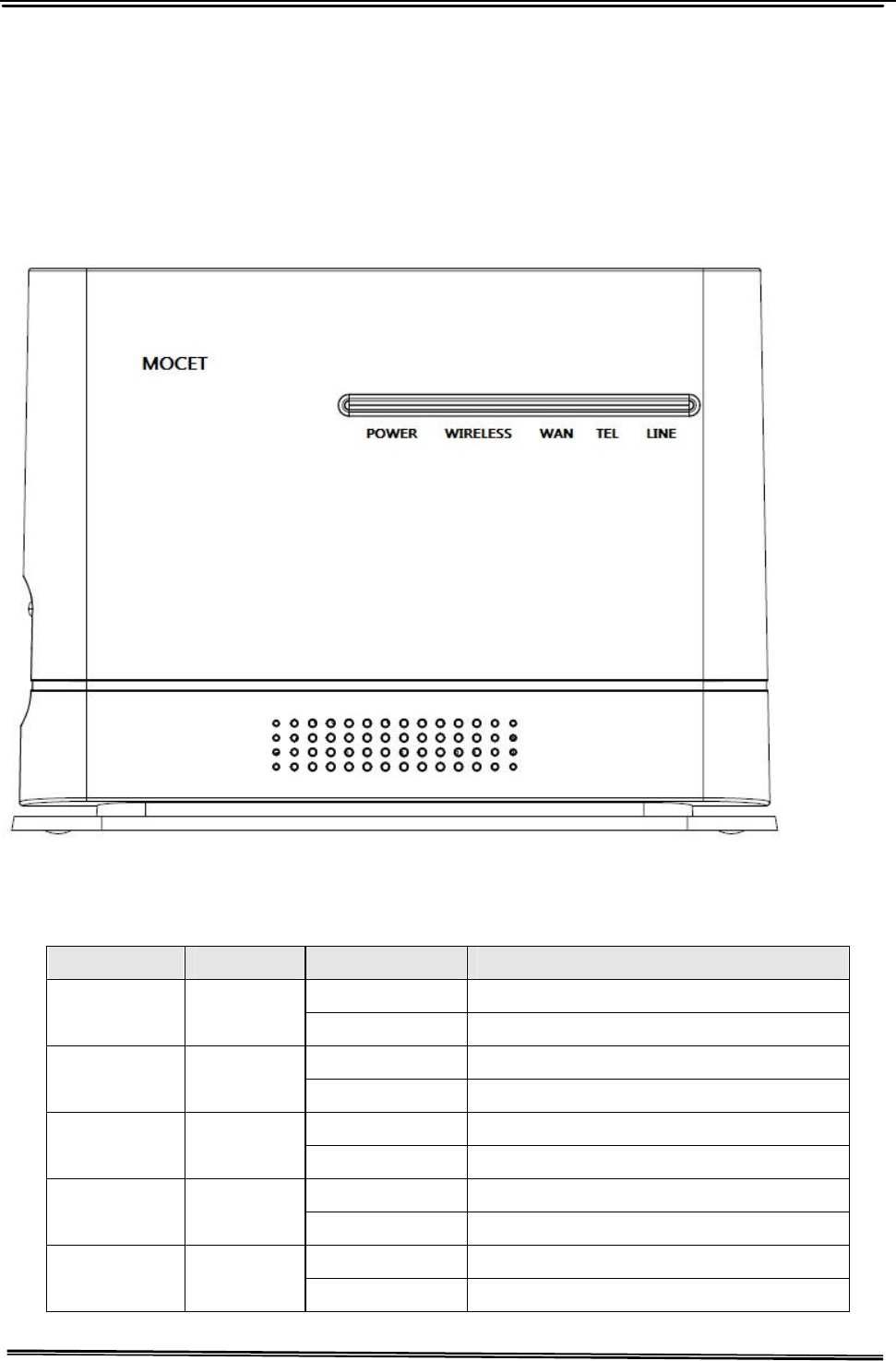
2.1 Front Panel
The front panel contains several LEDs that indicate the status of the IG7500.
Figure 2-1. Front Panel of IG7500
LED Name Color Status Description
On Power On POWER Blue
Off Power off
On Wireless LAN is active WIRELESS Blue
Off Wireless LAN is idle
On Wireless LAN is active WAN Blue
Off Wireless LAN is idle
Off Phone is idle TEL Blue
On Phone is active
Off PSTN Line is idle LINE Blue
On PSTN Line is active
IG7500 Administration Manual
Page 8 of 37
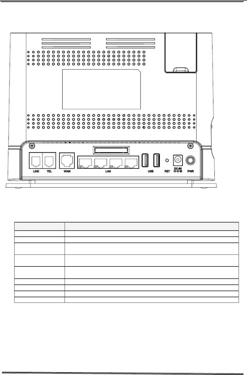
2.2 Rear Panel
The rear panel contains the ports for the IG7500's data and power connections.
Figure 2-2. Rear Panel of IG7500
Label Function
Line RJ-11 connector: Connects the device to your PSTN lines.
TEL RJ-11 connector: Connects the device to your analog phone.
WAN RJ-45 connector: Connects the device to your cable modem, or to your
ADSL Modem. It’s to connect to the remote network.
LAN 4 RJ-45 connector: Connects the device to your PC's Ethernet port, or to
the uplink port on your LAN's hub.
USB 2 USB ports Connects to your USB storage devices, USB printer or 3G
dongle
RST Reset button.
DC-IN Connects to the supplied power converter cable.
USB Connects to your USB storage devices, USB printer or 3G dongle
Power Power On/Off button

IG7500 Administration Manual
Page 9 of 37
3. General Features
(Some enhanced features as described will be added soon.)
3.1. FXS Application
It needs to program the FXS IP account in Web (Voice – Extension), and get the
registration well first.
3.1.1 Make an outbound call
Dial a phone number. When dialing the pound (#”) key or waiting Interdigit Timeout
(programmed in “Web – Voice – Transmission; Default: 5 seconds), the FXS IP call is
formed.
If the FXS IP line fails to register the SIP server:
- If no PSTN line is connected to FXO port, it provides Congestion Tone to FXS when
the FXS goes off-hook.
- If the PSTN line is in use, it provides Congestion Tone to FXS when the FXS goes
off-hook.
- If the PSTN line is idle, the call will be made through the PSTN line..
3.1.2 Receive an inbound call
When getting the inbound call from the FXS IP line, it rings the FXS phone immediately.
The call is formed when the FXS phone answers the call.
3.1.3 Fax/Modem
IG7500 supports FAX/modem tone detection and auto-fallback to G.711. IG7500 also
support to use T.38.
3.1.4 Flash – Analog Port (SLT) Flash Recognition
Flash is the momentary operation of the hook-switch at the analog device, which can be
deciphered in such a way that the previous call in progress is held, or placed in a status
of transfer awaiting further instructions from the user.
3.2. FXO Application
It needs to program the FXO IP account in Web (Voice – Extension), and get the
registration well first.
3.2.1 Receive a call from FXO IP line
If the PSTN line doesn’t exist, the call will be rejected immediately.
If the PSTN line exists, the call between PSTN line and IP line is formed immediately.
When the caller on the IP line hears the PSTN dial tone, dials a phone number to form
the PSTN call.
3.2.2 Receive a call from PSTN line
If the FXO IP account registers well, IG7500 makes the IP call to the specified phone

IG7500 Administration Manual
- 10 -
number (programmed in “Web – Voice – Extension à FXO) through the IP line
immediately.
If the FXO IP account is at Fail state, and the FXS is at idle state, the PSTN line will ring
the FXS phone.
3.2.3 Call Abandon
For PSTN call, IG7500 provides the facility to monitor the call status. If the remote party
hangs up, the ongoing call will be terminated.
The PSTN line monitor is accomplished through monitoring the loop-break signal,
polarity reversal or busy tone. The value range of loop-break signal is:
“Disable”/100/200/…/1000 ms.
3.3. System Management
3.3.1 Access Control for Web Page
IG7500 provides two Access modes for Web Page
- Administrator mode: unrestricted access and program. The mode can be used
from LAN and WAN.
(Default: admin1234/123456)
- Support Mode: allow an ISP technician to maintain and run diagnostics. It can be
used from WAN only.
(Default: support/support)
3.3.2 Default Set
Clear all settings and return the IG7500 set to the factory condition.
3.3.3 System Time & Date
The IG7500 system provides a built-in time clock to track System Time. This clock has
the ability to automatically adjust with network NTP server through internet.
3.3.4 Auto Provisioning
WAN Management Protocol (TR-069) allows an Auto-Configuration Server (ACS) to
perform auto-configuration, provision, collection, and diagnostics to this device.
Firmware upgrade or vendor configuration file backup can be done remotely on ACS
server. Select the desired values and click "Save Settings" to configure the TR-069
client options.
IG7500 also provides an Auto Provision Server (APS) to update IG7500 FW and
Update / Retrieve IG7500 Configuration.
3.4. Voice Features
3.4.1 Caller ID Detection/Generation
IG7500 provides the ability to detect the calling party identification provided by CO via
PSTN lines or by Uplink Server via IP lines.

IG7500 Administration Manual
- 11 -
IG7500 also provide Caller ID Generation to the Caller ID equipped Single Line
Telephone.
3.4.2 PSTN Backup
In case of power failure, IG7500 automatically switches the first PSTN line to the
Single-line analog phone.
IG7500 Administration Manual
- 12 -
4. Configuration
(Some enhanced configuration items as described will be added soon.)
4.1 Setup
l Connect the IG7500 to PC.
l The default LAN IP of the IG7500 is 192.168.1.1.
l The default WAN IP of the IG7500 depends on upper router’s DHCP server.
l For web login, the default user name is “admin1234”, the default password is
“123456”.
l For telnet login, the name/password is the same as web login.
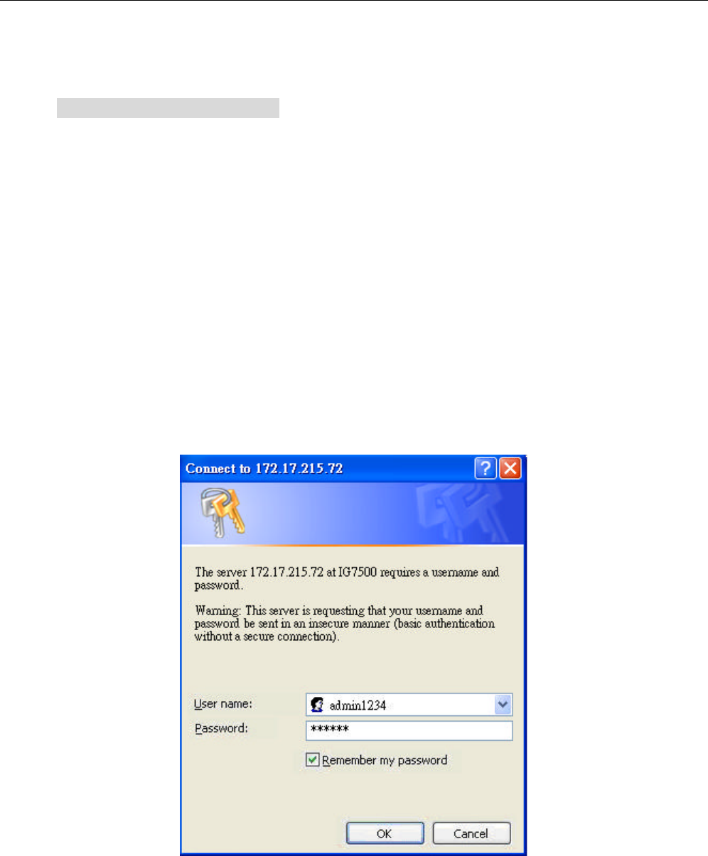
4.2 Establish the Connection
Enter the IP address of IG7500 from the Web Browser.
A Dialogue Box will pop up to request the user to enter username and password. (Figure
4-1)
Figure 4-1. Authentication
Please enter the management username/password into the fields then click the OK button
(default username/password is admin1234/123456).
When the authentication is OK, the home page “Device Info – Summary” will be displayed.
In the Web Configuration, it is divided into eight categories (Figure 4-2):
l Device Info
l Advanced Setup
IG7500 Administration Manual
- 13 -
l Wireless
l Mobile Network
l Voice
l Management
l Diagnostics
l Logout
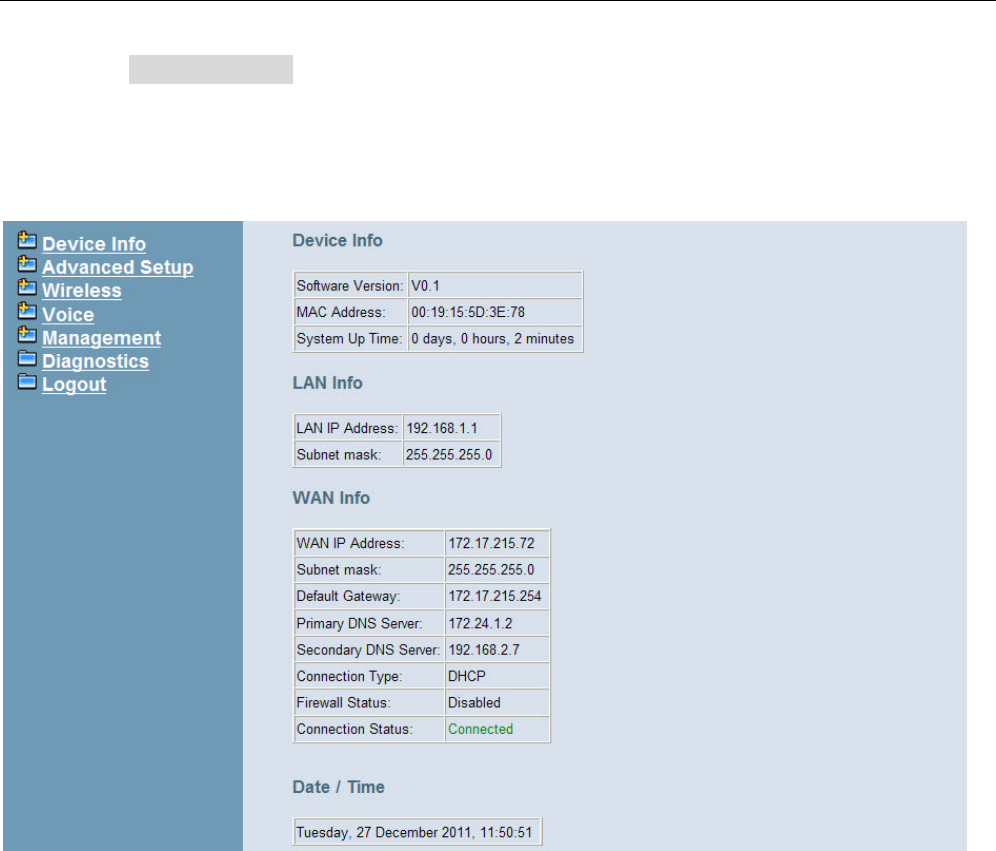
Figure 4-2. Device Info - Summery
IG7500 Administration Manual
- 14 -
4.3 Device Info
This information reflects the current Status of IG7500 connection. It includes the following
topics:
l Summary
l Statistics
l Route
l ARP
l DHCP
4.3.1 Summary
In the page (Figure 4-2) you can get the information reflects the current software version
and connection status. It includes Device Info, Network Info and Date/Time.
For Network Info, it includes the three parts:
l LAN Info: Ethernet LAN status
l WAN Info: Ethernet WAN status
l Secondary WAN Info: Mobile Network status; shown when it exists.
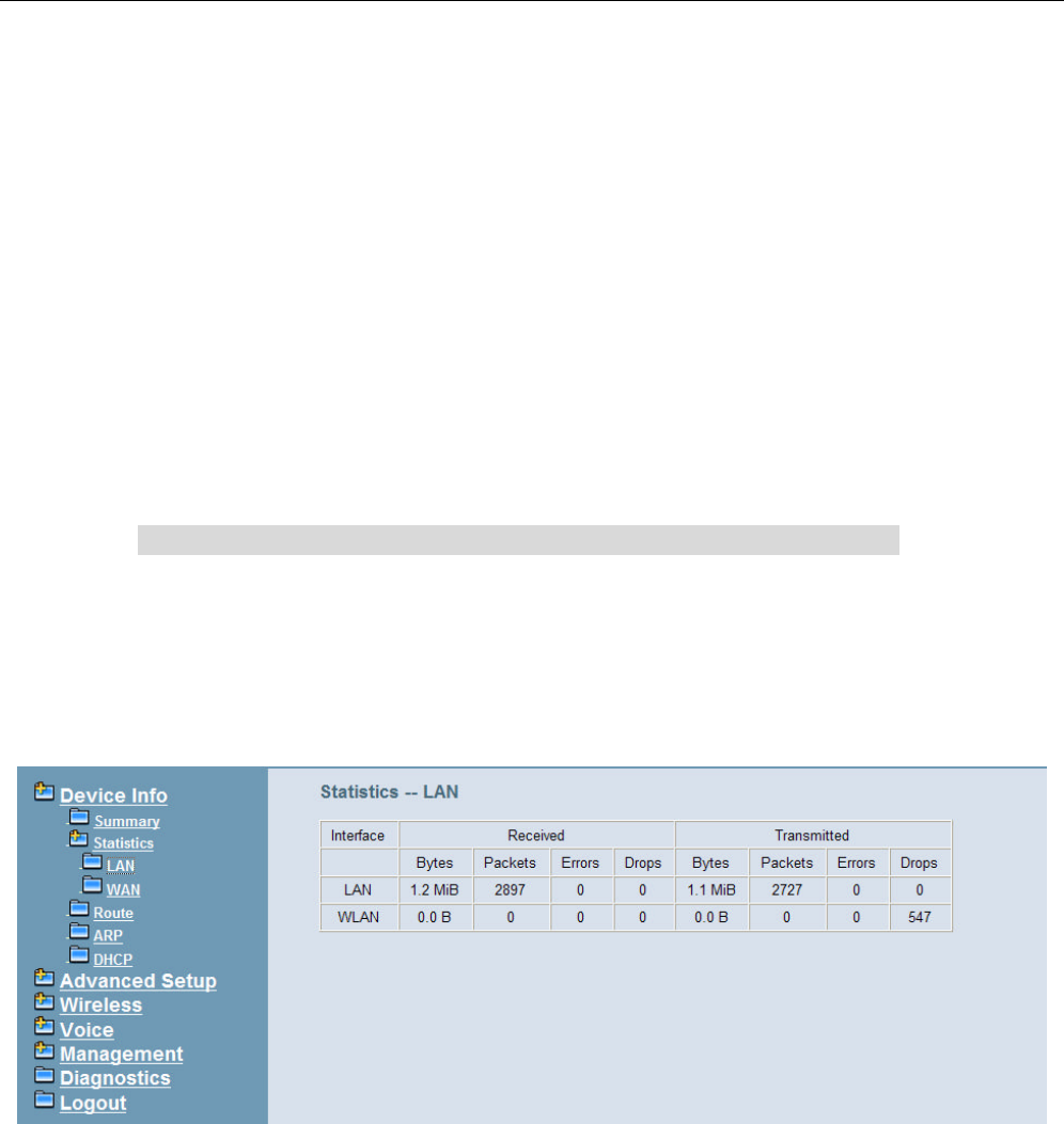
4.3.2 Statistics
It’s separated into two parts: LAN and WAN.
4.3.2.1 LAN
In this page (Figure 4-3) you can get the network statistics of the LAN and Wireless LAN
interface. Click “Reset Statistics” to clean up all network statistics.
Figure 4-3. Device Info – Statistics – LAN
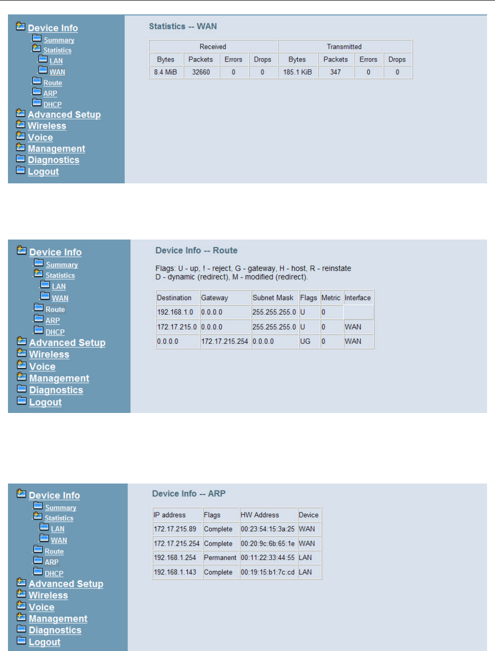
4.3.2.2 WAN
In this page (Figure 4-4) you can get the network statistics of the WAN interface. Click
“Reset Statistics” to clean up all network statistics.
IG7500 Administration Manual
- 15 -
Figure 4-4. Device Info – Statistics – WAN
4.3.3 Route
In this page you can get the IP route information of the device. (Figure 4-5)
Figure 4-5. Device Info – Route
4.3.4 ARP
This page shows an ARP table which maps IP network addresses to hardware addresses
used by data link level protocol. (Figure 4-6)
Figure 4-6. Device Info – ARP
IG7500 Administration Manual
- 16 -
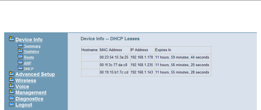
4.3.5 DHCP
This page shows a DHCP Leases table which shows the all used IP addresses under
IG7500’s DHCP Server. (Figure 4-7)
Figure 4-7. Device Info – DHCP
IG7500 Administration Manual
- 17 -
4.4 Advanced Setup
Advanced Setup allows system administrator to configure the following topics:
l WAN
l LAN
l NAT
- Virtual Servers
- DMZ Host
l Quality of Service
- DSCP Marking
- Bandwidth Control
l Dynamic DNS
l File Server
l Print Server
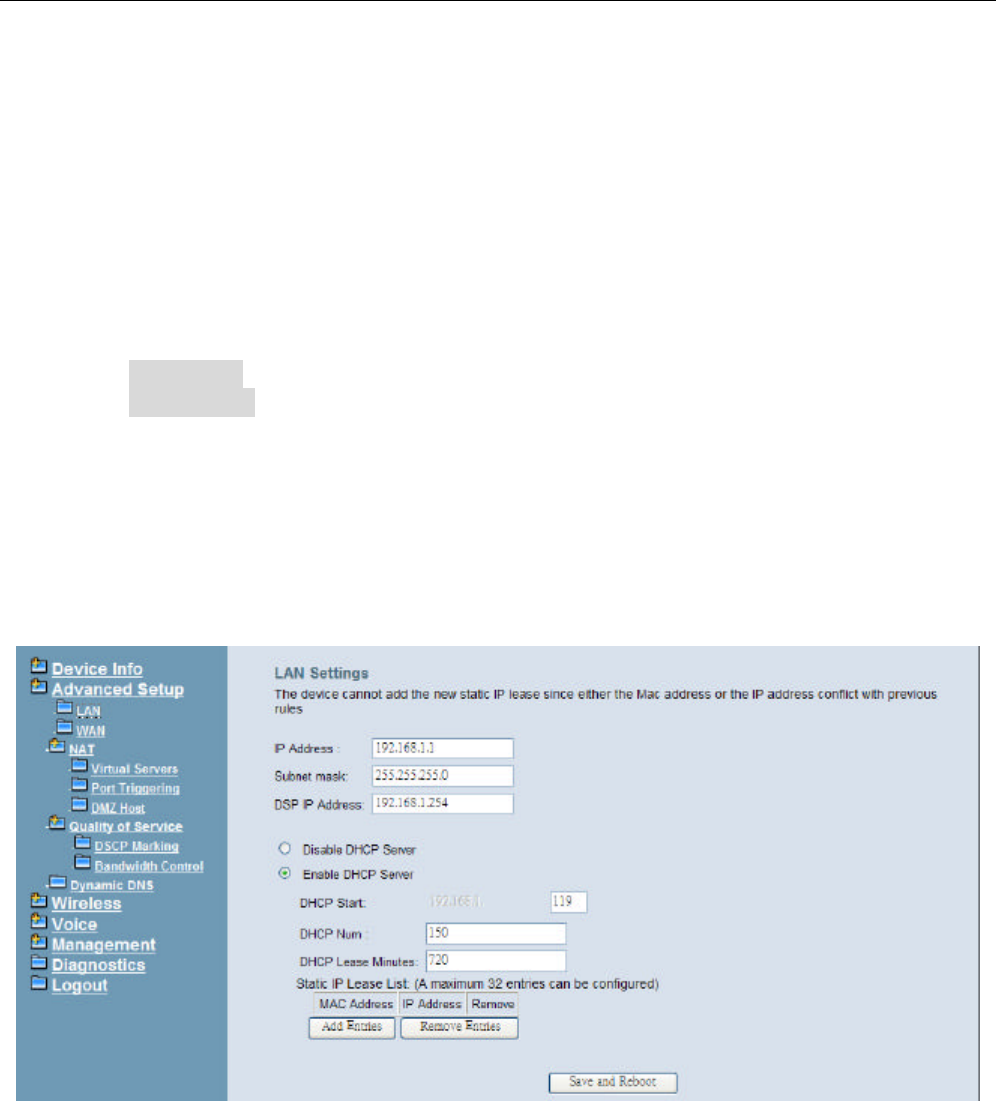
4.4.1 LAN
It allows you to set LAN IP and Subnet Mask for LAN interface. A DSP IP address can be
configured for FXO/FXS application. You can also enable or disable DHCP Server and
configure related settings. The “Static IP Lease List” allows to program 32 entries to have
the fixed IP address for the specified devices. If needed, it can also configure the second
IP address and Subnet Mask for the LAN interface (Figure 4-8).
Figure 4-8. Advanced – LAN
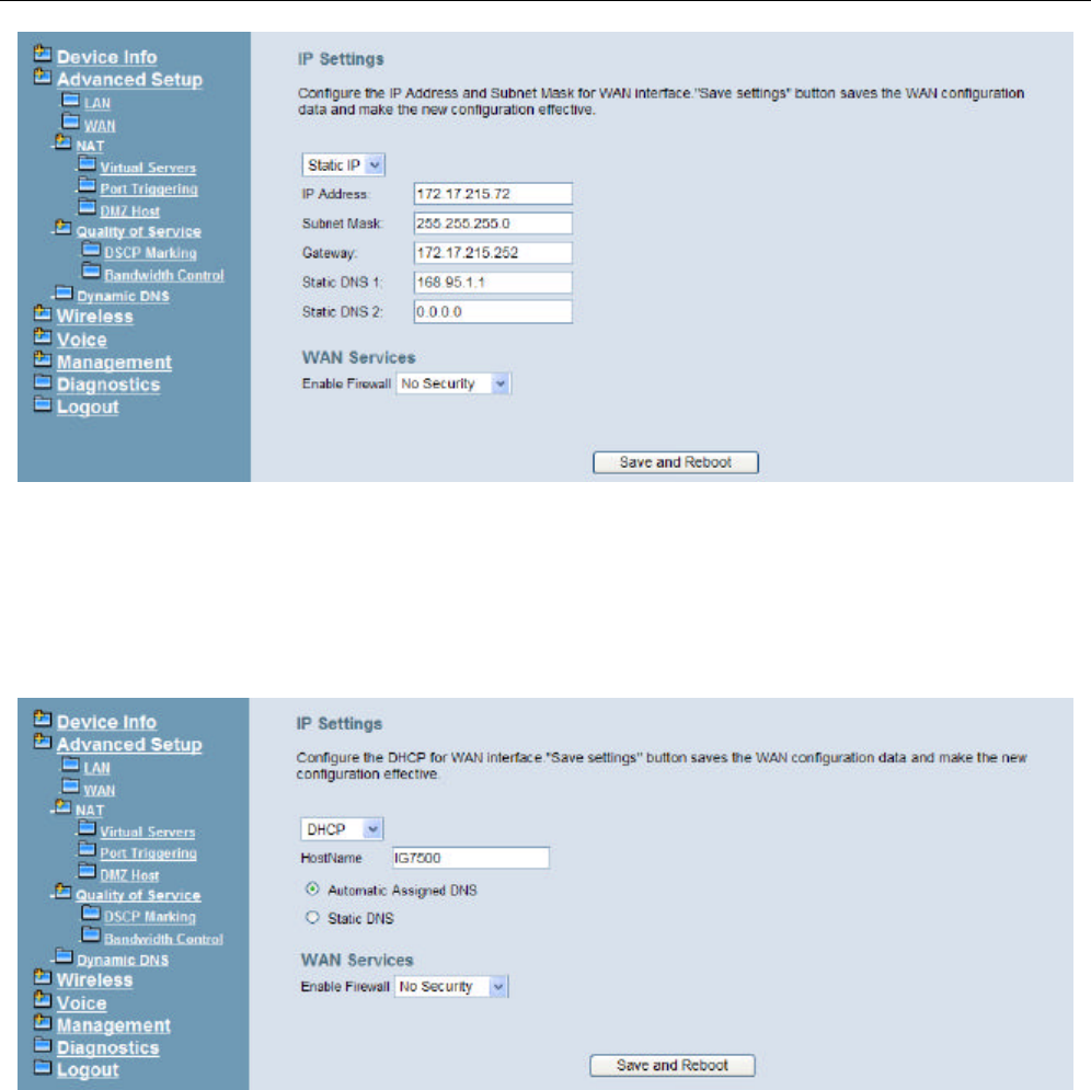
4.4.2 WAN
There are two modes that you can give WAN IP address to IG7500: Static IP mode and
DHCP mode. You can also enable or disable Firewall.
Network Address Translation (NAT) allows you to share one public WAN IP address for
multiple computers on your LAN side. In IG7500, NAT is default enabled and is not shown
on the page to prevent it from being disabled.
This page shows the setting of WAN interface which is Static IP mode (Figure 4-9).
IG7500 Administration Manual
- 18 -
Figure 4-9. Advanced – WAN (Static IP Mode)
The Dynamic Host Configuration Protocol (DHCP) is an Internet protocol for automating
the configuration of computers that use TCP/IP. DHCP can be used to automatically
assign IP addresses, to deliver TCP/IP stack configuration parameters such as the subnet
mask and default router, and to provide other configuration information.
This page shows the setting of WAN interface which is DHCP mode (Figure 4-10).
Figure 4-10. Advanced – WAN (DHCP Mode)
4.4.3 NAT
It’s separated into two parts: Virtual Servers, and DMZ Host.
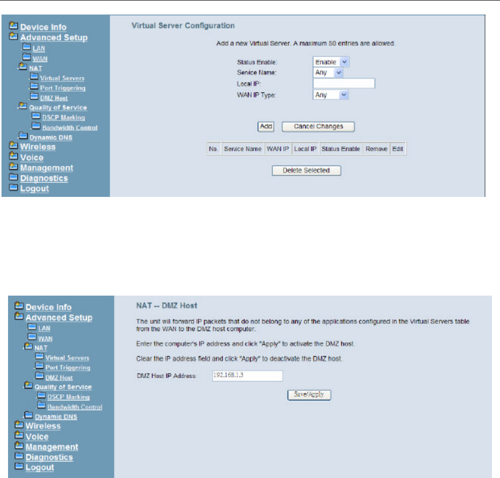
4.4.3.1 Virtual Servers
Virtual Server allows you to direct incoming traffic from WAN side identified by Protocol
and External port to the internal server with private IP address on the LAN side. The
“Internal Port” can be modified if the “External Port” needs to be converted to a different
port number used by the server on the LAN side. The remote IP should be specified in the
table to allow the access. A maximum 50 entries can be configured. (Figure 4-11)
IG7500 Administration Manual
- 19 -
Figure 4-11. Advanced – NAT – Virtual Servers
4.4.3.2 DMZ Host
IG7500 will forward IP packets that do not belong to any of the applications configured in
the Virtual Servers table to the DMZ host computer. Enter the computer's IP address and
click "Save Settings" to activate the DMZ host. Clear the IP address field and click "Save
Settings" to deactivate the DMZ host. (Figure 4-12)
Figure 4-12. Advanced – NAT – DMZ
4.4.4 Quality of Service
It’s separated into two parts: DSCP Marking, and Bandwidth Control
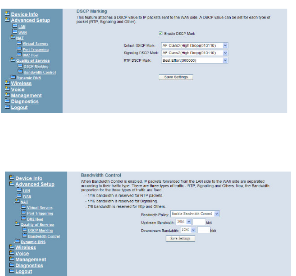
4.4.4.1 DSCP Marking
IP QoS is applied to the traffic from LAN to WAN; the traffic from WAN to LAN will not be
applied.(Figure 4-13)
If "Enable DSCP Mark” checkbox is selected, choose a default DSCP mark to
automatically mark incoming traffic without reference to a particular classifier. Click "Save
Settings" button to save it. Note: If "Enable DSCP Mark” checkbox is not selected, all QoS
will be disabled for all interfaces. The default DSCP mark is used to mark all egress
packets.
IG7500 Administration Manual
- 20 -
Figure 4-13. Advanced – Quality of Service – DSCP Marking
4.4.4.2 Bandwidth Control
Bandwidth Control allows you to control WAN port's upstream bandwidth according to your
settings, and it can ensure the highest priority IP packet traffic throughput. By default, all
voice packets have been queued in the highest IP packets, and the others have been
queued in the normal IP packets if they have not been set in the traffic class rule.
Figure 4-14. Advanced – Quality of Service – Bandwidth Control
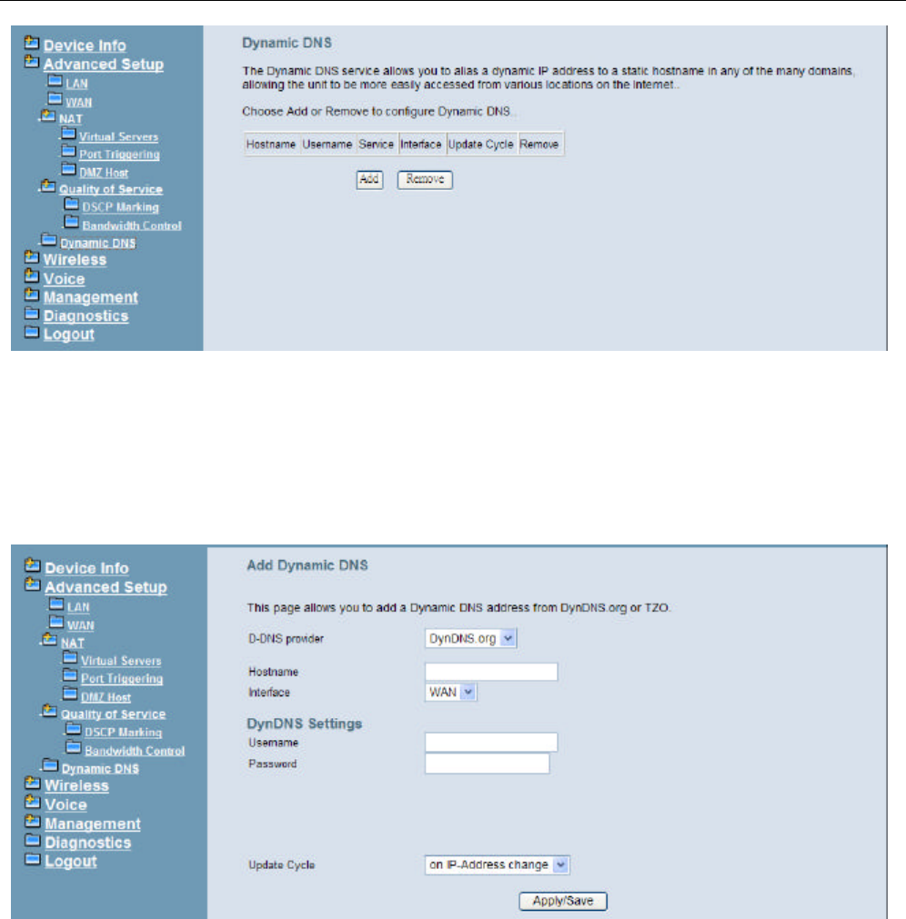
4.4.5 Dynamic DNS
The Dynamic DNS service allows you to alias a register domain name to a dynamic IP
address. It allows IG7500 to be more easily accessed from various locations on the
Internet. Click “Add” or “Remove” to configure Dynamic DNS. (Figure 4-15)
IG7500 Administration Manual
- 21 -
Figure 4-15. Advanced – Dynamic DNS
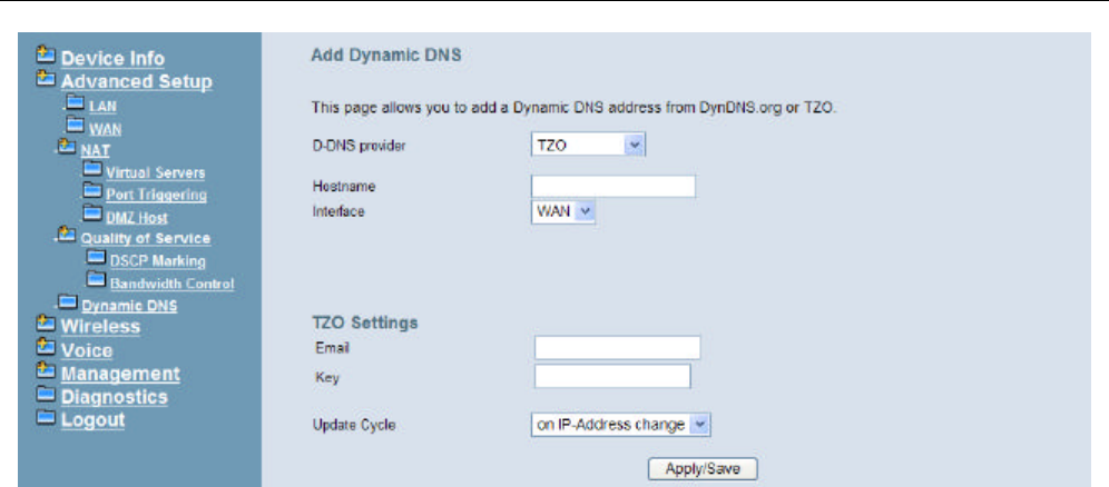
Now IG7500 support for two DDNS provider, DynDNS.org and TZO. Specify the register
hostname and choose the related interface. Fill in the username/password or email/key
and click “Apply/Save”. IG7500 will update the current IP with DDNS provider when click
“Apply/Save” or system reboot successfully. IG7500 will also update the current IP
automatically with DDNS provider in the programmed Update Cycle. (Figure 4-16, Figure
4-17)
Figure 4-16. Advanced – Dynamic DNS – DynDNS.org
IG7500 Administration Manual
- 22 -
Figure 4-17. Advanced – Dynamic DNS – TZO
IG7500 Administration Manual
- 23 -
4.5 Wireless
Use the Wireless screen to configure the IG7500 for wireless access. It is separated into 7
parts:
l Basic
- Primary
l Security
l Advanced
l Station Info
l Power Saving
The configurable items for each part would be described in the following.
4.5.1 Basic
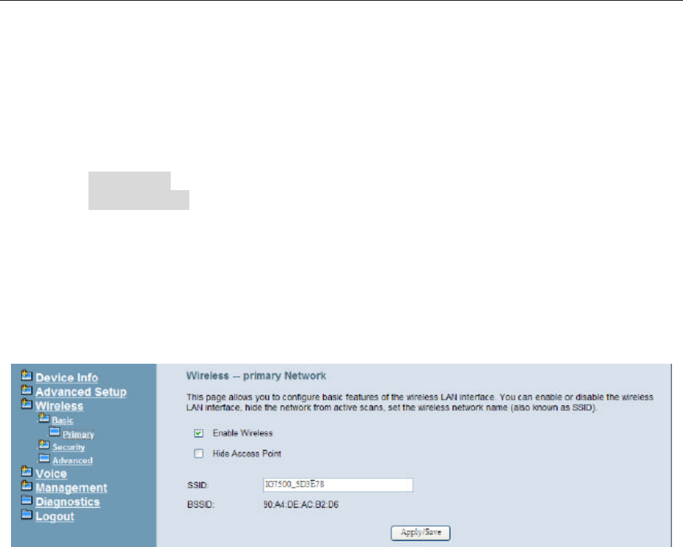
4.5.1.1 Primary
This page allows you to configure the basic features of the wireless LAN interface. You can
enable or disable the wireless LAN interface, and hide the network from active scans.
(Figure 4-18)
Figure 4-18. Wireless – Basic – Primary
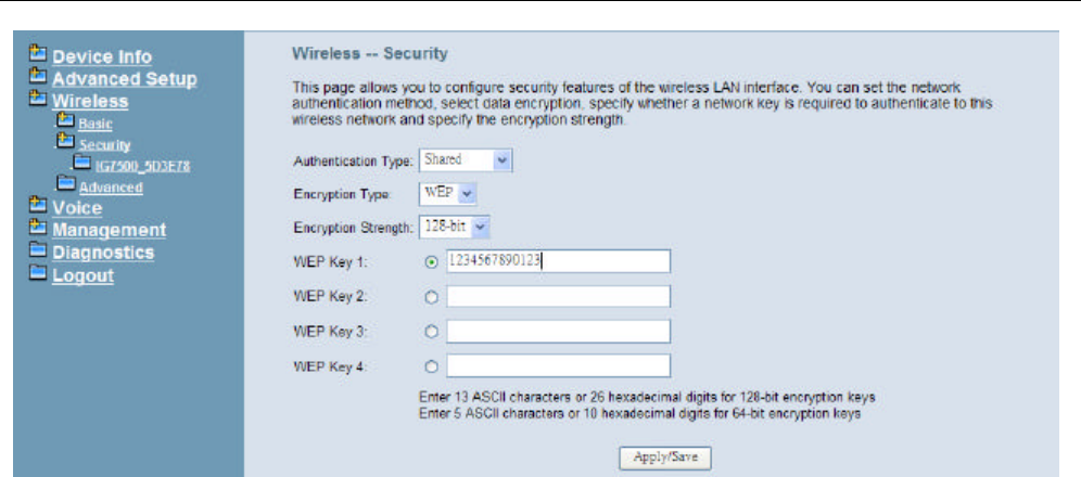
4.5.2 Security
This page allows you to configure security features of the wireless LAN interface. You can
set the network authentication method, selecting data encryption, specify whether a
network key is required to authenticate to this wireless network and specify the encryption
strength. Click "Apply/Save" to configure the wireless security options. (Figure 4-19)
The following items will be configured in the page:
Network Authentication: Set the network Authentication method. Open and Shared
can use the WEP Encryption. WPA-PSK requires a valid WPA Pre-Shared Key to be
set.
WPA/WPA2 Pre-Shared Key: Set the WPA/WPA2 Pre-Shared Key (PSK).
IG7500 Administration Manual
- 24 -
Figure 4-19. Wireless – Security
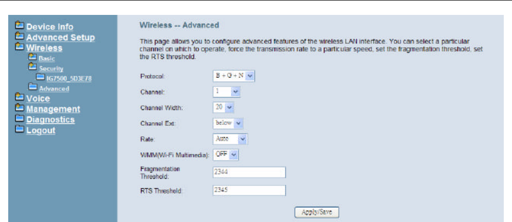
4.5.3 Advanced
It allows you to configure advanced features of the wireless LAN interface. You can select
a particular channel on which to operate, force the transmission rate to a particular speed,
set the fragmentation threshold, set the RTS threshold, set the wakeup interval for clients
in power-save mode, set the beacon interval for the access point, set XPress mode and
set whether short or long preambles are used. Click "Save Settings" to configure the
advanced wireless options. (Figure 4-20)
Protocol:
Channel: Select the appropriate channel from the list provided to correspond with your
network settings. All devices in your wireless network must use the same channel in
order to function correctly.
Channel Width: User can choose 20MHz or 40MHz
Channel Extension: Specify if the extension channel should be in the “below” or
“above” sideband.
Rate: Select the basic rate that wireless clients must support.
WMM (Wi-Fi Multimedia): Feature that improves the experience for audio, video and
voice applications over a Wi-Fi network.
Fragmentation Threshold: This value should remain at its default setting of 2346. The
range is 256~2346 bytes. It specifies the maximum size for a packet before data is
fragmented into multiple packets. If you experience a high packet error rate, you may
slightly increase the Fragmentation Threshold. Setting this value too low may result in
poor network performance. Only minor modifications of this value are recommended.
RTS Threshold: This value should remain at its default setting of 2347. The range is
0~2347 bytes. Should you encounter inconsistent data flow, only minor modifications
are recommended. If a network packet is smaller than the packet RTS threshold size,
the RTS/CTS mechanism will not be enabled. The IAD sends Request of Send (RTS)
frames to a particular receiving station and negotiates the sending of a data frame. After
receiving an RTS, the wireless station responds with a Clear to Send (CTS) frame to
acknowledge the right to begin transmission.
IG7500 Administration Manual
- 25 -
Figure 4-20. Wireless – Advanced
IG7500 Administration Manual
- 26 -
4.6 Voice
Use the Voice screen to configure the IG7500’s voice related parameters. It allows system
administrator to configure the following topics:
l Extension
l Transmission
The configurable items for each part would be described in the following.
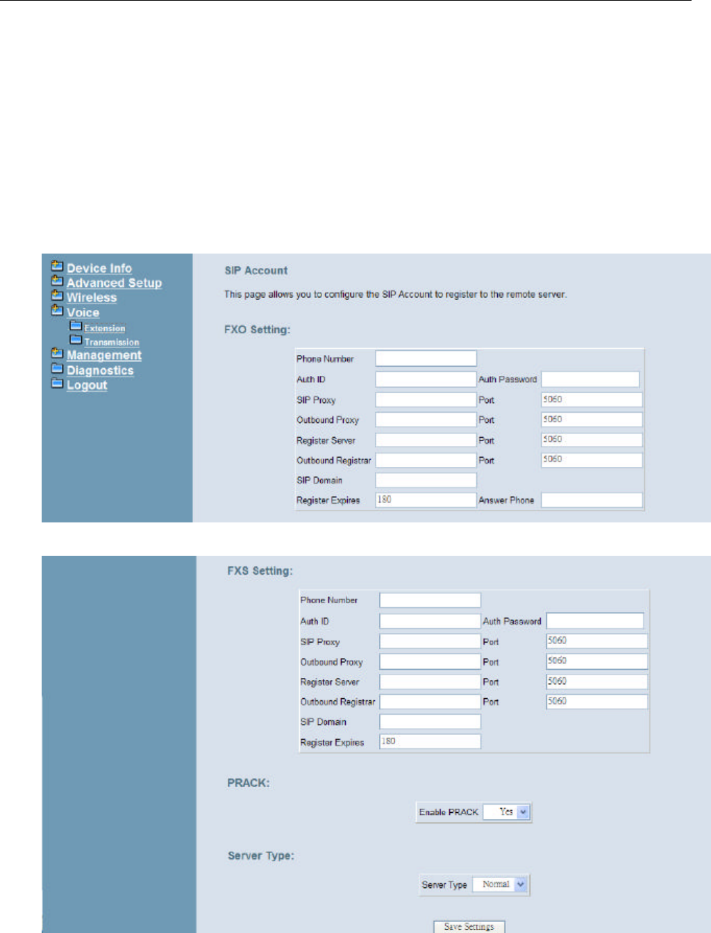
4.6.1 Extension
Use the Extension screen to configure IG7500’s FXS/FXO SIP registration account to
remote Server. (Figure 4-21)
Figure 4-21. Voice –Extension -1
Figure 4-22. Voice – Extension -2

IG7500 Administration Manual
- 27 -
FXO/FXS Settings:
Phone Number: It’s the assigned phone number from uplink server.
Auth ID: The Account ID of registration to uplink server. It’s used for Digest
Authentication.
Auth Password: The Password of registration to uplink server. It’s used for Digest
Authentication.
SIP Proxy: The position of uplink SIP proxy server. IP address and domain name are
all supported.
SIP Proxy Port: The SIP signal port of uplink registrar server.
Outbound Proxy: The address of uplink outbound proxy server. All sip request packet
will be sent to this server that will determine their next hops.
Outbound Proxy Port: The SIP signal port of uplink outbound proxy server.
Register Proxy: The position of uplink register server. IP address and domain name
are all supported.
Register Proxy Port: The SIP signal port of uplink registrar server.
Outbound Registrar: The address of uplink outbound Registrar server. All REGISTER
packets will be sent to this server that will determine their next hops.
Outbound Registrar Port: The SIP signal port of uplink outbound registrar server.
Register Expires: It’s the time for IG7500 sends REGISTER to uplink register server. It
counts based on second.
RPort:
When client is behind a NAT, the rport and received filed can allow SIP proxy to append
the public IP address and port of NAT and transfer SIP message correctly. Choose
“Enable” to use this function.
Server Type:
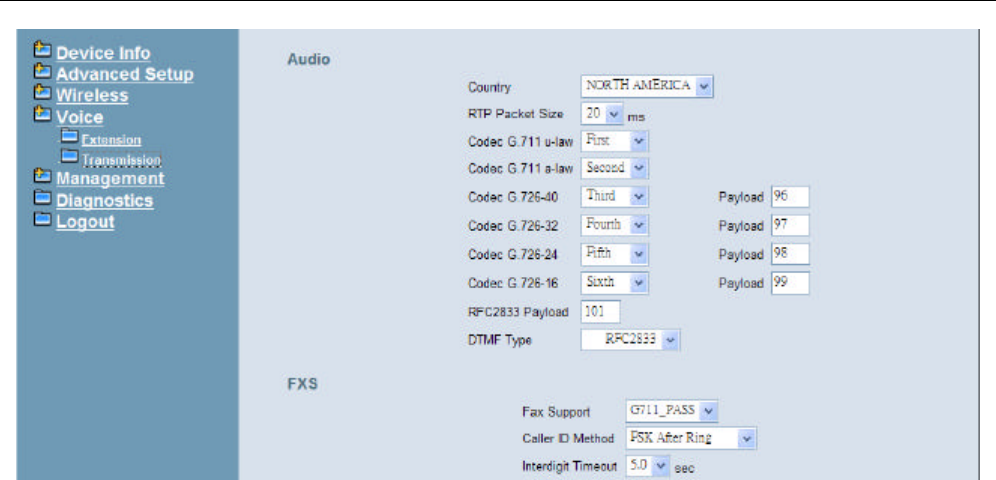
4.6.2 Transmission
This page allows you to configure the Audio, FXS, and FXO settings. Click “Save Settings”
button to save the new configuration. (Figure 4-23)
IG7500 Administration Manual
- 28 -
Figure 4-23. Voice – System – Transmission – 1
Audio: It is used to set many Audio-related options. It will be applied to the all FXS and
PSTN lines.
Country: It may be used to determine not only the Caller ID detection/transmission
method but also ring/tone cadence/frequency.
RTP Packet Size: 10/20/30/40/50/60 ms.
Codec G.711 u-law, G.711 a-law, G.726-16, G.726-24, G.726-32, G.726-40: IG7500
supports different audio priority. You can choose “None”, “First”, “Second”, “Third”,
“Fourth”, “Fifth” and “Sixth”.
RFC2833 Payload: It’s used as the default RFC2833 payload type when making the
outbound calls.
DTMF Type: In IG7500, there are two methods for transmitting DTMF tone. Select
RFC2833 Method, the DTMF tone will be transmitted by event packet. Select SIP-INFO
Method, the DTMF tone will be represent in SIP INFO Message.
FXS: It is used to set many FXS-related options.
Fax Support: The system supports FAX/modem tone detection with G.711 and T38
mode.
Call ID Method: The system provides the ability to detect the calling party identification
provided by PSTN lines. It also transmits the calling party identification to POTS ports.
There are four choices: NONE, DTMF Before Ring, DTMF After Ring, FSK Before Ring,
FSK After Ring.
Inter-digit Timeout: Its range is from 2 to 9 seconds.
IG7500 Administration Manual
- 29 -
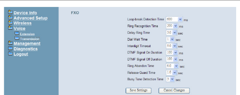
Figure 4-24. Voice – System – Transmission – 2
FXO: It is used to set many central office line options.
Loop Break Detection Time: For every PSTN/FXO call, system provides the facility to
monitor the call status. If the remote party hangs up, the ongoing call must be
terminated. The PSTN line monitor is done by the loop-break signal or busy tone. The
value range is: Disable/100/200/…/1000 ms.
Ring Recognition Time: The timer determines the minimum ring duration recognized
as a valid incoming ring on a FXO port. Shorter ring signals are ignored. The timer
range is 200ms to 600ms in 40ms increments.
Delay Ring Time: The timer is to allow the Central Office to send ICLID before the call
is answered. Once the timer expires, the programmed extensions will ring and the
ICLID number will be sent to the ringing extensions. The timer range is 3 to 6 seconds
on 0.5 second increments.
Dial Wait Time: When the user seizes a PSTN/FXO line, the Stable Time delay is
needed to wait the dial tone from Central Office. The timer range is 0 to 8 seconds on 1
second increments.
Inter-digit Timeout: Its range is from 2 to 9 seconds.
DTMF Signal On/Off Duration: The on/off time duration of DTMF signal. Their ranges
are from 50 to 200 ms.
Ring Abandon Time: It specifies the maximum time between valid ring signals from the
CO/PBX. If the duration between rings exceed the Ring Abandon time, IG7500 stops
ringing the destination(s) and the port returns to idle. The timer range is 1 to 10 seconds
on 1 second increments.
Release Guard Time: The guard time to ignore the noise signal when releasing the call.
The timer range is 1.0 to 3.0 seconds on 0.5 second increments.
Busy Tone Detection Time: System detects the busy tone to monitor the call status.
When it reaches the detection time, system assumes the remote party hangs up. The
ongoing call will be terminated. When setting the time to “0”, the Busy Tone detection
will be disabled.
IG7500 Administration Manual
- 30 -
4.7 Management
The system administrator can do the following functions to manage the configurations,
events, and software update of the IG7500.
l Settings
- Backup
- Update
- Restore Default
l Access Control
- Services
- Password
l System Log
l Time Settings
l Update Software
l Reboot
4.7.1 Settings
The settings area allows the administrator to create a backup, update the system, and
restore the system to factory default.
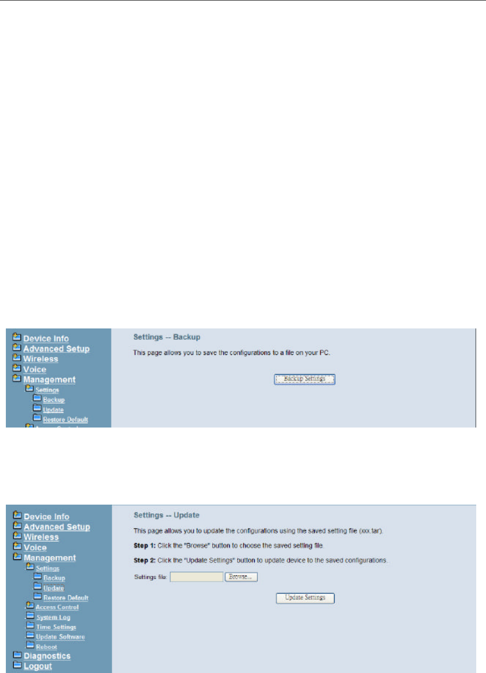
4.7.1.1 Backup
Click “Backup Settings”, you may save your IG7500’s configurations to a file on your PC.
The backup file is a compress file (.tar). It includes the internal System Configuration file,
(Figure 4-25)
Figure 4-25. Management – Settings – Backup
4.7.1.2 Update
Click “Browse” to locate the setting file saved on the Local PC. The file must be a
compress file (.tar). Then, click “Update Settings” would apply the settings to the IG7500
according to the configuration file. (Figure 4-26)
Figure 4-26. Management – Settings – Update
IG7500 Administration Manual
- 31 -
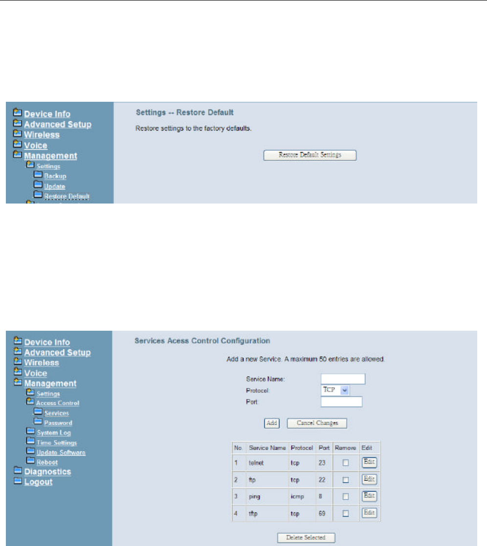
4.7.1.3 Restore Default
Click “Restore Default Settings” to restore the factory default settings. This would be
helpful when the settings mass up. After IG7500 returns to factory default settings, the
wizard setup is invoked automatically when the administrator accesses to IG7500’s web
server. (Figure 4-27)
Figure 4-27. Management – Settings – Restore Default
4.7.2 Access Control
This item allows you to configure some service Ports, enable/disable some services, IP
Address access control, and password for user, support, and administrator.
4.7.2.1 Service
This page allows you to enable the services from being used when “Firewall” (“Advanced
Setup” – WAN” page) is enabled. (Figure 4-28)
Figure 4-28. Management – Access Control –Service Port
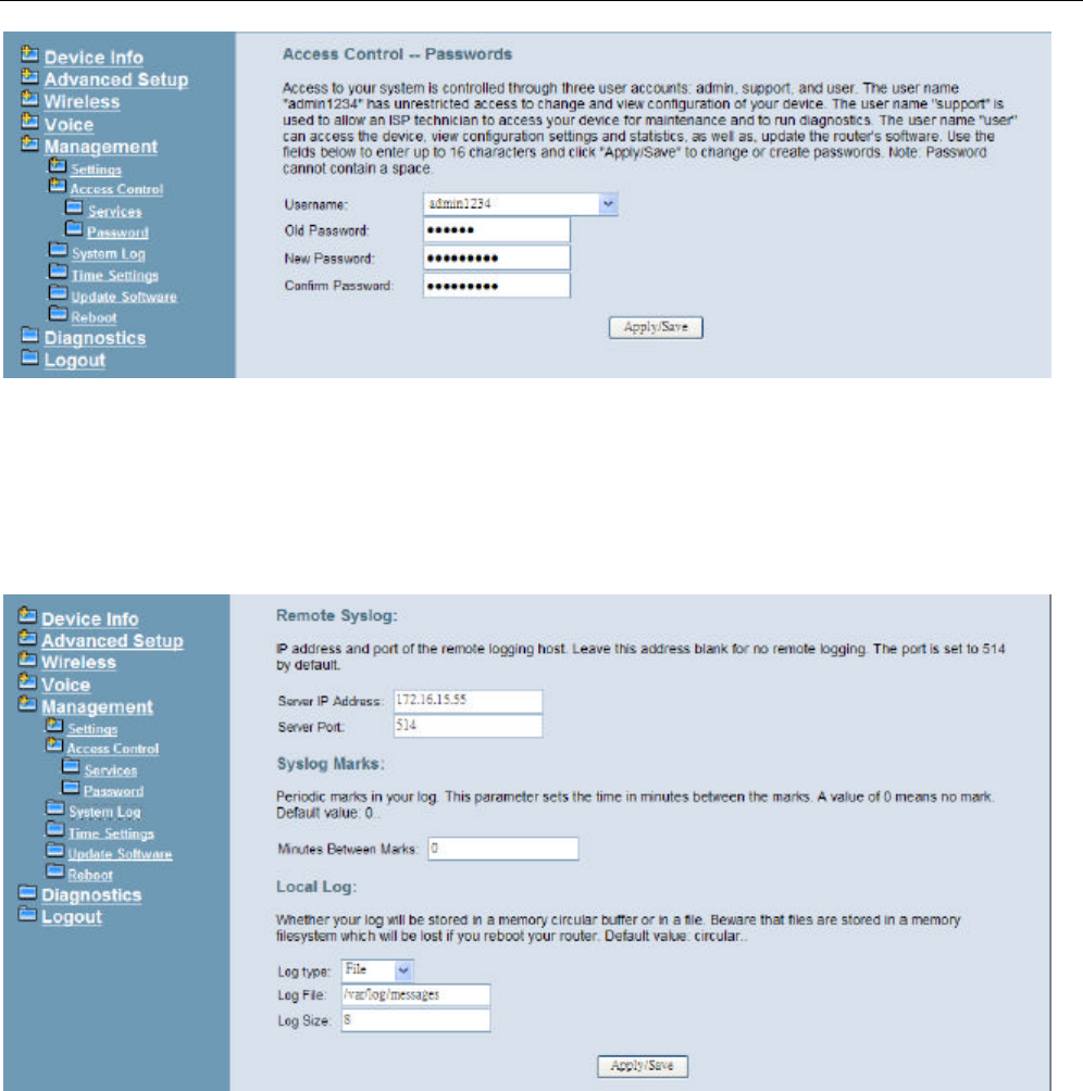
4.7.2.2 Password
In this page you can define the passwords for administrator, support, and user. The
Administrator has unrestricted access to change and view configuration of your IG7500.
The Support is used to allow an ISP technician to access your IG7500 for maintenance and
to run diagnostics. The User can access the IG7500, view configuration settings and
statistics, as well as, update the router’s software.
Use the password field to enter up to 16 characters. Note: Password cannot contain a
space. (Figure 4-29)
IG7500 Administration Manual
- 32 -
Figure 4-29. Management – Access Control – Password
4.7.3 System Log
This allows system administrator to view the system log. (Figure 4-30) When you configure
the system log options, The log messages can be saved in the internal memory filesystem.
The log messages can sent to the specified UDP port of the specified log server also. Click
“Apply/Save” button that you can save the new configuration.
Figure 4-30. Management – System Log
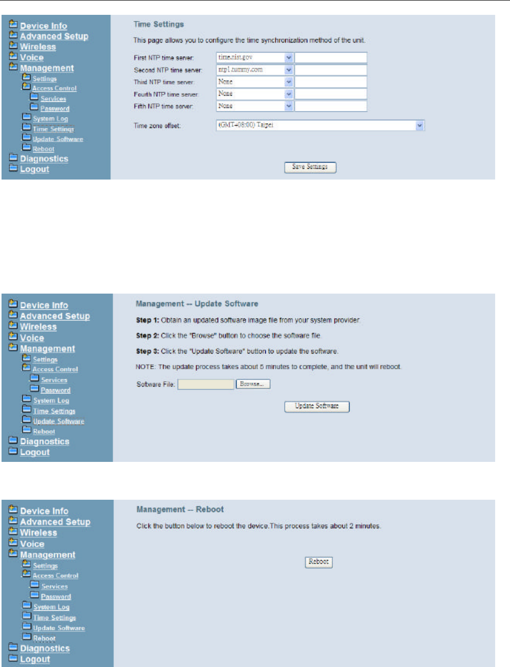
4.7.4 Time Setting
This item allows you to configure system’s time and the Daylight Saving Time.
4.7.4.1 Internet Time
This page allows you to configure the Internet time setting. IG7500 synchronize its system
time with NTP time server automatically (Figure 4-31).
IG7500 Administration Manual
- 33 -
Figure 4-31. Management – Time Setting – Internet Time – Automatically
4.7.5 Update Software
The new released software could be upgraded from the Local PC side or remotely. Click
the “Browse” to locate the new software image file in the PC. Then, click “Update Software”
to process the software update. NOTE: The upgrade process takes about 5 minutes to
complete, and your IG7500 will reboot. (Figure 4-32)
Figure 4-32. Management – Update Software
4.7.6 Reboot
Figure 4-33. Management – Save/Reboot
Click “Reboot” to reboot the IG7500. The IG7500 would automatically save the
configuration before reboot, so that modified settings would take effect after reboot. (Figure
4-33)
IG7500 Administration Manual
- 34 -
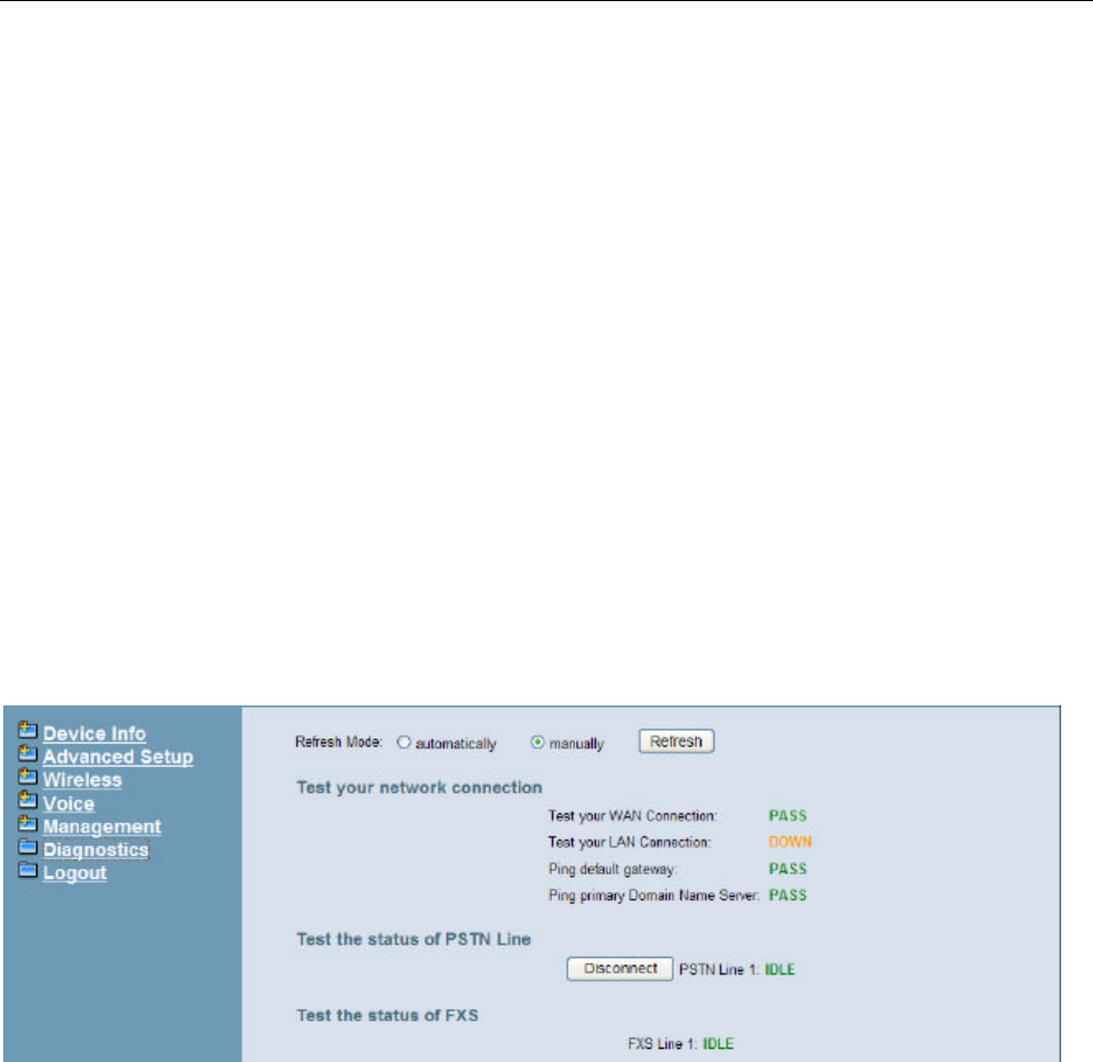
4.8 Diagnostics
This page provides the following information to users: (錯誤! 找不到參照來源。)
l The network connection information on the net.
l The status of IG7500's PSTN Line.
l The status of IG7500’s FXS.
1) Network Connection
PASS: Normally connected
FAIL: Connecting fail
DOWN: No connection
2) PSTN Line / FXS
FAILED: Connecting fail or registering failure
IDLE: The line is idle
N/A: The line is not available
Busy: The line is in use
For Refresh Mode, if user select automatically refresh, the web page will automatically
refresh for every 20 seconds.
Click “Disconnect” button will allow you release the selected trunk line or rescue the
blocked one.
4.9 Logout
Press “Logout”, you can logout the IG7500 web configuration page.

IG7500 Administration Manual
- 35 -
Appendix 1: Product Summary
Hardware
n 1 FXO port (PSTN)
n 1 FXS Port (fax)
n 1 10/100/1000 Ethernet WAN port
n 4 10/100 Ethernet LAN ports
n 802.11n access point
n 3 USB 2.0 host ports
n WPS button
n Power plug
n Reset button
Voice Features
n SIP : Compliant with IETF RFC3261 standards
n SDP : Compliant with IETF RFC2327 standards
n Codec : G.711u, G.711a, G726-16, G726-24, G726-32 and G.726-40 (G.729a
optional)
n T.168 echo cancellation, adaptive jitter buffer & T.38 fax support
TCP/IP Protocols
n IP Protocol (791)
n ARP (RFC 826) / RARP (RFC 903)
n ICMP (RFC792)
n TCP (RFC 793)
n UDP (RFC 768)
n SNTP
n DNS
n HTTP
n Telnet
n TFTP
n RTP
n Static Routing
n NAT with ALGs
IP Address Assignment
n Static
n Dynamic
n Subnet Mask
n Primary and Secondary DNS
n DHCP Server (RFC 2131-2132)
n DHCP Client (RFC 2132)
Virtual Server
n Virtual Server
n DMZ
QoS
n IP ToS function (RFC 1349)

IG7500 Administration Manual
- 36 -
n Priority queues for upstream traffic based on ToS field.
n Bandwidth Control
3G
n 3G HSDPA dongles for WAN backup and 3G interface
n Bandrich, Huawei, ZTE and D-Link dongles will be supported by default, other
dongles will be supported upon request
VoIP Protocols
n SIP (RFC 3261)
n SDP(RFC2327, RFC3264)
n Real Time Protocol (RTP ; RFC 1889)
n MD5 (RFC3261 HTTP) digest authentication
n G.168 Echo Cancellation
n Voice Codec: G.711u, G.711a, G726-16, G726-24, G726-32 and G.726-40 (G.729a
optional)
n Support FAX/modem tone detection and auto-fallback to G.711
n T.38
FXO/FXS SIP Account
n SIP message, including INVITE, re-INVITE, ACK, CANCEL, OPTIONS, BYE,
REGISTER, INFO, REFER, SUSCRIBE/NOTIFY and REPLACE messages.
n SIP Outbound Proxy, SIP Proxy and Registrar
n Auto-Registration when power-on or period
n Session Timer support
n Support IP address, domain name, user name, display name for SIP URL
Digital Audio
n Codec: G.711 a-law/µ-law 64Kbps, G.726-16/24/32/40, G.729
n SIP Call Offer /Answer: Codec auto capacity exchange
n Echo Cancellation: G.168 for each voice line
n Silence Detection/Suppression
n Comfort Noise Generation
n Adaptive jitter buffer
n Different frame size support (10,20,30,40, 50, and 60ms)
n Packet loss concealment
n Out-band (RFC2833) and In-band DTMF
Configuration Management
n LAN/WAN management via Telnet interface or Web-based browser interface
n Firmware upgrade available by TFTP/ HTTP
n Status display and event report from Web-based management
n Configuration Save and Restore
n Reset to factory default
Radio - WLAN
n Standard : IEEE 802.11b/g/n
n 4 SSID with WEP, WPA and WPA2 personal
n Frequency Range (Range depends on different country)
Remote Diagnostic

IG7500 Administration Manual
- 37 -
n Syslog
n Device Diagnostic, Enable remote test following:
Test the connection to your local network,
The connection to your Internet service provider,
The status of PSTN Line,
The status of FXS
Power Requirement
n Input : Voltage Range 90~264 VAC
n Output : 12VDC / 1.5A
Operating Environment
n Temperature : 0~40℃
n Humidity : 10 to 90%, non-condensing
Physical Specification
n Dimension : 160(W) x 220(L) x 82(D) (mm)
Notice : The changes or modifications not expressly approved by the party responsible
for compliance could void the user’s authority to operate the equipment.
IMPORTANT NOTE:
To comply with the FCC RF exposure compliance requirements, the antenna(s)
used for this transmitter must be installed to provide a separation distance of at least 20 cm
from all persons and must not be co-located or operating in conjunction with any other
antenna or transmitter. No change to the antenna or the device is permitted. Any change to
the antenna or the device could result in the device exceeding the RF exposure requirements
and void user’s authority to operate the device.
FCC INFORMATION
The Federal Communication Commission Radio Frequency Interference
Statement includes the following paragraph:
The equipment has been tested and found to comply with the limits for a Class
B Digital Device, pursuant to part 15 of the FCC Rules. These limits are designed
to provide reasonable protection against harmful interference in a residential
installation. This equipment generates, uses and can radiate radio frequency
energy and, if not installed and used in accordance with the instruction, may cause
harmful interference to radio communication. However, there is no grantee that
interference will not occur in a particular installation. If this equipment dose cause
harmful interference to radio or television reception, which can be determined by
turning the equipment off and on , the user is encouraged to try to correct the
interference by one or more of the following measures:
--Reorient or relocate the receiving antenna.
--Increase the separation between the equipment and receiver.
--Connect the equipment into an outlet on a circuit different from that to which the
receiver is connected.
--Consult the dealer or an experienced radio/TV technician for help.