Tecom Co KRD90154 Access Point User Manual
Tecom Co Ltd Access Point
UserManual.wiki
>
Tecom Co
>
KRD90154 User Manual
User Manual
Navigation menu
Upload a User Manual
Namespaces
Wiki Guide
HTML
PDF
Info
Views
User Manual
Discussion / Help
Navigation
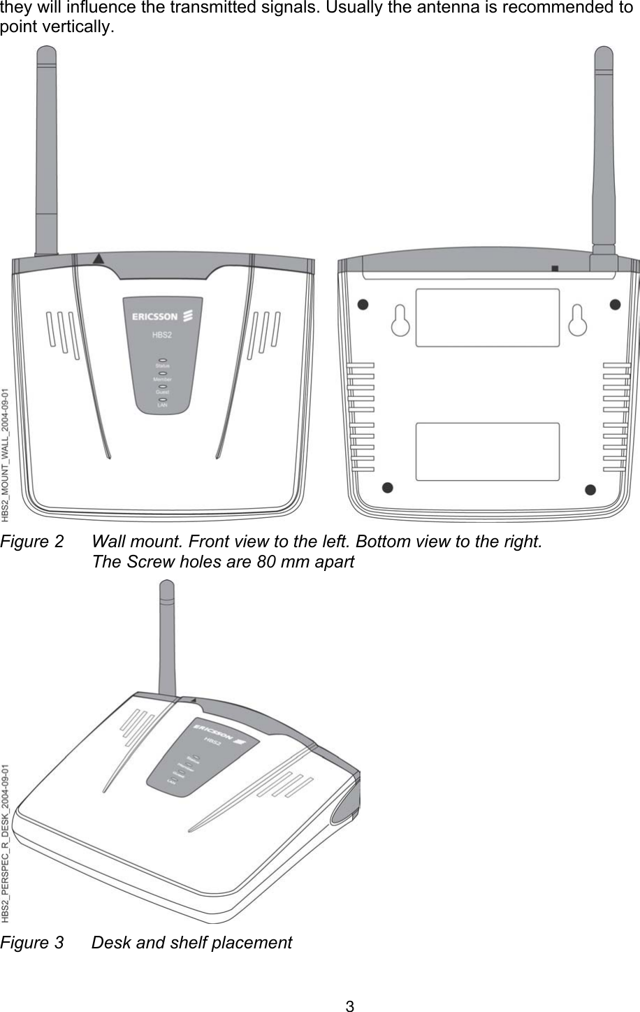
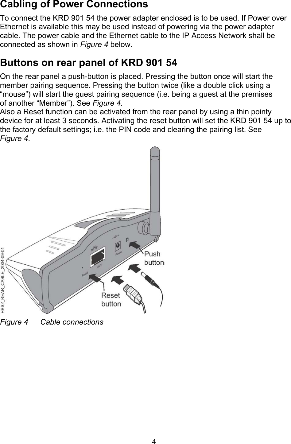
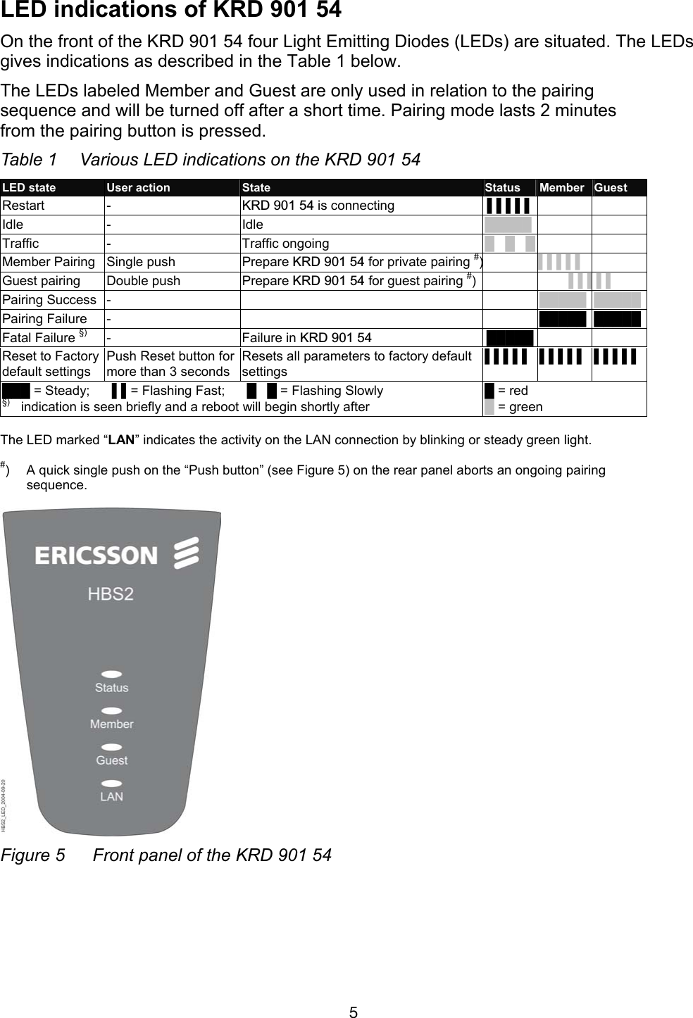
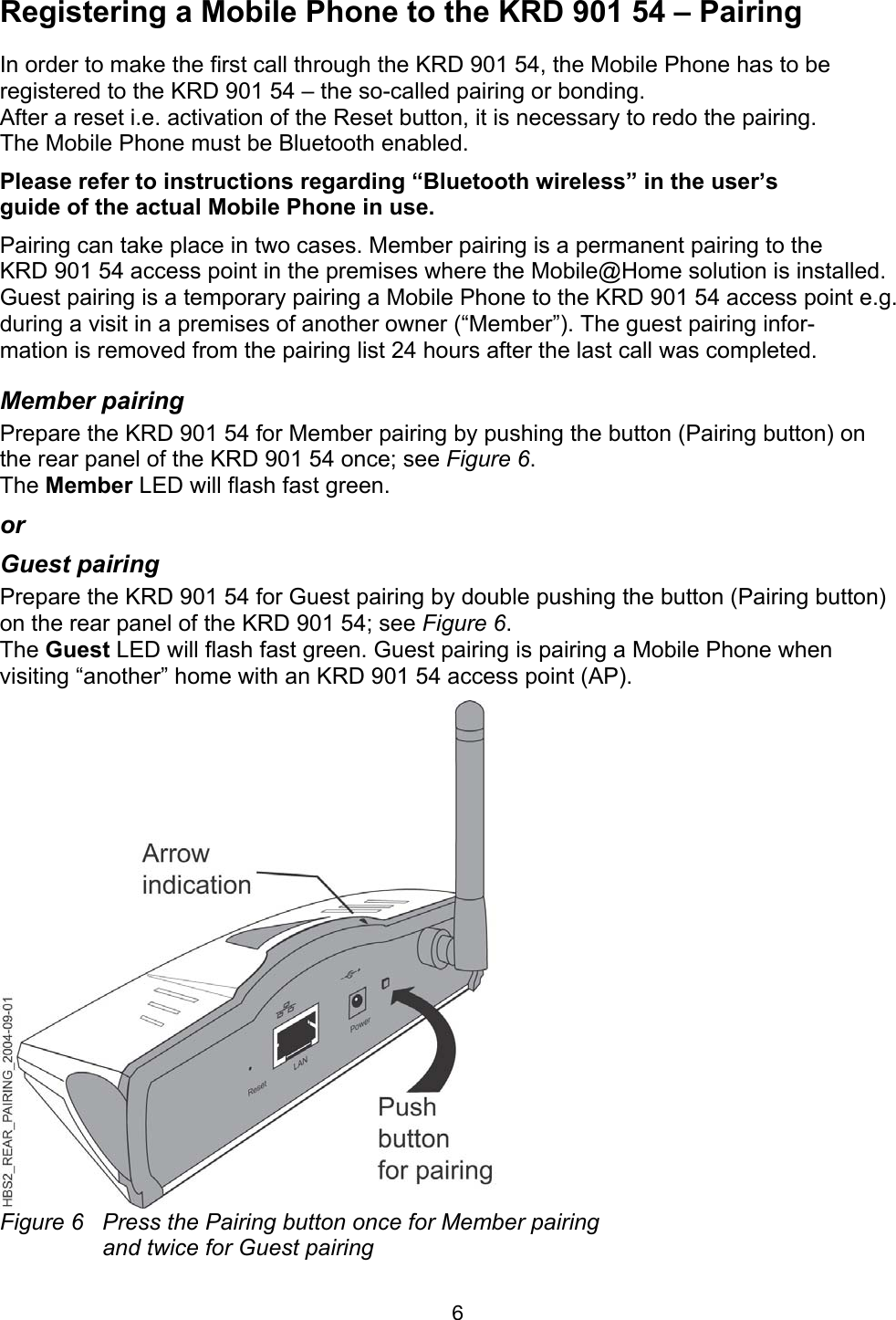
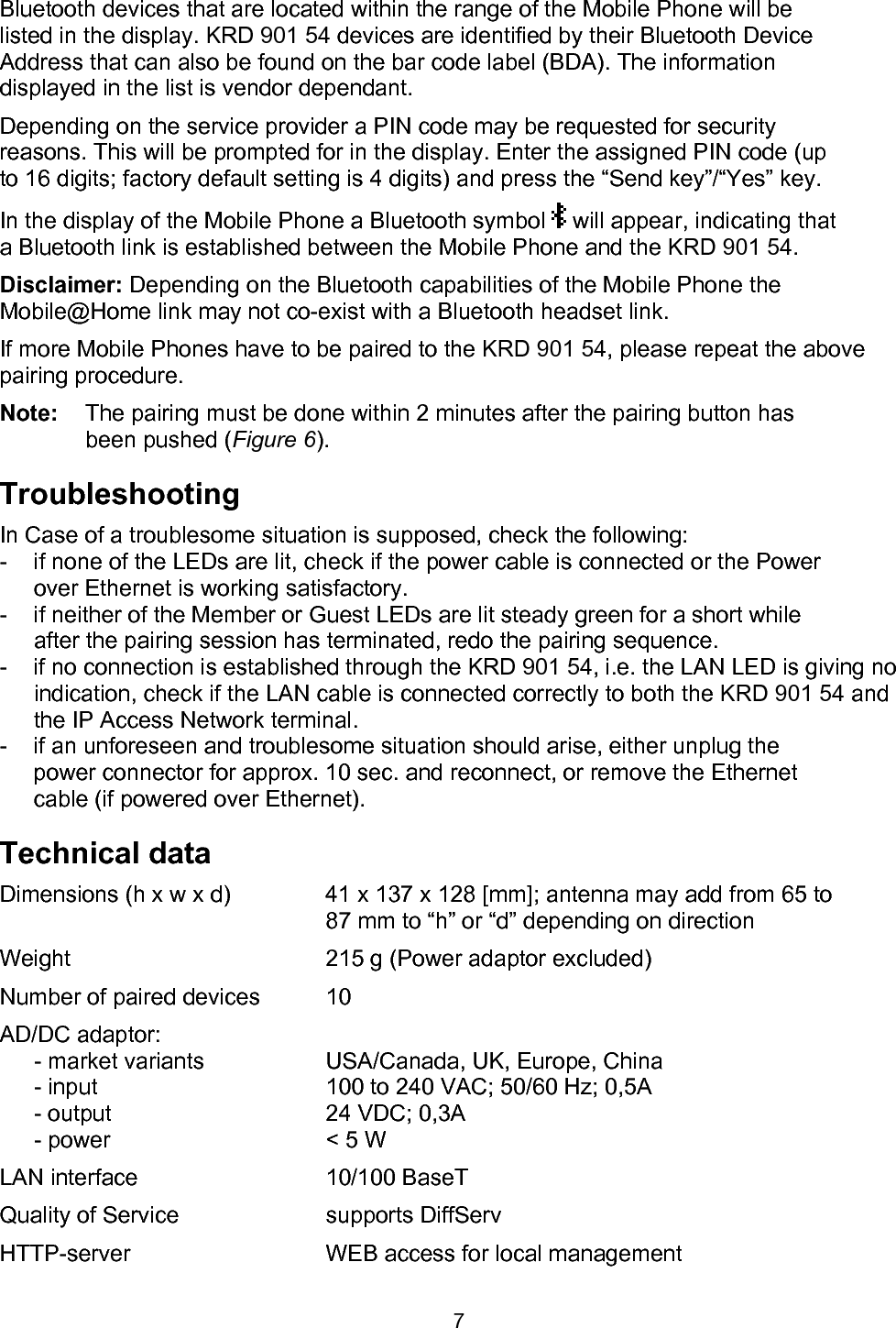
![Bluetooth devices that are located within the range of the Mobile Phone will be listed in the display. KRD 901 54 devices are identified by their Bluetooth Device Address that can also be found on the bar code label (BDA). The information displayed in the list is vendor dependant. Depending on the service provider a PIN code may be requested for security reasons. This will be prompted for in the display. Enter the assigned PIN code (up to 16 digits; factory default setting is 4 digits) and press the “Send key”/“Yes” key. In the display of the Mobile Phone a Bluetooth symbol will appear, indicating that a Bluetooth link is established between the Mobile Phone and the KRD 901 54. Disclaimer: Depending on the Bluetooth capabilities of the Mobile Phone the Mobile@Home link may not co-exist with a Bluetooth headset link. If more Mobile Phones have to be paired to the KRD 901 54, please repeat the above pairing procedure. Note: The pairing must be done within 2 minutes after the pairing button has been pushed (Figure 6). Troubleshooting In Case of a troublesome situation is supposed, check the following: - if none of the LEDs are lit, check if the power cable is connected or the Power over Ethernet is working satisfactory. - if neither of the Member or Guest LEDs are lit steady green for a short while after the pairing session has terminated, redo the pairing sequence. - if no connection is established through the KRD 901 54, i.e. the LAN LED is giving no indication, check if the LAN cable is connected correctly to both the KRD 901 54 and the IP Access Network terminal. - if an unforeseen and troublesome situation should arise, either unplug the power connector for approx. 10 sec. and reconnect, or remove the Ethernet cable (if powered over Ethernet). Technical data Dimensions (h x w x d) 41 x 137 x 128 [mm]; antenna may add from 65 to 87 mm to “h” or “d” depending on direction Weight 215 g (Power adaptor excluded) Number of paired devices 10 AD/DC adaptor: - market variants USA/Canada, UK, Europe, China - input 100 to 240 VAC; 50/60 Hz; 0,5A - output 24 VDC; 0,3A - power < 5 W LAN interface 10/100 BaseT Quality of Service supports DiffServ HTTP-server WEB access for local management 7](https://usermanual.wiki/Tecom-Co/KRD90154/User-Guide-484905-Page-8.png)