Tecom Co WL504X Wireless LAN Router User Manual
Tecom Co Ltd Wireless LAN Router
UserManual.wiki
>
Tecom Co
>
WL504X User Manual
User Manual
Navigation menu
Upload a User Manual
Namespaces
Wiki Guide
HTML
PDF
Info
Views
User Manual
Discussion / Help
Navigation

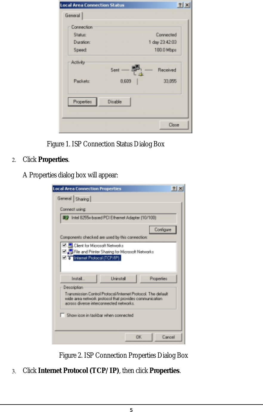
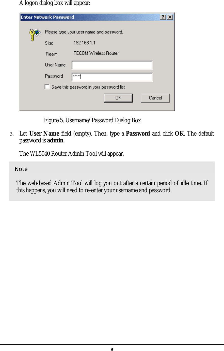
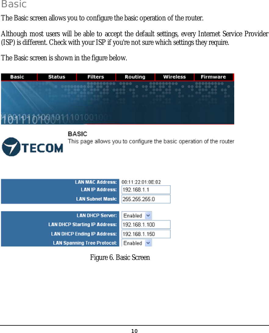
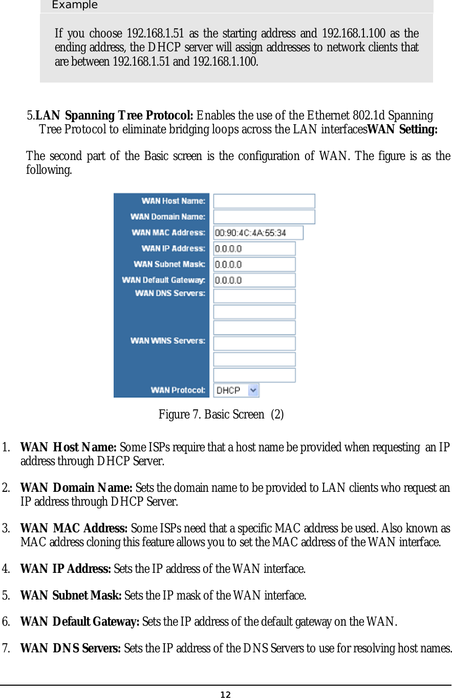
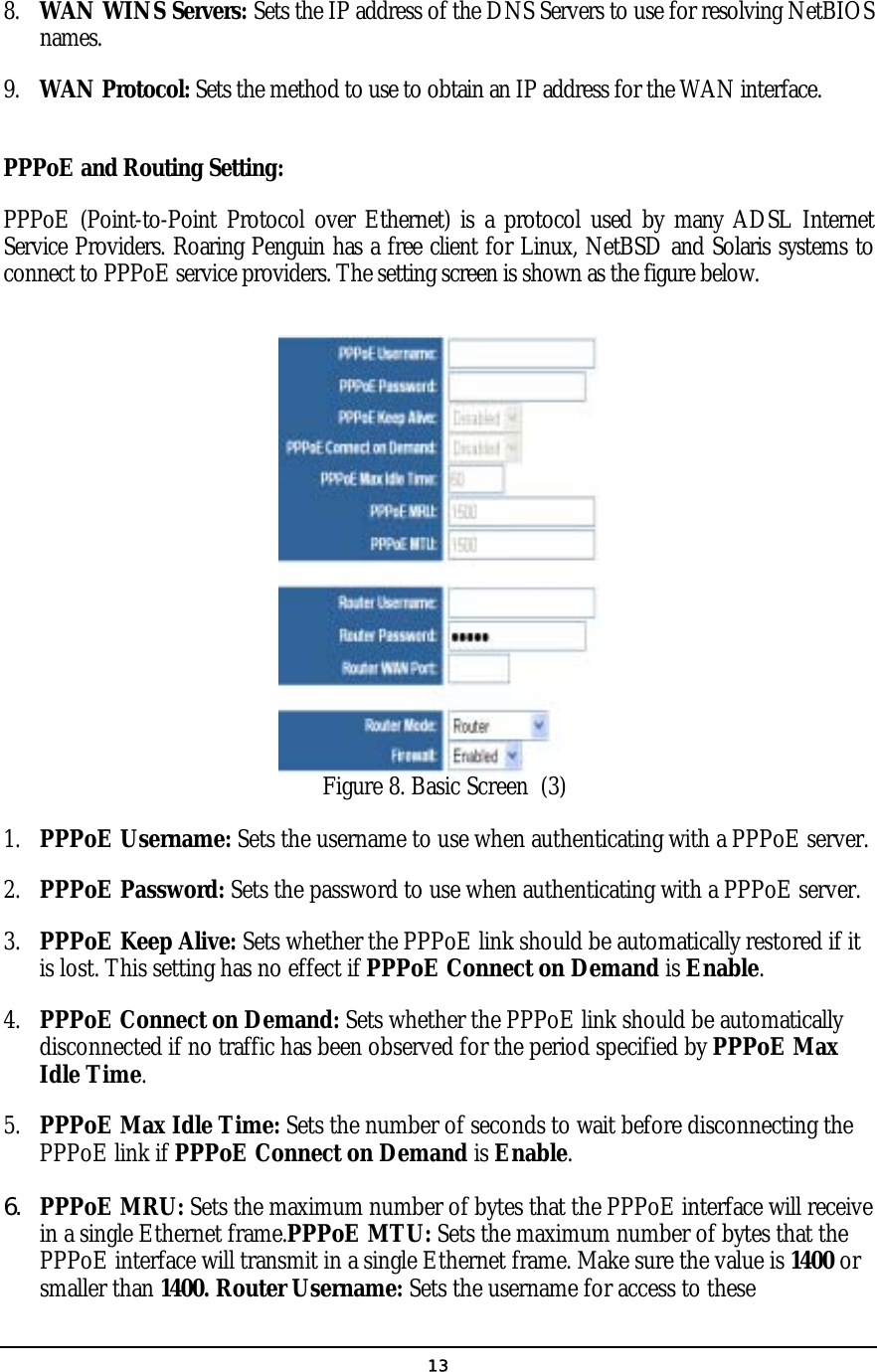
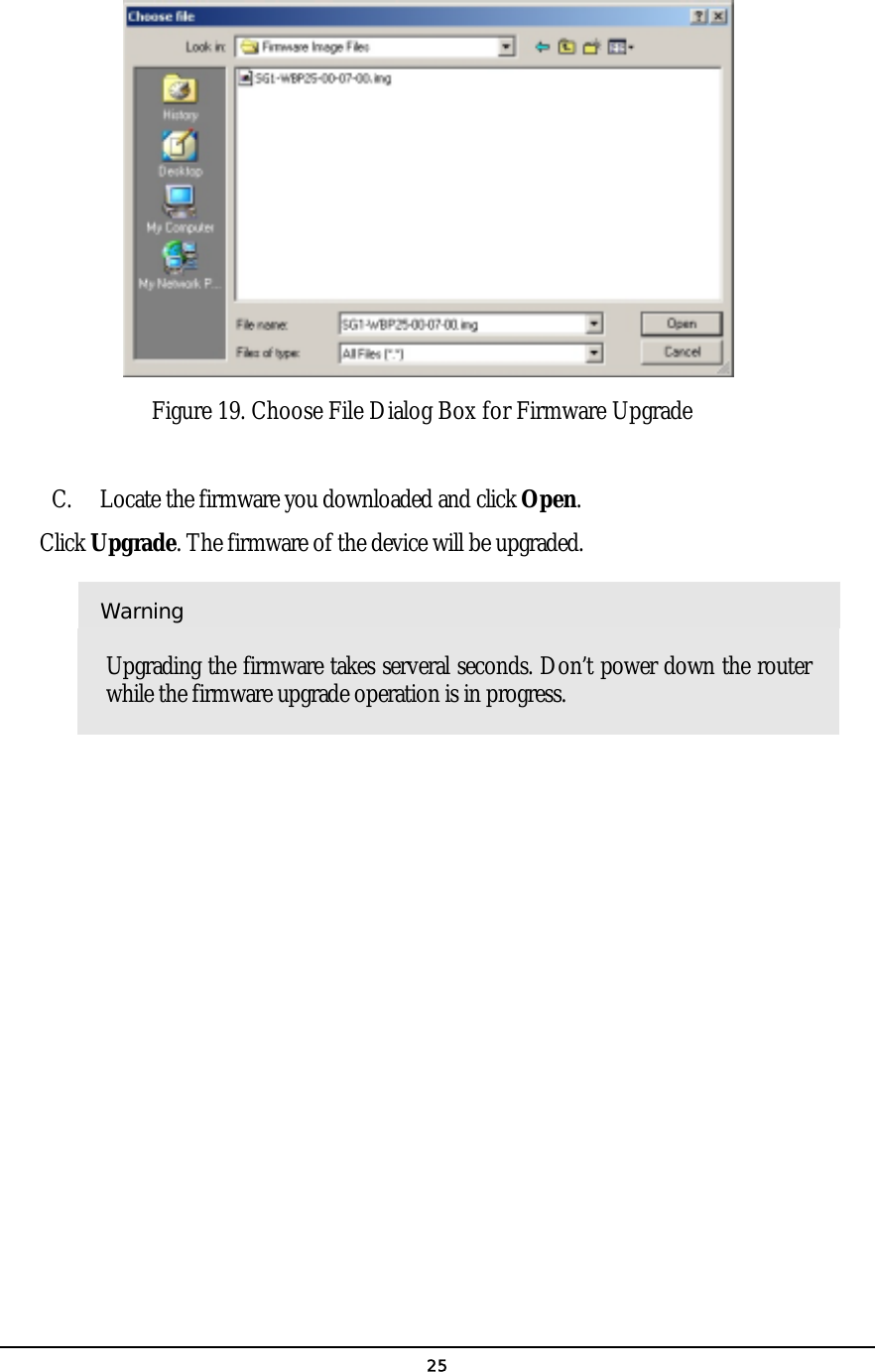
![4Preparing Your Network In this chapter, you’ll learn what to do before configuring your router. efore you can configure your router, you need to set up all the computers on your network for TCP/IP networking. You also need to know certain information from your ISP. Configuring Windows for IP Networking You need to configure each computer in your network for TCP/IP networking. If you plan to use the DHCP feature (recommended), you should configure each computer to receive an IP address automatically. See the procedure below for instructions. If you don’t plan to use DHCP, you’ll need to manually assign an IP address to each computer. Refer to your Windows documentation for instructions on how to do this. TO CONFIGURE WINDOWS TO RECEIVE DYNAMIC IP ADRESSES: 1. Click Start, then choose Settings -> Network and Dial-up Connections -> [name of your ISP connection]. A Status dialog box will appear: Chapter 2 B](https://usermanual.wiki/Tecom-Co/WL504X/User-Guide-339745-Page-5.png)