Tecom Co WM5347N WiMAX Indoor CPE User Manual WM5347N v1 3b nc
Tecom Co Ltd WiMAX Indoor CPE WM5347N v1 3b nc
UserManual.wiki
>
Tecom Co
>
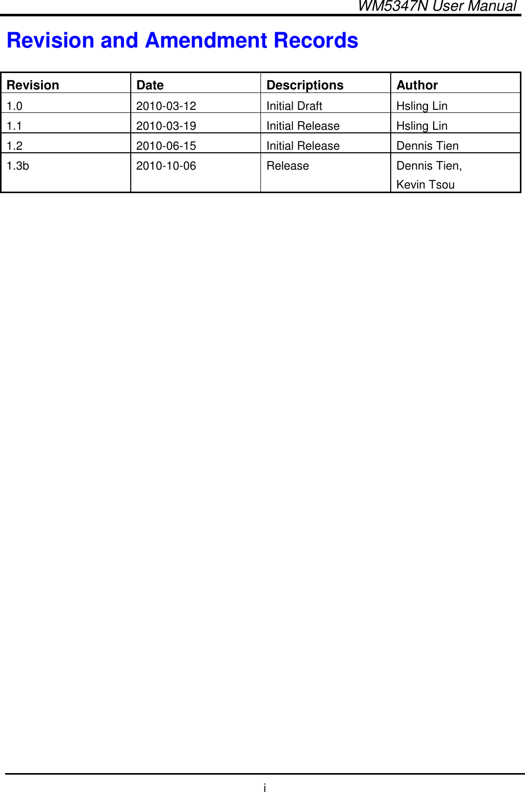
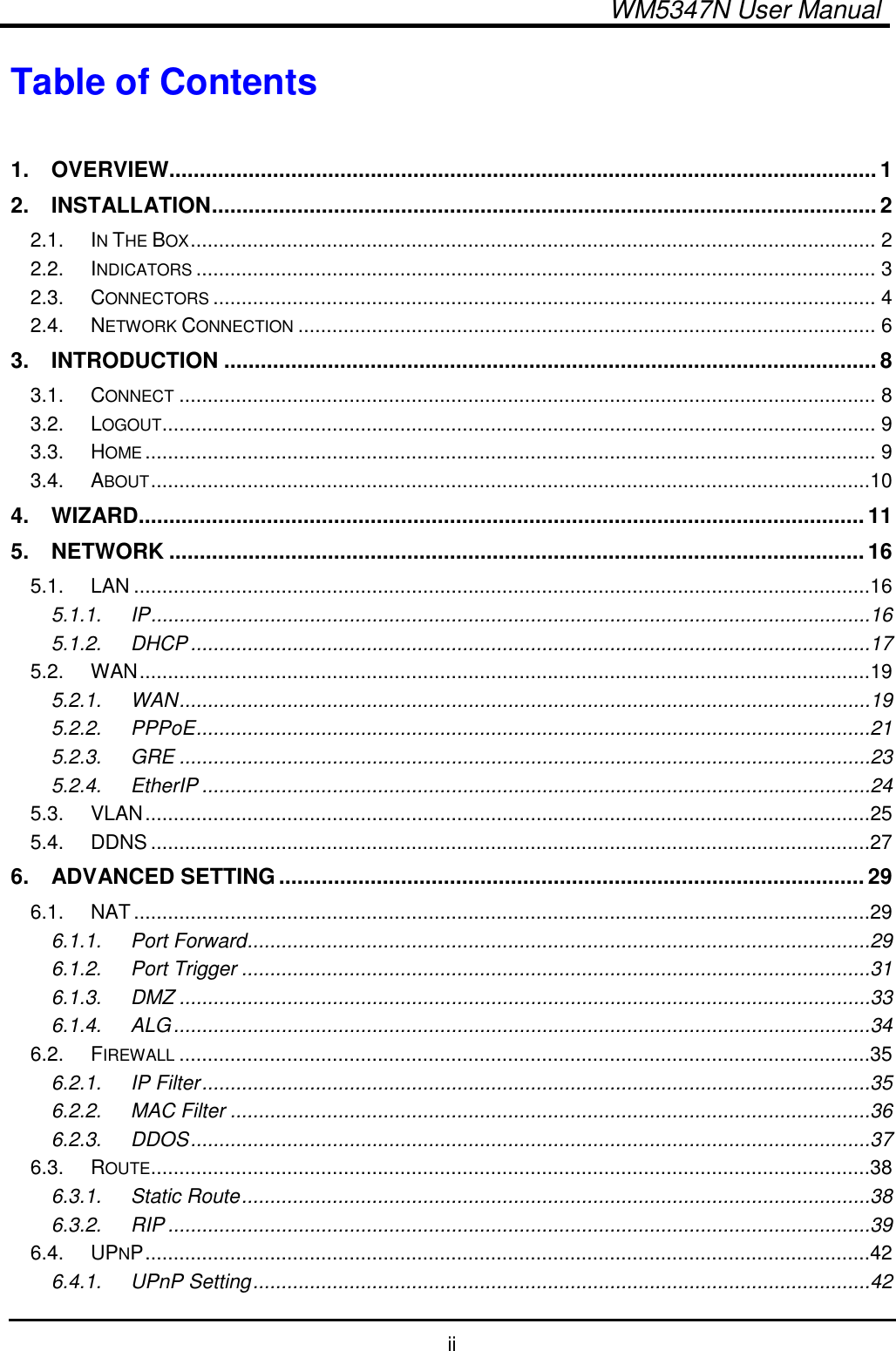
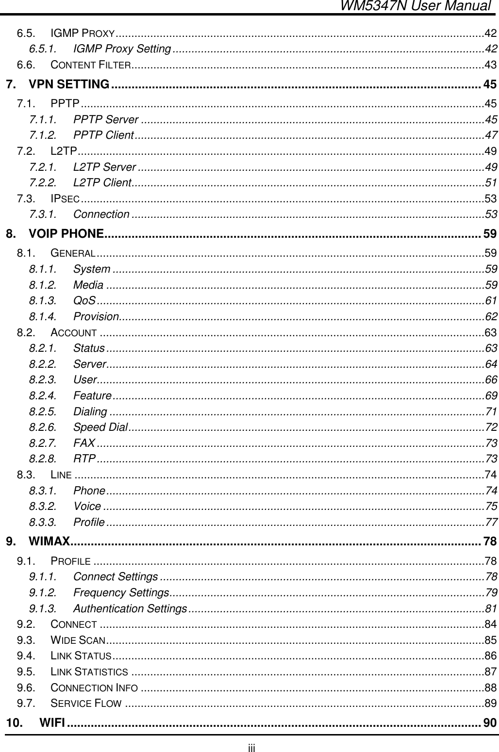
WM5347N User Manual
>
user manual
Contents
1.
user manual
2.
revised manual
3.
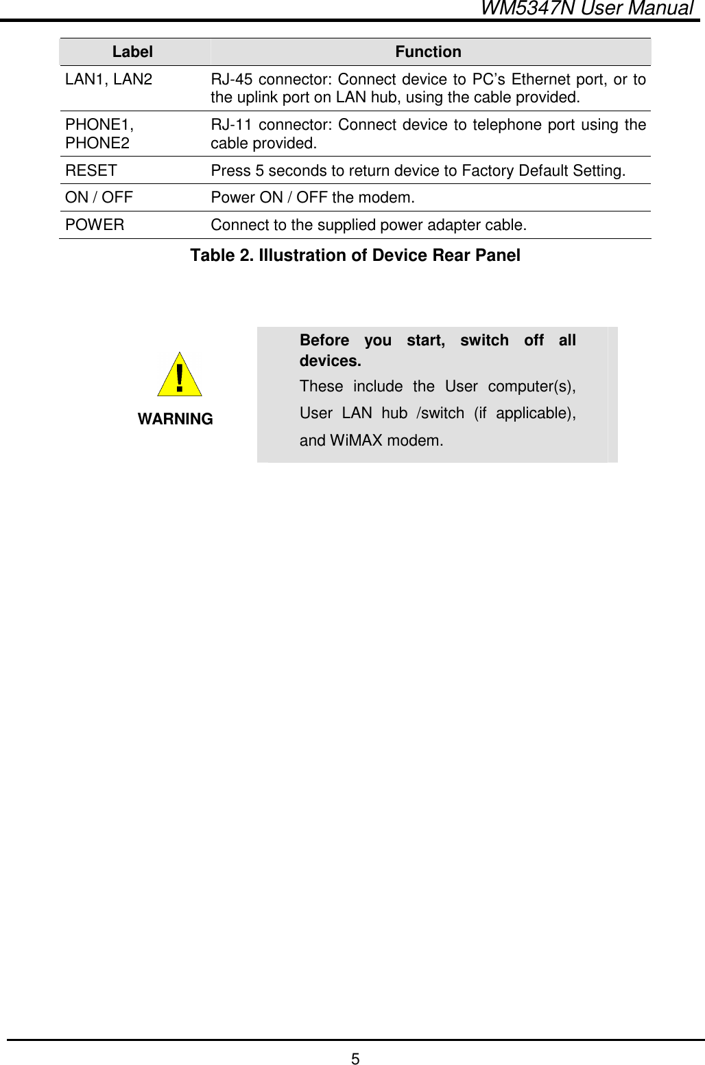
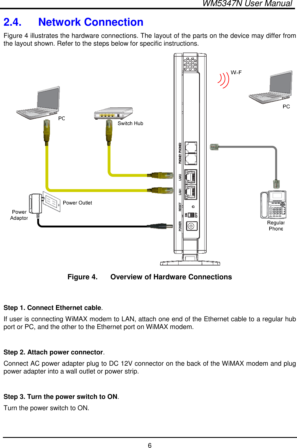
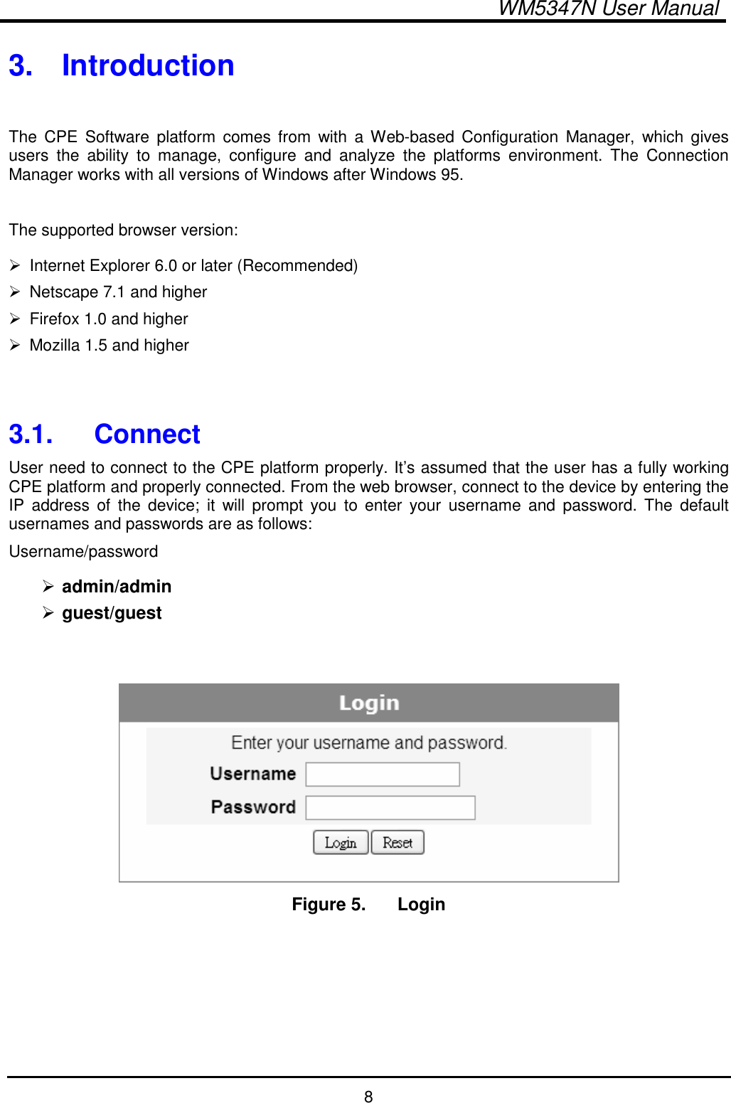
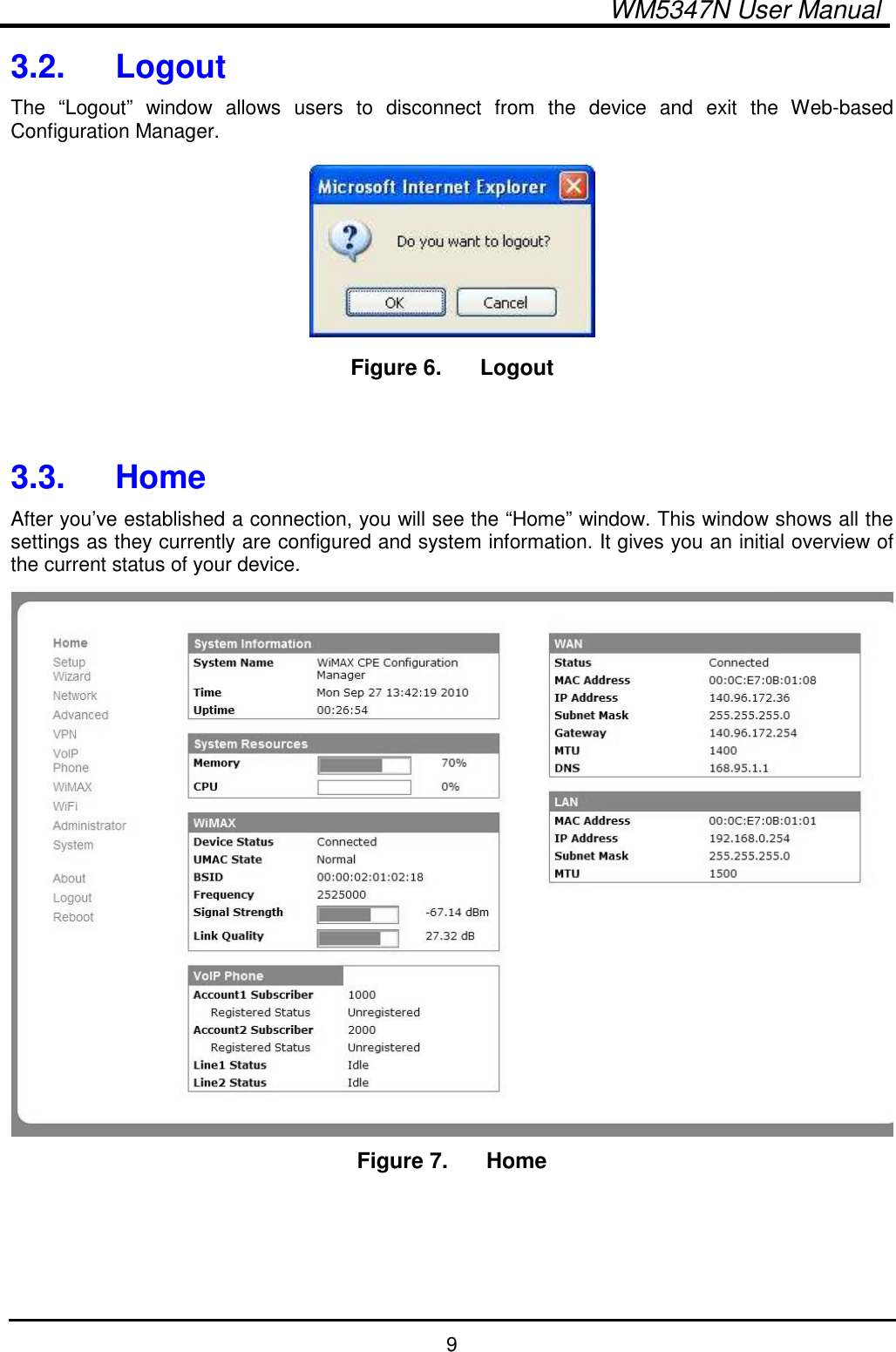
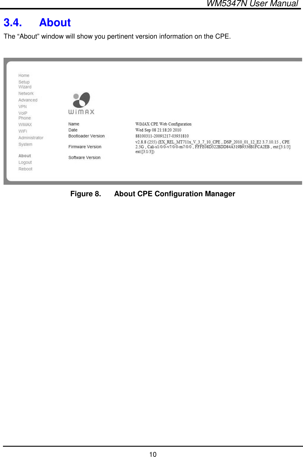
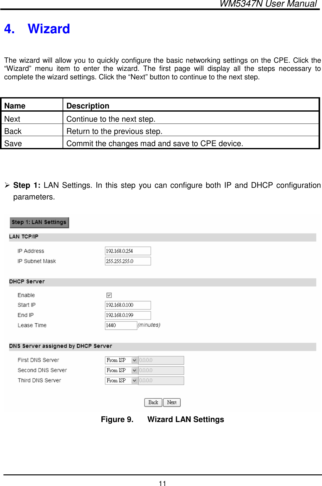
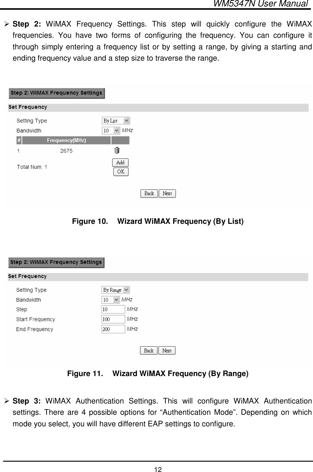
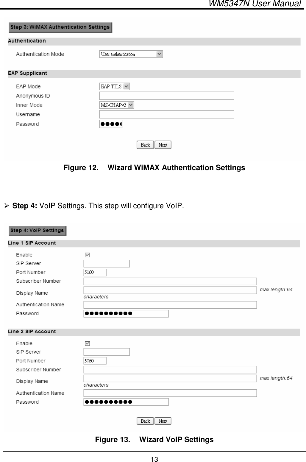
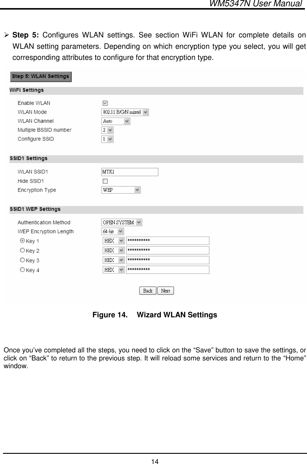
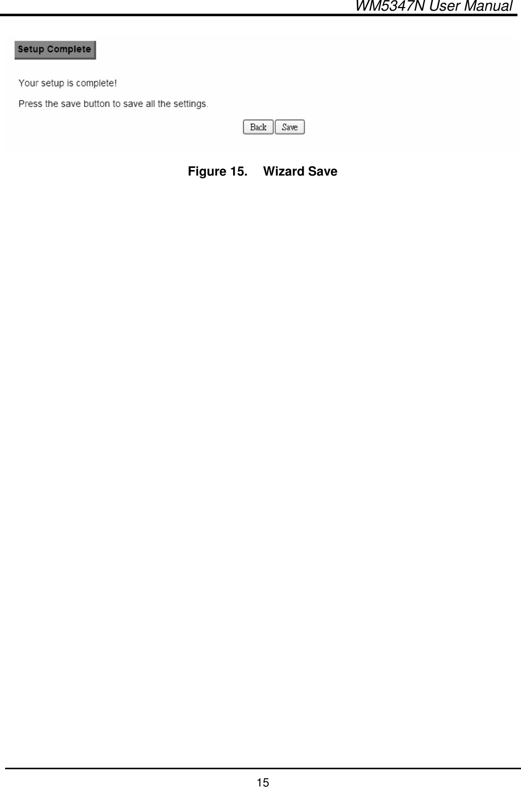
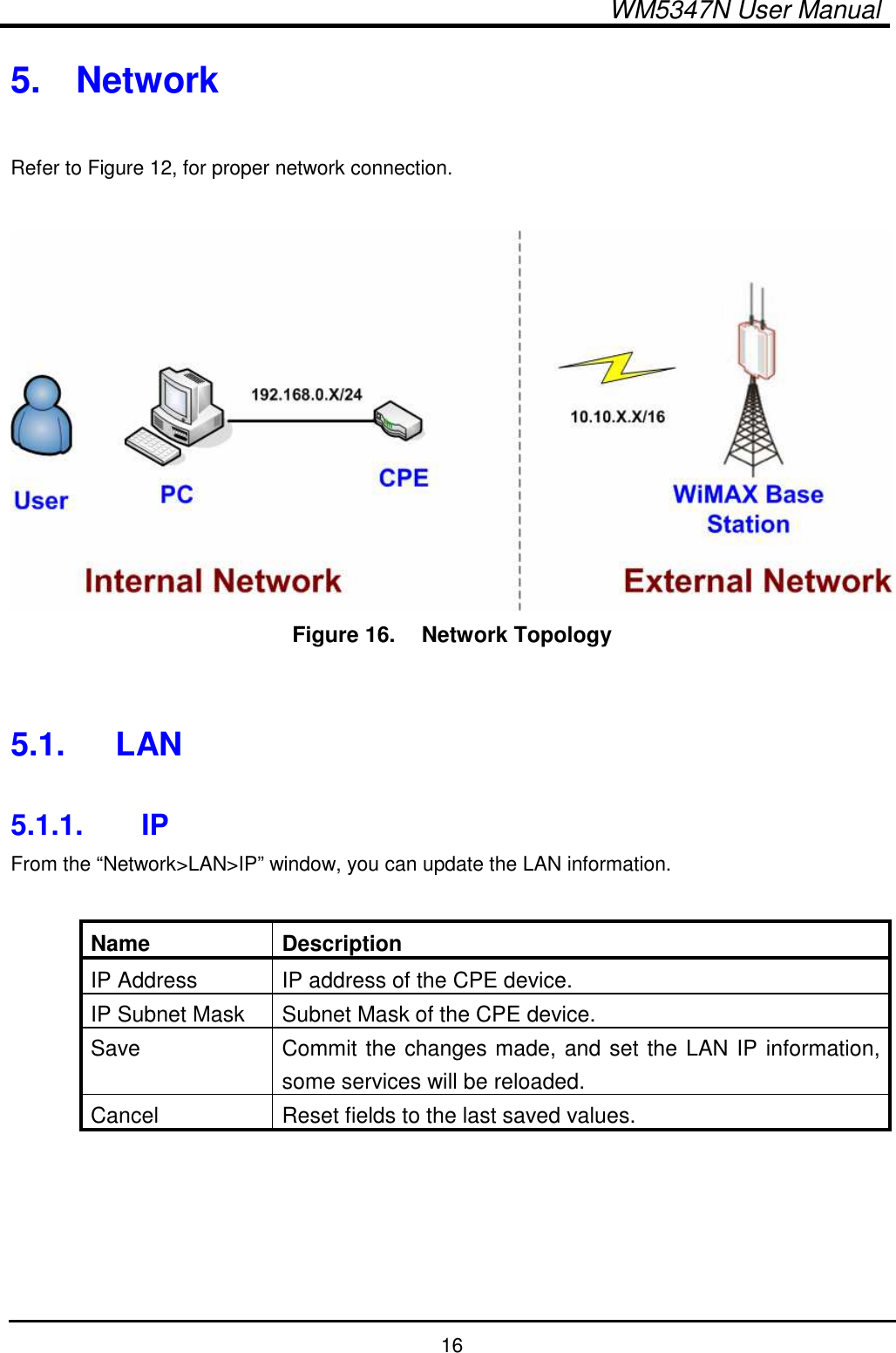
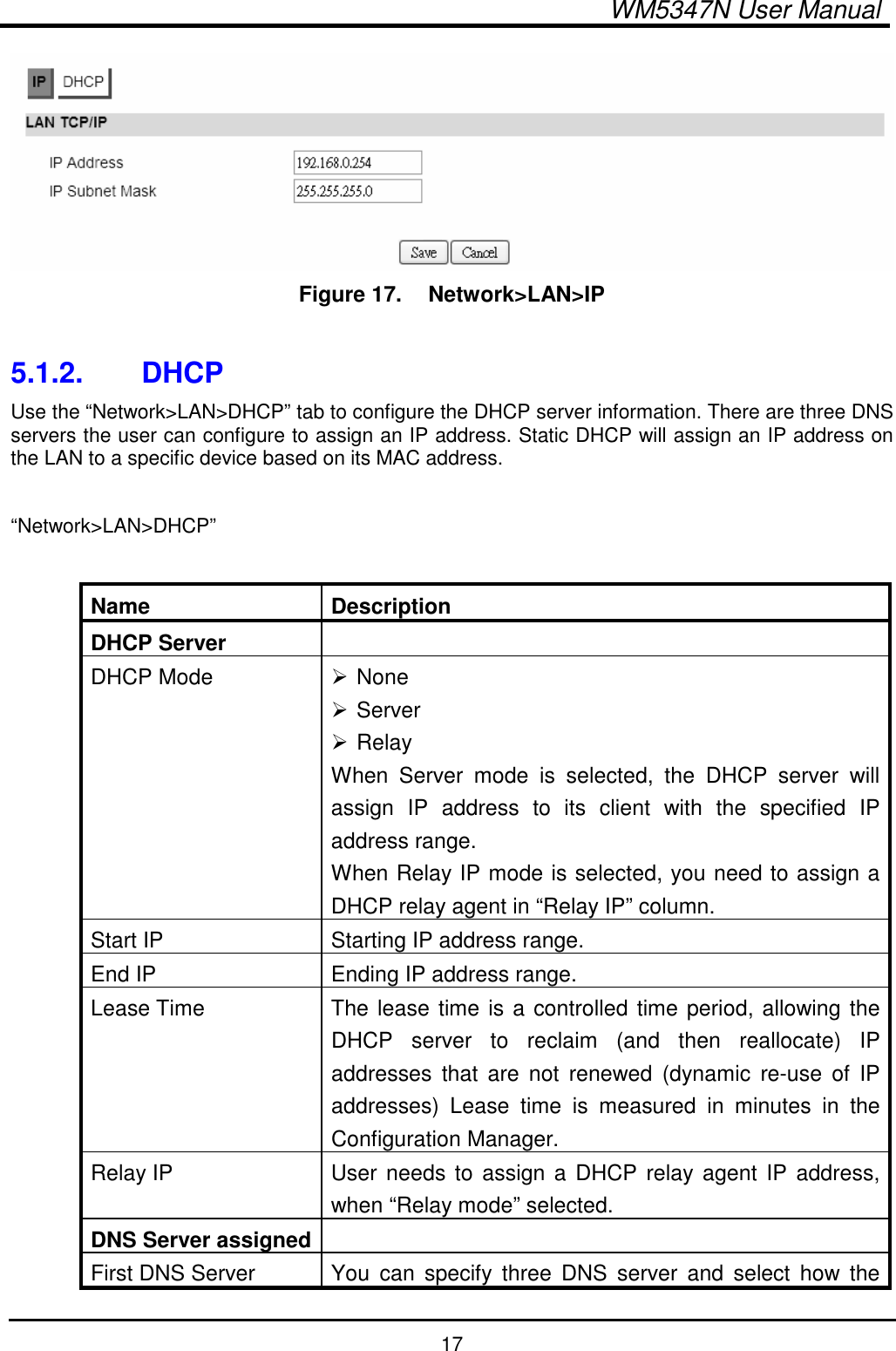
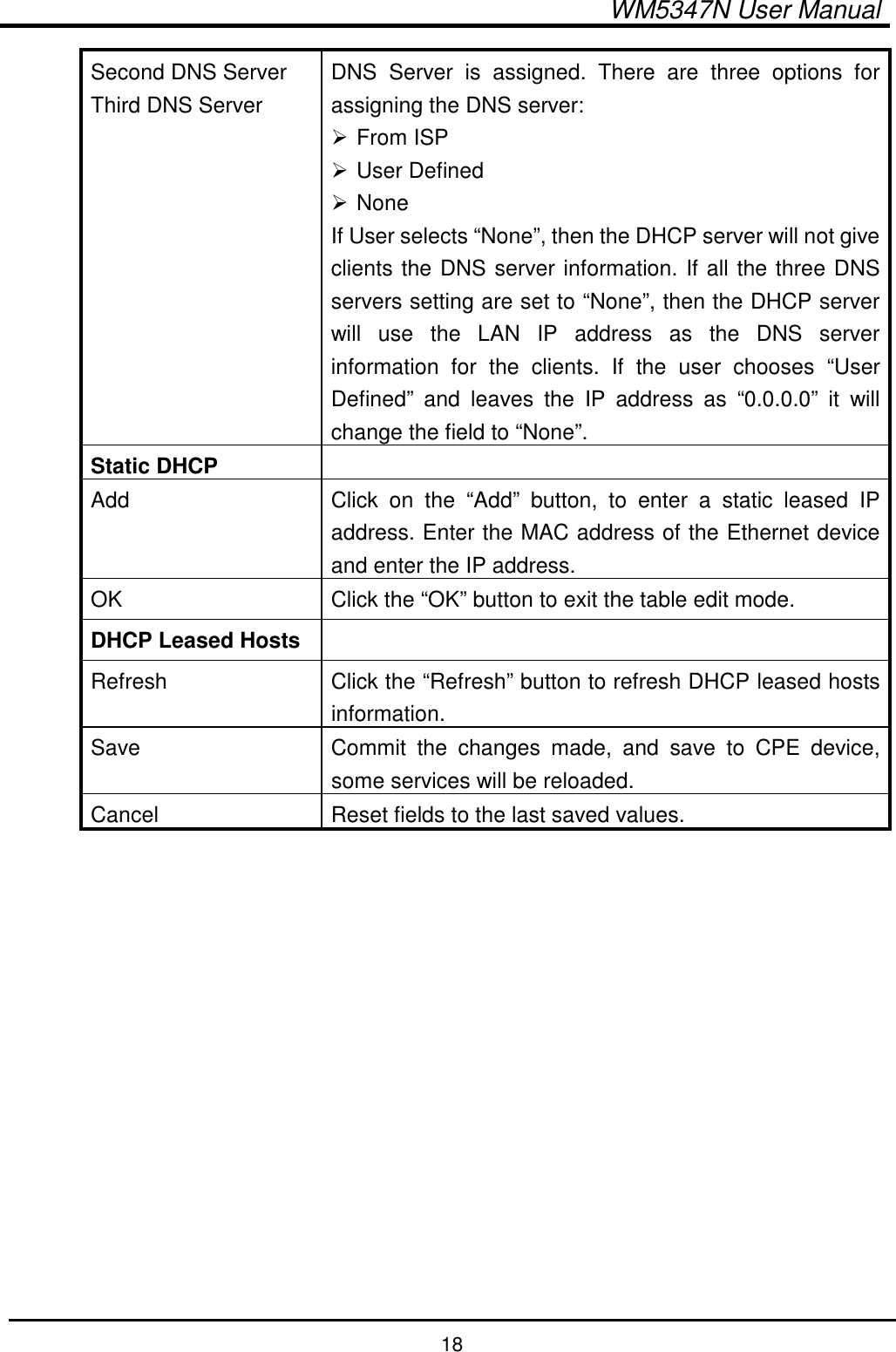
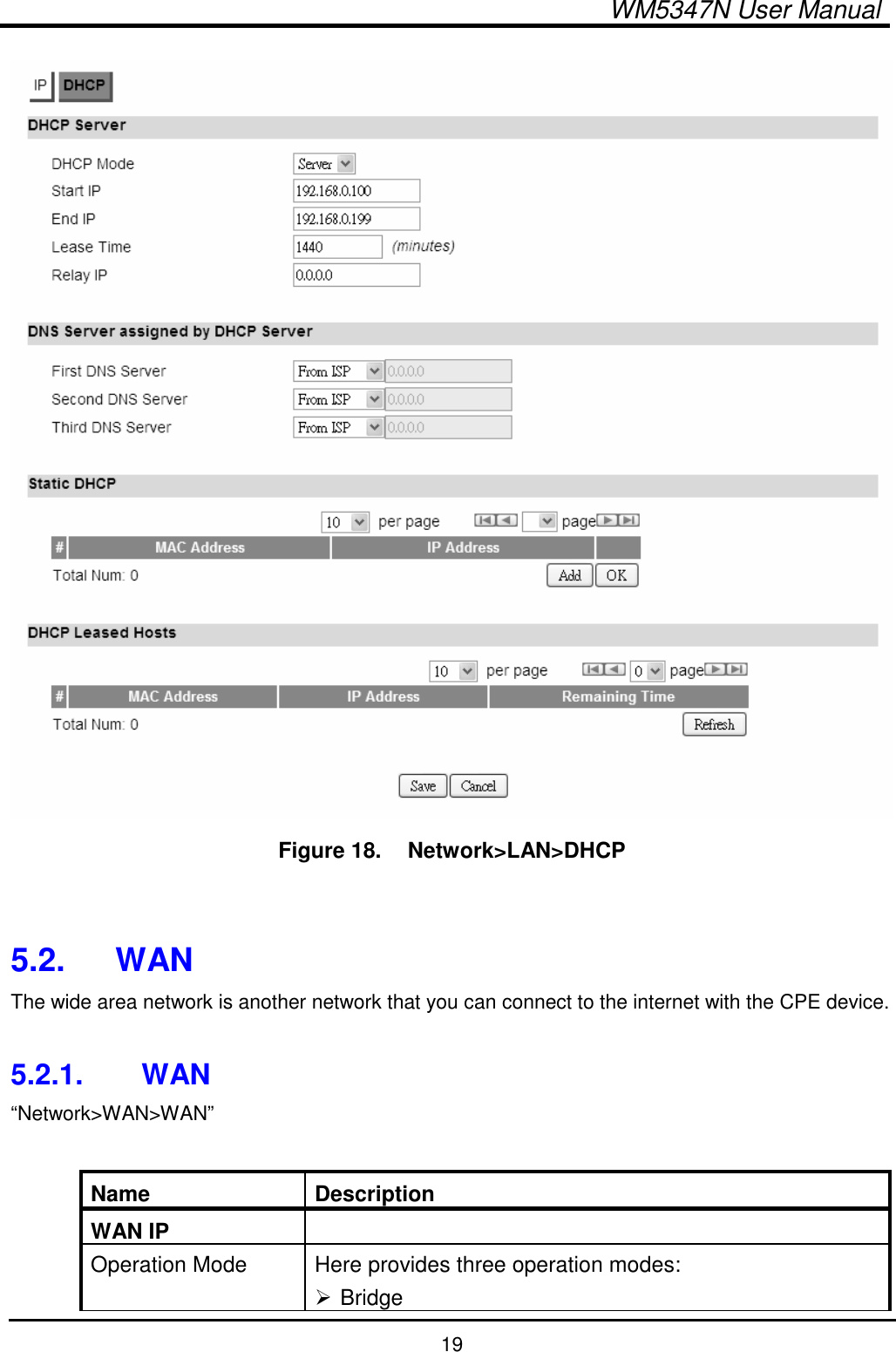
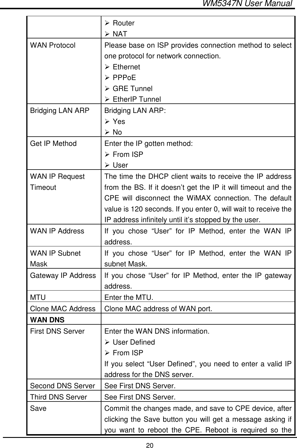
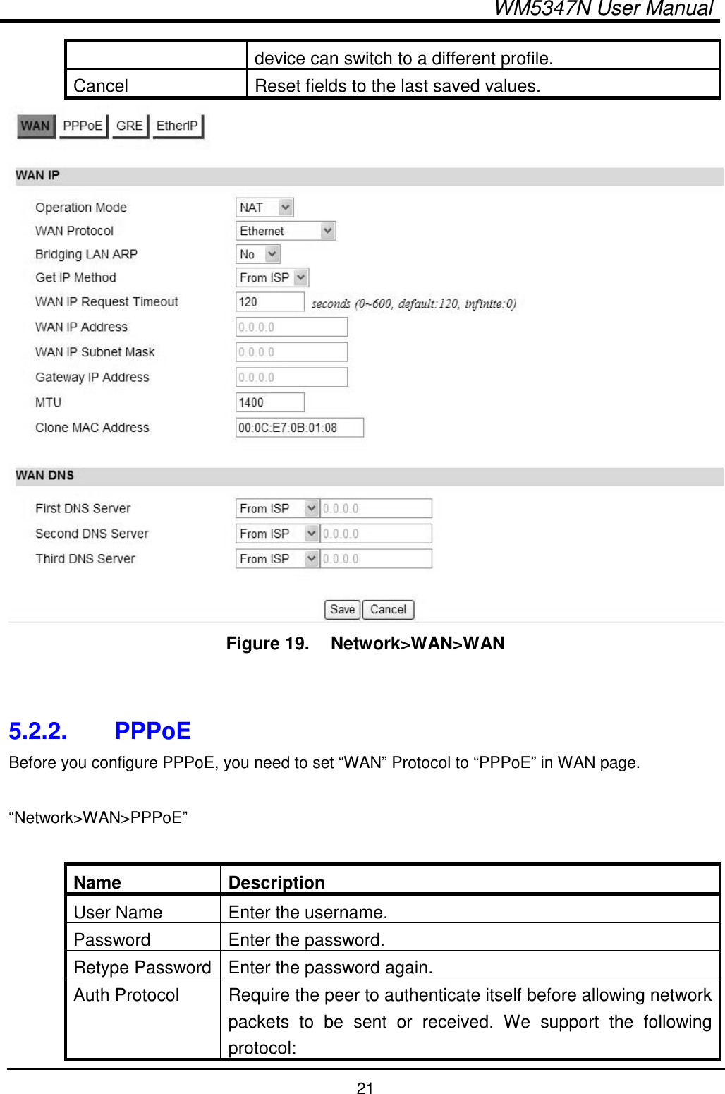
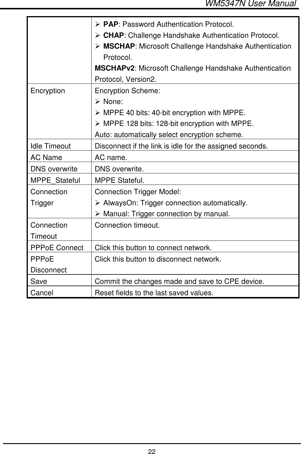
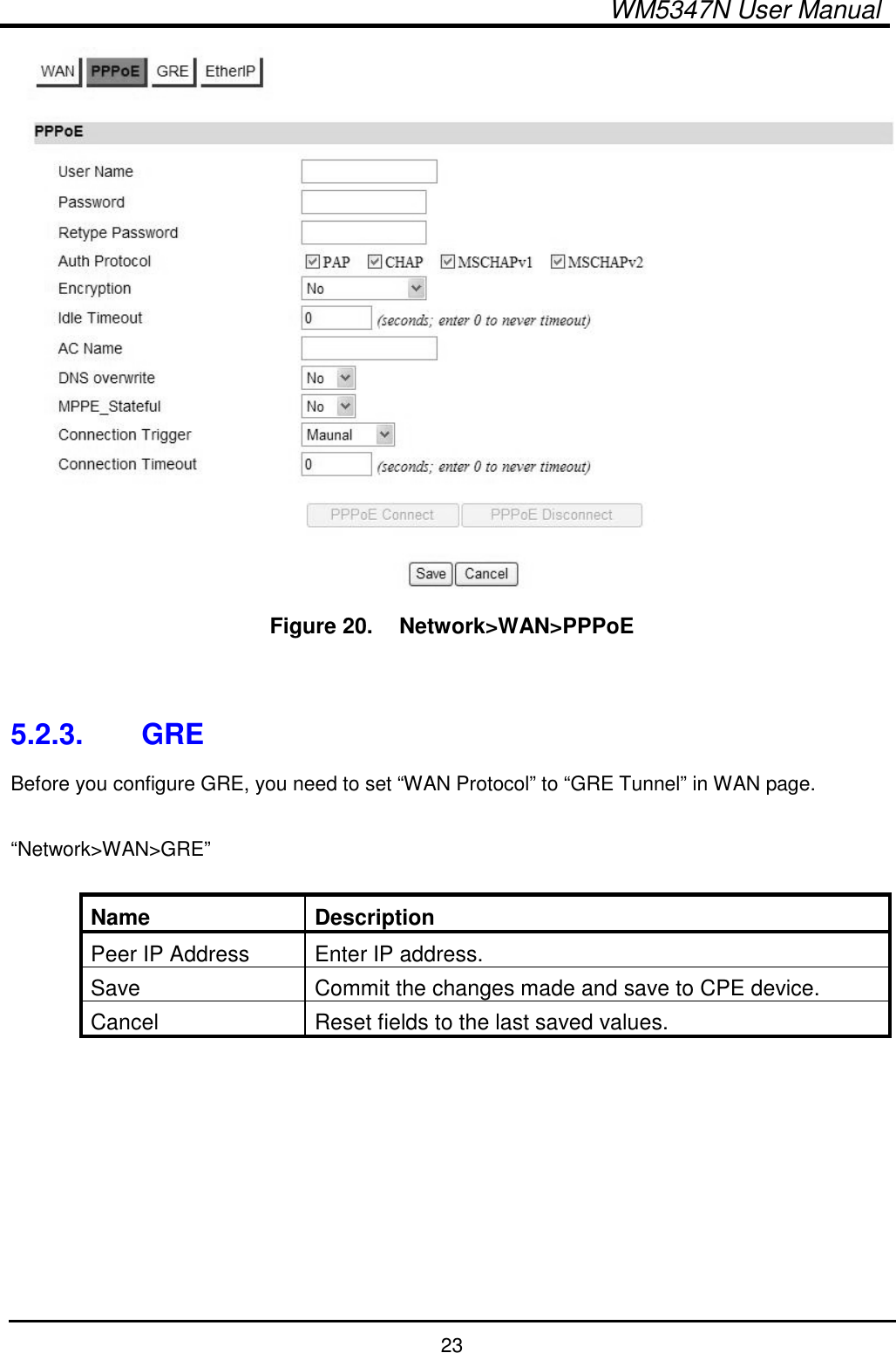
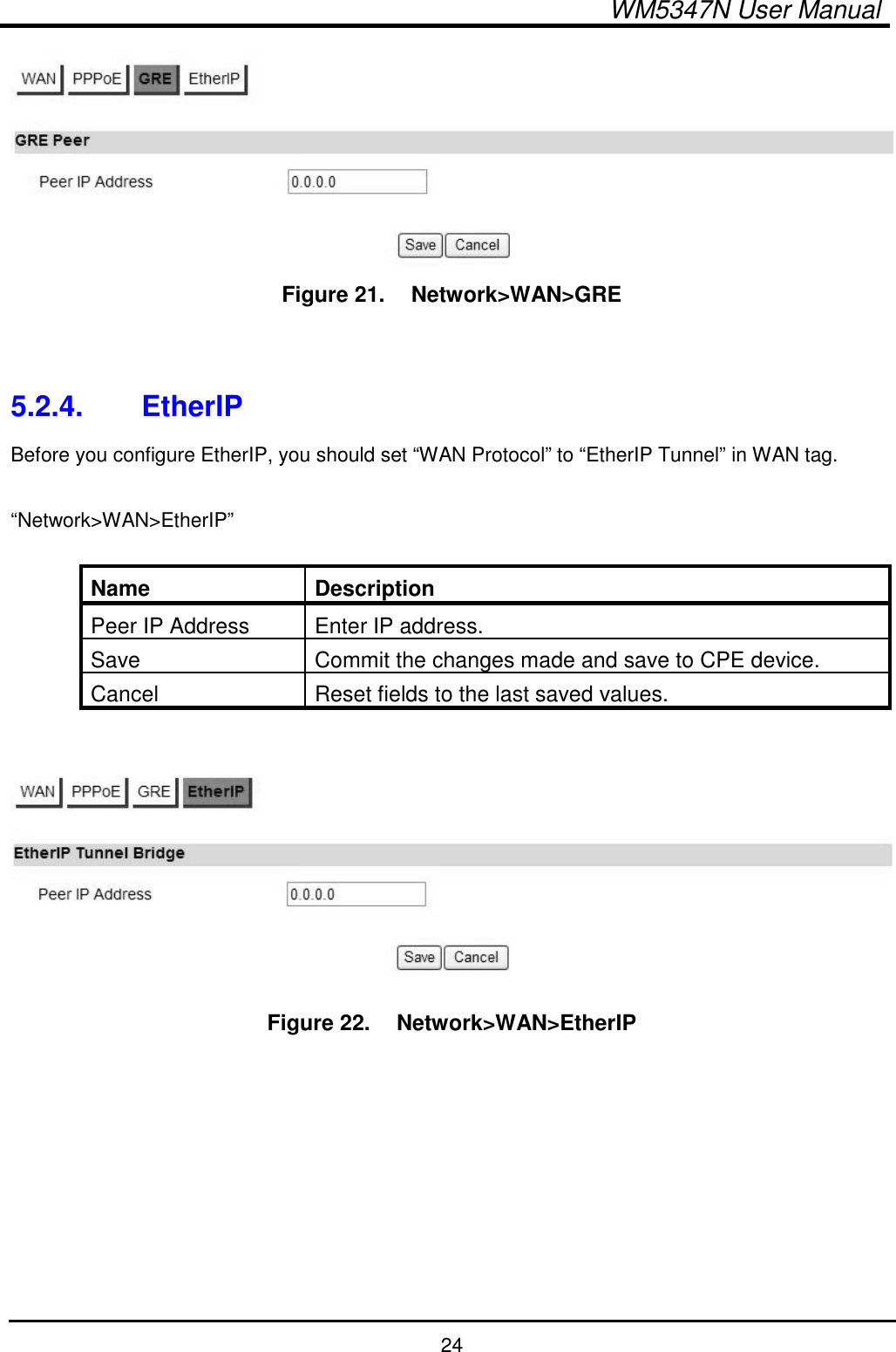
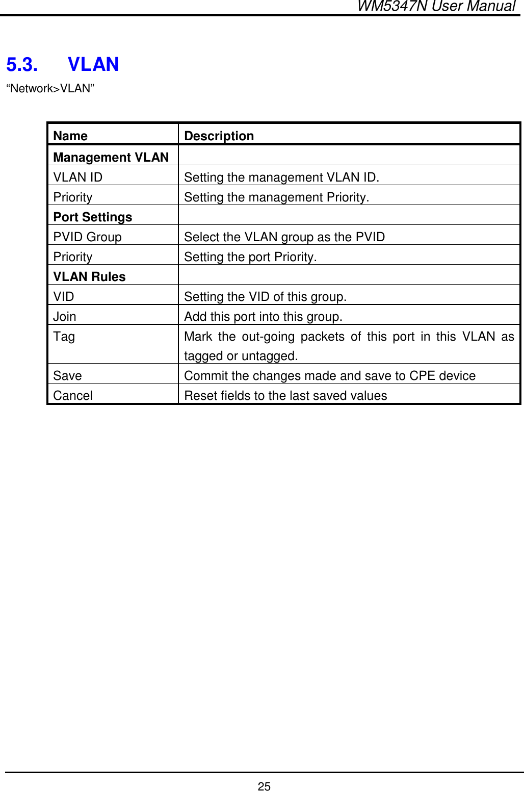
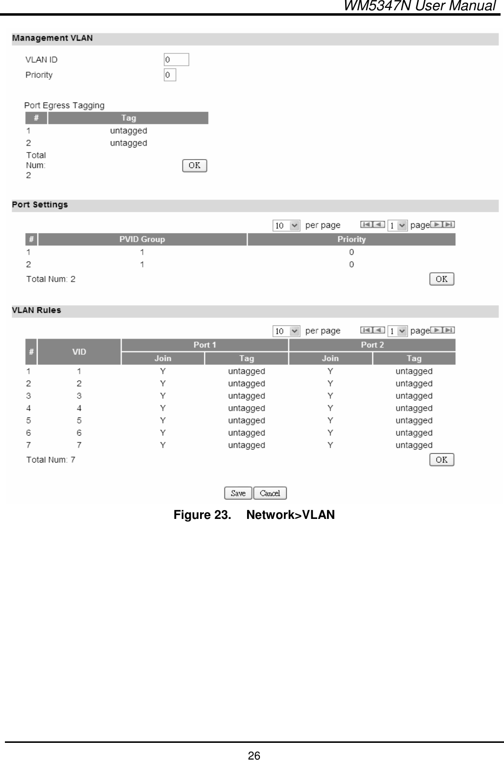
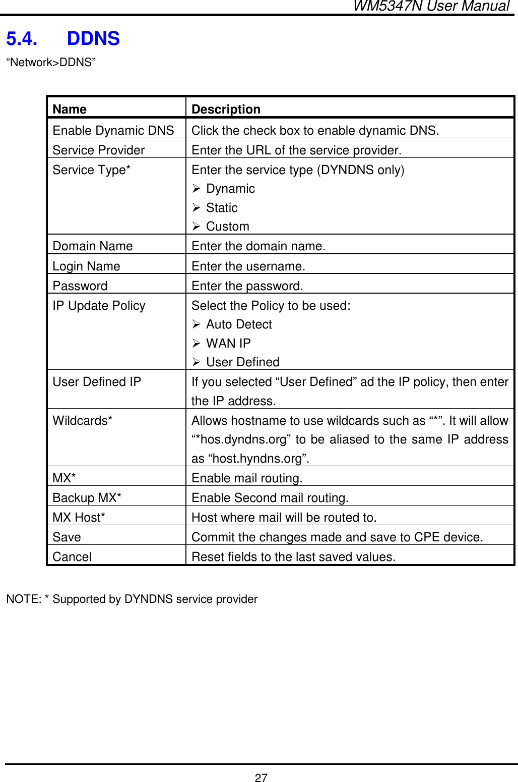
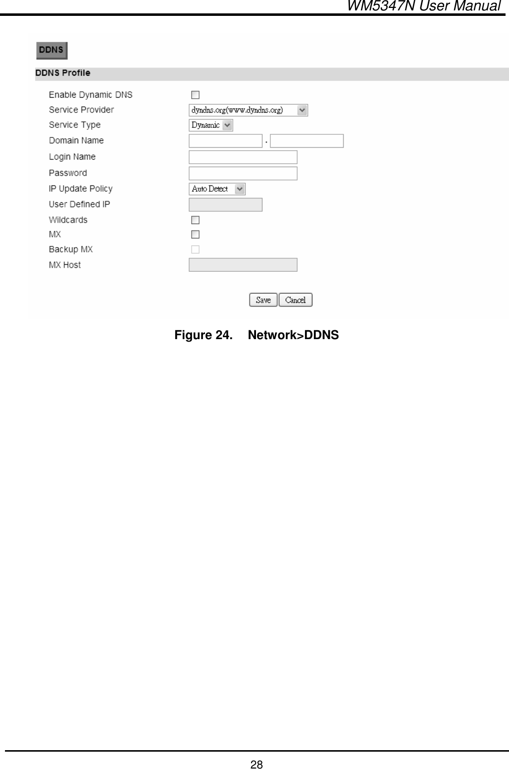
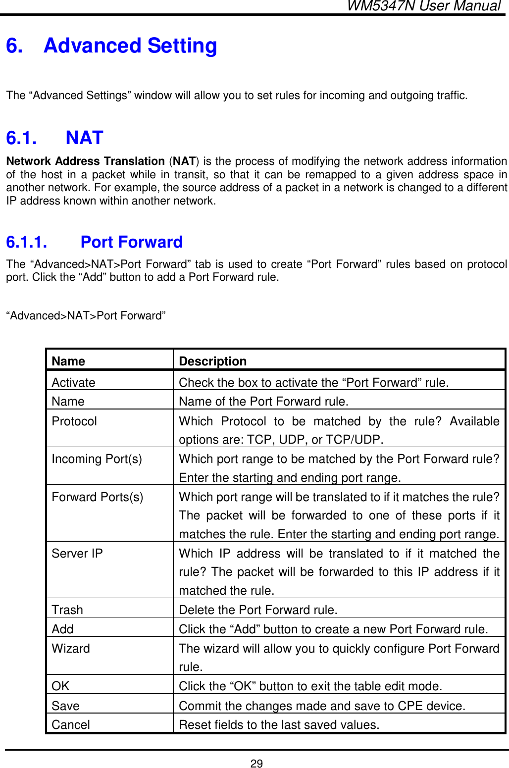
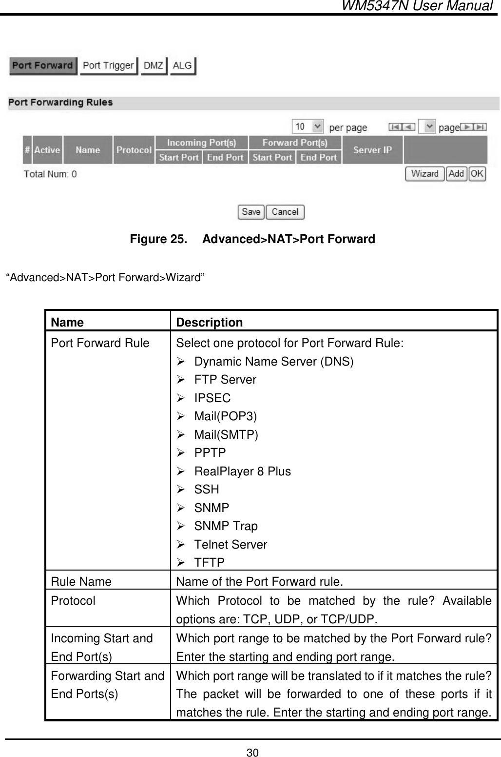
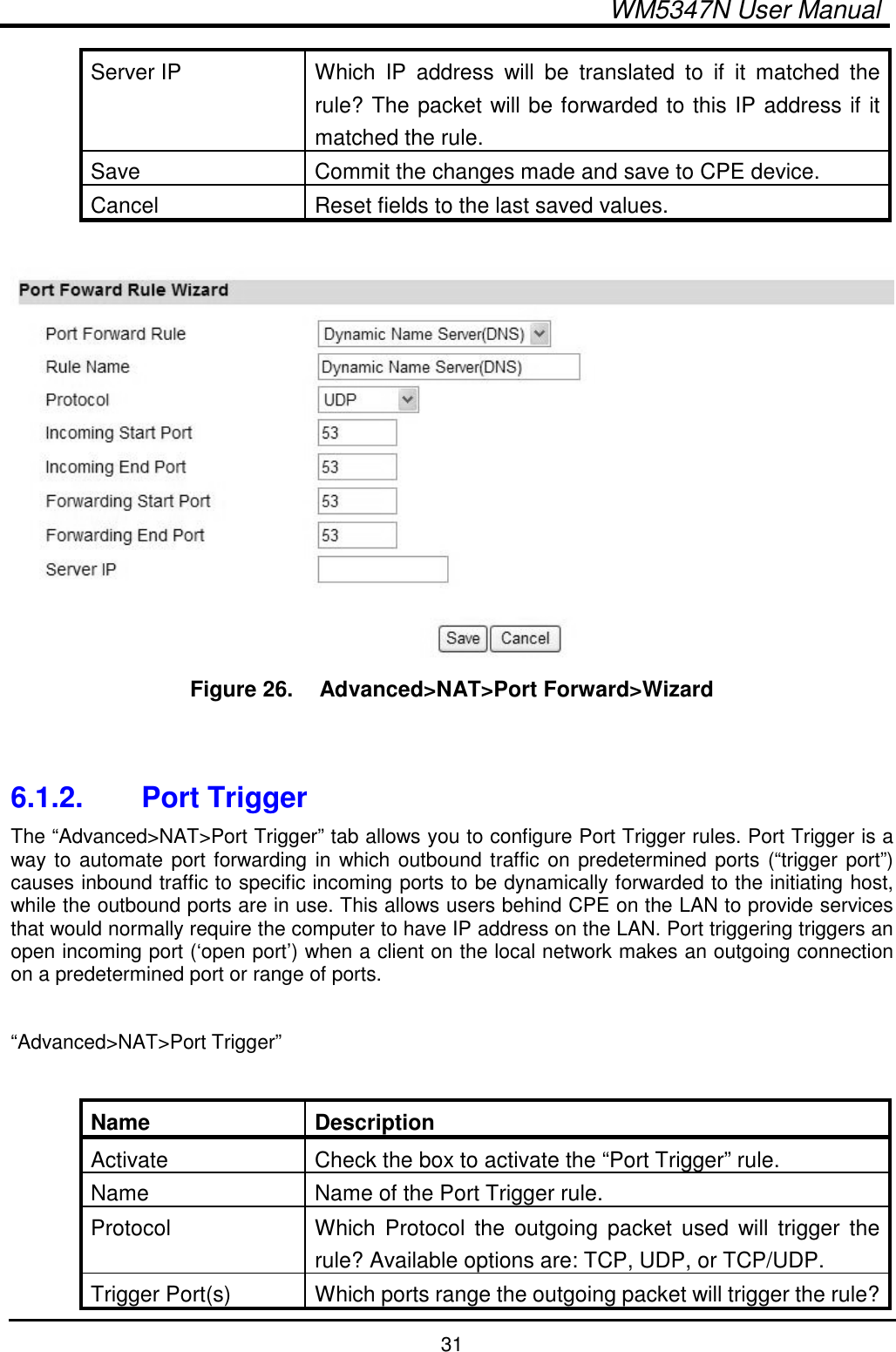
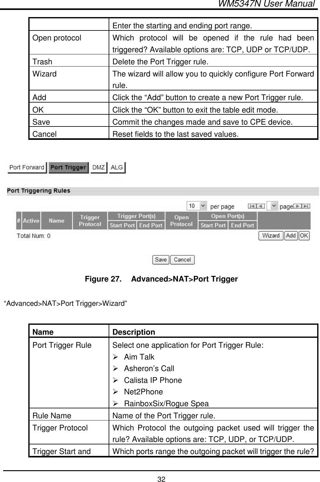
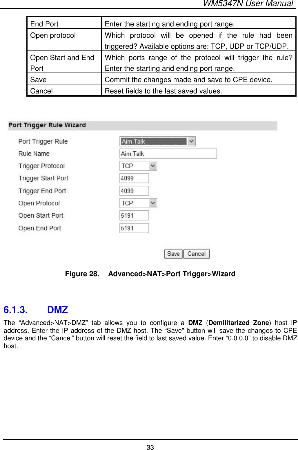
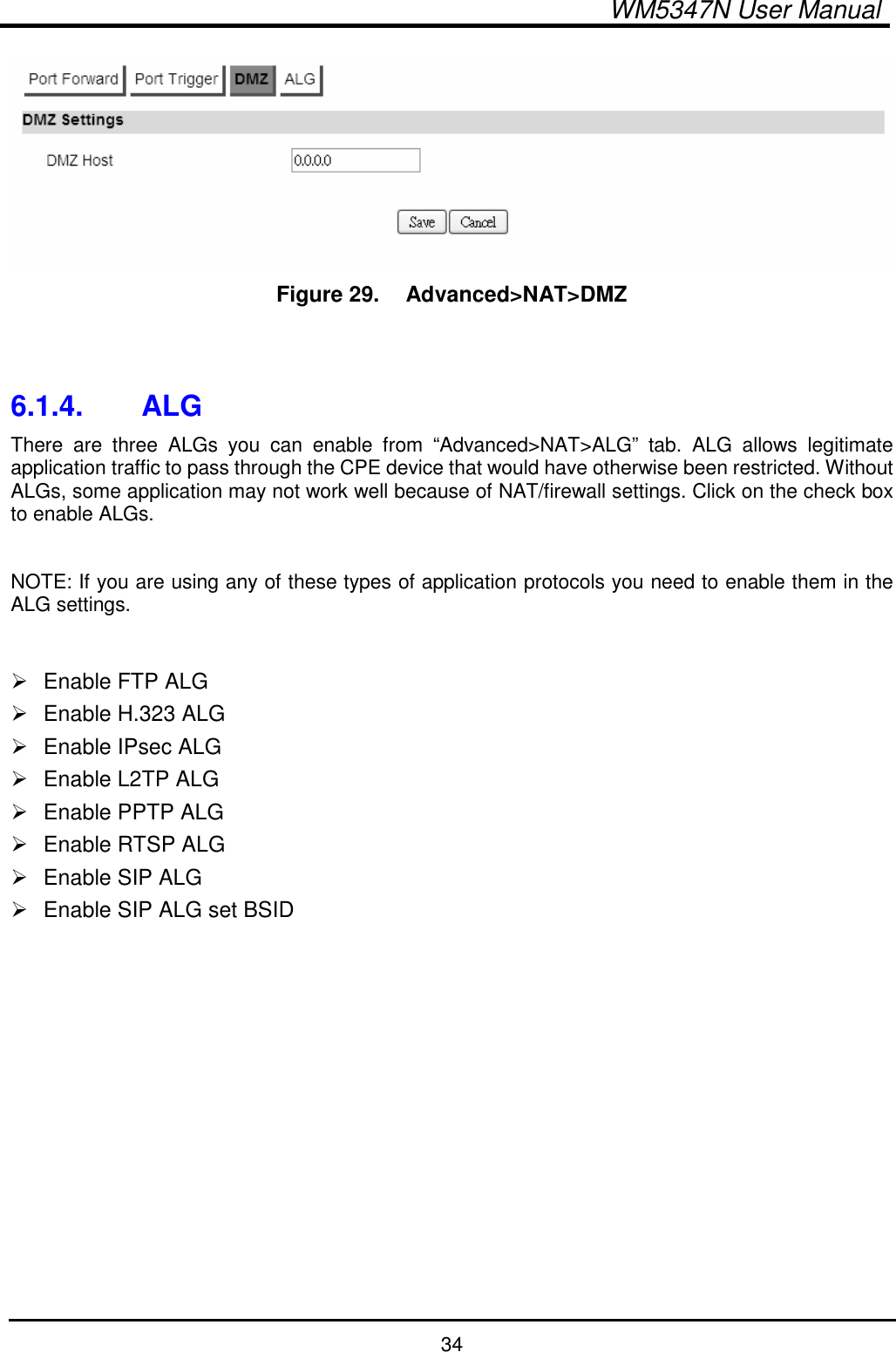
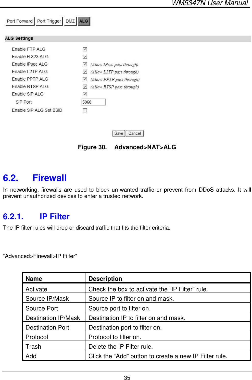
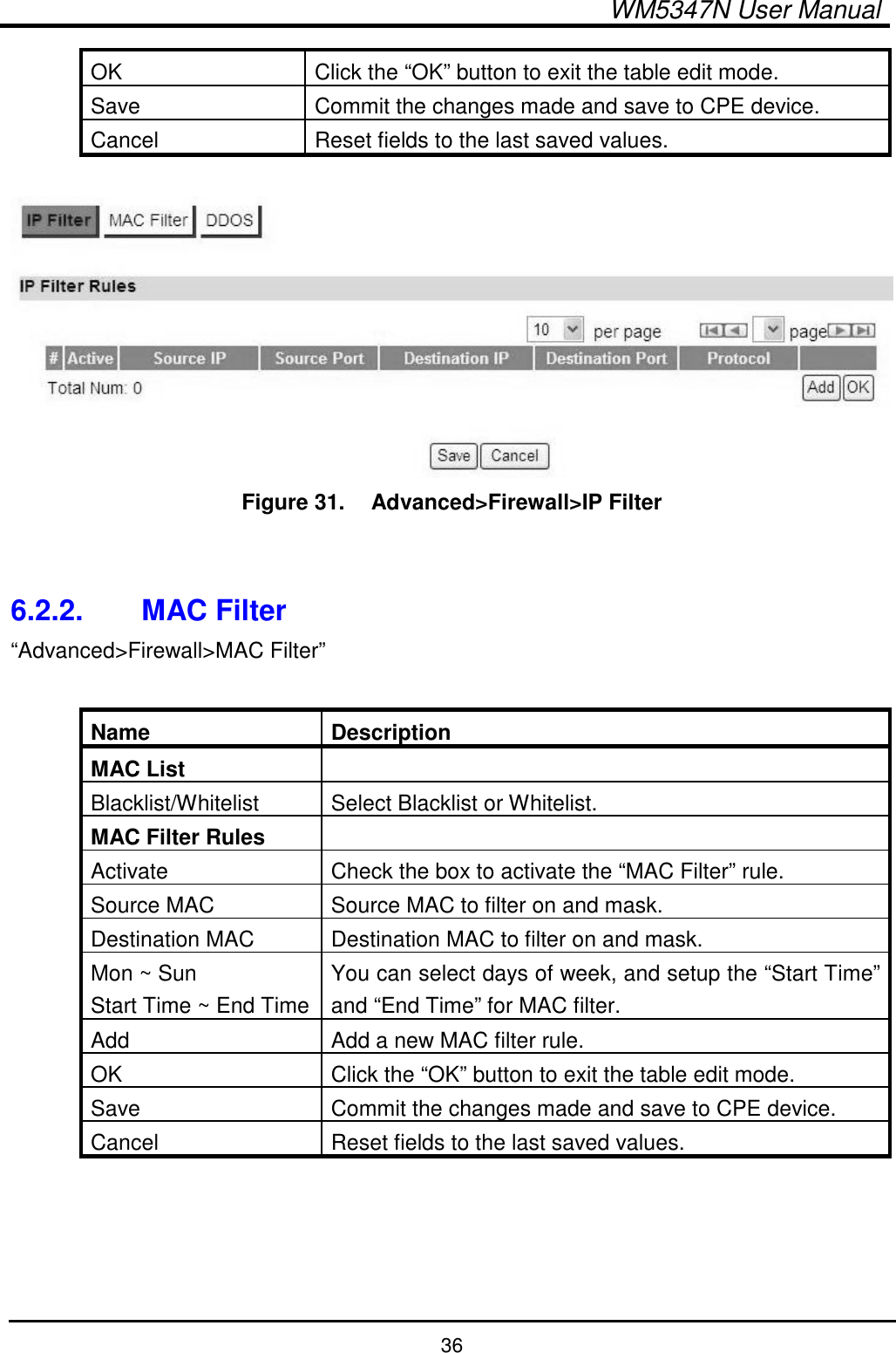
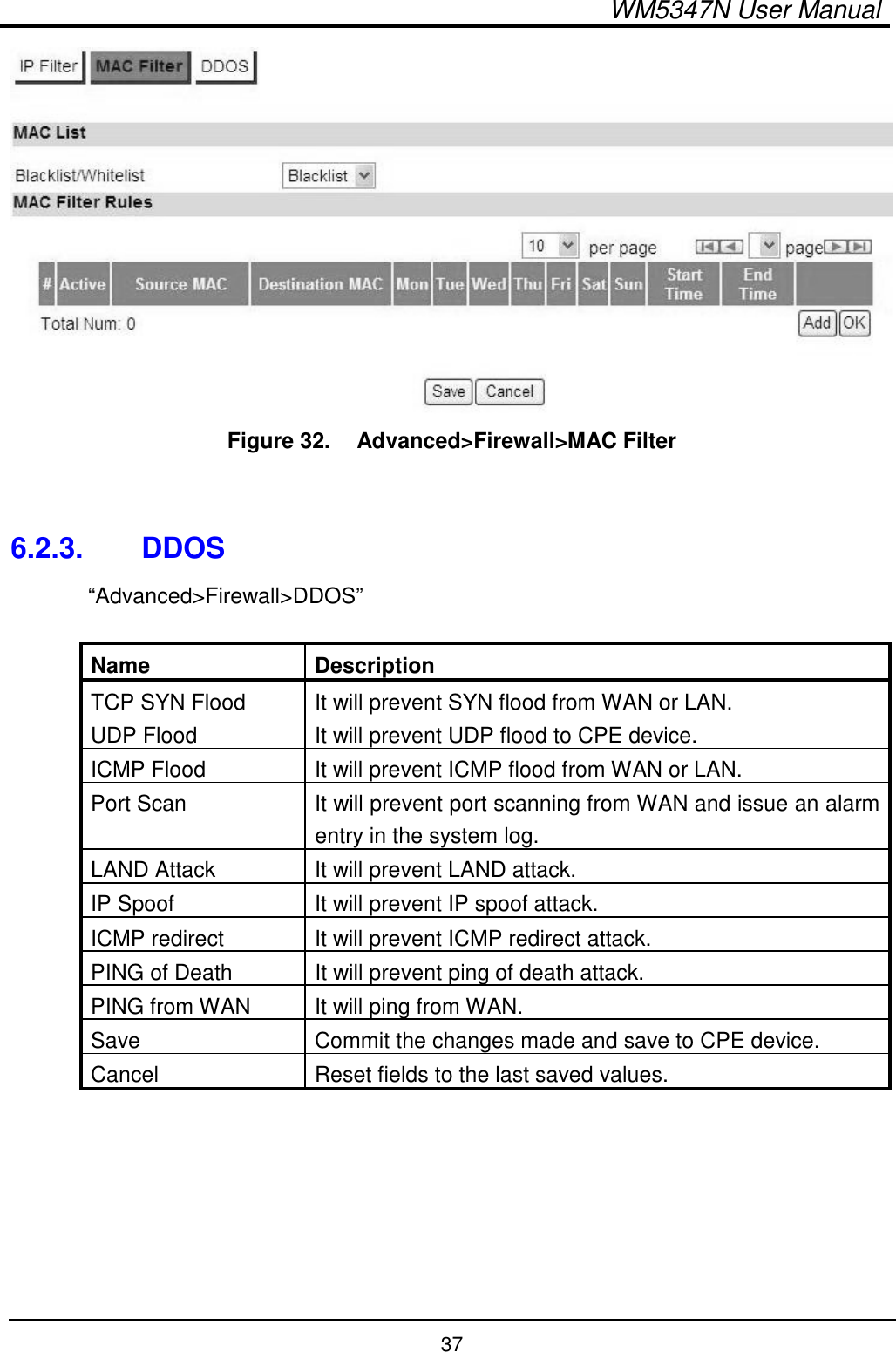
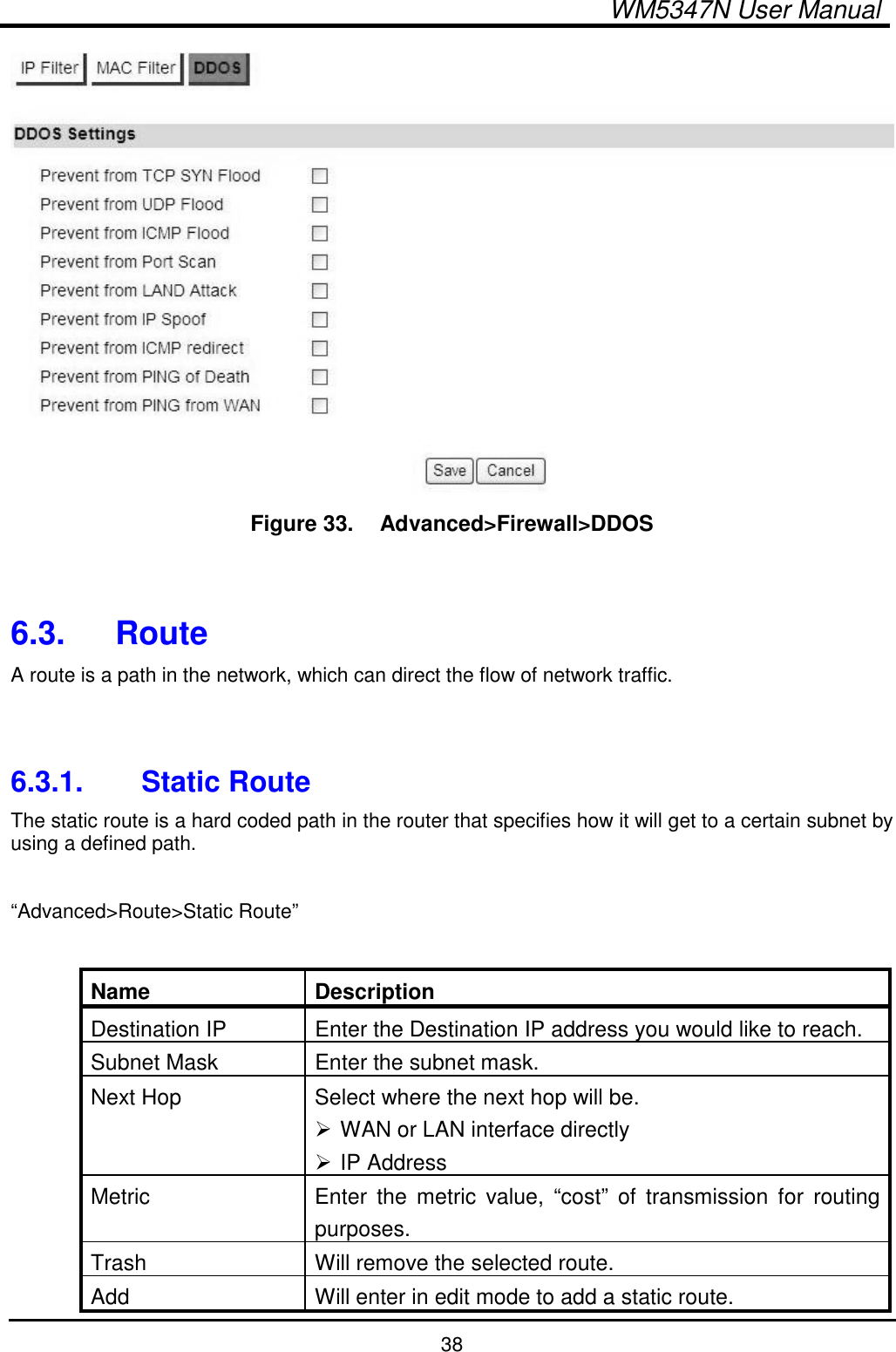
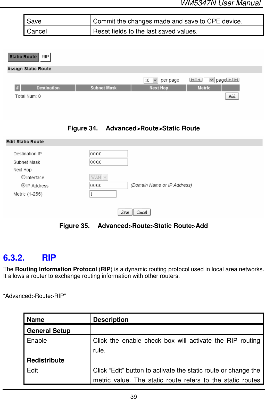
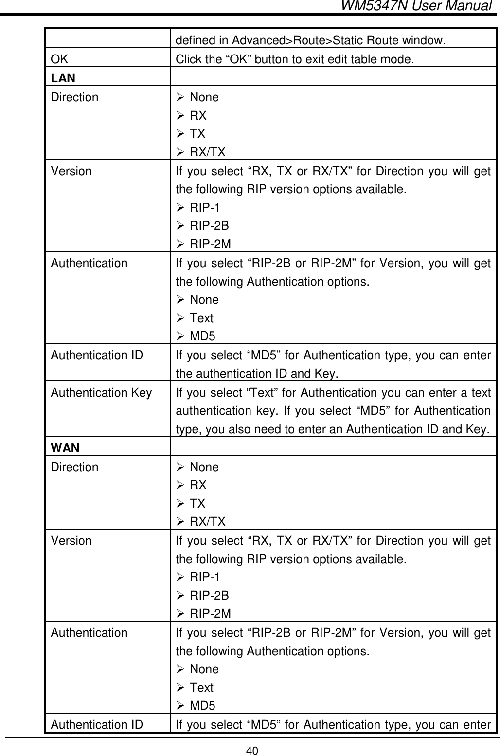
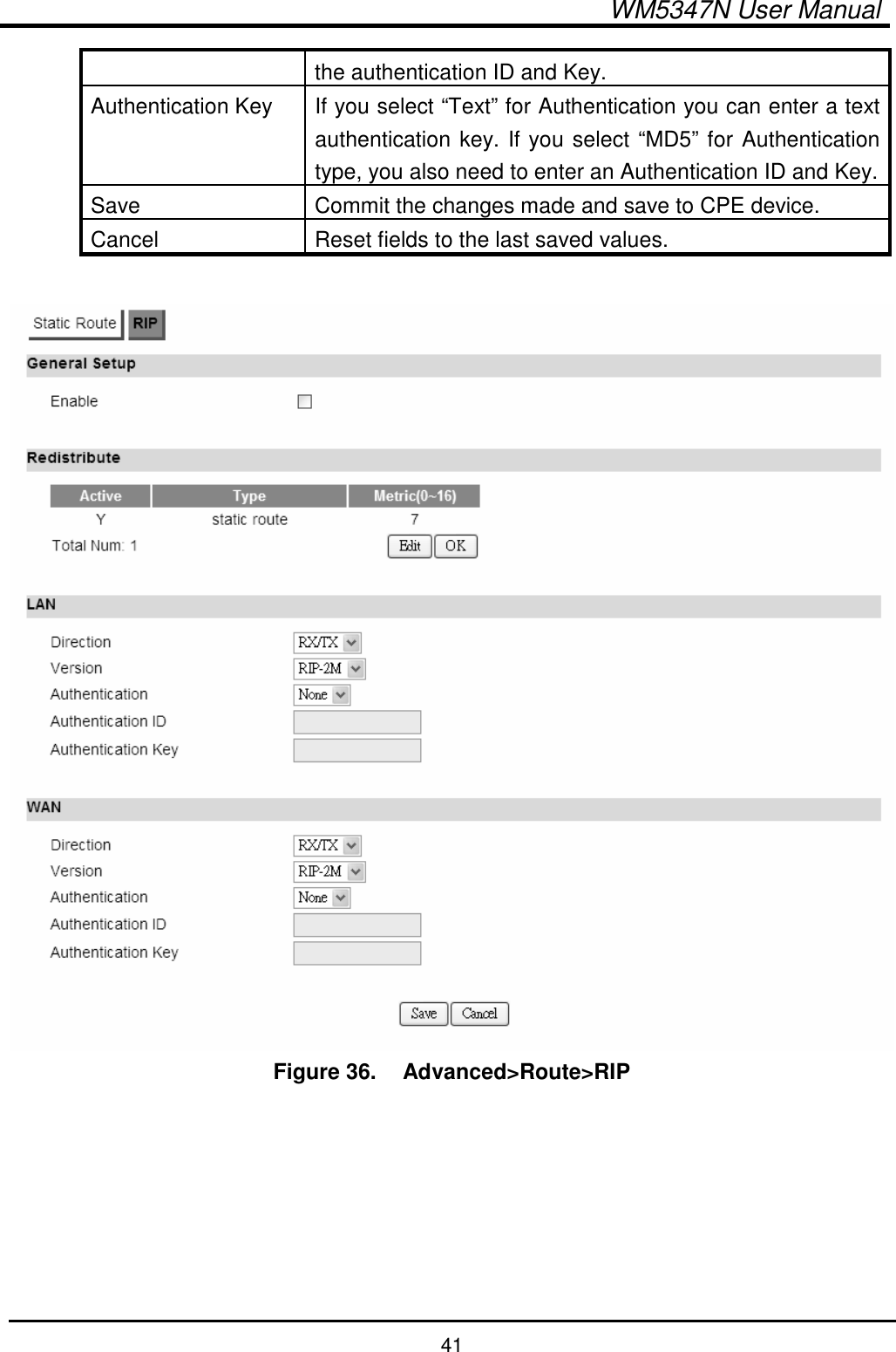
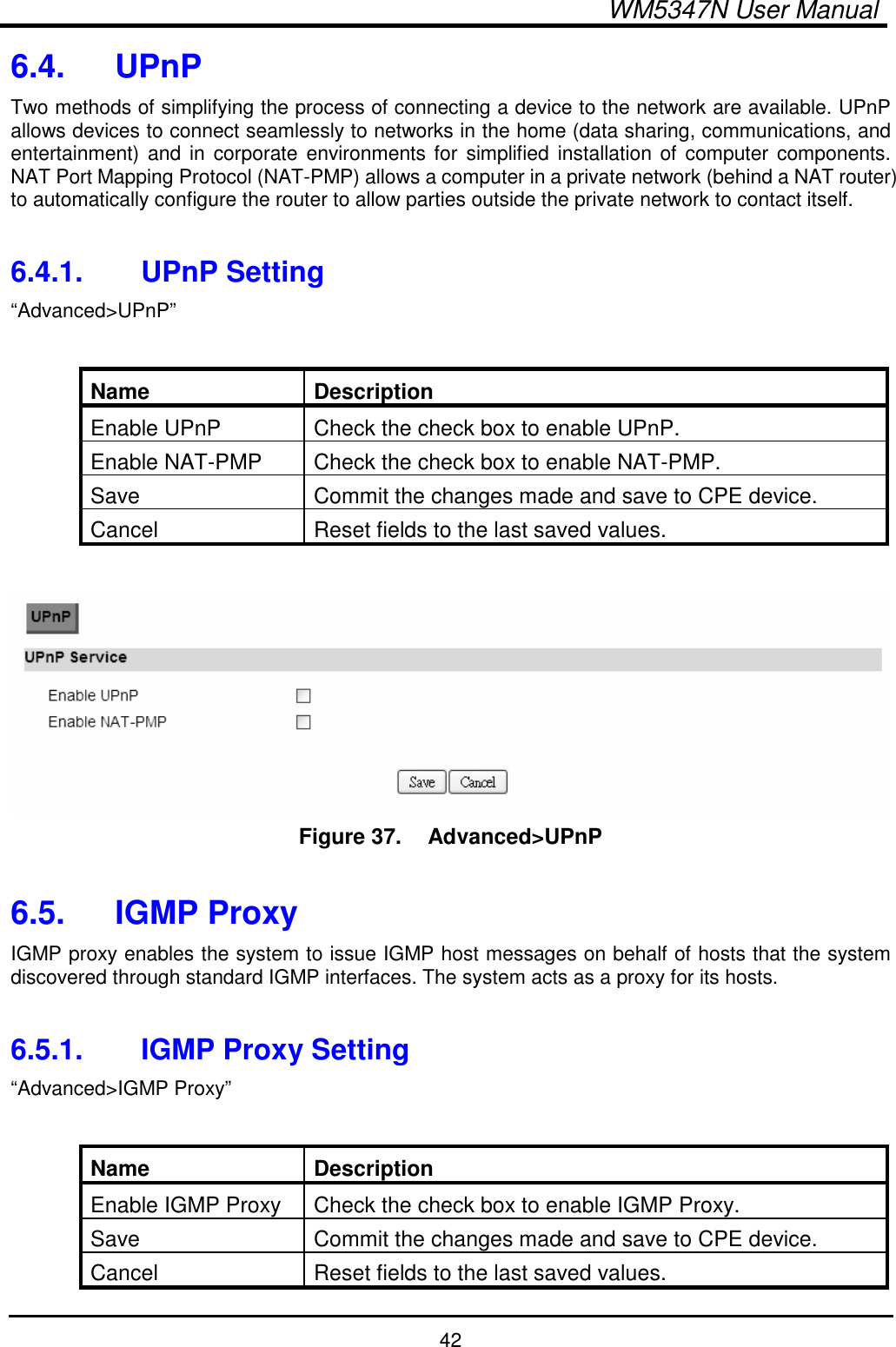
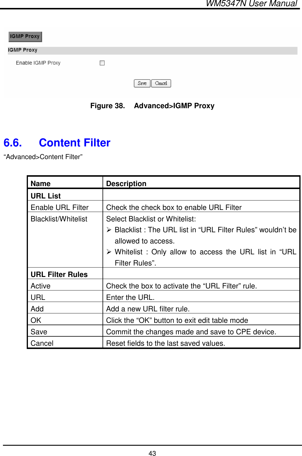
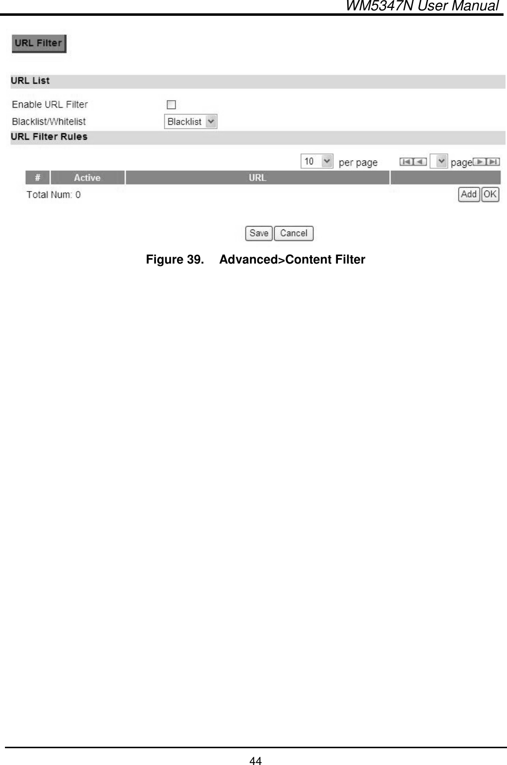
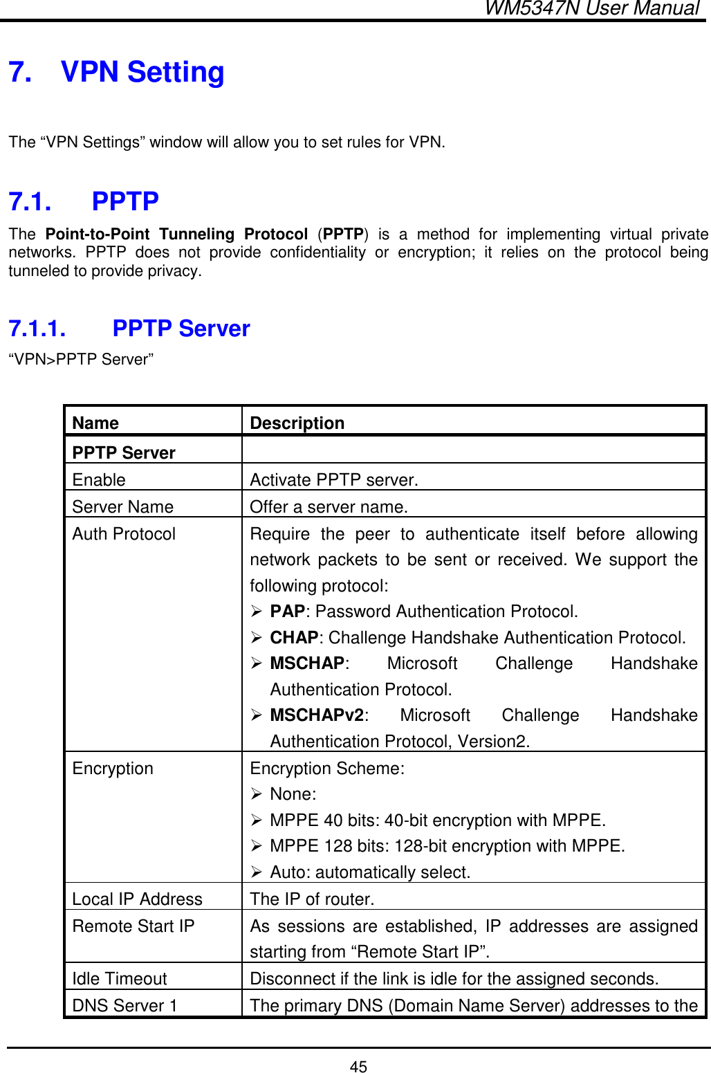
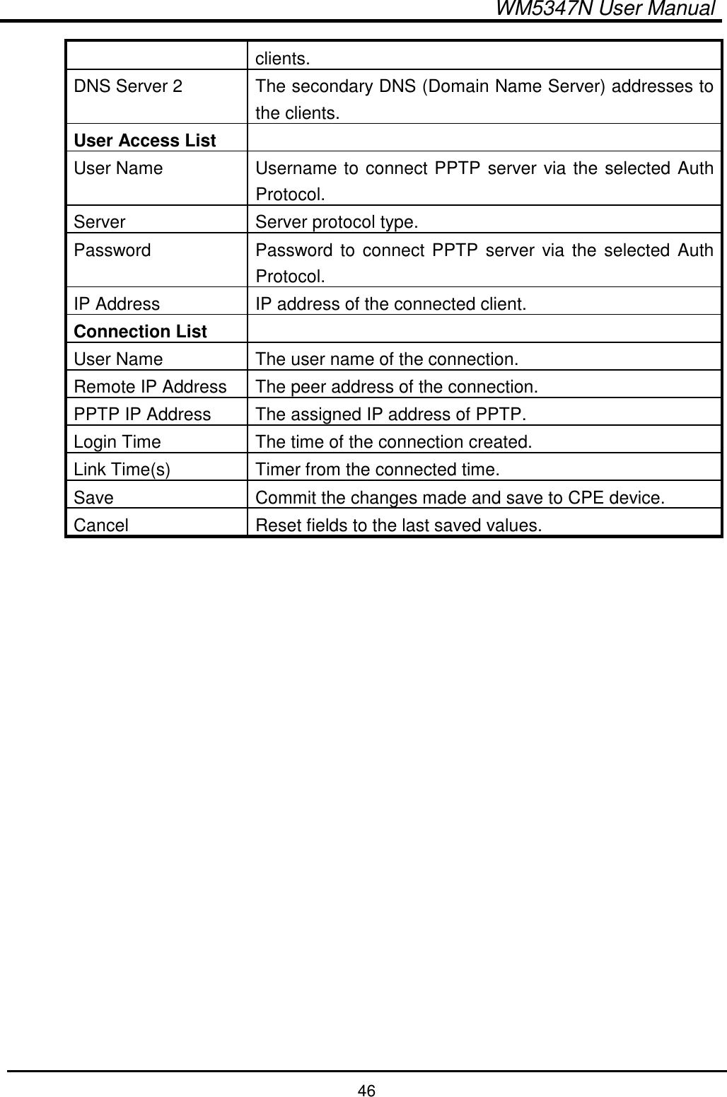
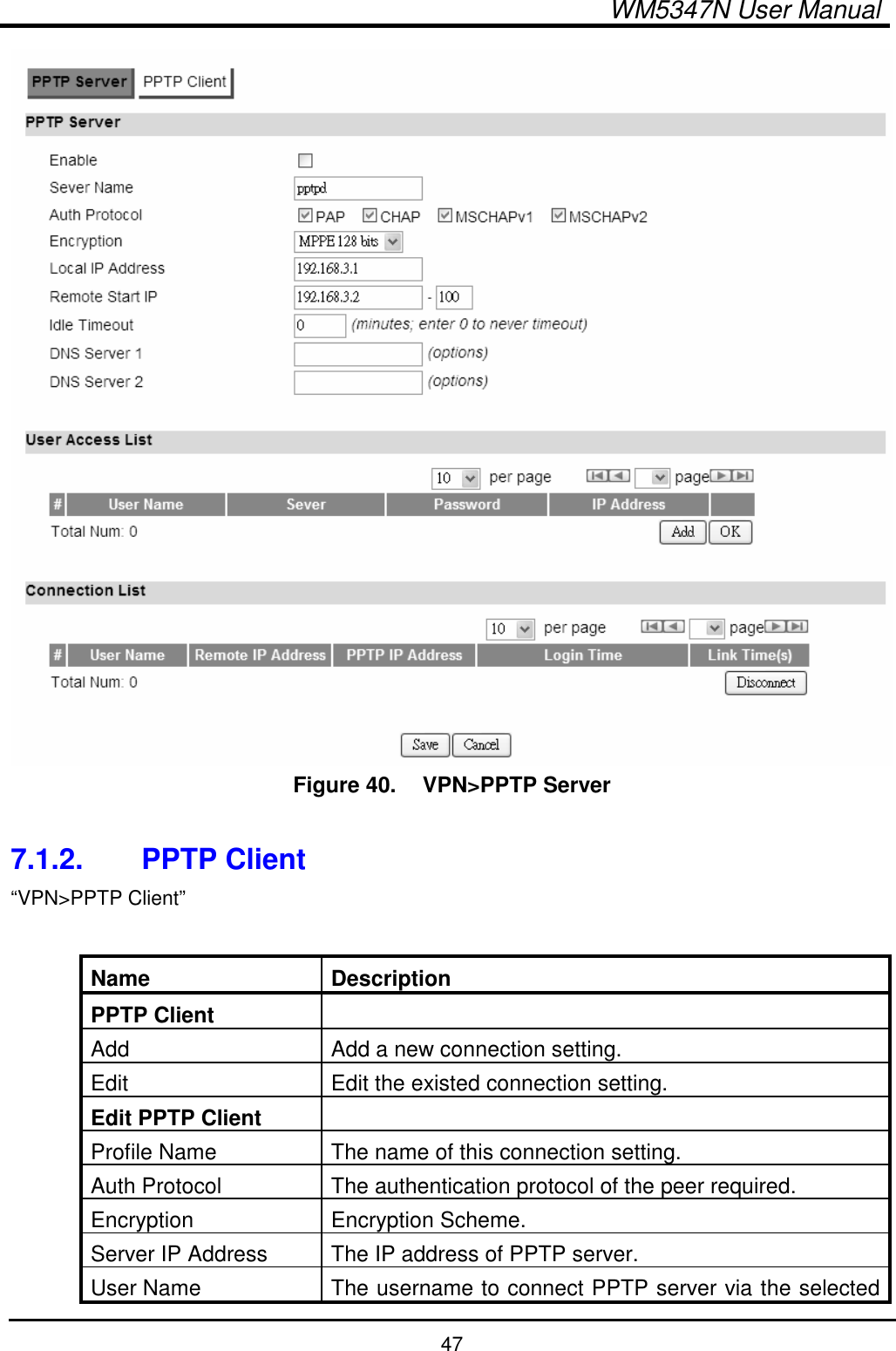
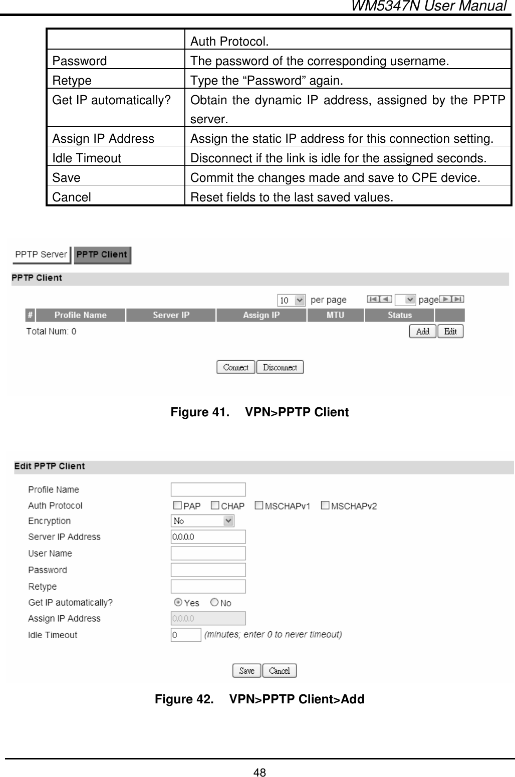
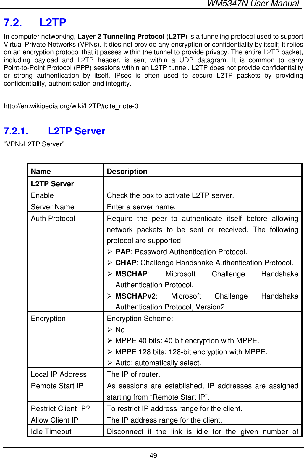
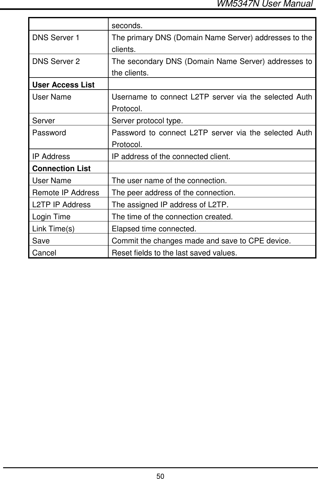
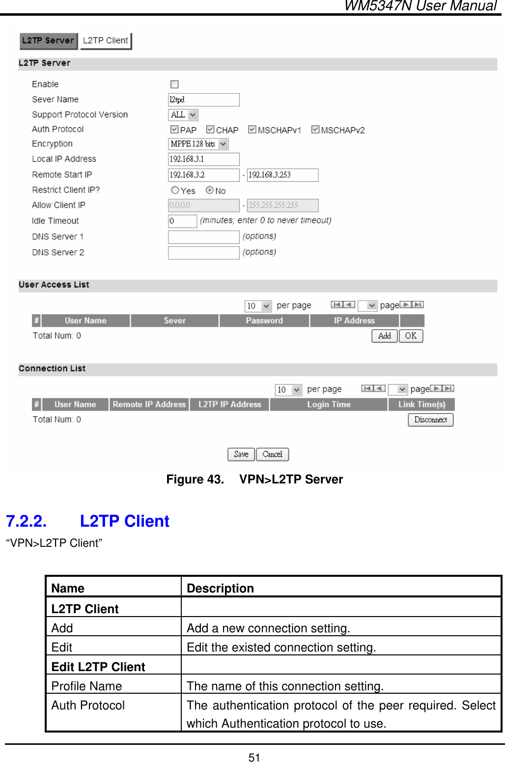
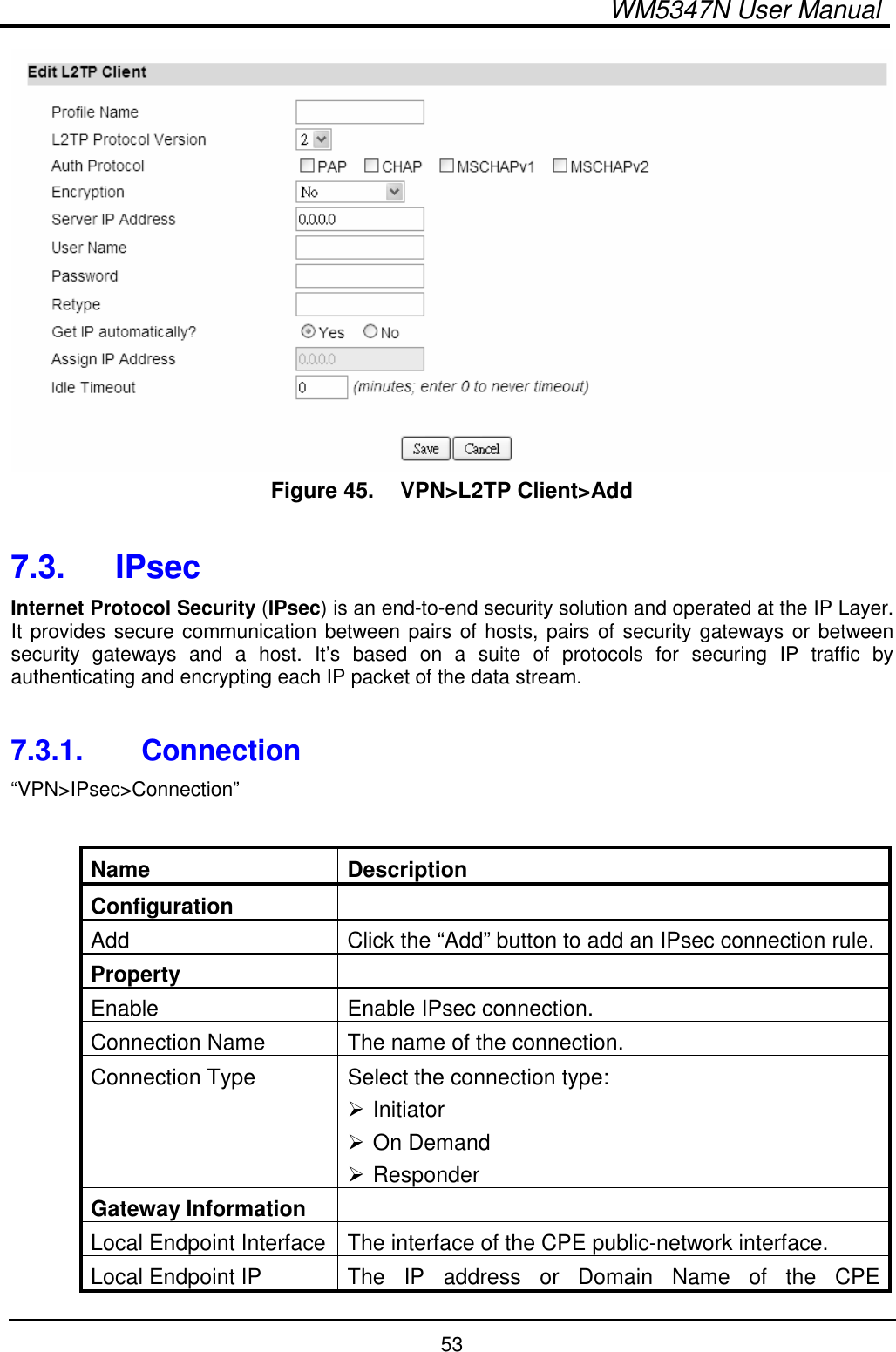
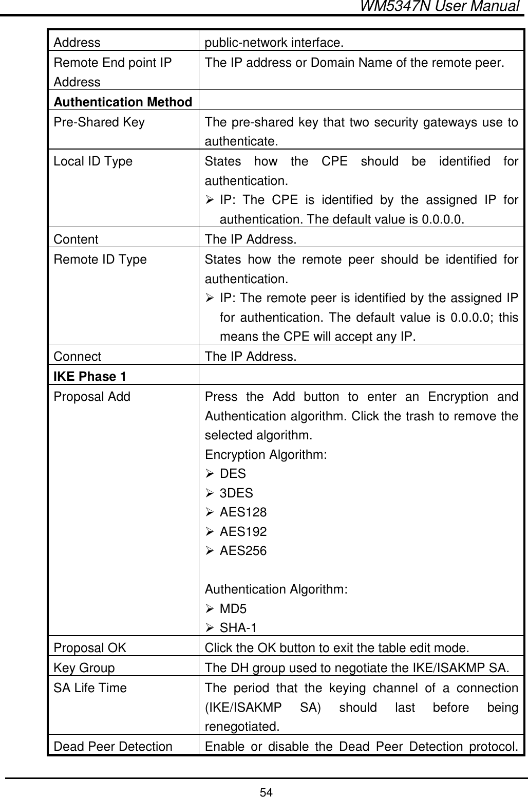
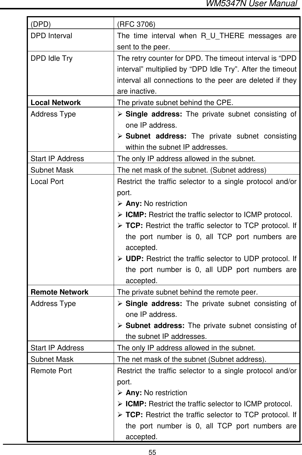
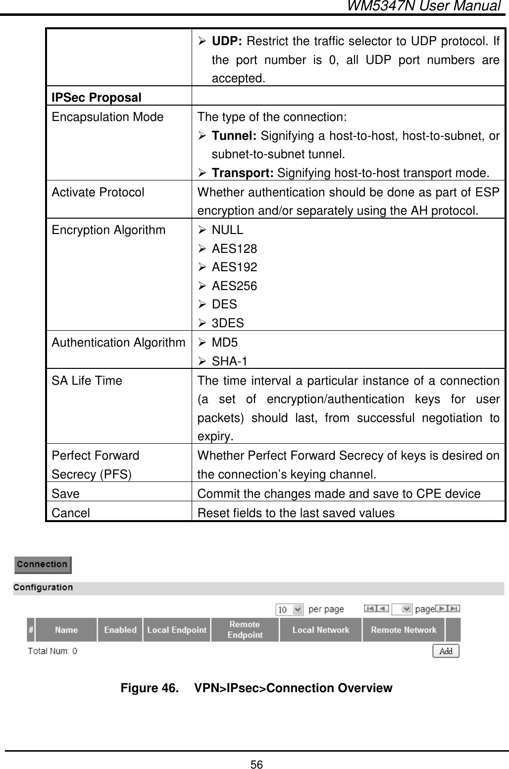
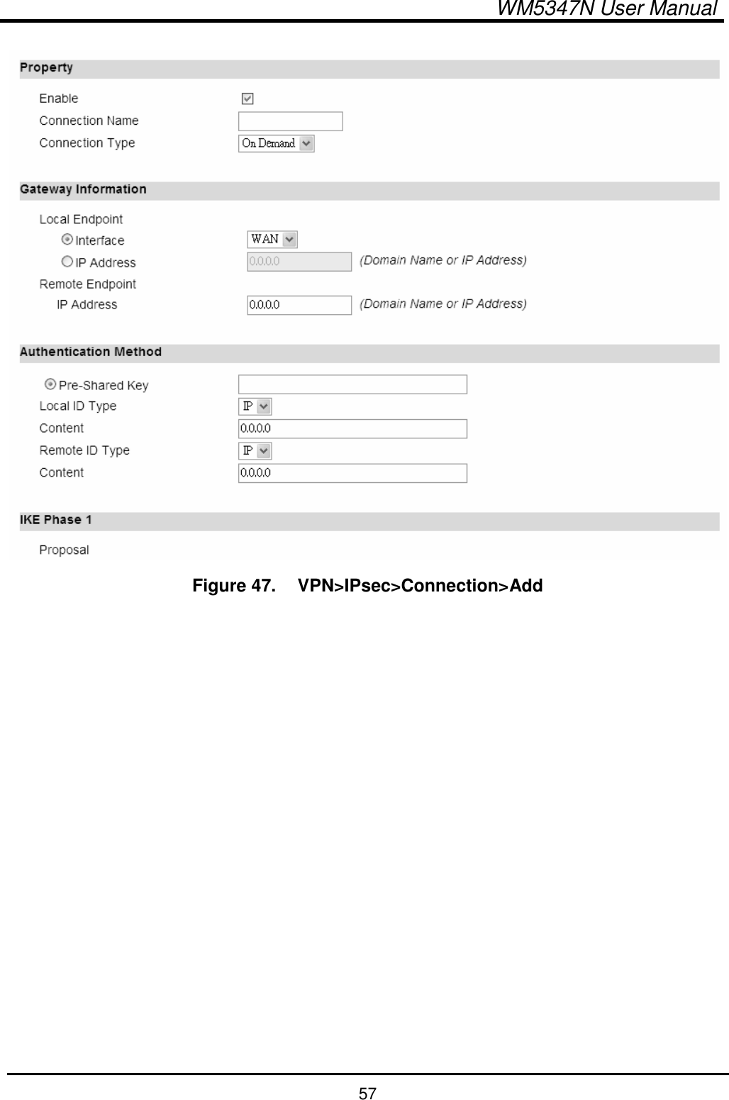
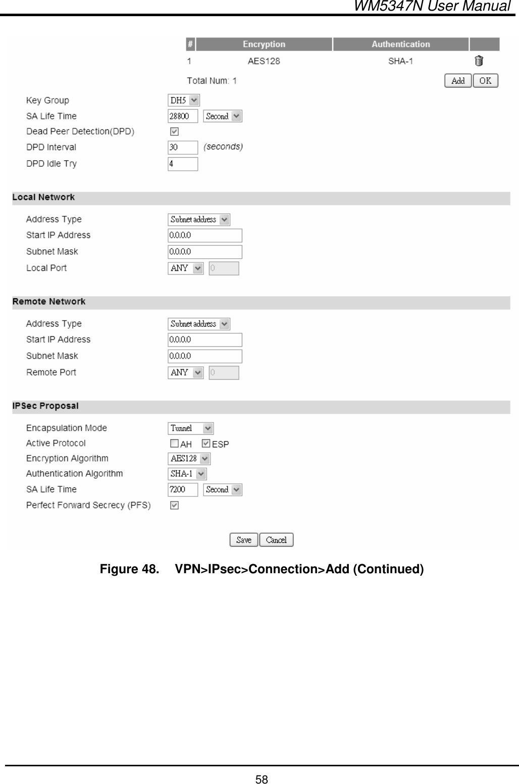
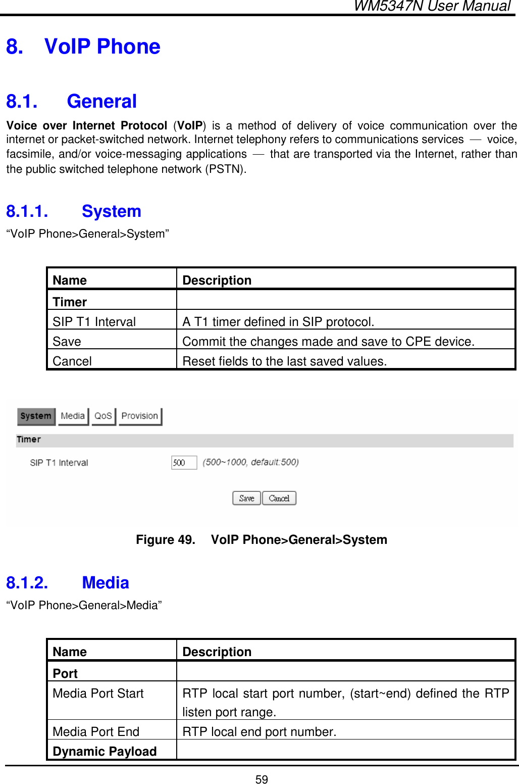
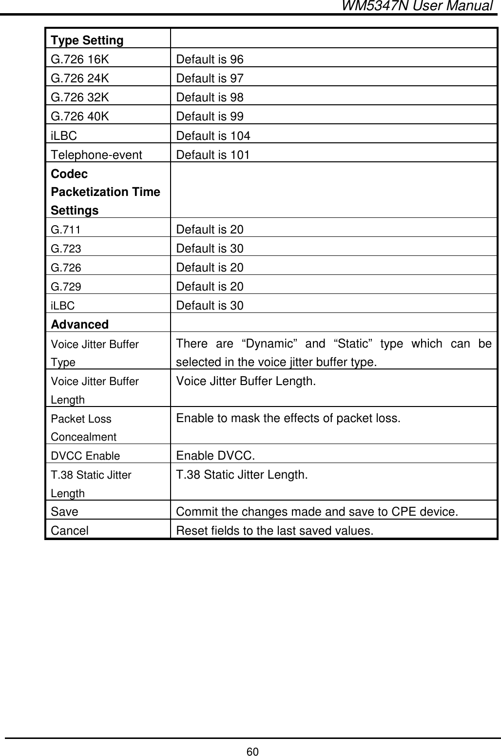
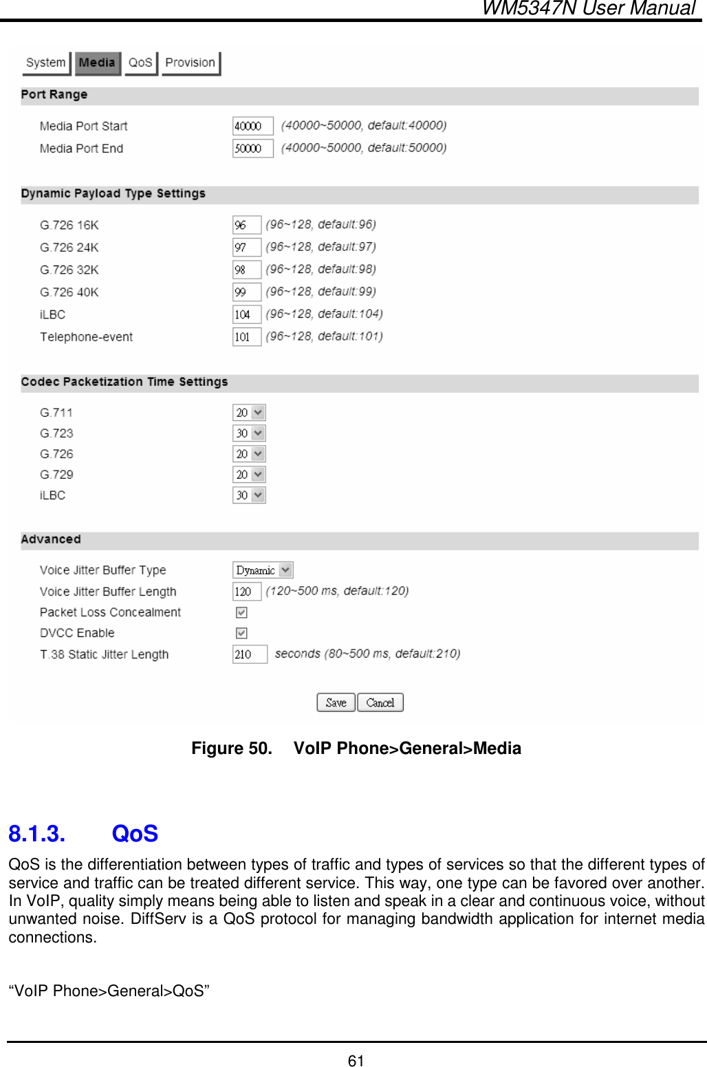
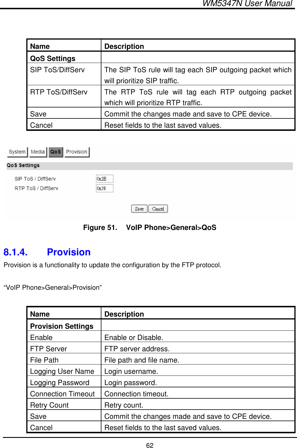
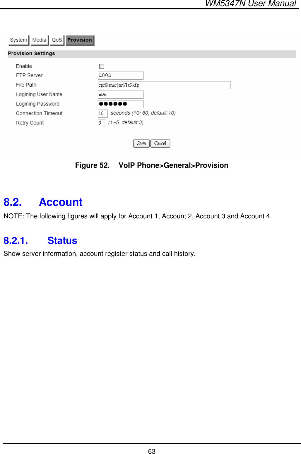
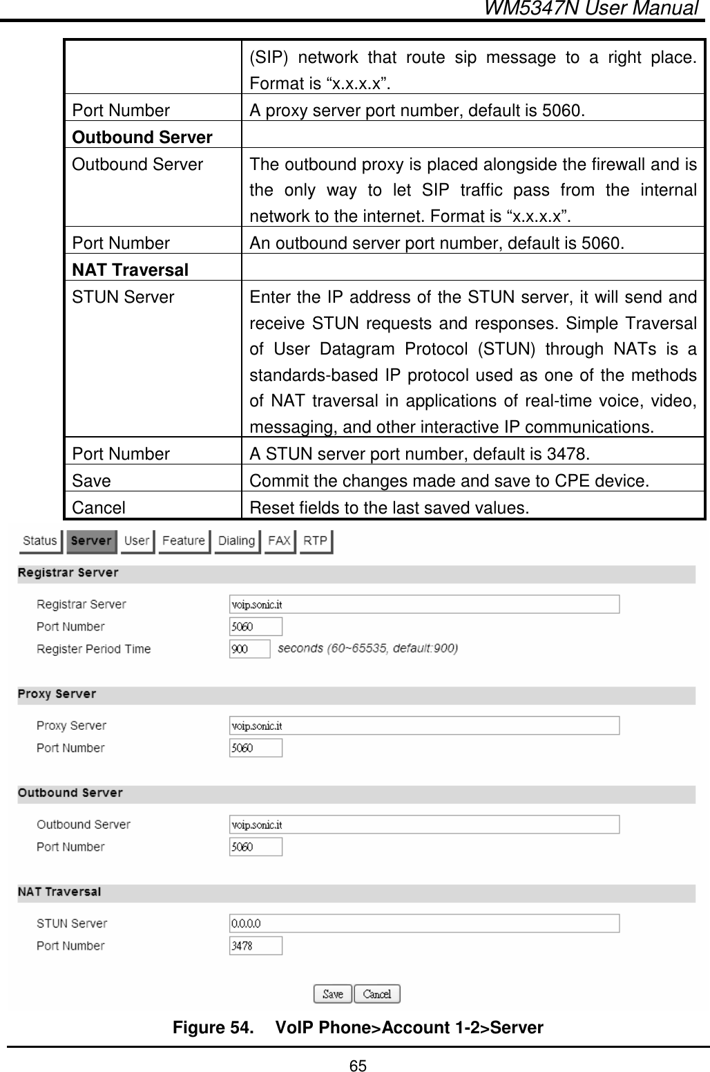
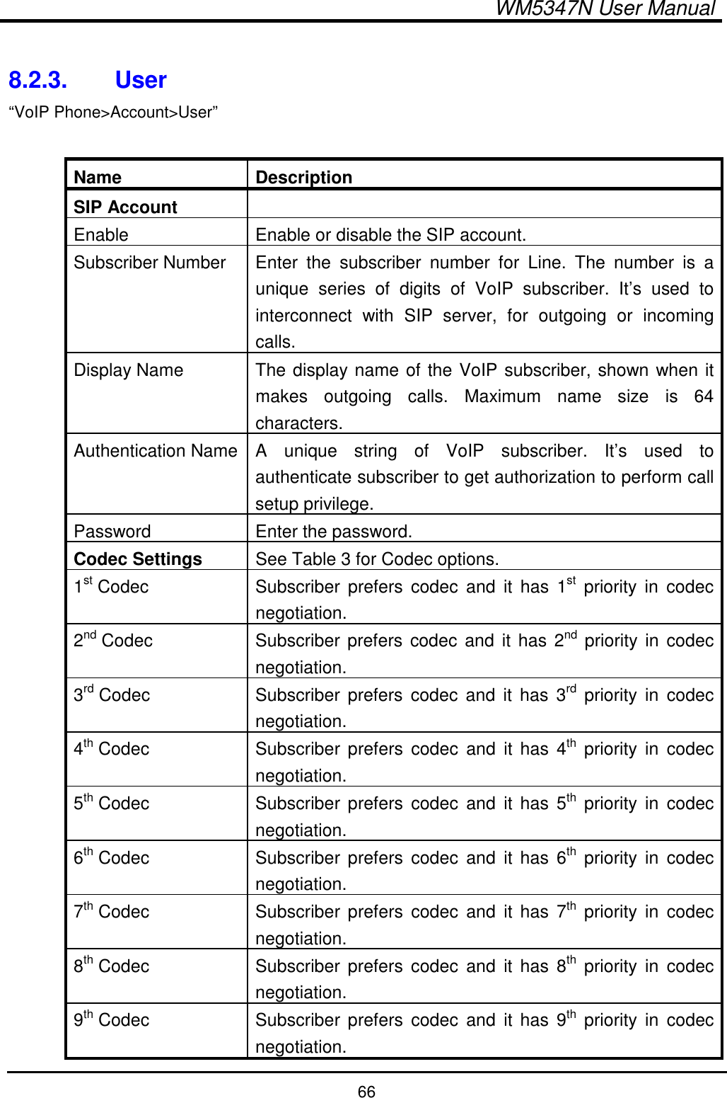
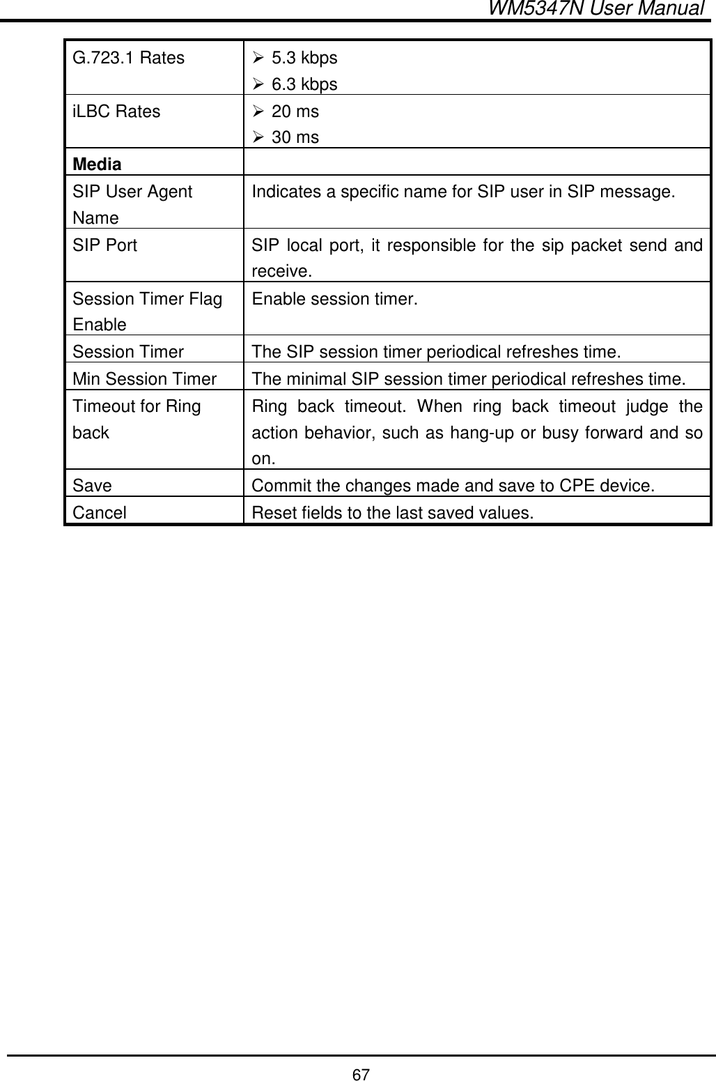
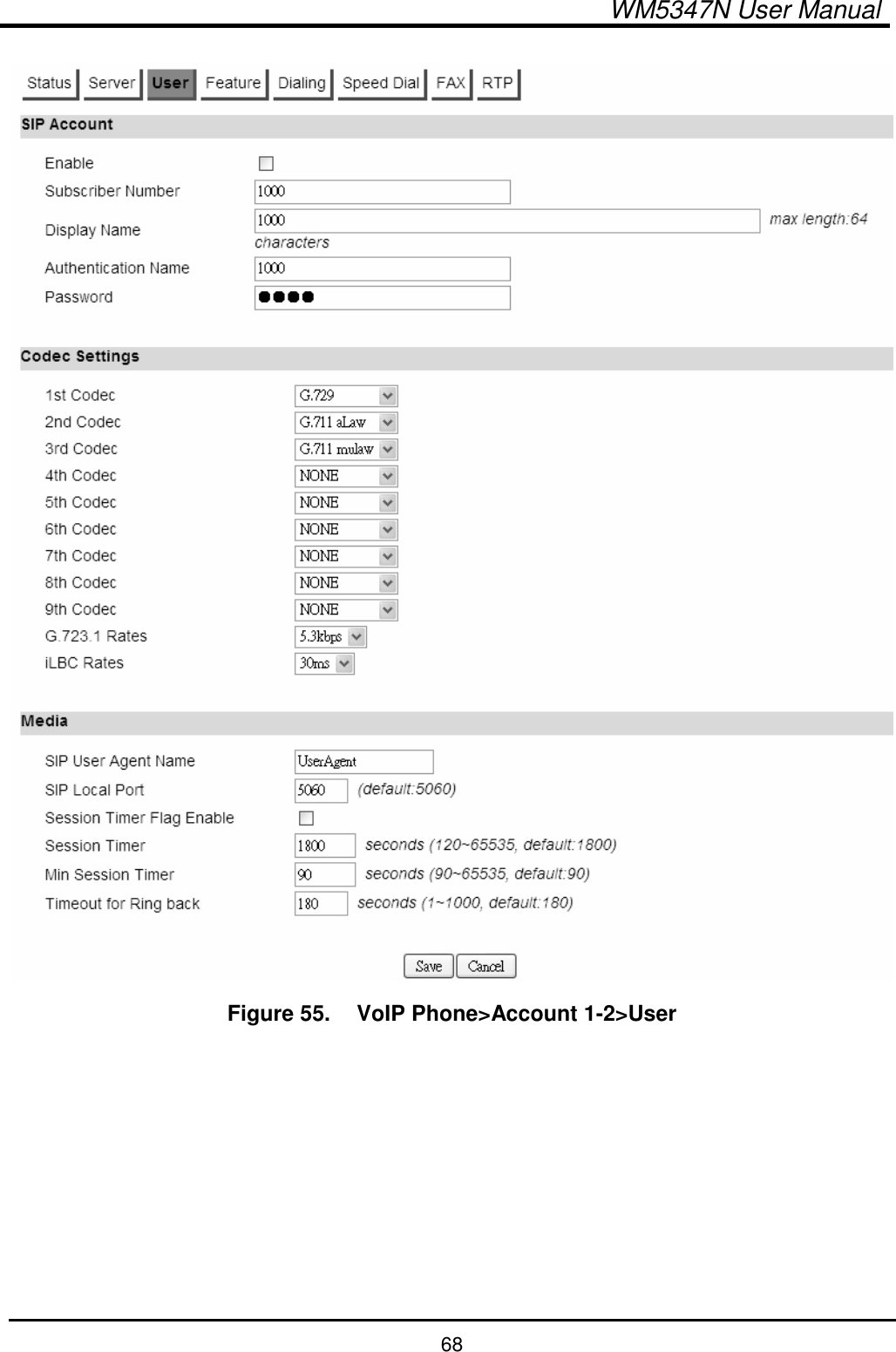
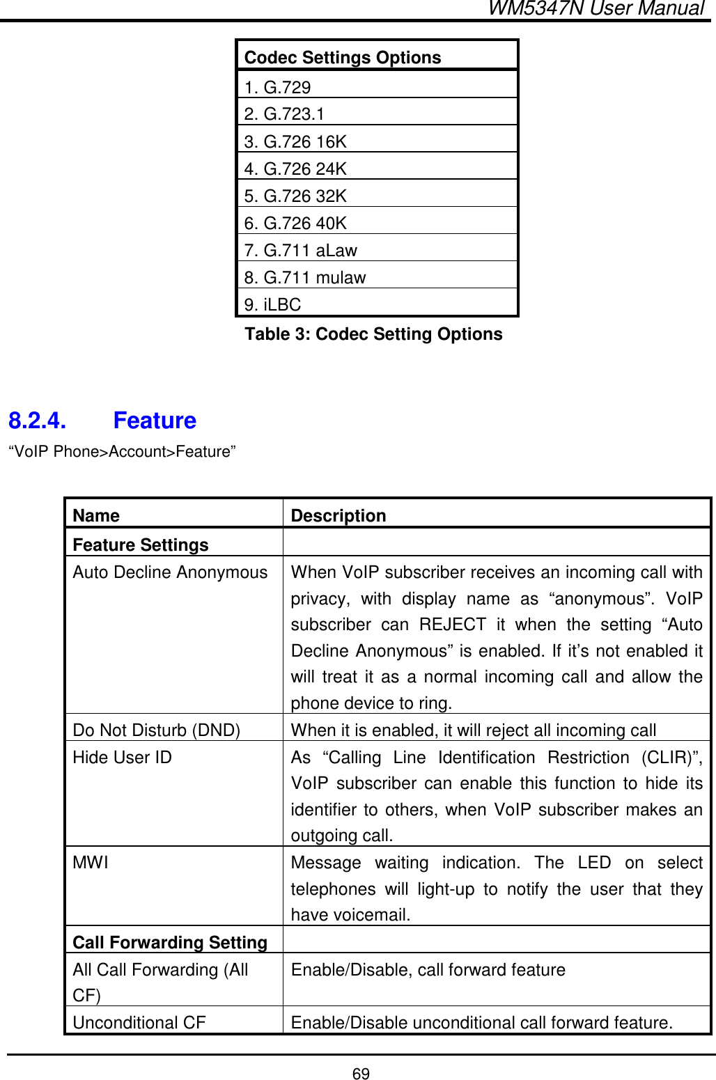
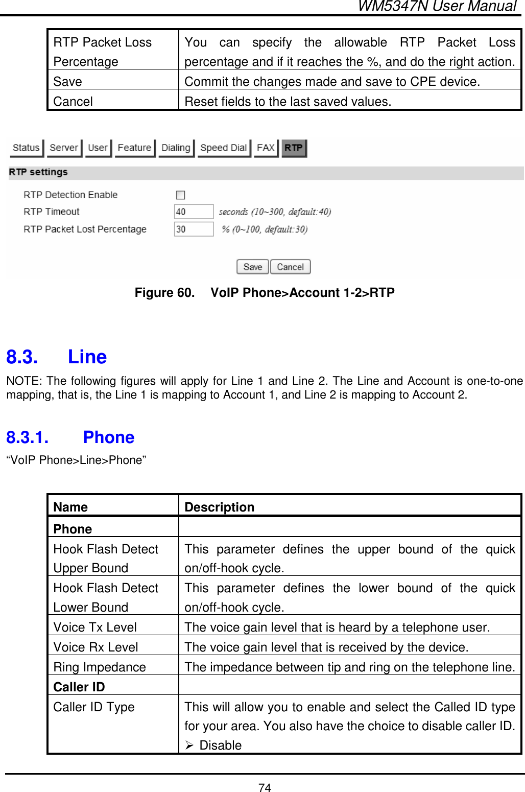
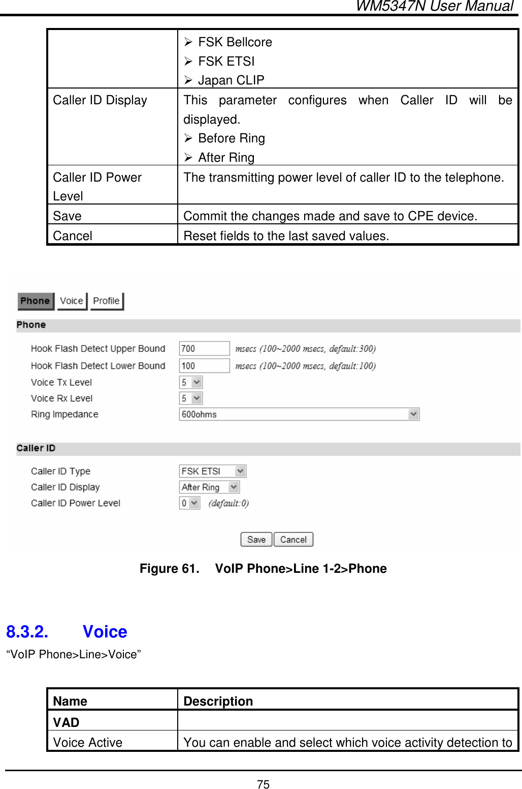
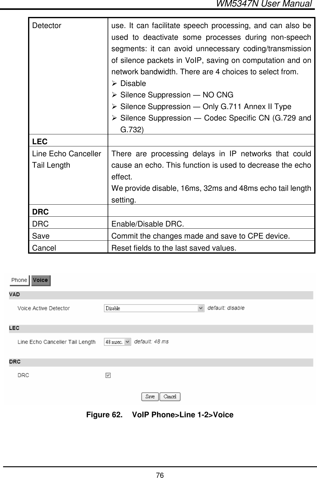
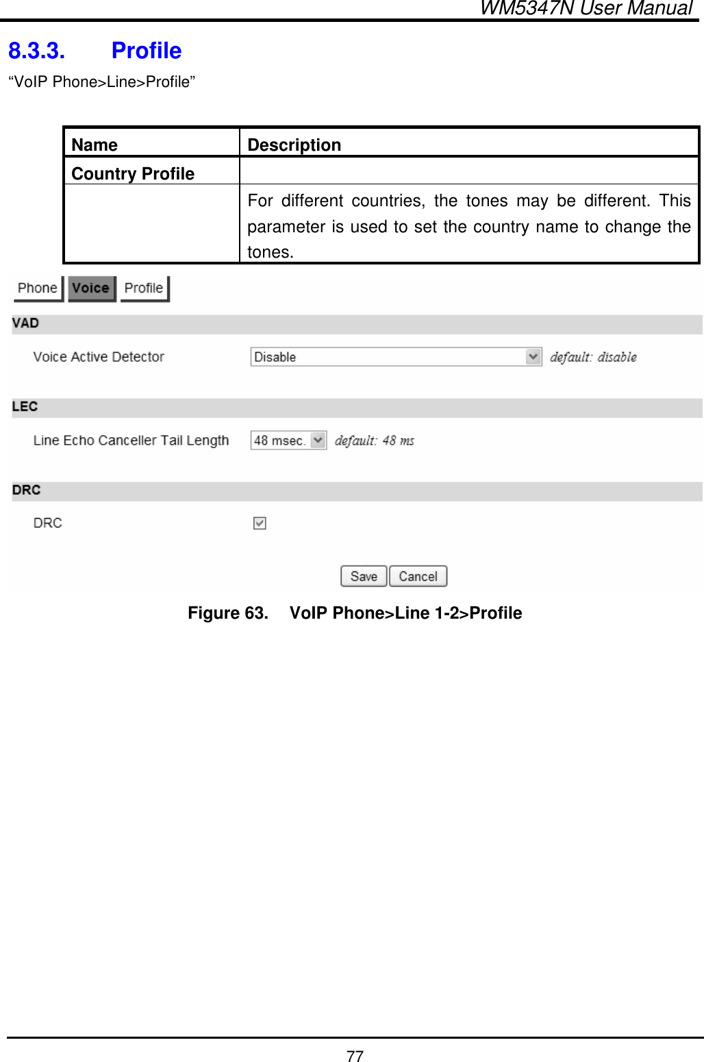
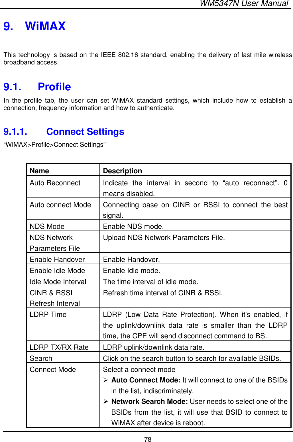
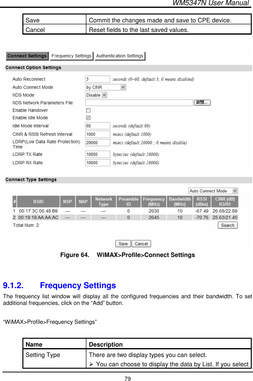
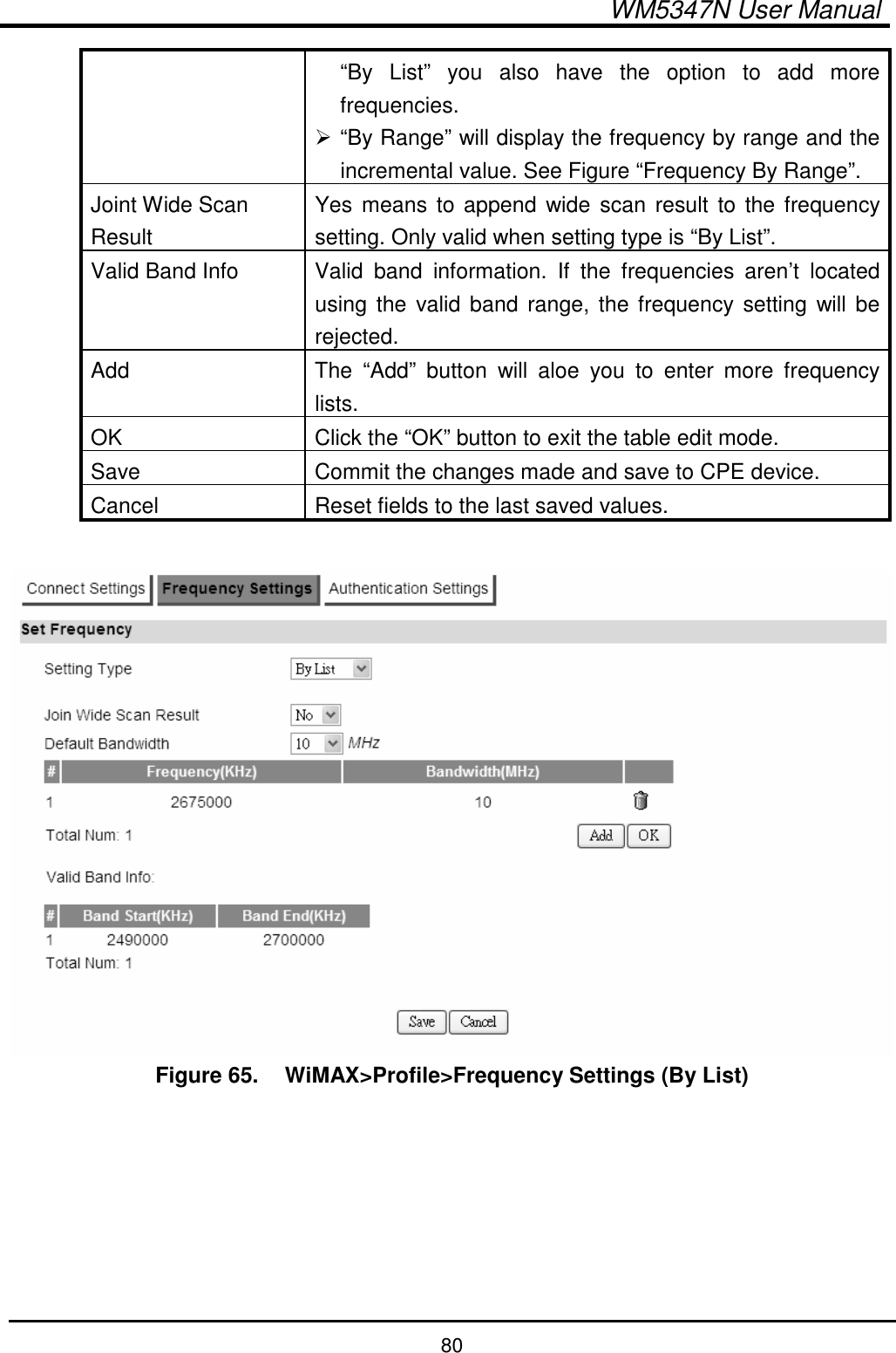
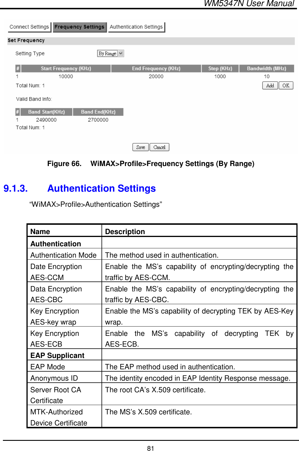
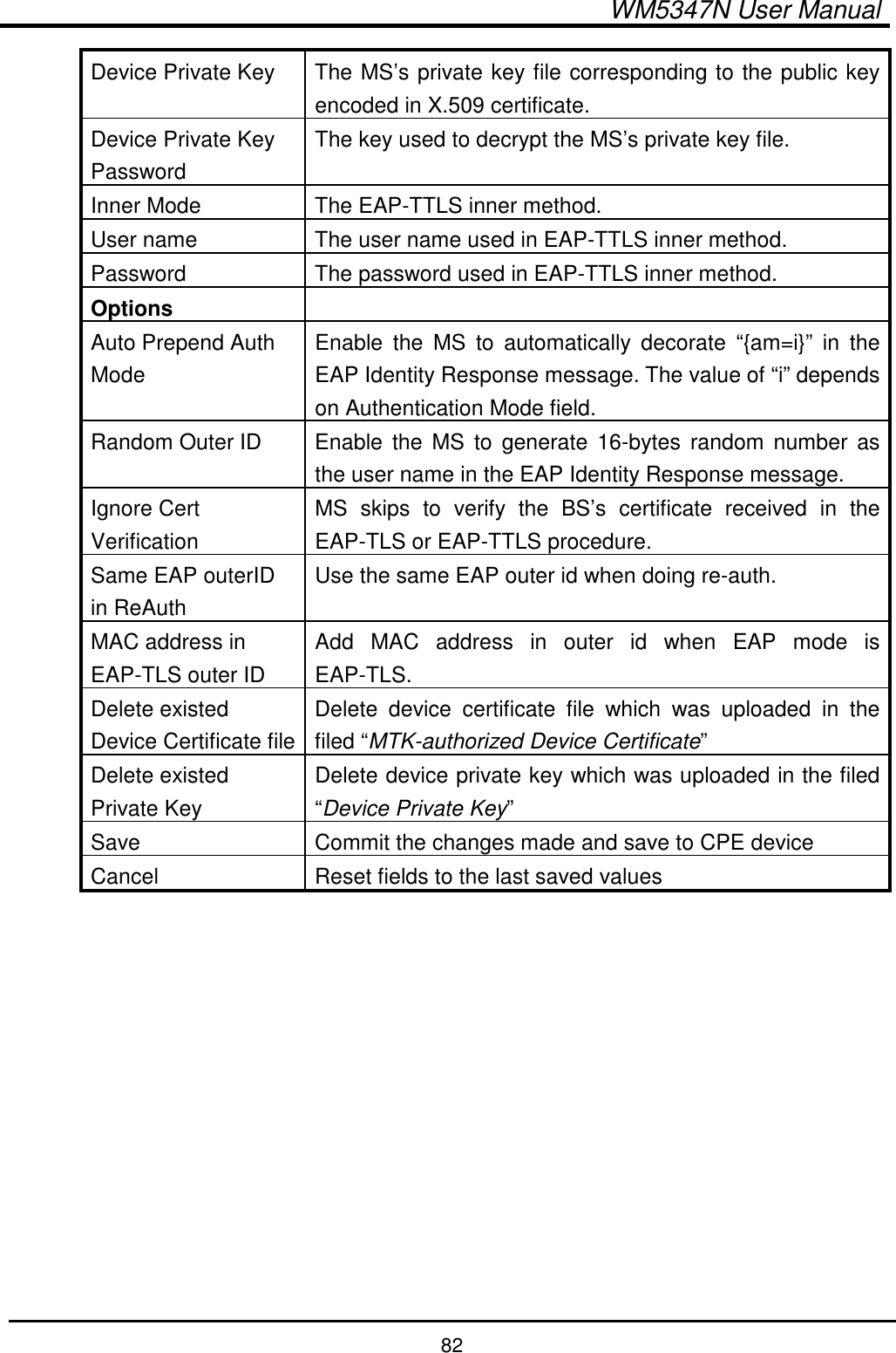
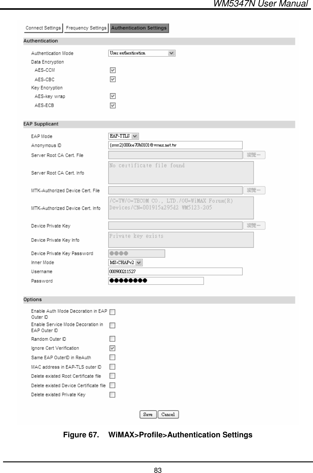
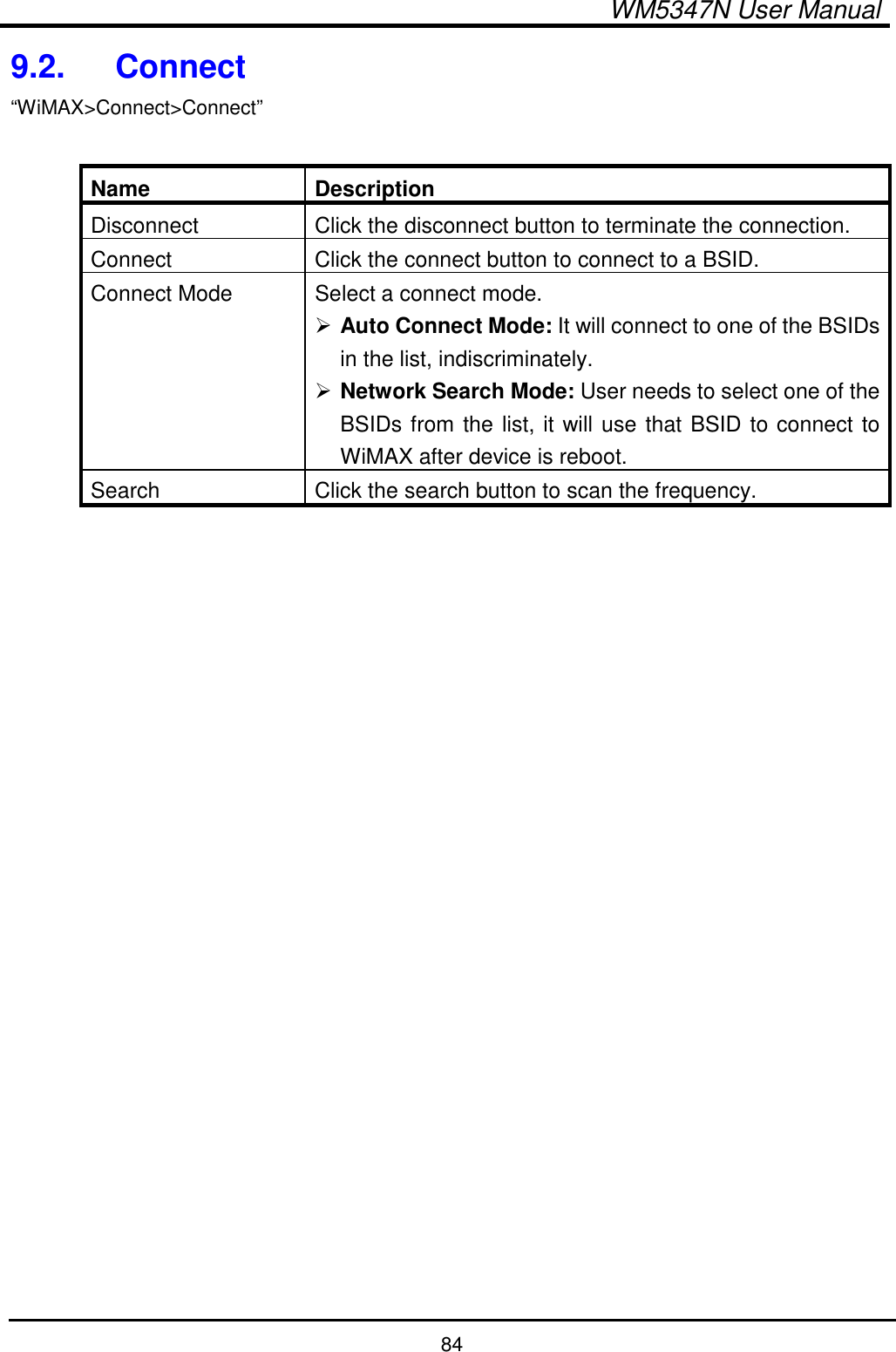
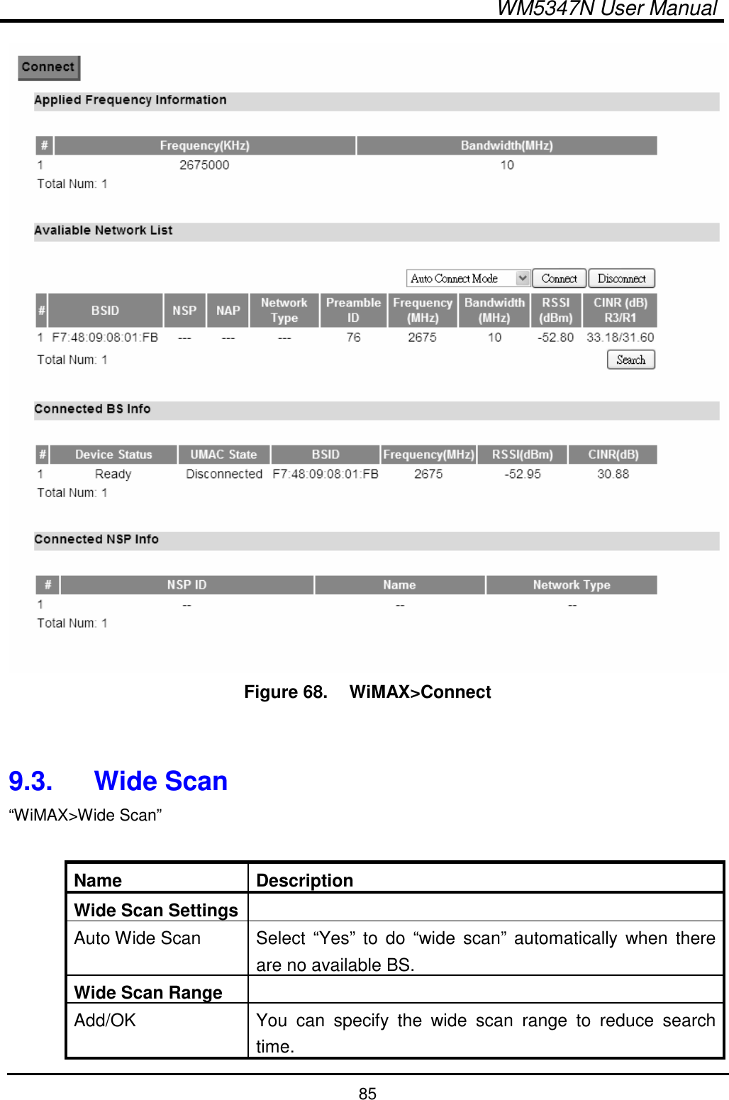
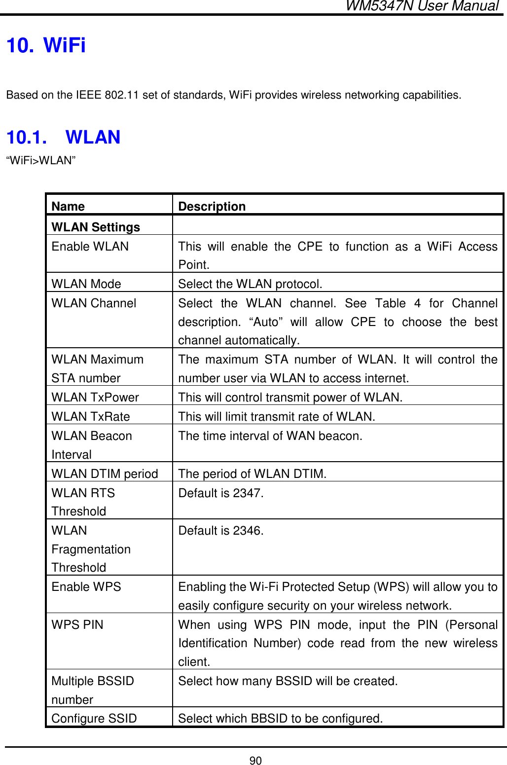
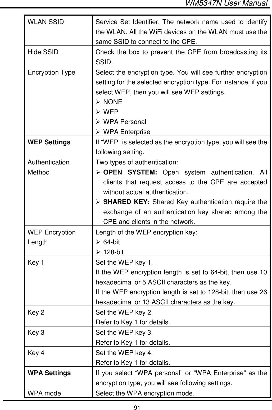
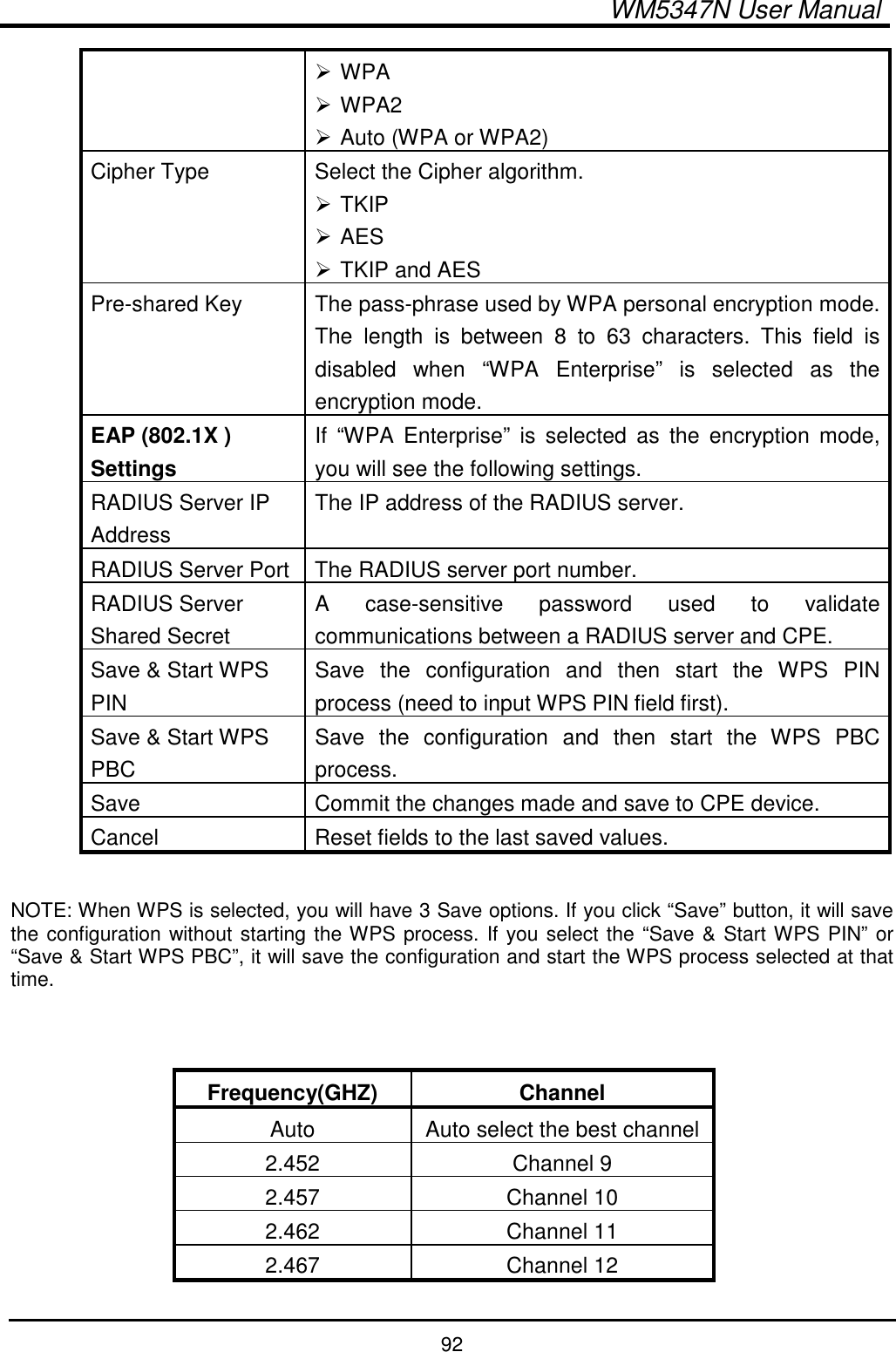
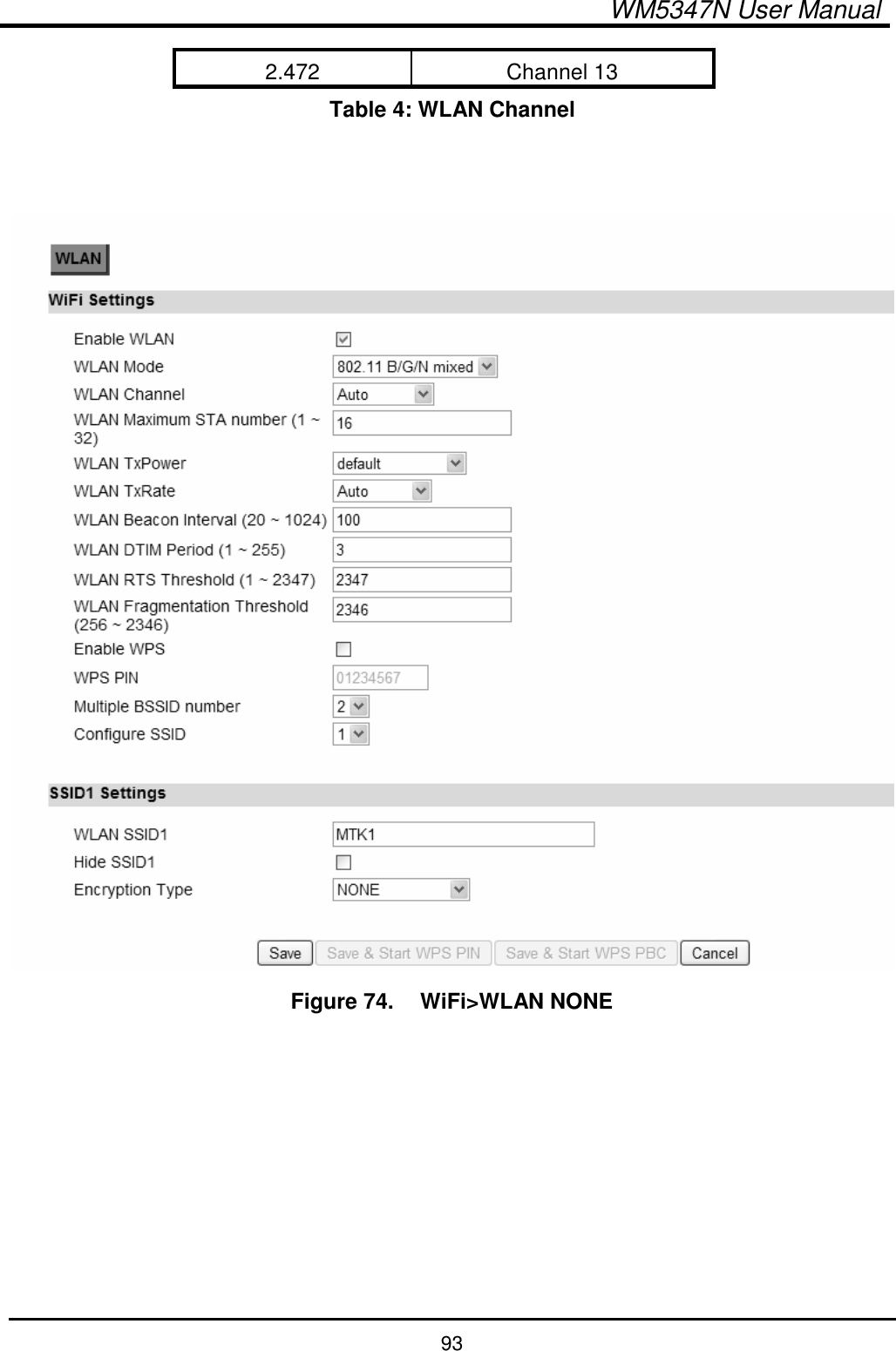
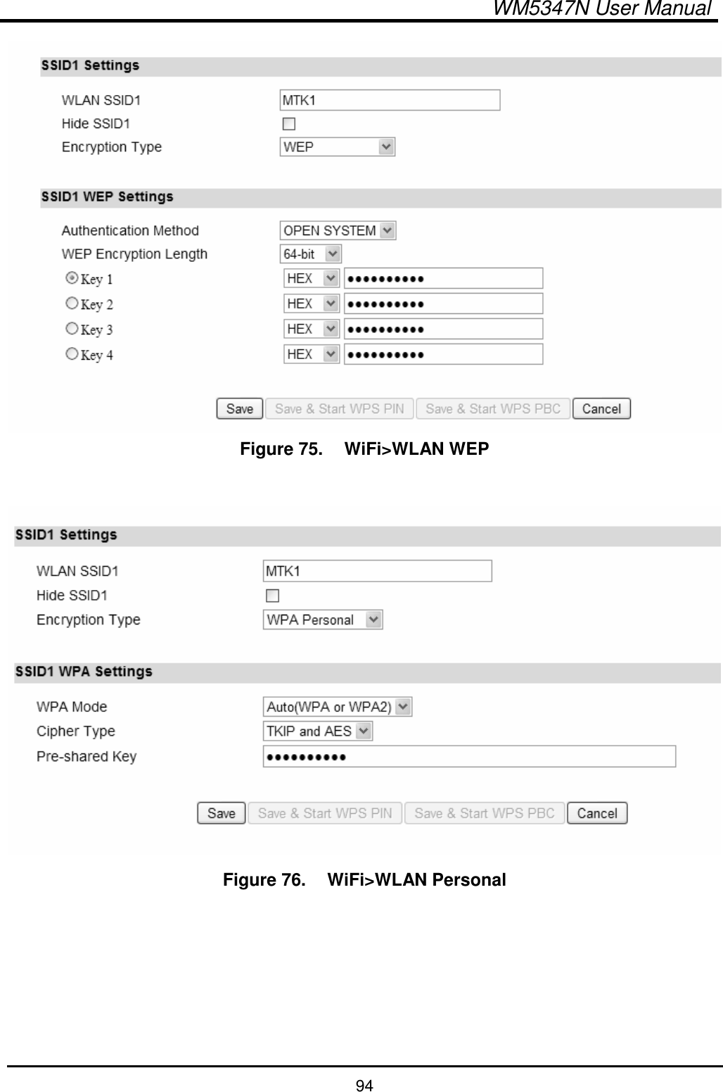
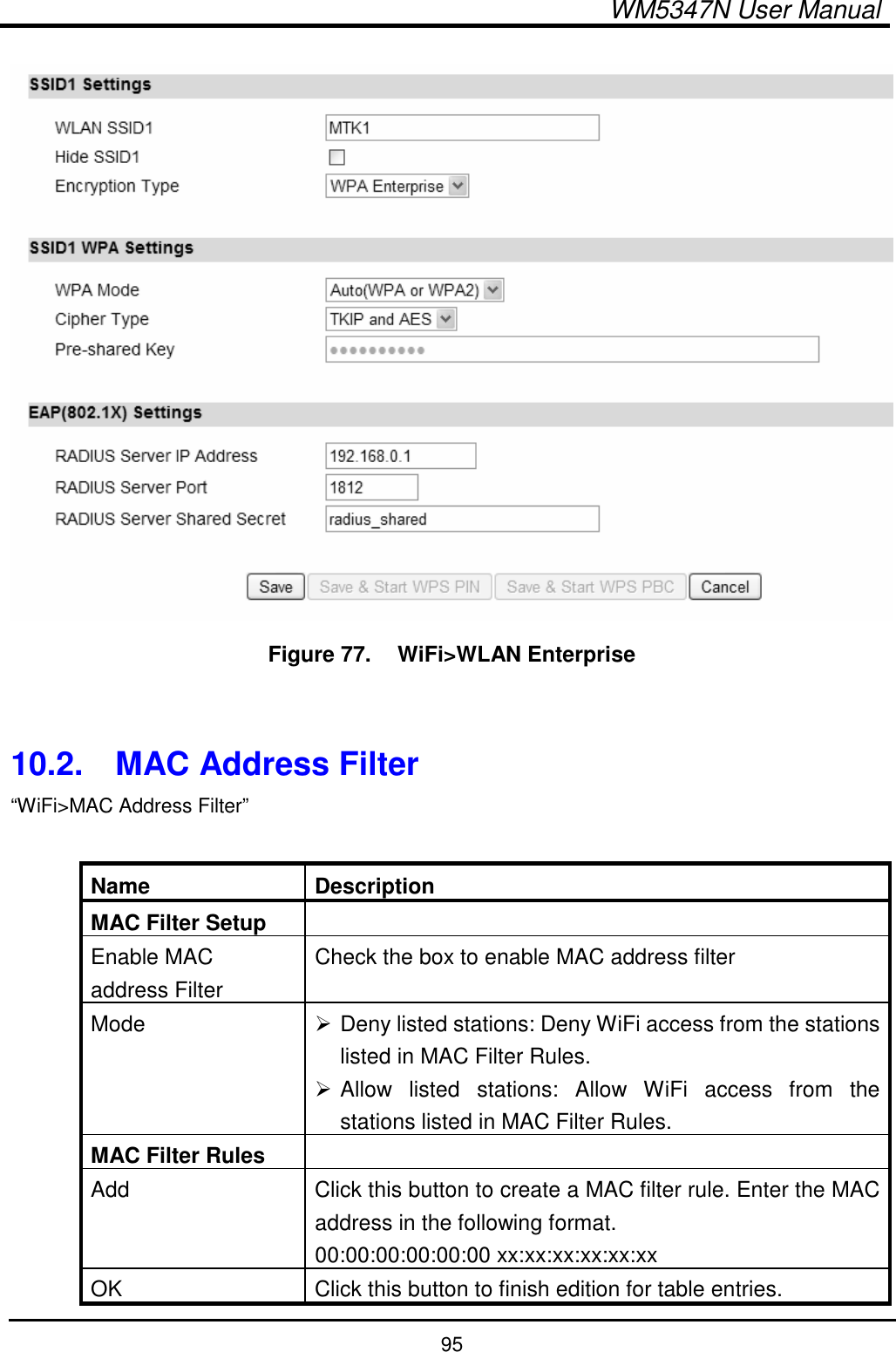
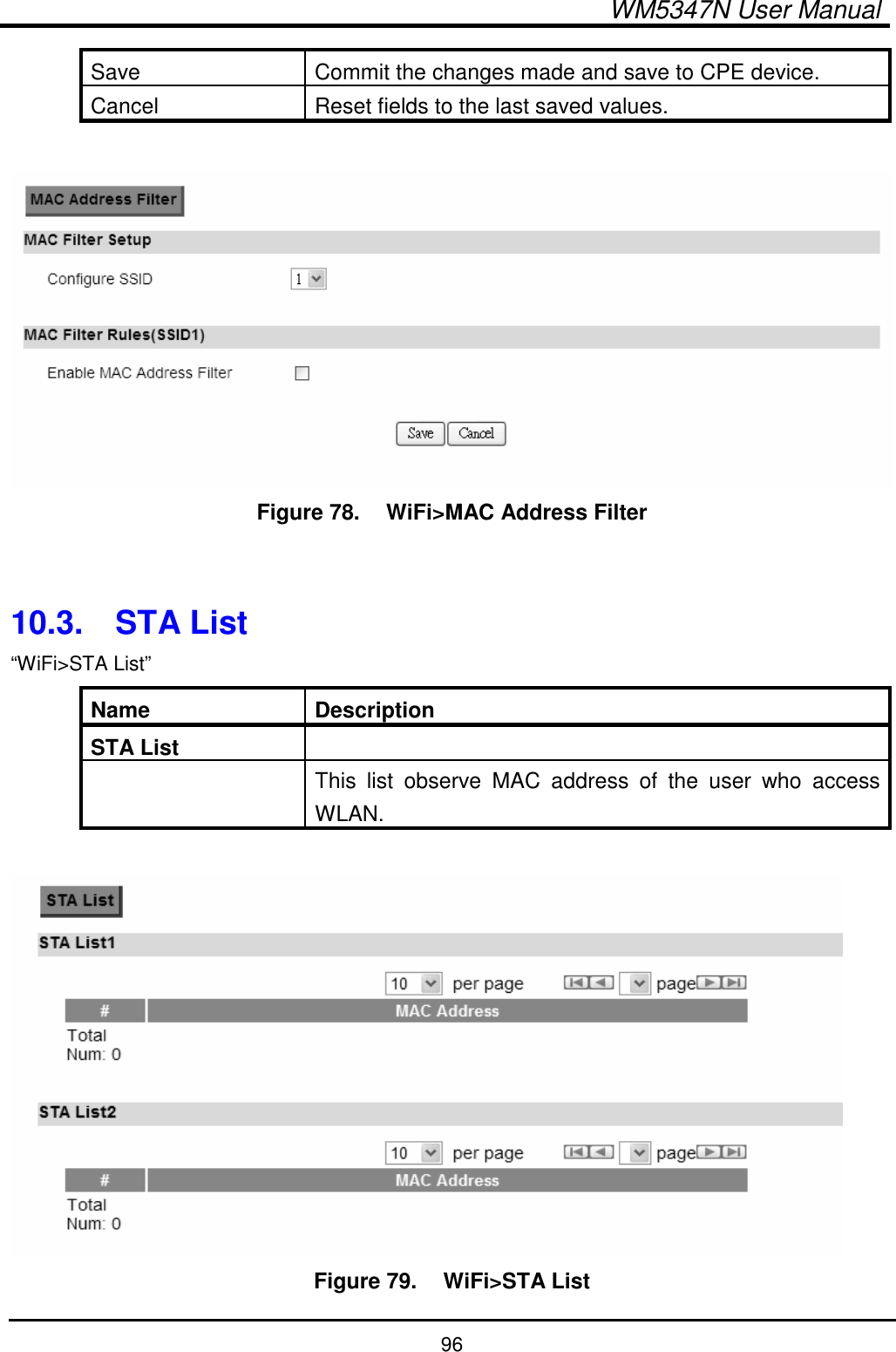
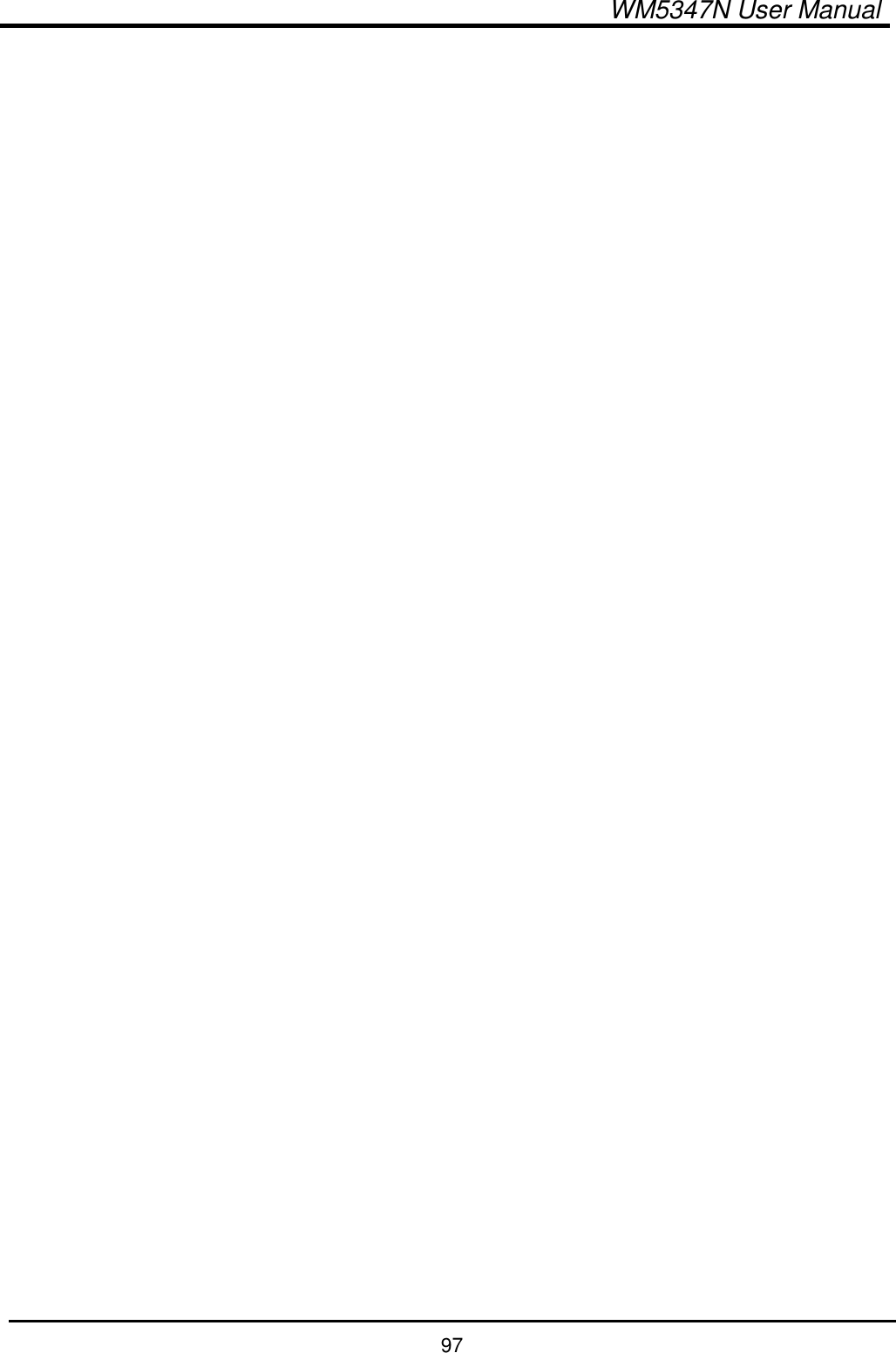
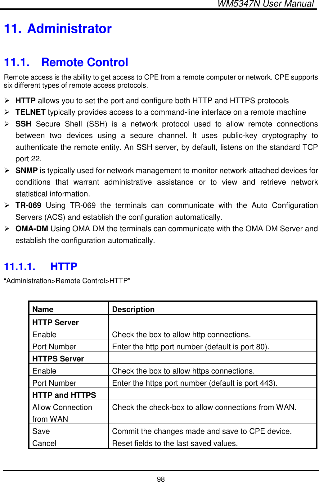
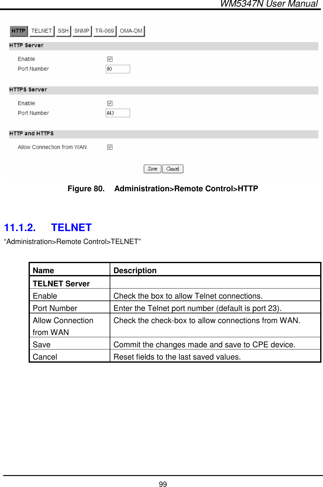
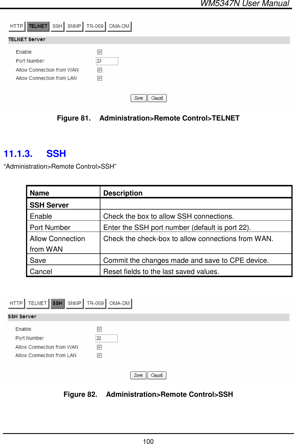
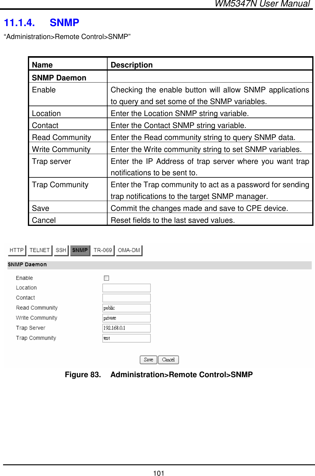
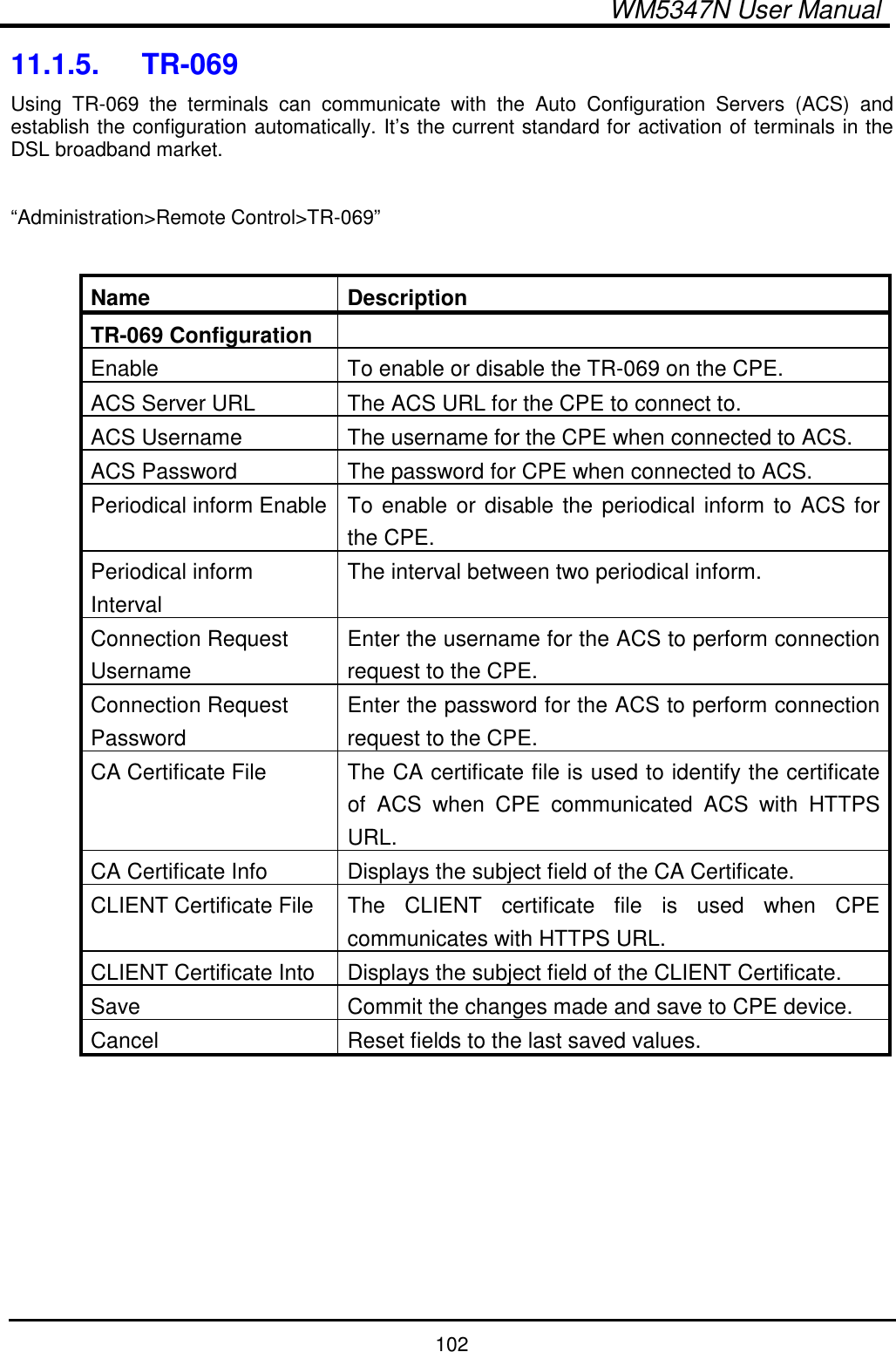
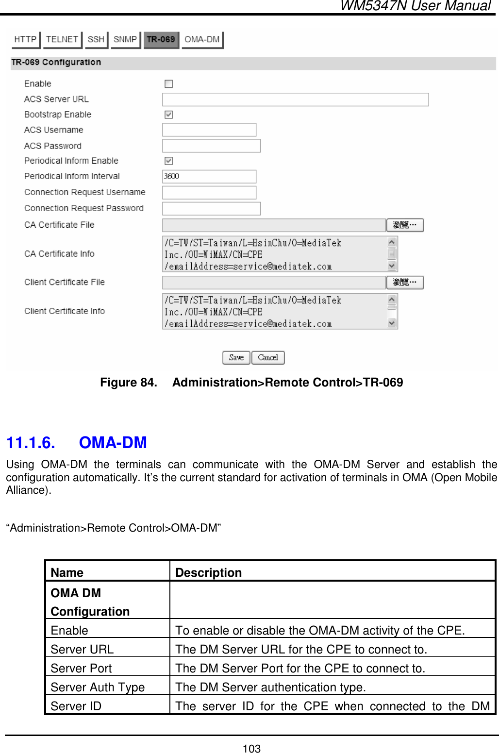
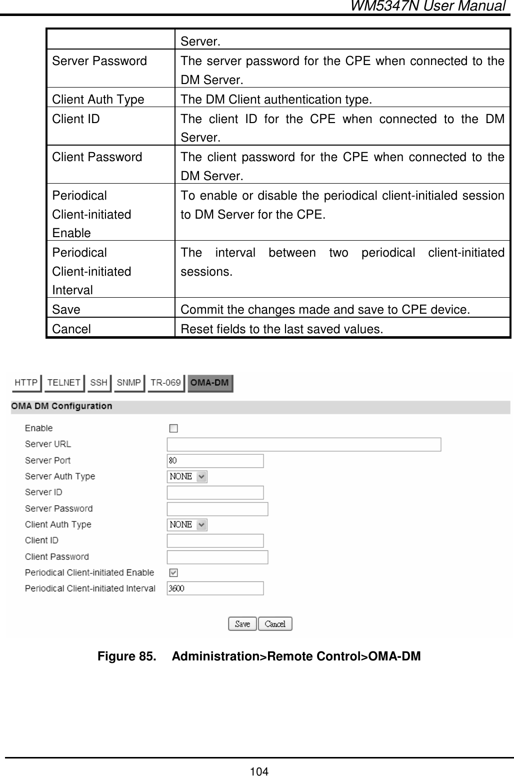
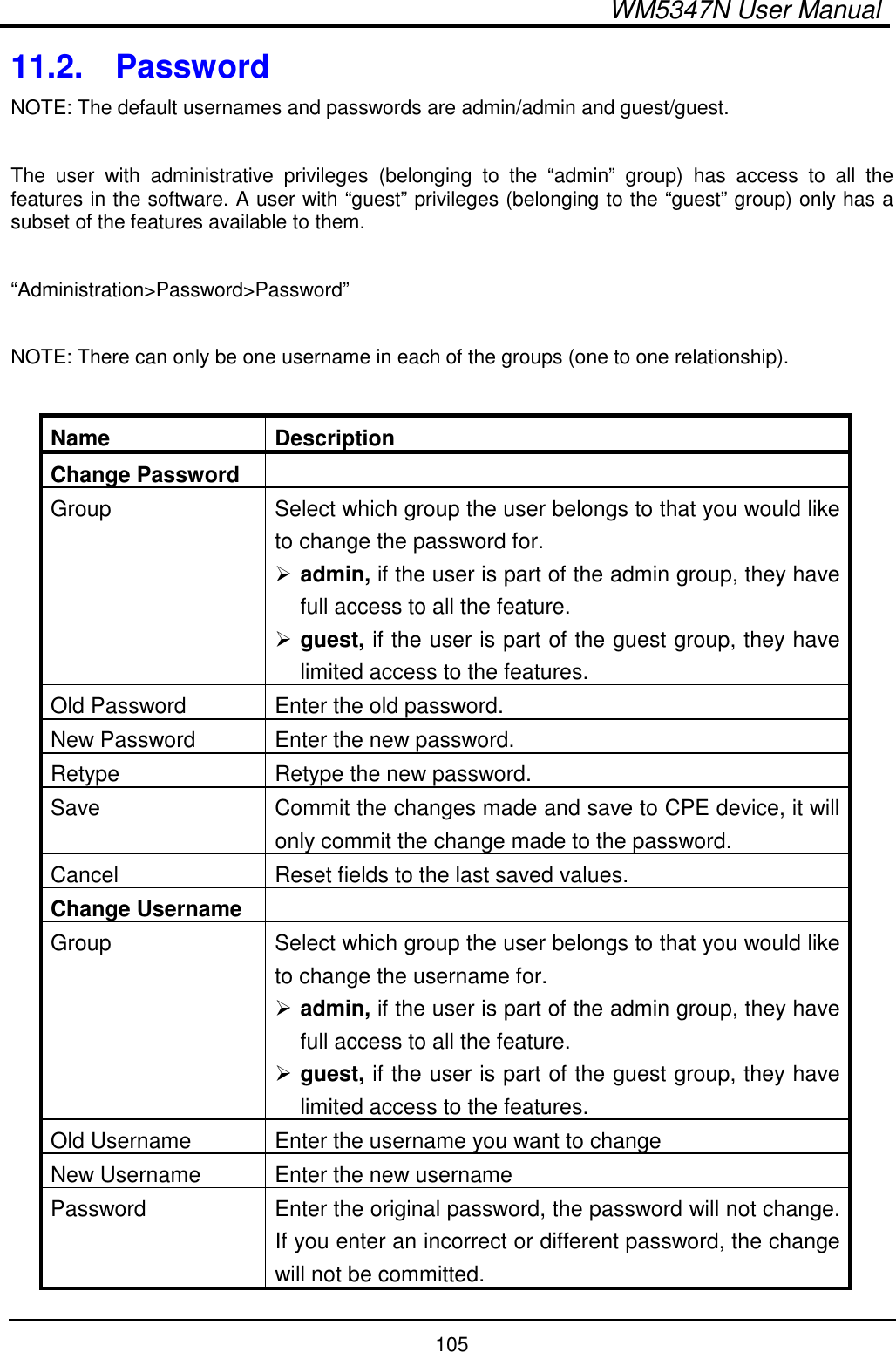
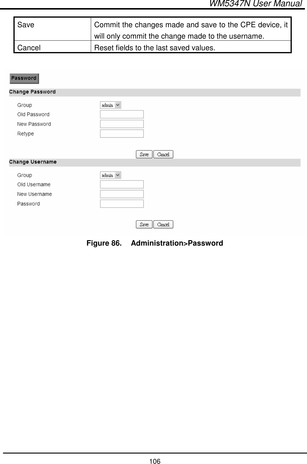
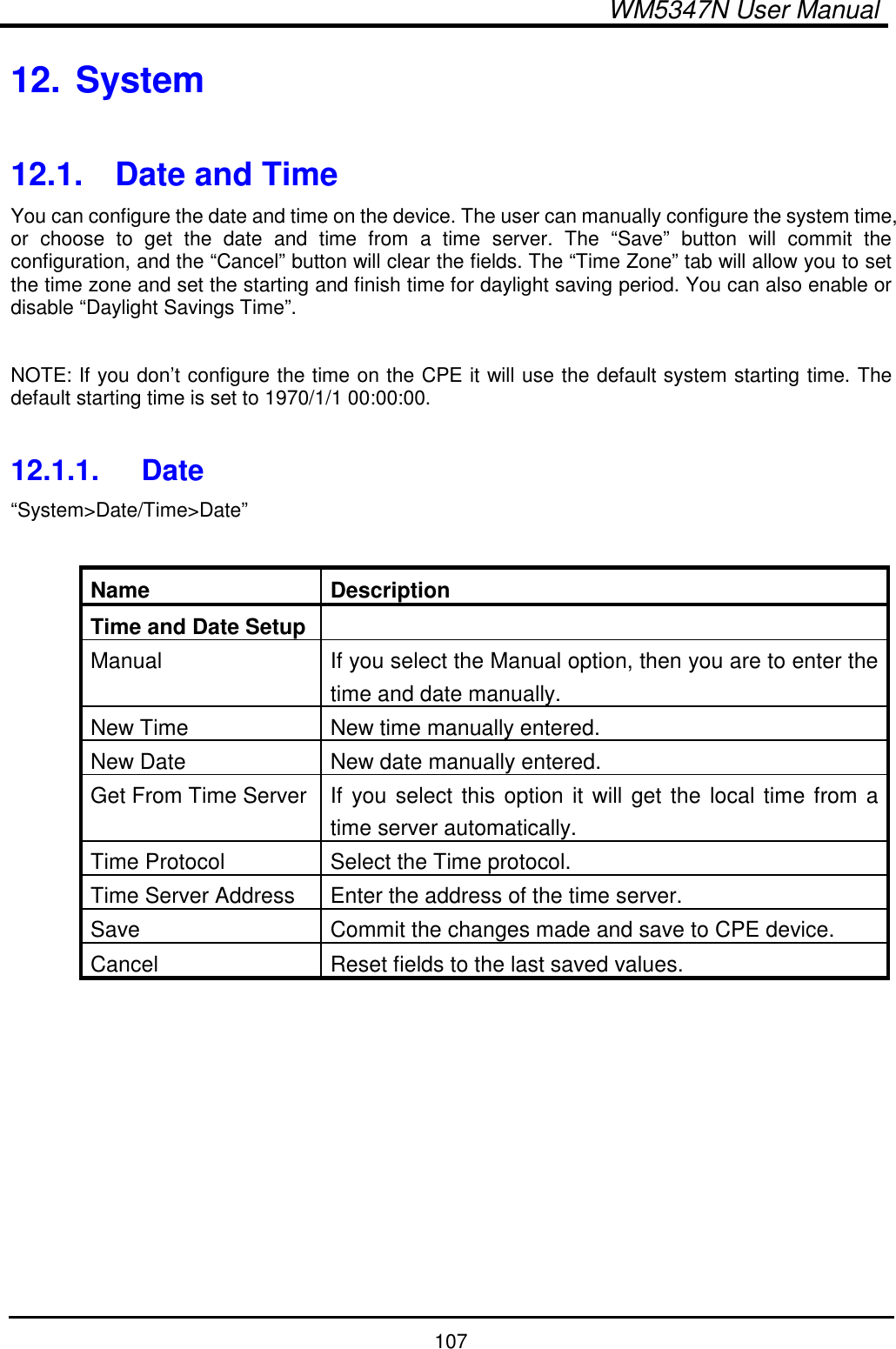
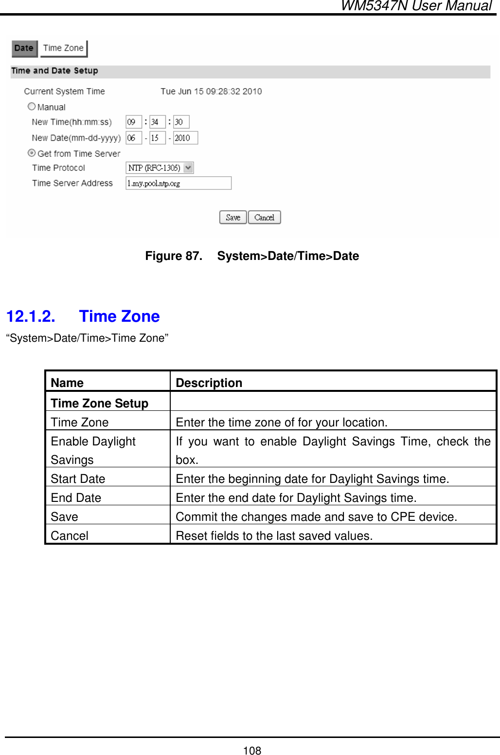
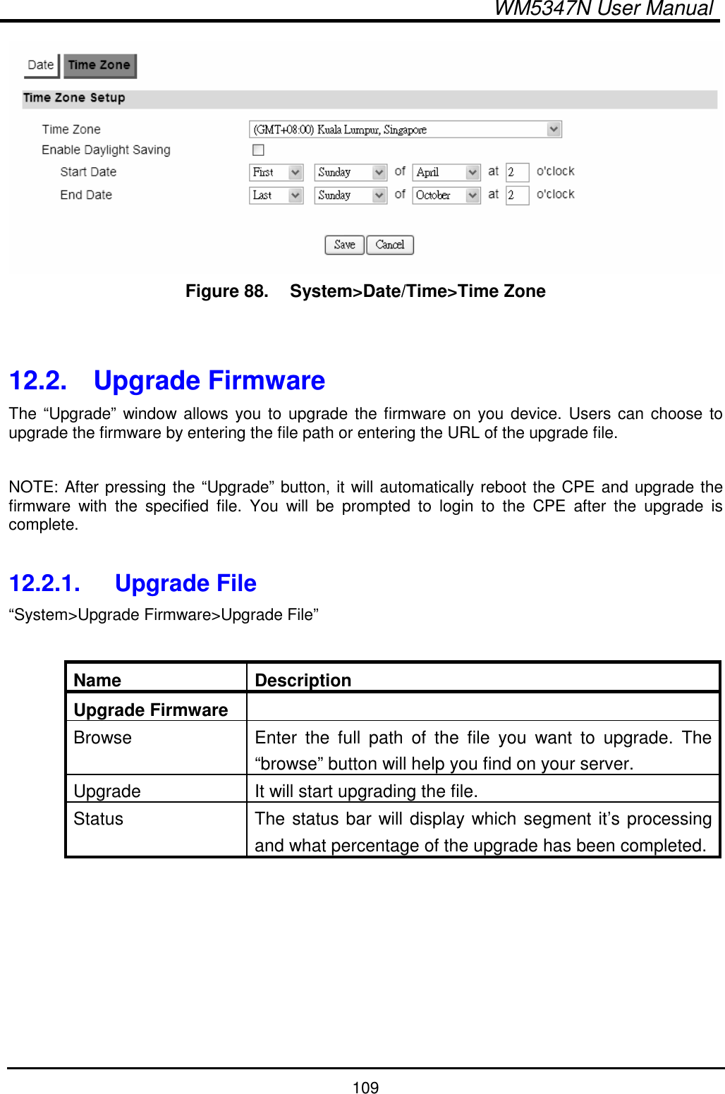
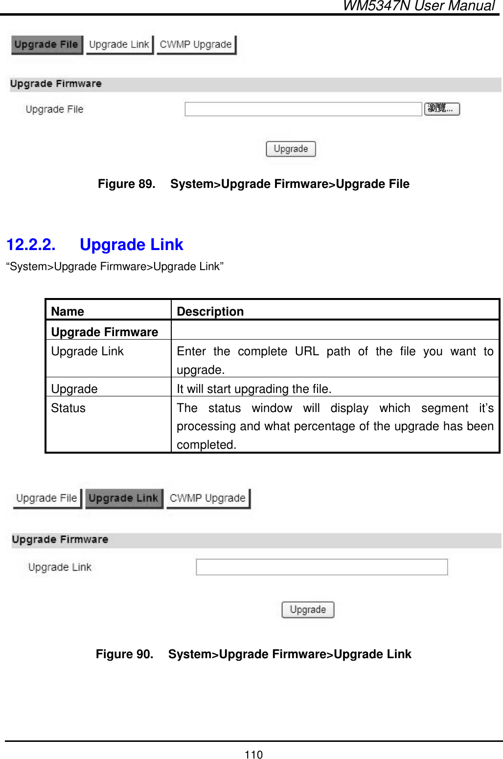
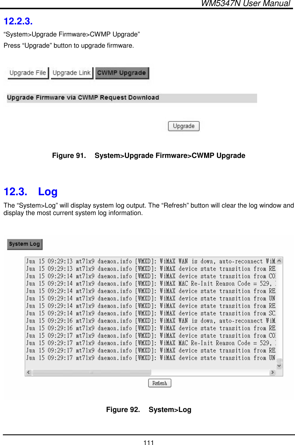
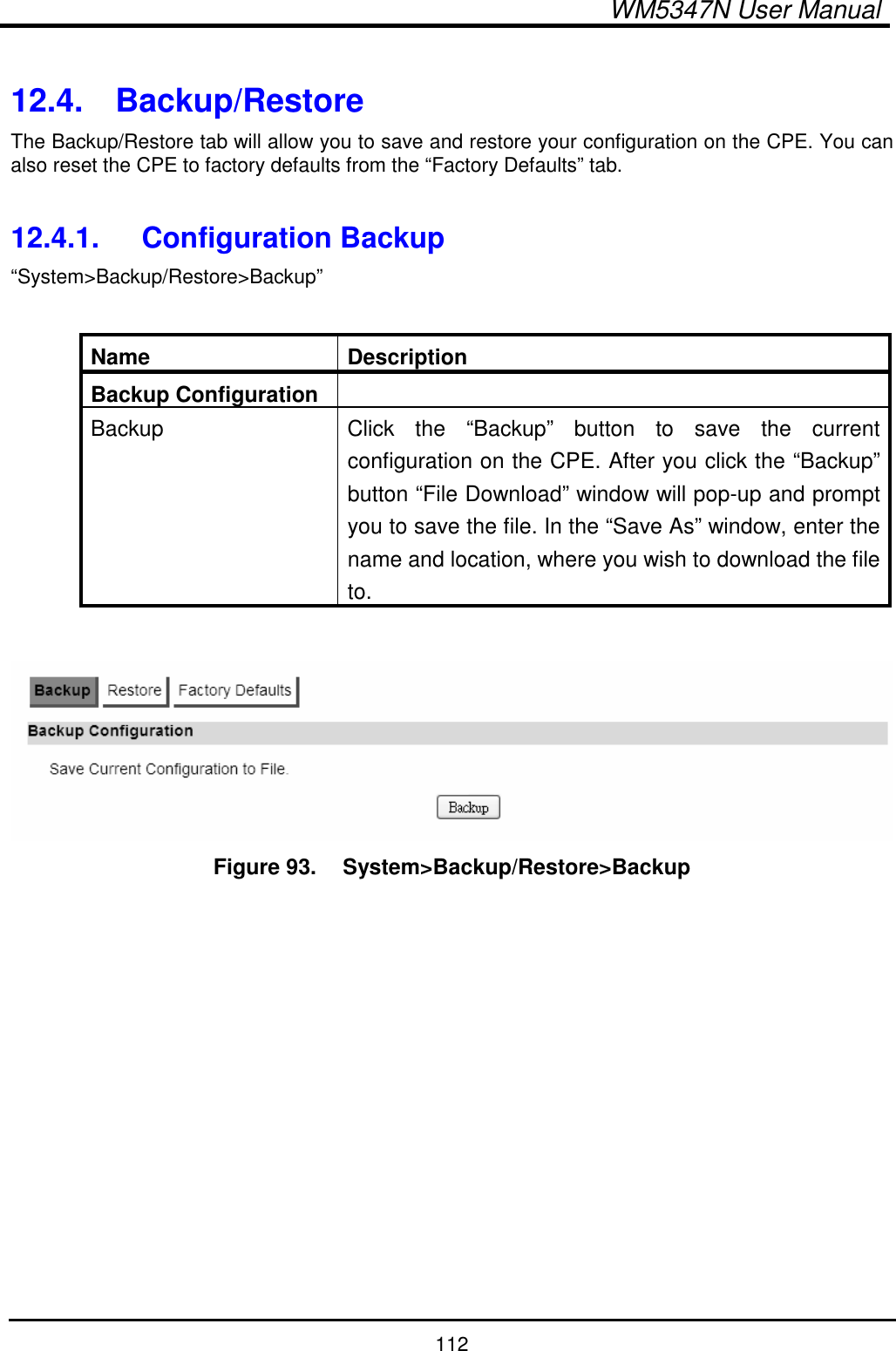
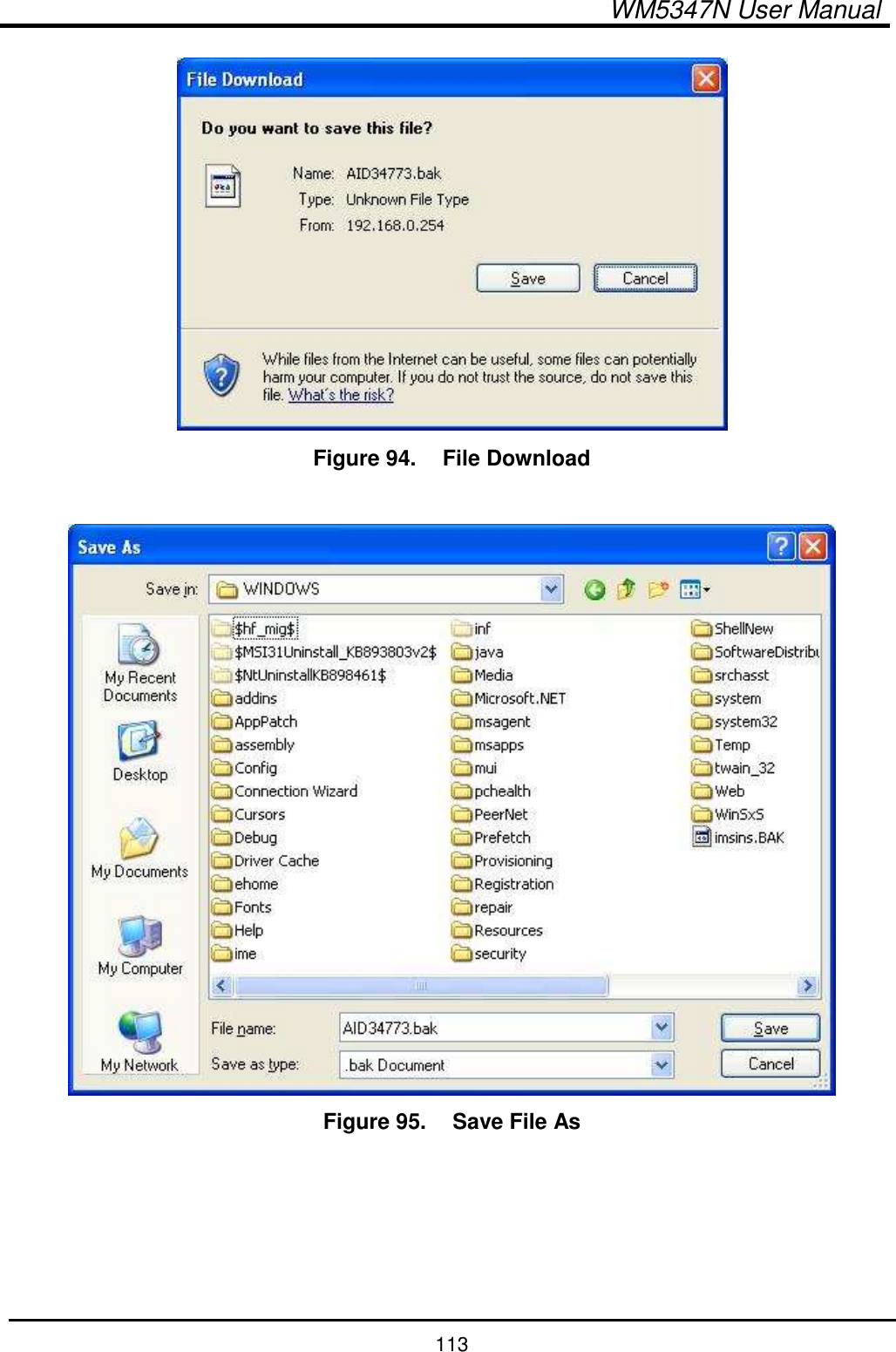
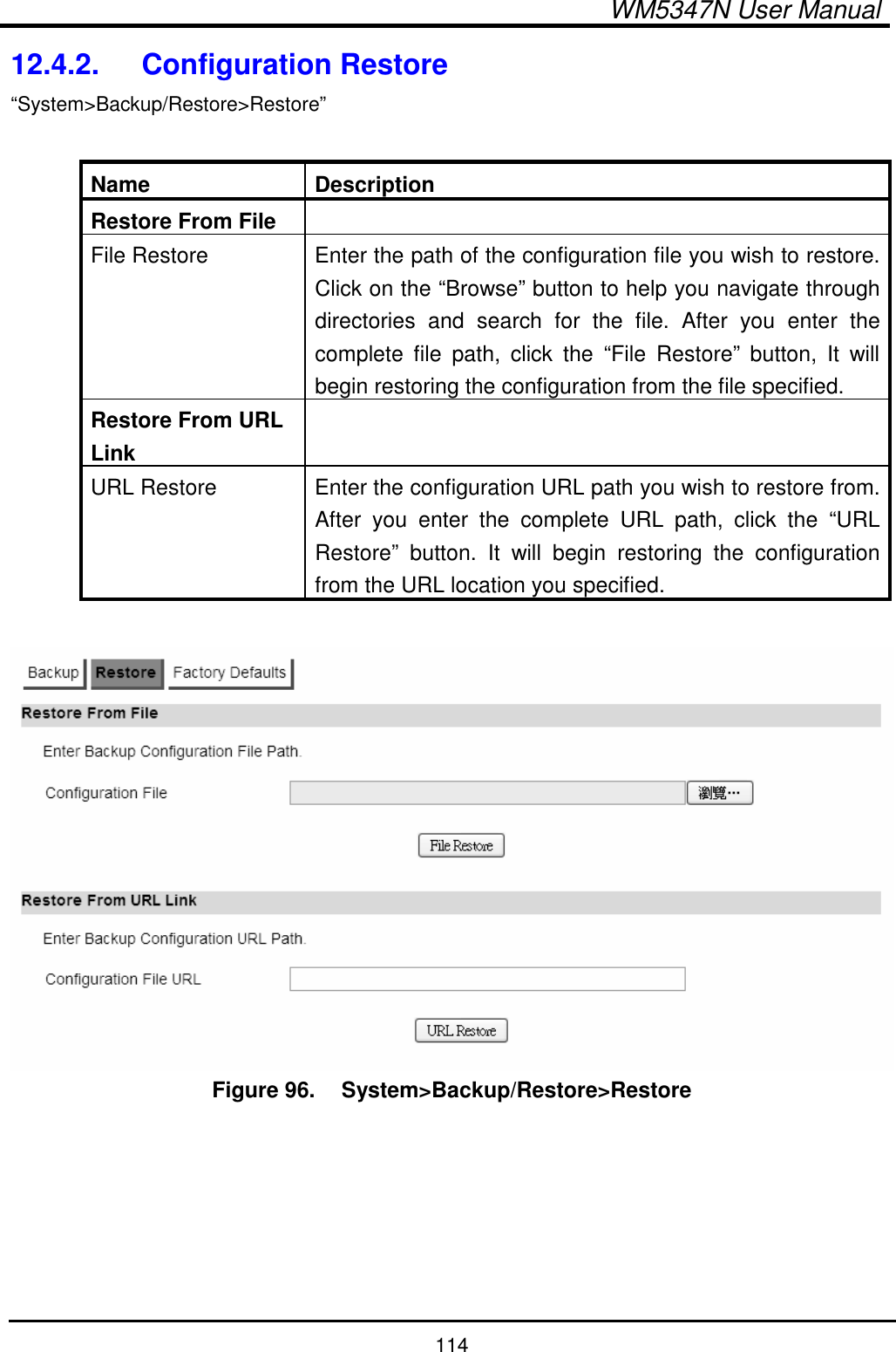
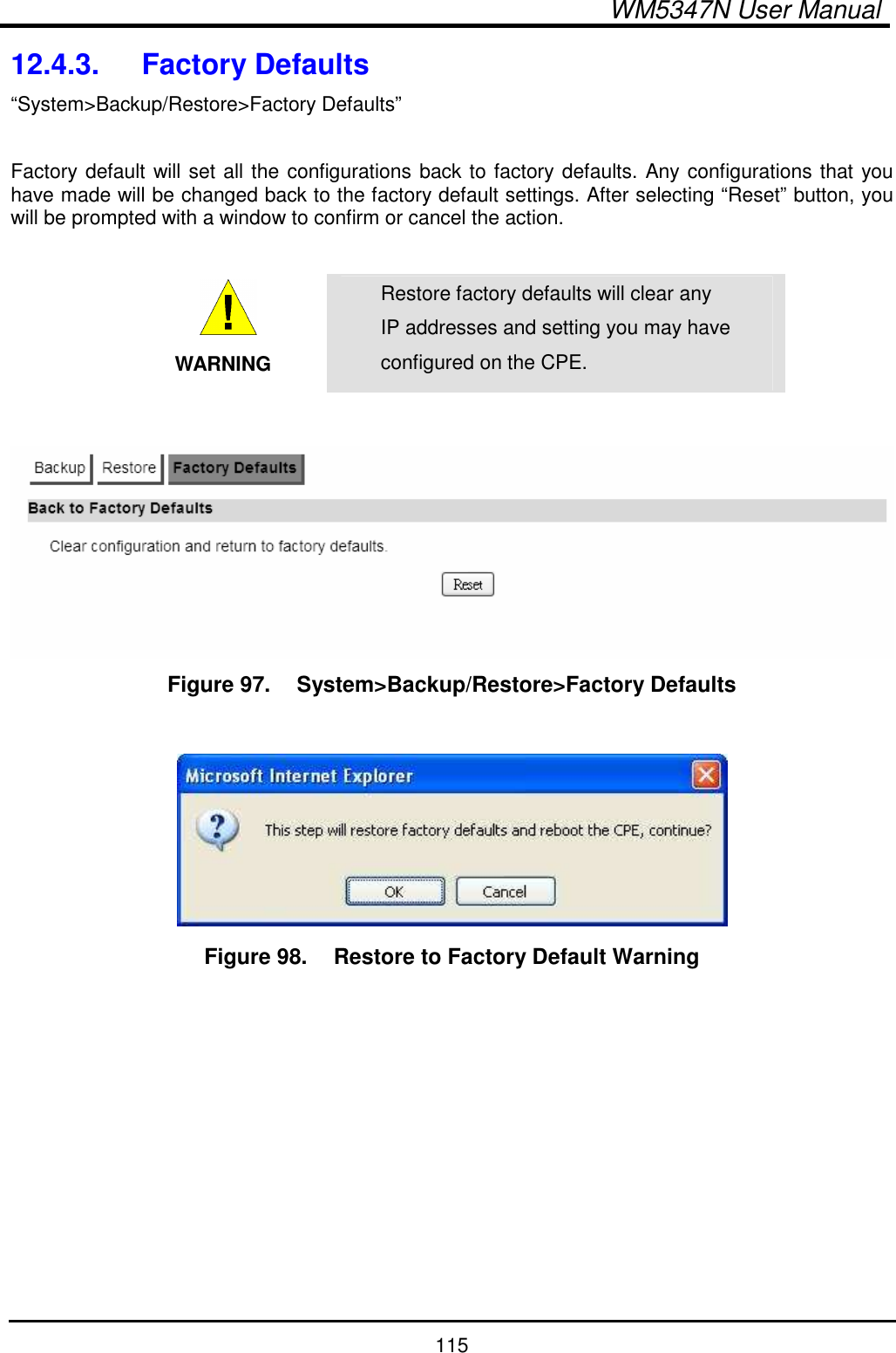
User Manual
user manual
Navigation menu
Upload a User Manual
Namespaces
Wiki Guide
HTML
PDF
Info
Views
User Manual
Discussion / Help
Navigation