Tecom Co WM5347N WiMAX Indoor CPE User Manual WM5347N v1 3b nc
Tecom Co Ltd WiMAX Indoor CPE WM5347N v1 3b nc
Tecom Co >
Contents
- 1. user manual
- 2. revised manual
- 3. User Manual
user manual

Users Manual
Version: 1.3b
Release Date: 2010-10-06
Copyright © 2010
TECOM communications
WIMAX CPE
WM5347N

WM5347N User Manual
i
Revision and Amendment Records
Revision Date Descriptions Author
1.0 2010-03-12 Initial Draft Hsling Lin
1.1 2010-03-19 Initial Release Hsling Lin
1.2 2010-06-15 Initial Release Dennis Tien
1.3b 2010-10-06 Release Dennis Tien,
Kevin Tsou

WM5347N User Manual
ii
Table of Contents
1. OVERVIEW....................................................................................................................1
2. INSTALLATION.............................................................................................................2
2.1.
I
N
T
HE
B
OX
......................................................................................................................... 2
2.2.
I
NDICATORS
........................................................................................................................ 3
2.3.
C
ONNECTORS
..................................................................................................................... 4
2.4.
N
ETWORK
C
ONNECTION
...................................................................................................... 6
3. INTRODUCTION ...........................................................................................................8
3.1.
C
ONNECT
........................................................................................................................... 8
3.2.
L
OGOUT
.............................................................................................................................. 9
3.3.
H
OME
................................................................................................................................. 9
3.4.
A
BOUT
...............................................................................................................................10
4. WIZARD.......................................................................................................................11
5. NETWORK ..................................................................................................................16
5.1.
LAN ..................................................................................................................................16
5.1.1.
IP...............................................................................................................................16
5.1.2.
DHCP........................................................................................................................17
5.2.
WAN.................................................................................................................................19
5.2.1.
WAN..........................................................................................................................19
5.2.2.
PPPoE.......................................................................................................................21
5.2.3.
GRE ..........................................................................................................................23
5.2.4.
EtherIP ......................................................................................................................24
5.3.
VLAN................................................................................................................................25
5.4.
DDNS ...............................................................................................................................27
6. ADVANCED SETTING................................................................................................29
6.1.
NAT..................................................................................................................................29
6.1.1.
Port Forward..............................................................................................................29
6.1.2.
Port Trigger ...............................................................................................................31
6.1.3.
DMZ ..........................................................................................................................33
6.1.4.
ALG...........................................................................................................................34
6.2.
F
IREWALL
..........................................................................................................................35
6.2.1.
IP Filter......................................................................................................................35
6.2.2.
MAC Filter .................................................................................................................36
6.2.3.
DDOS........................................................................................................................37
6.3.
R
OUTE
...............................................................................................................................38
6.3.1.
Static Route...............................................................................................................38
6.3.2.
RIP ............................................................................................................................39
6.4.
UP
N
P................................................................................................................................42
6.4.1.
UPnP Setting.............................................................................................................42

WM5347N User Manual
iii
6.5.
IGMP
P
ROXY
.....................................................................................................................42
6.5.1.
IGMP Proxy Setting...................................................................................................42
6.6.
C
ONTENT
F
ILTER
................................................................................................................43
7. VPN SETTING............................................................................................................. 45
7.1.
PPTP................................................................................................................................45
7.1.1.
PPTP Server .............................................................................................................45
7.1.2.
PPTP Client...............................................................................................................47
7.2.
L2TP.................................................................................................................................49
7.2.1.
L2TP Server ..............................................................................................................49
7.2.2.
L2TP Client................................................................................................................51
7.3.
IP
SEC
................................................................................................................................53
7.3.1.
Connection ................................................................................................................53
8. VOIP PHONE...............................................................................................................59
8.1.
G
ENERAL
...........................................................................................................................59
8.1.1.
System ......................................................................................................................59
8.1.2.
Media ........................................................................................................................59
8.1.3.
QoS...........................................................................................................................61
8.1.4.
Provision....................................................................................................................62
8.2.
A
CCOUNT
..........................................................................................................................63
8.2.1.
Status........................................................................................................................63
8.2.2.
Server........................................................................................................................64
8.2.3.
User...........................................................................................................................66
8.2.4.
Feature......................................................................................................................69
8.2.5.
Dialing .......................................................................................................................71
8.2.6.
Speed Dial.................................................................................................................72
8.2.7.
FAX ...........................................................................................................................73
8.2.8.
RTP...........................................................................................................................73
8.3.
L
INE
..................................................................................................................................74
8.3.1.
Phone........................................................................................................................74
8.3.2.
Voice .........................................................................................................................75
8.3.3.
Profile........................................................................................................................77
9. WIMAX......................................................................................................................... 78
9.1.
P
ROFILE
............................................................................................................................78
9.1.1.
Connect Settings .......................................................................................................78
9.1.2.
Frequency Settings....................................................................................................79
9.1.3.
Authentication Settings..............................................................................................81
9.2.
C
ONNECT
..........................................................................................................................84
9.3.
W
IDE
S
CAN
........................................................................................................................85
9.4.
L
INK
S
TATUS
......................................................................................................................86
9.5.
L
INK
S
TATISTICS
................................................................................................................87
9.6.
C
ONNECTION
I
NFO
.............................................................................................................88
9.7.
S
ERVICE
F
LOW
..................................................................................................................89
10. WIFI..........................................................................................................................90

WM5347N User Manual
iv
10.1.
WLAN...............................................................................................................................90
10.2.
MAC
A
DDRESS
F
ILTER
.......................................................................................................95
10.3.
STA
L
IST
...........................................................................................................................96
11. ADMINISTRATOR.................................................................................................... 98
11.1.
R
EMOTE
C
ONTROL
.............................................................................................................98
11.1.1.
HTTP.........................................................................................................................98
11.1.2.
TELNET.....................................................................................................................99
11.1.3.
SSH.........................................................................................................................100
11.1.4.
SNMP......................................................................................................................101
11.1.5.
TR-069 ....................................................................................................................102
11.1.6.
OMA-DM .................................................................................................................103
11.2.
P
ASSWORD
......................................................................................................................105
12. SYSTEM................................................................................................................. 107
12.1.
D
ATE AND
T
IME
................................................................................................................107
12.1.1.
Date.........................................................................................................................107
12.1.2.
Time Zone ...............................................................................................................108
12.2.
U
PGRADE
F
IRMWARE
.......................................................................................................109
12.2.1.
Upgrade File............................................................................................................109
12.2.2.
Upgrade Link...........................................................................................................110
12.2.3. 111
12.3.
L
OG
.................................................................................................................................111
12.4.
B
ACKUP
/R
ESTORE
...........................................................................................................112
12.4.1.
Configuration Backup ..............................................................................................112
12.4.2.
Configuration Restore..............................................................................................114
12.4.3.
Factory Defaults ......................................................................................................115

WM5347N User Manual
v
List of Figures
F
IGURE
1. D
EVICE
I
NSTALLATION
.......................................................................................... 2
F
IGURE
2. D
EVICE
F
RONT
P
ANEL
......................................................................................... 3
F
IGURE
3. D
EVICE
P
EAR
P
ANEL
........................................................................................... 4
F
IGURE
4. O
VERVIEW OF
H
ARDWARE
C
ONNECTIONS
............................................................. 6
F
IGURE
5. L
OGIN
................................................................................................................. 8
F
IGURE
6. L
OGOUT
............................................................................................................. 9
F
IGURE
7. H
OME
................................................................................................................. 9
F
IGURE
8. A
BOUT
CPE
C
ONFIGURATION
M
ANAGER
............................................................. 10
F
IGURE
9. W
IZARD
LAN
S
ETTINGS
..................................................................................... 11
F
IGURE
10. W
IZARD
W
I
MAX
F
REQUENCY
(B
Y
L
IST
).............................................................. 12
F
IGURE
11. W
IZARD
W
I
MAX
F
REQUENCY
(B
Y
R
ANGE
) ......................................................... 12
F
IGURE
12. W
IZARD
W
I
MAX
A
UTHENTICATION
S
ETTINGS
...................................................... 13
F
IGURE
13. W
IZARD
V
O
IP
S
ETTINGS
.................................................................................... 13
F
IGURE
14. W
IZARD
WLAN
S
ETTINGS
................................................................................. 14
F
IGURE
15. W
IZARD
S
AVE
................................................................................................... 15
F
IGURE
16. N
ETWORK
T
OPOLOGY
........................................................................................ 16
F
IGURE
17. N
ETWORK
>LAN>IP .......................................................................................... 17
F
IGURE
18. N
ETWORK
>LAN>DHCP.................................................................................... 19
F
IGURE
19. N
ETWORK
>WAN>WAN.................................................................................... 21
F
IGURE
20. N
ETWORK
>WAN>PPP
O
E................................................................................. 23
F
IGURE
21. N
ETWORK
>WAN>GRE..................................................................................... 24
F
IGURE
22. N
ETWORK
>WAN>E
THER
IP............................................................................... 24
F
IGURE
23. N
ETWORK
>VLAN ............................................................................................. 26
F
IGURE
24. N
ETWORK
>DDNS............................................................................................. 28
F
IGURE
25. A
DVANCED
>NAT>P
ORT
F
ORWARD
.................................................................... 30
F
IGURE
26. A
DVANCED
>NAT>P
ORT
F
ORWARD
>W
IZARD
...................................................... 31
F
IGURE
27. A
DVANCED
>NAT>P
ORT
T
RIGGER
...................................................................... 32
F
IGURE
28. A
DVANCED
>NAT>P
ORT
T
RIGGER
>W
IZARD
........................................................ 33
F
IGURE
29. A
DVANCED
>NAT>DMZ..................................................................................... 34
F
IGURE
30. A
DVANCED
>NAT>ALG ..................................................................................... 35
F
IGURE
31. A
DVANCED
>F
IREWALL
>IP
F
ILTER
...................................................................... 36
F
IGURE
32. A
DVANCED
>F
IREWALL
>MAC
F
ILTER
.................................................................. 37

WM5347N User Manual
vi
F
IGURE
33. A
DVANCED
>F
IREWALL
>DDOS........................................................................... 38
F
IGURE
34. A
DVANCED
>R
OUTE
>S
TATIC
R
OUTE
................................................................... 39
F
IGURE
35. A
DVANCED
>R
OUTE
>S
TATIC
R
OUTE
>A
DD
........................................................... 39
F
IGURE
36. A
DVANCED
>R
OUTE
>RIP ................................................................................... 41
F
IGURE
37. A
DVANCED
>UP
N
P ............................................................................................ 42
F
IGURE
38. A
DVANCED
>IGMP
P
ROXY
................................................................................. 43
F
IGURE
39. A
DVANCED
>C
ONTENT
F
ILTER
............................................................................ 44
F
IGURE
40. VPN>PPTP
S
ERVER
........................................................................................ 47
F
IGURE
41. VPN>PPTP
C
LIENT
.......................................................................................... 48
F
IGURE
42. VPN>PPTP
C
LIENT
>A
DD
................................................................................. 48
F
IGURE
43. VPN>L2TP
S
ERVER
......................................................................................... 51
F
IGURE
44. VPN>L2TP
C
LIENT
.......................................................................................... 52
F
IGURE
45. VPN>L2TP
C
LIENT
>A
DD
.................................................................................. 53
F
IGURE
46. VPN>IP
SEC
>C
ONNECTION
O
VERVIEW
............................................................... 56
F
IGURE
47. VPN>IP
SEC
>C
ONNECTION
>A
DD
....................................................................... 57
F
IGURE
48. VPN>IP
SEC
>C
ONNECTION
>A
DD
(C
ONTINUED
)................................................... 58
F
IGURE
49. V
O
IP
P
HONE
>G
ENERAL
>S
YSTEM
...................................................................... 59
F
IGURE
50. V
O
IP
P
HONE
>G
ENERAL
>M
EDIA
......................................................................... 61
F
IGURE
51. V
O
IP
P
HONE
>G
ENERAL
>Q
O
S........................................................................... 62
F
IGURE
52. V
O
IP
P
HONE
>G
ENERAL
>P
ROVISION
.................................................................. 63
F
IGURE
53. V
O
IP
P
HONE
>A
CCOUNT
1-4>S
TATUS
................................................................ 64
F
IGURE
54. V
O
IP
P
HONE
>A
CCOUNT
1-2>S
ERVER
................................................................ 65
F
IGURE
55. V
O
IP
P
HONE
>A
CCOUNT
1-2>U
SER
.................................................................... 68
F
IGURE
56. V
O
IP
P
HONE
>A
CCOUNT
1-2>F
EATURE
.............................................................. 71
F
IGURE
57. V
O
IP
P
HONE
>A
CCOUNT
1-2>D
IALING
................................................................ 72
F
IGURE
58. V
O
IP
P
HONE
>A
CCOUNT
1-2>S
PEED
D
IAL
.......................................................... 73
F
IGURE
59. V
O
IP
P
HONE
>A
CCOUNT
1-2>FAX..................................................................... 73
F
IGURE
60. V
O
IP
P
HONE
>A
CCOUNT
1-2>RTP..................................................................... 74
F
IGURE
61. V
O
IP
P
HONE
>L
INE
1-2>P
HONE
......................................................................... 75
F
IGURE
62. V
O
IP
P
HONE
>L
INE
1-2>V
OICE
.......................................................................... 76
F
IGURE
63. V
O
IP
P
HONE
>L
INE
1-2>P
ROFILE
....................................................................... 77
F
IGURE
64. W
I
MAX>P
ROFILE
>C
ONNECT
S
ETTINGS
............................................................. 79
F
IGURE
65. W
I
MAX>P
ROFILE
>F
REQUENCY
S
ETTINGS
(B
Y
L
IST
)........................................... 80
F
IGURE
66. W
I
MAX>P
ROFILE
>F
REQUENCY
S
ETTINGS
(B
Y
R
ANGE
)....................................... 81
F
IGURE
67. W
I
MAX>P
ROFILE
>A
UTHENTICATION
S
ETTINGS
.................................................. 83

WM5347N User Manual
vii
F
IGURE
68. W
I
MAX>C
ONNECT
........................................................................................... 85
F
IGURE
69. W
I
MAX>W
IDE
S
CAN
......................................................................................... 86
F
IGURE
70. W
I
MAX
L
INK
S
TATUS
........................................................................................ 87
F
IGURE
71. W
I
MAX
L
INK
S
TATISTICS
................................................................................... 88
F
IGURE
72. W
I
MAX
C
ONNECTION
I
NFO
................................................................................ 89
F
IGURE
73. W
I
MAX
S
ERVICE
F
LOW
..................................................................................... 89
F
IGURE
74. W
I
F
I
>WLAN
NONE ......................................................................................... 93
F
IGURE
75. W
I
F
I
>WLAN
WEP ........................................................................................... 94
F
IGURE
76. W
I
F
I
>WLAN
P
ERSONAL
.................................................................................... 94
F
IGURE
77. W
I
F
I
>WLAN
E
NTERPRISE
................................................................................. 95
F
IGURE
78. W
I
F
I
>MAC
A
DDRESS
F
ILTER
............................................................................. 96
F
IGURE
79. W
I
F
I
>STA
L
IST
................................................................................................ 96
F
IGURE
80. A
DMINISTRATION
>R
EMOTE
C
ONTROL
>HTTP...................................................... 99
F
IGURE
81. A
DMINISTRATION
>R
EMOTE
C
ONTROL
>TELNET ............................................... 100
F
IGURE
82. A
DMINISTRATION
>R
EMOTE
C
ONTROL
>SSH...................................................... 100
F
IGURE
83. A
DMINISTRATION
>R
EMOTE
C
ONTROL
>SNMP................................................... 101
F
IGURE
84. A
DMINISTRATION
>R
EMOTE
C
ONTROL
>TR-069 ................................................. 103
F
IGURE
85. A
DMINISTRATION
>R
EMOTE
C
ONTROL
>OMA-DM .............................................. 104
F
IGURE
86. A
DMINISTRATION
>P
ASSWORD
.......................................................................... 106
F
IGURE
87. S
YSTEM
>D
ATE
/T
IME
>D
ATE
............................................................................. 108
F
IGURE
88. S
YSTEM
>D
ATE
/T
IME
>T
IME
Z
ONE
..................................................................... 109
F
IGURE
89. S
YSTEM
>U
PGRADE
F
IRMWARE
>U
PGRADE
F
ILE
................................................. 110
F
IGURE
90. S
YSTEM
>U
PGRADE
F
IRMWARE
>U
PGRADE
L
INK
................................................ 110
F
IGURE
91. S
YSTEM
>U
PGRADE
F
IRMWARE
>CWMP
U
PGRADE
............................................ 111
F
IGURE
92. S
YSTEM
>L
OG
................................................................................................. 111
F
IGURE
93. S
YSTEM
>B
ACKUP
/R
ESTORE
>B
ACKUP
.............................................................. 112
F
IGURE
94. F
ILE
D
OWNLOAD
............................................................................................. 113
F
IGURE
95. S
AVE
F
ILE
A
S
................................................................................................. 113
F
IGURE
96. S
YSTEM
>B
ACKUP
/R
ESTORE
>R
ESTORE
............................................................ 114
F
IGURE
97. S
YSTEM
>B
ACKUP
/R
ESTORE
>F
ACTORY
D
EFAULTS
............................................ 115
F
IGURE
98. R
ESTORE TO
F
ACTORY
D
EFAULT
W
ARNING
....................................................... 115

WM5347N User Manual
1
1. Overview
This chapter provides an overview of the WiMAX modem and describes its features and system
requirements.
This chapter contains the following topics:
Introduction
Features
System Requirements
Introduction
Congratulations on becoming the owner of the WiMAX modem. You will now be able to access the
Internet using high-speed WiMAX connection. This user manual will show the User how to install and
set up this device.
Features
WiMAX Module for high-speed internet access Features
10/100Base-T Ethernet to provide Internet connectivity for all computers on User LAN
Supports 802.16e WAN
Access configuration program via a HTML browser
System Requirements
In order to use this WiMAX modem, User must have the following:
Up and running ISP service on User WiMAX network
A web browser such as Internet Explorer v5.0, Netscape v4.7 or later- For system configuration,
using the supplied web-based program.
WM5347N User Manual
2
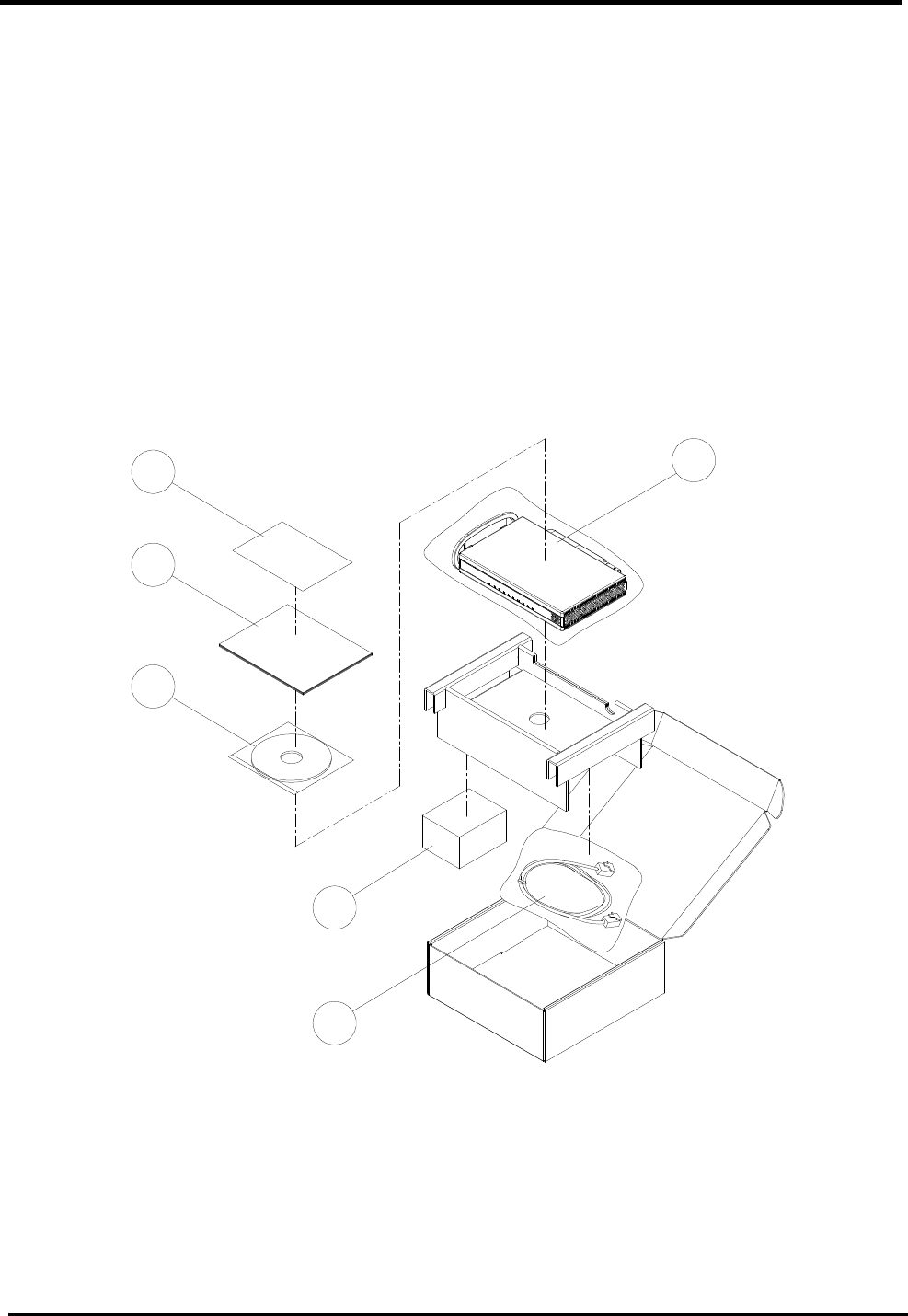
2. Installation
2.1. In The Box
In addition to this document, the WiMAX modem should come with the following:
1. Warranty Card x 1
2. Quick Installation Guide x 1
3. CD-ROM x 1
4. WM5347N x 1
5. Power Adaptor x 1
6. Ethernet Cable x 1
01 04
05
02
03
06
Figure 1. Device Installation
WM5347N User Manual
3
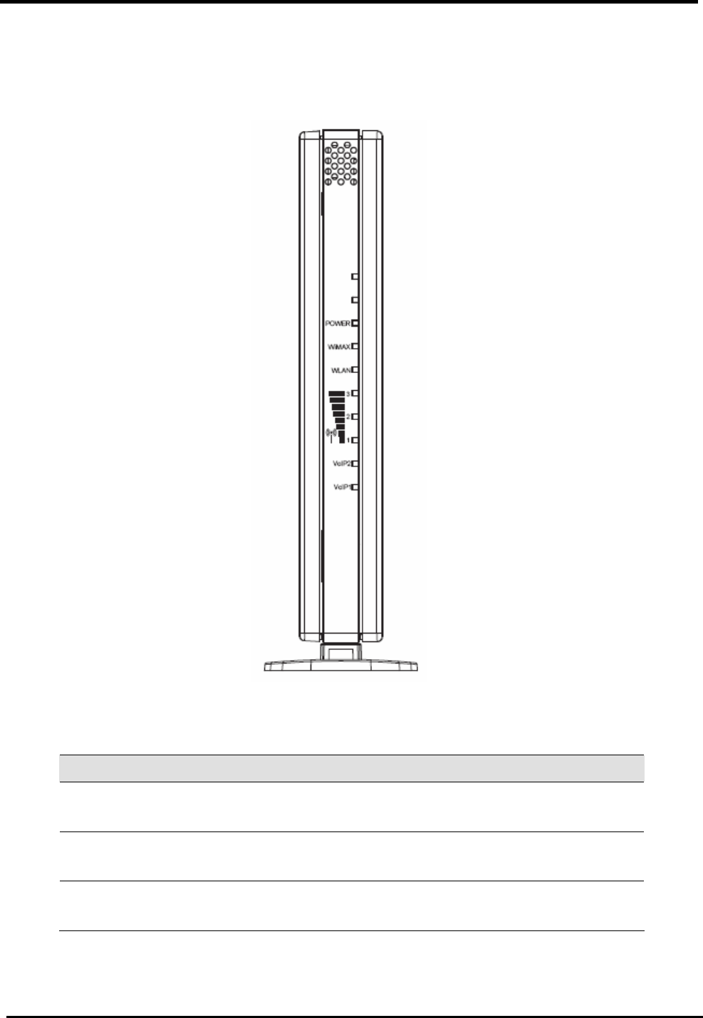
2.2. Indicators
LEDs on the front panel indicate the status of WiMAX modem (see Figure 2).
Figure 2. Device Front Panel
Label Color Function
Power Green On: Unit is powered on
Off: Unit is powered off
WiMAX Orange On: WAN is active
Off: No WAN link
WLAN Green On: WIFI is enabled
Off: WIFI is disabled
WM5347N User Manual
4
Green Signal strength of the WiMAX
VoIP1 / VoIP2 Green On: Registered on server
Off: Non-register
LAN1 / LAN2 Green On: LAN connected
Blinking: Data transfer
Off: No connection
Note: LAN LED’s are on RJ-45 connectors.
Table 1. Illustration of WM5047 Front Panel
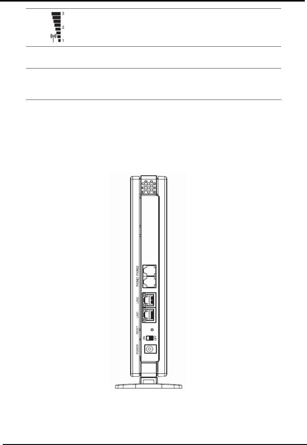
2.3. Connectors
Ports on the rear panel for WiMAX modem are for data and power connections (see Figure 3).
Figure 3. Device Pear Panel

WM5347N User Manual
5
Label Function
LAN1, LAN2 RJ-45 connector: Connect device to PC’s Ethernet port, or to
the uplink port on LAN hub, using the cable provided.
PHONE1,
PHONE2 RJ-11 connector: Connect device to telephone port using the
cable provided.
RESET Press 5 seconds to return device to Factory Default Setting.
ON / OFF Power ON / OFF the modem.
POWER Connect to the supplied power adapter cable.
Table 2. Illustration of Device Rear Panel
WARNING
Before you start, switch off all
devices.
These include the User computer(s),
User LAN hub /switch (if applicable),
and WiMAX modem.
WM5347N User Manual
6
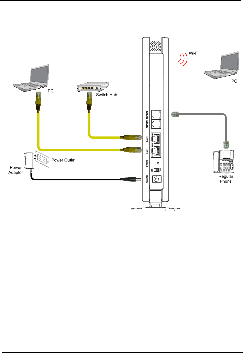
2.4. Network Connection
Figure 4 illustrates the hardware connections. The layout of the parts on the device may differ from
the layout shown. Refer to the steps below for specific instructions.
Figure 4. Overview of Hardware Connections
Step 1. Connect Ethernet cable.
If user is connecting WiMAX modem to LAN, attach one end of the Ethernet cable to a regular hub
port or PC, and the other to the Ethernet port on WiMAX modem.
Step 2. Attach power connector.
Connect AC power adapter plug to DC 12V connector on the back of the WiMAX modem and plug
power adapter into a wall outlet or power strip.
Step 3. Turn the power switch to ON.
Turn the power switch to ON.

WM5347N User Manual
7
Step 4. Configure WiMAX modem through WEB interface
The detail for Step 4 will be described in Chapter 3. It will help user to configure the WiMAX modem
based on user needs.
Step 5. Save the configurations and Reboot.
All the settings that user makes on the WiMAX modem will take effect after rebooting.
WM5347N User Manual
8
3. Introduction
The CPE Software platform comes from with a Web-based Configuration Manager, which gives
users the ability to manage, configure and analyze the platforms environment. The Connection
Manager works with all versions of Windows after Windows 95.
The supported browser version:
Internet Explorer 6.0 or later (Recommended)
Netscape 7.1 and higher
Firefox 1.0 and higher
Mozilla 1.5 and higher
3.1. Connect
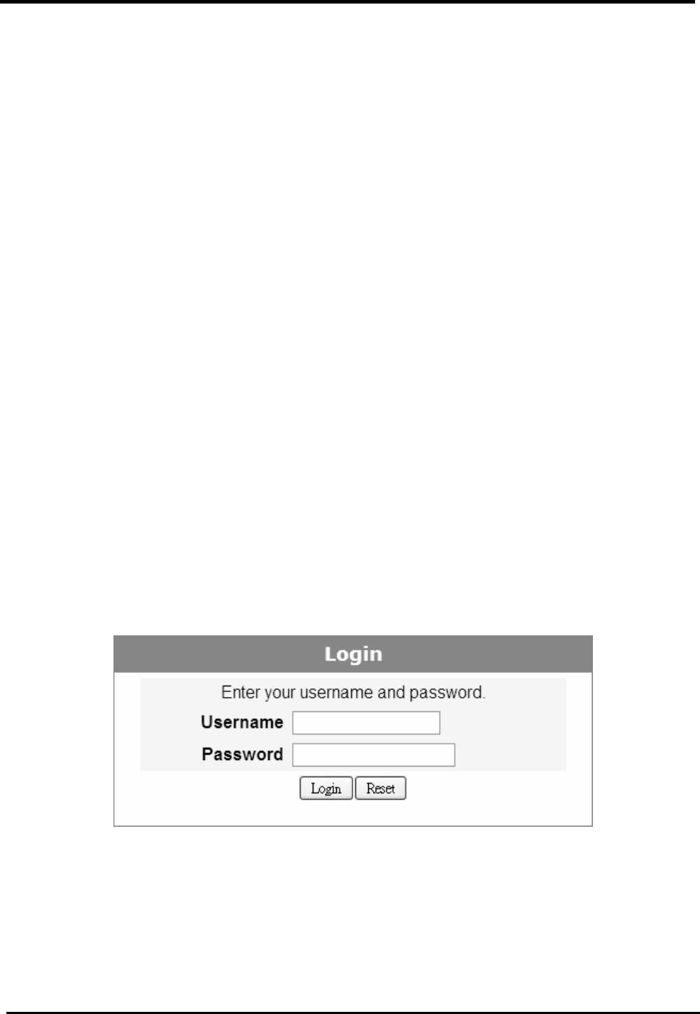
User need to connect to the CPE platform properly. It’s assumed that the user has a fully working
CPE platform and properly connected. From the web browser, connect to the device by entering the
IP address of the device; it will prompt you to enter your username and password. The default
usernames and passwords are as follows:
Username/password
admin/admin
guest/guest
Figure 5. Login
WM5347N User Manual
9
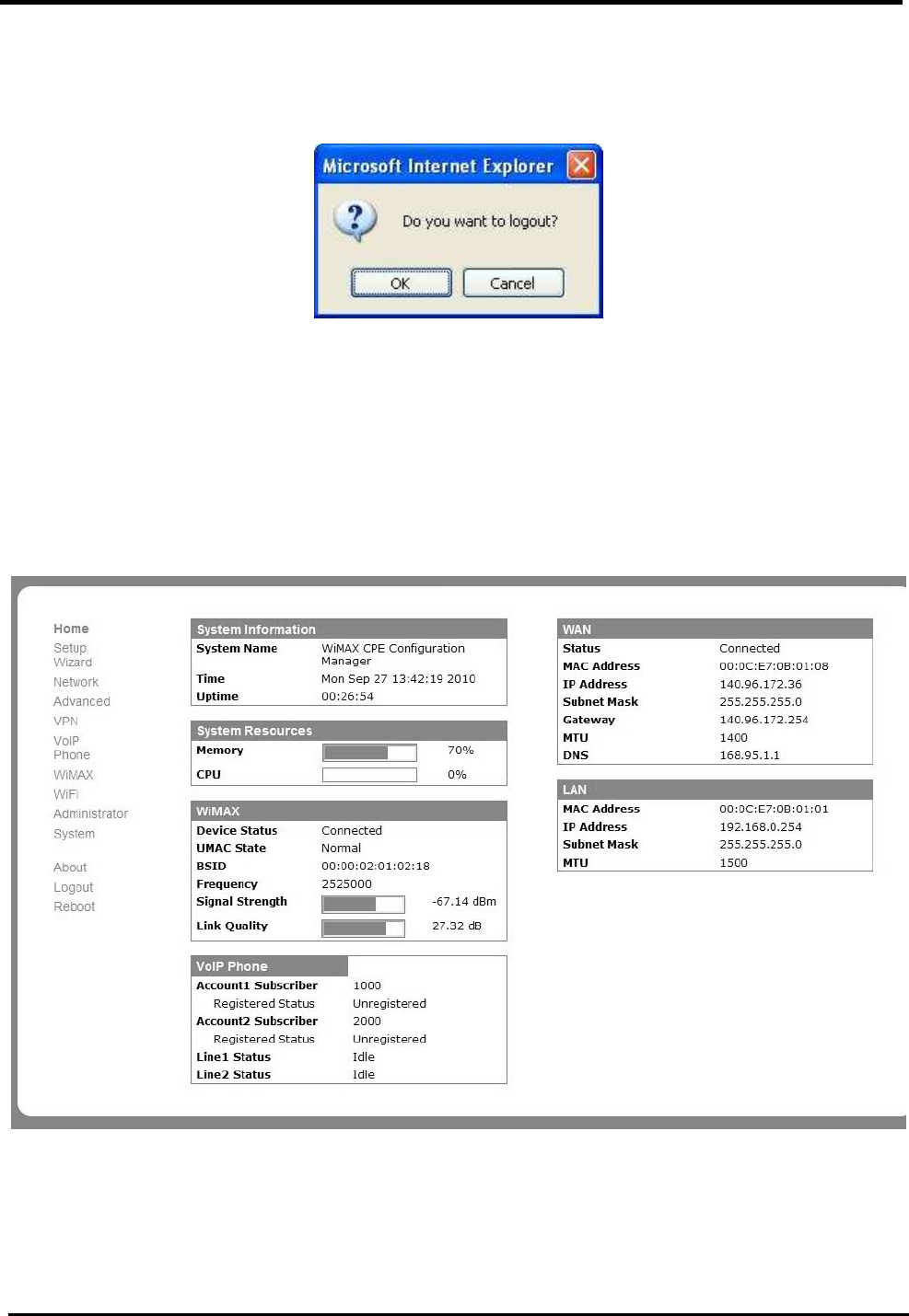
3.2. Logout
The “Logout” window allows users to disconnect from the device and exit the Web-based
Configuration Manager.
Figure 6. Logout
3.3. Home
After you’ve established a connection, you will see the “Home” window. This window shows all the
settings as they currently are configured and system information. It gives you an initial overview of
the current status of your device.
Figure 7. Home

WM5347N User Manual
10
3.4. About
The “About” window will show you pertinent version information on the CPE.
Figure 8. About CPE Configuration Manager
WM5347N User Manual
11
4. Wizard
The wizard will allow you to quickly configure the basic networking settings on the CPE. Click the
“Wizard” menu item to enter the wizard. The first page will display all the steps necessary to
complete the wizard settings. Click the “Next” button to continue to the next step.
Name Description
Next Continue to the next step.
Back Return to the previous step.
Save Commit the changes mad and save to CPE device.
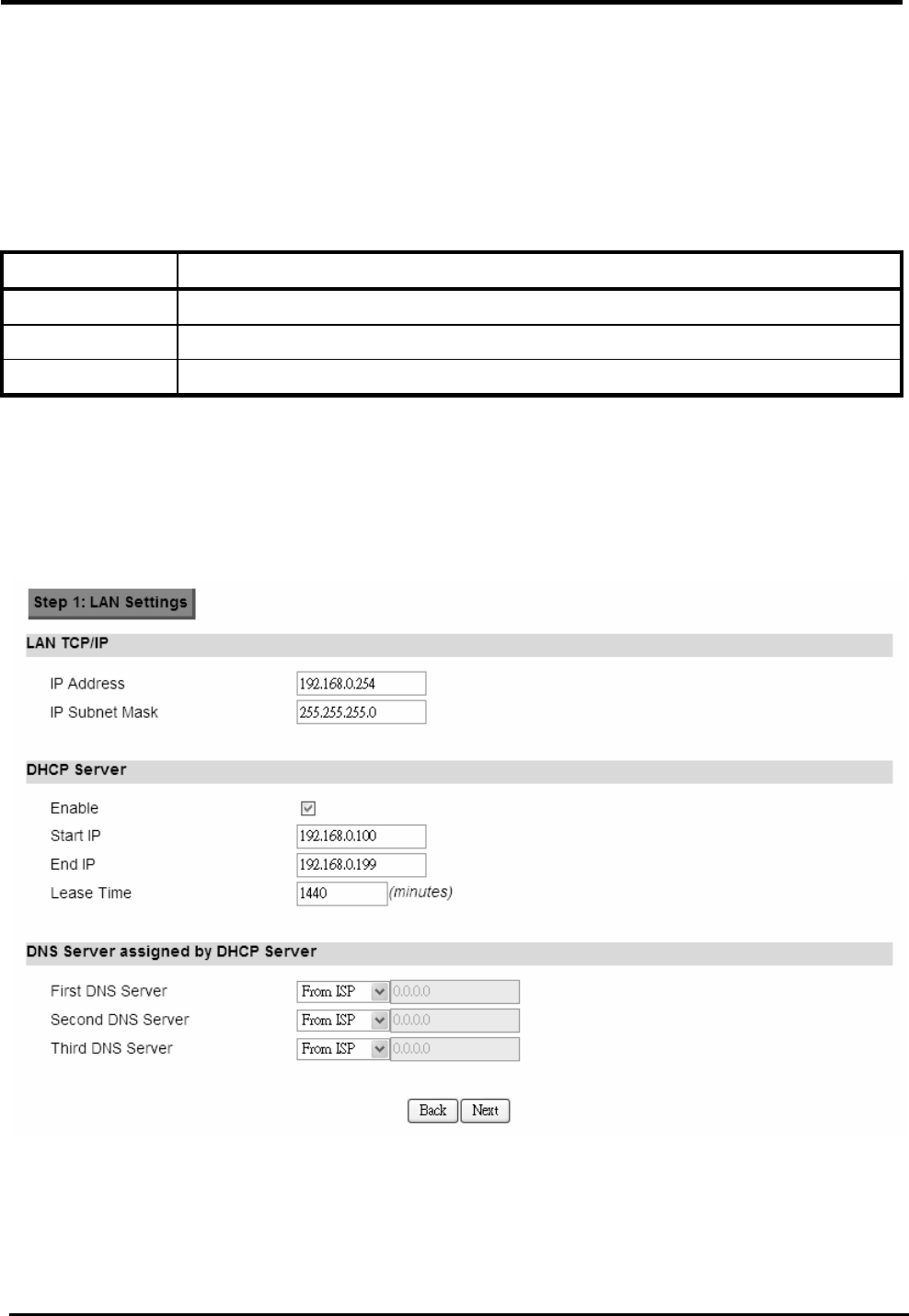
Step 1: LAN Settings. In this step you can configure both IP and DHCP configuration
parameters.
Figure 9. Wizard LAN Settings
WM5347N User Manual
12
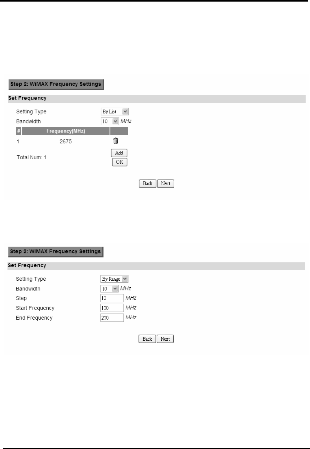
Step 2: WiMAX Frequency Settings. This step will quickly configure the WiMAX
frequencies. You have two forms of configuring the frequency. You can configure it
through simply entering a frequency list or by setting a range, by giving a starting and
ending frequency value and a step size to traverse the range.
Figure 10. Wizard WiMAX Frequency (By List)
Figure 11. Wizard WiMAX Frequency (By Range)
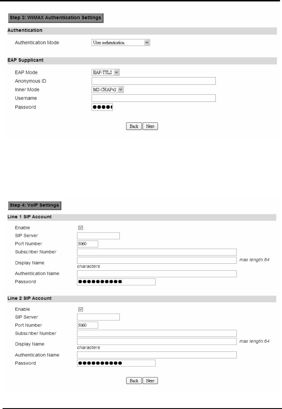
Step 3: WiMAX Authentication Settings. This will configure WiMAX Authentication
settings. There are 4 possible options for “Authentication Mode”. Depending on which
mode you select, you will have different EAP settings to configure.
WM5347N User Manual
13
Figure 12. Wizard WiMAX Authentication Settings
Step 4: VoIP Settings. This step will configure VoIP.
Figure 13. Wizard VoIP Settings
WM5347N User Manual
14
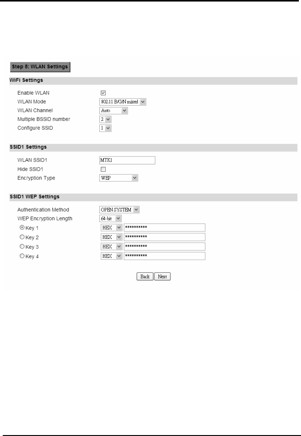
Step 5: Configures WLAN settings. See section WiFi WLAN for complete details on
WLAN setting parameters. Depending on which encryption type you select, you will get
corresponding attributes to configure for that encryption type.
Figure 14. Wizard WLAN Settings
Once you’ve completed all the steps, you need to click on the “Save” button to save the settings, or
click on “Back” to return to the previous step. It will reload some services and return to the “Home”
window.

WM5347N User Manual
15
Figure 15. Wizard Save
WM5347N User Manual
16
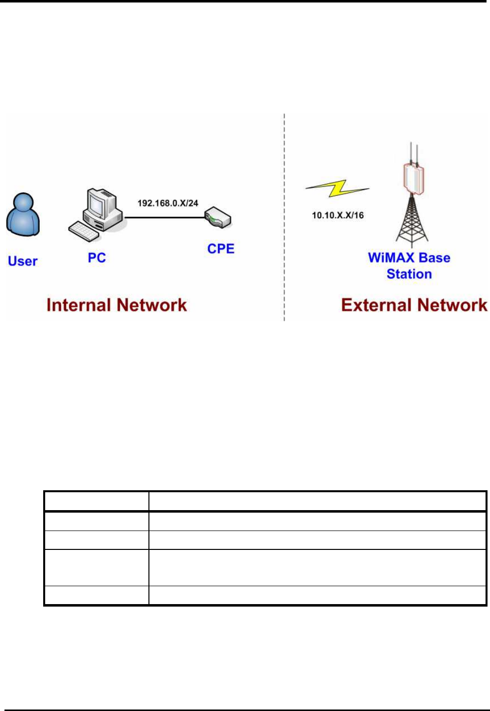
5. Network
Refer to Figure 12, for proper network connection.
Figure 16. Network Topology
5.1. LAN
5.1.1. IP
From the “Network>LAN>IP” window, you can update the LAN information.
Name Description
IP Address IP address of the CPE device.
IP Subnet Mask Subnet Mask of the CPE device.
Save Commit the changes made, and set the LAN IP information,
some services will be reloaded.
Cancel Reset fields to the last saved values.

WM5347N User Manual
17
Figure 17. Network>LAN>IP
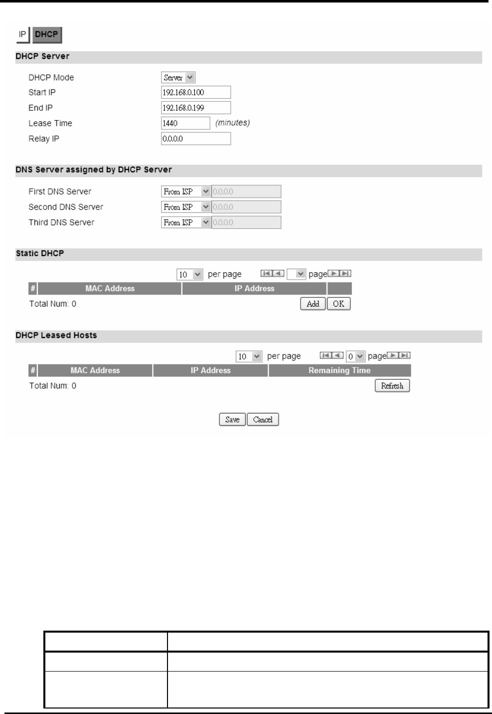
5.1.2. DHCP
Use the “Network>LAN>DHCP” tab to configure the DHCP server information. There are three DNS
servers the user can configure to assign an IP address. Static DHCP will assign an IP address on
the LAN to a specific device based on its MAC address.
“Network>LAN>DHCP”
Name Description
DHCP Server
DHCP Mode None
Server
Relay
When Server mode is selected, the DHCP server will
assign IP address to its client with the specified IP
address range.
When Relay IP mode is selected, you need to assign a
DHCP relay agent in “Relay IP” column.
Start IP Starting IP address range.
End IP Ending IP address range.
Lease Time The lease time is a controlled time period, allowing the
DHCP server to reclaim (and then reallocate) IP
addresses that are not renewed (dynamic re-use of IP
addresses) Lease time is measured in minutes in the
Configuration Manager.
Relay IP User needs to assign a DHCP relay agent IP address,
when “Relay mode” selected.
DNS Server assigned
First DNS Server You can specify three DNS server and select how the

WM5347N User Manual
18
Second DNS Server
Third DNS Server
DNS Server is assigned. There are three options for
assigning the DNS server:
From ISP
User Defined
None
If User selects “None”, then the DHCP server will not give
clients the DNS server information. If all the three DNS
servers setting are set to “None”, then the DHCP server
will use the LAN IP address as the DNS server
information for the clients. If the user chooses “User
Defined” and leaves the IP address as “0.0.0.0” it will
change the field to “None”.
Static DHCP
Add Click on the “Add” button, to enter a static leased IP
address. Enter the MAC address of the Ethernet device
and enter the IP address.
OK Click the “OK” button to exit the table edit mode.
DHCP Leased Hosts
Refresh Click the “Refresh” button to refresh DHCP leased hosts
information.
Save Commit the changes made, and save to CPE device,
some services will be reloaded.
Cancel Reset fields to the last saved values.
WM5347N User Manual
19
Figure 18. Network>LAN>DHCP
5.2. WAN
The wide area network is another network that you can connect to the internet with the CPE device.
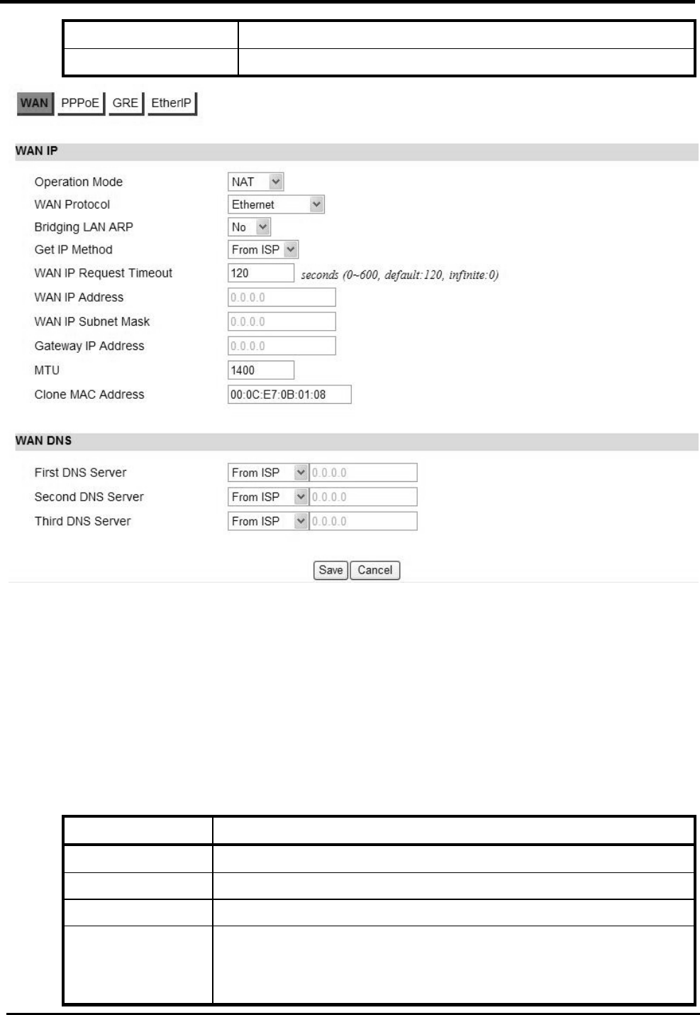
5.2.1. WAN
“Network>WAN>WAN”
Name Description
WAN IP
Operation Mode Here provides three operation modes:
Bridge

WM5347N User Manual
20
Router
NAT
WAN Protocol Please base on ISP provides connection method to select
one protocol for network connection.
Ethernet
PPPoE
GRE Tunnel
EtherIP Tunnel
Bridging LAN ARP Bridging LAN ARP:
Yes
No
Get IP Method Enter the IP gotten method:
From ISP
User
WAN IP Request
Timeout
The time the DHCP client waits to receive the IP address
from the BS. If it doesn’t get the IP it will timeout and the
CPE will disconnect the WiMAX connection. The default
value is 120 seconds. If you enter 0, will wait to receive the
IP address infinitely until it’s stopped by the user.
WAN IP Address If you chose “User” for IP Method, enter the WAN IP
address.
WAN IP Subnet
Mask
If you chose “User” for IP Method, enter the WAN IP
subnet Mask.
Gateway IP Address
If you chose “User” for IP Method, enter the IP gateway
address.
MTU Enter the MTU.
Clone MAC Address
Clone MAC address of WAN port.
WAN DNS
First DNS Server Enter the WAN DNS information.
User Defined
From ISP
If you select “User Defined”, you need to enter a valid IP
address for the DNS server.
Second DNS Server See First DNS Server.
Third DNS Server See First DNS Server.
Save Commit the changes made, and save to CPE device, after
clicking the Save button you will get a message asking if
you want to reboot the CPE. Reboot is required so the
WM5347N User Manual
21
device can switch to a different profile.
Cancel Reset fields to the last saved values.
Figure 19. Network>WAN>WAN
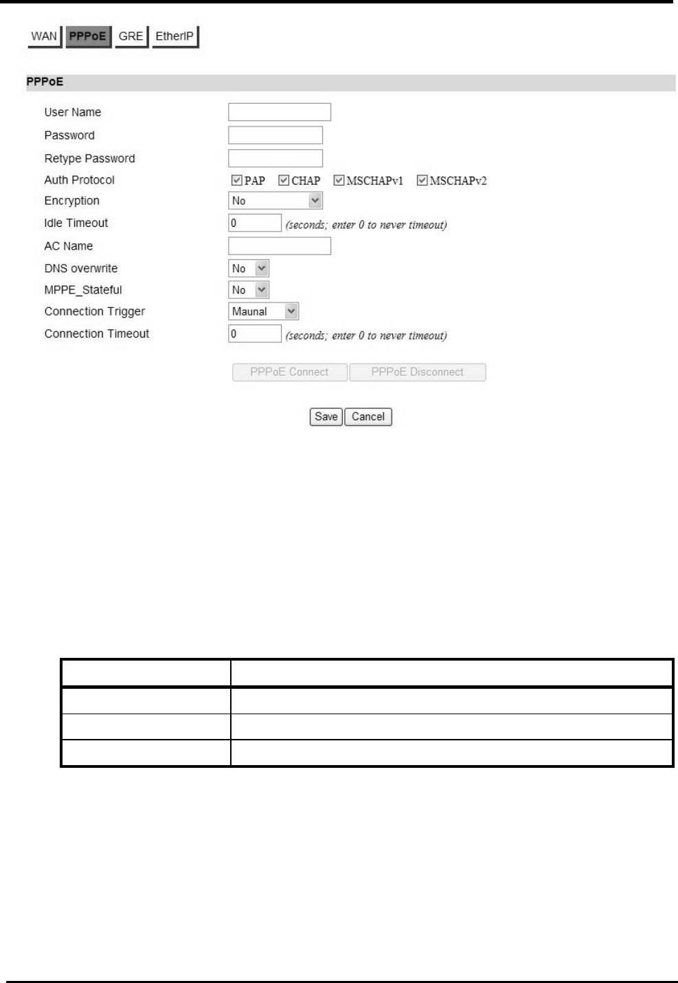
5.2.2. PPPoE
Before you configure PPPoE, you need to set “WAN” Protocol to “PPPoE” in WAN page.
“Network>WAN>PPPoE”
Name Description
User Name Enter the username.
Password Enter the password.
Retype Password
Enter the password again.
Auth Protocol Require the peer to authenticate itself before allowing network
packets to be sent or received. We support the following
protocol:

WM5347N User Manual
22
PAP: Password Authentication Protocol.
CHAP: Challenge Handshake Authentication Protocol.
MSCHAP: Microsoft Challenge Handshake Authentication
Protocol.
MSCHAPv2: Microsoft Challenge Handshake Authentication
Protocol, Version2.
Encryption Encryption Scheme:
None:
MPPE 40 bits: 40-bit encryption with MPPE.
MPPE 128 bits: 128-bit encryption with MPPE.
Auto: automatically select encryption scheme.
Idle Timeout Disconnect if the link is idle for the assigned seconds.
AC Name AC name.
DNS overwrite DNS overwrite.
MPPE_Stateful MPPE Stateful.
Connection
Trigger
Connection Trigger Model:
AlwaysOn: Trigger connection automatically.
Manual: Trigger connection by manual.
Connection
Timeout
Connection timeout.
PPPoE Connect Click this button to connect network.
PPPoE
Disconnect
Click this button to disconnect network.
Save Commit the changes made and save to CPE device.
Cancel Reset fields to the last saved values.
WM5347N User Manual
23
Figure 20. Network>WAN>PPPoE
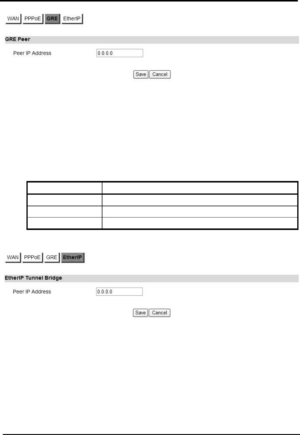
5.2.3. GRE
Before you configure GRE, you need to set “WAN Protocol” to “GRE Tunnel” in WAN page.
“Network>WAN>GRE”
Name Description
Peer IP Address Enter IP address.
Save Commit the changes made and save to CPE device.
Cancel Reset fields to the last saved values.
WM5347N User Manual
24
Figure 21. Network>WAN>GRE
5.2.4. EtherIP
Before you configure EtherIP, you should set “WAN Protocol” to “EtherIP Tunnel” in WAN tag.
“Network>WAN>EtherIP”
Name Description
Peer IP Address Enter IP address.
Save Commit the changes made and save to CPE device.
Cancel Reset fields to the last saved values.
Figure 22. Network>WAN>EtherIP

WM5347N User Manual
25
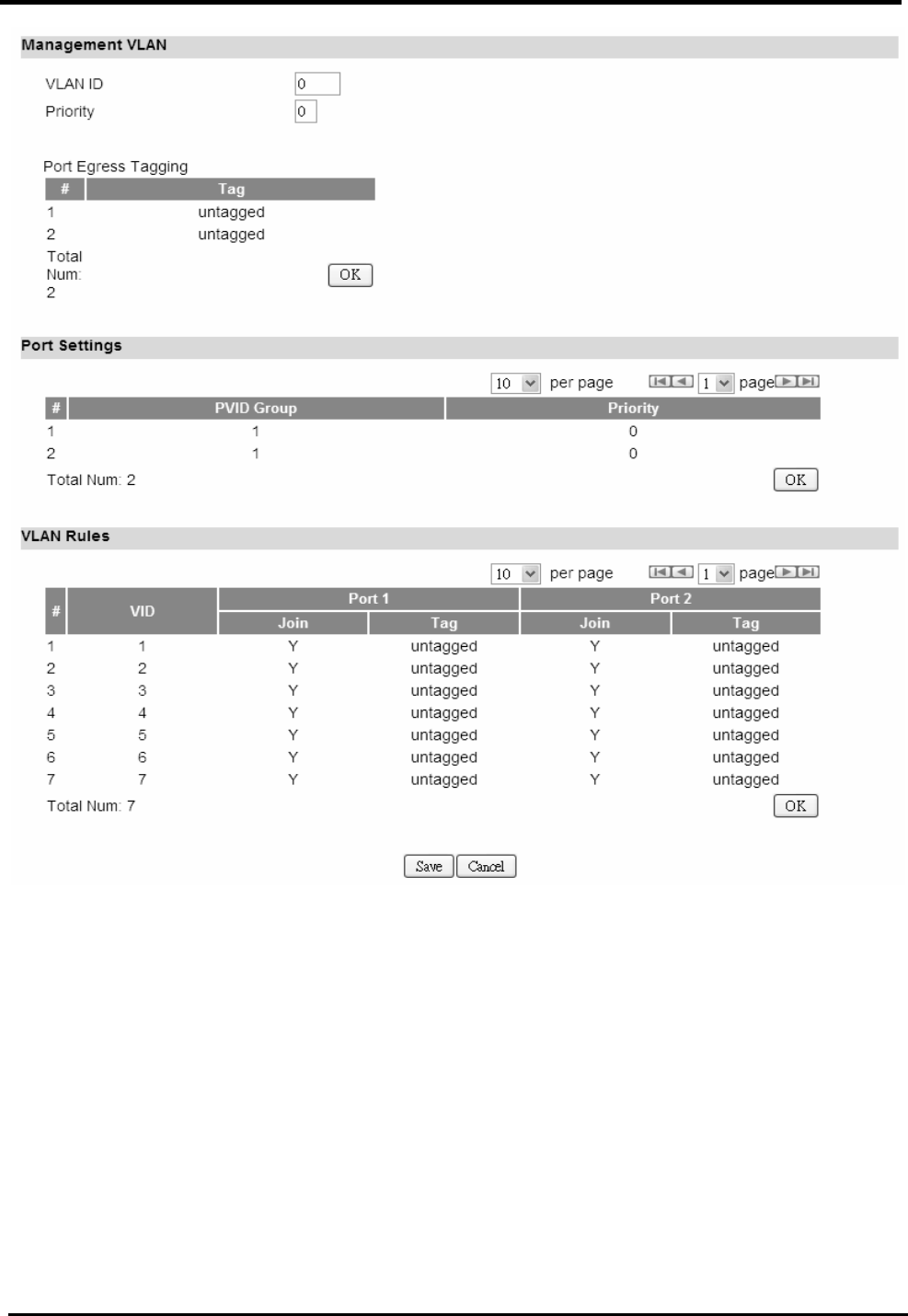
5.3. VLAN
“Network>VLAN”
Name Description
Management VLAN
VLAN ID Setting the management VLAN ID.
Priority Setting the management Priority.
Port Settings
PVID Group Select the VLAN group as the PVID
Priority Setting the port Priority.
VLAN Rules
VID Setting the VID of this group.
Join Add this port into this group.
Tag Mark the out-going packets of this port in this VLAN as
tagged or untagged.
Save Commit the changes made and save to CPE device
Cancel Reset fields to the last saved values
WM5347N User Manual
26
Figure 23. Network>VLAN

WM5347N User Manual
27
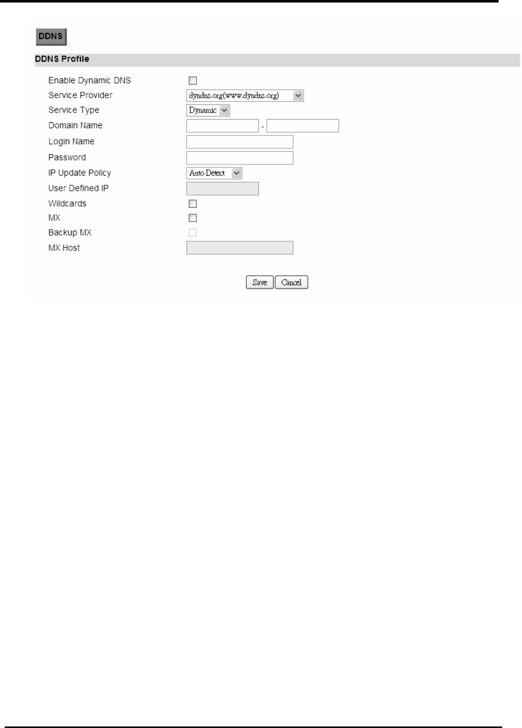
5.4. DDNS
“Network>DDNS”
Name Description
Enable Dynamic DNS Click the check box to enable dynamic DNS.
Service Provider Enter the URL of the service provider.
Service Type* Enter the service type (DYNDNS only)
Dynamic
Static
Custom
Domain Name Enter the domain name.
Login Name Enter the username.
Password Enter the password.
IP Update Policy Select the Policy to be used:
Auto Detect
WAN IP
User Defined
User Defined IP If you selected “User Defined” ad the IP policy, then enter
the IP address.
Wildcards* Allows hostname to use wildcards such as “*”. It will allow
“*hos.dyndns.org” to be aliased to the same IP address
as “host.hyndns.org”.
MX* Enable mail routing.
Backup MX* Enable Second mail routing.
MX Host* Host where mail will be routed to.
Save Commit the changes made and save to CPE device.
Cancel Reset fields to the last saved values.
NOTE: * Supported by DYNDNS service provider
WM5347N User Manual
28
Figure 24. Network>DDNS

WM5347N User Manual
29
6. Advanced Setting
The “Advanced Settings” window will allow you to set rules for incoming and outgoing traffic.
6.1. NAT
Network Address Translation (NAT) is the process of modifying the network address information
of the host in a packet while in transit, so that it can be remapped to a given address space in
another network. For example, the source address of a packet in a network is changed to a different
IP address known within another network.
6.1.1. Port Forward
The “Advanced>NAT>Port Forward” tab is used to create “Port Forward” rules based on protocol
port. Click the “Add” button to add a Port Forward rule.
“Advanced>NAT>Port Forward”
Name Description
Activate Check the box to activate the “Port Forward” rule.
Name Name of the Port Forward rule.
Protocol Which Protocol to be matched by the rule? Available
options are: TCP, UDP, or TCP/UDP.
Incoming Port(s) Which port range to be matched by the Port Forward rule?
Enter the starting and ending port range.
Forward Ports(s) Which port range will be translated to if it matches the rule?
The packet will be forwarded to one of these ports if it
matches the rule. Enter the starting and ending port range.
Server IP Which IP address will be translated to if it matched the
rule? The packet will be forwarded to this IP address if it
matched the rule.
Trash Delete the Port Forward rule.
Add Click the “Add” button to create a new Port Forward rule.
Wizard The wizard will allow you to quickly configure Port Forward
rule.
OK Click the “OK” button to exit the table edit mode.
Save Commit the changes made and save to CPE device.
Cancel Reset fields to the last saved values.

WM5347N User Manual
30
Figure 25. Advanced>NAT>Port Forward
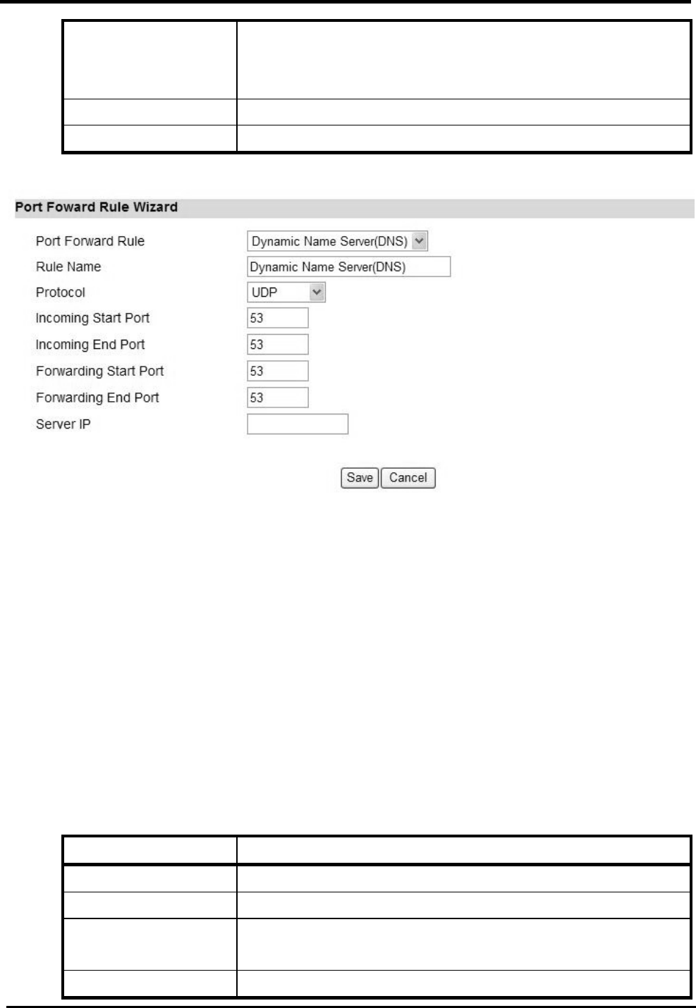
“Advanced>NAT>Port Forward>Wizard”
Name Description
Port Forward Rule Select one protocol for Port Forward Rule:
Dynamic Name Server (DNS)
FTP Server
IPSEC
Mail(POP3)
Mail(SMTP)
PPTP
RealPlayer 8 Plus
SSH
SNMP
SNMP Trap
Telnet Server
TFTP
Rule Name Name of the Port Forward rule.
Protocol Which Protocol to be matched by the rule? Available
options are: TCP, UDP, or TCP/UDP.
Incoming Start and
End Port(s)
Which port range to be matched by the Port Forward rule?
Enter the starting and ending port range.
Forwarding Start and
End Ports(s)
Which port range will be translated to if it matches the rule?
The packet will be forwarded to one of these ports if it
matches the rule. Enter the starting and ending port range.
WM5347N User Manual
31
Server IP Which IP address will be translated to if it matched the
rule? The packet will be forwarded to this IP address if it
matched the rule.
Save Commit the changes made and save to CPE device.
Cancel Reset fields to the last saved values.
Figure 26. Advanced>NAT>Port Forward>Wizard
6.1.2. Port Trigger
The “Advanced>NAT>Port Trigger” tab allows you to configure Port Trigger rules. Port Trigger is a
way to automate port forwarding in which outbound traffic on predetermined ports (“trigger port”)
causes inbound traffic to specific incoming ports to be dynamically forwarded to the initiating host,
while the outbound ports are in use. This allows users behind CPE on the LAN to provide services
that would normally require the computer to have IP address on the LAN. Port triggering triggers an
open incoming port (‘open port’) when a client on the local network makes an outgoing connection
on a predetermined port or range of ports.
“Advanced>NAT>Port Trigger”
Name Description
Activate Check the box to activate the “Port Trigger” rule.
Name Name of the Port Trigger rule.
Protocol Which Protocol the outgoing packet used will trigger the
rule? Available options are: TCP, UDP, or TCP/UDP.
Trigger Port(s) Which ports range the outgoing packet will trigger the rule?

WM5347N User Manual
32
Enter the starting and ending port range.
Open protocol Which protocol will be opened if the rule had been
triggered? Available options are: TCP, UDP or TCP/UDP.
Trash Delete the Port Trigger rule.
Wizard The wizard will allow you to quickly configure Port Forward
rule.
Add Click the “Add” button to create a new Port Trigger rule.
OK Click the “OK” button to exit the table edit mode.
Save Commit the changes made and save to CPE device.
Cancel Reset fields to the last saved values.
Figure 27. Advanced>NAT>Port Trigger
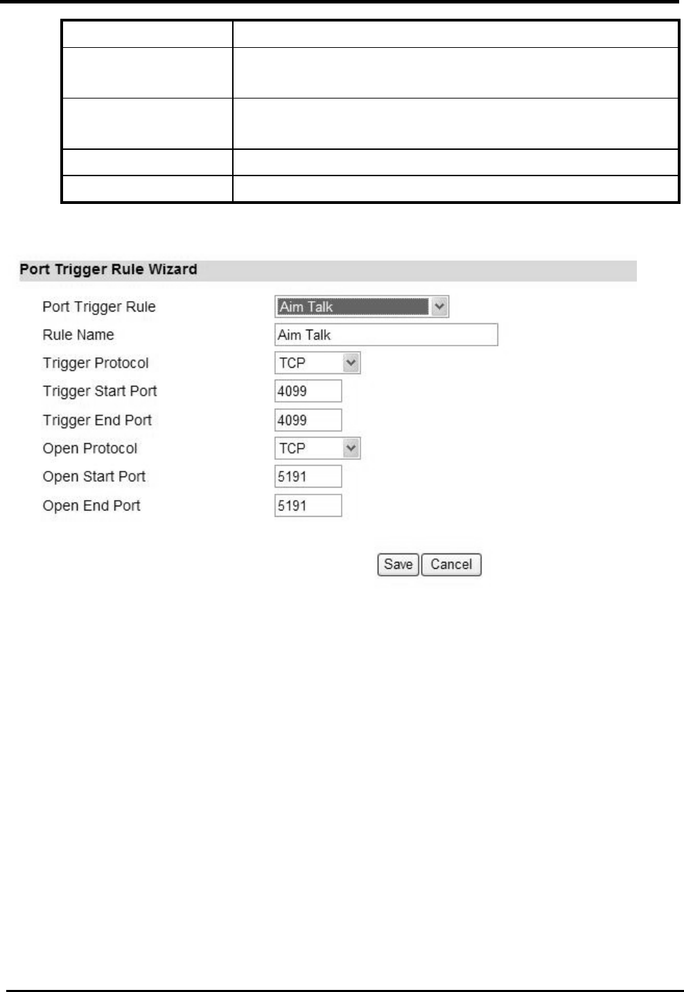
“Advanced>NAT>Port Trigger>Wizard”
Name Description
Port Trigger Rule Select one application for Port Trigger Rule:
Aim Talk
Asheron’s Call
Calista IP Phone
Net2Phone
RainboxSix/Rogue Spea
Rule Name Name of the Port Trigger rule.
Trigger Protocol Which Protocol the outgoing packet used will trigger the
rule? Available options are: TCP, UDP, or TCP/UDP.
Trigger Start and Which ports range the outgoing packet will trigger the rule?
WM5347N User Manual
33
End Port Enter the starting and ending port range.
Open protocol Which protocol will be opened if the rule had been
triggered? Available options are: TCP, UDP or TCP/UDP.
Open Start and End
Port
Which ports range of the protocol will trigger the rule?
Enter the starting and ending port range.
Save Commit the changes made and save to CPE device.
Cancel Reset fields to the last saved values.
Figure 28. Advanced>NAT>Port Trigger>Wizard
6.1.3. DMZ
The “Advanced>NAT>DMZ” tab allows you to configure a DMZ (Demilitarized Zone) host IP
address. Enter the IP address of the DMZ host. The “Save” button will save the changes to CPE
device and the “Cancel” button will reset the field to last saved value. Enter “0.0.0.0” to disable DMZ
host.

WM5347N User Manual
34
Figure 29. Advanced>NAT>DMZ
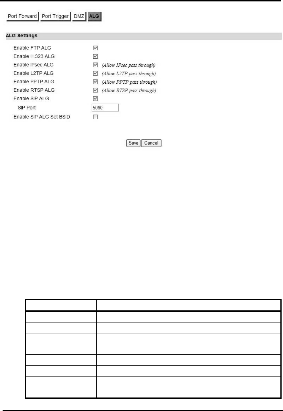
6.1.4. ALG
There are three ALGs you can enable from “Advanced>NAT>ALG” tab. ALG allows legitimate
application traffic to pass through the CPE device that would have otherwise been restricted. Without
ALGs, some application may not work well because of NAT/firewall settings. Click on the check box
to enable ALGs.
NOTE: If you are using any of these types of application protocols you need to enable them in the
ALG settings.
Enable FTP ALG
Enable H.323 ALG
Enable IPsec ALG
Enable L2TP ALG
Enable PPTP ALG
Enable RTSP ALG
Enable SIP ALG
Enable SIP ALG set BSID
WM5347N User Manual
35
Figure 30. Advanced>NAT>ALG
6.2. Firewall
In networking, firewalls are used to block un-wanted traffic or prevent from DDoS attacks. It will
prevent unauthorized devices to enter a trusted network.
6.2.1. IP Filter
The IP filter rules will drop or discard traffic that fits the filter criteria.
“Advanced>Firewall>IP Filter”
Name Description
Activate Check the box to activate the “IP Filter” rule.
Source IP/Mask Source IP to filter on and mask.
Source Port Source port to filter on.
Destination IP/Mask Destination IP to filter on and mask.
Destination Port Destination port to filter on.
Protocol Protocol to filter on.
Trash Delete the IP Filter rule.
Add Click the “Add” button to create a new IP Filter rule.

WM5347N User Manual
36
OK Click the “OK” button to exit the table edit mode.
Save Commit the changes made and save to CPE device.
Cancel Reset fields to the last saved values.
Figure 31. Advanced>Firewall>IP Filter
6.2.2. MAC Filter
“Advanced>Firewall>MAC Filter”
Name Description
MAC List
Blacklist/Whitelist Select Blacklist or Whitelist.
MAC Filter Rules
Activate Check the box to activate the “MAC Filter” rule.
Source MAC Source MAC to filter on and mask.
Destination MAC Destination MAC to filter on and mask.
Mon ~ Sun
Start Time ~ End Time
You can select days of week, and setup the “Start Time”
and “End Time” for MAC filter.
Add Add a new MAC filter rule.
OK Click the “OK” button to exit the table edit mode.
Save Commit the changes made and save to CPE device.
Cancel Reset fields to the last saved values.

WM5347N User Manual
37
Figure 32. Advanced>Firewall>MAC Filter
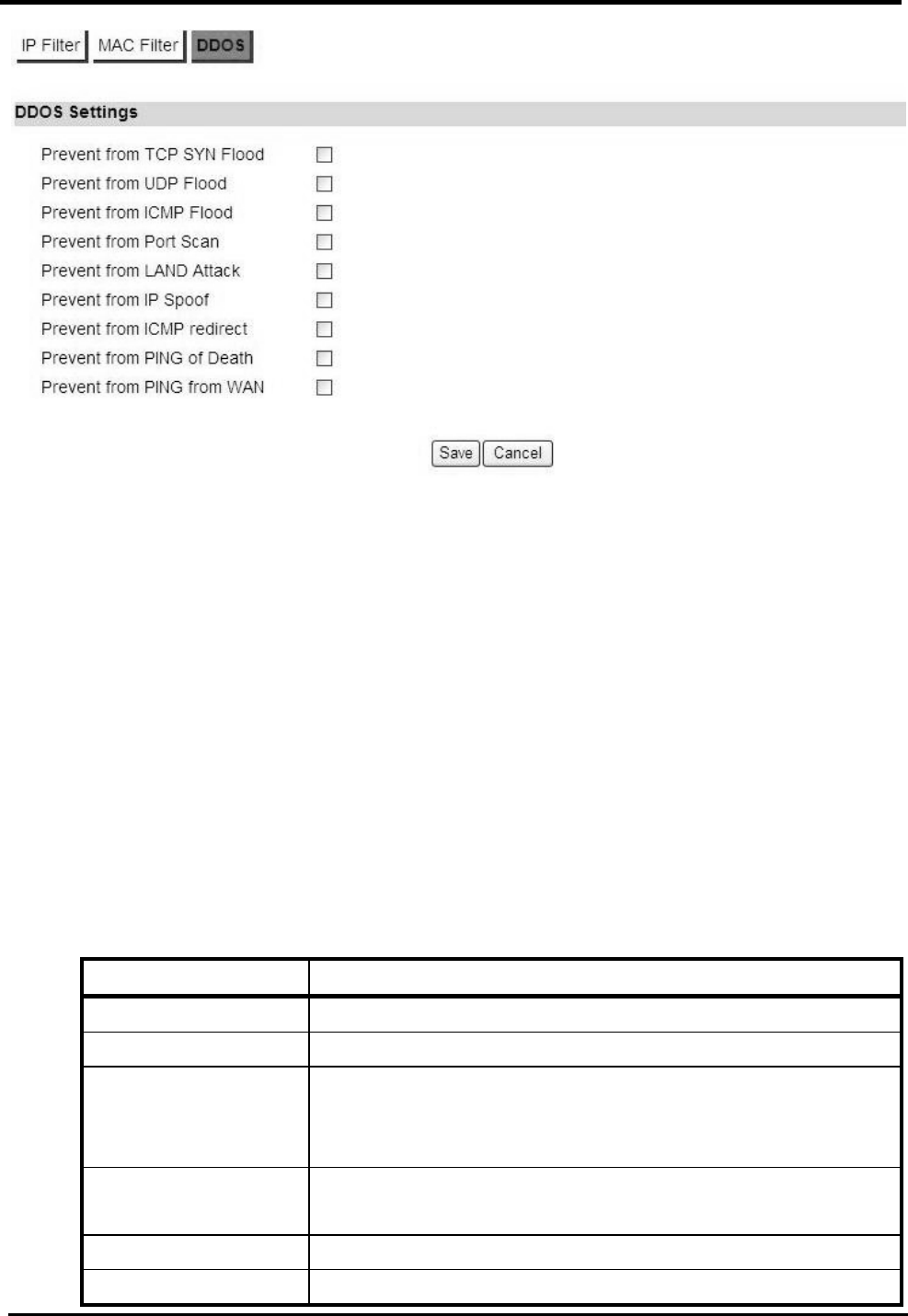
6.2.3. DDOS
“Advanced>Firewall>DDOS”
Name Description
TCP SYN Flood It will prevent SYN flood from WAN or LAN.
UDP Flood It will prevent UDP flood to CPE device.
ICMP Flood It will prevent ICMP flood from WAN or LAN.
Port Scan It will prevent port scanning from WAN and issue an alarm
entry in the system log.
LAND Attack It will prevent LAND attack.
IP Spoof It will prevent IP spoof attack.
ICMP redirect It will prevent ICMP redirect attack.
PING of Death It will prevent ping of death attack.
PING from WAN It will ping from WAN.
Save Commit the changes made and save to CPE device.
Cancel Reset fields to the last saved values.
WM5347N User Manual
38
Figure 33. Advanced>Firewall>DDOS
6.3. Route
A route is a path in the network, which can direct the flow of network traffic.
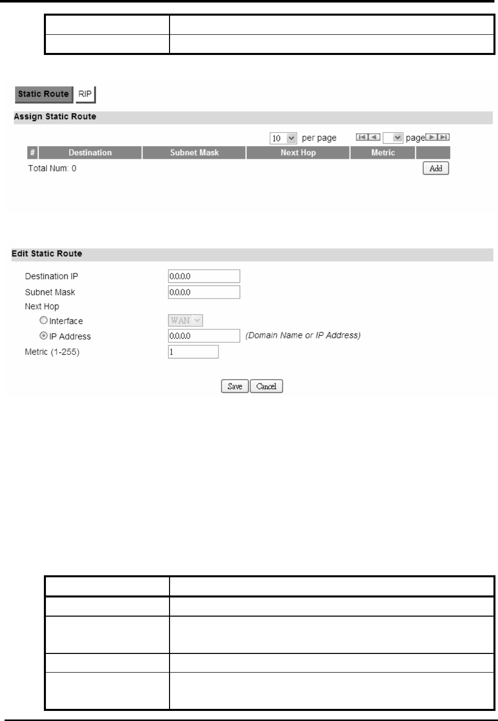
6.3.1. Static Route
The static route is a hard coded path in the router that specifies how it will get to a certain subnet by
using a defined path.
“Advanced>Route>Static Route”
Name Description
Destination IP Enter the Destination IP address you would like to reach.
Subnet Mask Enter the subnet mask.
Next Hop Select where the next hop will be.
WAN or LAN interface directly
IP Address
Metric Enter the metric value, “cost” of transmission for routing
purposes.
Trash Will remove the selected route.
Add Will enter in edit mode to add a static route.
WM5347N User Manual
39
Save Commit the changes made and save to CPE device.
Cancel Reset fields to the last saved values.
Figure 34. Advanced>Route>Static Route
Figure 35. Advanced>Route>Static Route>Add
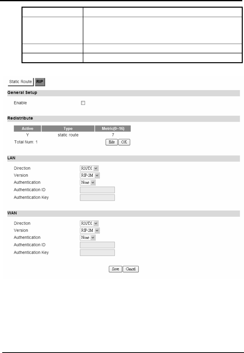
6.3.2. RIP
The Routing Information Protocol (RIP) is a dynamic routing protocol used in local area networks.
It allows a router to exchange routing information with other routers.
“Advanced>Route>RIP”
Name Description
General Setup
Enable Click the enable check box will activate the RIP routing
rule.
Redistribute
Edit Click “Edit” button to activate the static route or change the
metric value. The static route refers to the static routes

WM5347N User Manual
40
defined in Advanced>Route>Static Route window.
OK Click the “OK” button to exit edit table mode.
LAN
Direction None
RX
TX
RX/TX
Version If you select “RX, TX or RX/TX” for Direction you will get
the following RIP version options available.
RIP-1
RIP-2B
RIP-2M
Authentication If you select “RIP-2B or RIP-2M” for Version, you will get
the following Authentication options.
None
Text
MD5
Authentication ID If you select “MD5” for Authentication type, you can enter
the authentication ID and Key.
Authentication Key If you select “Text” for Authentication you can enter a text
authentication key. If you select “MD5” for Authentication
type, you also need to enter an Authentication ID and Key.
WAN
Direction None
RX
TX
RX/TX
Version If you select “RX, TX or RX/TX” for Direction you will get
the following RIP version options available.
RIP-1
RIP-2B
RIP-2M
Authentication If you select “RIP-2B or RIP-2M” for Version, you will get
the following Authentication options.
None
Text
MD5
Authentication ID If you select “MD5” for Authentication type, you can enter
WM5347N User Manual
41
the authentication ID and Key.
Authentication Key If you select “Text” for Authentication you can enter a text
authentication key. If you select “MD5” for Authentication
type, you also need to enter an Authentication ID and Key.
Save Commit the changes made and save to CPE device.
Cancel Reset fields to the last saved values.
Figure 36. Advanced>Route>RIP
WM5347N User Manual
42
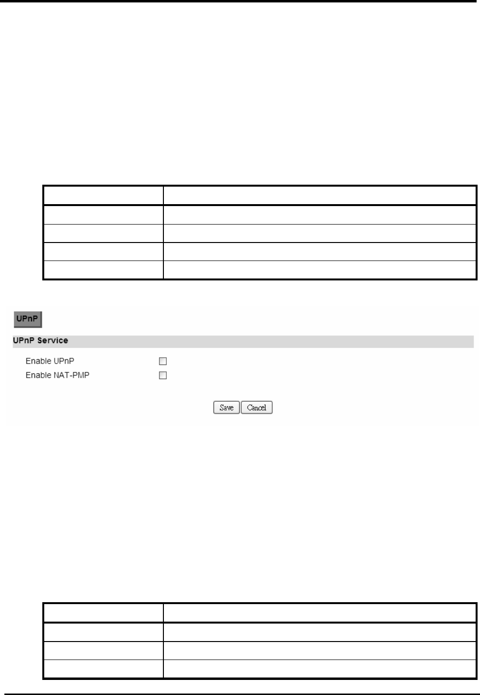
6.4. UPnP
Two methods of simplifying the process of connecting a device to the network are available. UPnP
allows devices to connect seamlessly to networks in the home (data sharing, communications, and
entertainment) and in corporate environments for simplified installation of computer components.
NAT Port Mapping Protocol (NAT-PMP) allows a computer in a private network (behind a NAT router)
to automatically configure the router to allow parties outside the private network to contact itself.
6.4.1. UPnP Setting
“Advanced>UPnP”
Name Description
Enable UPnP Check the check box to enable UPnP.
Enable NAT-PMP Check the check box to enable NAT-PMP.
Save Commit the changes made and save to CPE device.
Cancel Reset fields to the last saved values.
Figure 37. Advanced>UPnP
6.5. IGMP Proxy
IGMP proxy enables the system to issue IGMP host messages on behalf of hosts that the system
discovered through standard IGMP interfaces. The system acts as a proxy for its hosts.
6.5.1. IGMP Proxy Setting
“Advanced>IGMP Proxy”
Name Description
Enable IGMP Proxy Check the check box to enable IGMP Proxy.
Save Commit the changes made and save to CPE device.
Cancel Reset fields to the last saved values.

WM5347N User Manual
43
Figure 38. Advanced>IGMP Proxy
6.6. Content Filter
“Advanced>Content Filter”
Name Description
URL List
Enable URL Filter Check the check box to enable URL Filter
Blacklist/Whitelist Select Blacklist or Whitelist:
Blacklist : The URL list in “URL Filter Rules” wouldn’t be
allowed to access.
Whitelist : Only allow to access the URL list in “URL
Filter Rules”.
URL Filter Rules
Active Check the box to activate the “URL Filter” rule.
URL Enter the URL.
Add Add a new URL filter rule.
OK Click the “OK” button to exit edit table mode
Save Commit the changes made and save to CPE device.
Cancel Reset fields to the last saved values.

WM5347N User Manual
44
Figure 39. Advanced>Content Filter

WM5347N User Manual
45
7. VPN Setting
The “VPN Settings” window will allow you to set rules for VPN.
7.1. PPTP
The Point-to-Point Tunneling Protocol (PPTP) is a method for implementing virtual private
networks. PPTP does not provide confidentiality or encryption; it relies on the protocol being
tunneled to provide privacy.
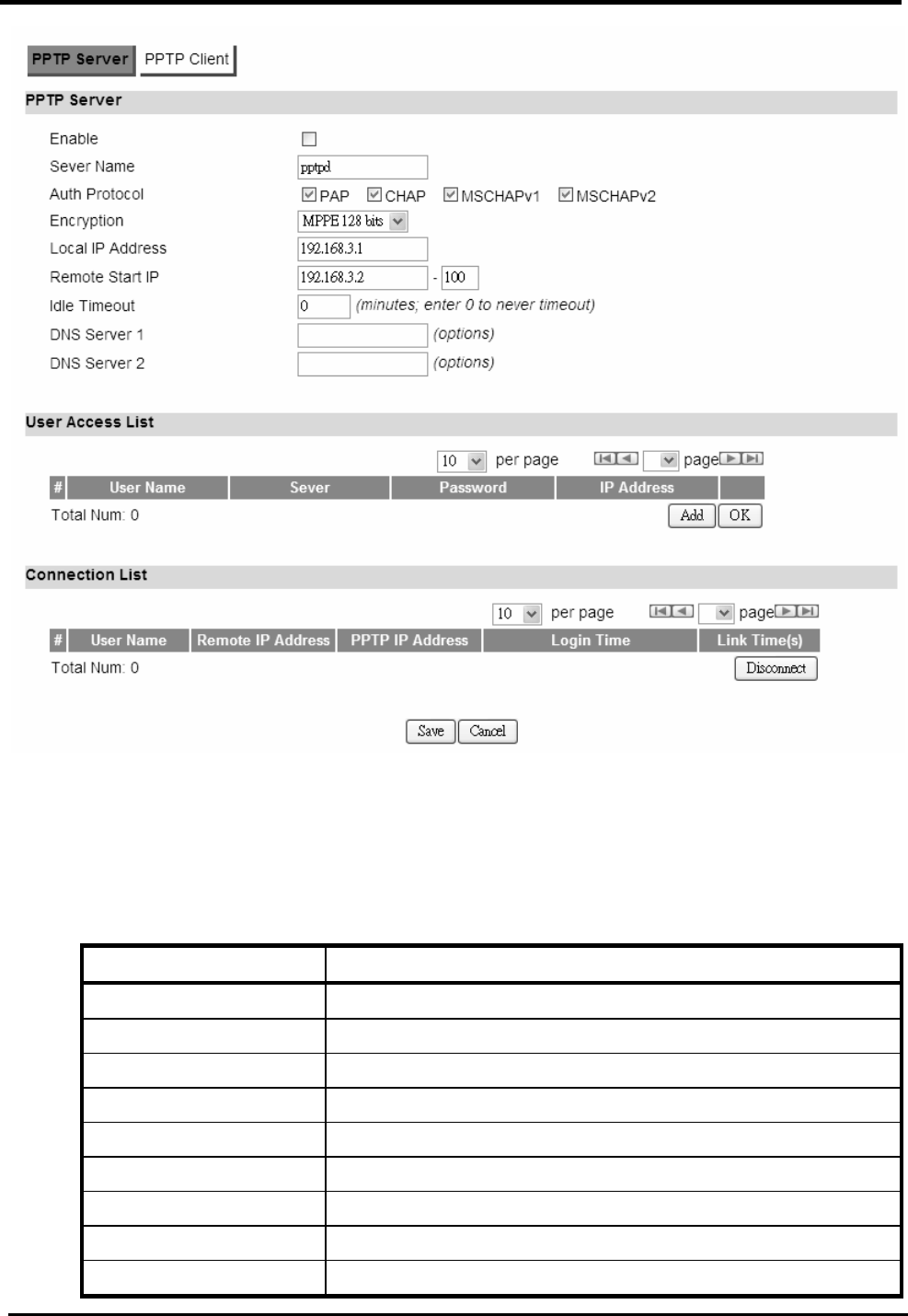
7.1.1. PPTP Server
“VPN>PPTP Server”
Name Description
PPTP Server
Enable Activate PPTP server.
Server Name Offer a server name.
Auth Protocol Require the peer to authenticate itself before allowing
network packets to be sent or received. We support the
following protocol:
PAP: Password Authentication Protocol.
CHAP: Challenge Handshake Authentication Protocol.
MSCHAP: Microsoft Challenge Handshake
Authentication Protocol.
MSCHAPv2: Microsoft Challenge Handshake
Authentication Protocol, Version2.
Encryption Encryption Scheme:
None:
MPPE 40 bits: 40-bit encryption with MPPE.
MPPE 128 bits: 128-bit encryption with MPPE.
Auto: automatically select.
Local IP Address The IP of router.
Remote Start IP As sessions are established, IP addresses are assigned
starting from “Remote Start IP”.
Idle Timeout Disconnect if the link is idle for the assigned seconds.
DNS Server 1 The primary DNS (Domain Name Server) addresses to the

WM5347N User Manual
46
clients.
DNS Server 2 The secondary DNS (Domain Name Server) addresses to
the clients.
User Access List
User Name Username to connect PPTP server via the selected Auth
Protocol.
Server Server protocol type.
Password Password to connect PPTP server via the selected Auth
Protocol.
IP Address IP address of the connected client.
Connection List
User Name The user name of the connection.
Remote IP Address The peer address of the connection.
PPTP IP Address The assigned IP address of PPTP.
Login Time The time of the connection created.
Link Time(s) Timer from the connected time.
Save Commit the changes made and save to CPE device.
Cancel Reset fields to the last saved values.
WM5347N User Manual
47
Figure 40. VPN>PPTP Server
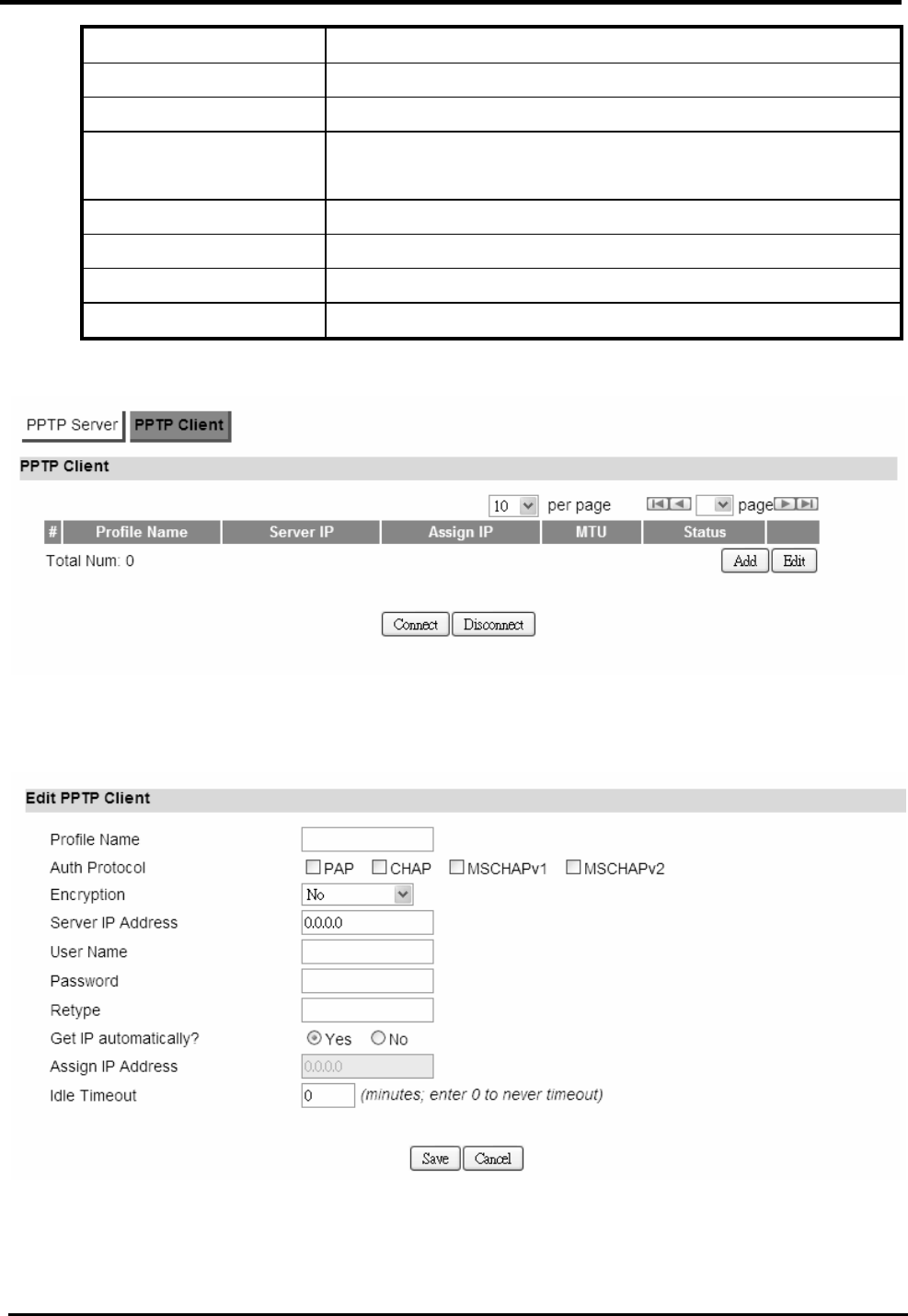
7.1.2. PPTP Client
“VPN>PPTP Client”
Name Description
PPTP Client
Add Add a new connection setting.
Edit Edit the existed connection setting.
Edit PPTP Client
Profile Name The name of this connection setting.
Auth Protocol The authentication protocol of the peer required.
Encryption Encryption Scheme.
Server IP Address The IP address of PPTP server.
User Name The username to connect PPTP server via the selected
WM5347N User Manual
48
Auth Protocol.
Password The password of the corresponding username.
Retype Type the “Password” again.
Get IP automatically? Obtain the dynamic IP address, assigned by the PPTP
server.
Assign IP Address Assign the static IP address for this connection setting.
Idle Timeout Disconnect if the link is idle for the assigned seconds.
Save Commit the changes made and save to CPE device.
Cancel Reset fields to the last saved values.
Figure 41. VPN>PPTP Client
Figure 42. VPN>PPTP Client>Add

WM5347N User Manual
49
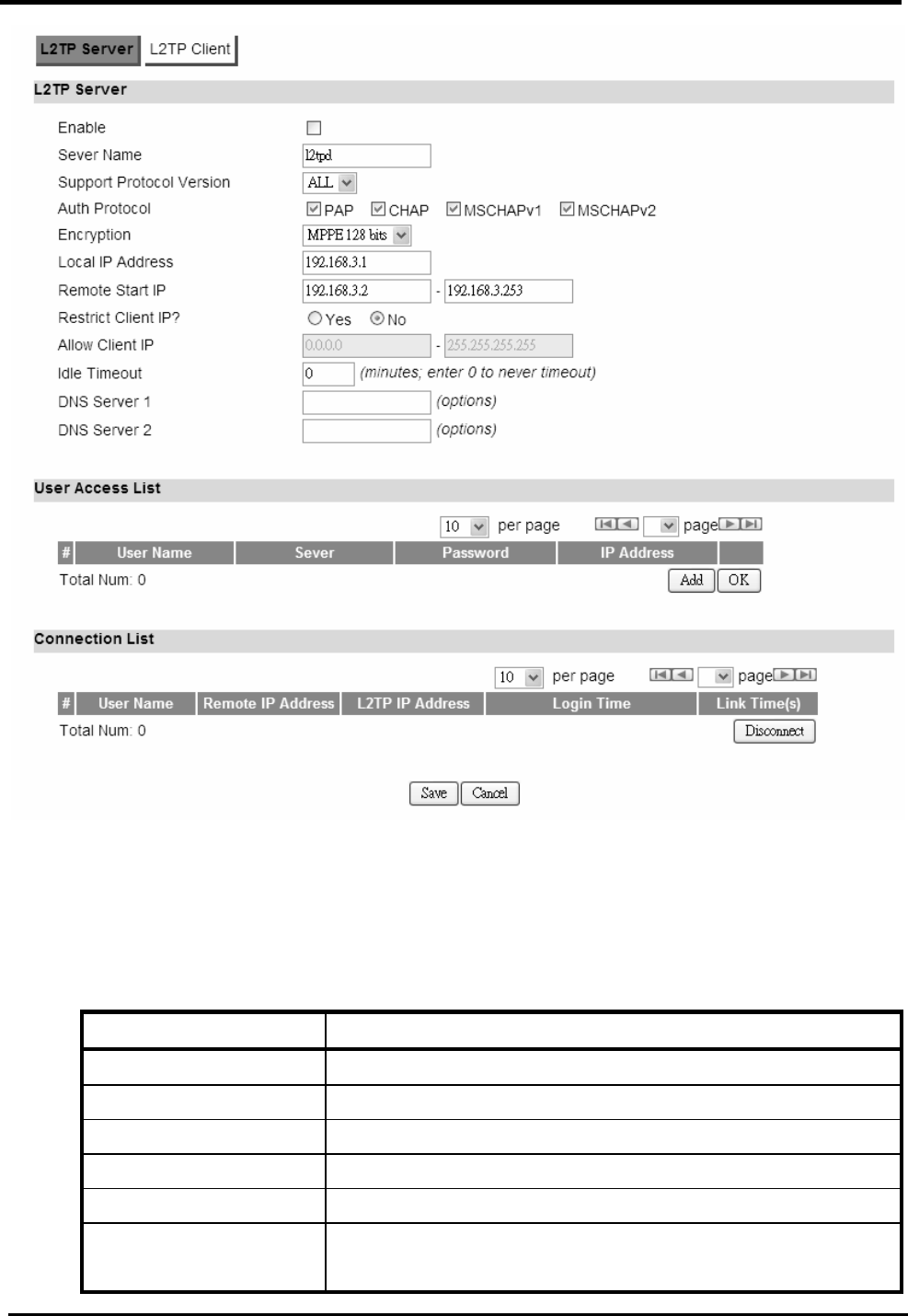
7.2. L2TP
In computer networking, Layer 2 Tunneling Protocol (L2TP) is a tunneling protocol used to support
Virtual Private Networks (VPNs). It dies not provide any encryption or confidentiality by itself; It relies
on an encryption protocol that it passes within the tunnel to provide privacy. The entire L2TP packet,
including payload and L2TP header, is sent within a UDP datagram. It is common to carry
Point-to-Point Protocol (PPP) sessions within an L2TP tunnel. L2TP does not provide confidentiality
or strong authentication by itself. IPsec is often used to secure L2TP packets by providing
confidentiality, authentication and integrity.
http://en.wikipedia.org/wiki/L2TP#cite_note-0
7.2.1. L2TP Server
“VPN>L2TP Server”
Name Description
L2TP Server
Enable Check the box to activate L2TP server.
Server Name Enter a server name.
Auth Protocol Require the peer to authenticate itself before allowing
network packets to be sent or received. The following
protocol are supported:
PAP: Password Authentication Protocol.
CHAP: Challenge Handshake Authentication Protocol.
MSCHAP: Microsoft Challenge Handshake
Authentication Protocol.
MSCHAPv2: Microsoft Challenge Handshake
Authentication Protocol, Version2.
Encryption Encryption Scheme:
No
MPPE 40 bits: 40-bit encryption with MPPE.
MPPE 128 bits: 128-bit encryption with MPPE.
Auto: automatically select.
Local IP Address The IP of router.
Remote Start IP As sessions are established, IP addresses are assigned
starting from “Remote Start IP”.
Restrict Client IP? To restrict IP address range for the client.
Allow Client IP The IP address range for the client.
Idle Timeout Disconnect if the link is idle for the given number of

WM5347N User Manual
50
seconds.
DNS Server 1 The primary DNS (Domain Name Server) addresses to the
clients.
DNS Server 2 The secondary DNS (Domain Name Server) addresses to
the clients.
User Access List
User Name Username to connect L2TP server via the selected Auth
Protocol.
Server Server protocol type.
Password Password to connect L2TP server via the selected Auth
Protocol.
IP Address IP address of the connected client.
Connection List
User Name The user name of the connection.
Remote IP Address The peer address of the connection.
L2TP IP Address The assigned IP address of L2TP.
Login Time The time of the connection created.
Link Time(s) Elapsed time connected.
Save Commit the changes made and save to CPE device.
Cancel Reset fields to the last saved values.
WM5347N User Manual
51
Figure 43. VPN>L2TP Server
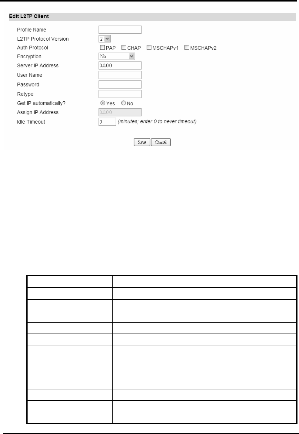
7.2.2. L2TP Client
“VPN>L2TP Client”
Name Description
L2TP Client
Add Add a new connection setting.
Edit Edit the existed connection setting.
Edit L2TP Client
Profile Name The name of this connection setting.
Auth Protocol The authentication protocol of the peer required. Select
which Authentication protocol to use.

WM5347N User Manual
52
PAP
CHAP
MSCHAPv1
MSCHAPv2
Encryption Encryption Scheme:
No
MPPE 40 bits: 40-bit encryption with MPPE.
MPPE 128 bits: 128-bit encryption with MPPE.
Auto: automatically select.
Server IP Address The IP address of L2TP server.
User Name The username to connect L2TP server via the selected
Auth Protocol.
Password The password of the corresponding username.
Retype Type the “Password” again.
Get IP automatically? Obtain the dynamic IP address, assigned by the L2TP
server.
Assign IP Address Assign the static IP address for this connection setting.
Idle Timeout Disconnect if the link is idle for the assigned seconds.
Save Commit the changes made and save to CPE device.
Cancel Reset fields to the last saved values.
Figure 44. VPN>L2TP Client
WM5347N User Manual
53
Figure 45. VPN>L2TP Client>Add
7.3. IPsec
Internet Protocol Security (IPsec) is an end-to-end security solution and operated at the IP Layer.
It provides secure communication between pairs of hosts, pairs of security gateways or between
security gateways and a host. It’s based on a suite of protocols for securing IP traffic by
authenticating and encrypting each IP packet of the data stream.
7.3.1. Connection
“VPN>IPsec>Connection”
Name Description
Configuration
Add Click the “Add” button to add an IPsec connection rule.
Property
Enable Enable IPsec connection.
Connection Name The name of the connection.
Connection Type Select the connection type:
Initiator
On Demand
Responder
Gateway Information
Local Endpoint Interface
The interface of the CPE public-network interface.
Local Endpoint IP The IP address or Domain Name of the CPE

WM5347N User Manual
54
Address public-network interface.
Remote End point IP
Address
The IP address or Domain Name of the remote peer.
Authentication Method
Pre-Shared Key The pre-shared key that two security gateways use to
authenticate.
Local ID Type States how the CPE should be identified for
authentication.
IP: The CPE is identified by the assigned IP for
authentication. The default value is 0.0.0.0.
Content The IP Address.
Remote ID Type States how the remote peer should be identified for
authentication.
IP: The remote peer is identified by the assigned IP
for authentication. The default value is 0.0.0.0; this
means the CPE will accept any IP.
Connect The IP Address.
IKE Phase 1
Proposal Add Press the Add button to enter an Encryption and
Authentication algorithm. Click the trash to remove the
selected algorithm.
Encryption Algorithm:
DES
3DES
AES128
AES192
AES256
Authentication Algorithm:
MD5
SHA-1
Proposal OK Click the OK button to exit the table edit mode.
Key Group The DH group used to negotiate the IKE/ISAKMP SA.
SA Life Time The period that the keying channel of a connection
(IKE/ISAKMP SA) should last before being
renegotiated.
Dead Peer Detection Enable or disable the Dead Peer Detection protocol.

WM5347N User Manual
55
(DPD) (RFC 3706)
DPD Interval The time interval when R_U_THERE messages are
sent to the peer.
DPD Idle Try The retry counter for DPD. The timeout interval is “DPD
interval” multiplied by “DPD Idle Try”. After the timeout
interval all connections to the peer are deleted if they
are inactive.
Local Network The private subnet behind the CPE.
Address Type Single address: The private subnet consisting of
one IP address.
Subnet address: The private subnet consisting
within the subnet IP addresses.
Start IP Address The only IP address allowed in the subnet.
Subnet Mask The net mask of the subnet. (Subnet address)
Local Port Restrict the traffic selector to a single protocol and/or
port.
Any: No restriction
ICMP: Restrict the traffic selector to ICMP protocol.
TCP: Restrict the traffic selector to TCP protocol. If
the port number is 0, all TCP port numbers are
accepted.
UDP: Restrict the traffic selector to UDP protocol. If
the port number is 0, all UDP port numbers are
accepted.
Remote Network The private subnet behind the remote peer.
Address Type Single address: The private subnet consisting of
one IP address.
Subnet address: The private subnet consisting of
the subnet IP addresses.
Start IP Address The only IP address allowed in the subnet.
Subnet Mask The net mask of the subnet (Subnet address).
Remote Port Restrict the traffic selector to a single protocol and/or
port.
Any: No restriction
ICMP: Restrict the traffic selector to ICMP protocol.
TCP: Restrict the traffic selector to TCP protocol. If
the port number is 0, all TCP port numbers are
accepted.

WM5347N User Manual
56
UDP: Restrict the traffic selector to UDP protocol. If
the port number is 0, all UDP port numbers are
accepted.
IPSec Proposal
Encapsulation Mode The type of the connection:
Tunnel: Signifying a host-to-host, host-to-subnet, or
subnet-to-subnet tunnel.
Transport: Signifying host-to-host transport mode.
Activate Protocol Whether authentication should be done as part of ESP
encryption and/or separately using the AH protocol.
Encryption Algorithm NULL
AES128
AES192
AES256
DES
3DES
Authentication Algorithm
MD5
SHA-1
SA Life Time The time interval a particular instance of a connection
(a set of encryption/authentication keys for user
packets) should last, from successful negotiation to
expiry.
Perfect Forward
Secrecy (PFS)
Whether Perfect Forward Secrecy of keys is desired on
the connection’s keying channel.
Save Commit the changes made and save to CPE device
Cancel Reset fields to the last saved values
Figure 46. VPN>IPsec>Connection Overview
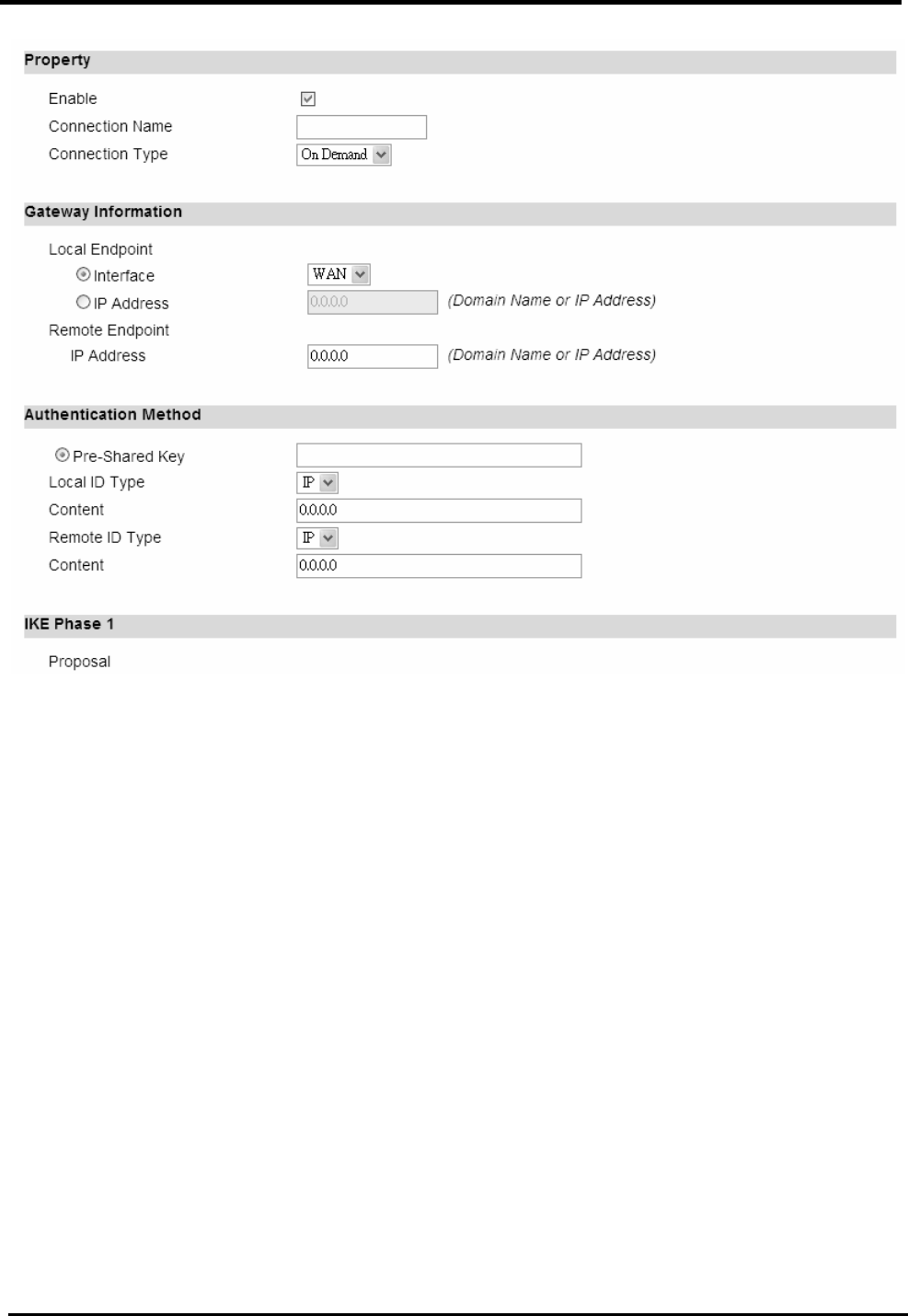
WM5347N User Manual
57
Figure 47. VPN>IPsec>Connection>Add
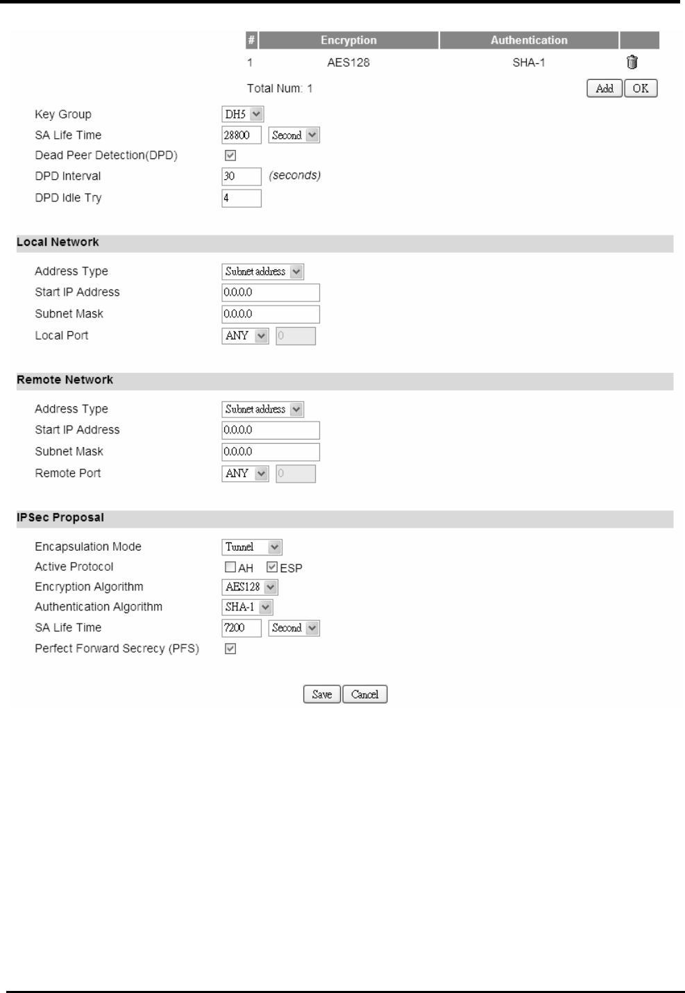
WM5347N User Manual
58
Figure 48. VPN>IPsec>Connection>Add (Continued)
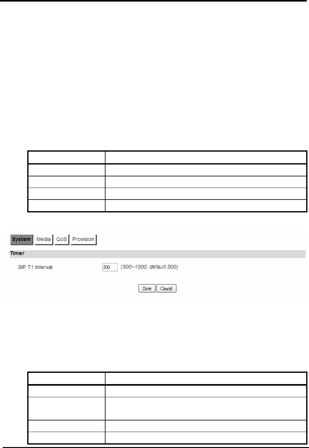
WM5347N User Manual
59
8. VoIP Phone
8.1. General
Voice over Internet Protocol (VoIP) is a method of delivery of voice communication over the
internet or packet-switched network. Internet telephony refers to communications services ― voice,
facsimile, and/or voice-messaging applications ― that are transported via the Internet, rather than
the public switched telephone network (PSTN).
8.1.1. System
“VoIP Phone>General>System”
Name Description
Timer
SIP T1 Interval A T1 timer defined in SIP protocol.
Save Commit the changes made and save to CPE device.
Cancel Reset fields to the last saved values.
Figure 49. VoIP Phone>General>System
8.1.2. Media
“VoIP Phone>General>Media”
Name Description
Port
Media Port Start RTP local start port number, (start~end) defined the RTP
listen port range.
Media Port End RTP local end port number.
Dynamic Payload

WM5347N User Manual
60
Type Setting
G.726 16K Default is 96
G.726 24K Default is 97
G.726 32K Default is 98
G.726 40K Default is 99
iLBC Default is 104
Telephone-event Default is 101
Codec
Packetization Time
Settings
G.711
Default is 20
G.723
Default is 30
G.726
Default is 20
G.729
Default is 20
iLBC
Default is 30
Advanced
Voice Jitter Buffer
Type
There are “Dynamic” and “Static” type which can be
selected in the voice jitter buffer type.
Voice Jitter Buffer
Length
Voice Jitter Buffer Length.
Packet Loss
Concealment
Enable to mask the effects of packet loss.
DVCC Enable
Enable DVCC.
T.38 Static Jitter
Length
T.38 Static Jitter Length.
Save Commit the changes made and save to CPE device.
Cancel Reset fields to the last saved values.
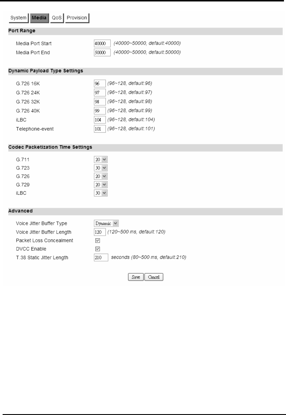
WM5347N User Manual
61
Figure 50. VoIP Phone>General>Media
8.1.3. QoS
QoS is the differentiation between types of traffic and types of services so that the different types of
service and traffic can be treated different service. This way, one type can be favored over another.
In VoIP, quality simply means being able to listen and speak in a clear and continuous voice, without
unwanted noise. DiffServ is a QoS protocol for managing bandwidth application for internet media
connections.
“VoIP Phone>General>QoS”
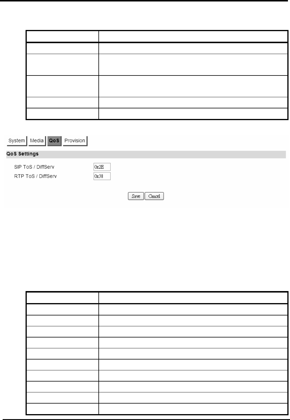
WM5347N User Manual
62
Name Description
QoS Settings
SIP ToS/DiffServ The SIP ToS rule will tag each SIP outgoing packet which
will prioritize SIP traffic.
RTP ToS/DiffServ The RTP ToS rule will tag each RTP outgoing packet
which will prioritize RTP traffic.
Save Commit the changes made and save to CPE device.
Cancel Reset fields to the last saved values.
Figure 51. VoIP Phone>General>QoS
8.1.4. Provision
Provision is a functionality to update the configuration by the FTP protocol.
“VoIP Phone>General>Provision”
Name Description
Provision Settings
Enable Enable or Disable.
FTP Server FTP server address.
File Path File path and file name.
Logging User Name Login username.
Logging Password Login password.
Connection Timeout Connection timeout.
Retry Count Retry count.
Save Commit the changes made and save to CPE device.
Cancel Reset fields to the last saved values.
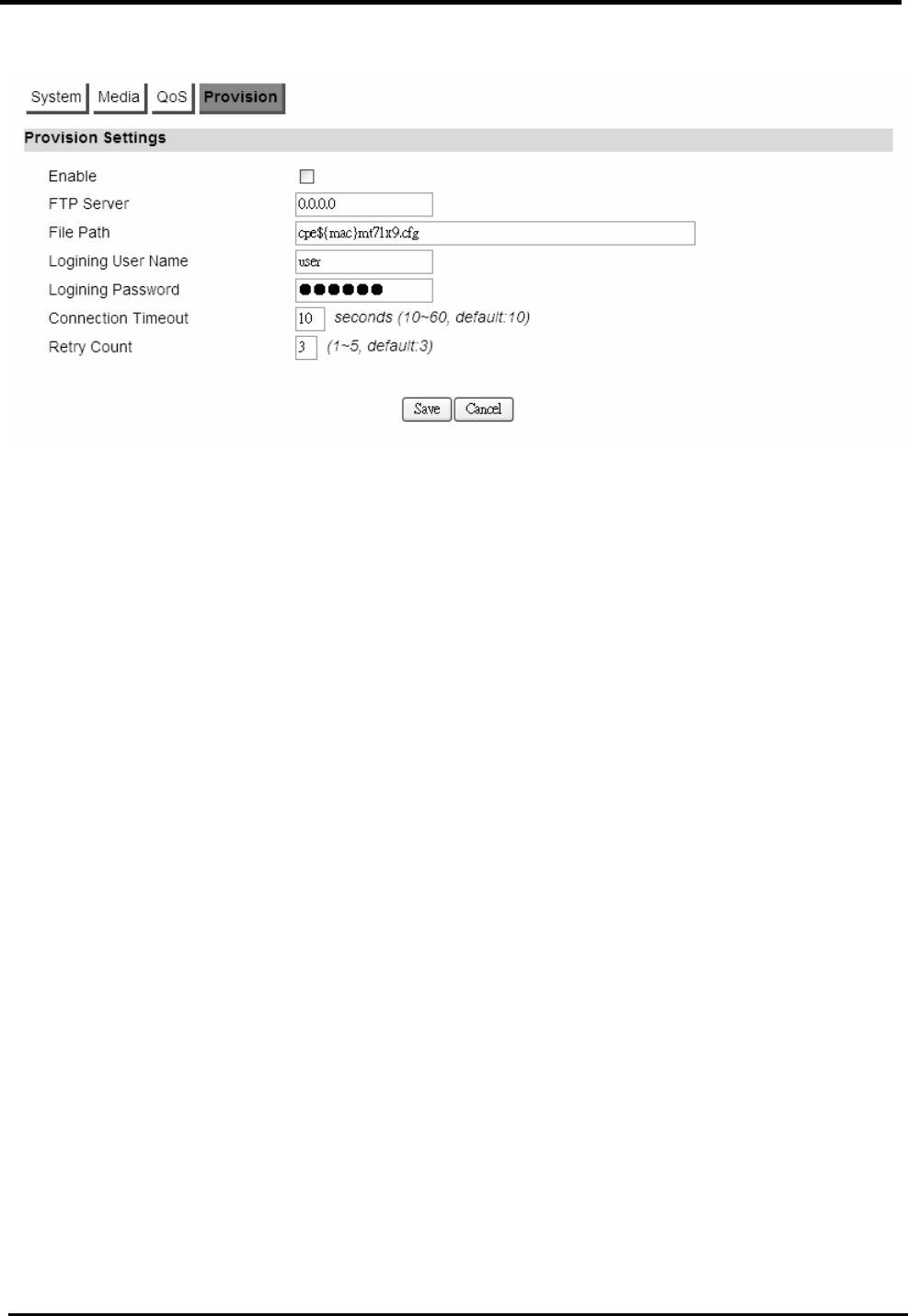
WM5347N User Manual
63
Figure 52. VoIP Phone>General>Provision
8.2. Account
NOTE: The following figures will apply for Account 1, Account 2, Account 3 and Account 4.
8.2.1. Status
Show server information, account register status and call history.
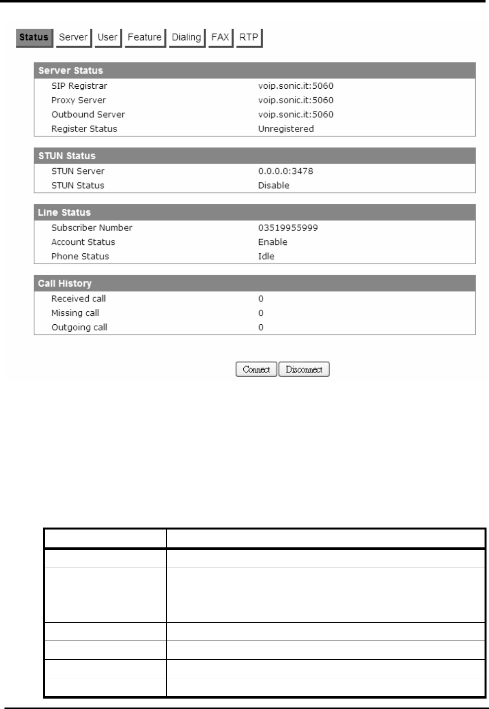
WM5347N User Manual
64
Figure 53. VoIP Phone>Account 1-4>Status
8.2.2. Server
Configure the server information for Account 1 and Account 2.
“VoIP Phone>Account>Server”
Name Description
Register Server
Register Server A SIP registrar is a server in a Session Initiation Protocol
(SIP) network that accepts and processes SIP REGISTER
requests. Format is “x.x.x.x”.
Port Number A registrar server port number, default is 5060.
Register Period Time
Register refresh time.
Proxy Server
Proxy Server A SIP proxy is a server in a Session Initiation Protocol
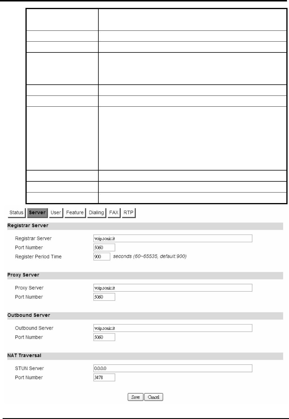
WM5347N User Manual
65
(SIP) network that route sip message to a right place.
Format is “x.x.x.x”.
Port Number A proxy server port number, default is 5060.
Outbound Server
Outbound Server The outbound proxy is placed alongside the firewall and is
the only way to let SIP traffic pass from the internal
network to the internet. Format is “x.x.x.x”.
Port Number An outbound server port number, default is 5060.
NAT Traversal
STUN Server Enter the IP address of the STUN server, it will send and
receive STUN requests and responses. Simple Traversal
of User Datagram Protocol (STUN) through NATs is a
standards-based IP protocol used as one of the methods
of NAT traversal in applications of real-time voice, video,
messaging, and other interactive IP communications.
Port Number A STUN server port number, default is 3478.
Save Commit the changes made and save to CPE device.
Cancel Reset fields to the last saved values.
Figure 54. VoIP Phone>Account 1-2>Server

WM5347N User Manual
66
8.2.3. User
“VoIP Phone>Account>User”
Name Description
SIP Account
Enable Enable or disable the SIP account.
Subscriber Number Enter the subscriber number for Line. The number is a
unique series of digits of VoIP subscriber. It’s used to
interconnect with SIP server, for outgoing or incoming
calls.
Display Name The display name of the VoIP subscriber, shown when it
makes outgoing calls. Maximum name size is 64
characters.
Authentication Name
A unique string of VoIP subscriber. It’s used to
authenticate subscriber to get authorization to perform call
setup privilege.
Password Enter the password.
Codec Settings See Table 3 for Codec options.
1
st
Codec Subscriber prefers codec and it has 1
st
priority in codec
negotiation.
2
nd
Codec Subscriber prefers codec and it has 2
nd
priority in codec
negotiation.
3
rd
Codec Subscriber prefers codec and it has 3
rd
priority in codec
negotiation.
4
th
Codec Subscriber prefers codec and it has 4
th
priority in codec
negotiation.
5
th
Codec Subscriber prefers codec and it has 5
th
priority in codec
negotiation.
6
th
Codec Subscriber prefers codec and it has 6
th
priority in codec
negotiation.
7
th
Codec Subscriber prefers codec and it has 7
th
priority in codec
negotiation.
8
th
Codec Subscriber prefers codec and it has 8
th
priority in codec
negotiation.
9
th
Codec Subscriber prefers codec and it has 9
th
priority in codec
negotiation.

WM5347N User Manual
67
G.723.1 Rates 5.3 kbps
6.3 kbps
iLBC Rates 20 ms
30 ms
Media
SIP User Agent
Name
Indicates a specific name for SIP user in SIP message.
SIP Port SIP local port, it responsible for the sip packet send and
receive.
Session Timer Flag
Enable
Enable session timer.
Session Timer The SIP session timer periodical refreshes time.
Min Session Timer The minimal SIP session timer periodical refreshes time.
Timeout for Ring
back
Ring back timeout. When ring back timeout judge the
action behavior, such as hang-up or busy forward and so
on.
Save Commit the changes made and save to CPE device.
Cancel Reset fields to the last saved values.
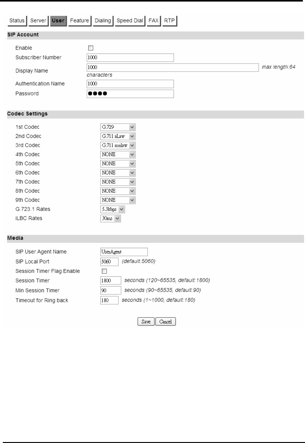
WM5347N User Manual
68
Figure 55. VoIP Phone>Account 1-2>User

WM5347N User Manual
69
Codec Settings Options
1. G.729
2. G.723.1
3. G.726 16K
4. G.726 24K
5. G.726 32K
6. G.726 40K
7. G.711 aLaw
8. G.711 mulaw
9. iLBC
Table 3: Codec Setting Options
8.2.4. Feature
“VoIP Phone>Account>Feature”
Name Description
Feature Settings
Auto Decline Anonymous When VoIP subscriber receives an incoming call with
privacy, with display name as “anonymous”. VoIP
subscriber can REJECT it when the setting “Auto
Decline Anonymous” is enabled. If it’s not enabled it
will treat it as a normal incoming call and allow the
phone device to ring.
Do Not Disturb (DND) When it is enabled, it will reject all incoming call
Hide User ID As “Calling Line Identification Restriction (CLIR)”,
VoIP subscriber can enable this function to hide its
identifier to others, when VoIP subscriber makes an
outgoing call.
MWI Message waiting indication. The LED on select
telephones will light-up to notify the user that they
have voicemail.
Call Forwarding Setting
All Call Forwarding (All
CF)
Enable/Disable, call forward feature
Unconditional CF Enable/Disable unconditional call forward feature.

WM5347N User Manual
70
Unconditional CF Target Unconditional call forwarding target number.
Busy CF Enable/Disable, busy forward feature.
Busy CF Target Busy forward target number.
No Answer CF Enable/Disable, No Answer call forward feature.
No Answer CF Target No answer call forward target number.
Call Waiting Setting
Call Waiting Enable/Disable Call waiting feature.
Hotline setting
Hotline Enable Hotline.
Hotline Target The number of hotline target.
Hotline Period Time Period time of hotline.
Save Commit the changes made and save to CPE device.
Cancel Reset fields to the last saved values.
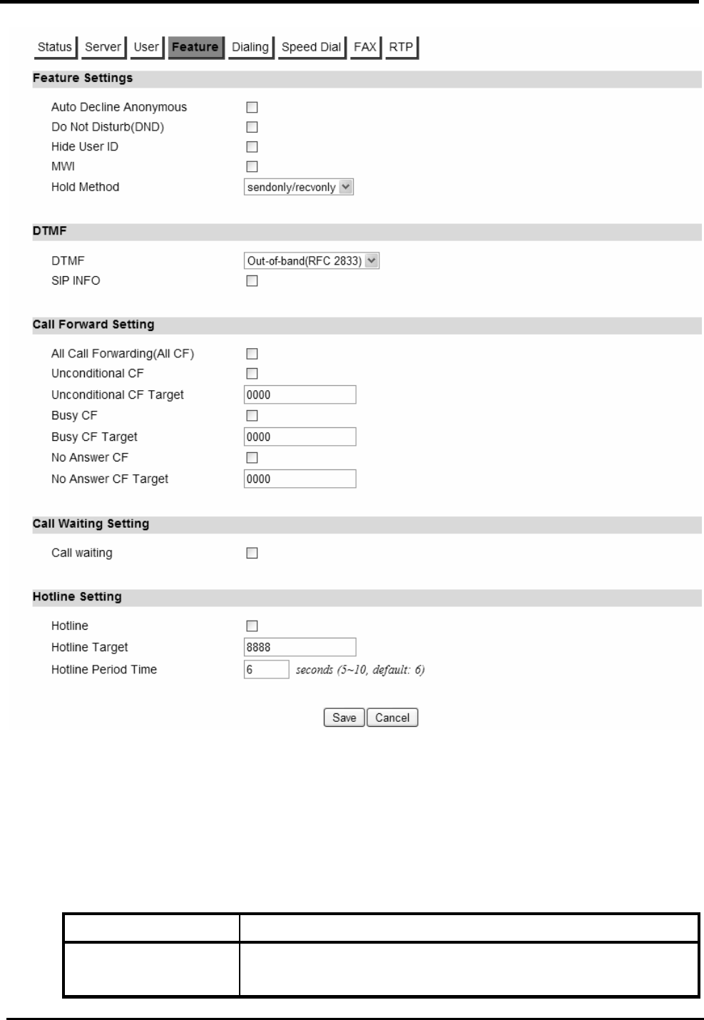
WM5347N User Manual
71
Figure 56. VoIP Phone>Account 1-2>Feature
8.2.5. Dialing
“VoIP Phone>Account>Dialing”
Name Description
General Dialing
Settings
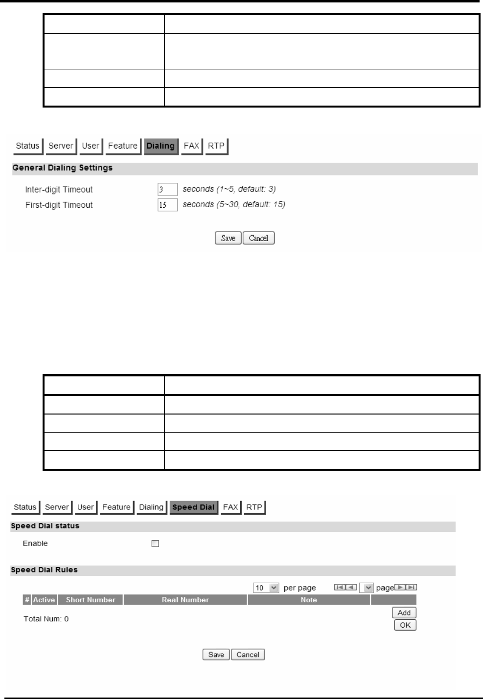
WM5347N User Manual
72
Inter-digit Timeout The time period between each digit.
First-digit Timeout The maximum time allowed between off-hook and entering
the first digit.
Save Commit the changes made and save to CPE device.
Cancel Reset fields to the last saved values.
Figure 57. VoIP Phone>Account 1-2>Dialing
8.2.6. Speed Dial
“VoIP Phone>Account>FAX”
Name Description
Speed Dial status
Enable Enable Speed dial.
Speed Dial Rules
User make real number simplify to short number.

WM5347N User Manual
73
Figure 58. VoIP Phone>Account 1-2>Speed Dial
8.2.7. FAX
“VoIP Phone>Account>FAX”
Name Description
FAX Settings
Options NONE
G.711A Pass Through
G.711U Pass Through
T.38 FAX Relay
T.38 FAX Only
Save Commit the changes made and save to CPE device.
Cancel Reset fields to the last saved values.
Figure 59. VoIP Phone>Account 1-2>FAX
8.2.8. RTP
“VoIP Phone>Account>RTP”
Name Description
RTP Setting
RTP Detection
Enable
Enable RTP Detection.
RTP Timeout The RTP timeout is used to judge the call is it still alive and
do the right action. The range is from 10-300, 40 seconds
is the default value.

WM5347N User Manual
74
RTP Packet Loss
Percentage
You can specify the allowable RTP Packet Loss
percentage and if it reaches the %, and do the right action.
Save Commit the changes made and save to CPE device.
Cancel Reset fields to the last saved values.
Figure 60. VoIP Phone>Account 1-2>RTP
8.3. Line
NOTE: The following figures will apply for Line 1 and Line 2. The Line and Account is one-to-one
mapping, that is, the Line 1 is mapping to Account 1, and Line 2 is mapping to Account 2.
8.3.1. Phone
“VoIP Phone>Line>Phone”
Name Description
Phone
Hook Flash Detect
Upper Bound
This parameter defines the upper bound of the quick
on/off-hook cycle.
Hook Flash Detect
Lower Bound
This parameter defines the lower bound of the quick
on/off-hook cycle.
Voice Tx Level The voice gain level that is heard by a telephone user.
Voice Rx Level The voice gain level that is received by the device.
Ring Impedance The impedance between tip and ring on the telephone line.
Caller ID
Caller ID Type This will allow you to enable and select the Called ID type
for your area. You also have the choice to disable caller ID.
Disable
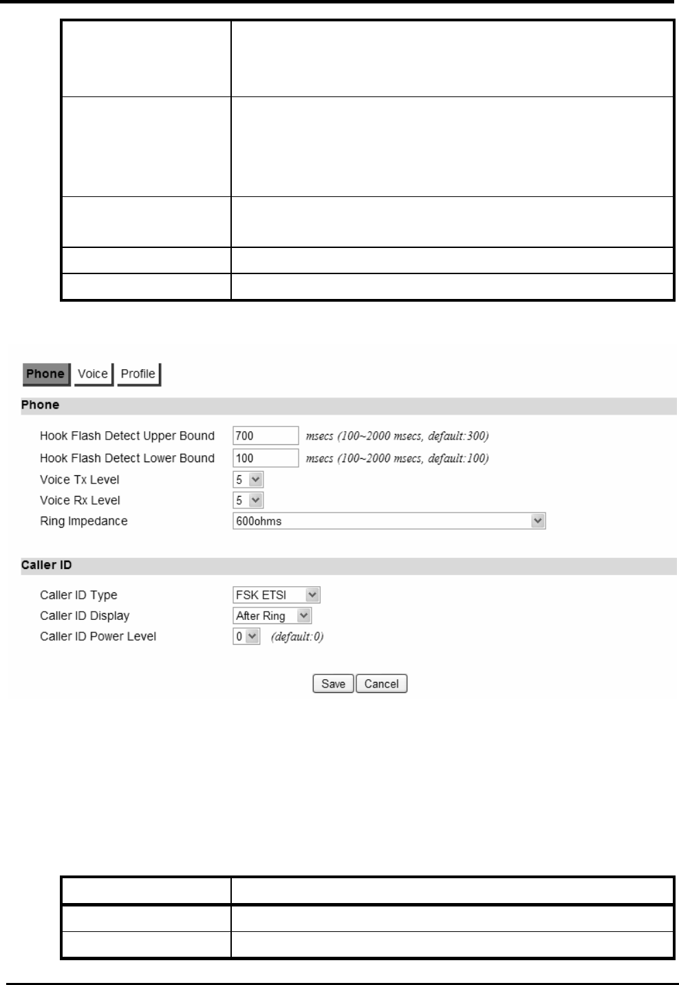
WM5347N User Manual
75
FSK Bellcore
FSK ETSI
Japan CLIP
Caller ID Display This parameter configures when Caller ID will be
displayed.
Before Ring
After Ring
Caller ID Power
Level
The transmitting power level of caller ID to the telephone.
Save Commit the changes made and save to CPE device.
Cancel Reset fields to the last saved values.
Figure 61. VoIP Phone>Line 1-2>Phone
8.3.2. Voice
“VoIP Phone>Line>Voice”
Name Description
VAD
Voice Active You can enable and select which voice activity detection to
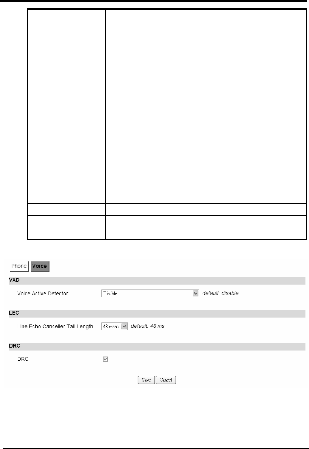
WM5347N User Manual
76
Detector use. It can facilitate speech processing, and can also be
used to deactivate some processes during non-speech
segments: it can avoid unnecessary coding/transmission
of silence packets in VoIP, saving on computation and on
network bandwidth. There are 4 choices to select from.
Disable
Silence Suppression ― NO CNG
Silence Suppression ― Only G.711 Annex II Type
Silence Suppression ― Codec Specific CN (G.729 and
G.732)
LEC
Line Echo Canceller
Tail Length
There are processing delays in IP networks that could
cause an echo. This function is used to decrease the echo
effect.
We provide disable, 16ms, 32ms and 48ms echo tail length
setting.
DRC
DRC Enable/Disable DRC.
Save Commit the changes made and save to CPE device.
Cancel Reset fields to the last saved values.
Figure 62. VoIP Phone>Line 1-2>Voice
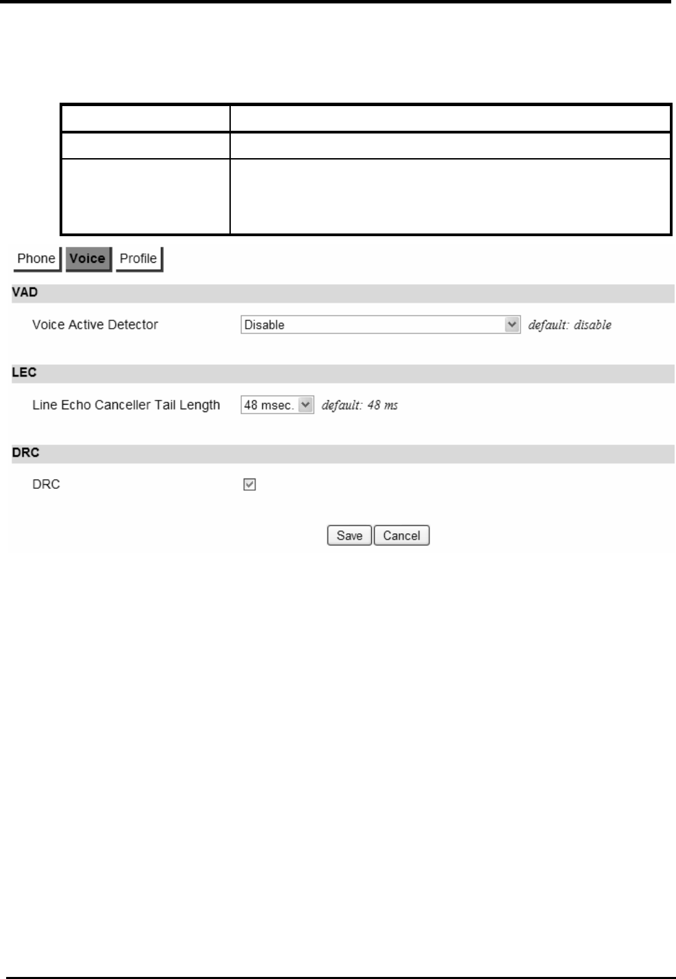
WM5347N User Manual
77
8.3.3. Profile
“VoIP Phone>Line>Profile”
Name Description
Country Profile
For different countries, the tones may be different. This
parameter is used to set the country name to change the
tones.
Figure 63. VoIP Phone>Line 1-2>Profile

WM5347N User Manual
78
9. WiMAX
This technology is based on the IEEE 802.16 standard, enabling the delivery of last mile wireless
broadband access.
9.1. Profile
In the profile tab, the user can set WiMAX standard settings, which include how to establish a
connection, frequency information and how to authenticate.
9.1.1. Connect Settings
“WiMAX>Profile>Connect Settings”
Name Description
Auto Reconnect Indicate the interval in second to “auto reconnect”. 0
means disabled.
Auto connect Mode Connecting base on CINR or RSSI to connect the best
signal.
NDS Mode Enable NDS mode.
NDS Network
Parameters File
Upload NDS Network Parameters File.
Enable Handover Enable Handover.
Enable Idle Mode Enable Idle mode.
Idle Mode Interval The time interval of idle mode.
CINR & RSSI
Refresh Interval
Refresh time interval of CINR & RSSI.
LDRP Time LDRP (Low Data Rate Protection). When it’s enabled, if
the uplink/downlink data rate is smaller than the LDRP
time, the CPE will send disconnect command to BS.
LDRP TX/RX Rate LDRP uplink/downlink data rate.
Search Click on the search button to search for available BSIDs.
Connect Mode Select a connect mode
Auto Connect Mode: It will connect to one of the BSIDs
in the list, indiscriminately.
Network Search Mode: User needs to select one of the
BSIDs from the list, it will use that BSID to connect to
WiMAX after device is reboot.
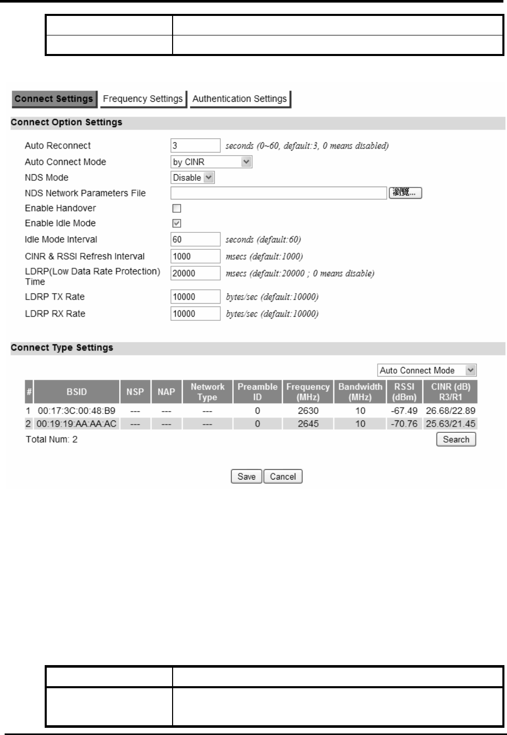
WM5347N User Manual
79
Save Commit the changes made and save to CPE device.
Cancel Reset fields to the last saved values.
Figure 64. WiMAX>Profile>Connect Settings
9.1.2. Frequency Settings
The frequency list window will display all the configured frequencies and their bandwidth. To set
additional frequencies, click on the “Add” button.
“WiMAX>Profile>Frequency Settings”
Name Description
Setting Type There are two display types you can select.
You can choose to display the data by List. If you select
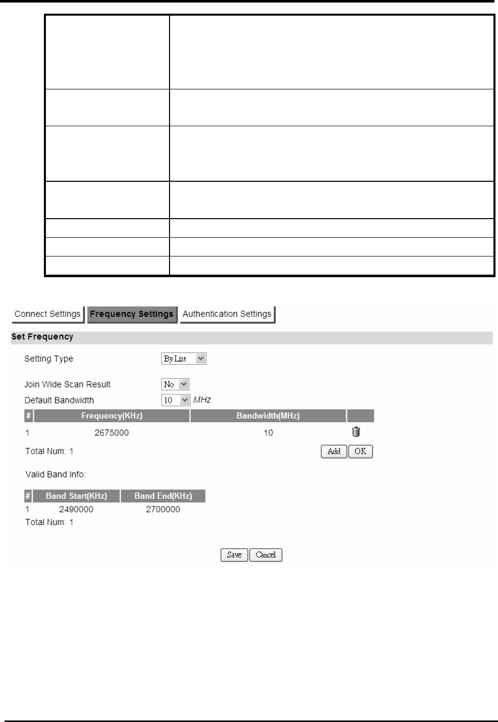
WM5347N User Manual
80
“By List” you also have the option to add more
frequencies.
“By Range” will display the frequency by range and the
incremental value. See Figure “Frequency By Range”.
Joint Wide Scan
Result
Yes means to append wide scan result to the frequency
setting. Only valid when setting type is “By List”.
Valid Band Info Valid band information. If the frequencies aren’t located
using the valid band range, the frequency setting will be
rejected.
Add The “Add” button will aloe you to enter more frequency
lists.
OK Click the “OK” button to exit the table edit mode.
Save Commit the changes made and save to CPE device.
Cancel Reset fields to the last saved values.
Figure 65. WiMAX>Profile>Frequency Settings (By List)

WM5347N User Manual
81
Figure 66. WiMAX>Profile>Frequency Settings (By Range)
9.1.3. Authentication Settings
“WiMAX>Profile>Authentication Settings”
Name Description
Authentication
Authentication Mode
The method used in authentication.
Date Encryption
AES-CCM
Enable the MS’s capability of encrypting/decrypting the
traffic by AES-CCM.
Data Encryption
AES-CBC
Enable the MS’s capability of encrypting/decrypting the
traffic by AES-CBC.
Key Encryption
AES-key wrap
Enable the MS’s capability of decrypting TEK by AES-Key
wrap.
Key Encryption
AES-ECB
Enable the MS’s capability of decrypting TEK by
AES-ECB.
EAP Supplicant
EAP Mode The EAP method used in authentication.
Anonymous ID The identity encoded in EAP Identity Response message.
Server Root CA
Certificate
The root CA’s X.509 certificate.
MTK-Authorized
Device Certificate
The MS’s X.509 certificate.

WM5347N User Manual
82
Device Private Key The MS’s private key file corresponding to the public key
encoded in X.509 certificate.
Device Private Key
Password
The key used to decrypt the MS’s private key file.
Inner Mode The EAP-TTLS inner method.
User name The user name used in EAP-TTLS inner method.
Password The password used in EAP-TTLS inner method.
Options
Auto Prepend Auth
Mode
Enable the MS to automatically decorate “{am=i}” in the
EAP Identity Response message. The value of “i” depends
on Authentication Mode field.
Random Outer ID Enable the MS to generate 16-bytes random number as
the user name in the EAP Identity Response message.
Ignore Cert
Verification
MS skips to verify the BS’s certificate received in the
EAP-TLS or EAP-TTLS procedure.
Same EAP outerID
in ReAuth
Use the same EAP outer id when doing re-auth.
MAC address in
EAP-TLS outer ID
Add MAC address in outer id when EAP mode is
EAP-TLS.
Delete existed
Device Certificate file
Delete device certificate file which was uploaded in the
filed “MTK-authorized Device Certificate”
Delete existed
Private Key
Delete device private key which was uploaded in the filed
“Device Private Key”
Save Commit the changes made and save to CPE device
Cancel Reset fields to the last saved values
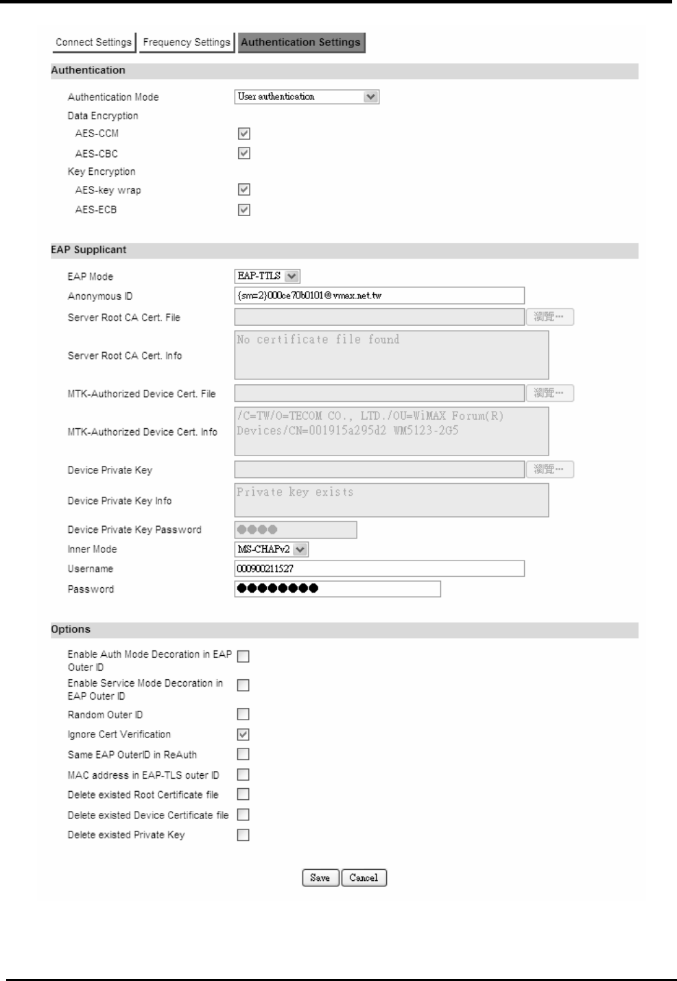
WM5347N User Manual
83
Figure 67. WiMAX>Profile>Authentication Settings

WM5347N User Manual
84
9.2. Connect
“WiMAX>Connect>Connect”
Name Description
Disconnect Click the disconnect button to terminate the connection.
Connect Click the connect button to connect to a BSID.
Connect Mode Select a connect mode.
Auto Connect Mode: It will connect to one of the BSIDs
in the list, indiscriminately.
Network Search Mode: User needs to select one of the
BSIDs from the list, it will use that BSID to connect to
WiMAX after device is reboot.
Search Click the search button to scan the frequency.
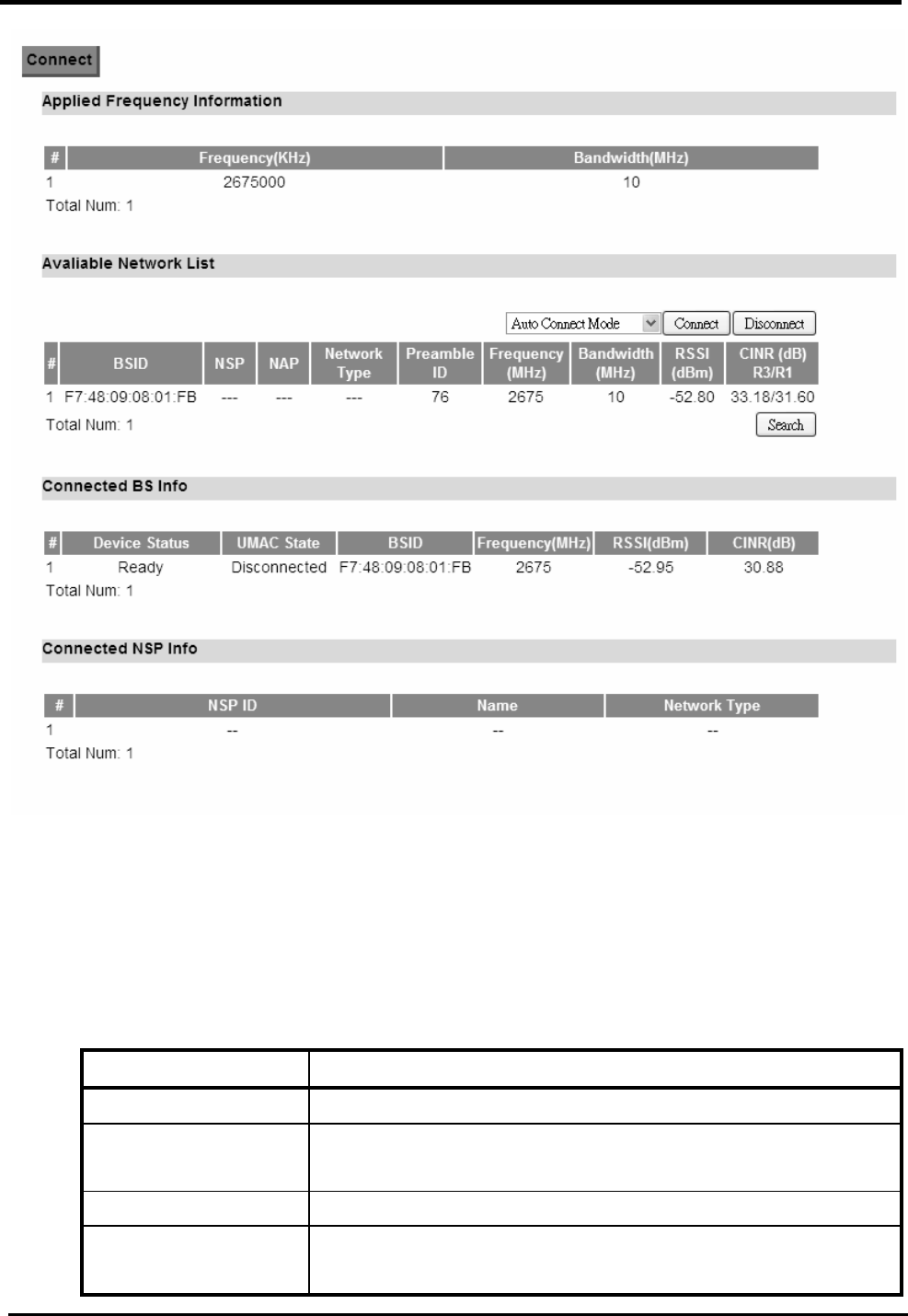
WM5347N User Manual
85
Figure 68. WiMAX>Connect
9.3. Wide Scan
“WiMAX>Wide Scan”
Name Description
Wide Scan Settings
Auto Wide Scan Select “Yes” to do “wide scan” automatically when there
are no available BS.
Wide Scan Range
Add/OK You can specify the wide scan range to reduce search
time.
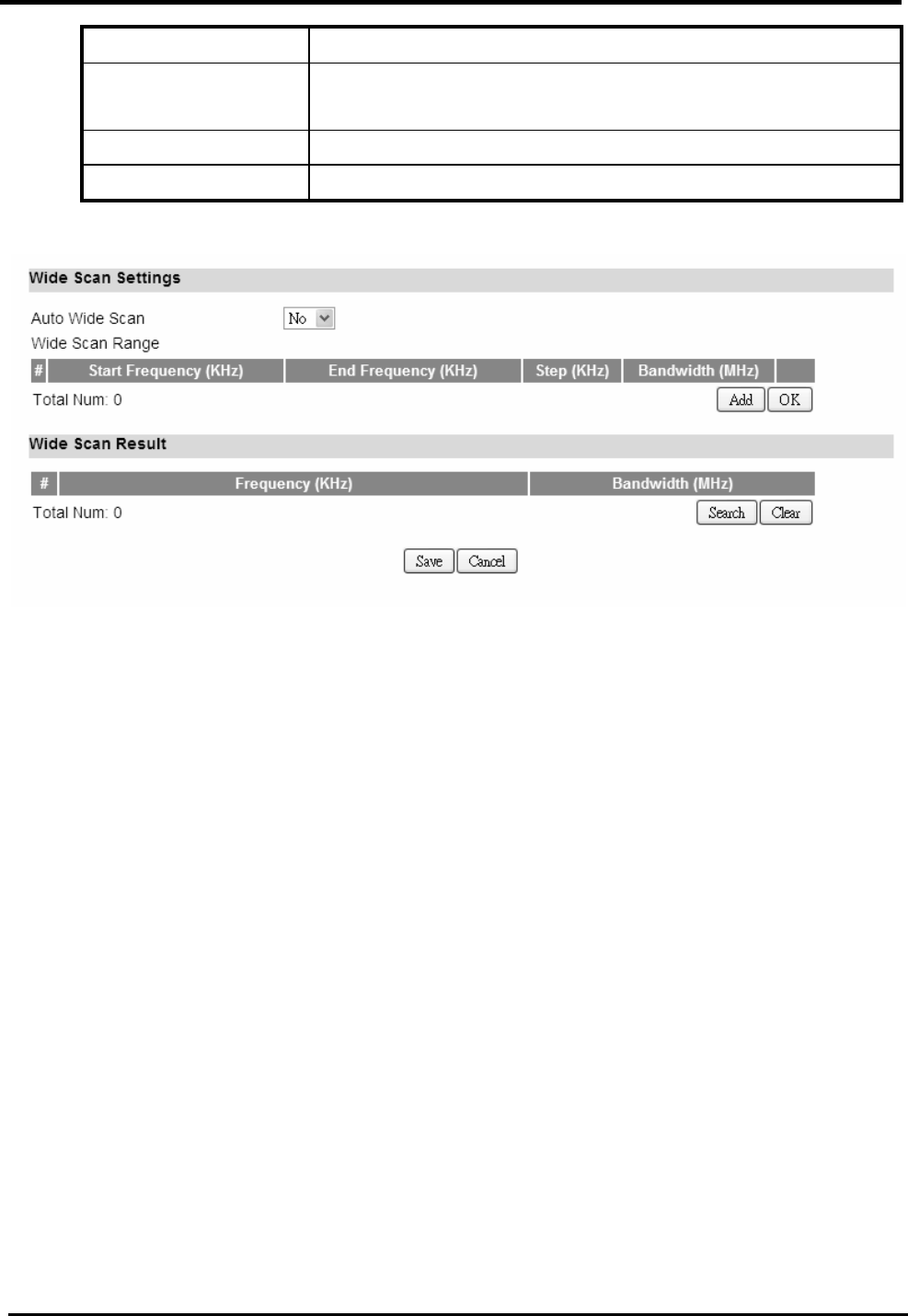
WM5347N User Manual
86
Wide Scan Result
Search Show the result of wide scan. Search button can trigger
wide scan.
Clear Clear button clear current search result.
Save/ Cancel Save/ Cancel current setting.
Figure 69. WiMAX>Wide Scan
9.4. Link Status
“WiMAX>Link Status>Link Status”
The “Link Status” menu item shows a brief profile of the current WiMAX link.
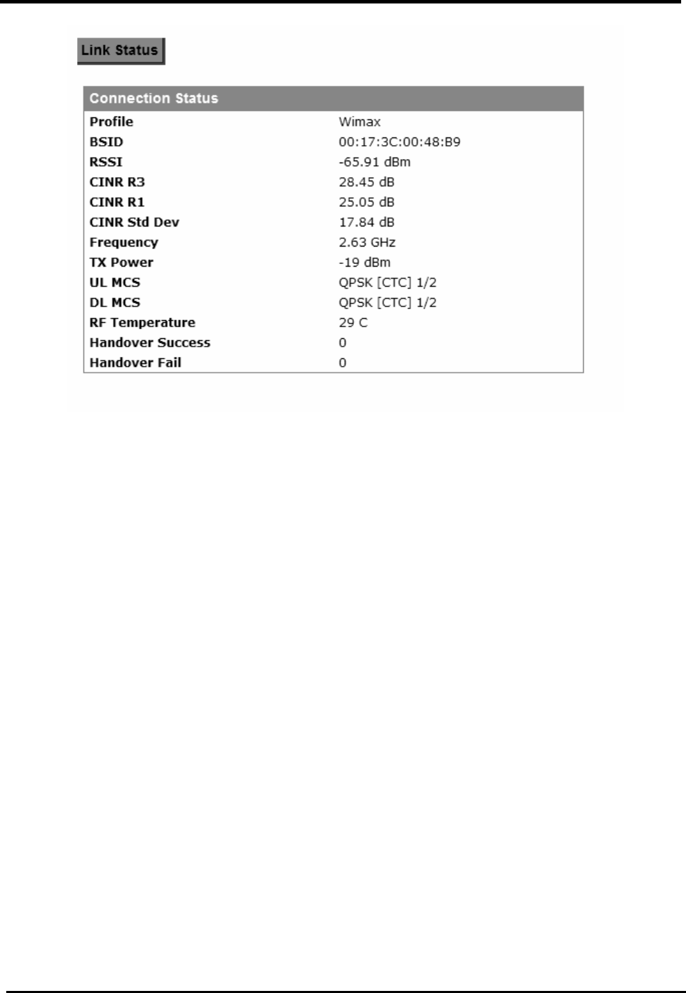
WM5347N User Manual
87
Figure 70. WiMAX Link Status
9.5. Link Statistics
“WiMAX>Link Statistics> Link Statistics”
The “Link Statistics” menu item will display statistical information in the WiMAX link.
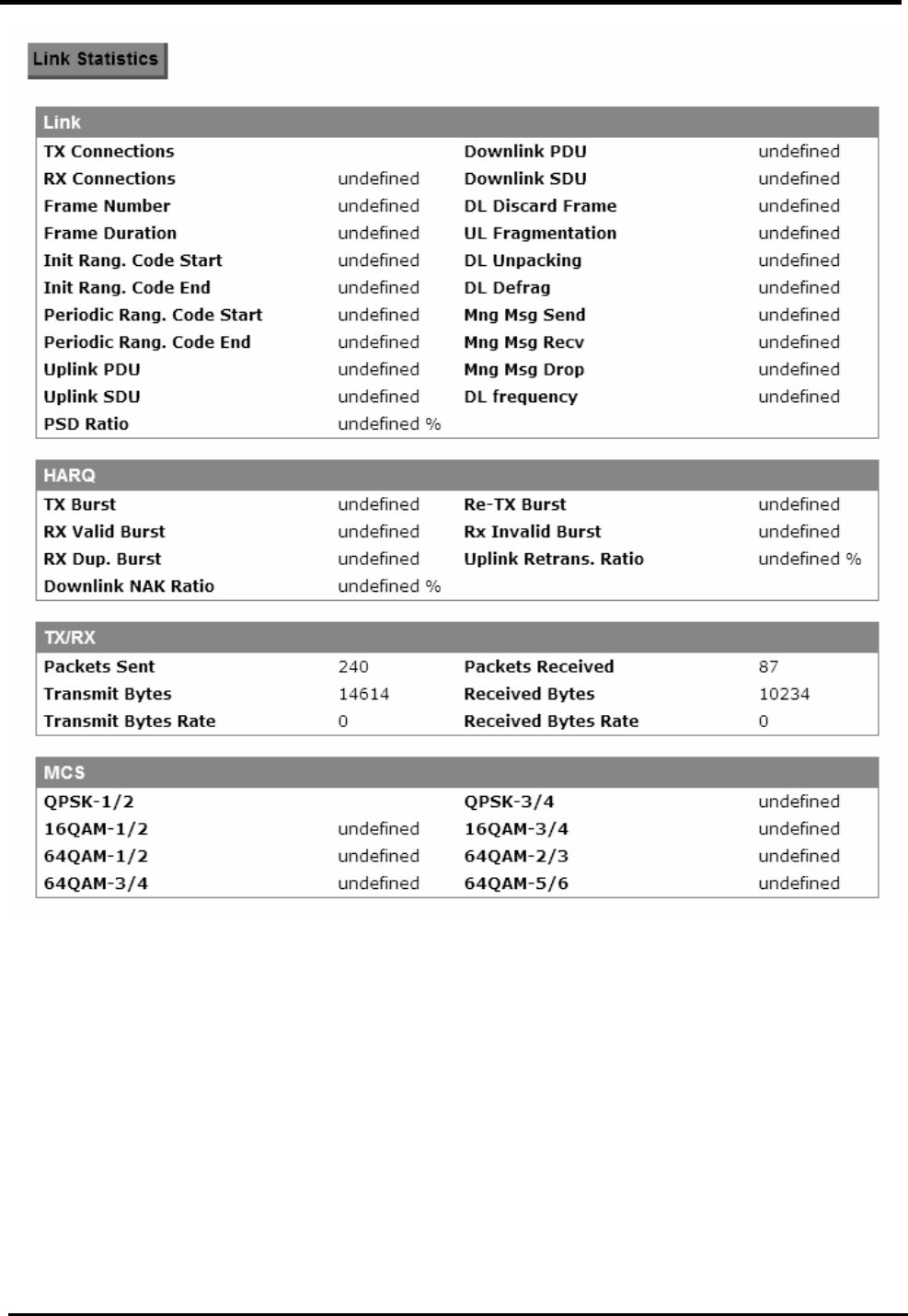
WM5347N User Manual
88
Figure 71. WiMAX Link Statistics
9.6. Connection Info
“WiMAX>Connection Info>Connection Info”
The connection info window will show the connection ID and its connection type.
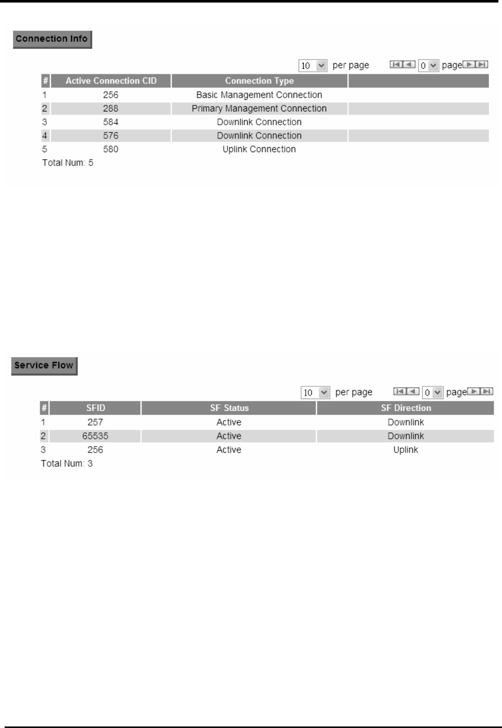
WM5347N User Manual
89
Figure 72. WiMAX Connection Info
9.7. Service Flow
“WiMAX>Service Flow>Service Flow”
The WiMAX service flow window will show the status and direction of each service flow ID.
Figure 73. WiMAX Service Flow

WM5347N User Manual
90
10. WiFi
Based on the IEEE 802.11 set of standards, WiFi provides wireless networking capabilities.
10.1. WLAN
“WiFi>WLAN”
Name Description
WLAN Settings
Enable WLAN This will enable the CPE to function as a WiFi Access
Point.
WLAN Mode Select the WLAN protocol.
WLAN Channel Select the WLAN channel. See Table 4 for Channel
description. “Auto” will allow CPE to choose the best
channel automatically.
WLAN Maximum
STA number
The maximum STA number of WLAN. It will control the
number user via WLAN to access internet.
WLAN TxPower This will control transmit power of WLAN.
WLAN TxRate This will limit transmit rate of WLAN.
WLAN Beacon
Interval
The time interval of WAN beacon.
WLAN DTIM period The period of WLAN DTIM.
WLAN RTS
Threshold
Default is 2347.
WLAN
Fragmentation
Threshold
Default is 2346.
Enable WPS Enabling the Wi-Fi Protected Setup (WPS) will allow you to
easily configure security on your wireless network.
WPS PIN When using WPS PIN mode, input the PIN (Personal
Identification Number) code read from the new wireless
client.
Multiple BSSID
number
Select how many BSSID will be created.
Configure SSID Select which BBSID to be configured.

WM5347N User Manual
91
WLAN SSID Service Set Identifier. The network name used to identify
the WLAN. All the WiFi devices on the WLAN must use the
same SSID to connect to the CPE.
Hide SSID Check the box to prevent the CPE from broadcasting its
SSID.
Encryption Type Select the encryption type. You will see further encryption
setting for the selected encryption type. For instance, if you
select WEP, then you will see WEP settings.
NONE
WEP
WPA Personal
WPA Enterprise
WEP Settings If “WEP” is selected as the encryption type, you will see the
following setting.
Authentication
Method
Two types of authentication:
OPEN SYSTEM: Open system authentication. All
clients that request access to the CPE are accepted
without actual authentication.
SHARED KEY: Shared Key authentication require the
exchange of an authentication key shared among the
CPE and clients in the network.
WEP Encryption
Length
Length of the WEP encryption key:
64-bit
128-bit
Key 1 Set the WEP key 1.
If the WEP encryption length is set to 64-bit, then use 10
hexadecimal or 5 ASCII characters as the key.
If the WEP encryption length is set to 128-bit, then use 26
hexadecimal or 13 ASCII characters as the key.
Key 2 Set the WEP key 2.
Refer to Key 1 for details.
Key 3 Set the WEP key 3.
Refer to Key 1 for details.
Key 4 Set the WEP key 4.
Refer to Key 1 for details.
WPA Settings If you select “WPA personal” or “WPA Enterprise” as the
encryption type, you will see following settings.
WPA mode Select the WPA encryption mode.

WM5347N User Manual
92
WPA
WPA2
Auto (WPA or WPA2)
Cipher Type Select the Cipher algorithm.
TKIP
AES
TKIP and AES
Pre-shared Key The pass-phrase used by WPA personal encryption mode.
The length is between 8 to 63 characters. This field is
disabled when “WPA Enterprise” is selected as the
encryption mode.
EAP (802.1X )
Settings
If “WPA Enterprise” is selected as the encryption mode,
you will see the following settings.
RADIUS Server IP
Address
The IP address of the RADIUS server.
RADIUS Server Port
The RADIUS server port number.
RADIUS Server
Shared Secret
A case-sensitive password used to validate
communications between a RADIUS server and CPE.
Save & Start WPS
PIN
Save the configuration and then start the WPS PIN
process (need to input WPS PIN field first).
Save & Start WPS
PBC
Save the configuration and then start the WPS PBC
process.
Save Commit the changes made and save to CPE device.
Cancel Reset fields to the last saved values.
NOTE: When WPS is selected, you will have 3 Save options. If you click “Save” button, it will save
the configuration without starting the WPS process. If you select the “Save & Start WPS PIN” or
“Save & Start WPS PBC”, it will save the configuration and start the WPS process selected at that
time.
Frequency(GHZ) Channel
Auto Auto select the best channel
2.452 Channel 9
2.457 Channel 10
2.462 Channel 11
2.467 Channel 12
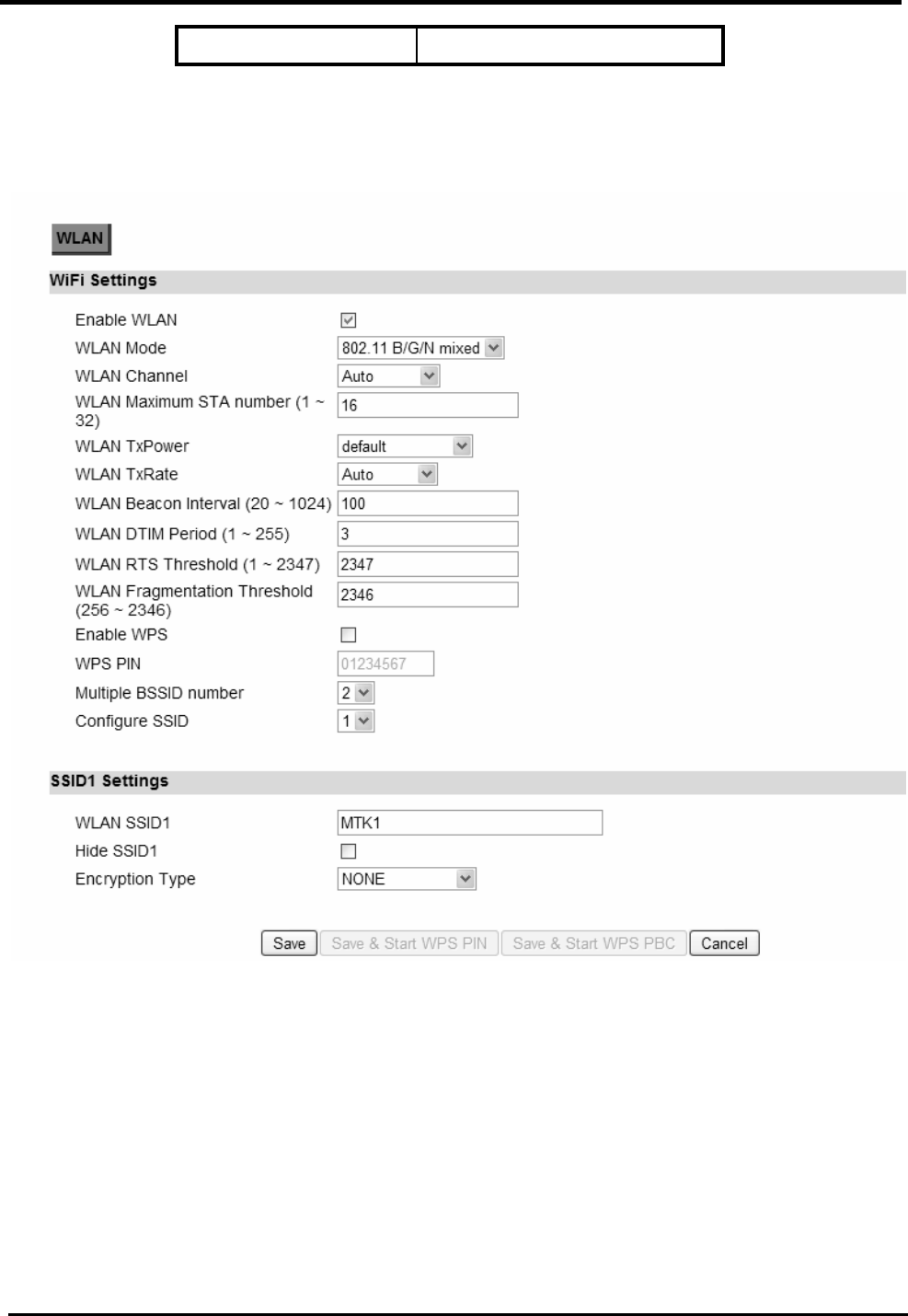
WM5347N User Manual
93
2.472 Channel 13
Table 4: WLAN Channel
Figure 74. WiFi>WLAN NONE
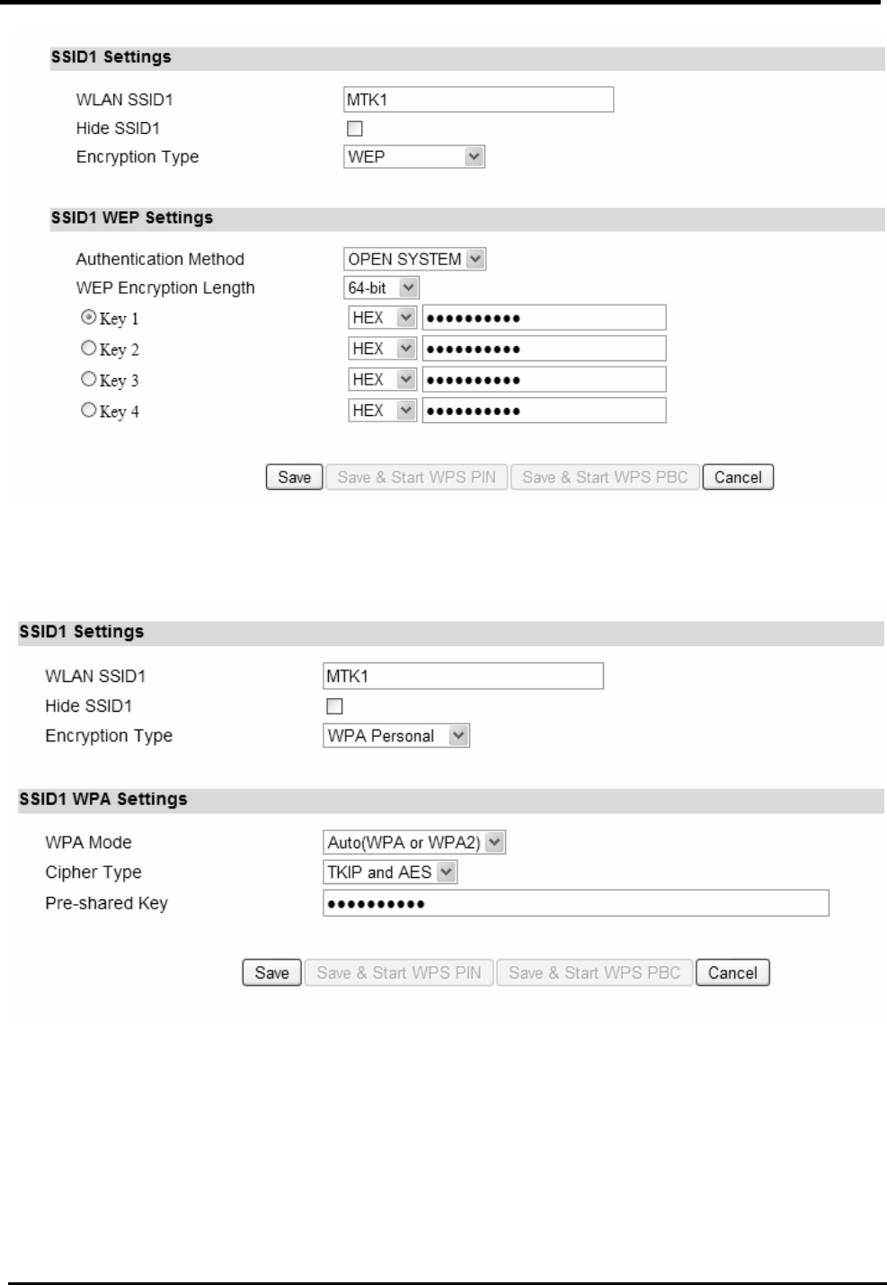
WM5347N User Manual
94
Figure 75. WiFi>WLAN WEP
Figure 76. WiFi>WLAN Personal
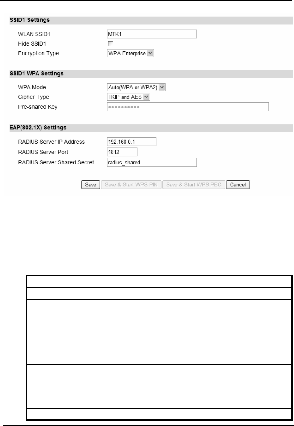
WM5347N User Manual
95
Figure 77. WiFi>WLAN Enterprise
10.2. MAC Address Filter
“WiFi>MAC Address Filter”
Name Description
MAC Filter Setup
Enable MAC
address Filter
Check the box to enable MAC address filter
Mode Deny listed stations: Deny WiFi access from the stations
listed in MAC Filter Rules.
Allow listed stations: Allow WiFi access from the
stations listed in MAC Filter Rules.
MAC Filter Rules
Add Click this button to create a MAC filter rule. Enter the MAC
address in the following format.
00:00:00:00:00:00 xx:xx:xx:xx:xx:xx
OK Click this button to finish edition for table entries.
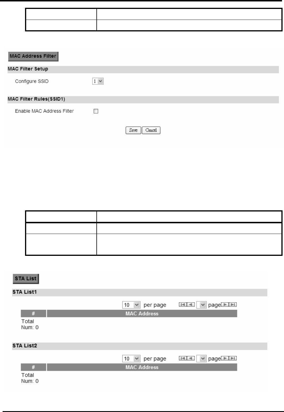
WM5347N User Manual
96
Save Commit the changes made and save to CPE device.
Cancel Reset fields to the last saved values.
Figure 78. WiFi>MAC Address Filter
10.3. STA List
“WiFi>STA List”
Name Description
STA List
This list observe MAC address of the user who access
WLAN.
Figure 79. WiFi>STA List

WM5347N User Manual
97

WM5347N User Manual
98
11. Administrator
11.1. Remote Control
Remote access is the ability to get access to CPE from a remote computer or network. CPE supports
six different types of remote access protocols.
HTTP allows you to set the port and configure both HTTP and HTTPS protocols
TELNET typically provides access to a command-line interface on a remote machine
SSH Secure Shell (SSH) is a network protocol used to allow remote connections
between two devices using a secure channel. It uses public-key cryptography to
authenticate the remote entity. An SSH server, by default, listens on the standard TCP
port 22.
SNMP is typically used for network management to monitor network-attached devices for
conditions that warrant administrative assistance or to view and retrieve network
statistical information.
TR-069 Using TR-069 the terminals can communicate with the Auto Configuration
Servers (ACS) and establish the configuration automatically.
OMA-DM Using OMA-DM the terminals can communicate with the OMA-DM Server and
establish the configuration automatically.
11.1.1. HTTP
“Administration>Remote Control>HTTP”
Name Description
HTTP Server
Enable Check the box to allow http connections.
Port Number Enter the http port number (default is port 80).
HTTPS Server
Enable Check the box to allow https connections.
Port Number Enter the https port number (default is port 443).
HTTP and HTTPS
Allow Connection
from WAN
Check the check-box to allow connections from WAN.
Save Commit the changes made and save to CPE device.
Cancel Reset fields to the last saved values.

WM5347N User Manual
99
Figure 80. Administration>Remote Control>HTTP
11.1.2. TELNET
“Administration>Remote Control>TELNET”
Name Description
TELNET Server
Enable Check the box to allow Telnet connections.
Port Number Enter the Telnet port number (default is port 23).
Allow Connection
from WAN
Check the check-box to allow connections from WAN.
Save Commit the changes made and save to CPE device.
Cancel Reset fields to the last saved values.
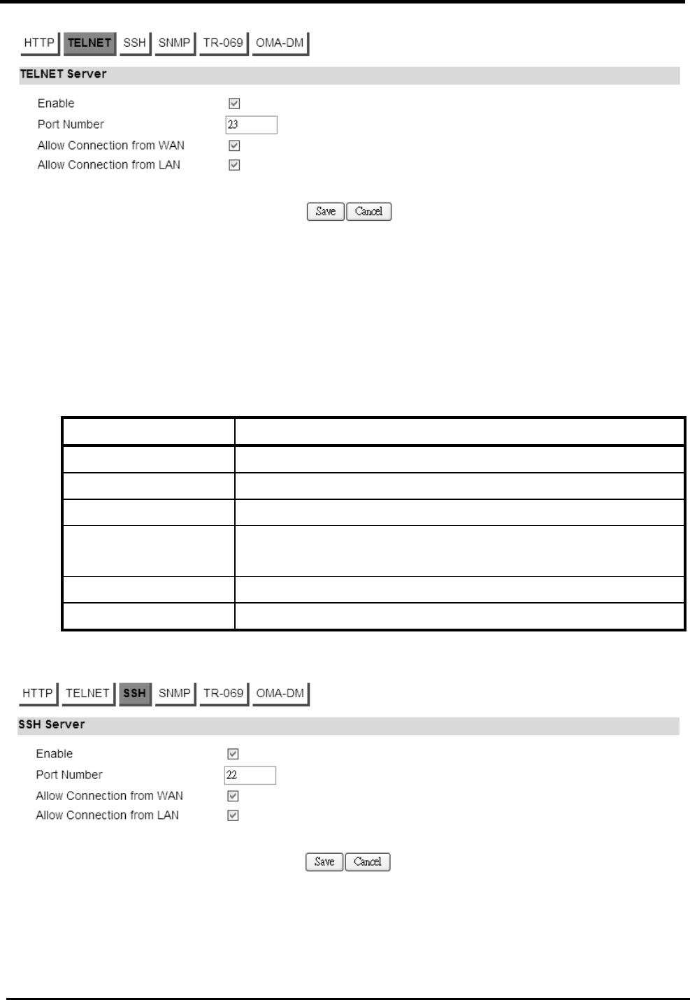
WM5347N User Manual
100
Figure 81. Administration>Remote Control>TELNET
11.1.3. SSH
“Administration>Remote Control>SSH”
Name Description
SSH Server
Enable Check the box to allow SSH connections.
Port Number Enter the SSH port number (default is port 22).
Allow Connection
from WAN
Check the check-box to allow connections from WAN.
Save Commit the changes made and save to CPE device.
Cancel Reset fields to the last saved values.
Figure 82. Administration>Remote Control>SSH
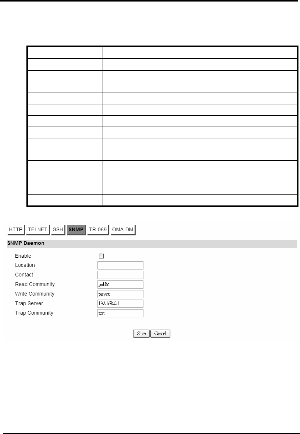
WM5347N User Manual
101
11.1.4. SNMP
“Administration>Remote Control>SNMP”
Name Description
SNMP Daemon
Enable Checking the enable button will allow SNMP applications
to query and set some of the SNMP variables.
Location Enter the Location SNMP string variable.
Contact Enter the Contact SNMP string variable.
Read Community Enter the Read community string to query SNMP data.
Write Community Enter the Write community string to set SNMP variables.
Trap server Enter the IP Address of trap server where you want trap
notifications to be sent to.
Trap Community Enter the Trap community to act as a password for sending
trap notifications to the target SNMP manager.
Save Commit the changes made and save to CPE device.
Cancel Reset fields to the last saved values.
Figure 83. Administration>Remote Control>SNMP

WM5347N User Manual
102
11.1.5. TR-069
Using TR-069 the terminals can communicate with the Auto Configuration Servers (ACS) and
establish the configuration automatically. It’s the current standard for activation of terminals in the
DSL broadband market.
“Administration>Remote Control>TR-069”
Name Description
TR-069 Configuration
Enable To enable or disable the TR-069 on the CPE.
ACS Server URL The ACS URL for the CPE to connect to.
ACS Username The username for the CPE when connected to ACS.
ACS Password The password for CPE when connected to ACS.
Periodical inform Enable
To enable or disable the periodical inform to ACS for
the CPE.
Periodical inform
Interval
The interval between two periodical inform.
Connection Request
Username
Enter the username for the ACS to perform connection
request to the CPE.
Connection Request
Password
Enter the password for the ACS to perform connection
request to the CPE.
CA Certificate File The CA certificate file is used to identify the certificate
of ACS when CPE communicated ACS with HTTPS
URL.
CA Certificate Info Displays the subject field of the CA Certificate.
CLIENT Certificate File The CLIENT certificate file is used when CPE
communicates with HTTPS URL.
CLIENT Certificate Into Displays the subject field of the CLIENT Certificate.
Save Commit the changes made and save to CPE device.
Cancel Reset fields to the last saved values.
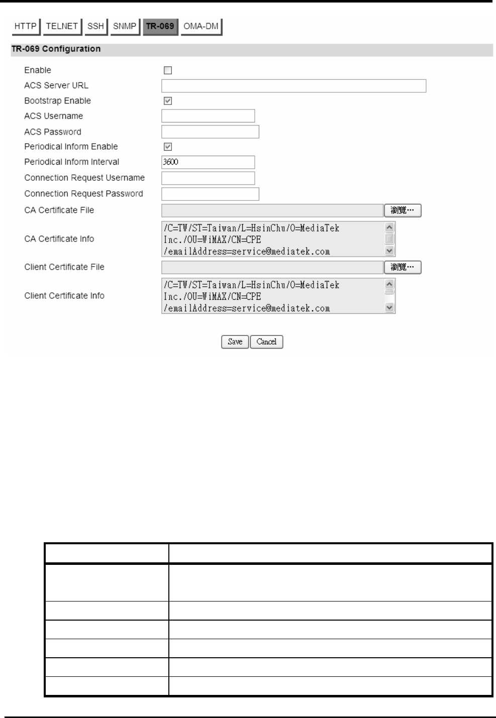
WM5347N User Manual
103
Figure 84. Administration>Remote Control>TR-069
11.1.6. OMA-DM
Using OMA-DM the terminals can communicate with the OMA-DM Server and establish the
configuration automatically. It’s the current standard for activation of terminals in OMA (Open Mobile
Alliance).
“Administration>Remote Control>OMA-DM”
Name Description
OMA DM
Configuration
Enable To enable or disable the OMA-DM activity of the CPE.
Server URL The DM Server URL for the CPE to connect to.
Server Port The DM Server Port for the CPE to connect to.
Server Auth Type The DM Server authentication type.
Server ID The server ID for the CPE when connected to the DM
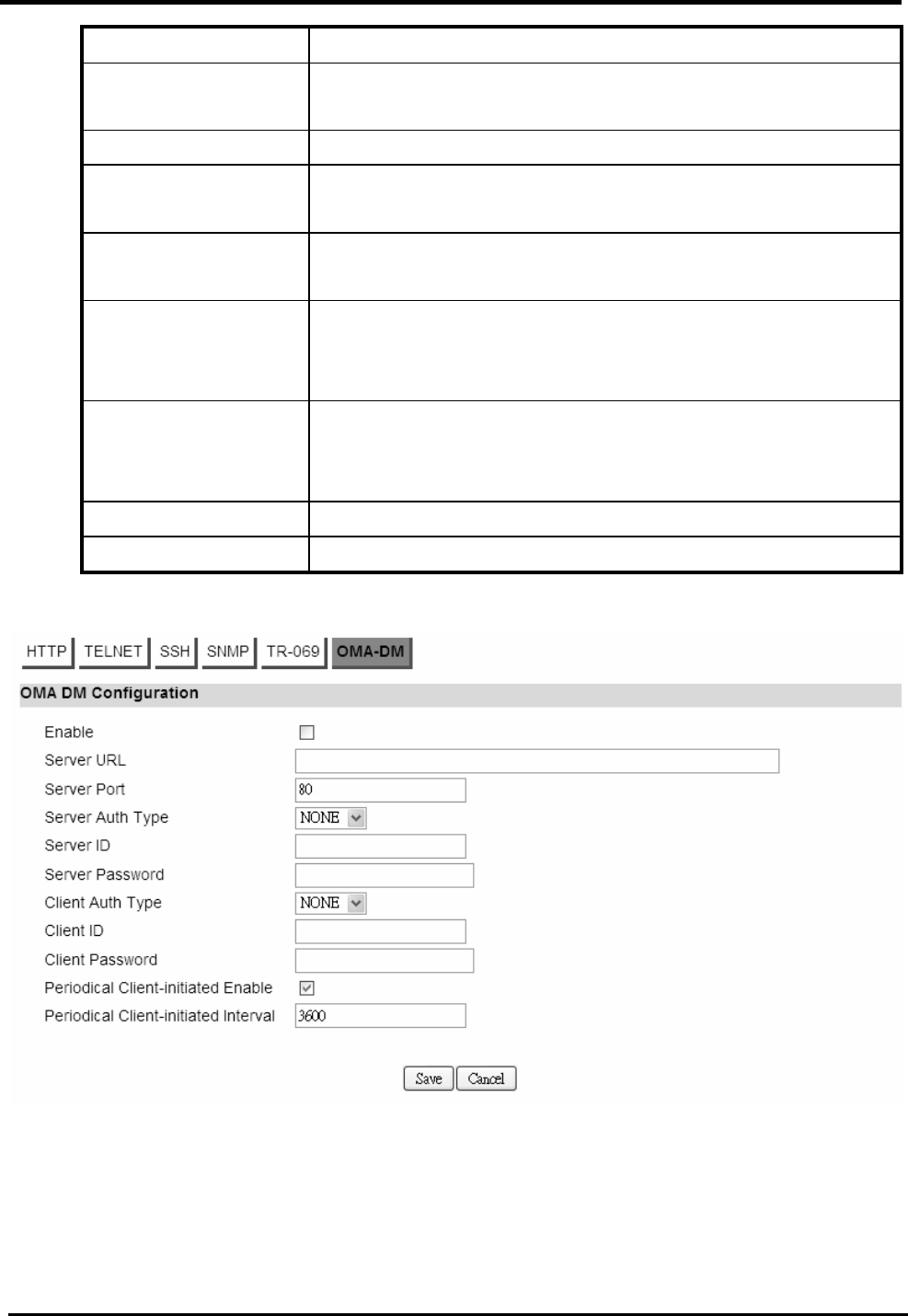
WM5347N User Manual
104
Server.
Server Password The server password for the CPE when connected to the
DM Server.
Client Auth Type The DM Client authentication type.
Client ID The client ID for the CPE when connected to the DM
Server.
Client Password The client password for the CPE when connected to the
DM Server.
Periodical
Client-initiated
Enable
To enable or disable the periodical client-initialed session
to DM Server for the CPE.
Periodical
Client-initiated
Interval
The interval between two periodical client-initiated
sessions.
Save Commit the changes made and save to CPE device.
Cancel Reset fields to the last saved values.
Figure 85. Administration>Remote Control>OMA-DM

WM5347N User Manual
105
11.2. Password
NOTE: The default usernames and passwords are admin/admin and guest/guest.
The user with administrative privileges (belonging to the “admin” group) has access to all the
features in the software. A user with “guest” privileges (belonging to the “guest” group) only has a
subset of the features available to them.
“Administration>Password>Password”
NOTE: There can only be one username in each of the groups (one to one relationship).
Name Description
Change Password
Group Select which group the user belongs to that you would like
to change the password for.
admin, if the user is part of the admin group, they have
full access to all the feature.
guest, if the user is part of the guest group, they have
limited access to the features.
Old Password Enter the old password.
New Password Enter the new password.
Retype Retype the new password.
Save Commit the changes made and save to CPE device, it will
only commit the change made to the password.
Cancel Reset fields to the last saved values.
Change Username
Group Select which group the user belongs to that you would like
to change the username for.
admin, if the user is part of the admin group, they have
full access to all the feature.
guest, if the user is part of the guest group, they have
limited access to the features.
Old Username Enter the username you want to change
New Username Enter the new username
Password Enter the original password, the password will not change.
If you enter an incorrect or different password, the change
will not be committed.
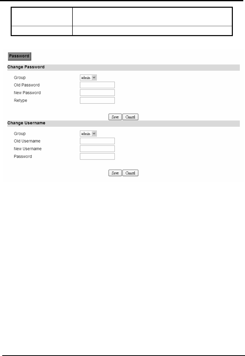
WM5347N User Manual
106
Save Commit the changes made and save to the CPE device, it
will only commit the change made to the username.
Cancel Reset fields to the last saved values.
Figure 86. Administration>Password

WM5347N User Manual
107
12. System
12.1. Date and Time
You can configure the date and time on the device. The user can manually configure the system time,
or choose to get the date and time from a time server. The “Save” button will commit the
configuration, and the “Cancel” button will clear the fields. The “Time Zone” tab will allow you to set
the time zone and set the starting and finish time for daylight saving period. You can also enable or
disable “Daylight Savings Time”.
NOTE: If you don’t configure the time on the CPE it will use the default system starting time. The
default starting time is set to 1970/1/1 00:00:00.
12.1.1. Date
“System>Date/Time>Date”
Name Description
Time and Date Setup
Manual If you select the Manual option, then you are to enter the
time and date manually.
New Time New time manually entered.
New Date New date manually entered.
Get From Time Server
If you select this option it will get the local time from a
time server automatically.
Time Protocol Select the Time protocol.
Time Server Address Enter the address of the time server.
Save Commit the changes made and save to CPE device.
Cancel Reset fields to the last saved values.

WM5347N User Manual
108
Figure 87. System>Date/Time>Date
12.1.2. Time Zone
“System>Date/Time>Time Zone”
Name Description
Time Zone Setup
Time Zone Enter the time zone of for your location.
Enable Daylight
Savings
If you want to enable Daylight Savings Time, check the
box.
Start Date Enter the beginning date for Daylight Savings time.
End Date Enter the end date for Daylight Savings time.
Save Commit the changes made and save to CPE device.
Cancel Reset fields to the last saved values.

WM5347N User Manual
109
Figure 88. System>Date/Time>Time Zone
12.2. Upgrade Firmware
The “Upgrade” window allows you to upgrade the firmware on you device. Users can choose to
upgrade the firmware by entering the file path or entering the URL of the upgrade file.
NOTE: After pressing the “Upgrade” button, it will automatically reboot the CPE and upgrade the
firmware with the specified file. You will be prompted to login to the CPE after the upgrade is
complete.
12.2.1. Upgrade File
“System>Upgrade Firmware>Upgrade File”
Name Description
Upgrade Firmware
Browse Enter the full path of the file you want to upgrade. The
“browse” button will help you find on your server.
Upgrade It will start upgrading the file.
Status The status bar will display which segment it’s processing
and what percentage of the upgrade has been completed.
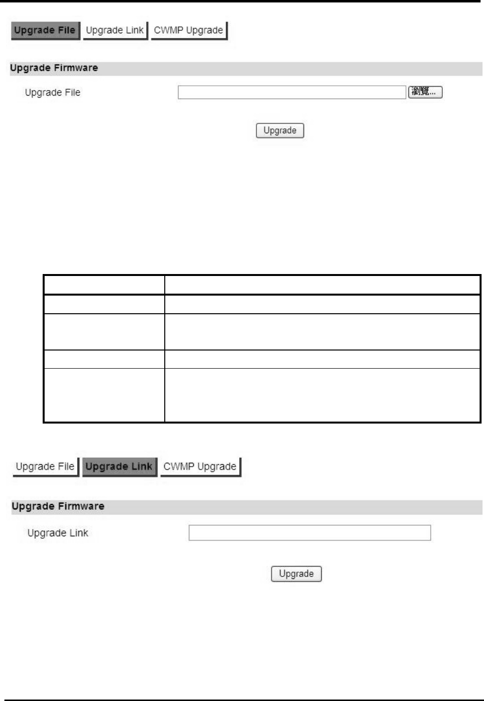
WM5347N User Manual
110
Figure 89. System>Upgrade Firmware>Upgrade File
12.2.2. Upgrade Link
“System>Upgrade Firmware>Upgrade Link”
Name Description
Upgrade Firmware
Upgrade Link Enter the complete URL path of the file you want to
upgrade.
Upgrade It will start upgrading the file.
Status The status window will display which segment it’s
processing and what percentage of the upgrade has been
completed.
Figure 90. System>Upgrade Firmware>Upgrade Link
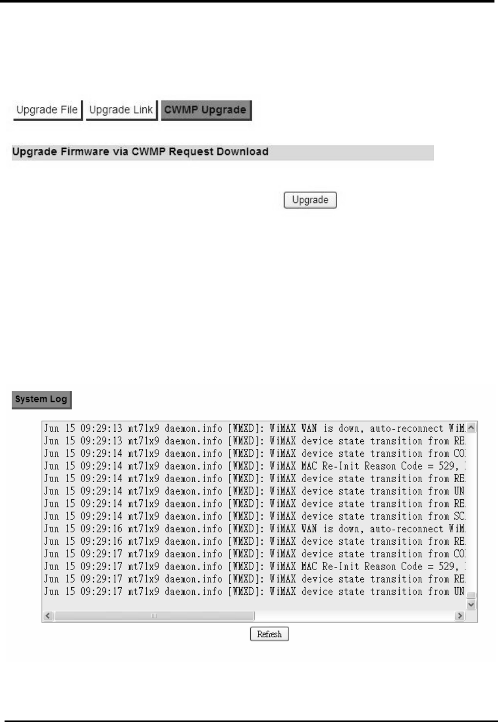
WM5347N User Manual
111
12.2.3.
“System>Upgrade Firmware>CWMP Upgrade”
Press “Upgrade” button to upgrade firmware.
Figure 91. System>Upgrade Firmware>CWMP Upgrade
12.3. Log
The “System>Log” will display system log output. The “Refresh” button will clear the log window and
display the most current system log information.
Figure 92. System>Log
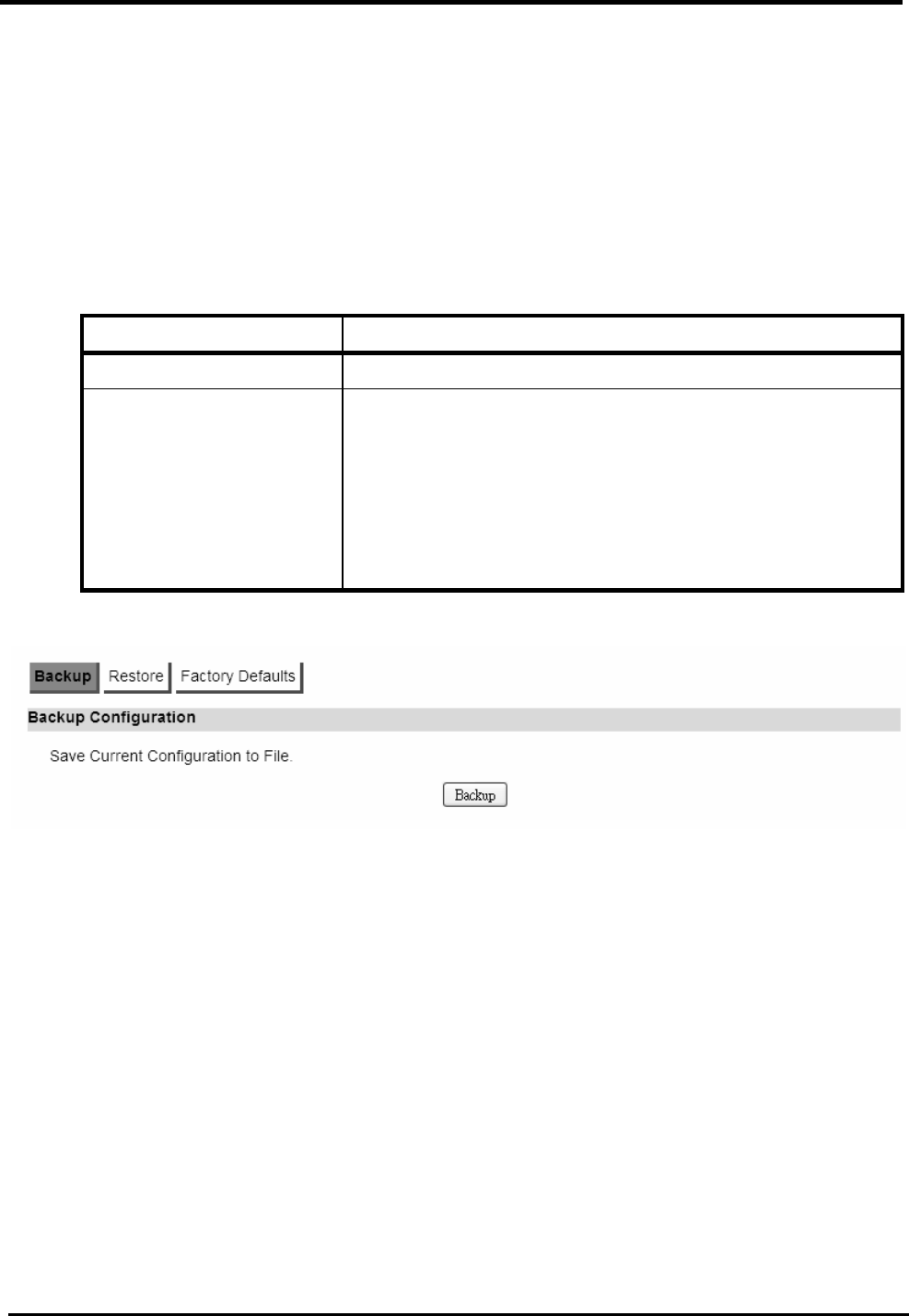
WM5347N User Manual
112
12.4. Backup/Restore
The Backup/Restore tab will allow you to save and restore your configuration on the CPE. You can
also reset the CPE to factory defaults from the “Factory Defaults” tab.
12.4.1. Configuration Backup
“System>Backup/Restore>Backup”
Name Description
Backup Configuration
Backup Click the “Backup” button to save the current
configuration on the CPE. After you click the “Backup”
button “File Download” window will pop-up and prompt
you to save the file. In the “Save As” window, enter the
name and location, where you wish to download the file
to.
Figure 93. System>Backup/Restore>Backup
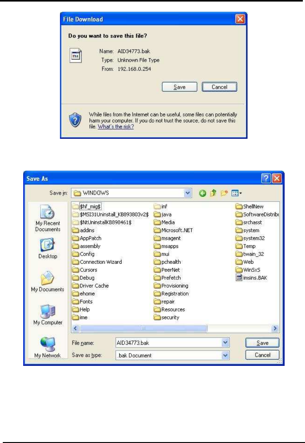
WM5347N User Manual
113
Figure 94. File Download
Figure 95. Save File As
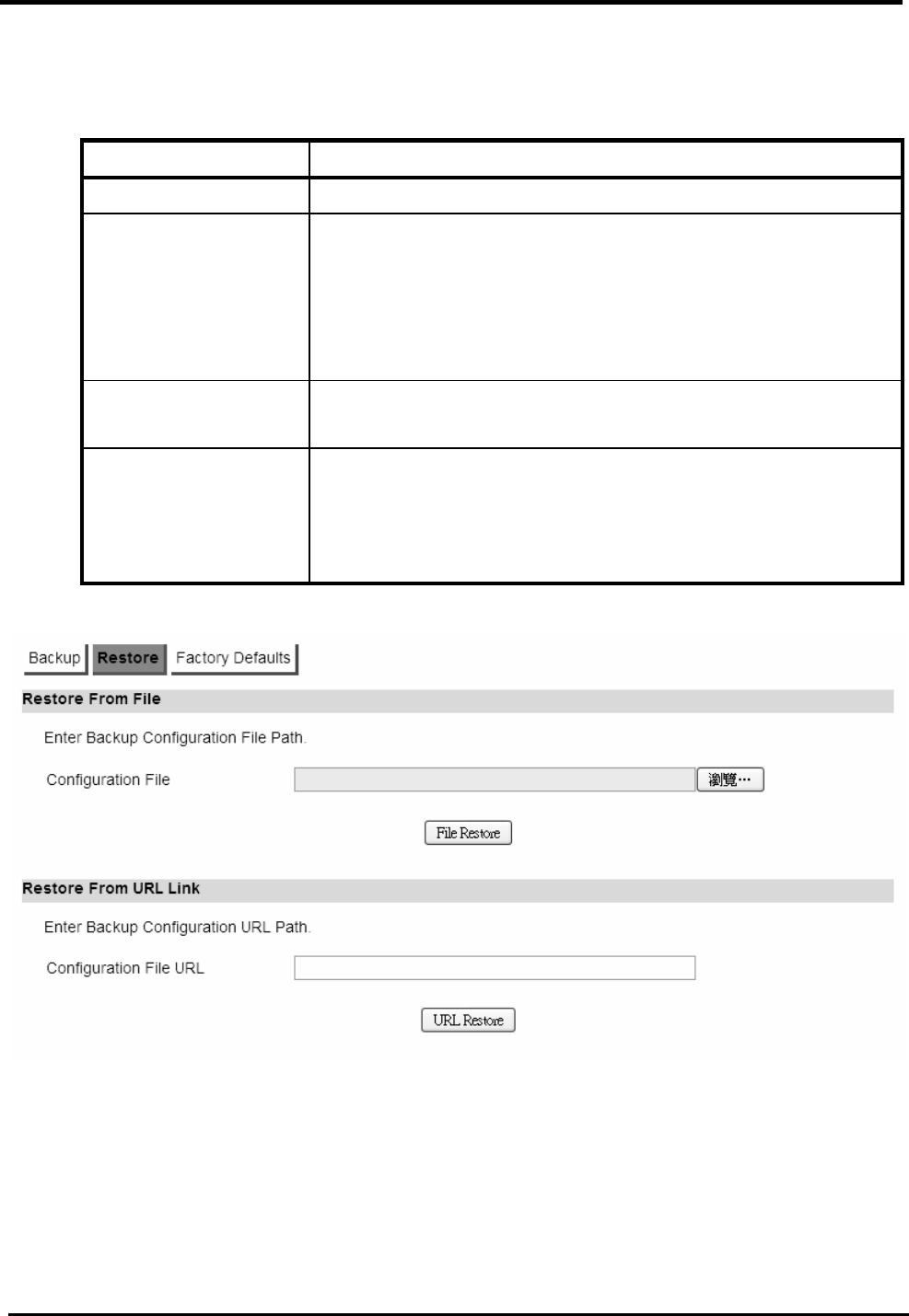
WM5347N User Manual
114
12.4.2. Configuration Restore
“System>Backup/Restore>Restore”
Name Description
Restore From File
File Restore Enter the path of the configuration file you wish to restore.
Click on the “Browse” button to help you navigate through
directories and search for the file. After you enter the
complete file path, click the “File Restore” button, It will
begin restoring the configuration from the file specified.
Restore From URL
Link
URL Restore Enter the configuration URL path you wish to restore from.
After you enter the complete URL path, click the “URL
Restore” button. It will begin restoring the configuration
from the URL location you specified.
Figure 96. System>Backup/Restore>Restore
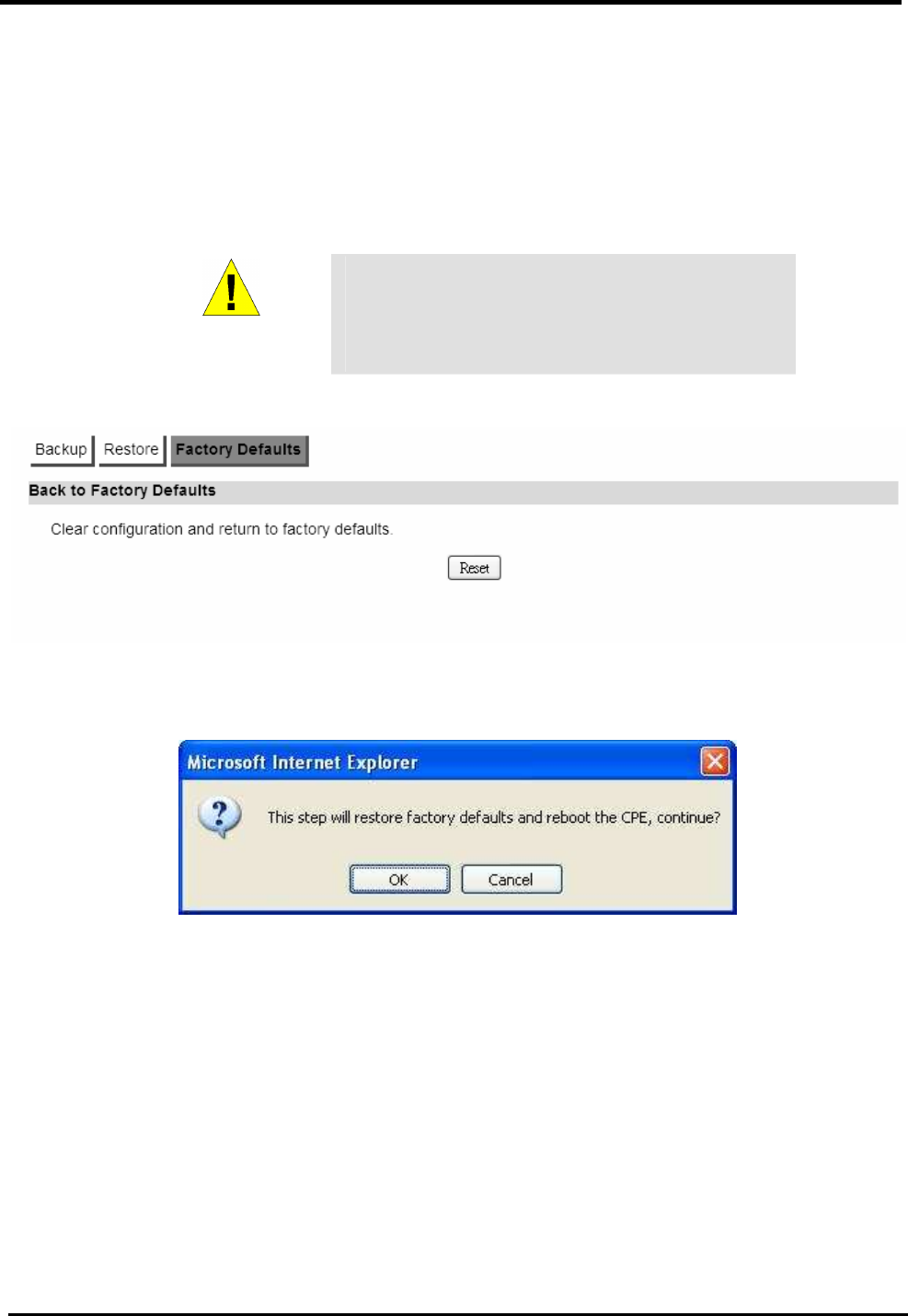
WM5347N User Manual
115
12.4.3. Factory Defaults
“System>Backup/Restore>Factory Defaults”
Factory default will set all the configurations back to factory defaults. Any configurations that you
have made will be changed back to the factory default settings. After selecting “Reset” button, you
will be prompted with a window to confirm or cancel the action.
WARNING
Restore factory defaults will clear any
IP addresses and setting you may have
configured on the CPE.
Figure 97. System>Backup/Restore>Factory Defaults
Figure 98. Restore to Factory Default Warning