Teka Induction Hobs Iq 640 Users Manual 61401142.qxp
2015-02-05
: Teka Teka-Induction-Hobs-Iq-640-Users-Manual-395132 teka-induction-hobs-iq-640-users-manual-395132 teka pdf
Open the PDF directly: View PDF ![]() .
.
Page Count: 32
INSTALLATION INSTRUCTIONS
AND RECOMMENDATIONS FOR USE AND MAINTENANCE
INDUCTION HOBS
EINBAU-ANLEITUNG
UND EMPFEHLUNGEN FÜR GEBRAUCH UND INSTANDHALTUNG
INDUKTIONSKOCHFELD
INSTRUCTIONS POUR L’INSTALLATION
ET RECOMMANDATIONS D’UTILISATION ET D’ENTRETIEN
PLAQUES À INDUCTION
IR 622 - IZ 622 - IT 622 - IT 635 - IR 635 - IT 645
IR 645 - IR 735 AB - IR 604 - IQ 640 - IQ 644

Contents / Inhalt / Table des Matières
GB
Introduction
User Guide
Installation
Positioning the hob
Fastening the hob
Connecting the electricity
Technical information
Dimensions and characteristics
Use and Maintenance
Before starting for the firts time
Touch Control User Instructions
Suggestions and recommendations
Cleaning and care
If something doesn’t work
Locking the hob sensors
Function for keeping a container hot
Power supplied according
to the level selected
Detecting pans
Heat-up
The Power function
Disconnection for safety purposes
Timer function
The clock as a countdown timer
Overheating safety feature
Power surges
Page 5
8
9
9
10
11
12
12
13
13
13
15
16
16
16
16
18
19
19
20
21
21
21
22
25
Tipps und Empfehlungen
Reinigung und Pflege
Im Störungsfall
Präsentation
Hinweise zur Benutzung
der Gebrauchsanweisung
Einbau
Einbauort für das Kochfeld
Verankerung des Kochfelds
Elektrischer Anschluss
Technische Angaben
Abmessungen und Eigenschaften
Gebrauch und Instandhaltung
Besondere Vorbedingungen für die
Inbetriebnahme
Gebrauchsanleitung für die
TOUCH CONTROL
Funktion zur Erhaltung der
Behälterwärme
Energiezufuhr gemäß gewählter
Leistungsstufe
Kochgeschirrerkennung
Elektronische Ankochautomatik
Power-Funktion
Automatische Sicherheits-
Abschaltung
Timerfunktion
Verwendung der Zeitanzeige als
Kurzzeitwecker
Überhitzungsschutz
Überspannungen im Stromnetz
Seite 5
27
28
28
29
30
31
31
32
32
32
34
Présentation
Guide d’utilisation
Installation
Logement des plaques de cuisson
Ancrage de la plaque de cuisson
Branchement électrique
Informations techniques
Dimensions et caractéristiques
Utilisation et entretien
Conditions spéciales avant la
mise en marche
Instructions d’utilisation de
la commande sensitive
Suggestions et recommandations
Nettoyage et stockage
Si quelque chose ne fonctionne pas
Blocage des capteurs sensitifs de la
plaque de cuisson
Fonction pour garder un récipient chaud
Énergie fournie selon le niveau de
puissance sélectionné
Détection de récipients
Programmation de cuisson
Fonction Power
Déconnexion de sécurité
Fonction minuteur
L'horloge est utilisée en tant que
compte à rebours
Sécurité face aux surchauffes
Surtensions sur la ligne
Page 5
47
48
48
49
50
51
51
52
52
52
DE
FR
Sperrung der Sensoren des
Kochfelds
54
55
55
55
56
57
58
59
60
61
61
61
62
65
35
35
35
36
37
38
39
40
41
41
41
42
45

5
Introduction / Einführung / Présentation
Notes about the cookware to use on your
induction hob
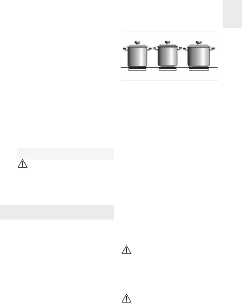
The size of the bottom of the cookware to be
used should be big enough to completely cover
the cooking area drawn on the glass.
Depending on the type of cookware (material
and size), the induction areas can work with
smaller cookware.
Please remember that the induction elements
only work with cookware that has a ferromag-
netic (material attracted by a magnet) bottom.
Always use pans with a smooth, flat
base on the induction hotplates. Using pans
with a deformed, concave or undulating
base will cause overheating that may dama-
ge the glass or the pan itself.
Bear in mind that the pan being used
may have a considerable influence on the
performance of any induction hotplate. You
may come across pans on the market that,
although specified as suitable for induction,
perform poorly or present problems when it
comes to being recognised by the induction
hotplate due to the lack of or poor quality of
the ferromagnetic material on the base of
the pan.
Anmerkungen zum Kochgeschirr für Ihr
Induktionskochfeld
Der Boden des Kochgeschirrs muss ausreichend
groß sein, um die auf der Glaskeramik markierten
Kochflächen vollständig zu bedecken.
Je nach Art des Kochgeschirrs (Material und
Größe) können die Kochflächen auch mit klei-
neren Behältern funktionieren.
Bitte bedenken Sie, dass zum Betrieb der
Induktionskochflächen Kochgeschirr mit ferro-
magnetischen Böden (magnetischem Material)
verwendet werden muss.
Für Induktionszonen immer Kochges-
chirr mit flachem und glattem Boden ver-
wenden. Kochschirr mit unebenem, konka-
vem oder gewelltem Boden verursacht Über-
hitzung, die zu Schäden an der Glaskeramik
oder am Kochgeschirr führen kann.
Bitte beachten Sie, dass die Wahl des
Kochgeschirrs einen großen Einfluss auf die
Leistungsfähigkeit jeglicher Art von Induk-
tionskochplatten hat. Es wird Kochgeschirr
angeboten, auf dem angegeben wird, dass
es für das induktive Kochen geeignet ist und
das nichtsdestotrotz aufgrund der schlech-
ten Qualität des ferromagnetischen Mate-
rials des Kochgeschirrbodens über eine
äußerst geringe Leistungsfähigkeit verfügt
und von der Induktionskochplatte nur sch-
werlich erkannt wird.
Remarques sur les récipients à utiliser sur
les plaques à induction
Le fond du récipient à employer doit avoir une
taille telle qu'elle couvre complètement la zone
de cuisson dessinée sur la vitre.
En fonction du type de récipient (matériel et tai-
lle) les zones à induction peuvent fonctionner
avec des récipients plus petits.
Tenez compte du fait que pour fonctionner, les
plaques à induction ont besoin de récipients à
fond ferromagnétiques (matériau attiré par un
aimant).
Utilisez toujours des récipients à fond
plat et lisse sur les plaques à induction. L'u-
tilisation de récipients à fond déformé, con-
cave ou ondulé provoque des surchauffes
qui peuvent endommager le verre ou le réci-
pient.
Tenez compte du fait que le récipient
que vous utilisez peut avoir beaucoup d'in-
fluence sur le rendement de n'importe quelle
plaque à induction En effet, vous trouverez
sur le marché un grand nombre de récipients
qui, bien que signalés comme appropriés
pour l'induction, ont un rendement très faible
ou ne sont pas correctement reconnus par la
plaque à induction. Ceci est du à la faible
quantité en matériau ferromagnétique de leur
fond ou à sa qualité.
GB
DE
FR
6
Model IR 622 / IT 622
12300 / 3200* W induction hotplate
2700 / 2100 W double circuit radiant hotplate.
31400 / 1800* W induction hotplate
41500 W radiant hotplate.
* Induction power with the Power function enabled.
- Residual heat indicator (H)
- Maximum electric power: 7300 watts.
- Maximum induction power: 3700 watts.
- Supply power: 230 Volts.
- Frequency: 50/60 Hertz.
- Induction frequency: 20 to 60 kilohertz
Modell IR 622 / IT 622
1Induktions-Kochzone mit 2300 / 3200* W
2Zweikreis-Strahlungs-Kochzone mit 700 / 2100 W
3Induktions-Kochzone mit 1400 / 1800* W
4Strahlungs-Kochzone mit 1500 W
* Induktionsleistung bei aktivierter Power-Funktion.
- Restwärme-Anzeige (H)
- Maximale elektrische Leistung: 7300 W
- Maximale Induktionsleistung: 3700 W
- Versorgungsspannung: 230 V
- Frequenz: 50/60 Hz
- Induktionsfrequenz: 20 bis 60 Kilohertz.
Modèle IR 622 / IT 622
1Plaque à induction de 2.300 / 3.200* W
2Plaque rayonnante à double foyer de 700 /
2.100 W.
3Plaque à induction de 1.400 / 1.800* W
4Plaque rayonnante de 1.500 W.
* Puissance d'induction lorsque la fonction "Power"
est activée.
- Témoin de chaleur résiduelle (H)
- Puissance électrique maximale: 7.300 Watts.
- Puissance maximale d'induction: 3.700 Watts.
- Tension d'alimentation: 230 Volts.
- Fréquence: 50/60 Hertz.
- Fréquence d'induction : 20 à 60 kilohertz.
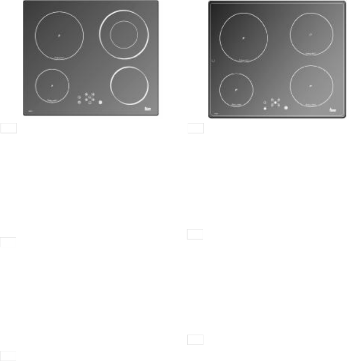
Model IT 645 / IR 645
12200 / 3200* W induction hotplate
21800 / 2500* W induction hotplate
31400 / 1800* W induction hotplate
41800 / 2500* W induction hotplate
* Induction power with the Power function enabled.
- Residual heat indicator (H)
- Maximum induction power: 7200 watts.
- Supply power: 230 Volts.
- Frequency: 50/60 Hertz.
- Induction frequency: 20 to 60 kilohertz.
Modell IT 645 / IR 645
1Induktions-Kochzone mit 2200 / 3200* W
2Induktions-Kochzone mit 1800 / 2500* W
3Induktions-Kochzone mit 1400 / 1800* W
4Induktions-Kochzone mit 1800 / 2500* W
* Induktionsleistung bei aktivierter Power-Funktion.
- Restwärme-Anzeige (H)
- Maximale Induktionsleistung: 7200 W
- Versorgungsspannung: 230 V
- Frequenz: 50/60 Hz
- Induktionsfrequenz: 20 bis 60 Kilohertz.
Modèle IT 645 / IR 645
1Plaque à induction de 2.200 / 3200* W
2Plaque à induction de 1800 / 2500* W.
3Plaque à induction de 1400 / 1800* W
4Plaque à induction de 1800 / 2500* W.
* Puissance d'induction lorsque la fonction Power est
activée.
- Témoin de chaleur résiduelle (H)
- Puissance maximale d'induction: 7200 Watts.
- Tension d'alimentation: 230 Volts.
- Fréquence: 50/60 Hertz.
- Fréquence d'induction: 20 à 60 kilohertz.
12
34
GB
DE
FR
12
34
GB
DE
FR

7
Model IT 635 / IR 635
12400 / 3200* W induction hotplate
21400 / 1800* W induction hotplate
32200 / 3200* W induction hotplate
* Induction power with the Power function enabled.
- Residual heat indicator (H)
- Maximum induction power: 6800 watts.
- Supply power: 230 Volts.
- Frequency: 50/60 Hertz.
- Induction frequency: 20 to 60 kilohertz
Modell IT 635 / IR 635
1Induktions-Kochzone mit 2400 / 3200* W
2nduktions-Kochzone mit 1400 / 1800* W
3Induktions-Kochzone mit 2200 / 3200* W
* Induktionsleistung bei aktivierter Power-Funktion.
- Restwärme-Anzeige (H)
- Maximale Induktionsleistung: 6800 W
- Versorgungsspannung: 230 V
- Frequenz: 50/60 Hz.
- Induktionsfrequenz: 20 bis 60 Kilohertz.
Modèle IT 635 / IR 635
1 Plaque à induction de 2400 / 3200* W
2 Plaque à induction de 1400 / 1800* W.
3 Plaque à induction de 2200 / 3200* W
* Puissance d'induction lorsque la fonction Power est
activée.
- Témoin de chaleur résiduelle (H)
- Puissance maximale d'induction: 6800 Watts.
- Tension d'alimentation: 230 Volts.
- Fréquence: 50/60 Hertz.
- Fréquence d'induction: 20 à 60 kilohertz.
Model IR 735 AB
12400 / 3200* W induction hotplate
21400 / 1800* W induction hotplate
32200 / 3200* W induction hotplate
* Induction power with the Power function enabled.
- Residual heat indicator (H)
- Maximum induction power: 6800 watts.
- Supply power: 230 Volts.
- Frequency: 50/60 Hertz.
- Induction frequency: 20 to 60 kilohertz
The inside circle on the cooking area
represents the minimum base diameter of the
pan, which is recognised by the inductor under
normal conditions.
Modell IR 735 AB
1Induktions-Kochzone mit 2400 / 3200* W
2Induktions-Kochzone mit 1400 / 1800* W
3Induktions-Kochzone mit 2200 / 3200* W
* Induktionsleistung bei aktivierter Power-Funktion.
- Restwärme-Anzeige (H)
- Maximale Induktionsleistung: 6800 W
- Versorgungsspannung: 230 V
- Frequenz: 50/60 Hz.
- Induktionsfrequenz: 20 bis 60 Kilohertz.
Der Innenkreis auf dem Kochfeld stellt
den Mindestdurchmesser des Kochgeschirrbo-
dens dar, der unter normalen Umständen vom
Induktor erkannt wird.
Modèle IR 735 AB
1 Plaque à induction de 2400 / 3200* W
2 Plaque à induction de 1400 / 1800* W.
3 Plaque à induction de 2200 / 3200* W
* Puissance d'induction lorsque la fonction Power est
activée.
- Témoin de chaleur résiduelle (H)
- Puissance maximale d'induction: 6800 Watts.
- Tension d'alimentation: 230 Volts.
- Fréquence: 50/60 Hertz.
- Fréquence d'induction: 20 à 60 kilohertz.
Le cercle intérieur de la zone de cuisson
représente le diamètre minimal du fond du réci-
pient que reconnaît l'inducteur dans des condi-
tions normales d'utilisation.
1
2
3
1
2
3
GB
DE
FR
GB
DE
FR
12
34
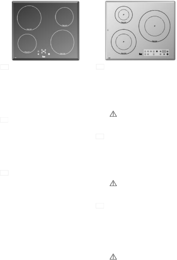
Model IR 604
12300 W induction hotplate
21400 W induction hotplate
31400 W induction hotplate
42300 W induction hotplate
* Induction power with the Power function enabled.
- Residual heat indicator (H)
- Maximum induction power: 7400 watts.
- Supply power: 230 Volts.
- Frequency: 50 Hertz.
- Induction frequency: 20 to 60 kilohertz
Modell IR 604
1Induktions-Kochzone mit 2300 W
2Induktions-Kochzone mit 1400 W
3Induktions-Kochzone mit 1400 W
4Induktions-Kochzone mit 2300 W
* Induktionsleistung bei aktivierter Power-Funktion.
- Restwärme-Anzeige (H)
- Maximale Induktionsleistung: 7400 W
- Versorgungsspannung: 230 V
- Frequenz: 50 Hz.
- Induktionsfrequenz: 20 bis 60 Kilohertz.
Modèle IR 604
1Plaque à induction de 2300 W
2Plaque à induction de 1400 W.
3Plaque à induction de 1400 W
4Plaque à induction de 2300 W
* Puissance d'induction lorsque la fonction Power est
activée.
- Témoin de chaleur résiduelle (H)
- Puissance maximale d'induction: 7400 Watts.
- Tension d'alimentation: 230 Volts.
- Fréquence: 50 Hertz.
- Fréquence d'induction: 20 à 60 kilohertz.
Model IQ 640
11.400 / 1.800* W induction hotplate
22.400 / 3.200* W induction hotplate
32.300 / 3.200* W induction hotplate
* Induction power with the Power function enabled.
- Residual heat indicator (H)
- Maximum induction power: 6.900 watts.
- Supply power: 230 Volts.
- Frequency: 50/60 Hertz.
- Induction frequency: 20 to 60 kilohertz
The inside circle on the cooking area
represents the minimum base diameter of the
pan, which is recognised by the inductor under
normal conditions.
Modell IQ 640
1Induktions-Kochzone mit 1.400 / 1.800* W
2Induktions-Kochzone mit 2.400 / 3.200* W
3Induktions-Kochzone mit 2.300 / 3.200* W
* Induktionsleistung bei aktivierter Power-Funktion.
- Restwärme-Anzeige (H)
- Maximale Induktionsleistung: 6.900 W
- Versorgungsspannung: 230 V
- Frequenz: 50/60 Hz.
- Induktionsfrequenz: 20 bis 60 Kilohertz.
Der Innenkreis auf dem Kochfeld stellt
den Mindestdurchmesser des Kochgeschirrbo-
dens dar, der unter normalen Umständen vom
Induktor erkannt wird.
Modèle IQ 640
1 Plaque à induction de 1.400 / 1.800* W
2 Plaque à induction de 2.400 / 3.200* W
3 Plaque à induction de 2.300 / 3.200* W
* Puissance d'induction lorsque la fonction Power est
activée.
- Témoin de chaleur résiduelle (H)
- Puissance maximale d'induction: 6.900 Watts.
- Tension d'alimentation: 230 Volts.
- Fréquence: 50/60 Hertz.
- Fréquence d'induction: 20 à 60 kilohertz.
Le cercle intérieur de la zone de cuisson
représente le diamètre minimal du fond du réci-
pient que reconnaît l'inducteur dans des condi-
tions normales d'utilisation.
GB
DE
FR
GB
DE
FR
1
2
3
8
GB
12
34
GB
DE
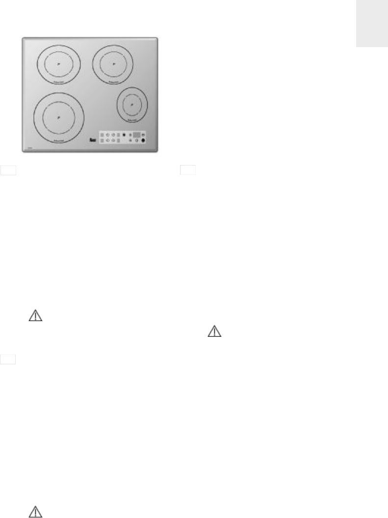
Model IQ 644
11.850 / 2.500* W induction hotplate
21.850 / 2.500* W induction hotplate
32.300 / 3.200* W induction hotplate
41.400 / 1.800* W induction hotplate
* Induction power with the Power function enabled.
- Residual heat indicator (H)
- Maximum induction power: 7.400 watts.
- Supply power: 230 Volts.
- Frequency: 50/60 Hertz.
- Induction frequency: 20 to 60 kilohertz
Induction elements 1 and 3 use the same induction
generator, which has a maximum power of 3,700 W.
Therefore, these two cooking zones cannot be used
at maximum power at the same time.
The inside circle on the cooking area
represents the minimum base diameter of the
pan, which is recognised by the inductor under
normal conditions.
Modell IQ 644
1Induktions-Kochzone mit 1.850 / 2.500* W
2Induktions-Kochzone mit 1.850 / 2.500* W
3Induktions-Kochzone mit 2.300 / 3.200* W
4Induktions-Kochzone mit 1.400 / 1.800* W
* Induktionsleistung bei aktivierter Power-Funktion.
- Restwärme-Anzeige (H)
- Maximale Induktionsleistung: 7.400 W
- Versorgungsspannung: 230 V
- Frequenz: 50/60 Hz.
- Induktionsfrequenz: 20 bis 60 Kilohertz.
Die Kochfelder 1 und 3 verfügen über einen
gemeinsamen Induktionsgenerator, der mit einer
Leistung von max. 3.700 Watt arbeitet. Daher kön-
nen diese beiden Kochfelder nicht gleichzeitig bei
maximaler Leistung betrieben werden.
Der Innenkreis auf dem Kochfeld stellt
den Mindestdurchmesser des Kochgeschirrbo-
dens dar, der unter normalen Umständen vom
Induktor erkannt wird.
Modèle IQ 644
1 Plaque à induction de 1.850 / 2.500* W
2 Plaque à induction de 1.850 / 2.500* W
3 Plaque à induction de 2.300 / 3.200* W
4 Plaque à induction de 1.400 / 1.800* W
* Puissance d'induction lorsque la fonction Power
est activée.
- Témoin de chaleur résiduelle (H)
- Puissance maximale d'induction: 7.400 Watts.
- Tension d'alimentation: 230 Volts.
- Fréquence: 50/60 Hertz.
- Fréquence d'induction: 20 à 60 kilohertz.
Les plaques 1 et 3 comportent le même générateur
à induction, qui dispose d'une puissance maximale
de 3700 W. C'est pourquoi, ces deux zones de cuis-
son ne pourront être utilisées simultanément à la
puissance maximale.
Le cercle intérieur de la zone de cuisson
représente le diamètre minimal du fond du réci-
pient que reconnaît l'inducteur dans des condi-
tions normales d'utilisation.
FR

GB
10
Guide to Using the Instructions Booklet
Dear customer,
We are delighted that you have put your
trust in us.
We are confident that the new hob that you
have purchased will fully satisfy your
needs.
This modern, functional and practical
model has been manufactured using top-
quality materials that have undergone
strict quality controls throughout the manu-
facturing process.
Before installing and using it, we would
ask that you read this Manual carefully and
follow the instructions closely, as this will
guarantee better results when using the
appliance.
Keep this Instruction Manual in a safe
place so that you can refer to it easily and
thus abide by the guarantee conditions.
In order to benefit from this Guarantee, it is
essential that you submit the purchase
receipt together with the Guarantee Certi-
ficate.
You should keep the Guarantee
Certificate or, where relevant, the tech-
nical datasheet, together with the Ins-
truction Manual for the duration of the
useful life of the appliance. It has
important technical information about
the appliance.
Safety instructions
Before first use, you should carefully read
the installation and connection instruc-
tions.
These hob models may be installed in the
same kitchen furniture units as TEKA
brand ovens.
For your safety, installation should be
carried out by an authorised technician
and should comply with existing installa-
tion standards. Likewise, any internal work
on the hob should only be done by TEKA’s
technical staff, including the change of the
flexible supply cable of the appliance.
Please note:
When the hotplates are in opera-
tion or have recently been in operation,
some areas will be hot and can burn.
Children should be kept well away.
If the glass ceramic breaks or
cracks, the hob should immediately be
disconnected from the electric current
in order to avoid the risk of electric
shock.
Do not leave anything on the
hob’s cooking areas while it is not in
use. Avoid risk of fire.
Do not place metal objects, such
as knives, forks, spoons or lids on the
surface of the hob, as they may get very
hot.
GB
11
INSTALLATION AND SETUP SHOULD
BE CARRIED OUT BY AN AUTHORISED
TECHNICIAN IN LINE WITH CURRENT
INSTALLATION STANDARDS.
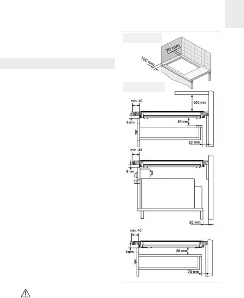
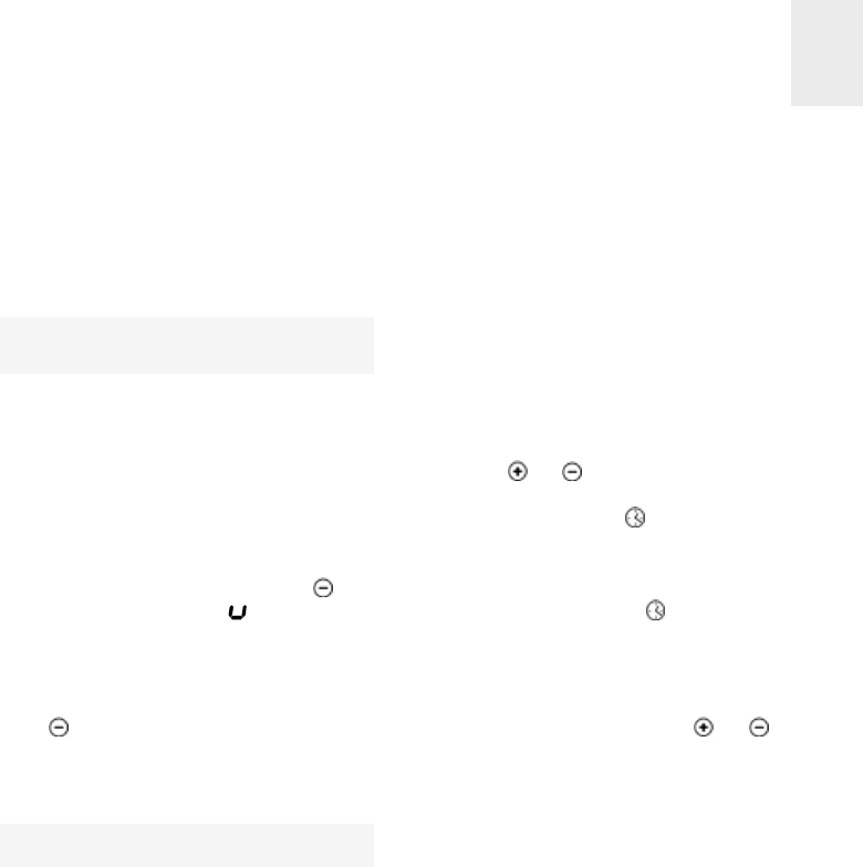
Positioning the hob
To install these models, an opening with
the dimensions shown in figure 2 will be
cut into the unit’s worktop.
The minimum distance between the surfa-
ce supporting the cooking pans and the
lower part of the kitchen unit or the hood
located above the hob should be 650 mm.
If the hood’s installation instructions
recommend that the gap is greater than
this, you should follow this advice.
The unit where the hob and oven will be
located will be suitably fixed.
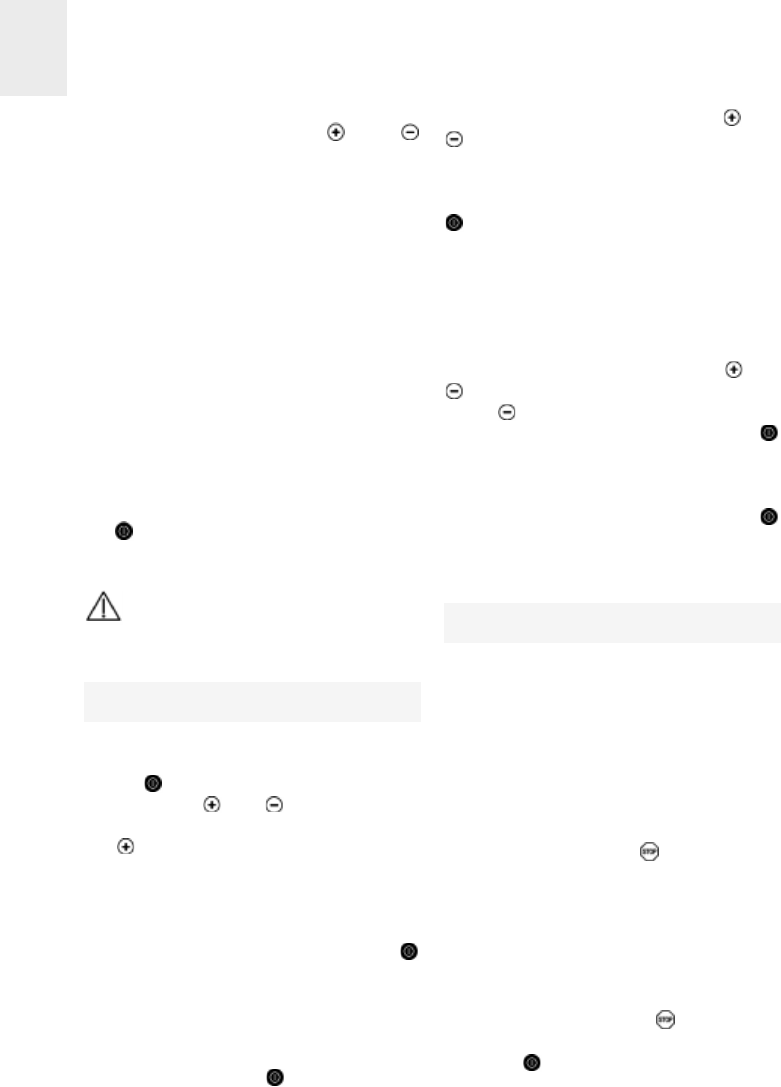
INSTALLATION WITH CUTLERY DRA-
WER OR LOWER CABINET
In mixed induction - vitroceramic hobs, if
you would like to have a cabinet or a
cutlery drawer under the hob, it is neces-
sary to put a separation board in between
the two. The board should be situated 20
mm below the underside of the hob, lea-
ving a free space of at least 20 mm until
the end of the cabinet (figure 1).
This prevents accidental contact with the
hot surface of the casing of the heating
elements under the apparatus (figure 1).
In induction hobs, there should be a mini-
mum distance of 5 cm between the drawer
and the opening to the fan (a separating
board is not necessary).
Please do not store objects that
can obstruct the hob fans or possibly
flammable materials in the drawer.
INSTALLATION WITH FAN OVEN
UNDER THE HOB
The oven should be installed according to
the corresponding manual.
Installation
fig. 1
DRAWER
Minimum distance
to wall
Minimum ventilation
distances
OVEN
Mixed hobs:
DRAWER

If a fan oven is being installed, please
remember that this hob has only been cer-
tified to work with TEKA brand ovens.
Leave a space in the front of the cabinet so
that the hot air can ventilate properly. The
opening should be at least 5 mm high. The
longitude should be the width of the cabinet.
An opening of 20 mm should be made in
the back part of the cabinet in order to
allow cold air to enter (see figure 1).
INSTALLING THE AIR NOZZLE
(MODELS …604)
Place the nozzle over the air vent with the
air valve toward the front part of the hob
and use the screws provided to screw the
nozzle. By doing so, the air nozzle will stay
braced to the back of the hob.
Warnings:
When hobs are handled before
being installed, care should be taken in
case there is any protruding part or
sharp edge which could cause injury.
When installing units or applian-
ces above the hob, the hob should be
protected by a board so that the glass
cannot be damaged by accidental
blows or heavy weights.
The glues used in manufacturing
the kitchen unit and in the adhesive on
the decorative laminate of the worktop
surface should be made to tolerate tem-
peratures of up to 100ºC.
TEKA assumes no responsibility
for any malfunction or damage caused
by faulty installation.
PLEASE REMEMBER THAT THE GUA-
RANTEE DOES NOT COVER THE
GLASS IF IT SUFFERS A VIOLENT
BLOW OR IF IT IS USED IMPROPERLY.
Fastening the hob
When the gap has been properly sized, the
sealing washer should be put on the lower
face of the glass. Silicone should not be
applied between the glass and the unit
GB
12
fig. 3
fig. 2
Model ...604:
575 max.
W
L
The dimensions L and W are shown in the table
"Dimensions and characteristics" of the Technical
Information section.
Fitting holes
W
L
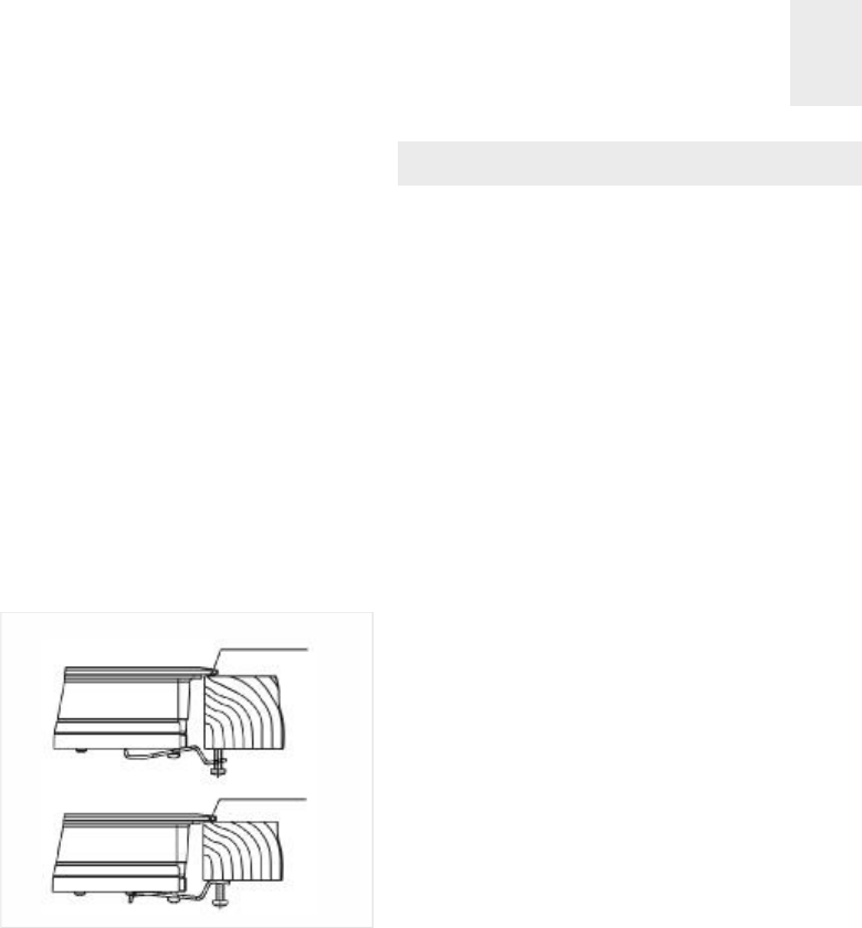
worktop because if it becomes neces-
sary to remove the hob from its position,
the glass could break when trying to
detach it.
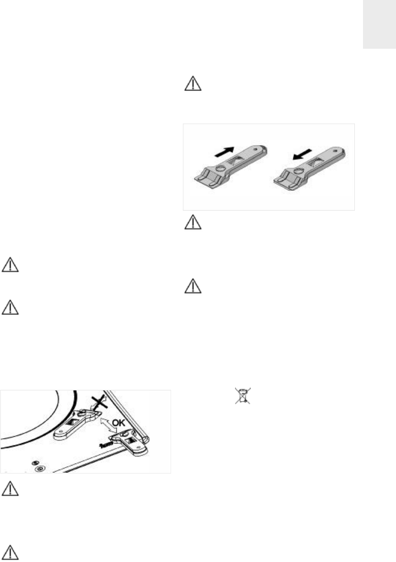
To secure the hob to the cabinet, four brac-
kets should be fastened to the existing holes
on the bottom part of the casing (two in the
front and two in the back). There are two
possibilities of where the brackets may be
placed, just as is shown in figure 4.
Depending on the thickness of the cabinet, it
may be necessary to use the self tapping
screws (M5) that are provided as compli-
ments for securing; insert them in the circu-
lar holes of the bracket. The thread of this
hole will be made when the screw is inser-
ted inside of it. The thread should be made
before fastening the bracket to the hob.
Connecting the electricity
The electric connection is made via an
omnipolar switch or plug where accessible,
which is suitable for the intensity to be tole-
rated and which has a minimum gap of 3
mm between its contacts, which will ensure
disconnection in case of emergency or
when cleaning the hob.
The connection should include correct eart-
hing, in compliance with current norms.
If the flexible supply cable fitted to these
appliances ever needs to be changed, it
should be replaced by TEKA’s official service.
The input cable should not be in contact
either with the body of the hob or with the
body of the oven, if the oven is installed in
the same unit.
GB
13
fig. 4 Sealing washer
Sealing washer

GB
Technical details
The supply voltage and frequency will be
as shown on the rating plate.
Class 3 hob.
Technical Information
* Induction power with the Power function enabled.
** Model IR 604 has a length of 600 mm.
SEE THE APPLIANCE’S RATING PLATE
Dimensions and characteristics
55
600
510
560
490
50
55
600
510
560
490
50
IR 622
IT 622
56
600
510
560
490
52
1
1
1
1
1
1
50-6050-60
50-60
7.2006.8007.300
IR 635
IT 635 IR 645
IT 645
55
700
510
560
490
50
1
1
50-60
6.800
IR 735 AB IQ 644 IQ 640
55
600
510
560
490
50
55
600
510
560
490
50
50-60 50-60
7.400 6.900
1
1
1
1
11
11
2
2
50
68
590**
510
570
492
64
7.400
IR 604
2
2
1
Model
Hob dimensions
Height (mm)
Length (mm)
Width (mm)
Dimensions of the placement in the unit
Length (mm)
(L)
Width (mm)
(W)
Depth (mm)
Configuration
Double radiant hotplate
700/2.100 W
Radiant hotplate 1.5
00W
Induction hotplate
2.400 / 3.200*
W
Induction hotplate
1.400 /1.800* W
Inducción hotplate
2.300 / 3.200* W
Induction hotplate
1.850 / 2.500* W
Induction hotplate
2.200 / 3.200* W
Induction hotplate
1.800 / 2.500* W
Induction hotplate
1.400 W
Induction hotplate
2.300 W
Electrics
Nominal Power
(W) for 230 V
Supply
voltage (V)
Frequency (Hz)
Before starting for the
first time
Before connecting the hob to the electrical
network, verify that the tension (voltage)
and the frequency of the hob correspond
to the voltage and frequency indicated on
the hob rating plate, which is located on
the underside of the hob and in the gua-
rantee or, if applicable, on the technical
data sheet that should be kept with this
manual during the useful life of the appa-
ratus.
The apparatus is not designed to
be used by people (including children)
with reduced physical, mental or sen-
sory abilities. It should also not be used
by people that do not have experience
handling the apparatus or who do not
have knowledge of the apparatus,
unless they are supervised by a person
who is in charge of their safety.
Children should not be allowed
to play with the apparatus.
Touch control user instruc-
tions (models ...622, ...635,
...645, ...735 AB and ...604)
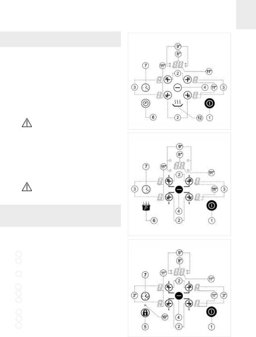
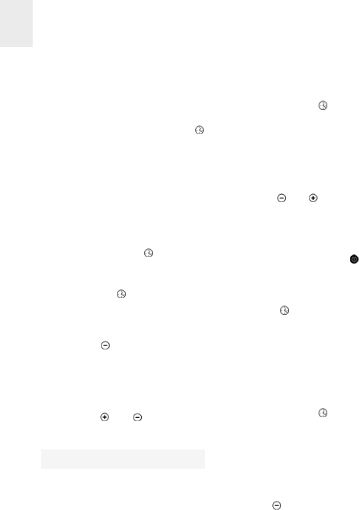
CONTROL PANEL ELEMENTS (see figs.
5, 6 and 7)
On/off sensor.
Hotplate selection sensors and increase
power sensor (more).
Power and/or residual heat displays.
Also shows that locking is enabled.
Reduce power/time sensor (less).
Sensor lock (model …604).
Operating sensor "Power" (models
…635, …645, …735 AB and …622).
Time setting/increase sensor.
Indicator of selected time (clock).
Indicator light of the induction element
with timer.
GB
15
Use and Maintenance
1
2
3
4
5
6
7
8
9
fig. 5
Models ...622
Models ...635, ...645 and ...735 AB
fig. 6
Models ...604 fig. 7
Lock activated indicator light (model
…604).
Decimal point in power indicators and
time indicator.
- Shines (on): Chosen induction element
(ready to be used).
- Doesn't shine (off): Induction element
locked (cannot be used).
Keep warm sensor (models …622).
N.B.: * Only visible when in operation.
The sensors marked on the control panel
are used for control purposes.
There is no need to exert pressure on the
glass - you enable the function you requi-
re simply by touching the sensor with your
finger.
Each action is confirmed by a beep.
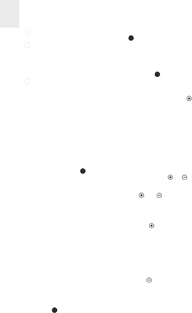
SWITCHING THE APPLIANCE ON
1Touch the On sensor (1) for at least
one second.
The touch control is enabled, 0appears on
all the power displays (3) and the decimal
point (11) flashes on and off to indicate
that no cooking area is selected at that
time. If the cooking area is hot, the corres-
ponding display will alternate between a H
and an 0.
If the safety lock function is enabled, the
cooking area displays will show the letter
L. If the cooking area is still emitting resi-
dual heat, the corresponding display will
alternate between the letters Land H.
The following action must be carried out
within 20 seconds or the touch control will
automatically switch off.
When the touch control is enabled, it can
be disconnected at any time by touching
the sensor (1), even if the lock is on
(safety lock function enabled). The sensor
(1) always has priority for disconnec-
ting touch control.
SWITCHING THE HOTPLATES ON
Once the touch control has been enabled
using the sensor (1), the hotplates
required can be switched on.
1Select the hotplate by touching the
corresponding sensor (2). N.B.: the
sensor has a double function: the first
press selects the hotplate and the follo-
wing presses increase the power.
A 0appears on the corresponding power
display and the decimal point (11) lights up
to show that the hotplate is selected.
Before using a hotplate, first check that
it is selected, i.e. that the correspon-
ding decimal point (11) is showing.
2Using sensors or (2/4), select the
required power level (from 1to 9).
The and sensors are repetitive, so if
you keep your finger on them they go up or
down continuously.
After 10 seconds have elapsed from the last
time the key was pressed, the decimal
point goes out and the hotplate is locked.
Only one hotplate can be enabled at a
time, which means that only one decimal
point (11) will be lit up.
To turn a hotplate up to full power
quickly: Select the hotplate and touch the
sensor (4) once. The hotplate will be
set to its maximum power (level 9).
SWITCHING THE HOTPLATE OFF
1The hotplate must have already been
GB
16
11
12
10
selected. The corresponding decimal
point (11) must be lit.
2Use sensor (4) to decrease the power
to level 0. The hotplate will automatically
switch off.
To turn it off quickly: Whatever the
power level, the hotplate is turned off
immediately if you touch the and
sensors (2/4) simultaneously.
If all the cooking areas are positioned at 0,
all the display points will flash.
When a hotplate is switched off, an Hwill
appear on the corresponding power dis-
play if the surface of the glass in the
corresponding cooking area reaches a
temperature at which there is a risk of bur-
ning. When the temperature drops, the
display will go out (if the hob is disconnec-
ted), or a 0is displayed if the hob is still on.
SWITCHING THE APPLIANCE OFF
The appliance may be switched off at any
time by touching the general on / off sen-
sor (1). When in standby mode, an His
displayed on any hot areas. None of the
other hotplate displays will light up.
After use, disconnect the device
using the control; do not rely on the
cookware detector.
Locking the hob sensors
SAFETY FUNCTION
(models ...635, ...645, ...735 AB and ...622)
The safety function can be enabled after
the hob is connected. To do so, touch sen-
sor (1) to enable the touch control.
Immediately, touch the sensor (4) and
hold it down for five seconds. An L(for
'Locked') will appear on the displays. The
touch control will be switched off after a
few seconds. If the cooking area is hot, an
Land an Hwill appear alternately on the
corresponding display.
This operation needs to be done within 10
seconds, with no sensor other than those
indicated being touched during that time,
or the locking will not be carried out.
The electronic control will remain locked
until the user unlocks it, even after the con-
trol is disconnected using the sensor
(1) or when restarting after there has been
a power cut.
Unlocking in order to cook
To unlock the control and use it, touch sen-
sor (1) to enable the touch control.
Immediately touch the two sensors on
the right at the same time. The Lvanishes
from the displays and a 0appears with the
lower point flashing, or an Hif the corres-
ponding hotplate is hot, and the hob will be
ready to use for cooking. When you switch
off the control using the on/off sensor
(1) the safety function will be re-enabled
and will reappear the next time the touch
control is enabled.
Cancelling the safety function
The safety function can be permanently
disabled by pressing sensor for 5
seconds immediately after enabling the
touch control. This should be done within
10 seconds after enabling the touch con-
trol using the on/off sensor (1), and the
safety function will be cancelled. If this is
not done properly, the touch control will
remain locked and will switch off after 20
seconds.
After cancelling the safety function, when
the control is re-enabled using the on/off
sensor (1), the hob will be ready to be
GB
17
used for cooking.
LOCK FUNCTION
(models ...604)
Using the sensor lock (5) you can lock
the entire unit, except the on/off sensor
key (1), in order to protect the unit from
unwanted use. This is a useful safety func-
tion when there are children in the home.
When the lock is activated, the light (10)
goes on.
If you turn off the device using the on/off
sensor key (1) at the same time that the
lock is activated, the device will continue to
be locked the next time it is turned on.
Function for keeping a pan hot
(models …622)
Using this function, it is possible to keep
food hot in a pan placed on the cooking
area.
1There is a pan on one of the heating ele-
ments at a previously selected cooking
temperature.
2It is necessary to touch sensor (12),
after which the symbol will appear in
the indicator.
To disconnect this function, just touch sen-
sor (12) again and the heating element
will turn off, or, as an alternative, it is pos-
sible to touch sensor (2) and change to
level 1. This function will only work for a
maximum of 120 minutes, after which the
hob will disconnect.
Timer function
This feature enables you to do your coo-
king while you are not present: You can set
the timer for a hotplate and it will switch
itself off automatically when this time has
elapsed.
Around the selected time display there are
4 or 3 pilot lights that indicate which hotpla-
te is being timed. For example, if you time
the upper left hotplate as you look at the
appliance, the pilot light that will come will
be the one above the display and to the left.
Where no hotplate is being timed (no pilot
light (9) is on), the clock can be used as a
countdown timer (see the section "The
clock as a countdown timer").
You can use the clock as a countdown
timer for periods of between 1 and 99
minutes, and as a hotplate timer for times
of between 1 and 99 minutes. All the coo-
king areas can be programmed indepen-
dently and simultaneously.
Timing a hotplate
1The hotplate to be timed has to be selec-
ted. The corresponding decimal point
(11) must be lit.
2Select a power level of between 1and 9
using the or sensors (2/4).
3Touch the clock sensor (7). The deci-
mal point (11) of the time display (8)
(which shows 00) will come on, and it
will flash on and off along together with
the pilot light (9) of the corresponding
hotplate.
4Touch the clock sensor (7) again to
increase the value of the time you wish
to set, or (4) to decrease it (from 1 to
99 minutes). You can keep your finger
on the or sensors (7/4) to make
the minutes pass by automatically and
make your selection more quickly.
The clock will begin to control the time
automatically. The control display (8)
GB
18
corresponding to the timed area will
remain lit up.
When the chosen time elapses, the timed
area will switch off and the clock will give a
series of beeps for several seconds. The
time display will show 00and this will flash
on and off, together with the pilot light of
the hotplate that has disconnected.
If the hotplate that has been switched off is
hot, its display will show an H, otherwise it
will show a 0. Touch any sensor to switch
off the beeping signal.
When more than one hotplate is being
timed simultaneously, the time display will
show the cooking time remaining in the
hotplate to disconnect first by default. If
you wish to check the cooking time remai-
ning in another hotplate, touch its selection
sensor. For a few seconds the display will
show the remaining cooking time for that
hotplate.
Changing the programmed time
The time that you have set can be chan-
ged later on if you so wish.
1The hotplate being timed must have alre-
ady been selected. The corresponding
decimal point (11) must be lit.
2Touch the clock sensor (7). The deci-
mal point (11) will come on.
3Use the or sensors (7/4) to alter
the time.
Disconnecting the clock
If you wish to stop the clock before the pro-
grammed time has elapsed:
1The hotplate being timed must have alre-
ady been selected. The corresponding
decimal point (11) must be lit.
2Select the clock sensor (7). The deci-
mal point (11) will come on.
3Use sensor (4) to reduce the time
down to 00. The clock is cancelled but
the hotplate will remain enabled until
you switch it off.
Switching off quickly
1The hotplate being timed must have alre-
ady been selected. The corresponding
decimal point (11) must be lit.
2Select the countdown timer sensor
(7). The corresponding decimal point
(11) must be lit.
3Touching the and sensors (7 and
4) at the same time cancels the remai-
ning time.
You can also switch the hotplate being
timed off without the programmed time
having elapsed. In this case, the timer will
switch off too.
The clock as a countdown timer
Whenever the clock is not being used in
conjunction with a cooking area, it can be
used as a countdown timer. To do this, you
use the clock without selecting a hotplate.
SWITCHING THE COUNTDOWN TIMER
ON
When the appliance is switched off.
1Touch the On sensor (1).
GB
19

2Before using any hotplate, touch the
clock sensor (7). All the control dis-
plays (9) are switched off.
3Use the sensors or (7/4) to input
the time you want.
When the programmed time elapses, a
series of beeps will sound for several
seconds. To switch these beeps off, touch
the sensor (7).
DISCONNECTING THE COUNTDOWN
TIMER
If you wish to stop the countdown timer
before the programmed time has elapsed:
1Select the countdown timer sensor
(7). The decimal point (11) will come on.
2Use sensor (4) to reduce the time to
00. The clock is cancelled.
SWITCHING OFF QUICKLY
1Select the countdown timer sensor
(7). The decimal point (11) will come on.
2Touch sensors or (7/4) simulta-
neously to disconnect the countdown
timer.
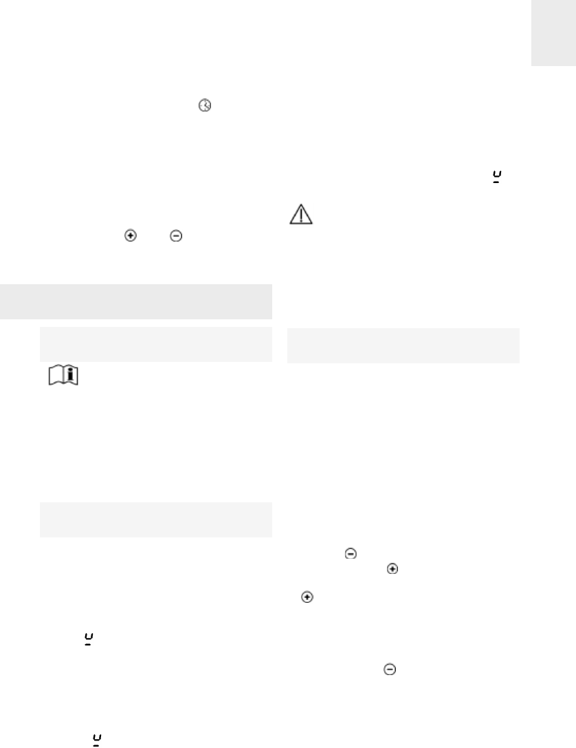
Touch control user instruc-
tions (models ...640 and ...644)
CONTROL PANEL ELEMENTS (see fig.
8)
On/Off button.
Hob selection buttons.
Power and/or residual heat, and lock
activation displays.
Reduce power/time button (reduce).
Increase power/time button
Power button.
Timer/countdown timer selection button
Timer display (timer).
Stop button.
Hob timer light.
Decimal point in the power and timer
displays.
- Shines (on): Chosen induction element
(ready to be used).
- Doesn't shine (off): Induction element
locked (cannot be used).
Countdown timer indicator.
N.B.: * Only visible when in operation.
The sensors marked on the control panel
are used for control purposes.
There is no need to exert pressure on the
GB
20
Models ...640 and ...644
fig. 8
1
2
3
4
5
6
7
11
10
9
8
13
glass - you enable the function you requi-
re simply by touching the sensor with your
finger.
Each action is confirmed by a beep.
SWITCHING THE APPLIANCE ON
1Touch the On sensor (1) for at least
one second.
The touch control is enabled, 0appears on
all the power displays (3) and the decimal
point (11) flashes on and off to indicate
that no cooking area is selected at that
time. If the cooking area is hot, the corres-
ponding display will show Hinstead of 0.
If the safety lock function is enabled, the
cooking area displays will show the letter
L. If the cooking area is still emitting resi-
dual heat, the corresponding display will
alternate between the letters Land H.
The following action must be carried out
within 10 seconds or the touch control will
automatically switch off.
When the touch control is enabled, it can
be disconnected at any time by touching
the sensor (1), even if the lock is on
(safety lock function enabled). The sensor
(1) always has priority for disconnec-
ting touch control.
SWITCHING THE HOTPLATES ON
Once the touch control has been enabled
using the sensor (1), the hotplates
required can be switched on.
1Select the hotplate by touching the
corresponding sensor (2).
A 0appears on the corresponding power
display and the decimal point (11) lights up
to show that the hotplate is selected.
Before using a hotplate, first check that
it is selected, i.e. that the correspon-
ding decimal point (11) is showing.
2Using sensors or (5/4), select the
required power level (from 1to 9).
The and sensors are repetitive, so if
you keep your finger on them they go up or
down continuously.
After 10 seconds have passed since pres-
sing the corresponding hob selection but-
ton (2), the decimal point goes out and the
hob is locked.
Only one hotplate can be enabled at a
time, which means that only one decimal
point (11) will be lit up.
To turn a hotplate up to full power
quickly: Select the hotplate and touch the
sensor (4) once. The hotplate will be
set to its maximum power (level 9).
If all the cooking areas are positioned at 0,
all the display points will flash.
When a hotplate is switched off, an Hwill
appear on the corresponding power dis-
play if the surface of the glass in the
corresponding cooking area reaches a
temperature at which there is a risk of bur-
ning. When the temperature drops, the
display will go out (if the hob is disconnec-
ted), or a 0is displayed if the hob is still on.
SWITCHING THE HOTPLATES OFF
1The hotplate must be selected before-
hand. The corresponding decimal point
(11) must be lit.
2Use sensor (4) to reduce the power
to 0. The hotplate will turn off automati-
cally.
GB
21
To turn it off quickly: Whatever the
power level, touch sensors and
(2/4) simultaneously and the hob will be
instantly switched off.
If all the hobs are at 0, all the points on the
display will flash.
When turning off a hob, an Hwill be dis-
played on the corresponding power dis-
play if the hob's glass is at a high tempe-
rature, which can cause burning, . When
the temperature has reduced, the display
turns off (if the stove is switched off). If the
stove is still on then a 0is displayed.
SWITCHING THE APPLIANCE OFF
The appliance may be switched off at any
time by touching the general on / off sen-
sor (1). When in standby mode, an His
displayed on any hot areas. None of the
other hotplate displays will light up.
After use, disconnect the device
using the control; do not rely on the
cookware detector.
Locking the hob sensors
The safety function can be activated once
the stove is switched on. To do this, touch
sensor (1) to activate the touch control.
Touch buttons and (2/4) simultane-
ously, followed by the power increase but-
ton (5). An L will appear on the power
displays (3), indicating that the touch con-
trol is locked.
The electronic control will remain locked,
even after switching it off using sensor
(1), until it is unlocked by the user.
Unlock for Cooking
If you wish to unlock the touch control for
cooking, touch sensor (1) to activate it.
Immediately after, touch sensors and
(5/4) simultaneously. The Lwill no lon-
ger be displayed and the touch control will
operate normally. When the touch control
is switched off using the On/Off sensors
(1), the safety function will be reactiva-
ted and the Lwill be displayed the next
time the touch control is turned on.
Turning Off the Safety Function
The safety function can be deactivated
permanently, by touching sensors and
(5/4) at the same time, followed by sen-
sor (4), after having switched on the
touch control using the On/Off sensor
(1).
After this, when the touch control is turned
on again by using the On/Off sensor
(1), the hob will be ready to be used. If the
touch control is locked in the event of a
power cut, it will be deactivated.
STOP Function
This function allows you to pause the coo-
king process. If the timer is activated, this
will also be paused.
Activating the Stop Function
1The pans are on the hobs, which are set
at a specific level
2Touch the Stop sensor (9). The power
displays (3) will scroll through the letters
S-T-O-P instead of showing the selected
cooking level. Cooking will remain pau-
sed.
Deactivating the Stop Function
1Touch the Stop sensor (9) followed
by any other button except the On/Off
sensor (1). Cooking will be resumed
GB
22
with the same settings (power levels,
cooking time) as before the pause.
The second button must be pressed within
10 seconds, otherwise the stove will
switch off. If cooking is not resumed within
10 minutes of being paused, the stove will
again switch off.
Function for keeping a pan hot
(models …622)
Using this function, it is possible to keep
food hot in a pan placed on the cooking
area.
1There is a pan on one of the heating ele-
ments at a previously selected cooking
temperature.
2It is necessary to touch sensor (4),
after which the symbol will appear in
the indicator. This is a level between the
0and 1.
To disconnect this function, just touch sen-
sor (4) and change to level 0. This
function will only work for a maximum of
120 minutes, after which the hob will dis-
connect.
Timer function
This function aids the cooking process, as
it is not necessary to be watching: You can
set a hob timer and it will turn off automa-
tically once the selected time has elapsed.
There are 4 lights surrounding the timer
display, showing which of the hobs has a
timer set. For example, if you set a timer
for the upper left hob, the light on the
upper left of the timer display will turn on.
If there are no timers set on any of the
hobs (no hob timer light (10) on), the timer
can be used as a countdown timer (see
section "Countdown Timer").
On these models you can set the count-
down timer and the hob timer from 1 to 99
minutes. All of the hobs can be program-
med independently and operate simulta-
neously.
Timing a hotplate
1The hotplate to be timed has to be selec-
ted. The corresponding decimal point
(11) must be lit.
2Select a power level of between 1and 9
using the or sensors (5/4).
3Touch the clock sensor (7). The deci-
mal point (11) of the time display (8) will
come on
4Touch the clock sensor sensor (7)
until the time display of the correspon-
ding hotplate (10) flash on.
5Now set a cooking time, between 1and
99 minutes, using the sensors or
(5/4). With the first one you will start with
1, and with the second with 30. Touching
both at the same time the value will
come back to 00.
The clock will begin to control the time
automatically. The control display (10)
corresponding to the timed area will
remain lit up. If you want to set a time for
another hotplate, you have to repeat the 4
and 5 steps.
When the chosen time elapses, the timed
area will switch off and the clock will give a
series of beeps for several seconds. The
time display will show 00and this will flash
on and off, together with the pilot light of
the hotplate that has disconnected.
If the hotplate that has been switched off is
GB
23
hot, its display will show an H, otherwise it
will show a 0. Touch any sensor to switch
off the beeping signal.
Changing the programmed time
The time that you have set can be chan-
ged. To do so, touch the clock sensor
(7) until the display of the corresponding
hotplate (10) flash on.
Then you will be able to read and change
te time.
Disconnecting the clock
If you wish to stop the clock before the pro-
grammed time has elapsed:
1Touch the clock sensor (7) so many
times as it's needed, until the display of
the corresponding hotplate (10) flash
on, or just select the hotplate and touch
the clock sensor (7).
2Make sure the decimal point is light (11)
in the indicator (8).
3Use sensor (4) to reduce the time
down to 00. The clock is cancelled.
Switching off quickly
Repeat the steps1 and 2.
3Touching the and sensors (5 and
4) at the same time cancels the remai-
ning time.
The clock as a countdown timer
Whenever the clock is not being used in
conjunction with a cooking area, it can be
used as a countdown timer.
SWITCHING THE COUNTDOWN TIMER
ON
When the appliance is switched off.
1Touch the timer button (7) as many
times as necessary, until the correspon-
ding countdown timer light (13), located
in the centre, below the timer displays
(8), turns on.
2Make sure the decimal point is light (11)
in the indicator (8).
3Use sensors and (4/5) to set the
time.
After the set time has elapsed, a series of
beeps will be emitted for several seconds.
To turn off these beeps touch any of the
buttons, except the On/Off button (1).
Adjusting the Programmed Time
To adjust the programmed time, hold down
the timer button (7) until the countdown
timer light (13) flashes. You can then see
the time and adjust it.
DISCONNECTING THE COUNTDOWN
TIMER
If you wish to stop the countdown timer
before the programmed time has elapsed:
1Touch the timer button (7) as many
times as necessary, until the correspon-
ding countdown timer light (13) turns on,
located centrally, below the timer dis-
plays (8).
2Make sure the decimal point is light (11)
in the indicator (8).
3Use sensor (4) to reduce the time to
00. The clock is cancelled.
GB
24
SWITCHING OFF QUICKLY
1Touch the clock sensor (7) many
times as necessary, until the correspon-
ding countdown timer light (13) turns on,
located centrally, below the timer dis-
plays (8).
2Make sure the decimal point is light (11)
in the indicator (8).
3Touching the and sensors (5 and
4) at the same time the countdown timer
will switch off..
Touch control user instruc-
tions for all the models
Power supplied according to
the power level selected
Bear in mind that induction areas
adjust the amount of power supplied
according to the size and type (material) of
pan placed on them. A smaller pan will
receive less power than a larger one.
Thus, depending on the pan being used,
the power supplied may vary from the
values shown in Table 1.
Detecting pans
(Induction hotplates)
The induction cooking areas have a built-
in pan detector. This prevents the hotplate
from being left on with no pan on the sur-
face or when the pan is not suitable.
The power display will show the "no pan"
symbol if, when the area is switched on,
it detects that there is no pan or that the
pan is unsuitable.
If a pan is removed from the area while it
is operating, the hotplate will automatically
switch off and the "no pan" symbol will
come on . When the pan is placed back
on the cooking area, it will switch back on
at the power level previously selected.
Pan detection time is 10 minutes. If this
time elapses without a pan or a suitable
pan being put in position, the cooking area
will switch itself off. The power level will go
from showing the "no pan" symbol to
showing 0.
After use, switch the cooking area
off using the touch controls. If not pro-
perly switched off, an undesired use
may be given to the cooking area if a
pan were to be placed inadvertently on
the same area within the following ten
minutes. Avoid possible accidents!
Heat-up
(Starting cooking automatically)
This feature enables you to set the start
time for cooking. The touch control pre-
programs the selected hotplate to maxi-
mum power and then, after a certain time,
reduces it to the power level that you have
selected. (See table 2).
SWITCHING HEAT-UP ON
1Enable the required hotplate using the
corresponding sensor (2).
2Use the sensor to select power 9 and
then touch the sensor. An Awill be
shown on the display for as long as the
sensor is held down. When you stop
pressing, the power display will alterna-
te between Aand 9.
For the 15 seconds after enabling remote
cooking, use the sensor to drop to the
continuous cooking power level that you
want (for example, 6). The display light will
flash on and off, alternating between 6and A.
GB
25
Example:
You want to cook at power level 6on an
induction cooking area and begin with
rapid heating.
Select power 9, touch the sensor again
and Awill come on, and then come down
to power level 6using the sensor. The
system keeps the hotplate at power 9
(maximum) for 460 or 120 seconds
(depending on the model), flashing alter-
nately between 6and A, after which time
the cooking level continues at 6automati-
cally.
MODIFYING THE POWER LEVEL
DURING HEAT-UP
1The selected hotplate must have already
been enabled. The corresponding deci-
mal point must be lit (11).
2Use the sensor (2, or 5 in models
...640 and ...644) to change the power
level.
When increasing the power using the
sensor (2, or 5 in models ...640 and
...644) the time that has already elapsed is
taken into account.
Example:
You are cooking and you have chosen
level 1 power (48 seconds burst of coo-
king) and after 30 seconds change it to 4
(312 seconds). The remaining time of the
bust of cooking will be 282 seconds (312
minus 30).
Heat-up time will be discontinued on
induction hotplates if the pan is remo-
ved. If a pan is put back within the pan
detection time (10 minutes) the heat-up
time that remained will recommence.
With induction hotplates, heat-up cannot
be enabled if the Power function is ena-
bled.
SWITCHING HEAT-UP FUNCTION OFF
When at least 10 seconds have elapsed
since heat-up function was enabled:
1Select the hotplate. The decimal point
(11) is lit.
2Touch the sensor (4).
The heat-up function is automatically disa-
bled and the hotplate remains at the cons-
tant cooking level.
The Power function
(Concentrated power)
except ...604 model
Up to 3.200 watts can be concentrated in
the induction cooking areas using the
Power function (see values marked * in the
presentation section).
1Select the desired cooking area, the
decimal point (11) will come on.
2Next touch the Power sensor or
(6). The power level display will show
the symbol P.
The maximum duration of the Power func-
tion is 10 minutes. When this time elapses,
the power level will automatically adjust to
power level 9.
Each side of the hob has an induction
generator that works with a maximum
power or 3,600/3,700 watts. Therefore, the
Power function cannot be activated at the
same time in two heating elements that
are on the same side. In other words, if
this function is working on a heating ele-
ment on the left, the Power function can
GB
26

only be activated in another heating ele-
ment on the right.
Once this function has been activated in a
heating element, the heating element on
the same side will only be able to work
with the power that is left over, up to a total
of 3,600/3,700 watts. If the power level is
too high, the touch control will automati-
cally reduce it; this will be shown by the
flashing of the indicator of the correspon-
ding power (3).
The Power function can be switched off in
the following ways:
* By pressing the Power sensor or
(6) again after selecting the cooking
area.
* By touching the (4) key while the coo-
king area is selected.
The function may also disconnect automa-
tically if the temperature in the cooking
area gets too hot. In all of these cases, the
hotplate is kept running at power level 9. If
the pan is taken off the cooking area while
Power concentration is in operation, the
function's remaining time will be stopped.
If a pan is put back onto the cooking area
before the pan detection time (10 minutes)
has elapsed, the remaining time will start
to count down again.
The Power function can also be enabled
without a pan on the cooking area, but the
hotplate will not come on until the pan is
put on the cooking area.
The Power function takes priority over heat-
up, so if the "Power" function is being used,
heat-up will be cancelled in the induction
cooking areas on the corresponding side.
Disconnection for safety
purposes
MAXIMUM OPERATING TIME
If, due to absent-mindedness, one or more
hotplates are left on, these will be switched
off automatically after a set amount of time
from the last action. (See table 3).
After this "safety disconnection", the
corresponding hotplate's power display
will show the Hif there is a risk of burning.
Otherwise it will show the 0.
SAFETY AGAINST COVERING SENSORS
The touch control has a feature that auto-
matically disconnects the appliance when
it detects that something (a pan, cloth or
spilled liquid) is covering the panel's sen-
sors. This prevents the item from enabling
or disabling a hotplate without you being
aware of it.
When the touch control disconnects the
appliance for safety reasons, it will beep
until you remove the item that is covering
the control panel.
If the touch controls are on standby, items
placed over the hotplates will not be detec-
ted; however, in order to enable the con-
trol, any item covering it must be removed.
Overheating safety feature
The induction areas are protected against
overheating that may cause damage to the
electronic system.
The induction generator has three mecha-
nisms which become active if the tempera-
ture rises too high in order to protect the
electronic components.
GB
27

GB
* Function Power, only visible when in operation
Table 1
0
1
2
3
4
5
6
7
8
9
[P]*
Models ...635 / ...645 / ...735 AB / ...640 / ...644
0
3
6,5
11
15,6
22
35,5
48
64,5
100
130-140
Table 2
60
180
288
390
510
150
210
270
10
48
144
230
312
408
120
168
216
--
1
2
3
4
5
6
7
8
9
RADIANT HOTPLATES
(modelos ...622)
Table 3
6
6
5
5
4
1,5
1,5
1,5
1,5
1,5 (10 min. [P] and 80 min. [9])
1
2
3
4
5
6
7
8
9
[P]
Power
selected Models ...620 and ...604
Models ...620 / ...604
0
3
6,5
11
15,6
22
35,5
48
64,5
100
No disponible
6
6
5
5
4
1,5
1,5
1,5
1,5
---
Rest of the models
0
3
6,5
11
15,6
22
35,5
52
64,5
100
130-140
Models ...622
Percentage of energy supplied compared to nominal power
Power
selected
MAXIMUM OPERATION TIME
(in hours)
Power
selected
HEAT-UP COOKING FEATURE
(Time in seconds)
INDUCTIÓN HOTPLATES
GB
29
- The inner fan activates to cool the elec-
tronic area.
- The power level assigned to the cooking
area is adjusted.
- The relevant cooking area is switched off.
The internal fan is automatically enabled
and disabled, depending on the tempera-
ture of the electronic system. Therefore,
the fan may continue to work for a few
minutes to cool the electronics if you
switch the cooker off when the fan is swit-
ched on.
If an induction cooking area were to switch
off due to overheating, when restarted, the
power level selected would be re-enabled.
Power surges
Touch controls can withstand a
certain degree of power surges in the
electricity supply. Abnormally high
power surges can cause the control
system to malfunction (as with any type
of electrical appliance).
Suggestions and
recommendations
To ensure maximum performance from
your hob, follow these guidelines:
*Use pans with a flat base, as the greater
the surface contact between the pan
and the glass, the greater will be the
heat transmission. We recommend the
use of heavy pans so that the base is
more difficult to dent. Figure 9 shows
how pans that are dented or concave
have a smaller contact surface.
* With radiant hotplates, it is recommen-
ded that you do not use pans with a dia-
meter which is less than the diameter of
the heating area that is shown, or the
energy issued by the part outside the pan
will be wasted.
* Make sure that the pans are well cen-
tred on the outlines shown on the hea-
ting area.
* Dry the pans’ bases before putting them
on the glass ceramic hob.
* Do not leave any plastic object or uten-
sil, or any aluminium foil, lying on the
glass ceramic hob.
* Do not drag pans with corners or edges
that could damage the glass.
* Do not use the radiant hotplates without
a pan on the area that is switched on.
* Do not cook with plastic pans.
* Pans should be made of a material
which is heat-resistent so that they do
not melt on the glass.
* The glass will tolerate bangs from big
pans that do not have sharp edges. Be
careful with impacts from small, sharp
instruments.
*Avoid spilling sugar, or products contai-
ning sugar, on the glass, since these
may react with the hot glass and dama-
ge the surface.
When you cannot turn off a hot-
plate because a cream, a soup or
something similar has boiled over,
soak a cloth in water and wipe it over
the touch control, cleaning off the food,
and keep the cloth on the On/Off sensor
so that the touch control disconnects.
The induction generator complies
with the applicable european stan-
dards. Nevertheless, we recommend
fig. 9
Right Wrong Wrong

GB
30
that those people using cardiac devi-
ces such as pacemakers should con-
sult their doctor or, if in doubt, they
should not use the induction areas.
Cleaning and care
To maintain the glass ceramic hob in good
condition, it should be cleaned with suita-
ble products. The glass ceramic hob
should be cleaned after each use, when it
is lukewarm or cool. This will make clea-
ning easier as it will avoid any build-up of
dirt from repeated use.
Never use aggressive cleaning products or
products that can scratch the surfaces
(see the table that shows various common
products that may be used). Steam-based
appliances should not be used to clean the
hob.
LOOKING AFTER THE GLASS
The degree of soiling should be taken into
account when cleaning, and the items and
products used should vary according to
this.
Light soiling
Light, non-sticky, soiling can be cleaned
with a damp cloth and a soft detergent or
warm, soapy water.
Heavy soiling
Serious dirt and grease should be cleaned
using an agent specially made for glass
ceramic (for example, Vitroclen). Please
follow the manufacturer’s instructions.
Sticky stains that have been burned in can
be removed by using a scraper with a
razor blade.
Rainbow colouring: Caused by pans that
have dry bits of grease on their base or
when grease gets between the glass and
the pan while cooking. Can be removed
from the surface of the glass using a nickel
scourer with water or with a special glass
ceramic cleaner (for example, Vitroclen).
Plastic objects, sugar, or food with a high
sugar content that are melted onto the hob
should be removed immediately while hot,
using a scraper.
Product
Soft and liquid detergents
Aggressive or powder detergents
Special glass ceramic cleaning agents (e.g. Vitroclen)
Grease-removing sprays (ovens, etc.)
Soft cloths
Kitchen towels
Kitchen cloths
Nickel scourers (never use dry)
Steel scourers
Hard synthetic scourers (green)
Soft synthetic scourers (blue)
Glass scrapers
Liquid polish for domestic appliances and/or glass
RECOMMENDED CLEANING PRODUCTS
YES YES
NO NO
YES YES
NO NO
YES YES
YES YES
YES YES
YES NO
NO NO
NO NO
YES YES
YES NO
YES YES
Should it be used to clean...
...the glass? ...the surround?
GB
31
When the glass’s colour changes.
This does not affect its effectiveness or
stability, and is generally caused by inade-
quate cleaning or by poor-quality pans.
Metallic sheens are caused by metal pans
sliding over the glass. They can be remo-
ved by thorough cleaning with a special,
glass ceramic cleaning agent (for exam-
ple, Vitroclen), although it may be that the
cleaning needs to be repeated more than
once.
Worn trim is the result of using abrasive
cleaning products or pans with uneven
bases which wear down the serigraphy.
Please note:
Take great care when using the
glass scraper. The blade can cause
injury!
If you do not use the scraper pro-
perly, the blade could break and pieces
may get stuck between the decorative
side-piece and the glass. If this hap-
pens, do not try to remove the pieces
with your hand - use pliers or a sharp-
pointed knife. (See fig. 10)
Only use the blade on the glass
ceramic surface - avoid the body of the
scraper coming into contact with the
glass, since this could scratch the
glass ceramic.
Use blades that are in perfect con-
ditions, and change the blade as soon
as it shows any sign of wear.
When you finish using the scra-
per, fold it away and cover it well up.
(See fig. 11)
Pans may stick to the glass if
something has melted between them.
Do not attempt to unstick the pan when
it is cold - you could break the glass
ceramic.
Do not stand on the glass or lean
on it, for it might break and cause
injury. Do not put any objects down on
the glass.
TEKA INDUSTRIAL S.A. reserves the
right to alter its manuals in any way it
deems necessary or useful while not alte-
ring their basic characteristics.
The symbol on the product or on its
packaging indicates that this product
may not be treated as household waste.
Instead it shall be handed over to the
applicable collection point for the recy-
cling of electrical and electronic equip-
ment. By ensuring this product is dis-
posed of correctly, you will help pre-
vent potential negative consequences
for the environment and human health,
which could otherwise be caused by
inappropriate waste handling of this
product, please contact your local city
office, your household waste disposal
service or the shop where you purcha-
sed the product.
fig. 11
Protected blade Unprotected blade
Using the scraper
fig. 10

Fault Possible cause Possible solution
Before calling the Technical Service, please
make the following checks:
FOR ALL THE MODELS:
The induction zones are not heating up
The pan is unsuitable (it
does not have a ferromag-
netic base or it is too
small).
Check that the pan base
reacts to a magnet, or use a
larger pan.
When you start using the induction zones, you hear
a buzzing sound
The pan is light or made
up of more than one part.
The buzzing comes from
energy being transmitted
directly to the base of the
pan.
This buzzing is not a fault. If,
however, you wish to avoid it,
lower the power level slightly
or use a pan that has a hea-
vier base, and/or that is made
of a single part
The touch control does not come on or, if it
comes on, it does not work
No hotplate has been
selected. Make sure that a hotplate
has been selected before
trying to use it.
The lock is enabled Disable the lock.
The sensors and/or your
fingers are damp. Keep the touch control’s
surface and your fingers dry.
The sound of a fan can be heard while cooking, and it continues when
the cooker has been turned off.
There is a fan in the
induction zones to cool
the electronics.
The fan only comes on when
the electronics heat up -
when the temperature goes
down it goes off automati-
cally, whether or not the hob
is on.
When frying or making a stew, the energy in the induction zones seems
to decrease (“the hotplate gets less hot”)
If the temperature of the
glass or of the electrics
gets too high while coo-
king, a self-protection sys-
tem is triggered that
adjusts the power of the
hotplates so that the tem-
perature does not get any
higher.
Overheating problems while
cooking only occur under
conditions of extreme use
(cooking for a long time at full
power) or when the hob has
been wrongly installed.
Check that the hob has been
installed as described in the
instruction manual.
If something doesn’t work
GB
32

GB
33
MODELS ...635, ...645 AND ...735 AB:
Message U400 and the beeping signal
Surges in the electricity
supply Contact the Technical
Service
A hotplate switches off and error message E2 is displayed
The glass has overheated. Remove the pan and let the
glass cool down.
Message ER 21 on the control and subsequent disconnection
If, whilst cooking, the tempe-
rature of the control electro-
nics gets too high, it will dis-
connect to avoid damage.
Overheating problems only
occur while cooking under
extreme conditions of use
(cooking for a long time at
full power).
Leave the hob to cool
down for a few minutes. If
the problem persists, check
that installation was perfor-
med in compliance with the
instructions in this manual.
Message ER 03 on the control and the beeping signal. Control disconnection
There is an object or liquid
covering up the touch
control.
Remove the object or liquid
that is covering the touch
control.
Fault Possible cause Possible solution
MODEL ...622:
An energy coupling occurs
in the different induction
areas.
It is not a defect; try changing
the power levels chosen.
Sounds similar to "whistles" are heard when two or more induction
areas are activated at high power levels.
When connecting the hob to the power for the first time or after a power fai-
lure, the H of residual heat will turn on in the radiant plates, even though the
glass is cold.
A power failure occurs when
the H were on. It is not a defect. The H indica-
tors will disappear after some
time has passed.
An L will appear in the indicators and the control will not
work (except models …604)
The control is blocked. Follow the instructions
manual to unblock the
control.
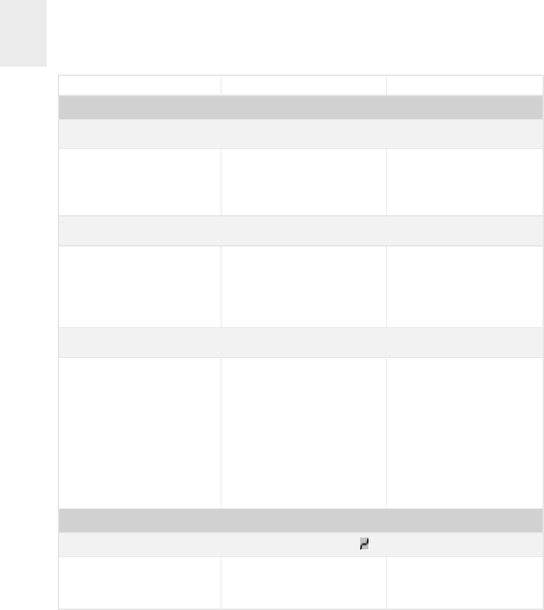
GB
34
Message E3 in the control
Inadequate cookware due to
its poor magnetic qualities.
This error message disap-
pears after eight seconds.
Otherwise, call Technical
Support.
When cooking at a level below 9, there will be fluctuations
in the power
The induction generator of
the cooker turns on and off
alternately in order to keep
the chosen cooking level.
This is not a defect.
ONLY MODELS ...604:
Excess temperature pro-
blems during cooking only
occur in extreme situations
(an extended period of time
cooking at maximum power)
or when installation is ina-
dequate.
Verify that installation has
been done in accordance
with the indications in the
instructions manual.
If an induction element goes off and the message E2 appears
Overheating of the electronics.
Fault Possible cause Possible solution
MODELS ...640 AND ...644
Continuous beeping, touch control disabled and appears on the displays
There is an object or some
liquid on top of the touch
control.
Remove any object or liquid
covering the touch control.
