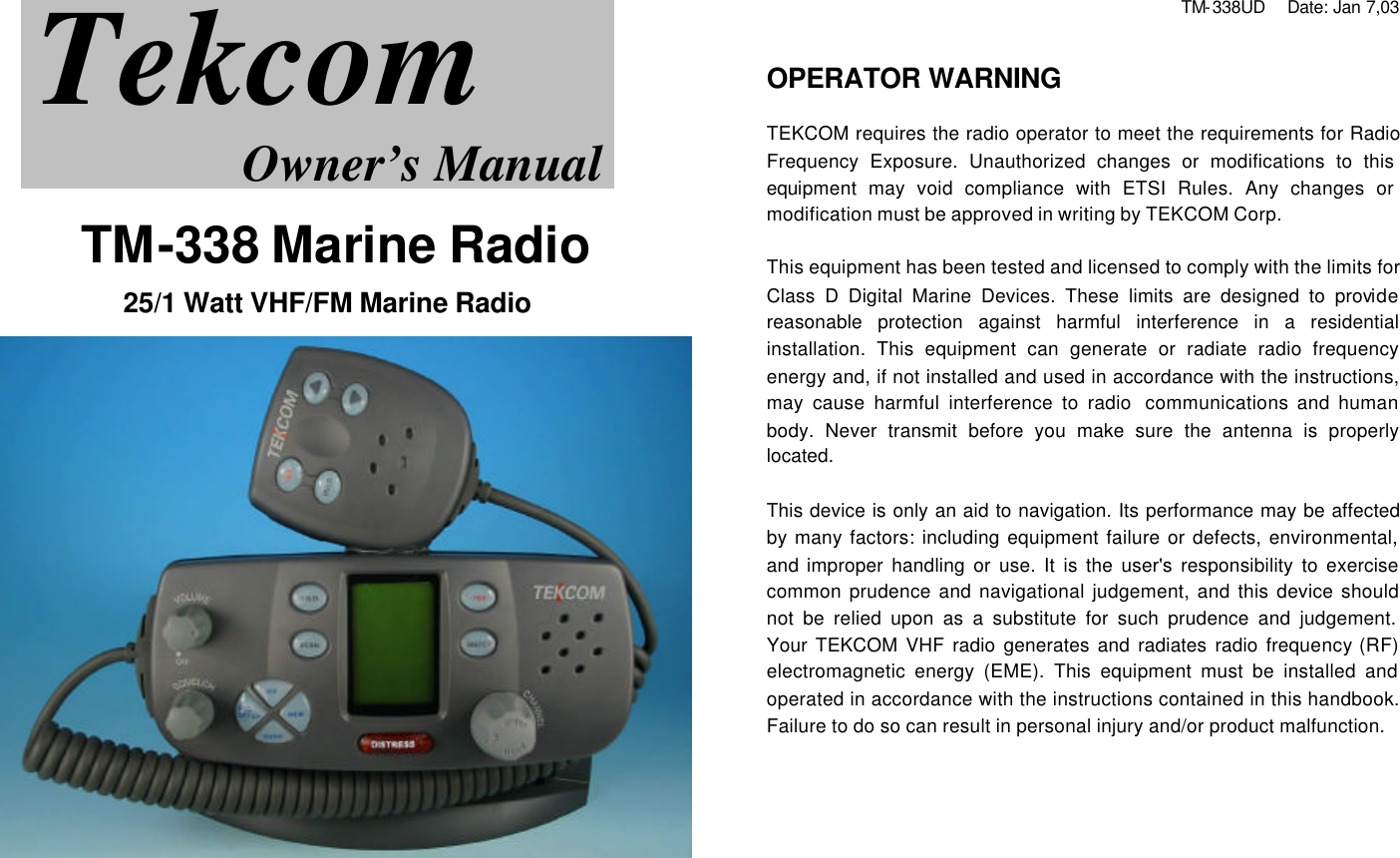
Tekcom TM-338 156-162 Marine Transceiver User Manual Revised Manual
Tekcom Industries Limited 156-162 Marine Transceiver Revised Manual
UserManual.wiki
>
Tekcom
>
TM 338 User Manual
users manual
Navigation menu
Upload a User Manual
Namespaces
Wiki Guide
HTML
PDF
Info
Views
User Manual
Discussion / Help
Navigation
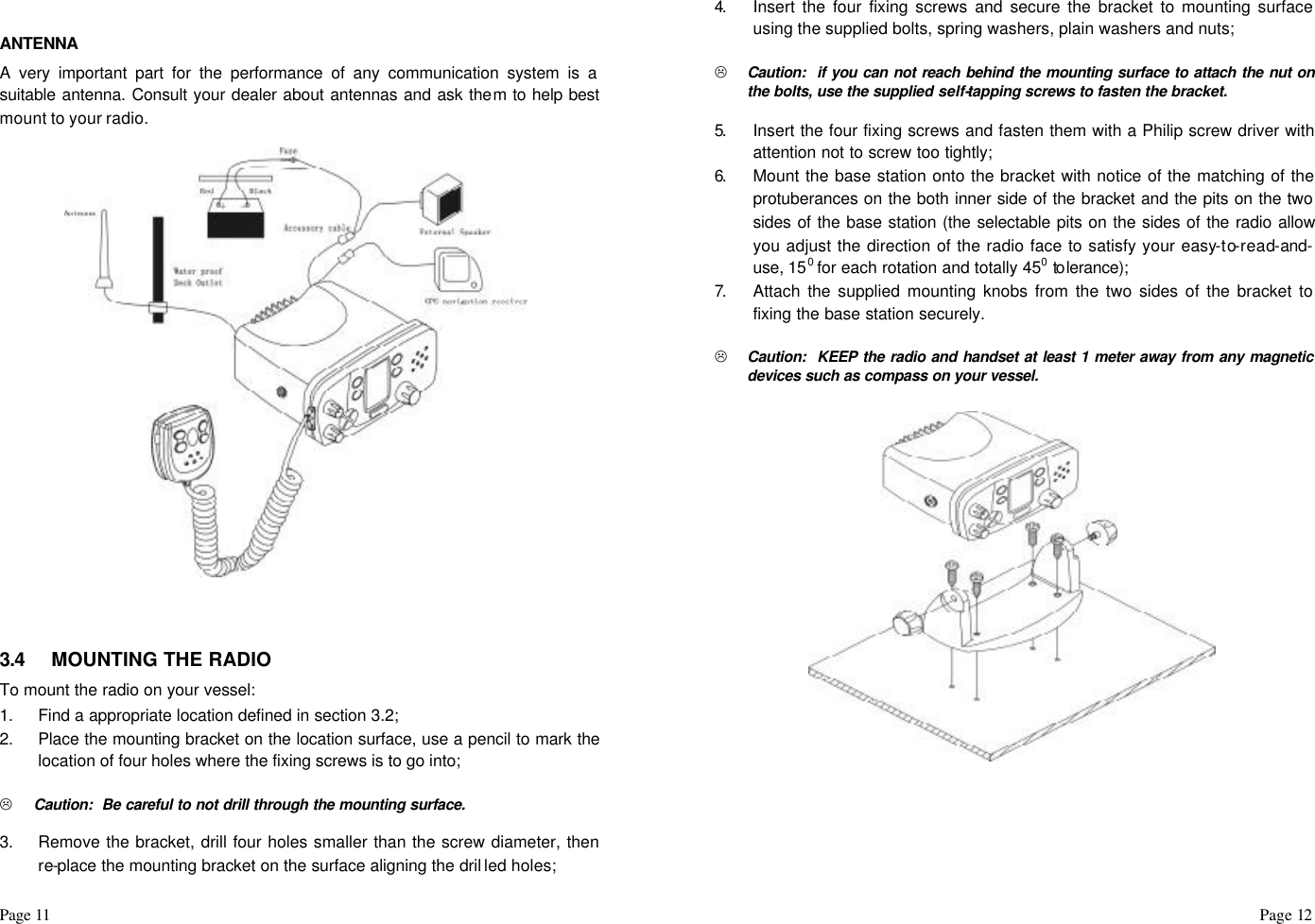
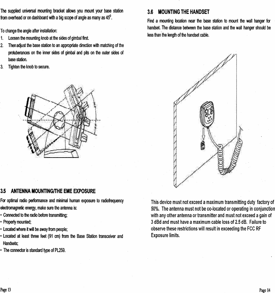
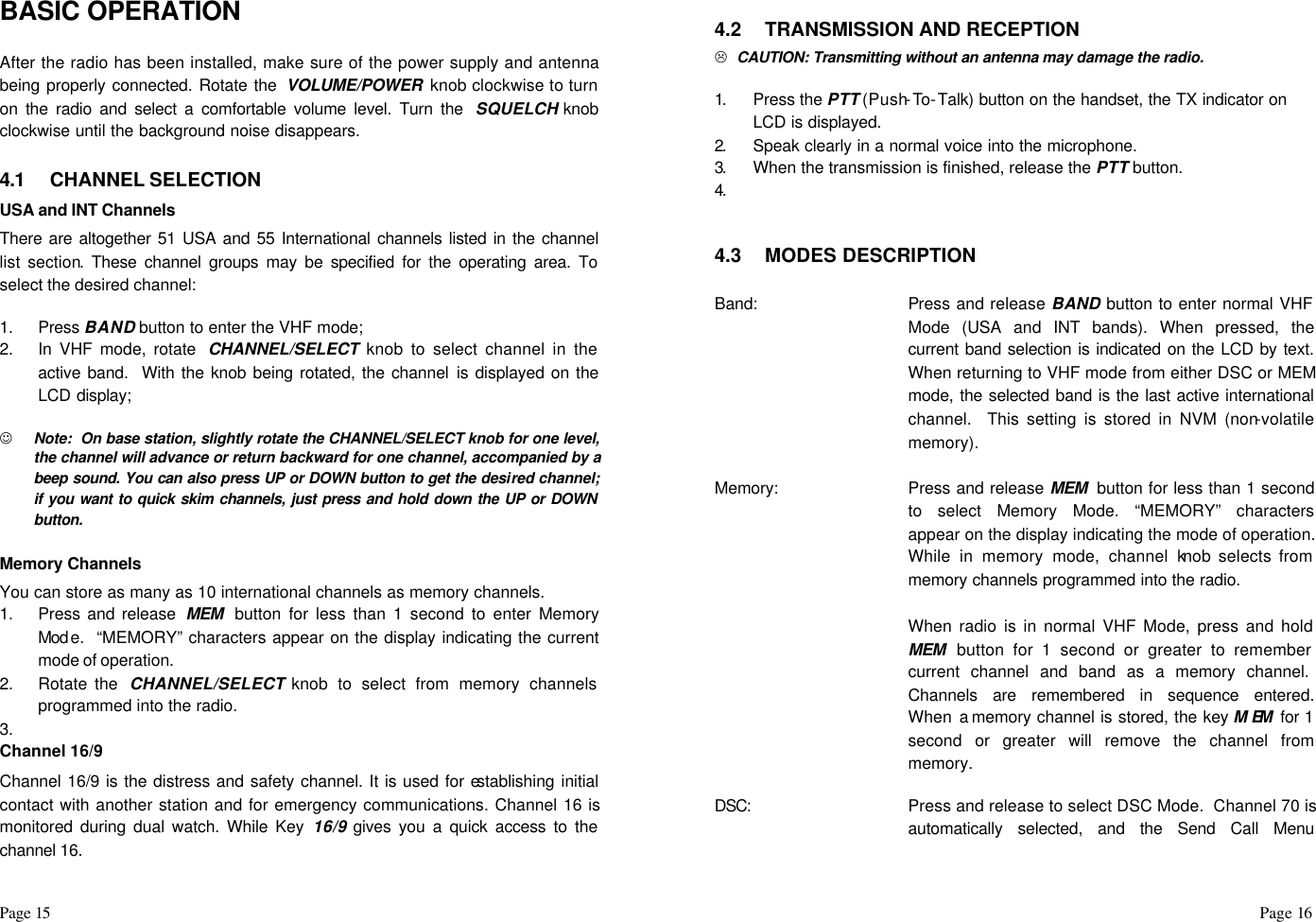
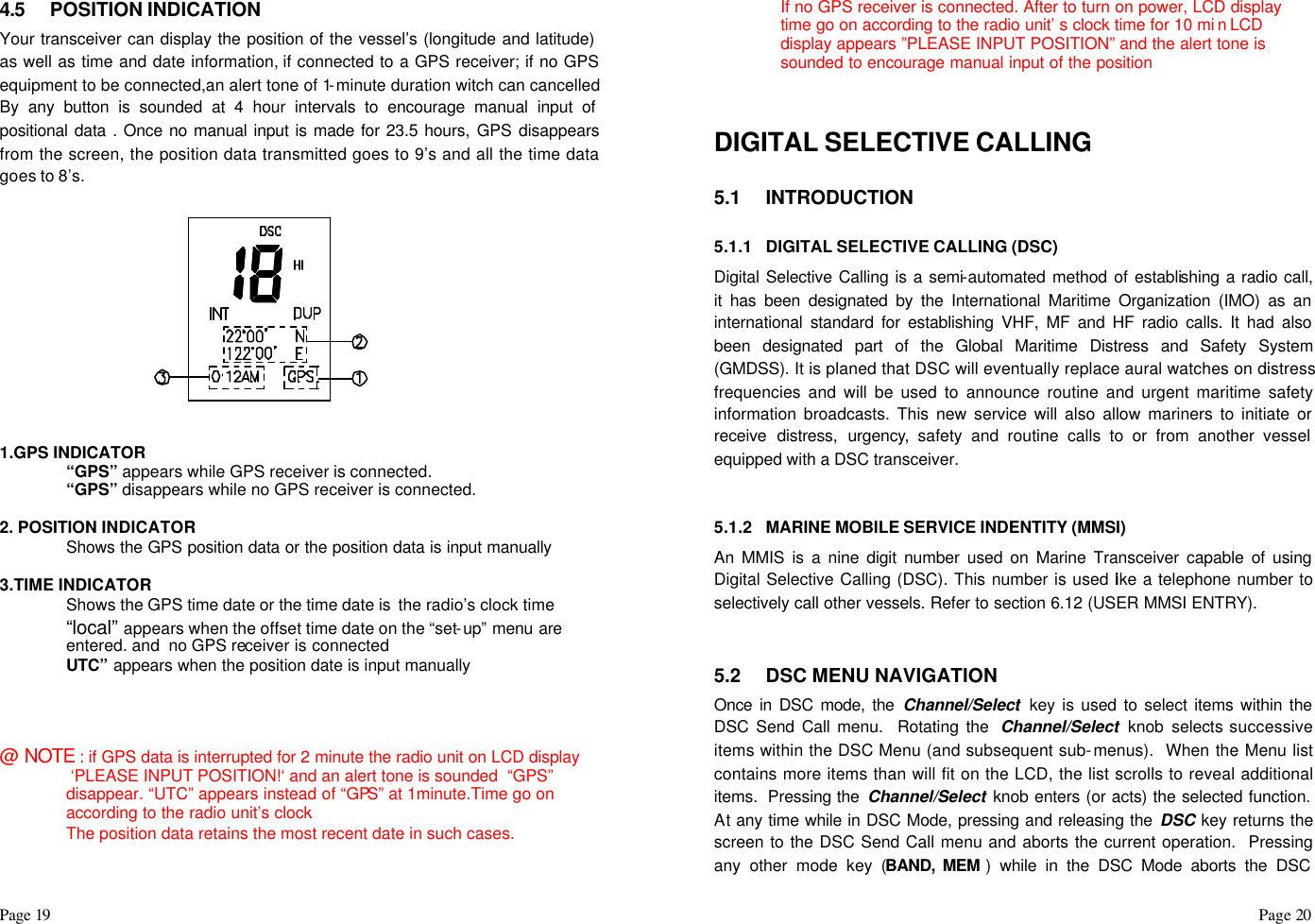
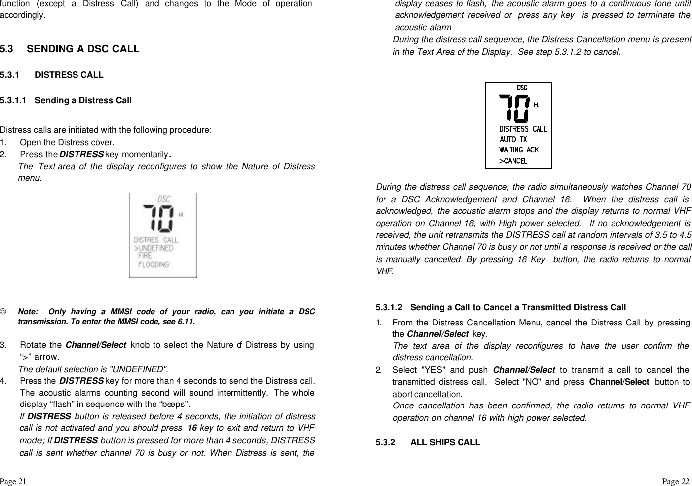
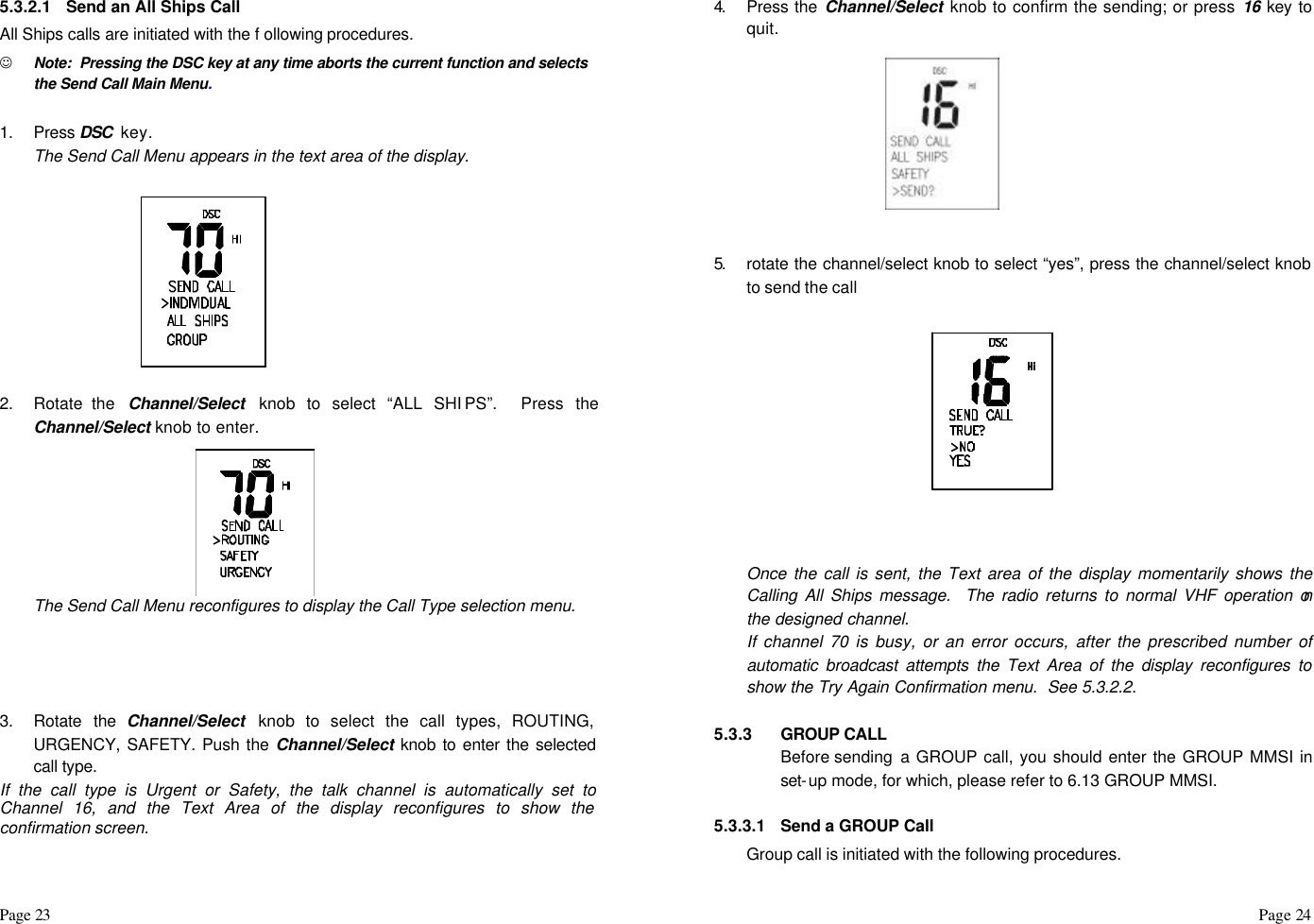
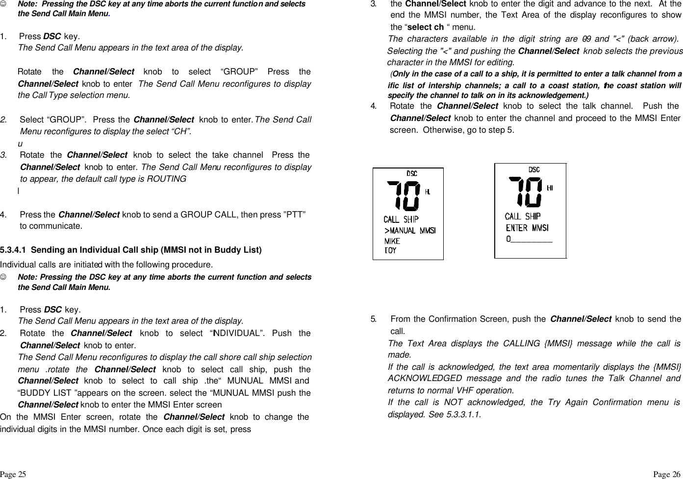

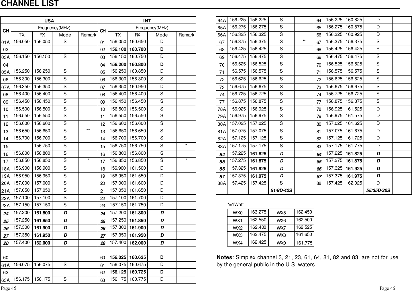
![Page 43 Page 44 MAINTENANCE Your VHF Marine Radio *** is a marine radio of water proof who can meet the requirement of JIS level 7, gives you a good reliability when using in marine circumstance. The equipment is designed to be maintenance free. To keep your radio in good working condition: l Never unscrew the equipment, either the base station or handset, for in such case, the water proof performance will be greatly damaged. l If the radio becomes dirty and dusty, wipe it clean with a moisture cloth, but pay attention to never using such solvents as benzene or alcohol, for they may damage the radio surfaces. l Once your equipment do not work properly, never allow an unqualified person to tamper with internal adjustments. Please contact the local dealer for help. TROUBLE SHOOTING Item Symptom Cause/Remedy 1 Unit can not be powered on. l Check the connection to the base station. l Check the volume control. 2 No sound comes from the speaker l Set [VOL] to a suitable level. l Set squelch to the threshold point. 3 Transmitting is impossible, or high power can not be selected. l Check to see if the PTT switch is defective. l Check to see if the microphone or MIC jack is defective. l Some channels are for low power or receive only, change to another channel. l Push H/L to select high power. 4 Low receiver sensitivity. l Check to see if the antenna being bad connected. l Check the connection between coaxial cable and base station. SPECIFICATION TX Frequency…………………………...………156.050 ~ 157.425 MHz RX Frequency.............………………………….156.025 ~162.025 MHz Channels........................…………………………..55 USA Channels 55 INT Channels 10 Memory Channels Modulation type.........................………………………..……………...FM Antenna impedance...........................………………………......50 Ohm Microphone...............................……………………......condenser type Power supply....................................…………………………..13.8V DC Sensitivity at 12dB Sinad.......................................…………….....0.5µV Adjacent Channel Rejection................................……………........70dB Audio output power.............................……………...........2W @ 8 Ohm Audio Distortion ...............................………………………..............10% RF Output Power....................…………………...High: 23W/Low: 1W Harmonic Emissions................……………...High: 80dB/Low: 60dB Dimensions (HWT)..........................................…….....71×161×147mm Weight …………………...................................…………………...1290g](https://usermanual.wiki/Tekcom/TM-338/User-Guide-333489-Page-24.png)