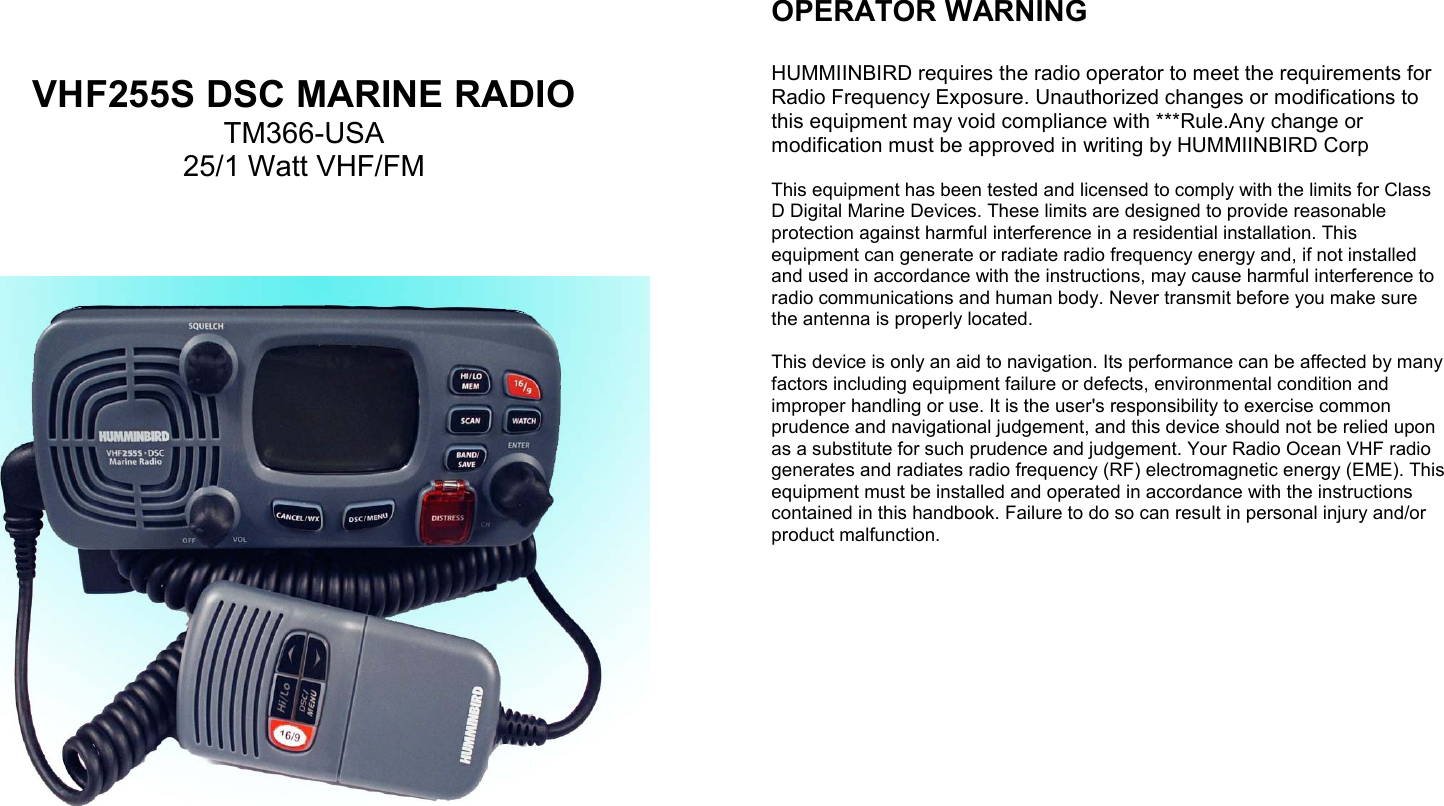
Tekcom TM-366 MARINE TRANSCEIVER User Manual USERS MANUAL
Tekcom Industries Limited MARINE TRANSCEIVER USERS MANUAL
UserManual.wiki
>
Tekcom
>
TM 366 User Manual
USERS MANUAL
Navigation menu
Upload a User Manual
Namespaces
Wiki Guide
HTML
PDF
Info
Views
User Manual
Discussion / Help
Navigation
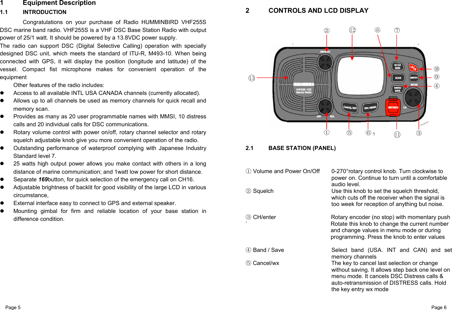
![Page 25 Page 26 5.2.4.3 ACKNOWLEDGEMENT OF AN INDIVIDUAL INCOMING CALL The radio either automatically or manual send an acknowledgement to the requesting radio depend on setting, The USA will automatically send an acknowledgement to the requesting radio within 10 seconds of receiving the call. 5.2.5 LAST CALL (RECALL THE MOST RECENT INCOMING CALL) This facility also is useful and is used frequently as routing individual call 1 Press the DSC / Menu key to enter the DSC mode LAST CALL will be pointed, press CH key to display the detail information of the last call 2 Select the working channel for individual call and press CH key, the radio summarizes the call details and ask for confirmation to send the call (send?).Press CH knob to send the call other operation as same as the section 5.6.1 5.2.6 SEND an INDIVIDUAL CALL USING THE CALL LOG The CALL LOG contains the contact details for the 20 most recent incoming calls, so you call any of them again quickly 1 Press the DSC / Menu key to enter the DSC mode, select CALL LOG, press up/down key to scroll for previous call. 2 Press the CH key to conform the choice then follow the as the ways to make the call in5.6.1 (To save this log entry you BUDDY LIST, select SAVE, then press ENT key and enter a name the logged MMSID is automatically displayed.) 5. 2.7 POS REQUEST AND POP REPLY 5. 2.71 POS REQUEST (REQUEST THE LL POSITION OF ABUDDY) The option enables you to request GPS position information from any vessel for which an MMSI number is known. 1 Select the POS REQUEST on the DSC Menu, press the CH key to enter the buddy list (<MANUAL> AND PHONEBOOK) select the one for position information. 2 The Call will be initiate and same as individual call procedures. See 5.6.1 5.2.72 POP REPLY The position relay can to send your position to another radio with this feature. Your radio must have an operating GPS receiver connected to be used to send to the position. POS relay can manually send your position or do it automatic t which depending upon on your setting the set On the manual reply, operation procedures as follow: 1 when you received POS request call, an alarm pi sounds LCD displays as follow: 2 Press the CH key to transmit your own ships’ position and time information 3 Press [CLR] to record the received information, then the screen goes back to default. 5.3. Receiving a DSC Call When a DSC call is received, the radio automatically responds based on the type of call. The information displayed on the LCD varies depending upon the call type. See chart below. 5.3.1 Receiving Distress Call 1 When a distress call is received, the radio automatically tunes to channel 16, and the Distress Alarm Tone sounds. The call date is stored in the distress. Log. Pressing any key disables the alarm. 3 When position data is included within the signal, it is displayed in the Text Area of the LCD. When no position data is included within the signal, the message "99 °99.9999X, 999 °99.9999Y" is displayed in the Text Area of the LCD. 2 You must continue to monitor channel 16 as a coast station may require assistance in any rescue attempt 5.3.2 Receiving a Distress ACK Send from a coast station 1 When a Distress Relay Call is received, the Base Station automatically tunes to Channel 16, and the Distress Alarm Tone sounds. Pressing any key disables the alarm. When position data is included within the signal, it is displayed in the Text Area of the LCD. The call date is stored in the distress log 2 You must continue to monitor channel 16 as a coast station may require assistance in any rescue attempt DISTRESS ID045007896421’09.1011N 120’20.0111E DISTRESS ID4050078964SINKING 12: 45UTC](https://usermanual.wiki/Tekcom/TM-366/User-Guide-600844-Page-13.png)
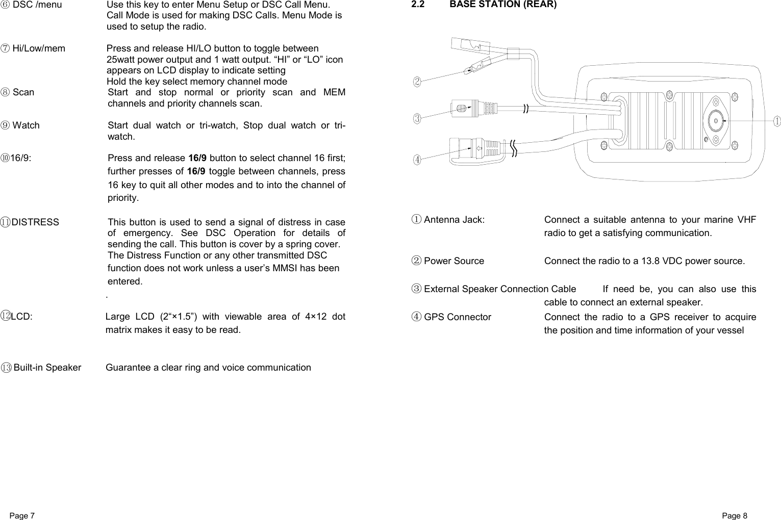
![Page 41 Page 42 7 MAINTENANCE Your VHF Marine Radio *** is a marine radio of water proof who can meet the requirement of JIS level 7, gives you a good reliability when using in marine circumstance. The equipment is designed to be maintenance free. To keep your radio in good working condition: Never unscrew the equipment, either the base station or handset, For in such case, the water proof performance will be greatly damaged. If the radio becomes dirty and dusty, wipe it clean with a moisture cloth, but pay attention to never using such solvents as benzene or alcohol, for they may damage the radio surfaces. Once your equipment does not work properly, never allow an unqualified person to tamper with internal adjustments. Please contact the local dealer for help. TROUBLE SHOOTING Item Symptom Cause/Remedy 1 Unit can not be powered on. Check the connection to the base station. Check the volume control. 2 No sound comes from the speaker Set [VOL] to a suitable level. Set squelch to the threshold point. 3 Transmitting is impossible, or high power can not be selected. Check to see if the PTT switch is defective. Check to see if the microphone or MIC jack is defective. Some channels are for low power or receive only, change to another channel. Push H/L to select high power. 4 Low receiver sensitivity. Check to see if the antenna being bad connected. Check the connection between coaxial cable and base station. 8 SPECIFICATION TX Frequency…………………………...………156.050 ~ 157.425 MHz RX Frequency 156.025 ~163.275 MHz Channels........................…………………………..55 USA Channels 55 INT Channels 10 Memory Channels Modulation type.........................………………………..……………...FM Antenna impedance...........................………………………......50 Ohm Microphone...............................……………………......condenser type Power supply....................................…………………………..13.8V DC Sensitivity at 12dB Sinad.......................................…………….....0.5µµµµV Adjacent Channel Rejection................................……………........70dB Audio output power.............................……………...........2W @ 8 Ohm Audio Distortion ...............................………………………..............10% RF Output Power....................…………………...High: 25W/Low: 1W Harmonic Emissions................……………...High: 80dB/Low: 60dB Dimensions (HWT)..........................................…….....71×161×147mm Weight …………………...................................…………………...1290g](https://usermanual.wiki/Tekcom/TM-366/User-Guide-600844-Page-21.png)