Tekelek Europe 377A Wireless Fuel Oil level monitoring system User Manual page 1
Tekelek Europe Ltd Wireless Fuel Oil level monitoring system page 1
Contents
- 1. User manual page 1
- 2. User manual page 2
- 3. addition to user guide
User manual page 1
Wireless Fuel Oil Level Monitoring System
INSTALLATION INSTRUCTIONS
INSTALLATION STEPS
1. CONFIGURING THE RECEIVER
Determine the total tank height either by making a direct
measurement or using the Table on the reverse side.
The Receiver come
s programmed from the factory for
standard 275 or 330 gal upright (Vertical) Steel tanks.
The Rocket 7000 system is capable of measuring fuel
level in a tank up to 10 ft in height. A row of DIP
switches is located on
the back of the Receiver. After
determining the tank height use Table I to locate the
correct DIP switch setting for your tank.
Use the tip of a small screwdriver or a pen to set the
switches according to the table. Toggling an individual
switch at the
top (towards the antenna) will put it into the
U
sing a pipe wrench, if necessary, loosen the metal plug
in an unused opening at the top of your tank, but leave it
in the tank until you’re ready to mount the Rocket tran
s-
mitter onto the tank. This will avoid unnecessary fuel oil
3. SYNCHRONIZING THE RECEIVER TO THE TRANSMITTER
E
ach Rocket 7000 Transmitter is manufactured to have
its own unique digital signature. The Receiver must be
synchronized (“matc
hed”) to the Transmitter and after
that the Receiver will only respond to signals received
from that Transmitter. This allows m
ultiple Transmitter/
Receiver pairs to be located in the same area. Also,
multiple Receivers can be synchronized to the same
Transmitter.
To synchronize the Receiver to the Transmitter, plug the
Receiver into a convenient 110 Volt electrical outlet th
at
is powered ON. The digital LCD display on the receiver
will show a flashing top bar as shown in the figure. The
bar will fl
ash for about 2 minutes which should allow
plenty of time to synchronize with the Transmitter. Hold
the Transmitter against the
right side of the Receiver so
that the “dots” on the side of each device are essentially
touching for about 20 seconds. During the synchroniz
a-
tion process the bars will go from one to ten. When all
ten bars appear, they will flash to indicate that the sy
n-
chronization process is complete.
The transmitter stays in transmit mode for about 2 mi
n-
2. PREPARING FOR MOUNTING ONTO TANK
Transmitter “Rocket” with gasket
Receiver with LCD display
Metal Adapter (2” NPT) No. 7020
Mounting Screws (2)
The Rocket 7000 System includes
the following components:
Pipe Wrench
Thread Sealant
Star/Philips Screw driver
Tools Required:
TANK
HEIGHT
TROUBLE SHOO
T
ING
N
OTE:
In the event of a power failure or if the Receiver is unplugged, it
is not nece
s-
sary to re
-
synchronize the Receiver with the Transmitter
. When the Receiver is
back under power, the top bar on the LCD displa
y will flash for 2 minutes and the
display will then go blank until a signal is received from the Transmitter, which could
take
up to one hour.
FLASHING TRIANGE
—
NO BARS DISPLAYED
Indicates that the receiver has not received a signal for
two hours. Possible causes are:
•
Receiver not matched to transmitter
—
Resynchronize
•
Receiver location not suitable
—
Relocate receiver
•
Failed Battery
—
Replace Batter
y (use 3 Volt CR2430)
•
Moisture inside Transmitter (broken seal)
FLASHING TRIANGE
—
MIDDLE BAR DISPLAYED
Indicates that the Transmitter is not receiving an echo from
its ultrasonic signal inside the tank. Likely cause:
•
C
ondensation on the sensing surface at the bottom of
the Transmitter. Allow time to dry. If condition pe
r-
sists, remove Transmitter from the tank and clean
sensor surface and verify that the seal is undamaged.
OIL EQUIPMENT MANUFACTURING LLC
•
4 HERSHEY DRIVE
•
ANSONIA, CT 06401
Tel: 203
-
736
-
8886
•
Fax: 800
-
532
-
3073
• www.oil
-
equip
-
mfg.com • E
-
mail: info@oil
-
equip
-
mfg.com
T
he Rocket 7000 System comes with a metal adapter that
will screw into a 2” NPT opening in the tank. (For 1
½
” or
1
¼
” NPT openings, please contact a participating distrib
u-
tor for a correctly sized adapter). Put pipe sealant on the
Adapter threads and tighten the Adapter into the tank
opening. Fas
ten the Transmitter into the Adapter using
the two Philips head screws provided.
Do not over
tighten.
4. INSTALLING THE TRANSMITTER
INSTALLATION STEPS
—
CONTINUED
C
ONGRATULATIONS!
You have completed the installation of the Rocket 7000 sy
s-
tem. If the Transmitter was installed within 2 minutes after the synchronization process,
the Receiver should now show the corr
ect fuel level. Thereafter, the transmitter will
send the fuel level to the Receiver once every hour. If you have a mechanical
float
gauge on your tank, you can now verify that the Rocket 7000 system is reading the
same level.
F
CC ID: S6T
-
377A
This device complies with Part 15 of the FCC Rules. Operation is subject to the follo
w-
ing two conditions: (1) This device may not cause harmful interference, and (2) This
device must accept any interference receiv
ed, including interference that may cause
undesired operation.
9
-
5246
-
02
DIP switch 1 is used
for enabling (ON
-
Default) or disabling
(OFF) the audible low
fuel level warning.
The Rocket 7000 system uses ultrasonic radio wave technology to measure the fuel
level in the tank. It then uses wireless trans
mission to send the measured fuel level to
the Receiver. To preserve battery life, the measurements and transmissions are done
once every hour.
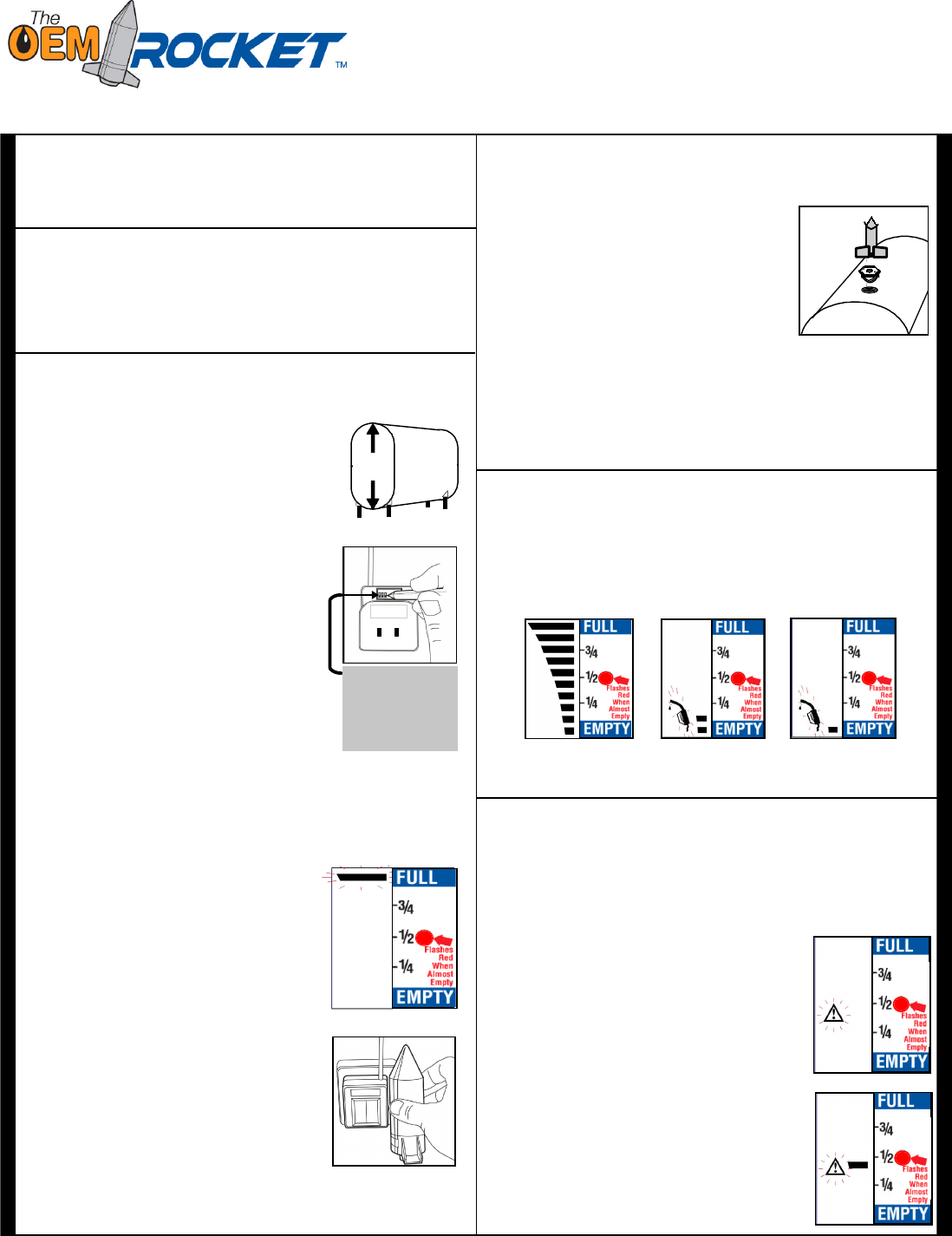
NORMAL RECEIVER LCD SCREEN DISPLAYS
FULL
ALMOST EMPTY
EMPTY
LIGHT FLASHES
BEEPS EVERY HOUR
NORMAL OPERATION