Tekelek Europe 750 Liquid level ultrasonic tank sensor User Manual
Tekelek Europe Ltd Liquid level ultrasonic tank sensor
User manual
Installation
Sheet
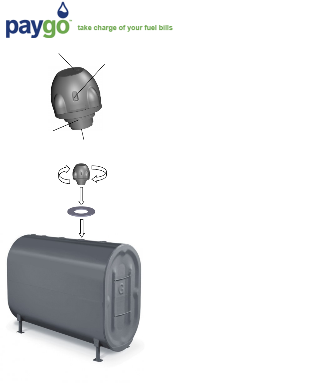
LED Indicator
Hot Spot
Mul-thread
adapter Ultrasonic
horn STEP 1: Using a mobile device, conrm that
your home Wi-Fi network is available at your
tank*
STEP 2: Aaching the monitor to your tank.
a. Idenfy a spare threaded opening
(typically 2”). Remove and store the cap.
b. Ensure the opening is located away from
the sides of the tank, and is clear of inter-
nal obstrucons to ensure a good quality
reading.
c. Place the foam gasket over the opening.
d. Screw the monitor clockwise into the
threaded opening.
DO NOT OVER-TIGHTEN THE SENSOR
Thank you for acquiring the Paygo tank monitor.
This device uses ultrasonic technology to meas-
ure the liquid level of your tank, and then sends
the informaon via your Wi-Fi connecon to
your local fuel oil supplier.
Technical Specicaons
Supports 802.11 b/g/n Wi-Fi
Wireless frequency: 2.412GHz—2.462GHz
Fits onto tanks with a 2”, 1 1/2” or 1 1/4” threaded
opening. 2” recommended.
Power output nominal 15dBm
Tank depth measurement: 5” to 115”
Typically 7.5+ years baery life using 3.6v Lithium cell
Operaonal temperature range 14°F to +122°F
Dimensions 4.3”(l) x 4.3”(w) x 4.25”(h). Weight 8 oz.
* For weak Wi-Fi signal, use a Paygo monitor with an
external Wi-Fi antenna . The external antenna prod-
uct opon has a reverse polarity SMA connector.
For FCC compliance the external antenna should have
not have a gain exceeding 7dBi.
FCC ID: S6T750
This device complies with Part 15 of the FCC Rules. Operaon is subject to the following two condions:
(1) This device may not cause harmful interference, and
(2) This device must accept any interference received, including interference that may cause undesired operaon.
WARNING: Changes or modicaons not expressively approved by the party responsible for compliance could void the user's authority to operate the equipment.
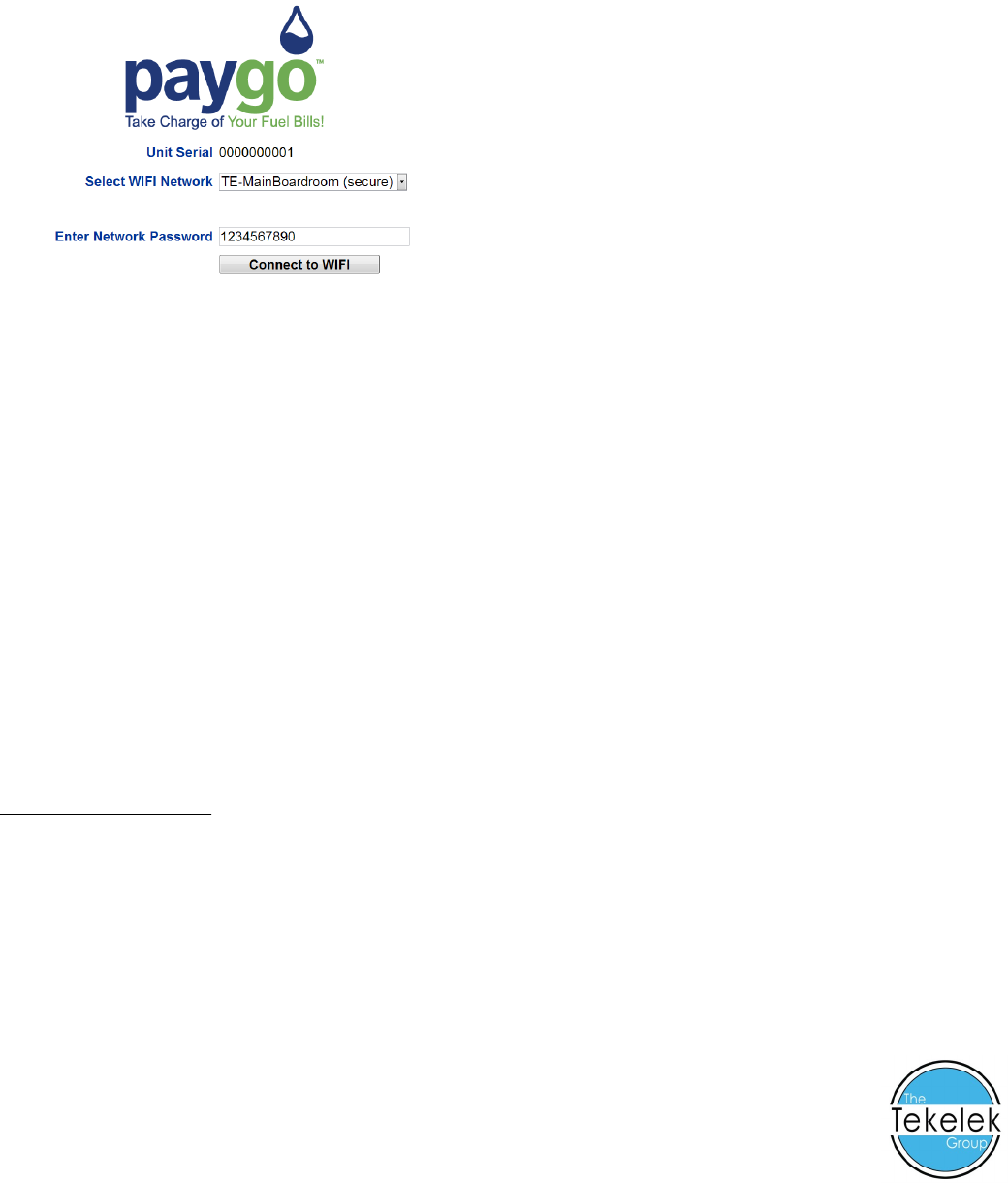
STEP 3: Connecng the monitor to your Wi-Fi network
a. Hold the supplied magnet against the “Hot spot” for 5 seconds, unl the LED turns red.
b. Using a mobile device, search for a Wi-Fi network beginning with “PAYGO” and connect to it.
c. Open a web browser and enter 192.168.4.1 into the address bar. The Paygo page will load.
d. Choose your Wi-Fi network (SSID) from the list, or choose “manually entered” and carefully enter
the Wi-Fi network name (SSID).
e. Enter the Wi-Fi Password and click on the buon “Connect to WIFI”.
f. The monitor’s LED will turn green. Wait approximately 20 seconds and observe if the LED ashes
green or red several mes.
g. Green ashes indicate a successful connecon to your Wi-Fi network. Red ashes mean an unsuc-
cessful connecon and the number of ashes may be counted to diagnose what the problem my be
from the list below.
STEP 4: Manually tesng monitor (once setup has been completed successfully)
a. Hold the magnet against the “Hot spot” for 1 second, unl the LED turns green.
b. Wait approximately 20 seconds observe if the LED ashes green or red.
c. Green ashes indicate a successful test connecon and data transmission. Red ashes mean an un-
successful connecon and the number of ashes may be counted to diagnose what the problem my
be from the list below.
Red LED ash code list
1 Flash – Unable to nd the Wi-Fi network (or Wi-Fi setup incomplete).
2 Flashes – Wi-Fi network unable to connect (i.e. poor signal or MAC ltering enabled on the router).
3 Flashes – Wi-Fi Password Incorrect (note password is case-sensive).
4 Flashes – Server endpoint unavailable (no web service detected).
5 Flashes – No response from server (data sent, but nothing received).
6 Flashes – Invalid response to the server (i.e. a 404 HTTP response returned).
7 Flashes – Firmware download failed (med out, not found or wrong type).
8 Flashes – Low baery (a depleted baery will eventually prevent Wi-Fi connecons).
9 Flashes – Wi-Fi Module no response (crical fault).
Designed and developed by Tekelek Europe Ltd, Shannon, Co. Clare, Ireland
9-5782-01