Tekk XU-1000 LICENSED PORTABLE TRANSMITTER User Manual XU1000 UserMan r2
Tekk International Inc. LICENSED PORTABLE TRANSMITTER XU1000 UserMan r2
UserManual.wiki
>
Tekk
>
XU 1000 User Manual
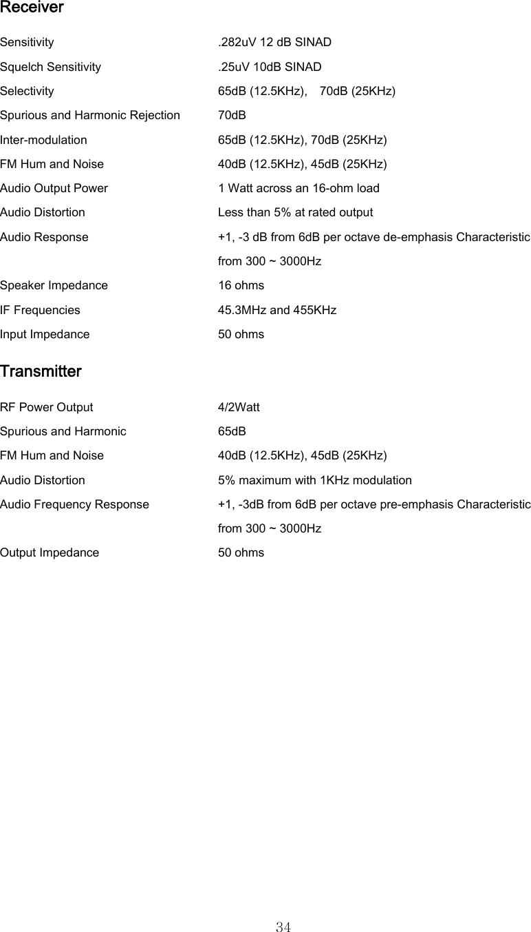
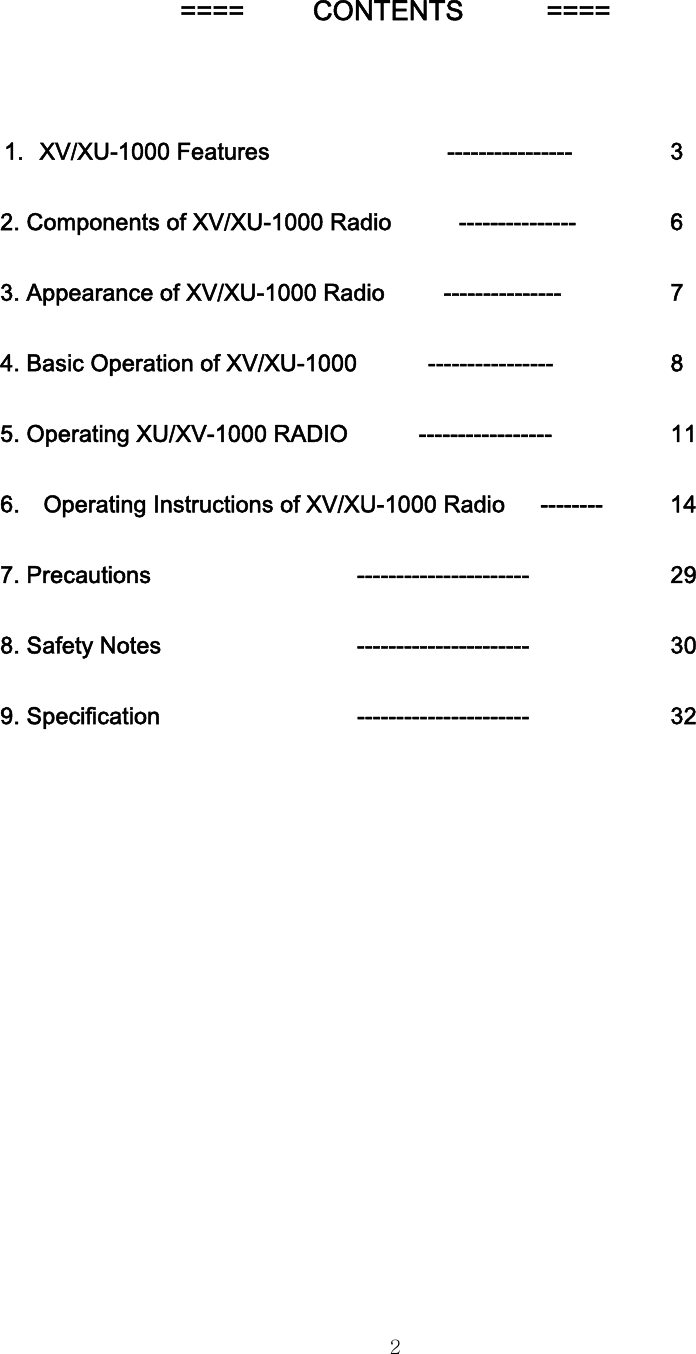
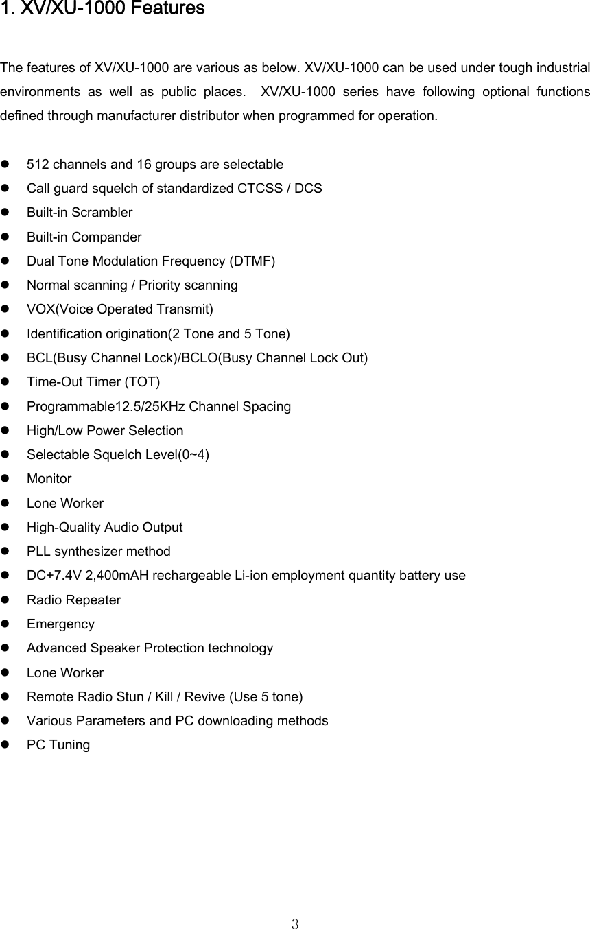
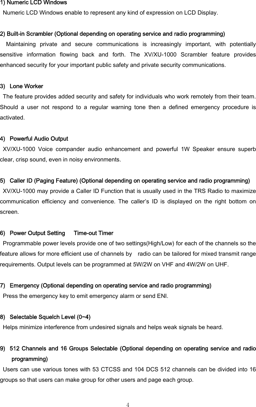
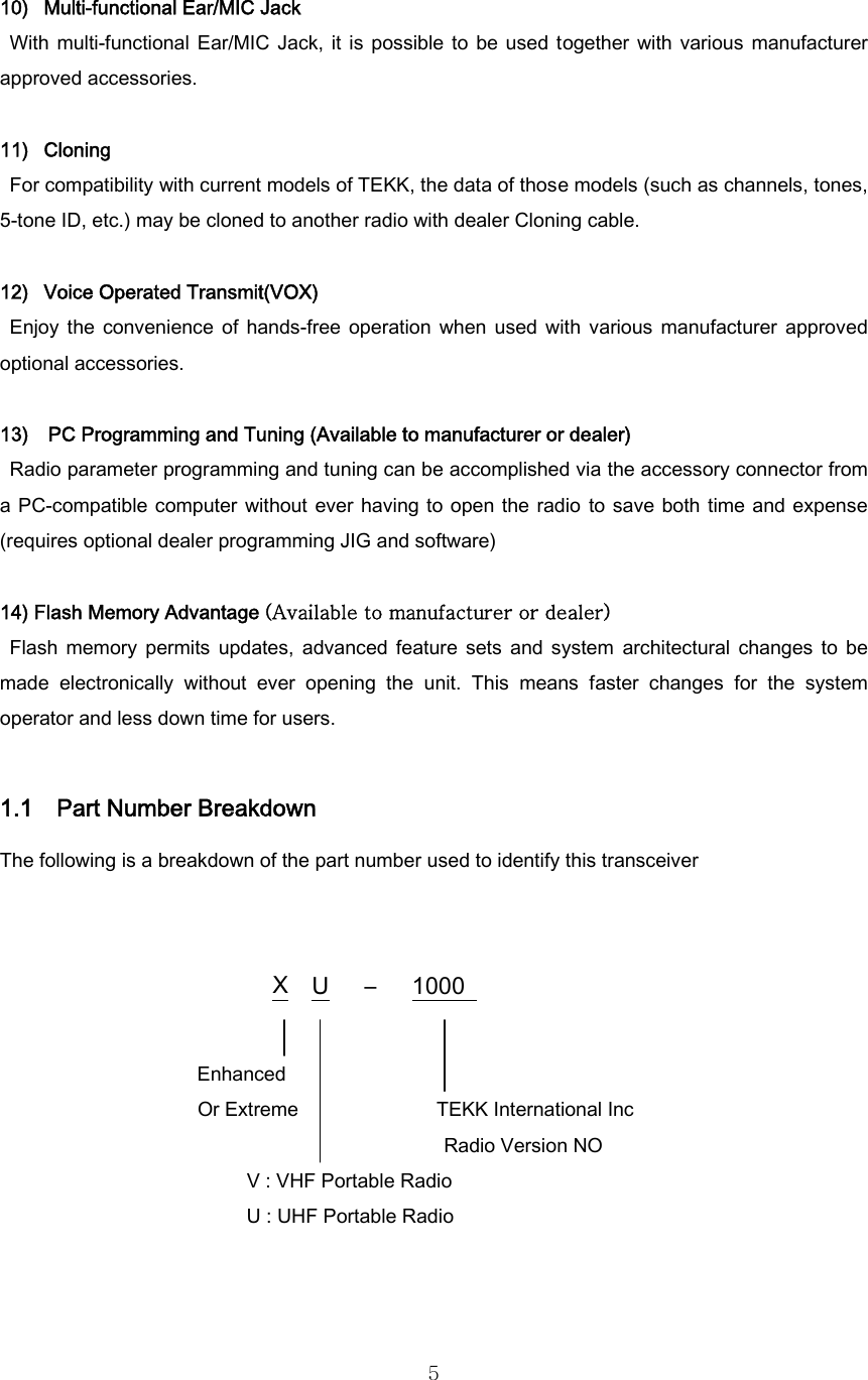
USERS MANUAL
Navigation menu
Upload a User Manual
Namespaces
Wiki Guide
HTML
PDF
Info
Views
User Manual
Discussion / Help
Navigation

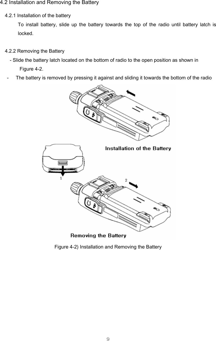
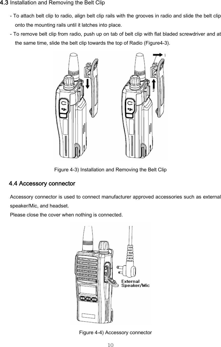
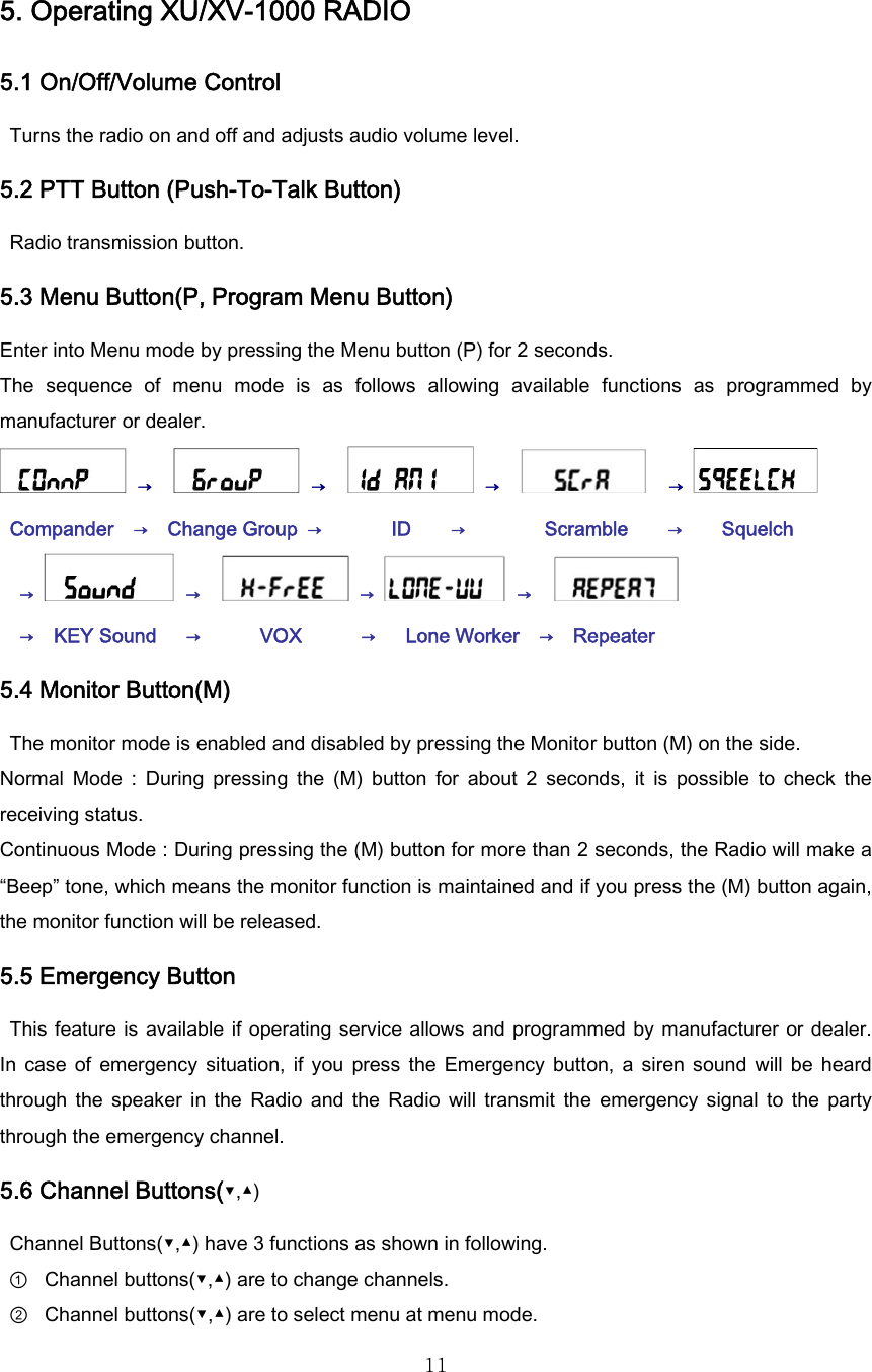
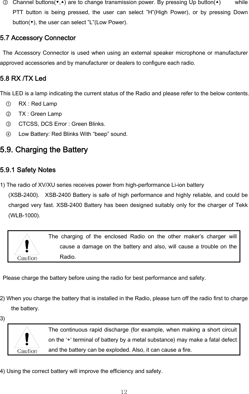
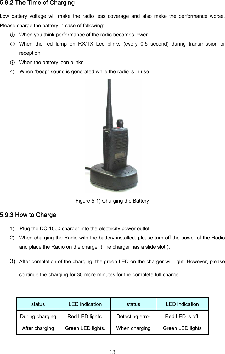

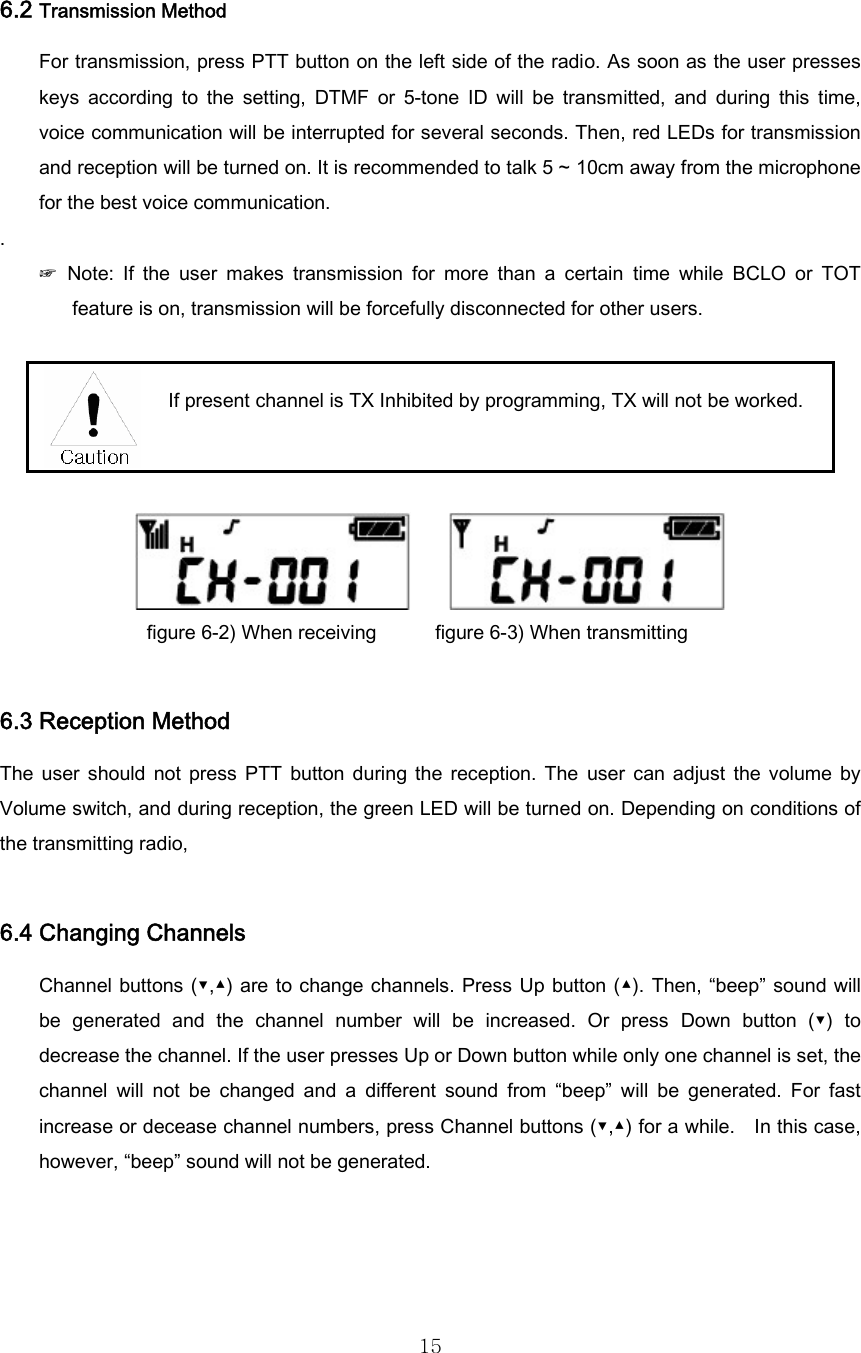
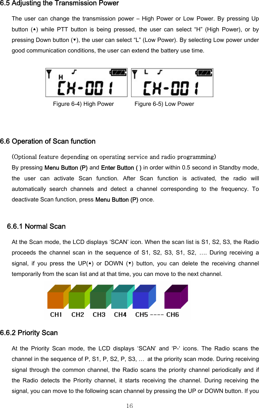
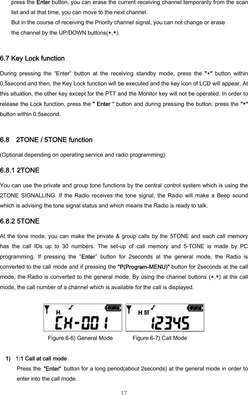
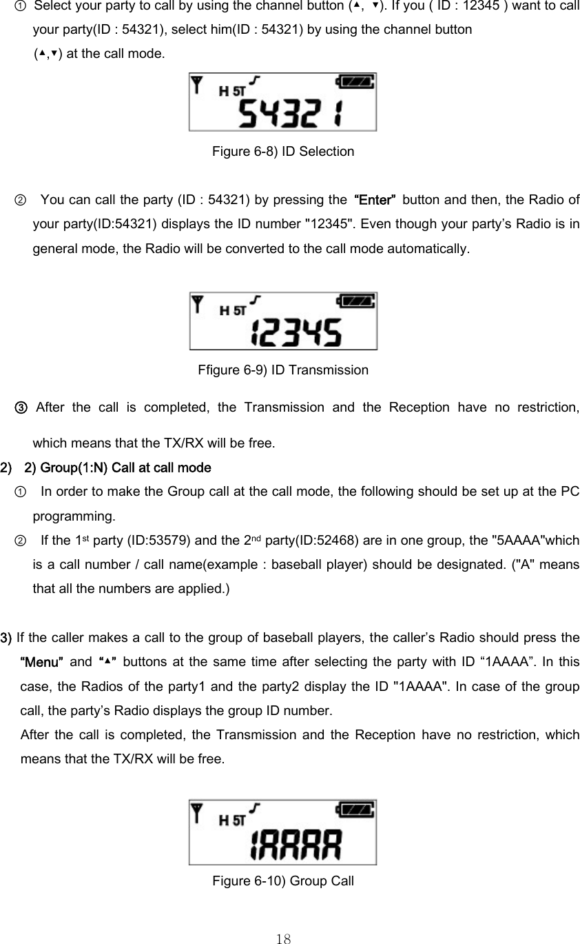
![243. Select squelch sensitivity -0~5- by pressing Channel buttons (▼, ▲), and press Enter button( ) to save the level . 4. Exit Menu mode by pressing Menu Button(P). 6.13.6 Set KEY Sound Set Key Sound menu is to decide whether to generate sound or not when the user presses four buttons . By PC Program and menu, it could be set. 1. Enter into Menu mode. 2. Select “Sound” by pressing Channel buttons (▼,▲), and press Enter button( ). . Figure 6-19) Key Sound Screen 3. Select On(y) or Off (n) by pressing Channel buttons (▼,▲), and save the selected status by pressing Enter button( ). 4. Exit Menu mode by pressing Menu Button(P) button. Select “Off”. Then, the “ “ symbol will disappear on the LCD. 6.13.7 Set VOX Set VOX is to enable users to make transmission for VOX without pressing PTT button. (This function could be available with Ear Mic [External VOX]). By PC Program and menu, it could be set. 1. Enter into Menu mode. 2. Select “H-FrEE” by pressing Channel buttons (▼,▲), and press Enter button( ).](https://usermanual.wiki/Tekk/XU-1000/User-Guide-900046-Page-24.png)