Tekk XV-1000 LICENSED PORTABLE TRANSMITTER User Manual UserMan XV1000
Tekk International Inc. LICENSED PORTABLE TRANSMITTER UserMan XV1000
Tekk >
USERS MANUAL
XV-1000 / XU-1000 Portable Radio
Service Manual
* This Service manual is subject to change according to improvement of XV-1000 / XU-1000
Portable Radio without notice.
* Version #2 (February 5, 2008)
2
==== CONTENTS ====
1. XV/XU-1000 Features ---------------- 3
2. Components of XV/XU-1000 Radio --------------- 6
3. Appearance of XV/XU-1000 Radio --------------- 7
4. Basic Operation of XV/XU-1000 ---------------- 8
5. Operating XU/XV-1000 RADIO ----------------- 11
6. Operating Instructions of XV/XU-1000 Radio -------- 14
7. Precautions ---------------------- 29
8. Safety Notes ---------------------- 30
9. Specification ---------------------- 32
3
1. XV/XU-1000 Features
The features of XV/XU-1000 are various as below. XV/XU-1000 can be used under tough industrial
environments as well as public places. XV/XU-1000 series have following optional functions
defined through manufacturer distributor when programmed for operation.
z 512 channels and 16 groups are selectable
z Call guard squelch of standardized CTCSS / DCS
z Built-in Scrambler
z Built-in Compander
z Dual Tone Modulation Frequency (DTMF)
z Normal scanning / Priority scanning
z VOX(Voice Operated Transmit)
z Identification origination(2 Tone and 5 Tone)
z BCL(Busy Channel Lock)/BCLO(Busy Channel Lock Out)
z Time-Out Timer (TOT)
z Programmable12.5/25KHz Channel Spacing
z High/Low Power Selection
z Selectable Squelch Level(0~4)
z Monitor
z Lone Worker
z High-Quality Audio Output
z PLL synthesizer method
z DC+7.4V 2,400mAH rechargeable Li-ion employment quantity battery use
z Radio Repeater
z Emergency
z Advanced Speaker Protection technology
z Lone Worker
z Remote Radio Stun / Kill / Revive (Use 5 tone)
z Various Parameters and PC downloading methods
z PC Tuning
4
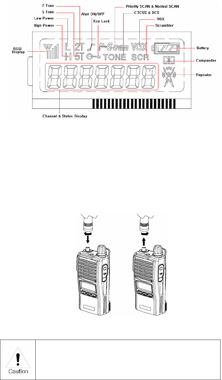
1) Numeric LCD Windows
Numeric LCD Windows enable to represent any kind of expression on LCD Display.
2) Built-in Scrambler (Optional depending on operating service and radio programming)
Maintaining private and secure communications is increasingly important, with potentially
sensitive information flowing back and forth. The XV/XU-1000 Scrambler feature provides
enhanced security for your important public safety and private security communications.
3) Lone Worker
The feature provides added security and safety for individuals who work remotely from their team.
Should a user not respond to a regular warning tone then a defined emergency procedure is
activated.
4) Powerful Audio Output
XV/XU-1000 Voice compander audio enhancement and powerful 1W Speaker ensure superb
clear, crisp sound, even in noisy environments.
5) Caller ID (Paging Feature) (Optional depending on operating service and radio programming)
XV/XU-1000 may provide a Caller ID Function that is usually used in the TRS Radio to maximize
communication efficiency and convenience. The caller’s ID is displayed on the right bottom on
screen.
6) Power Output Setting Time-out Timer
Programmable power levels provide one of two settings(High/Low) for each of the channels so the
feature allows for more efficient use of channels by radio can be tailored for mixed transmit range
requirements. Output levels can be programmed at 5W/2W on VHF and 4W/2W on UHF.
7) Emergency (Optional depending on operating service and radio programming)
Press the emergency key to emit emergency alarm or send ENI.
8) Selectable Squelch Level (0~4)
Helps minimize interference from undesired signals and helps weak signals be heard.
9) 512 Channels and 16 Groups Selectable (Optional depending on operating service and radio
programming)
Users can use various tones with 53 CTCSS and 104 DCS 512 channels can be divided into 16
groups so that users can make group for other users and page each group.

5
10) Multi-functional Ear/MIC Jack
With multi-functional Ear/MIC Jack, it is possible to be used together with various manufacturer
approved accessories.
11) Cloning
For compatibility with current models of TEKK, the data of those models (such as channels, tones,
5-tone ID, etc.) may be cloned to another radio with dealer Cloning cable.
12) Voice Operated Transmit(VOX)
Enjoy the convenience of hands-free operation when used with various manufacturer approved
optional accessories.
13) PC Programming and Tuning (Available to manufacturer or dealer)
Radio parameter programming and tuning can be accomplished via the accessory connector from
a PC-compatible computer without ever having to open the radio to save both time and expense
(requires optional dealer programming JIG and software)
14) Flash Memory Advantage (Available to manufacturer or dealer)
Flash memory permits updates, advanced feature sets and system architectural changes to be
made electronically without ever opening the unit. This means faster changes for the system
operator and less down time for users.
1.1 Part Number Breakdown
The following is a breakdown of the part number used to identify this transceiver
X U – 1000
Enhanced
Or Extreme TEKK International Inc
Radio Version NO
V : VHF Portable Radio
U : UHF Portable Radio
6
Model History Table
Model Name Frequency Range RF Power Channel Spacing Remark
XV-1000 136~174MHz 5/2Watt 12.5 / 25KHz
XU-1000 405~475MHz 4/2Watt 12.5 / 25KHz
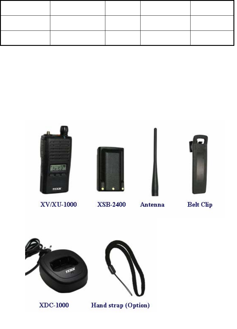
2. Components of XV/XU-1000 Radio
* Components could be changed by buyer request.
Figure 1-1) standard components of XV/XU-1000 Radio
7
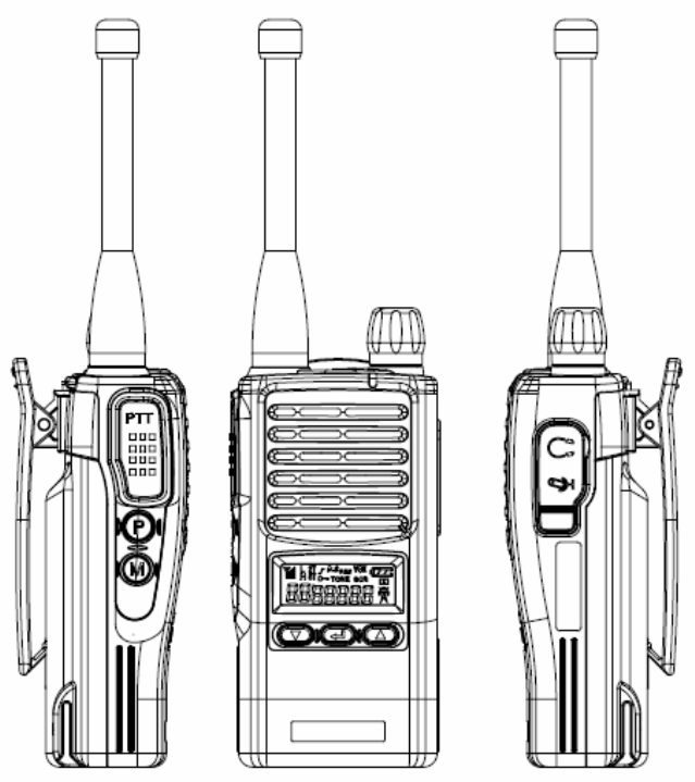
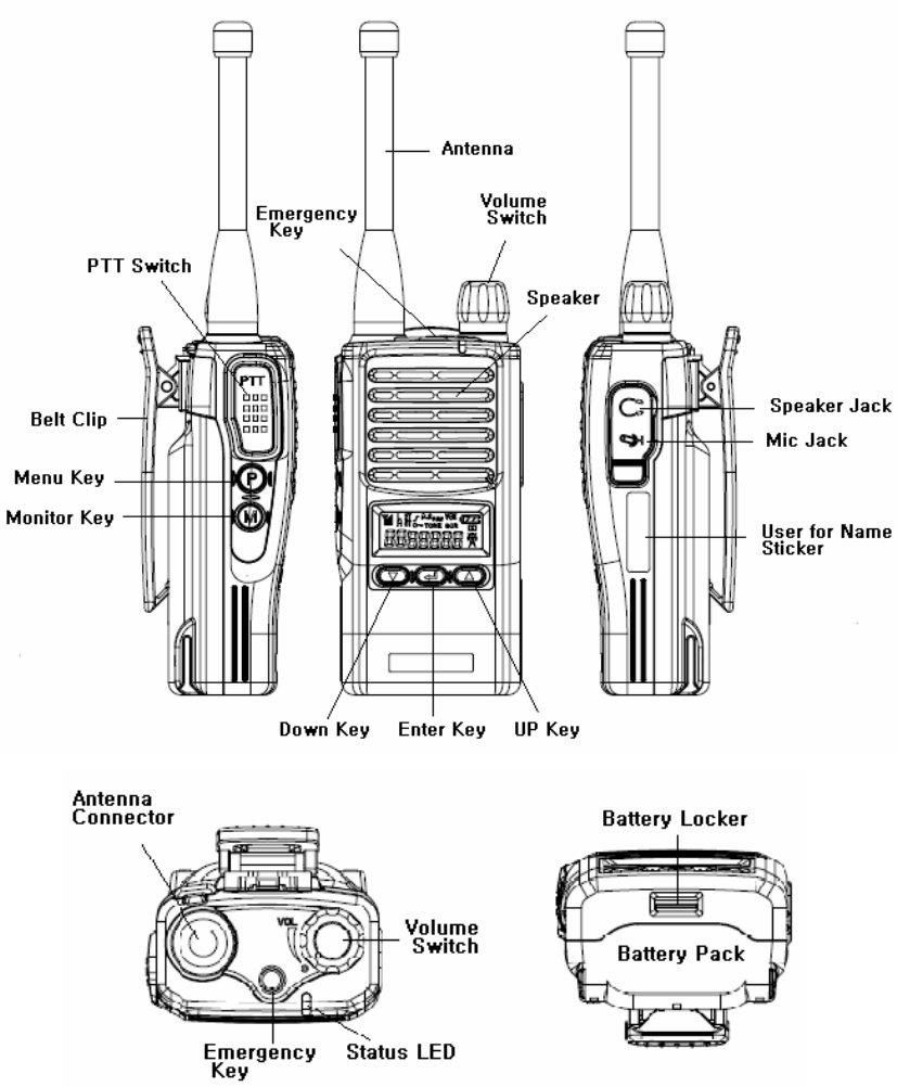
3. Appearance of XV/XU-1000 Radio
Figure 3-1) Appearance of XV/XU-1000 Radio
8
Figure 3-2) XV/XU-1000 CD Indications
4. Basic Operation of XV/XU-1000
Pease read this manual carefully before using XV/XU series Radio.
This manual contains important information about using Radio.
4.1 Installation and Removing the Antenna
To install the antenna, insert the antenna into antenna connector and screw the antenna clockwise.
To remove the antenna, screw the antenna counter clockwise.
Figure 4-1) Installation and Removing the Antenna
When installation of the antenna, giving a strong pressure to the Radio
or pulling the antenna with a strong power from the Radio can damage
the antenna connector, which may cause the Radio to have a critical
problem.
9
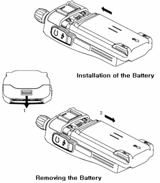
4.2 Installation and Removing the Battery
4.2.1 Installation of the battery
To install battery, slide up the battery towards the top of the radio until battery latch is
locked.
4.2.2 Removing the Battery
- Slide the battery latch located on the bottom of radio to the open position as shown in
Figure 4-2.
- The battery is removed by pressing it against and sliding it towards the bottom of the radio
Figure 4-2) Installation and Removing the Battery
10
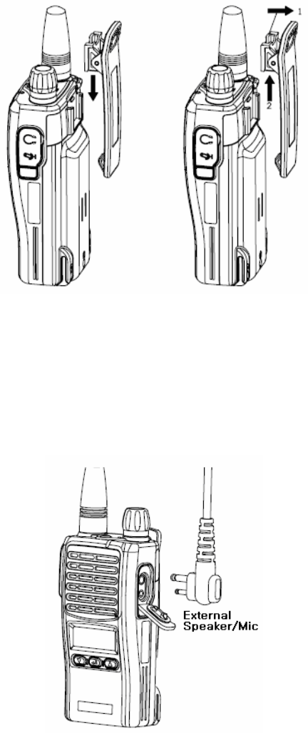
4.3 Installation and Removing the Belt Clip
- To attach belt clip to radio, align belt clip rails with the grooves in radio and slide the belt clip
onto the mounting rails until it latches into place.
- To remove belt clip from radio, push up on tab of belt clip with flat bladed screwdriver and at
the same time, slide the belt clip towards the top of Radio (Figure4-3).
Figure 4-3) Installation and Removing the Belt Clip
4.4 Accessory connector
Accessory connector is used to connect manufacturer approved accessories such as external
speaker/Mic, and headset.
Please close the cover when nothing is connected.
Figure 4-4) Accessory connector

11
5. Operating XU/XV-1000 RADIO
5.1 On/Off/Volume Control
Turns the radio on and off and adjusts audio volume level.
5.2 PTT Button (Push-To-Talk Button)
Radio transmission button.
5.3 Menu Button(P, Program Menu Button)
Enter into Menu mode by pressing the Menu button (P) for 2 seconds.
The sequence of menu mode is as follows allowing available functions as programmed by
manufacturer or dealer.
→ → → →
Compander → Change Group → ID → Scramble → Squelch
→ → → →
→ KEY Sound → VOX → Lone Worker → Repeater
5.4 Monitor Button(M)
The monitor mode is enabled and disabled by pressing the Monitor button (M) on the side.
Normal Mode : During pressing the (M) button for about 2 seconds, it is possible to check the
receiving status.
Continuous Mode : During pressing the (M) button for more than 2 seconds, the Radio will make a
“Beep” tone, which means the monitor function is maintained and if you press the (M) button again,
the monitor function will be released.
5.5 Emergency Button
This feature is available if operating service allows and programmed by manufacturer or dealer.
In case of emergency situation, if you press the Emergency button, a siren sound will be heard
through the speaker in the Radio and the Radio will transmit the emergency signal to the party
through the emergency channel.
5.6 Channel Buttons(▼,▲)
Channel Buttons(▼,▲) have 3 functions as shown in following.
① Channel buttons(▼,▲) are to change channels.
② Channel buttons(▼,▲) are to select menu at menu mode.
12
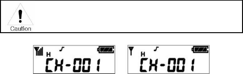
③ Channel buttons(▼,▲) are to change transmission power. By pressing Up button(▲) while
PTT button is being pressed, the user can select ”H”(High Power), or by pressing Down
button(▼), the user can select ”L”(Low Power).
5.7 Accessory Connector
The Accessory Connector is used when using an external speaker microphone or manufacturer
approved accessories and by manufacturer or dealers to configure each radio.
5.8 RX /TX Led
This LED is a lamp indicating the current status of the Radio and please refer to the below contents.
① RX : Red Lamp
② TX : Green Lamp
③ CTCSS, DCS Error : Green Blinks.
④ Low Battery: Red Blinks With “beep” sound.
5.9. Charging the Battery
5.9.1 Safety Notes
1) The radio of XV/XU series receives power from high-performance Li-ion battery
(XSB-2400). XSB-2400 Battery is safe of high performance and highly reliable, and could be
charged very fast. XSB-2400 Battery has been designed suitably only for the charger of Tekk
(WLB-1000).
The charging of the enclosed Radio on the other maker’s charger will
cause a damage on the battery and also, will cause a trouble on the
Radio.
Please charge the battery before using the radio for best performance and safety.
2) When you charge the battery that is installed in the Radio, please turn off the radio first to charge
the battery.
3)
The continuous rapid discharge (for example, when making a short circuit
on the ‘+’ terminal of battery by a metal substance) may make a fatal defect
and the battery can be exploded. Also, it can cause a fire.
4) Using the correct battery will improve the efficiency and safety.

13
5.9.2 The Time of Charging
Low battery voltage will make the radio less coverage and also make the performance worse.
Please charge the battery in case of following:
① When you think performance of the radio becomes lower
② When the red lamp on RX/TX Led blinks (every 0.5 second) during transmission or
reception
③ When the battery icon blinks
4) When “beep” sound is generated while the radio is in use.
Figure 5-1) Charging the Battery
5.9.3 How to Charge
1) Plug the DC-1000 charger into the electricity power outlet.
2) When charging the Radio with the battery installed, please turn off the power of the Radio
and place the Radio on the charger (The charger has a slide slot.).
3) After completion of the charging, the green LED on the charger will light. However, please
continue the charging for 30 more minutes for the complete full charge.
status LED indication status LED indication
During charging Red LED lights. Detecting error Red LED is off.
After charging Green LED lights. When charging Green LED lights
14
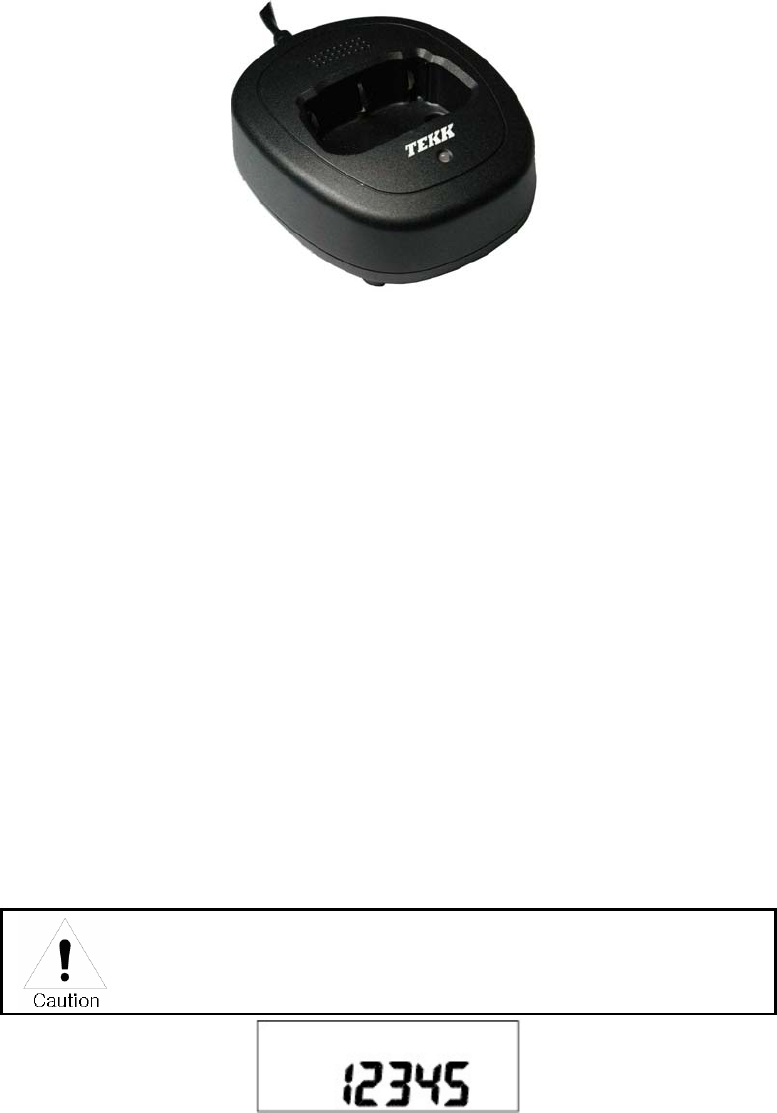
5.9. 4 Charger (XDC-1000)
The DC-1000 charger is designed to charge only the Li-ion battery enclosed in this Radio.
Figure 5-2) XDC-1000 Charger
Specifications of XDC-1000 Charger :
• Input Voltage : DC85 ~ 250V
• Battery : XSB-2400
• Quick Changing Tume : In 4Hours and half
• Operation Temperature : 0℃~+50℃
• Size : 90(W)x105(D)x37(H)m/m
• Charging Current : 850mA(Fast charging)
6. Operating Instructions of XV/XU-1000 Radio
6.1 Power On/Off
Turn Power switch clockwise. As soon as power is supplied, the backlight will be turned on.
If the user had set up the user ID, it will be displayed on the LCD and radio will enter into the latest
state as a signal sound is generated.
When turning (power) on the radio by pressing a button on it, the radio may
enter into a special mode in which transmission and reception is
impossible. Please don’t turn on the radio by above way.
Figure 6-1) User ID
15
6.2 Transmission Method
For transmission, press PTT button on the left side of the radio. As soon as the user presses
keys according to the setting, DTMF or 5-tone ID will be transmitted, and during this time,
voice communication will be interrupted for several seconds. Then, red LEDs for transmission
and reception will be turned on. It is recommended to talk 5 ~ 10cm away from the microphone
for the best voice communication.
.
☞ Note: If the user makes transmission for more than a certain time while BCLO or TOT
feature is on, transmission will be forcefully disconnected for other users.
If present channel is TX Inhibited by programming, TX will not be worked.
figure 6-2) When receiving figure 6-3) When transmitting
6.3 Reception Method
The user should not press PTT button during the reception. The user can adjust the volume by
Volume switch, and during reception, the green LED will be turned on. Depending on conditions of
the transmitting radio,
6.4 Changing Channels
Channel buttons (▼,▲) are to change channels. Press Up button (▲). Then, “beep” sound will
be generated and the channel number will be increased. Or press Down button (▼) to
decrease the channel. If the user presses Up or Down button while only one channel is set, the
channel will not be changed and a different sound from “beep” will be generated. For fast
increase or decease channel numbers, press Channel buttons (▼,▲) for a while. In this case,
however, “beep” sound will not be generated.
16
6.5 Adjusting the Transmission Power
The user can change the transmission power – High Power or Low Power. By pressing Up
button (▲) while PTT button is being pressed, the user can select “H” (High Power), or by
pressing Down button (▼), the user can select “L” (Low Power). By selecting Low power under
good communication conditions, the user can extend the battery use time.
Figure 6-4) High Power Figure 6-5) Low Power
6.6 Operation of Scan function
(Optional feature depending on operating service and radio programming)
By pressing Menu Button (P) and Enter Button ( ) in order within 0.5 second in Standby mode,
the user can activate Scan function. After Scan function is activated, the radio will
automatically search channels and detect a channel corresponding to the frequency. To
deactivate Scan function, press Menu Button (P) once.
6.6.1 Normal Scan
At the Scan mode, the LCD displays ‘SCAN’ icon. When the scan list is S1, S2, S3, the Radio
proceeds the channel scan in the sequence of S1, S2, S3, S1, S2, …. During receiving a
signal, if you press the UP(▲) or DOWN (▼) button, you can delete the receiving channel
temporarily from the scan list and at that time, you can move to the next channel.
6.6.2 Priority Scan
At the Priority Scan mode, the LCD displays ‘SCAN’ and ‘P-‘ icons. The Radio scans the
channel in the sequence of P, S1, P, S2, P, S3, … at the priority scan mode. During receiving
signal through the common channel, the Radio scans the priority channel periodically and if
the Radio detects the Priority channel, it starts receiving the channel. During receiving the
signal, you can move to the following scan channel by pressing the UP or DOWN button. If you

17
press the Enter button, you can erase the current receiving channel temporarily from the scan
list and at that time, you can move to the next channel.
But in the course of receiving the Priority channel signal, you can not change or erase
the channel by the UP/DOWN buttons(▲,▼).
6.7 Key Lock function
During pressing the “Enter” button at the receiving standby mode, press the "▲" button within
0.5second and then, the Key Lock function will be executed and the key icon of LCD will appear. At
this situation, the other key except for the PTT and the Monitor key will not be operated. In order to
release the Lock function, press the " Enter " button and during pressing the button, press the "▼"
button within 0.5second.
6.8 2TONE / 5TONE function
(Optional depending on operating service and radio programming)
6.8.1 2TONE
You can use the private and group tone functions by the central control system which is using the
2TONE SIGNALLING. If the Radio receives the tone signal, the Radio will make a Beep sound
which is advising the tone signal status and which means the Radio is ready to talk.
6.8.2 5TONE
At the tone mode, you can make the private & group calls by the 5TONE and each call memory
has the call IDs up to 30 numbers. The set-up of call memory and 5-TONE is made by PC
programming. If pressing the “Enter” button for 2seconds at the general mode, the Radio is
converted to the call mode and if pressing the "P(Program-MENU)" button for 2seconds at the call
mode, the Radio is converted to the general mode. By using the channel buttons (▲,▼) at the call
mode, the call number of a channel which is available for the call is displayed.
Figure 6-6) General Mode Figure 6-7) Call Mode
1) 1:1 Call at call mode
Press the “Enter” button for a long period(about 2seconds) at the general mode in order to
enter into the call mode.
18
① Select your party to call by using the channel button (▲, ▼). If you ( ID : 12345 ) want to call
your party(ID : 54321), select him(ID : 54321) by using the channel button
(▲,▼) at the call mode.
Figure 6-8) ID Selection
② You can call the party (ID : 54321) by pressing the “Enter” button and then, the Radio of
your party(ID:54321) displays the ID number "12345". Even though your party’s Radio is in
general mode, the Radio will be converted to the call mode automatically.
Ffigure 6-9) ID Transmission
③ After the call is completed, the Transmission and the Reception have no restriction,
which means that the TX/RX will be free.
2) 2) Group(1:N) Call at call mode
① In order to make the Group call at the call mode, the following should be set up at the PC
programming.
② If the 1st party (ID:53579) and the 2nd party(ID:52468) are in one group, the "5AAAA"which
is a call number / call name(example : baseball player) should be designated. ("A" means
that all the numbers are applied.)
3) If the caller makes a call to the group of baseball players, the caller’s Radio should press the
“Menu” and “▲” buttons at the same time after selecting the party with ID “1AAAA”. In this
case, the Radios of the party1 and the party2 display the ID "1AAAA". In case of the group
call, the party’s Radio displays the group ID number.
After the call is completed, the Transmission and the Reception have no restriction, which
means that the TX/RX will be free.
Figure 6-10) Group Call

19
3) RESET
This Reset function converts the TX/RX with no restriction to the previous Close mode. Press the
Monitor button (M) at the call mode.
① The call signal will be transmitted to the party’s Radio with the ID number + “C” tone.
② If the party’s Radio is in the Close channel and after receiving the call with the “C” tone, the
call is converted to the “TX/RX with no restriction” mode.
6.9 Emergency Call function
(Optional depending on operating service and radio programming)
1) This Emergency call is used for calling the party in emergency and if pressing for about 2
seconds the button in Red color on the top side of Radio, the Emergency Call is transmitted.
In case of setting to the emergency call channel (available by PC programming) with your ID at
the general mode or if the Radio is in the call mode, you can make an Emergency Call by
pressing the button in Red color for about 2 seconds.
The transmission is sent with the “C” tone after your ID number.
① The party’s Radio receives the “C” tone along with your ID number. The Radio recognizes it
as an emergency call and displays your ID number with the consecutive alarm sound.
2) Without transmitting the emergency call to the party, the Radio itself makes the emergency call
sound continuously.
6.10 STUN function
(Optional depending on operating service and radio programming)
The Radio is lost or in case you don’t want someone to use your Radio, the reception of STUN ID
saved in the Radio protects the Radio from the use by someone.
(The Stun ID can be set up by PC Program.) If the STUN ID is saved in the Radio, the Radio can’t
be used even after the power off & on of Radio. After receiving the UNSTUN ID, you can use the
Radio.
Figure 6-11) STUN Screen

20
6.11 Programming function available to manufacturer and dealer
The Programming is the function for input of the data such as Frequency/Tone/Scan
into the Radio.
* Programming Method
First, please prepare the Program cable for XP-Series Radio.
① Press the “P” button of the Radio to turn on. Then, the –Prog- message is
displayed.
② Connect the Programming cable to the Ear/Microphone Jack of Radio.
③ By using the PC Program, store the data and after disconnecting the cable, turn off the
power and turn on the power again.
Figure 6-12) Program Screen
6.12 Cloning function available to manufacturer and dealer
The CLONING is to copy the data such as Frequency/Tone/Scan into the other Radio.
* Cloning Method
① First, please prepare the Clone cable for XP-Series Radio.
② The original Radio should be turned on with pressing the PTT button and the Radio
to be copied should be turned on with pressing the “ P “ button .
③ The original Radio displays –CLON- message, and the Radio to be copied displays
–Prog- message.
④ Connect the Clon cable to the Ear/Mic Jack of 2 Radios.
⑤ If pressing the "Enter" button of the original Radio, the copy is made and after completing,
please disconnect the cable and turn off & on the power of the 2 Radios. Finally please use
the Radio after checking if the copy is made without problem.
☞Caution) If the Cloning is made into the other brand’s Radio, a malfunction can happen.
Figure 6-13) CLON Screen
21
6.13 Menu description
(Optional depending on operating service and radio programming)
If pressing the "P" button on the side for 2 seconds, the Radio will be in Menu mode. The Menu
mode consists of 9 Menus and you can use your desired Menu after selection.
☞ Caution) After entering into the Menu, if you don’t operate the Menu for more than 8 seconds,
the Menu mode will be terminated automatically and it is converted to the Receiving mode.
6.13.1 Compander selection
(Optional depending on operating service and radio programming)
This Compander selection is for On/Off of the Compander.
The selection can be made by the PC program and at the Menu.
① Enter into the Menu mode.
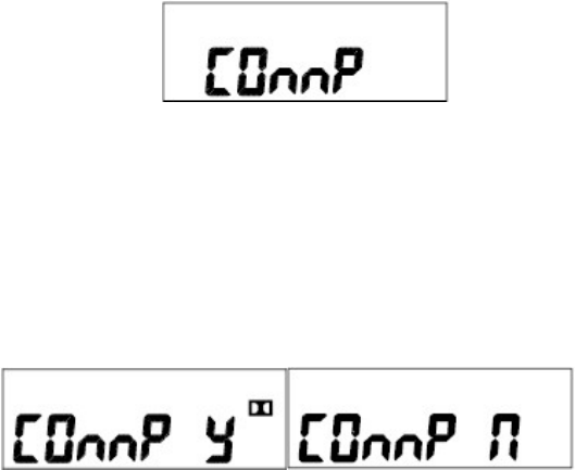
② By using the channel button(▲, ▼), choose the "Comp" and press the "Enter" button.
Figure 6-14) Compander Screen
③ By using the channel button(▲,▼), choose the ON(”y") or the OFF(“n”) and press the “Enter”
button to store.
④ In order to come out of the Menu mode, press the “P” button and by selecting the On/Off,
the Compander ICON on LCD disappears/appears.
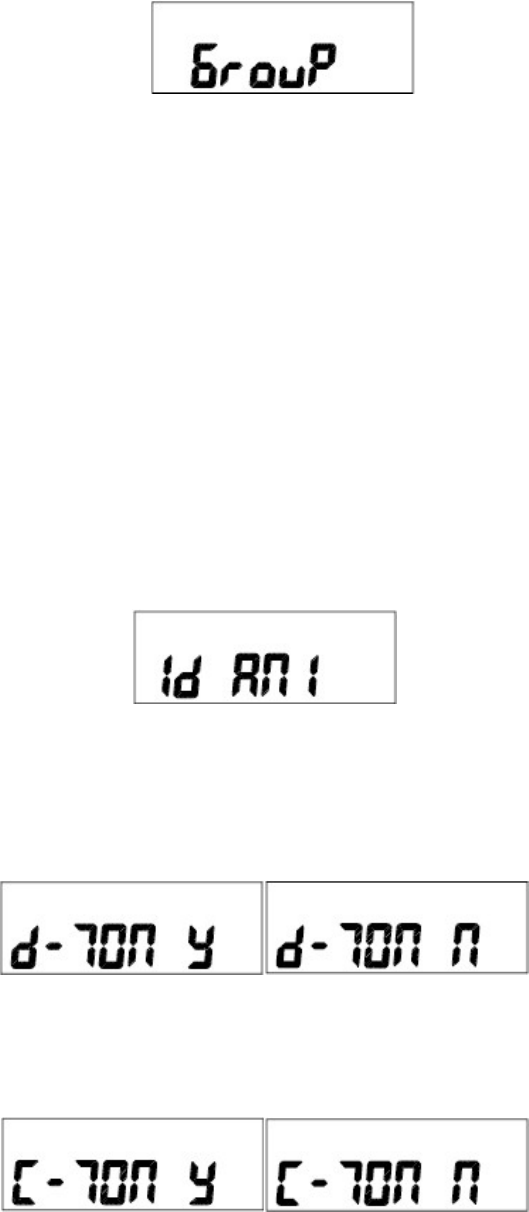
6.13.2 Group change
The Radio is designed to have total 512 channels and 16 Groups and the selection of each Group
& Channel can be available by PC program and Menu.
① Enter into the Menu mode.
② By using the channel button(▲, ▼), choose the "Group" and press the "Enter" button.
22
Figure 6-15) Group Screen
③ Using the channel button(▲,▼), choose the Group and press the “Enter” button
to store.
④ In order to come out of the Menu mode, press the “P” button.
6.13.3 ID output
(Optional depending on operating service and radio programming)
This is for transmission of your ID and reception of your party’s ID. ID is divided by DTMF and Call
ID. Especially the Call ID transmits your ID to the party and also, the party’s ID is displayed on your
Radio to use your Radio in convenience and efficiently.
① Choose the "Id ANI" by the channel button and press the " Enter " button.
Figure 6-16) ANI Screen
② After the “d-TON” message comes out, choose the ON(”y")/OFF(“n”) by the channel
button and press the “Enter” button.
③ After the“C-TON” message comes out, choose the ON(”y")/OFF(“n”) by the channel button
and press the “Enter” button.
④ Comes out of the Menu mode by pressing the “P” button.
23
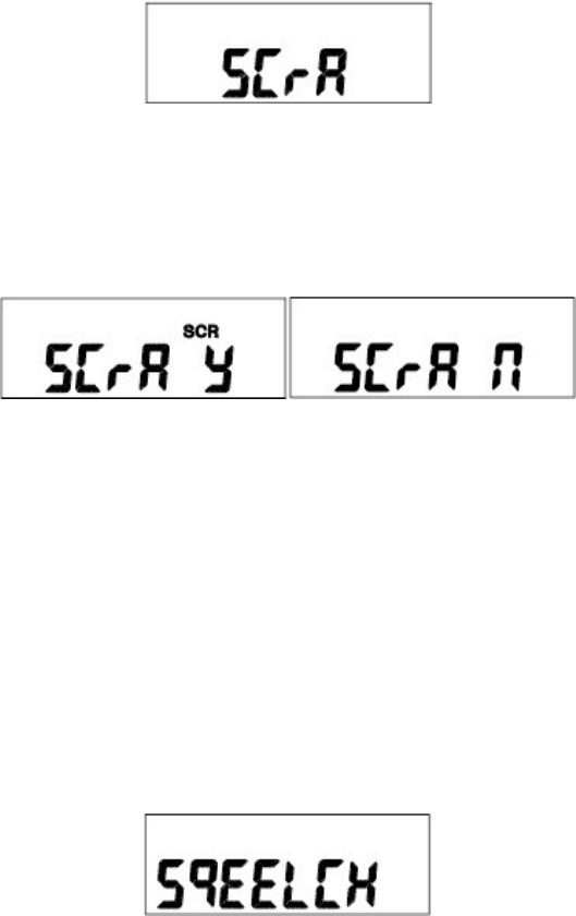
6.13.4 Scramble selection
(Optional depending on operating service and radio programming)
The Scramble is for protection from overhearing and the scramble reverses the voice signal from
microphone to a specific frequency and a mixed voice in order for the other person not to hear your
voice.
The selection can be available by PC program and Menu.
① Enter into Menu mode.
② Select “SCrA” by pressing Channel buttons (▼,▲), and press Enter button( )..
Figure 6-17) Scramble Screen
③ Select On(y) or Off (n) by pressing Channel buttons (▼,▲), and save the selected status by
pressing Enter button( )..
④ Exit Menu mode by pressing Menu Button(P) button. Select “Off”. Then, the “ SCR
“ symbol will disappear on the LCD
6.13.5 Set Squelch
Squelch sensitivity level is selectable by 5step.
By PC Program and menu, it could be set.
1. Enter into Menu mode.
2. Select “SQUELCH” by pressing Channel buttons (▼, ▲), and press Enter button( ).
Then, the message of the squelch sensitivity will be displayed.
.
Figure 6-18) Squelch Screen
24
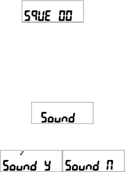
3. Select squelch sensitivity -0~5- by pressing Channel buttons (▼, ▲), and press Enter
button( ) to save the level
.
4. Exit Menu mode by pressing Menu Button(P).
6.13.6 Set KEY Sound
Set Key Sound menu is to decide whether to generate sound or not when the user presses four
buttons .
By PC Program and menu, it could be set.
1. Enter into Menu mode.
2. Select “Sound” by pressing Channel buttons (▼,▲), and press Enter button( ). .
Figure 6-19) Key Sound Screen
3. Select On(y) or Off (n) by pressing Channel buttons (▼,▲), and save the selected status by
pressing Enter button( ).
4. Exit Menu mode by pressing Menu Button(P) button. Select “Off”. Then, the “ “ symbol
will disappear on the LCD.
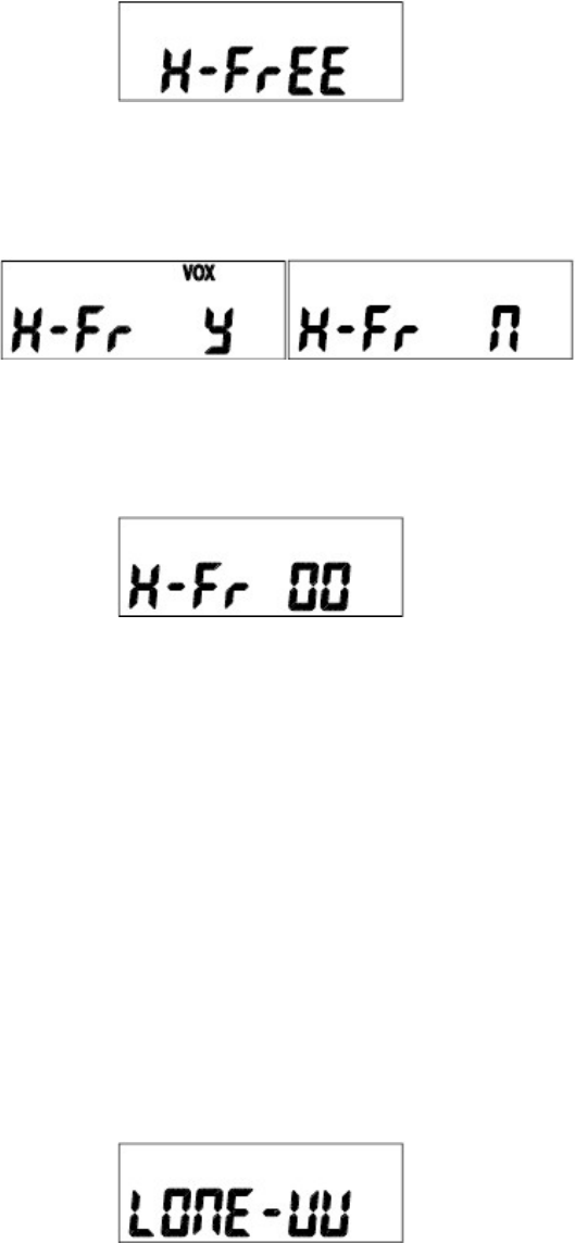
6.13.7 Set VOX
Set VOX is to enable users to make transmission for VOX without pressing PTT button. (This
function could be available with Ear Mic [External VOX]).
By PC Program and menu, it could be set.
1. Enter into Menu mode.
2. Select “H-FrEE” by pressing Channel buttons (▼,▲), and press Enter button( ).
25
Figure 6-20) VOX Screen
3. Select On(y) or Off (n) by pressing Channel buttons (▼,▲), and press Enter button( )
.
4. Select on(y). Then, the “vox , H-Fr 05“ symbol s will appear on the LCD.
Set sensitivity by pressing Channel buttons (▼,▲), and press Enter button( ).
5. Select “Off”. Then, the “ vox “ symbol will disappear on the LCD.
6. Exit Menu mode by pressing Menu Button(P) button.
6.13.8 Set Lone Worker
(Optional depending on operating service and radio programming)
The Set Lone Worker is for transmission of emergency alarm sound without pressing the
designated button within a period of time when night patrol or guarding and the Lone Worker can
be set to be ON/OFF.
The selection can be available by PC program and Menu.
1. Enter into Menu mode.
2. Select “LONE W” by pressing Channel buttons (▼,▲), and press Enter button( ).
Figure 6-21) Lone Worker Screen
3. Select On(y) or Off (n) by pressing Channel buttons (▼,▲), and save the selected status by
pressing Enter button( )..
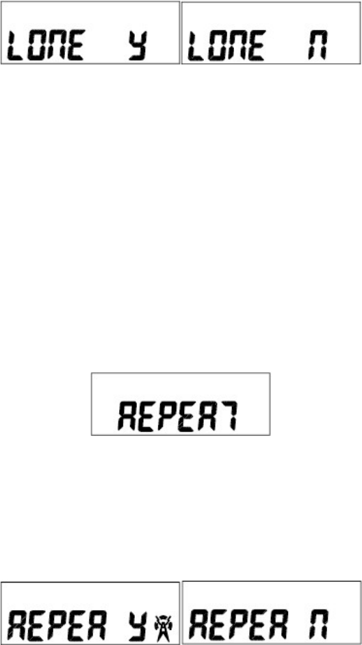
26
4. Exit Menu mode by pressing Menu Button(P) button.
6.13.9 Set Repeater
(Optional depending on operating service and radio programming)
If you want to use the XP Series Radio as a repeater, you can operate the Repeater by
On / Off.
The Repeater function should be set up by PC program and if not, at the Menu mode the Repeater
set-up is not shown.
1. Enter into Menu mode.
2. Select “REPEAT” by pressing Channel buttons (▼,▲), and press Enter button( ).
Figure 6-22) Repeater Screen
3. Select On(y) or Off (n) by pressing Channel buttons (▼,▲), and save the selected status by
pressing Enter button( )..
4. Exit Menu mode by pressing Menu Button (P). Select “Off”. Then, the “ “ symbol will
disappear on t he LCD

27
6.14 Sub-Tone Table
1) TCSS Frequency Table
No. Frequency No. Frequency No Frequency No. Frequency
1 67.0 14 107.2 27 167.9 40 159.8
2 71.9 15 110.9 28 173.8 41 183.5
3 74.4 16 114.8 29 179.9 42 189.9
4 77.0 17 118.8 30 186.2 43 196.6
5 79.7 18 123.0 31 192.8 44 199.5
6 82.5 19 127.3 32 203.5 45 206.5
7 85.4 20 131.8 33 210.7 46 229.1
8 88.5 21 136.5 34 218.1 47 254.1
9 91.5 22 141.3 35 225.7 48 165.5
10 94.8 23 146.2 36 233.6 49 171.3
11 97.4 24 151.4 37 241.8 50 177.3
12 100.0 25 156.7 38 250.3 51 60.7
13 103.5 26 162.2 39 69.3 52 62.5

28
2) DCS Tone Table
No. DCS Code No. DCS Code No. DCS Code No. DCS Code
1 023 28 172 55 431 82 743
2 025 29 174 56 432 83 754
3 026 30 205 57 445 84 053
4 031 31 223 58 464 85 122
5 032 32 226 59 465 86 036
6 043 33 243 60 466 87 14
7 047 34 244 61 503 88 212
8 051 35 245 62 506 89 225
9 054 36 251 63 516 90 246
10 065 37 261 64 532 91 252
11 071 38 263 65 546 92 255
12 072 39 265 66 565 93 266
13 073 40 271 67 606 94 274
14 074 41 306 68 612 95 325
15 114 42 311 69 624 96 332
16 115 43 315 70 627 97 356
17 116 44 331 71 631 98 446
18 125 45 343 72 632 99 452
19 131 46 346 73 654 100 454
20 132 47 351 74 662 101 455
21 134 48 364 75 664 102 462
22 143 49 365 76 703 103 523
23 152 50 371 77 712 104 526
24 155 51 411 78 723
25 156 52 412 79 731
26 162 53 413 80 732
27 165 54 423 81 734
29
7. Precautions
7.1 When using the XP Series Radios
Don’t remove the antenna from the Radio or don’t transform the antenna or don’t
make any change on the antenna. The strong electronic wave to be emitted from
the Radio can have an effect on the performance of the Radio and can cause the
Radio to have a defect.
Don’t use the accessories (such as rechargeable battery, adaptor, external
speaker microphone and earphone, etc.) from the other makers, which can
cause to make a defect on battery and a malfunction or a defect on the Radio.
Don’t disassemble or reorganize the Radio. The disassembly or reorganization
will be causes of defect or malfunction and it will be impossible to make repair
afterward. Also, a punishment can be made by law.
Don’t use the other frequency except for the permitted frequency in order not to
be punished by law.
• Don’t give an excessive shock to the Radio.
• Don’t place the Radio where the direct sunlight and/or the high temperature
occurs.
• If the Radio is placed for a long time in car in summer, the hot temperature in
the car may cause an explosion of battery.
• Don’t make a damage to the battery by a sharp substance and/or an
excessive shock.
30
7.2 Influences to the operations of Radio or other Equipments
The Radio emits a strong electronic wave, which may have an effect on the operation of other
equipments and also, can be influenced by the other devices.
Please turn off the Radio before boarding on airplane.
When you want to use the Radio in the airplane, please follow the rules in the
airplane or the instructions by crew.
In case of the area that medical equipments are being used, please use the
Radio after discussion with the equipment maker or the related doctor.
Please don’t use the Radio at the place where computer or the other
electric/electronic devices are being used, because the strong electronic wave
from the Radio can have an effect on the equipments.
8. Safety Notes
Please make sure to read the followings for safe and effective use of the Radio.
Please keep the Radio away at least 1inch from the body.
If the outside surface of antenna gets stripped out, it can make a burn on the
skin.
Please turn off the Radio before boarding on airplane.
When you want to use the Radio in the airplane, please follow the rules in the
airplane or the instructions by crew.
31
If you contact a conductive metal to battery terminal, a heat can be made and it
may cause fire, explosion and burn. Especially, please be careful when putting
the battery in a pocket or a bag.
When using an earphone, please don’t listen to the sound at a high level. The
high sound may have a bad effect on your ear.
After setting the volume of the Radio at a low level, please adjust the volume
step by step to the level you want. A sudden high sound may give a bad
damage to the ear or the heart.
Please don’t remove or replace or charge or discharge the battery at a
dangerous area, since it may cause an explosion or a fire by an electrical
spark.
At the area where an electromagnetic force can be made, please make sure to
turn off the power of the Radio.
FCC Information
THIS DEVICE COMPLIES WITH PART 15 OF THE FCC RULES. OPERATION IS SUBJECT TO
THE CONDITION THAT THIS DEVICE DOS NOT CAUSE HARMFUL INTERFERENCE.
MODIFICATIONS OR CHANGES NOT EXPRESSLY APPROVED BY THE MANUFACTURER
COULD VOID THE USER’S AUTHORITY TO OPERATE THE EQUIPMENT.
IMPORTANT NOTE: To maintain compliance with Radio Frequency exposure guidelines,
hold the transmitter and antenna at least 1 inch (2.5 centimeters) from your face. If you
wear, the handset on your body while using the approved accessories, use only the
manufacturers supplied belt clip for this product and ensure that the antenna is at least
1.5 centimeters from your body when transmitting.
Your radio generates radio frequency electromagnetic energy during transmission mode. The radio is
designed for and classified as “Occupational Use Only” and must be used by individuals who are properly
trained and aware of these hazards and the means in which to minimize such hazards. This radio is NOT
32
intended for use by the “General Population” or in uncontrolled environments.
To ensure that your exposure to radio frequency electromagnetic energy is within the FCC allowable limits
for occupational use, always follow these guidelines:
DO NOT transmit for more than 50% of the total radio use time (this is a maximum 50% duty cycle radio).
Transmitting more than 50% can cause FCC RF exposure compliance requirements to be exceeded.
Pressing the PTT switch enables the radio to transmit. Use ONLY authorized accessories with this
equipment. Use of unauthorized accessories can cause the Radio Frequency Exposure compliance
requirements to be exceeded.
9. Specification
9.1 XV-1000
General
Frequency Range
Frequency Stability
Programmable Channels
Channel Spacing
Dimensions
Weight
Power Source
Current Drain (maximum)
Duty Cycle(5/5/90)
VHF: 136 ~ 174 MHz
±2.5PPM (-30 to +60℃)
256 Channels/16 Group
Dual Channel Spacing 12.5/25 KHz
111mm (H)×54mm (W)×37mm (D)
347g (with Battery pack & Antenna)
DC +7.5V rechargeable Li-ion 2400㎃H battery pack
Receive mode, rated audio out - 320㎃ (Audio Max)
Transmit mode – 1,600㎃(High), 900㎃(Low)
Standby mode - 60㎃H
15.5 Hours(High) / 21 Hours(Low)
Receiver
Sensitivity
Squelch Sensitivity
Selectivity
Spurious and Harmonic Rejection
Inter-modulation
FM Hum and Noise
Audio Output Power
Audio Distortion
Audio Response
Speaker Impedance
.282uV 12 dB SINAD
.25uV 10dB SINAD
65dB (12.5KHz), 70dB (25KHz)
70dB
65dB (12.5KHz), 70dB (25KHz)
40dB (12.5KHz), 45dB (25KHz)
1 Watt across an 16-ohm load
Less than 5% at rated output
+1, -3 dB from 6dB per octave de-emphasis Characteristic
from 300 ~ 3000Hz
16 ohms
33
IF Frequencies
Input Impedance
21.4MHz and 455KHz
50 ohms
Transmitter
RF Power Output
Spurious and Harmonic
FM Hum and Noise
Audio Distortion
Audio Frequency Response
Output Impedance
5/2Watt
70dB
40dB (12.5KHz), 45dB (25KHz)
5% maximum with 1KHz modulation
+1, -3dB from 6dB per octave pre-emphasis Characteristic
from 300 ~ 3000Hz
50 ohms
9.2 XU-1000
General
Frequency Range
Frequency Stability
Programmable Channels
Channel Spacing
Dimensions
Weight
Power Source
Current Drain (maximum)
Duty Cycle(5/5/90)
UHF: 405 ~ 475 MHz
±2.5PPM (-30 to +60℃)
256 Channels/16 Group
Dual Channel Spacing 12.5/25 KHz
103mm (H)×52mm (W)×32mm (D)
347g (with Battery pack & Antenna)
DC +7.45V rechargeable Li-ion 2400㎃H battery pack
Receive mode, rated audio out - 320㎃ (Audio Max)
Transmit mode – 1700mA(High), 1,000mA(Low)
Standby mode - 60mA
15 Hours(High) / 20 Hours(Low)
34
Receiver
Sensitivity
Squelch Sensitivity
Selectivity
Spurious and Harmonic Rejection
Inter-modulation
FM Hum and Noise
Audio Output Power
Audio Distortion
Audio Response
Speaker Impedance
IF Frequencies
Input Impedance
.282uV 12 dB SINAD
.25uV 10dB SINAD
65dB (12.5KHz), 70dB (25KHz)
70dB
65dB (12.5KHz), 70dB (25KHz)
40dB (12.5KHz), 45dB (25KHz)
1 Watt across an 16-ohm load
Less than 5% at rated output
+1, -3 dB from 6dB per octave de-emphasis Characteristic
from 300 ~ 3000Hz
16 ohms
45.3MHz and 455KHz
50 ohms
Transmitter
RF Power Output
Spurious and Harmonic
FM Hum and Noise
Audio Distortion
Audio Frequency Response
Output Impedance
4/2Watt
65dB
40dB (12.5KHz), 45dB (25KHz)
5% maximum with 1KHz modulation
+1, -3dB from 6dB per octave pre-emphasis Characteristic
from 300 ~ 3000Hz
50 ohms