Tektron Micro Electronics DST1000 DIGITAL STEREO TRANSMITTER User Manual DST1000 TxManual
Tektron Micro Electronics Inc DIGITAL STEREO TRANSMITTER DST1000 TxManual
USERS MANUAL
1
1.0 INTRODUCTION.
1
1.1 THE DST1000 DIGITAL STEREO TRANSMITTER.
The DST1000 is a digital wireless stereo transmitter, which offers extremely high
quality audio response. It provides input for two electret microphones, and uses a
stereo analog-to-digital converter and a digital RF operating at selected UHF
frequencies. Because the radio transmission is truly digital in nature, a companion
Tektron digital receiver (the DSR1000) delivers audio signals, which are nearly
indistinguishable from a hard-wire connection to the DST1000 microphones.
The unique characteristics of this transmitter also contribute to a simple and user-
friendly operating environment. These include: dual channels of information
transmitted from a single antenna, two microphones cables, and a power cable. The
user has flexibility to use a preferred microphone style and has considerable leeway
in using a power source fitting a variety of operational requirements regarding size,
type and duration
2
1.1.1 THE DST1000 SUMMARY OF FEATURES.
- Two 16 bit channels, 40 Hz to 16 KHz bandwidth.
- 90 dB dynamic range with 0.01% distortion, exclusive of microphones.
- Wide dynamic range obtained without AGC.
- Forward Error Correction included.
- External microphones on attached 18-inch cables.
- Power cable.
- Fully enclosed metal case.
- 1.68” x 2.12” x 0.165” overall size.
- SSMC antenna connector (flexible antenna supplied).
- 1000 mW or 500 mW output power, user select.
- Multi-channel.
- <2.5 ounces total weight.
3
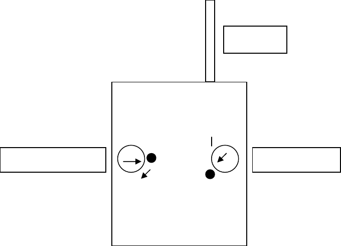
1.1.2 TRANSMIT POWER AND CHANNEL SELECT SWITCHES.
Figure 1. Location of the Channel and Power Select Switches on the
DST1000 Chassis.
The black dot at the channel select switch indicates the position of the lowest channel
frequency. The channel frequency is incremented by turning the switch in the
clockwise direction. One end of the slot in both the channel select and the power select
switch has two markers: this end is represented as the head of the arrow in Figure 1.
The black dot at the power select switch indicates that the transmitter is operating at 1
Watt output power. Turning the switch to the dash line reduces the output power to 0.5
Watt.
Antenna
Channel Switch Power Switch
4
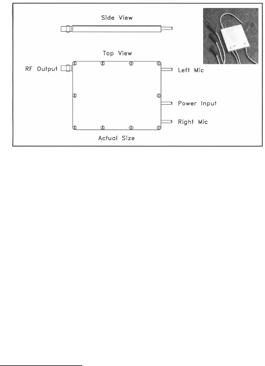
1.2 THE DST1000 CONNECTOR NOMENCLATURE.
An SSMC male connector is used for the antenna. The AEP mating antenna
connector is part no. 7002-1541-010.
AEP connectors are available from:
Applied Engineering Products
104 John W. Murphy Drive
New Haven, CT 06513
Telephone: 1-800-444-5366
1.3 DST1000 PACKING LIST.
1 each DST1000 Digital Stereo Transmitter Serial No.
1 each DST1000 Antenna.
1 each DST1000 Operating Manual.
5
2.0 DST1000 SPECIFICATIONS.
All performance specifications are typical at +250C, unless otherwise noted.
Audio Channels 2 (left/right stereo)
Microphones External electret required (not supplied)
Microphone Power 1.8 VDC @ 50 uA
Analog S/N Ratio 86 dB (max. input to "A" weighted noise) *
Total Harmonic Distortion 0.01% (max. input @ 1 KHz) *
Audio Frequency Response 40 Hz to 16 KHz, @ -6 dB *
200 Hz to 15 KHz, +.5/-.5 dB *
Stereo Separation 80 dB (40 Hz to 16 KHz) *
Audio Gain 30 dB (microphone input to receiver output)*
* Exclusive of microphone, measured at Tektron
digital receiver analog output.
Digitization 16 bit Linear Sigma-Delta A/D Conversion
Anti-Alias Filter Linear Phase Digital Filter
0.01 dB Passband Ripple, 80 dB Stopband Atten.
Sampling Rate 32 KHz
Sampling Accuracy +/- 50 ppm, -10 to +500 C
Information Rate 1.024 MBit/second
Coding Rate 1/2 Forward Error Correction
Signaling Rate 2.048 MBit/second
6
2.0 DST1000 SPECIFICATIONS (Continued).
Transmission Frequency 8-Channel, selectable (contact factory
for frequency options).
FCC certified 902-928MHz
Frequency Stability +/- 0.05%, -10 to +500 C
Modulation Minimum Shift Keying
RF Spectrum Evenly distributed about channel center
RF Bandwidth 2 MHz @ 10 dB below peak density
Power Output 1000 mW into 50 ohm load @ 5.5-14 VDC
500 mW into 50 ohm load @ 4-14VDC
Antenna Impedance 50 ohms (less than 5:1 VSWR)
Antenna Whip supplied
Antenna Connector SSMC Jack (male)
External Power 4.0 to 14 VDC negative ground
DC to RF Efficiency >50%
Operating Temperature Range -20 to +600 C
Storage Temperature Range -40 to +800 C
Size 1.68 x 2.12 x 0.165 inches
Weight less than 2.5 ounces
7
3.0 DST1000 OPERATION.
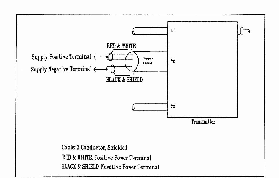
3.1 BATTERY POWER.
Power is supplied externally through the power cable. The red and white wires are
to be connected to the positive terminal of the power source, with the black and
shield wires to be connected to the negative terminal. The wiring diagram for
connecting power to the unit is presented in Figure 2.
Figure 2. Power Connection Wiring Diagram.
IMPORTANT: The DST1000 uses internally attached power and microphone
cables. DO NOT PULL ON THE CABLE.
8
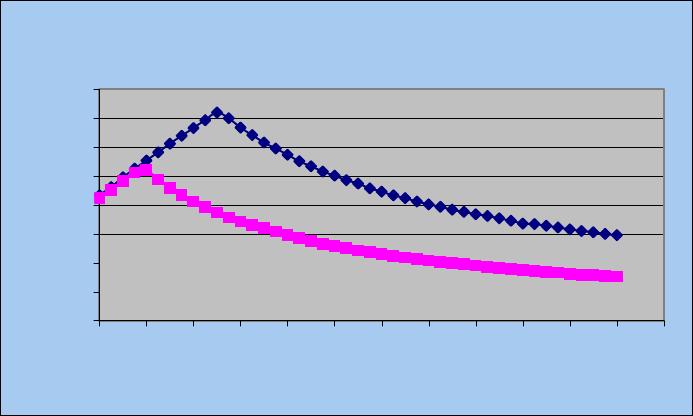
3.1.1 RF OUTPUT POWER.
The DST1000 is designed to operate over a voltage range of 4.0 – 14 VDC. The RF
output power and DC current consumption will change as the DC voltage varies.
Figure 3 charts the change in RF output power vs. DC voltage for both RF power
settings of 1000 mW and 500 mW. The minimum voltage for 1 Watt (1000 mW)
operation is 5.5V and for operation at 0.5 Watt (500 mW), 4V is required.
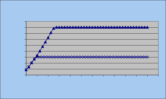
3.1.2 BATTERY CURRENT CONSUMPTION.
Figure 4 shows the relationship between current and voltage. The maximum current
is indicative of the required minimum voltage for operation at 1 Watt and 0.5 Watt.
Figure 4 shows that for operation at 1 Watt (the black graph) a minimum battery
voltage of 5.5V is required and that operation at 500 mW (the gray graph) requires a
minimum voltage of 4V. Note that after 5.5V is applied for 1 Watt operation the DC
power consumed is constant. For example at 10Vdc the current consumption is
about 200mAdc (DC Power is 2 Watts) and at 8Vdc the current consumed is
250mAdc (DC power is 2 Watts). This shows that the DC to RF efficiency is 50%
and constant above 5.5VDC for 1 Watt operation.
Figure 3 Transmit Power vs. Battery Voltage
200
300
400
500
600
700
800
900
1000
1100
3 4 5 6 7 8 9 10 11 12 13 14 15
Battery Voltage (V)
mW
9
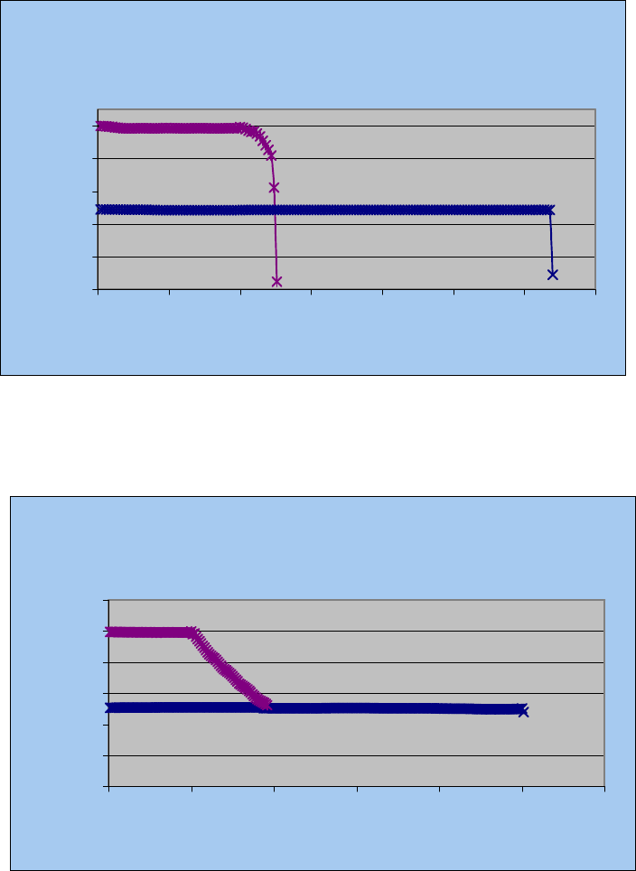
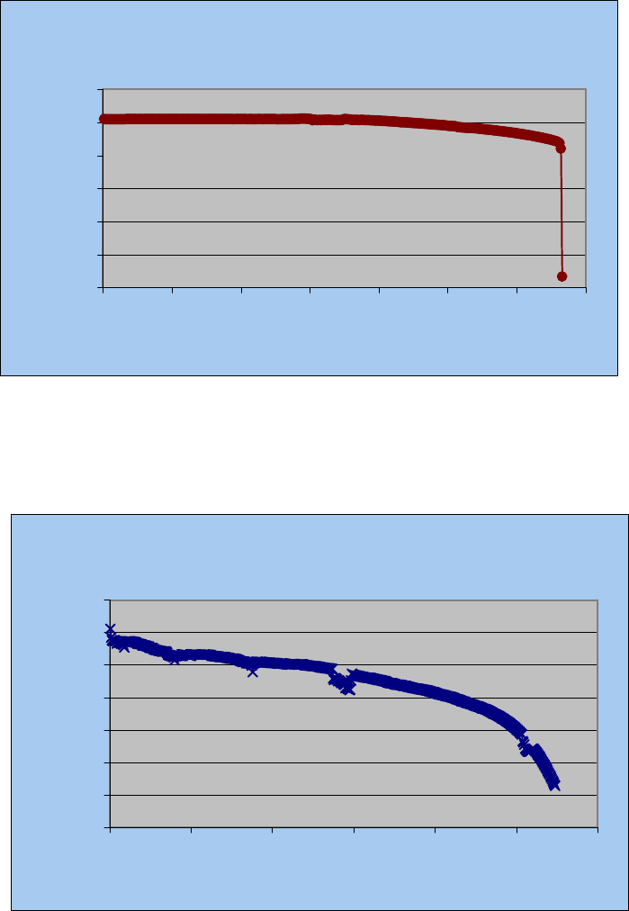
3.2 EXTERNAL POWER INPUT.
A negative ground DC supply between 4.0 and 14 volts such as a 9V alkaline or
Lithium battery is needed to operate the DST1000. Exceeding the maximum
voltage limits or failure to observe voltage polarity can cause damage to the
transmitter. Figures 5a to 5d show battery lifetime for different battery types. Figure
5a shows that one 9V alkaline battery will operate the transmitter for almost 1hour at
1 Watt and about 2.5hours at 0.5 Watt. Figure 5b shows that one 9V lithium battery
will operate the transmitter for over 4hours at 0.5 Watts. From Figure 5c, six AA
alkaline batteries will operate the transmitter for 4hours at 1 Watt. Figure 5d shows
how a 6V supply from 4 AA lithium batteries is quickly drained below the 5.5V
required to provide 1 Watt output power.
Figure 4. mA DC vs. Battery Voltage
0
50
100
150
200
250
300
350
400
3 4 5 6 7 8 9 10 11 12 13 14 15
Battery Voltage (V)
mA
10
Figure 5a Transmit Power vs. Time
9VAlkaline Battery (Energizer)
0
200
400
600
800
1000
0 25 50 75 100 125 150 175
Time (Minutes)
mW
Figure 5b Transmit Power vs. Time
9V Lithium Battery
0
200
400
600
800
1000
1200
0 50 100 150 200 250 300
Time (Minutes)
mW
11
Figure 5c Transmit Power vs. Time
9Valk_6AA (Energizer)
0
200
400
600
800
1000
1200
0 50 100 150 200 250 300 350
Time (Minutes)
mW
Figure 5d Transmit Power vs. Time
6VLi-4AA_1Watt
400
500
600
700
800
900
1000
1100
0 100 200 300 400 500 600
Time (Minutes)
mW
12
3.3 THE WHIP ANTENNA.
A properly designed antenna is important to realizing maximum power output and
range for the transmitter. The transmitter antenna connection is on the top of the
transmitter housing. Screwing on the antenna or cable connector to the matching
transmitter connector completes the antenna connection. Connections should be
finger tight, do not use wrenches or pliers to on the connector nut.
Custom antennas may be used with the DST1000. The antenna connector is a
standard SSMC female jack. The DST1000 is designed for a 50 ohm antenna load
with VSWR less than 5:1. No damage will result from short or open circuits on the
antenna jack, but it should be realized that rated power will only be delivered into a
50 ohm load.
Antenna orientation is not critical, however, several general principles should be
taken into account. When using the supplied whip antenna, standing the DST1000
vertically gives an omni-directional radiation pattern. Orienting the DST1000
horizontally will result in a “Figure-8” pattern. One situation to avoid, if possible, is
pointing the antenna directly toward the intended receiver site. This results in a
theoretical minimum amount of signal radiated toward the receiver. In practical
situations however, there will likely be enough reflections in the environment to
ensure communication with even this orientation.
For any given transmitter antenna placement, there will be some receiver antenna
orientations which will be more effective than others. When using the transmitter in
an operational setting it will be helpful to try a variety of different receiving antenna
placement and positions.
13
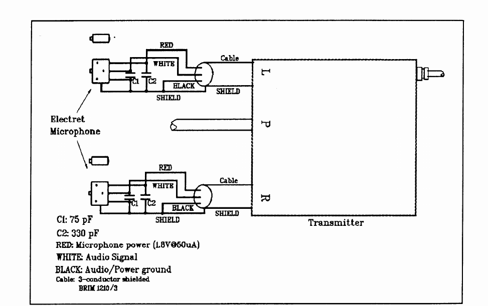
3.4 THE MICROPHONES.
Two microphones, one for each channel, must be externally connected to the
transmitter cables. The transmitter is designed to work with electret microphones
and has been tested using the Knowles electret microphones, model EK-3133. The
red lead is used to supply power to the microphones and is rated at 1.8 VDC @ 50
uA. The wiring details of how the cable is connected between the microphone and
the transmitter are shown in Figure 6.
.
Figure 6. External Microphone Wiring Diagram.
Contact the factory for microphone connections involving two wire hook-up or
microphones requiring voltage/current different from those available.
14
3.5 CHANNEL SELECTION.
The DST1000 can be manually set to operate on one of five channels. A slotted
switch is available on the top lid of the transmitter (label side). A small jeweler’s
screwdriver or plastic adjustment tool can be used to select the channel. The
transmitter label depicts the proper position of the slot to select the desired channel
(see also Section 1.1.2).
NOTE: The switch may be turned clockwise or counter-clockwise; it is only the final
position (vertical or horizontal), which determines the channel.
15
4.0 THE THEORY OF OPERATION.
Converting analog audio waveforms to digital data, that is, a sequence of rapid on-
off decisions has become almost commonplace in modern telephony, high fidelity,
and audio recording equipment. Recent advances in analog-to-digital (A/D) and
digital-to-analog (D/A) converters have made available inexpensive integrated
circuits, which allow miniaturization of all the essential functions. The primary
benefit of a digital format is that extremely accurate transmission, recording, and
reproduction becomes a reality. A secondary benefit is that the digital format lends
itself to coding and encryption in systems designed for private communications.
This section describes some details of the Tektron Digital Stereo Transmitter and the
nature of its wideband, “low probability of intercept” signal.
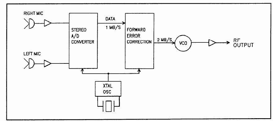
4.1 THE TRANSMITTER FUNCTIONAL BLOCKS.
Figure 7 is a simplified block diagram of a typical Tektron Digital Stereo Transmitter.
It shows the three essential functions; an analog-to-digital (A/D) converter; a
forward-error-correction (FEC) and synchronization generator; and lastly, an RF
module consisting of the oscillator, modulator and power amplifier.
…
Figure 7. The Transmitter Block Diagram.
16
The left and right microphone signals are amplified and input to a stereo analog-to-
digital (A/D) converter. The A/D converter samples each of the inputs at 32 kHz and
generators two 16-bit binary “words” which represent the instantaneous input
voltages at the moment of sampling. Because the 32 kHz sampling rate is very high
the analog input signals do not change appreciably from one sampling instant to the
next. Thus, the stream of digital output words accurately represents the input audio
signals.
Engineering textbooks give a rigorous mathematical description of this process and
show that audio frequencies as high as 1/2 the sampling rate may be conveyed by
the sampling process without ambiguity. With 32 kHz sampling rate we may,
therefore, design for an audio frequency response of 15 kHz. In fact, the A/D
converter is a large-scale integrated circuit used in high-quality Compact Disk and
digital audio applications. It employs an over-sampled “1-bit” conversion technique
and includes a sophisticated digital filter for each channel resulting in a 16 kHz
response at the 3 dB roll-off points.
Multiplying 32 kHz by 16 bits/sample by 2 channels yields the output digital date rate
of 1.024 Megabits per second (MB/s). This is applied to the digital coding and
synchronization section of the transmitter, which generates a 2.048 MB/s, coded
data output.
The 1.024 MB/s digital audio signal is converted to a 2.048 MB/s output via a rate
1/2 forward-error-correction (FEC) code. A rate 1/2 FEC means that the output data
stream has twice as many bits as the input data stream. FEC coding is a standard
technique used in digital systems to reduce the signal-to-noise (S/N) ratio required at
the receiver. Of course, more than a few errors per sample will overwhelm the
decoding algorithm but even so the final result is that the receiver requires a lower
S/N ratio with FEC coding than without.
17
NOTE: It should be emphasized that FEC coding is not the same as data
encryption used for classified message traffic. There is no message
“key” which can be changed to prevent unauthorized reception.
However, FEC coding does lend a measure of privacy in the Digital
Stereo Transmitter, in that an unauthorized receiver will have to
discover the particular algorithm used before recovery of good data is
possible. Furthermore, as described in more detail below, using both
A/D conversion and FEC coding makes it impossible for a narrow band
analog receiver to breakout the audio signal.
The final connection in the transmitter block diagram consists of the FEC coder
output link to the RF module, which generates the carrier frequency and amplifies it
to the desired power level, generally between 0.5 Watt (500 mW) and 1 Watt.
4.2 THE OUTPUT RF SPECTRUM.
The DST-series of Tektron Digital Stereo Transmitters emit a unique RF spectrum,
which is fundamentally different from that of conventional audio transmitters. It has
wideband, low-probability-of-detection characteristics which are identical to those in
costly spread-spectrum systems. This is a consequence of the inherently high data
transmission rate needed for CD quality audio combined with MSK (minimum-shift-
keying) modulation, which gives a uniform spectral density within the ratio channel.
Figures 8a and 8b are Spectrum Analyzer plots of a typical DST1000 RF output,
which illustrates this point nicely.
18
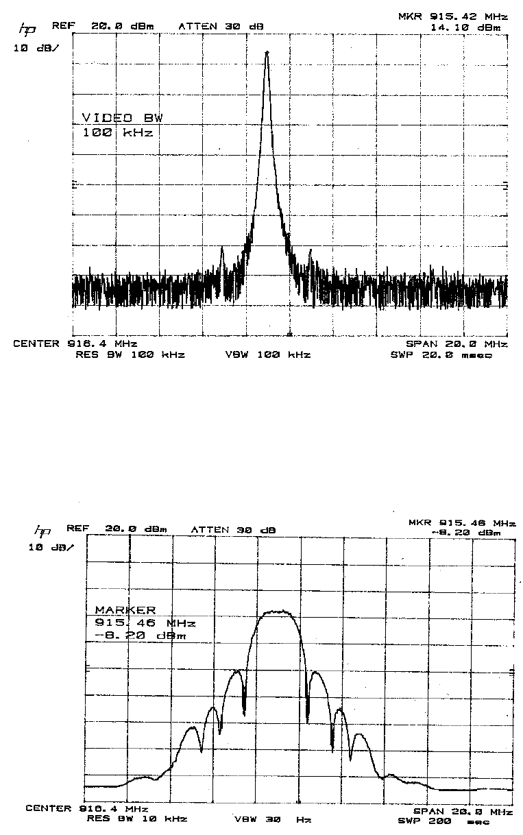
Figure 8a. RF Output Without Modulation.
Figure 8b. RF Output With Modulation Applied.
19
Figure 8a shows the transmitter signal without modulation. Accounting for a 16dB
attenuator being placed between the transmitter and the spectrum analyzer to
prevent overdriving the analyzer, it is a steady carrier at 30.0dBm (1000 mW). Note
that the analyzer shows a random noise baseline at -74 dBm when tuned off the
emitted frequency. Figure 8b shows the transmitted signal with digital modulation
and with the analyzer set for 10 kHz resolution bandwidth. (This bandwidth is typical
of commercial audio receivers and scanners, which are intended for narrowband AM
and FM reception.) Two characteristics of the DST1000 spectrum are immediately
evident. First, it is a wideband signal spread out over 2.24 MHz. Second, the
spectral density is about 5 mW in a 10 kHz bandwidth.
This occurs even though the total transmitted power has not changed! It is still 1000
mW. But now, due to the wideband modulation, the total power is spread over 200
“channels” of 10 kHz bandwidth each. A division by 200 is represented by a 23dB
reduction in power (10log10(200) = 23dB). The significance of this latter point is that
a 23dB reduction in the power measured at a scanner’s detector has been achieved,
and the likelihood of detection is correspondingly reduced. (30dBm – 23dBm =
7dBm or 5 mW). As compared with a conventional analog audio transmitter, the
DST1000 appears to be a weak, noisy signal - albeit one occupying 200 adjacent 10
kHz channels!
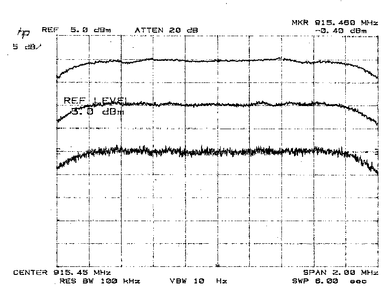
There is yet a third remarkable feature of the Digital Stereo Transmitter’s RF output
spectrum. It is that the transmitted energy is quite evenly distributed throughout the
RF channel, and that the statistics of that even-ness are unaffected by the strength
or nature of the audio signal transmitted. There are no spectral lines which wobble
and shift to reveal the underlying audio signal. Figure 9 demonstrates this fact by
expanding the spectrum analyzer display and making plots at 100 kHz (top trace),
10 kHz (middle trace), and 1 kHz (lower trace) resolution bandwidth. Note that the
measured spectral density tracks the analyzer bandwidth changes exactly, and that
there are no line spectra evident. This means there is an extremely low probability
of “breaking-out” the transmitted audio with narrowband receiving equipment.
20
Figure 9. Spectrum Analyzer Display of RF Output with different Resolution
Filter Settings.
4.3 OPERATIONAL SECURITY - LOW PROBABILITY OF DETECTION.
Operational security has become an ever-increasing problem to law enforcement
investigations as commercial scanners and walkie-talkies grow more and more
common. As a wideband, smooth-spectrum transmitter, the Tektron Digital Stereo
Transmitter provides a significant contribution to two important security
requirements; freedom to operate without detection, and privacy of message
content. This section addresses the relationship between radio wave propagation,
low spectral density and their effect on operational security.
4.3.1 RADIO WAVE PROPAGATION.
Any radio transmission creates an electromagnetic (E/M) field emanating from the
antenna. This field can be likened to a series of expanding circles of energy,
growing in diameter as they leave the point of origin.
21
As the distance between a radio transmitter and receiver increases, the received
field strength decreases geometrically in proportion to the distance covered. In free
space the field diminishes as the square of the distance. Thus, when the distance
between transmitter and receiver is doubled the field strength will reduce to ¼ (2
squared) of its previous value.
Signal propagation over ground is even more severely attenuated. At the VHF and
UHF frequencies (30 - 1500 MHz), a common estimate is that attenuation varies as
the fourth power of distance. In that case, doubling the distance between transmitter
and receiver will reduce the signal to 1/16 (2 x 2 x 2 x 2) of what it had been. The
significance of these calculations is that there is a very large difference in field
strength between the near vicinity of the transmitter and a point at the farthest
distance at which a signal can be received. Low probability of detection comes into
play, for any transmitter, when the detection device is a sufficient distance away
from the transmitter to be affected by this drastic drop in signal strength. It is also
true that it is very difficult to make a signal “absolutely undetectable” when close to a
transmitter. In fact, if a sensitive laboratory grade spectrum analyzer is used, ANY
practical signal can be detected within 50 feet of the transmitter.
4.3.2 LOW SPECTRAL DENSITY EMISSION - HIDING A SIGNAL IN NOISE.
When any radio receiver attempts to pick up signals, it must do so in competition
with the random background noise, which is present in its environment, as well as
the random noise generated within the receiving apparatus itself. Since the 1940s it
has been recognized that spreading a signal’s bandwidth beyond the required
minimum will reduce its probability of detection by unauthorized receivers. The
reason lies in the property of random noise energy being smoothly distributed across
the spectrum. The amount of noise power a receiver picks up is directly proportional
to the bandwidth employed. If the desired signal is made noise-like and spread to
the point where its spectral density - its received Watts per Hertz of bandwidth- is
below the random noise background, it literally will be undetectable! Of course, all
22
this assumes the intended receiver can “de-spread” the signal and restore the
proper signal/noise ratio before demodulating it in the normal fashion.
Contemporary spread-spectrum transmitters generally achieve a 10 to 20 spreading
factor (called “processing gain” in the engineering literature), which means that the
signal received in a scanner, or narrow-band receiver is reduced by the same factor.
For example, a spread-spectrum signal will register only 1/10 or 1/20 the energy of
a comparable AM or narrowband FM transmission. This is an important
improvement but must be evaluated in light of the 10 billion to one ratio of signal
strengths experienced between the immediate vicinity of the transmitter and the
furthest practical receiving range.
A scanner will typically stop on a signal if there is enough energy centered around
the frequency it is inspecting. If the signal is spread out across a wide range in the
spectrum, the detection device will ‘see’ less energy than it needs to cross its alarm
threshold and it will not register the presence of an RF transmitter.
An important fact when considering bandwidth is that it is the size of the band that is
critical, not how the band was created. A transmitter of any design that produces a
wideband signal was created. A transmitter of any design that produces a wideband
signal will effectively hide from a scanner or narrow band receiver. Thus, a spread
spectrum transmitter with a bandwidth of 1.5 MHz is no more effective at avoiding
detection than any other design (of equal power) with a 1.5 MHz bandwidth.
Thus, if two transmitters of the same radio frequency output power are located the
same distance from a scanner or narrow band receiver, the transmitter with the
widest bandwidth will be the least likely to be detected, whether it is a “spread
spectrum” transmitter or not.
4.3.3 MESSAGE SECURITY.
Tektron’s digital modulation also preserves message security since the transmitted
signal is a binary code representation of the audio received at the microphone. The
23
Tektron system also adds parity bits to the binary code according to an error
correction algorithm. This combination eliminates transmission intelligibility for any
receiver not designed to match the Tektron transmission parameters.
The combination of these characteristics mean there is no observable correlation
between audio events, such as sudden loud noise or loud single frequency tones
when a spectrum analyzer is used as a detection device. Neither is there any form
of recognizable audio available to a detection receiver employed as an intercept
devise.
24
5.0 MAINTENANCE.
The DST1000 is designed to afford maximum user adaptation to operational
requirements. User maintenance is limited to proper installation of power and
attachment of the microphones. Because of special tools and processes required,
there are no user repairable items inside the transmitter.
The DST1000 does, however, employ modular design and construction and it is
possible that a damaged unit may be repaired economically at the factory. If a unit is
damaged, it may be sent for an estimate of repair costs to:
Tektron Micro Electronics, Inc.
7483A Candlewood Road
Hanover, MD USA 21076-3102
Telephone: 410-850-4200
FAX: 410-850-4209
Please call for an RMA (Returned Merchandise Authorization) before sending.
Tektron will provide specific shipping instructions at the time an RMA is issued.
25
6.0 WARRANTY INFORMATION
6.1 WARRANTY
Tektron Micro Electronics ("the Manufacturer") warrants to the first purchaser that
this equipment will be free of defects in materials and workmanship for a period of
one (1) year from the date of shipment to a purchaser.
6.2 LIMITATION OF WARRANTY
This warranty does not cover repairs or replacements required as a result of misuse,
mishandling, improper storage, extreme weather or other Acts of God, failure to
perform maintenance, alterations or repairs made other than in accordance with the
Manufacturer's directions or other use inconsistent with the Manufacturer's
instructions. Use in accordance with the Manufacturer's instructions is the
responsibility of the user. This warranty is available only to the first purchaser of the
equipment, but the exclusions and limitations herein apply to all persons and
entities.
This warranty does not apply to consumable items included in the equipment, such
as batteries.
6.3 EXCLUSIONS FROM WARRANTY
Manufacturer MAKES NO OTHER WARRANTY, EXPRESS OR IMPLIED, AND
SPECIFICALLY MAKES NO WARRANTY OF MERCHANTABILITY OR FITNESS
FOR A PARTICULAR USE.
26
6.4 EXCLUSIVE REMEDY
The Manufacturer will, at its option, repair or replace any equipment or parts not
conforming to this warranty at its facility or other location approved by it at no charge
to the user. The Manufacturer will not charge the customer for any parts or
equipment furnished or services provided by or at the direction of the Manufacturer,
except that customers will be responsible for all costs of shipping to the
Manufacturer any item required to be returned to the Manufacturer. The equipment
or part repaired or replaced by the Manufacturer's agent will be returned at the
Manufacturer's cost.
To obtain warranty service, contact the Manufacturer at the address or phone
number listed below to determine if return of any item is required.
Tektron Micro Electronics, Inc.
7483A Candlewood Road
Hanover, MD 21076 USA
(410) 850-4200 FAX (410) 850-4209
At the time authorization is requested, the Purchaser will be asked to identify the
product serial number, a description of the problem(s) and associated symptoms,
their designated point of contact and telephone number, and the shipping address
for return of the repaired product. To minimize delays, please be sure to provide
adequate information.
Do not return the defective parts or equipment to the Manufacturer without prior
authorization from the Manufacturer.
27
6.5 LIMITATION OF LIABILITY
Except for the remedy above described, the Manufacturer will have no (a) other
obligation with regard to any breach of warranty or other claim with respect to the
equipment; (b) liability for any direct, indirect, consequential or incidental loss or
damage caused by or occurring in connection with any of the equipment; (c) liability
for any injury, loss of life or property caused by or occurring in connection with the
use of any of the equipment.
Any warranty or other claim with respect to the equipment must be made in writing
delivered to the Manufacturer within one year and 30 days after date of receipt of the
equipment by the first purchaser and include evidence of the date of receipt and
source of purchase. Any claim not received by the Manufacturer within such shall
be deemed waived.
NOTE: THE MANUFACTURER IS NOT RESPONSIBLE FOR ANY RADIO OR TV
INTERFERENCE CAUSED BY UNAUTHORIZED MODIFICATIONS TO THIS
EQUIPMENT.SUCH MODIFICATIONS COULD VOID THE USER’S AUTHORITY TO
OPERATE THE EQUIPMENT

28
WARRANTY CARD
Please complete (print) the following information.
Name of Buyer
Address
City State Zip Code
Country Telephone Number
Model No. Serial No.
Model Description
Date Purchased
Tektron Distributor or Agent from which purchased
After completing, please detach and send to the following address:
Tektron Micro Electronics, Inc.
7483A Candlewood Road
Hanover, MD 21076 USA