Telcosat RBB850 Repeater User Manual with correction
Telcosat Inc Repeater with correction
Telcosat >
Contents
- 1. User Manual
- 2. User Manual with correction
User Manual with correction
Document use is restricted to that described on the cover
1
OPERATION & MAINTENANCE MANUAL
CELLULAR CDMA/GSM/WCDMA
REPEATER MODEL RBB 850
WARNING. This is NOT a CONSUMER device. It is designed for an installation by FCC
LICENSEES and QUALIFIED INSTALLERS. You MUST have an FCC LICENSE or
express consent of an FCC licensee to operate this device. Unauthorized use may
result in significant forfeiture penalties, including penalties of $100,000 for each
continuing violation.
Any modifications to this device will void FCC and IC approvals.

TELCOSAT RBB850
Document use is restricted to that described on cover
2
FCC NOTIFICATION
WARNING. This is NOT a CONSUMER device. It is designed for an installation by FCC
LICENSEES and QUALIFIED INSTALLERS. You MUST have an FCC LICENSE or express
consent of an FCC licensee to operate this device. Unauthorized use may result in significant
forfeiture penalties, including penalties of $100,000 for each continuing violation.
TELCOSAT RBB850
Document use is restricted to that described on cover
3
OPERATIONS & MAINTENANCE MANUAL
CELLULAR REPEATER MODEL RBB 850
TELCOSAT RBB 850
The information set forth in this document and all rights in and to inventions disclosed herein, and
patents which might be granted thereon disclosing, employing or covering the materials, methods,
techniques or apparatus described herein are the exclusive property of Telcosat Inc.
This document is an operation and maintenance manual. No disclosure or reproduction of the
information or drawings shall be made of any other purpose without the prior written consent of
Telcosat Inc. Use of the information contained herein to fabricate or assemble any item in whole or in
part is expressly prohibited.
Any modifications to this device will void FCC and IC approvals.
A Canadian Company
Telcosat Inc.
116, 1919 – 27th Ave NE,
Calgary, Alberta, Canada. T2E 7E4
TEL (403) 291-4031
FAX (403) 291-3059
TABLE OF CONTENTS
SAFETY SUMMARY----------------------------------------------------------------------------------------------------------- Page 4
FIRST AID------------------------------------------------------------------------------------------------------------------------Page 4

TELCOSAT RBB850
Document use is restricted to that described on cover
4
SAFETY SUMMARY
High voltage is used in the operation of
this equipment. Death on contact may
result if personnel fail to observe the
following safety precautions:
Only qualified trained personnel can install this equipment. Electrical connection and installation must
meet your local Electrical Safety Installation codes.
Prior to any maintenance or inspection of this device disconnect the power supply.
Do not remove covers or access plates on the equipment unless you are a trained technician and
authorized to carry adjustment and maintenance for this apparatus.
When installing antennas always be aware of high voltage overhead power lines. Contact with power
lines will result in severe injury and or death.
To prevent electrical shock or damage to the equipment, do not operate the repeater until you
thoroughly understand the operation and function of all controls, indicators, and connectors.
The RBB850 Repeater weighs approximately 25 lbs/ 12 kilograms. The repeater must be attached to the
appropriate supporting device using nuts, bolts and lock washers. Material grade, must be a minimum
Grade 5, 5/16th” (6mm) diameter and corrosion resistant.
FIRST AID
In case of electrical shock:
THIS PERSON COULD STILL BE IN CONTACT WITH ELECTRICAL POWER. DO NOT TOUCH THIS PERSON
BEFORE YOU INSULATE YOUR SELF FROM THE ELECTRICAL SOURCE.
Turn off the electrical power.
If you cannot turn off the electrical power, pull, push, or lift the person to safety using a dry wooden
pole, a dry rope, or some other insulating material. Do not use any metallic objects to move this person.
After the injured person is no longer in contact with the electrical source, obtain/perform immediate
medical attention.

TELCOSAT RBB850
Document use is restricted to that described on cover
5
CHAPTER 1
1.1 GENERAL INTRODUCTION Page 7
1.2.1. MATERIALS Page 8
1.3 RBB 850 SPECIFICATIONS Page 9
1.4 TECHNICAL ASSISTANCE Page 9
OPERATIONAL OVERVIEW CHAPTER 2
2.1 GENERAL Page 9
2.2 OSCILLATION DETECTION Page 10
2.3 AC POWER DISTRIBUTION Page 10
INSTALLATION CHAPTER 3
3.1 WARNING Page 11
3.2 TOOLS REQUIRED Page 11
3.3 ANTENNA REQUIREMENTS Page 12
3.4 ANTENNA ISOLATION & COAX CABLES Page 12
3.5. ANTENNA CONNECTIONS ON THE RBB850 Page 13
3.6 ALIGNING THE DONOR ANTENNA Page 13
3.7 ADJUSTING THE AREA FILL (DOWN LINK) Page 13
3.8 ADJUSTING UPLINK POWER (REVERSE LINK) Page 13
3.9 ADJUSTING REVERSE LINK MAXIMUM POWER PAGE 14
CHAPTER 4

TELCOSAT RBB850
Document use is restricted to that described on cover
6
4.1 CONNECTING YOUR RBB850 TO A COMPUTER OR A NETWORK. PAGE 15
4.2 REPEATER LOGIN SCREEN PAGE 15
4.3 REPEATER STAUS PAGE PAGE 16
4.4 REPEATER SET-UP PAGE PAGE 17
4.5 ALARM THRESHOLDS PAGE 17
4.6 HIGH CURRENT ALARM SETTINGS PAGE 17
4.7 LOW CURRENT ALARM SETTINGS PAGE 18
4.8 EMAIL ALARM COUNTER PAGE 18
4.9 ALARM SET-UP PAGE PAGE 19
4.10 LOCAL NETWORK SET-UP PAGE 20
4.11 RESETTING THE IP/NETWORK MASK DEFAULT PAGE 20
4.12 PASSWORD SET UP AND REPEATER LOCATION SCREEN PAGE 21
CHAPTER 5
5.1 WARRANTY PAGE 22
5.2 LIMITED WARRANTY PAGE 22
5.3 STORAGE PAGE 22
APPENDIX A TECHNICAL SPECIFICATIONS TABLE ONE PAGE 24
APPENDIX A RF EXPOSURE LEVEL PAGE 26
APPENDIX B RETURN GOODS PROCEDURE
B2. Returned Goods Procedure PAGE 25
B3. Shipping Procedure PAGE 25
B4. Returned Shipments PAGE 25
B5. Repair / Return Status PAGE 26
LIST OF FIGURES
TELCOSAT RBB850
Document use is restricted to that described on cover
7
Figure 1-1 RPT 850 in a typical repeater remote site set up configuration Page 7
Figure 2-1 RPT 850 UP and DOWNCONVERTER Blocks Page 9
LIST OF TABLES
Table 1- Technical Specifications Page 25
CHAPTER 1
SCOPE
1.1 GENERAL
The TELCOSAT RBB 850 Cellular Repeater (consisting of UPLINK and DOWNLINK bidirectional system)
contains operational and maintenance information.
Chapter 1 outlines the manual contents, with description and general application notes
Chapter 2 contains an operational and product overview.
Chapter 3 contains of antennas, antenna isolation, installation tools.
Chapter 4 contains information on the software GUI, connecting to a network, configuring the
software and configuring the RBB850 repeater.
Chapter 5 contains warranty information
Appendix A contains FCC/IC RF Exposure Requirements and RBB850 repeater specifications.
Appendix B contains the return goods procedure.
1.2 INTRODUCTION

TELCOSAT RBB850
Document use is restricted to that described on cover
8
The TELCOSAT RBB 850 is a bidirectional amplifier system consisting of UPLINK and DOWNLINK
amplifiers.
When conventional cellular communication systems cannot penetrate a structure, or reach a target
area, such as inside buildings, parking structures, tunnels and remote areas, other methods and or
equipment are required.
To overcome coverage issues cellular repeaters can be deployed. Repeaters manufactured by Telcosat,
Model RBB850 will alleviate many of these coverage issues.
The Telcosat RBB850 repeater has full remote control, monitoring and alarm feature, accessible over the
Internet or IP network. The RBB850 has an internal web interface and a user friendly GUI software
interface.
The GUI interface (Graphical User Interface) controls all functions of the repeater.
The RBB850 repeater also comes with digital power control and oscillation detection and control.
1.2.1
Materials
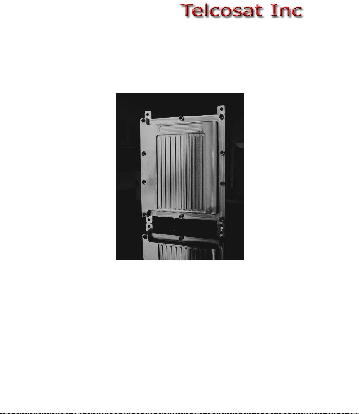
The RBB 850 Repeater is enclosed in a weather proof enclosure. System comes with instruction manual
and attached power cord.
TELCOSAT RBB850
Document use is restricted to that described on cover
9
Fig. 1-1
Typical TELCOSAT INC remote location Site System
TELCOSAT RPT 900
bidirectional
Cable Grounding Kits
Fig. 1-1 TELCOSAT INC Remote Location Site Configuration
External wall or tower mount antenna/YAGI
Cable Grounding Kits
Fill-in Antenna
Fig. 1-1
1.3 RBB 850 SPECIFICATIONS
Appendix A contains the TELCOSAT RBB 850 Repeater Specifications.
1.4 TECHNICAL ASSISTANCE
Technical assistance on the TELCOSAT RBB 850 Repeater is available through:
TELCOSAT Customer Service Center,
Phone: 1-403-291-4031.
Fax: 1-403-291-3059
EMAIL: inquiries@telcosat.com
CHAPTER 2
OPERATIONAL OVERVIEW
2.1 GENERAL
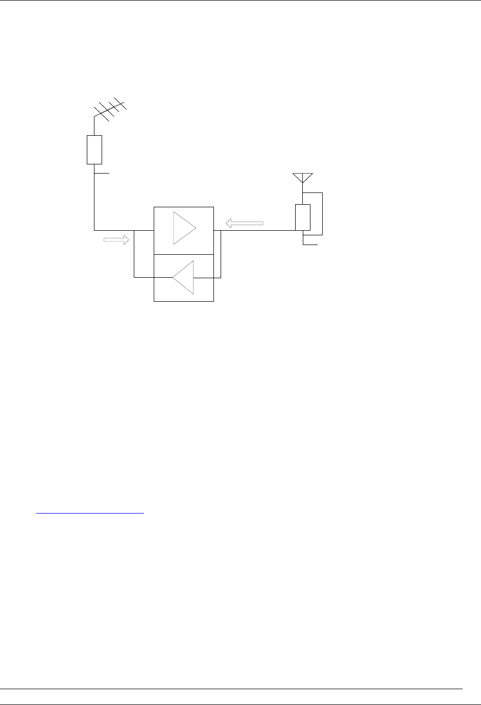
The TELCOSAT RBB 850 provides service at cellular radio frequencies 824/849MHz & 869/894MHz.
Downlink RF signals from a donor cell site are routed through a pick-up antenna, through a Diplexer
then continues to be process by the amplifier chain. The RF signal is amplified and filtered to reject out-
TELCOSAT RBB850
Document use is restricted to that described on cover
10
of-band IM products and unwanted radio signals. The downlink RF is injected into a fill-in antenna
(coverage antenna) for null-area coverage.
The Up-link signals from mobile units are received into the coverage antenna of the repeater. The
incoming signal then passes through a Diplexer, then amplified in the Up-link modules and finally the
power amplifier. The Up-link process is the same as the Down-Link process.
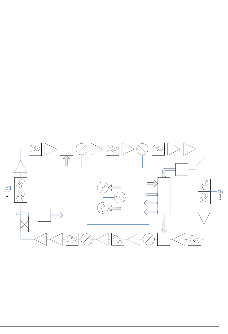
2.2 OSCILLATION DETECTION
The RBB 850 has an oscillation detection function. Upon detection of oscillation the repeater will shut
down for a short duration, approximately 25 seconds. After 25 seconds the repeater will restart, reduce
the RF gain and determine if the repeater is stable. The repeater will continue this process until the
oscillations is eliminated. If oscillation cannot be eliminated the repeater will activate the disable mode
and will cease to transmit.
The repeater requires a power cycle to reset the auto oscillation detection process, or alternatively the
repeater can be reactivated via the GUI web interface.
RBB 850 REPEATER
LNA
DL PLL+VCO
DL RF BPF IF BPFIF Amp1
IF BPF
UL RF BPF
PA
UL PLL+VCO
IF Amp 2
-
Power
Det
uC
Area
fill
ANT
DL RF BPF Driver PA
Power
Det
RF Amp1
Dig
Att
Driver
Dig
Att 1
UL RF BPF
LNA
DL LO
UL LO
Dig Att Dl
Dig Att UL
Dig Att DL
Pout UL
Pout UL
TCXO
Pout DL
UL LO
DL LO
Donor
ANT
Figure 2-1 illustrated a simplified block diagram of the RBB 850 Cellular Repeater.
2.3 AC POWER DISTRIBUTION
AC input power via a power cord which feeds a power supply that converts the AC to DC low voltage.
The DC power provides all the necessary requirements for the active components.

TELCOSAT RBB850
Document use is restricted to that described on cover
11
The repeater is equipped with a red LED power on light.
Power Supply Specifications,
-40c° to +50c° Operating Temperature Range
Short circuit, over power and over voltage protection
Input Power, 100-240 VAC
47/63 Hertz
Output Power, 12VDC/5AMPS
Approvals, UL, CUL, CE
CHAPTER 3
WARNING. This is NOT a CONSUMER device. It is designed for an installation by FCC
LICENSEES and QUALIFIED INSTALLERS. You MUST have an FCC LICENSE or express
consent of an FCC licensee to operate this device. Unauthorized use may result in significant
forfeiture penalties, including penalties of $100,000 for each continuing violation.
INSTALLATION
READ THESE INSTRUCTIONS PRIOR TO INSTALLATION
3.1 WARNING
Cellular Repeaters should be installed by fully trained technicians. Improper installation and excessive
RF power levels can cause interference with the operation of cellular towers.
Antennas must be mounted in a secure safe manner and according to safe working practices.
To protect your equipment, lightning protection hardware is recommended when installing a cellular
repeater unit.
Antennas must not be installed near overhead electrical power lines as this can cause serious injury
and or death.
If you require any additional installation guidelines then please consult your supplier or consult with
an RF Systems Engineer.

TELCOSAT RBB850
Document use is restricted to that described on cover
12
3.2 TOOLS REQUIRED
Spectrum analyzer with a tracking generator, frequency ranges 1 Gigahertz.
Optional Signal Generator for onsite testing of the repeater, frequency range of 1 Gigahertz minimum.
Antenna analyzer.
Computer with all necessary cables.
Multi-meter.
Hand tools.
Water proofing tape.
Coax cable straps for support.
Cellular Phone.
3.3 ANTENNA REQUIREMENTS
ANTENNAS: please read your manufacturers antenna specifications before installation. Your antenna
will require a type “N” connection. The antenna, coax, and fittings must be 50 ohms impedance.
MAXIMUM ANTENNA SIZE CONNECTED TO THE RBB850 REPEATER IS 18dBi,
The cellular repeater requires antennas that operate in the desired frequency range of the cellular
repeater. The RBB850 Repeater has a frequency operating range of 824 to 849 Megahertz for the up-
link, and 869 to894 Megahertz for the downlink. Your antennas must operate within these frequencies.
Failure to select the proper antennas will degrade the performance of your repeater.
NOTE:
“UP-LINK” is the radio link from your hand held cellular phone to the cellular tower in the frequency
range of 824/ 849 Megahertz
“DOWN-LINK” is the radio link from the cellular tower to your cellular phone in the frequency range of
869 /894 Megahertz.
3.4 ANTENNA ISOLATION & COAX CABLES
To protect wireless cellular networks from interference caused by oscillation, the RBB850 Repeater
has internal automatic oscillation detection/control and auto shut down of the repeater.
Improper installation practices could can initiate automatic shut-down of your repeater.
All repeaters require antenna isolation to prevent oscillation. The usable gain level of your repeater is
directly linked to the antenna isolation values. The maximum gain of your repeater must be adjusted to
a minimum of 10 dB lower than your antenna isolation values. For example, if your antenna isolation
value is 75dB then your maximum usable repeater gain is 65dB.
Due to the variations of system layouts and requirements it is not possible to have one procedure that
will suffice every installation. You are strongly advised to acquire the services of an RF system designer
to calculate your antenna isolation requirements.
TELCOSAT RBB850
Document use is restricted to that described on cover
13
Ensure that your antennas are at the maximum possible distance apart. Do not place antennas in close
proximity to each other; otherwise you will activate the oscillation detection process.
Coax cables should be low loss 50 ohm, and suitable for 800 Mhz band frequency.
Antenna connections should be clean and moisture free. Do not spray lubricant into the connectors as
this prevents the signal traveling through the coax. Use a cleaning solvent that has no oil and does not
leave any residue. High quality oil-less contact cleaner is suitable.
All coax connectors must be water tight and wrapped with water proof tape. Any moisture in the
connectors will degrade or eliminate the signals.
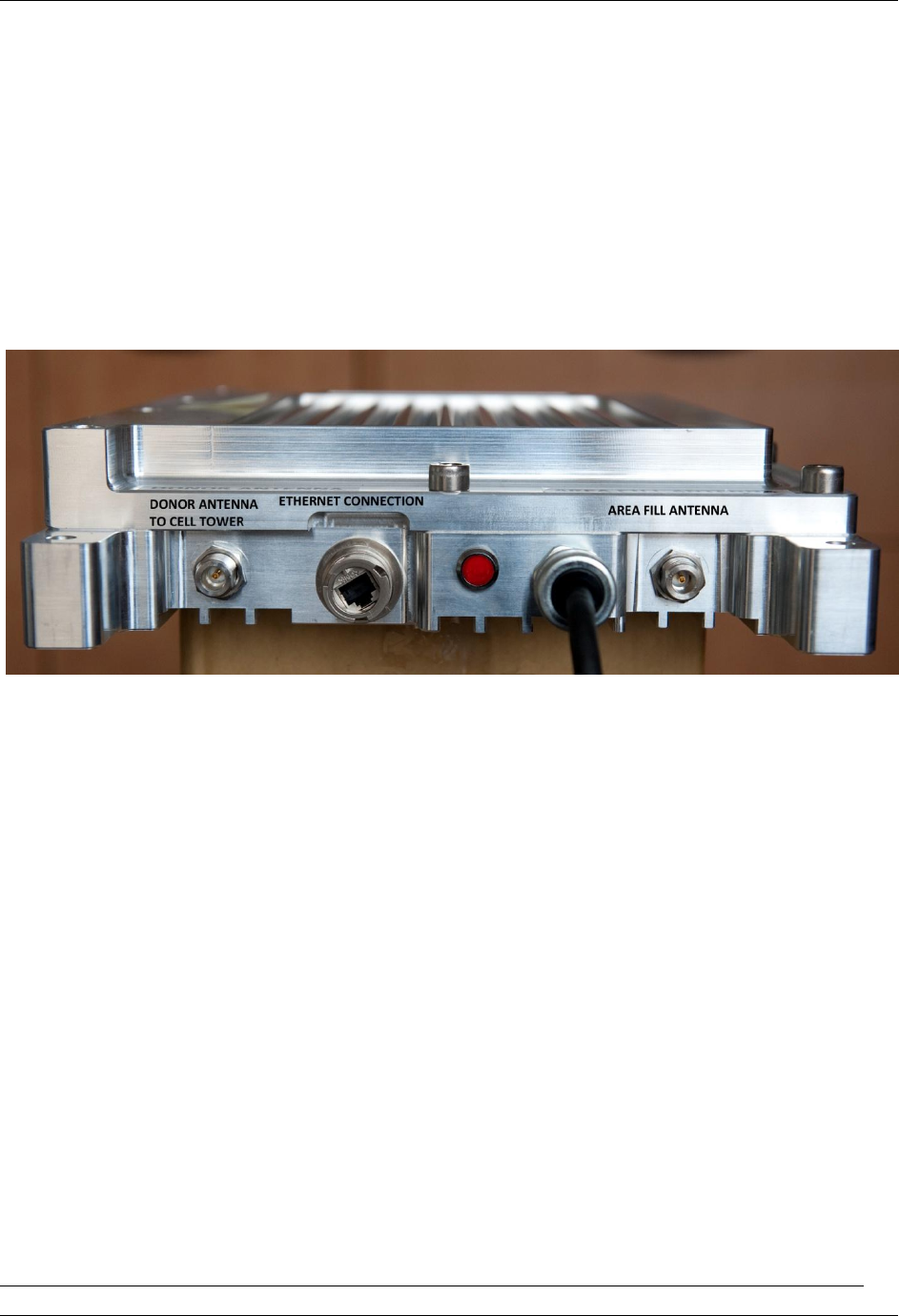
3.5 ANTENNA CONNECTIONS ON THE RBB850
The RBB850 can be installed indoors or outdoors. If mounted indoors ensure there is no elevated room
temperatures and free flowing air for cooling of the repeater.
Connect the antenna that is aimed at the Cell Tower to the bottom left side N connector.
Connect the antenna that is aimed towards the Area Fill (target site) to the bottom right side N
connector.
Connect your Ethernet cable to the connector socket located on the left side of the power on LED light.
NOTE; Water proof boot cover for the Ethernet connection, contact your Repeater supplier.
3.6 Aligning the Donor Antenna.
With the aid of a spectrum analyzer, connect your Donor antenna (antenna aimed at the Cell tower) to
your spectrum analyzer and adjust your antenna to the maximum receive signal level. This process
assures the Donor antenna is accurately aligned to the cell tower.
3.7 Adjusting area fill coverage (down link) to the target site/location.

TELCOSAT RBB850
Document use is restricted to that described on cover
14
Accessing your RBB850 software interface, Increase your downlink receive signal in 2dB increments to
the required receive level. You will see the receive signal bars on your cellular phone increase in
strength. Use test and measuring equipment to accurately adjust the down link receive signal level.
3.8 Adjusting Uplink (Reverse Link) RF power to cellular tower.
You are strongly advised to consult an RF Engineer to calculate the reverse link RF power settings.
Too much RF signal transmitting to the cellular tower can cause interference and degrade the
performance of the cellular tower causing service disruptions. This must be avoided 100%
Accessing your RBB 850 software interface you can adjust your RF reverse link power settings.
For basic settings start your reverse link RF power levels at the lowest setting. Increase your RF transmit
level in 1 dB increments. After every adjustments try to make a call. If your call does not connect
increase the power setting 1dB and try to make a call. Continue this process until a call is established.
When you can connect to the cell tower the call should quickly connect and the calling process will
immediately start and you will hear the dialing tone. At this point increase your power level an
additional 2dB. Make a test call for connectivity quality.
This is your minimum RF power transmit setting for the reverse link to the cell tower.
Consult with the Wireless operator while you adjust your reverse link RF power settings. The operator
can monitor the receive signals from your RBB 850 at the cell tower. They will instruct you if you can
increase power or you need to decrease your power settings.
If you follow this process and you cannot make a call you must turn the RBB850 off and disconnect your
power cord. Consult with your RF Technician/Engineer to rectify the problem.
3.9 ADJUSTING REVERSE LINK MAXIMUM POWER LEVEL.
Additional protection is gained if the reverse link maximum power level is adjusted to prevent the
possibility of sudden unwanted high input RF levels. This can happen in various ways, mobile cellular
vehicle boosters coming within range of the cellular repeaters, malfunctioning cellular phones, or other
stray signals.
The RBB850 has an adjustable Maximum allowable RF Power limit. The maximum allowable RF power
limit is 25dBm. The digitally controlled attenuator will not permit RF signal levels greater than 25dBm.
The user can decrease the maximum allowable RF transmit power from 25dBm to 0.0dBm. The
microprocessor controlled digital attenuator will maintain the preset allowable RF transmit power limit
regardless of unwanted high input signal levels.
Decreasing the level of maximum RF reverse link power helps to reduce possible cellular tower
interference for sudden elevated RF power, especially when the RBB850 repeater is installed in areas
where the cellular towers are less than 5 kilometres (2 miles) distance.
TELCOSAT RBB850
Document use is restricted to that described on cover
15
CHAPTER 4
CONNECTING THE RBB850 REPEATER TO A COMPUTER OR NETWORK
4.1 The default IP address of the Repeater
IP 192.168.1.100
NETWORK MASK
255.255.255.0
To connect your computer to the repeater you need to configure your network card in your computer to
the following IP
IP 192.168.1.99
NETWORK MASK
255.255.255.0
Start your Internet Browser, for example Windows Internet Explorer.
In the browser address bar type in, http://192.168.1.100
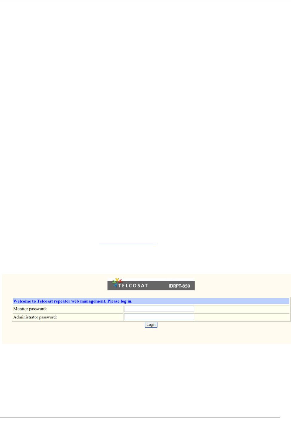
REPEATER LOGIN SCREEN
4.2 The Repeater log in page should appear. See image below.
REPEATER LOGIN PAGE
The default log in password for the Administration is “telcosat“
The default log in password for the Monitoring password is “telcosat“
You can change the password in the System Setup Screen.
The repeater will allow two levels of password.
The Monitor Password only allows the user to view the details and cannot make any adjustments.
TELCOSAT RBB850
Document use is restricted to that described on cover
16
The Administrator Password allows the user to make all adjustments to the repeater and also change
password settings.
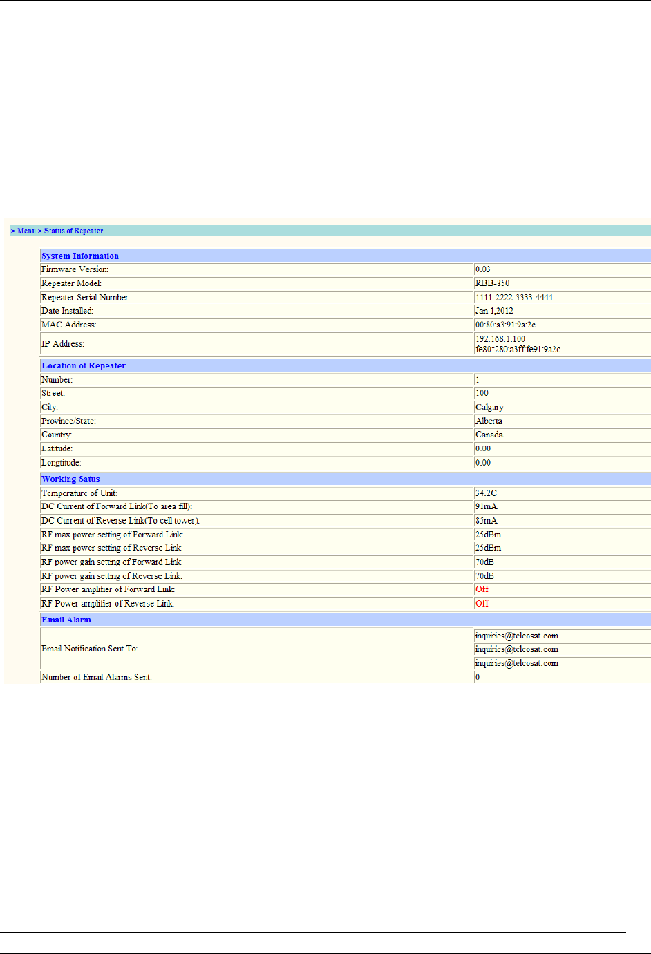
REPEATER STATUS PAGE
4. 3
The “Status Page” is a summary of current settings of the repeater. This page is only a status
page. No repeater adjustments can be performed from this screen.
When the repeater is remotely accessed using the Monitoring Mode, this page is displayed.
TELCOSAT RBB850
Document use is restricted to that described on cover
17
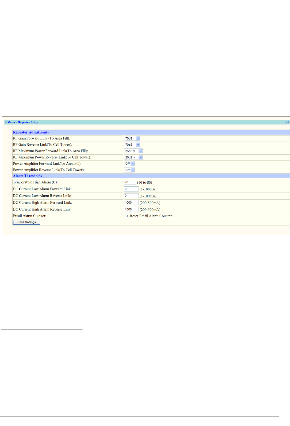
REPEATER SET UP PAGE
4.4
The Repeater Set-up Page is where all adjustments/settings are performed. Enter the required setting in
the box and then click the “Save Settings” box. You can verify the setting by reviewing the “Status Page”
4.5 ALARM THRESHOLDS
Alarm thresholds will send an email alerting that the number in the threshold boxes have be reached.
For example, the Temperature high alarm box is set to 70c°. If the temperature of the repeater reaches
70c° an email alert will be sent from the repeater.
Setting the Alarm Thresholds
Power up the repeater, allow the unit to warm up to operating temperature, log in and go to the
Repeater “Status Screen”. Look for the Repeater Status Screen, then look for Working Status Box on
the same page.
DC current of the Forward Link and the DC current of the Reverse Link.
4.6 High Current Alarm Settings

TELCOSAT RBB850
Document use is restricted to that described on cover
18
Using the data from the manual for this example only, REPEATER STATUS PAGE,
Displayed is DC current Forward Link 91mA
Displayed is DC current Reverse Link 85mA.
This is the normal operating current from your repeater and should be used as a guide line for Alarm
Threshold.
Add another 5mA to each value, 91+5= 96mA Forward Link
85+5=90mA Reverse Link
The new values can be inserted into the Threshold Alarm settings
DC current High alarm Forward Link set to 96mA
DC current High alarm Reverse Link set to 90mA
In the event that the current reaches this alarm setting, an email will be sent, sudden high current could
indicate a possible problem.
4.7 Low Current Alarm Settings
Using the same data set from the Status Page.
For low current alarm threshold we need to be less than the normal operating current. For low current
settings minus 5mA from the operating current.
Minus 5mA to each value, 91-5= 86mA Forward Link
85-5=80mA Reverse Link
DC current low alarm Forward Link set to 86mA
DC current low alarm Reverse Link set to 80mA
In the event that the current reaches this alarm setting, an email will be sent.
Sudden low current could indicate a possible problem or failure.
4.8 EMAIL ALARM COUNTER.
The email alarm counter records the number of times and email was sent. You can reset the counter to
zero by clicking the Reset Alarm Counter Box.
TELCOSAT RBB850
Document use is restricted to that described on cover
19
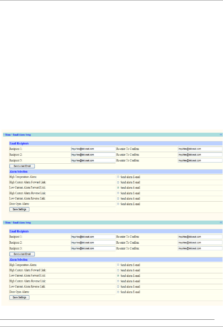
ALARM SET-UP PAGE
4.9
This page allows the user to configure the email settings for the alarm recipient.
This page allows the user to enable or disable the Send Alarm Email.
After entering the information the user must click the Saves Settings box.
TELCOSAT RBB850
Document use is restricted to that described on cover
20
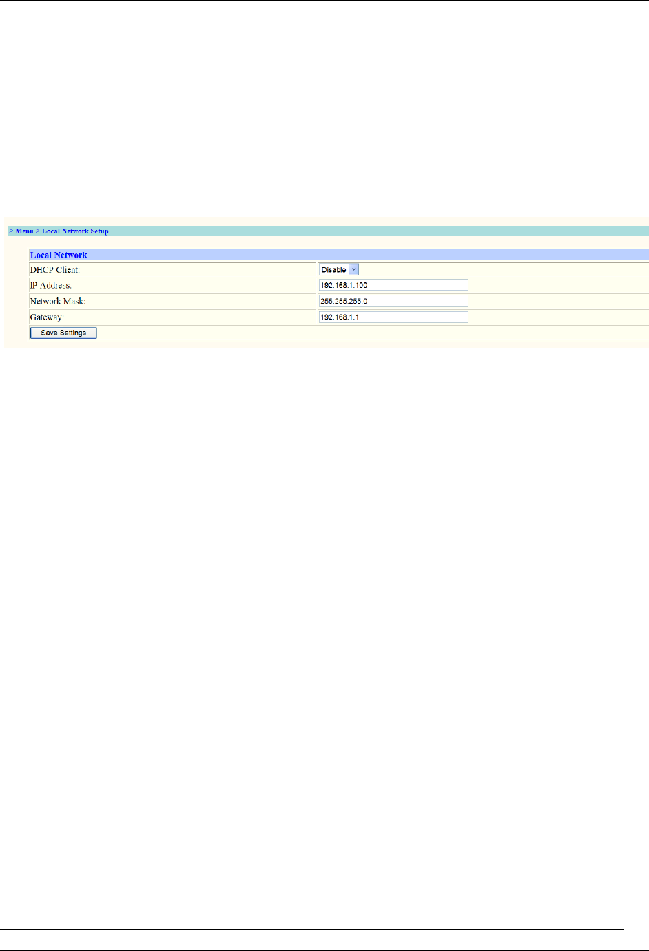
LOCAL NETWORK SETUP
4.10
The local network set-up screen allows the user to modify the network setup.
Enter the new information into each box and click the Save Settings box.
Verify the settings in the System Status page.
The user must record the network settings for future reference and access requirements.
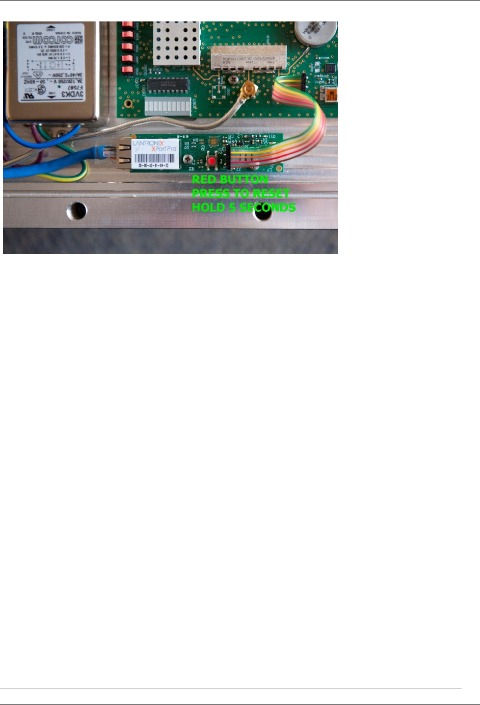
4.11 RESETTING THE IP/NETWORK MASK DEFAULT
In the even the IP/Network information is not available then a manual reset has to be performed on the
repeater.
Remove the 10 Allen Head type bolts, use an 8 mm Hex Key wrench.
There is a small push button, press and hold for 5 seconds.
The default IP will be reset to 192.168.1.100
The default Network Mask will be reset to 255.255.255.0
See attached image to locate the RESET BUTTON.
TELCOSAT RBB850
Document use is restricted to that described on cover
21
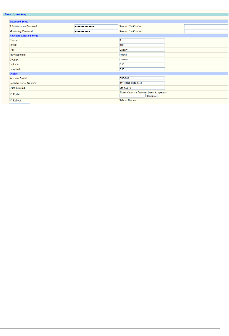
4.12 PASSWORD SETUP AND REPEATER LOCATION SCREEN
Administration Password
Type in your new password in the Administration box. You will be required to retype your password to
ensure accuracy. It is recommended that you use minimum of 12 characters, letter number mix for
security. Click the Save Settings button.
The Administration screen allows the user to access all settings and make changes.
Your Administration password should be different from your Monitoring Password.
Monitoring Password
Type in your new password in the Monitoring box. Retype your password to ensure accuracy. Click the
Save Settings button.
The Monitoring screen does not allow the user to make any changes. The user can only view the data.
System Setup Screen
4.13 Repeater Location Setup Screen.
The repeater location box allows the user to insert the address and or location of the repeater. The
location Latitude and Longitude are in Degrees Decimal. After entering data Click the Save Settings box.
TELCOSAT RBB850
Document use is restricted to that described on cover
22
CHAPTER 5
WARRANTY AND REPAIR
5.1 WARRANTY
Your Telcosat Repeater is guaranteed against manufacturers defects for 2 years.
Telcosat Inc retains the right to decide if the fault/defect is a manufacturer’s defect.
Telcosat Inc will not accept liability for any damage caused through improper use or poor installation
practices.
5.2 Limited Warranty
Hardware. Telcosat Inc or any subsidiary selling the Product (RBB850 Cellular Repeater) warrants that
commencing from the date of shipment for a period of 2 years factory warranty against manufactures
defect. Warranty includes parts and labour only.
Note, freight is not included in the warranty. Shipper is liable for all freight costs.
Telcosat Inc reserves the right to determine if repair claims are Warranty, or damage caused by some
other reason, for example and not limiting to, lightning strikes etc,.
EXCEPT AS SPECIFIED IN THIS WARRANTY, ALL EXPRESS OR IMPLIED CONDITIONS,
REPRESENTATIONS, AND WARRANTIES INCLUDING, WITHOUT LIMITATION, ANY IMPLIED WARRANTY
OR CONDITION OF MERCHANTABILITY, FITNESS FOR A PARTICULAR PURPOSE, NON-INFRINGEMENT,
SATISFACTORY QUALITY, NON-INTERFERENCE, ACCURACY OF INFORMATIONAL CONTENT, OR
ARISING FROM A COURSE OF DEALING, LAW, USAGE, OR TRADE PRACTICE, ARE HEREBY EXCLUDED
TO THE EXTENT ALLOWED BY APPLICABLE LAW AND ARE EXPRESSLY DISCLAIMED BY TELCOSAT INC,
ITS SUPPLIERS AND LICENSORS. TO THE EXTENT AN IMPLIED WARRANTY CANNOT BE EXCLUDED,
SUCH WARRANTY IS LIMITED IN DURATION TO THE EXPRESS WARRANTY PERIOD. SOME STATES OR
JURISDICTIONS DO NOT ALLOW LIMITATIONS ON HOW LONG AN IMPLIED WARRANTY LASTS; THE

TELCOSAT RBB850
Document use is restricted to that described on cover
23
ABOVE LIMITATION MAY NOT APPLY. THIS WARRANTY GIVES CUSTOMER SPECIFIC LEGAL RIGHTS,
AND CUSTOMER MAY ALSO HAVE OTHER RIGHTS WHICH VARY FROM JURISDICTION TO
JURISDICTION. This disclaimer and exclusion shall apply even if the express warranty set forth above
fails of its essential purpose.
Restrictions. This warranty does not apply if the Product or any other equipment upon which the
Product is authorized to be used (a) has been altered, except by Telcosat Inc, (b) has not been installed,
operated, repaired, or maintained in accordance with instructions supplied by Telcosat Inc, (c) has been
subjected to abnormal physical or electrical stress, misuse, negligence, accidents forces of nature,
earthquakes, lightning strikes, vandalism, and civil unrest.
5.3 Storage of Equipment
When storing your equipment you must place the unit in a dry location, away from direct sun exposure
and take measures to prevent moisture/condensation build up in your repeater enclosure.
Silica Gel bags should be placed inside the enclosure to absorb moisture. The door on the enclosure
should be closed and sealed. The silica gel bags should be changed /inspected at regular intervals to
ensure proper functionality of the material.
You are strongly advised to seek the advice of a professional company that has expertise in long term
preservation techniques of electronic equipment.
Maximum storage temperatures of your Telcosat Repeater is +50c (122F)
Minimum storage temperature of your Telcosat Repeater is -40c (-40F)
TELCOSAT RBB850
Document use is restricted to that described on cover
24
Appendix A
Specifications for Telcosat Repeater Model RBB850
Frequency Range:
Down link 824-849MHz / Up-link 869-894MHz
Overall systems Gain
70dB
Band Width
25 Megahertz
RF Composite Power
+25dBm
Noise Level
< Less than 5dB
RF Gain Adjustment
31.5 dB with 0.5dB increments via software
Antenna Connector
N type Female 50 ohms
EVM
<less than 3%
Ethernet Connector
RJ45
Power Requirements
110/240 VAC 47/63 Hertz
Power Consumptions
20 Watts
Enclosure Rating
IP67
Enclosure Material
Aluminium
TELCOSAT RBB850
Document use is restricted to that described on cover
25
EMC
EMC Compliant
Operating Temperature
-40°c to +50°c
Storage Temperature
-40°c to +70°c
Weight
25 lbs (11.4 Kilograms)
Dimensions
H x W x D 16.5”ins x 12”ins x 3inches
(470mm x 305mm x 76mm)
Warranty
Two years
FCC and Industry Canada
Certified FCC and Industry Canada
Appendix A
NOTE RULE: RSS-133 section 5.3
The manufacturers rated output power of this equipment is for single carrier operation. For situations when
multiple carrier signals are present, the rating would have to be reduced by 3.5dB, especially where the out-put
signal is re-radiated and can cause interference to adjacent band users. This power reduction is to be by means of
input power or gain reduction and not by an attenuator at the out-put device
FCC/IC RF Exposure Requirements.
Maximum Antenna size 18dBi
FCC antenna(s) used for this transmitter must be installed to provide a separation distance of at least 51.61
centimetres (cm) (20.32 inches) from all persons, and must not be co-located or operating in conjunction with
any other antenna or transmitter.
Any modifications to this device will void FCC and IC approvals
APPENDIX B
RETURNED GOODS PROCEDURE

TELCOSAT RBB850
Document use is restricted to that described on cover
26
B1. Technical Information
Contact Telcosat Inc or your supplier to determine whether or not an item should be returned for repair.
Contact Telcosat Inc 403 291 4031
Email, inquiries@telcosat.com
B2. Return Identification
Please provide the following information with each repair.
Date of requested repairs.
Customer name with full address for returning goods
Contact person responsible for returning the product for repairs
Client telephone number
Serial number
Original purchase date
Reason for return.
B3. Shipping Procedure
Ship all returned goods PREPAID to the following address:
Product Repairs,
Telcosat Inc,
Bay 116 1919 – 27th Avenue NE,
Calgary, Alberta,
Canada. T2E 7E4
Telephone 403 291 4031
Fax 403 291 3059
Email:inquiries@telcosat.com
Your commercial invoice must state REPAIR/RETURN. Failure to provide proper Commercial Invoices
may result in taxes and duties which will be charged back to the client.
B4. Return Shipments
All returned shipments will be sent PREPAID, to the customer’s indicated address.
Any extra packaging material will be charged back to the client.
B5. Repair / Return Status
Under normal circumstances defective items will be replaced repaired within 5 working business days of
receipt.
Telcosat Inc will inspect and test your repeater in a lab environment. Upon completion of the inspection
a written estimate will be provided to the client. A minimum charge of $500.00 will be charged to the
client to cover the cost of inspection and testing plus minor repairs.