User Manual
Manual Number: TELCOSAT RPT 1900
Document use is restricted to that described on cover
OPERATION & MAINTENANCE MANUAL
CELLULAR REPEATER MODEL RPT 1900

Document use is restricted to that described on the cover
2
TELCOSAT INC
OPERATIONS & MAINTENANCE MANUAL
CELLULAR REPEATER MODEL RPT 1900
TELCOSAT RPT 1900
The information set forth in this document and all rights in and to inventions disclosed
herein, and patents which might be granted thereon disclosing, employing or covering the
materials, methods, techniques or apparatus described herein are the exclusive property
of Telcosat Inc.
This document is an operation and maintenance manual. No disclosure or reproduction of
the information or drawings shall be made of any other purpose without the prior written
consent of Telcosat Inc. Use of the information contained herein to fabricate or assemble
any item in whole or in part is expressly prohibited.
A Canadian Company
116, 1919 – 27th Ave NE,
Calgary, Alberta, Canada. T2E 7E4
Tel Canada (403) 291-4031
Fax Canada (403) 291-3059

TELCOSAT RPT 1900
Document use is restricted to that described on cover 4
SAFETY SUMMARY
High voltage is used in the operation of
this equipment. Death on contact may
result if personnel fail to observe the
following safety precautions:
Only qualified trained personnel can install this equipment. Electrical connection and installation
must meet your local Electrical Safety Installation codes.
Prior to any maintenance or inspection of this device disconnect the power supply.
Do not remove covers or access plates on the equipment unless you are a trained technician and
authorized to carry adjustment and maintenance for this apparatus.
When installing antennas always be aware of high voltage overhead power lines. Contact with
power lines will result in severe injury and or death.
To prevent electrical shock or damage to the equipment, do not operate the repeater until you
thoroughly understand the operation and function of all controls, indicators, and connectors.
The RPT1900 Repeater weighs approximately 55 lbs/ 25kilograms. The repeater must be attached
to the appropriate supporting device using the welded supporting lugs on the enclosure. The nuts
and bolts must be a minimum Grade 5, ¼” (6mm) diameter and corrosion resistant.
FIRST AID
In case of electrical shock:
THIS PERSON COULD STILL BE INCONTACT WITH ELECTRICAL POWER. DO NOT
TOUCH THIS PERSON BEFORE YOU INSULATE YOUR SELF FROM THE ELECTRICAL
SOURCE.
Turn off the electrical power.
If you cannot turn off the electrical power, pull, push, or lift the person to safety using a dry
wooden pole, a dry rope, or some other insulating material. Do not use any metallic objects to
move this person.
After the injured person is no longer in contact with the electrical source, obtain/perform
immediate medical attention.

TELCOSAT RPT 900 Rev. 01 REGULATORY NOTICE
Document use is restricted to that described on cover II
NOTE RULE: RSS-131 section 5.3
The manufacturers rated output power of this equipment is for single carrier
operation. For situations when multiple carrier signals are present, the rating
would have to be reduced by 3.5dB, especially where the out-put signal is re-
radiated and can cause interference to adjacent band users. This power
reduction is to be by means of input power or gain reduction and not by an
attenuator at the out-put device
FCC/IC RF Exposure Requirements
The antenna(s) used for this transmitter must be installed to provide a separation
distance of at least 88.09cm from all persons, and must not be co-located or
operating in conjunction with any other antenna or transmitter. This minimum
safe distance is based on maximum antenna gain of 18 dBi.
Regulatory Notice: Any modifications to this device will
void FCC and IC approvals.

TELCOSAT RPT 1900 TABLE OF CONTENTS
Document use is restricted to that described on cover 5
TABLE OF CONTENTS
CHAPTER 1
1.1 GENERAL 1-1
1.2 INTRODUCTION 1-1
1.2.1. HARDWARE DETAILS 1-1
1.3 RPT 1900 SPECIFICATIONS 1-5
1.4 TECHNICAL ASSISTANCE 1-5
CHAPTER 2 OPERATIONAL OVERVIEW 2-1
2.1 GENERAL 2-1
2.2 DETAILED TECHNICAL RF SIGNAL PROCESSES 2-1
2.3 AC POWER DISTRIBUTION 2-2
CHAPTER 3 INSTALLATION 3-1
3.1 WARNING 3-1
3.2 TOOLS REQUIRED 3-1
3.3 ANTENNA REQUIREMENTS 3-1
3.4 ANTENNA ISOLATION & COAX CABLES 3-1
3.5. INSTALLING YOUR REPEATER 3-1
3.6 MANUAL RF GAIN ADJUSTMENTS
3.7 RSSI INDICATOR AND SIGNAL LEVELS 3-2
3.8 ALIGNING YOUR ANTENNA 3-2
3.9 ADJUSTING UPLINK POWER 3-2
CHAPTER 4 WARRANTY REPAIR
4.1 WARRANTY
4.2 LIMITED WARRANTY
CHAPTER 5 EQUIPMENT LONG TERM STORAGE
APPENDIX B RETURN GOODS PROCEDURE B-1
B2. Returned Goods Procedure
B3. Shipping Procedure
B4. Returned Shipments
B5. Repair / Return Status

TELCOSAT RPT 1900
Document use is restricted to that described on cover 1-2
CHAPTER 1
SCOPE
1.1 GENERAL
The TELCOSAT RPT 1900 Cellular Repeater (consisting of UPLINK and DOWNLINK
bidirectional system) contains operational and maintenance information. This manual consists of
four chapters and two appendices as follows:
Chapter 1 outlines the manual contents, with description and general application notes
Chapter 2 contains an operational overview and tune-up procedures (single and multi
carrier).
Chapter 3 contains installation procedures, packing and shipping instructions.
Chapter 4 contains the repeater warranty information
Appendix A contains unit specifications and environmental data.
Appendix B contains the return goods procedure.
1.2 INTRODUCTION
The TELCOSAT RPT 1900 is an off air bidirectional wireless cellular band amplifier also known
as a “Repeater”.
The RPT1900 cannot demodulate or modulate the signals that pass through the RPT 1900.
The RPT1900 Cellular Repeater will allow cellular coverage to be applied in areas where
conventional cellular wireless signals do not reach. These areas may be in tunnels, parking
structures, buildings, underground, and signal shadow areas. The Repeater can also be deployed
to extend cellular service or direct cellular service to low density populated areas and other places
where the natural surface terrain creates shadow areas, for example valleys, hills etc,.
Throughout this manual, the terms DOWNLINK and UPLINK are used. Downlink is the
direction of RF energy from the Base Station to the end users mobile cellular handsets. The
Uplink is the RF signal path direction from the Mobile Cellular handsets to the Base Station
(cellular Tower).
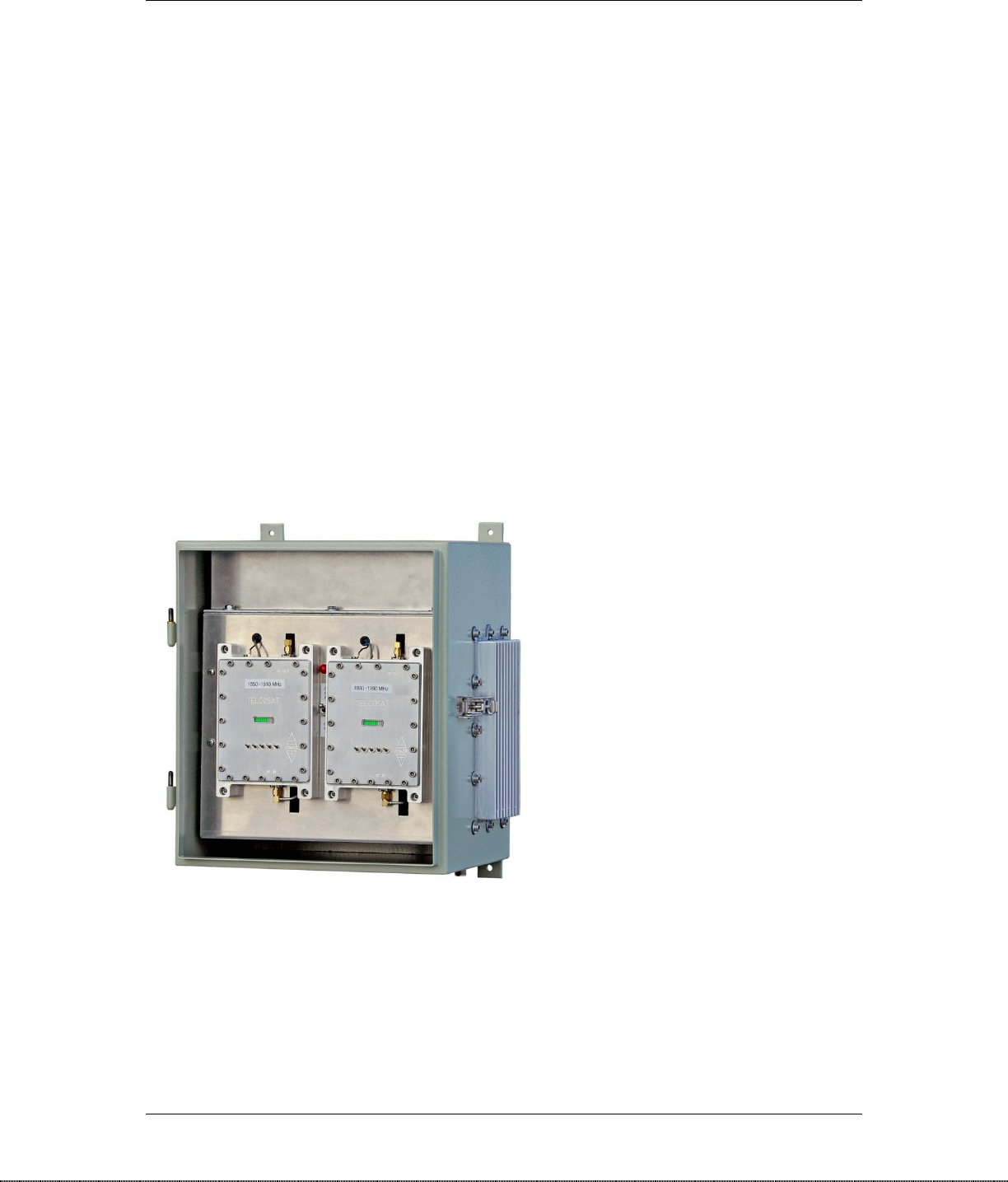
1.2.1 Hardware Details
The RPT1900 enclosure contains all the required amplifiers and miscellaneous electronic
circuitry. No other electronic devices are required. The materials supplied with the Repeater are
the “operators” user manual.
There are no internal adjustments on the electronic circuit boards by the operator/end user.
TELCOSAT RPT 1900
Document use is restricted to that described on cover 1-2
The installation of the Repeater will require the connection of external antennas, coax cables,
antenna mounting hardware etc. All installation work should only be completed by qualified
technical personnel.
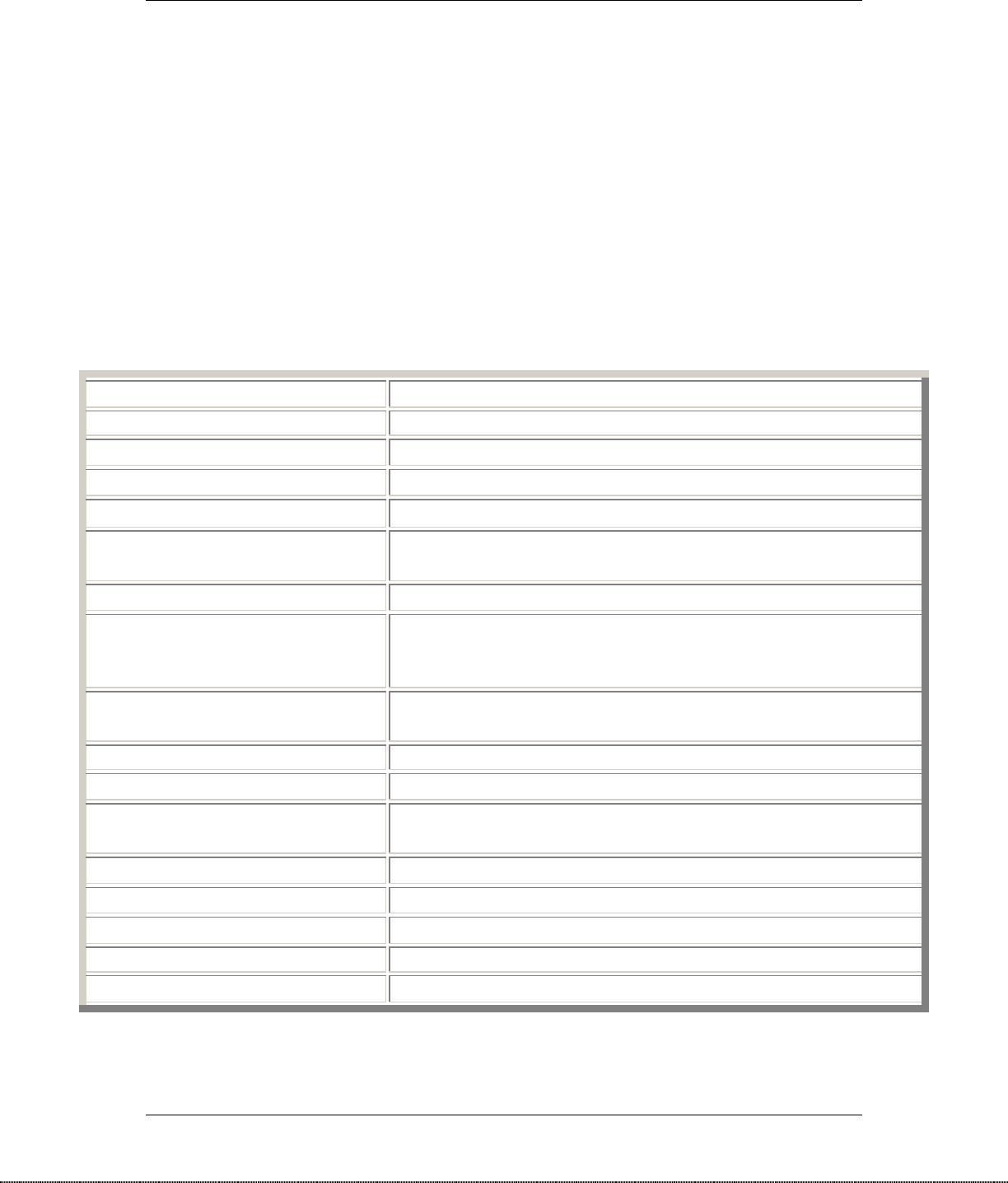
1.3 RPT 1900 SPECIFICATIONS
Specifications for the Telcosat Repeater Model RPT 1900
Frequency Range:
Down link 1930-1990MHz / Up-link 1850-1910MHz
Overall systems Gain
90dB Uplink and 90dB downlink
Pass band ripple:
+/- 2.5dB max. within 3dB Pass Band
Channel ripple:
.2dB max.
Absolute Delay:
Less then 2 µsec.
Rx Noise figure @ maximum Gain:
4dB Maximum
IMD 2 tone :
43 dBc at maximum power
Power Output
+30 dBm RMS Uplink and +30dBm RMS down-link
+32.8 dBm Peak Power Uplink / +32dBm Peak Power down-link
Antenna Impedance Rx and TX :
Z= 50 Ohms
Max SWR in/out:
1.5 to 1 max
Manual Gain Control
50dB total in 2db steps
Power Supply:
28VDC/55Watts or 90 to 260 AC / 55 Watts consumption
Operating Temperature
-30°C to +50°C
RF Connectors:
N- Type Female
Mechanical Specifications:
Size: 14.5" x 16.5" x 11.5" 36 x 41 x 29 cm
Weight:
55 pounds/ 25Kg typical
Enclosure type:
NEMA 4A, 12
Table 1

TELCOSAT RPT 1900
Document use is restricted to that described on cover 1-2
1.4 TECHNICAL ASSISTANCE
Technical assistance on the TELCOSAT RPT 1900 Repeater is available through:
TELCOSAT Customer Service Center
Phone: Canada : 403-291-4031
Canada : Fax: 403-291-3059
Email : inquiries@telcosat.com
CHAPTER 2
OPERATIONAL OVERVIEW
2.1 GENERAL
The TELCOSAT RPT 1900 provides service at cellular radio frequencies in the range of 1850
MHz to 1910 MHZ uplink (reverse link), and 1930 MHz to 1990 MHz downlink (forward link).
The RPT 1900 is an “off air repeater” and cannot demodulate signals, cannot modulate signals
and cannot change signal frequency.
Downlink (forward link) RF signals from a donor cell site are routed through a pick-up antenna,
through a Diplexer then continues to be process by the amplifier chain. The RF signal is
amplified for path and cable losses and filtered to reject out-of-band IM products and unwanted
radio signals. The downlink RF is injected into an area fill antenna (coverage antenna) for area
coverage.
The Up-link (reverse link) signals from mobile cellular hand- sets are received into the coverage
antenna of the repeater. The incoming signal then passes through a Diplexer, then amplified in the
Up-link modules and finally the power amplifier. The Up-link process is the same as the Down-
Link process.
See section 2.3 illustrated a simplified block diagram of the RPT 1900 Cellular Repeater.
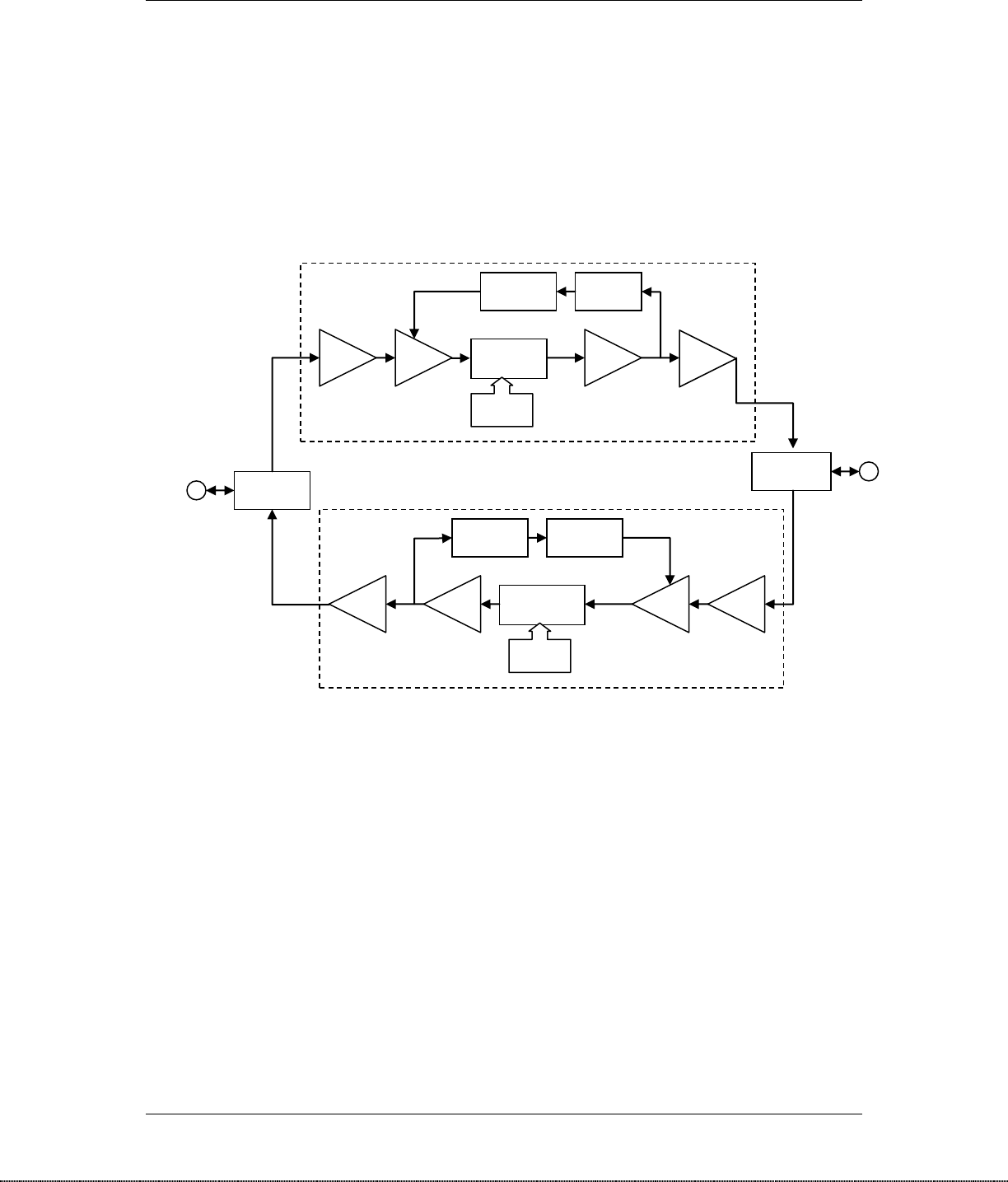
2.2 Detailed Technical RF Signal Processes
Description of Operation
AUTO GAIN CONTROL / POWER CONTROL
The bi-directional amplifier (BDA) has an auto AGC/Power control function on both
signal paths that serve to protect and prevent the saturation of the power amplifier. The
amplifier has a directional coupler and power detector at the Input of the high power
amplifier to monitor the output power.
TELCOSAT RPT 1900
Document use is restricted to that described on cover 1-2
When a high signal is received the automatic level control detects the amplitude
and sends a feedback signal to a voltage variable gain amplifier which attenuates the
signal level so that output power of the amplifier does not exceed the preset limit.
Block Diagram with AGC
Duplexer
Dig Att
Duplexer
PD
MG
C
Dig Att
MG
C
AGC
PD
AGC
DownLink
1930-1990MHz
UpLink
1850-1910MHz
PA
PA
LNA
VGA
LNA
VGA
To Area
Fill
Antenna
To Donor
Antenna

TELCOSAT RPT 1900
Document use is restricted to that described on cover 1-2
.
2.3 AC POWER DISTRIBUTION
AC input power is through a power cord then a 2-pole on/off circuit breaker switch which feeds
two DIN rail mounted fuse holders with cartridge fuses rated at 2 AMPS. The fuses are
replaceable and each DIN rail fuse holder holds a spare fuse. AC power from the DIN rail fuse
holders feed two DIN rail switching power supply units. The power supply units are adjustable to
operate on either 120 VAC or 230VAC. (Customer to notify Telcosat Inc with AC power
requirement prior to shipping)
The internal power supply units convert AC line voltage to DC power, one power supply unit
supplies 10volts DC and the other power supply unit provides 28Volts DC. The DC power
provides all the necessary requirements for the active components.
CHAPTER 3
INSTALLATION
READ THESE INSTRUCTIONS PRIOR TO INSTALLATION
WARNING
DO NOT POWER UP THE REPEATER WITH OUT THE
ANTENNAS CONNECTED
3.1 WARNING
Cellular Repeaters should be installed by fully trained technicians. Improper
installation and excessive RF power levels can cause interference with the operation
of cellular towers.
Antennas must be mounted in a secure safe manner and according to safe working
practices. Lightning protection should be installed on every cellular repeater unit.
Antennas must not be installed near overhead electrical power lines as this can
cause serious injury and or death.
If you require any additional installation guidelines then please consult your
supplier or consult with an RF Systems Engineer.
3.2 TOOLS REQUIRED

TELCOSAT RPT 1900
Document use is restricted to that described on cover 1-2
RF Spectrum analyzer with a tracking generator, frequency ranges 3 Gigahertz.
Optional Signal Generator for onsite testing of the repeater, frequency range of 4 Gigahertz.
Hand held cable fault locator (TDR)
Multi-meter
Hand tools.
Water proofing tape.
Coax cable straps for support.
Cellular Phone.
3.3 ANTENNA REQUIREMENTS
ANTENNAS: please read your manufacturers antenna specifications before
installation. Your antennas will require a type “N” Female connection. The antenna,
coax, and fittings must be 50 Ohms impedance.
The cellular repeater requires antennas that operate in the desired frequency range of the cellular
repeater. The RPT1900 Repeater has a frequency operating range of 1850 Megahertz to 1910
Megahertz for the up-link, and 1930Megahertz to 1990 Megahertz for the downlink. Your
antennas must operate within these frequencies.
Failure to select the proper antennas will greatly degrade the performance of your repeater.
NOTE:
“UP-LINK” also known as “Reverse Link” is the radio link from your hand held cellular phone to
the cellular tower in the frequency range of 1850MHz to 1910 MHz
“DOWN-LINK” also known as “Forward Link” is the radio link from the cellular tower to your
cellular phone in the frequency range of 1930MHz to 1990 MHz.
The repeater requires two antennas to be connected to the system. See image Figure 4, showing
coax connectors on the bottom of the repeater enclosure.
The Donor antenna is the antenna pointing to the Cellular Tower and the Area Fill antenna is the
antenna that provides the fill signal to your desired area.
3.4 ANTENNA ISOLATION & COAX CABLES
All repeaters require antenna isolation to prevent oscillation. The usable gain level of your
repeater is directly linked to the antenna isolation values. The maximum gain of your repeater
must be adjusted to 10 to15dBm lower than your antenna isolation values. For example, if your
antenna isolation value is 75dBm then your maximum usable repeater gain is 60dBm.
Due to the variations of system layouts and requirements it is not possible to have one procedure
that will suffice every installation. You are strongly advised to acquire the services of an RF
system designer / RF radio technician to calculate your antenna isolation requirements.
TELCOSAT RPT 1900
Document use is restricted to that described on cover 1-2
Ensure that your antennas are at the maximum possible distance apart. Do not place antennas in
close proximity to each other.
Coax cables should be sized according to your system design criteria.
Antenna connections should be clean and moisture free. Do not spray lubricant into the
connectors as this prevents the signal traveling through the coax. Use a cleaning solvent that has
no oil and does not leave any residue. High quality oil-less contact cleaner is suitable.
All coax connectors must be water tight and wrapped with water proof tape. Any moisture in the
connectors will degrade or eliminate the signals.
PREPARING YOUR CELLULAR REPEATER
3.5 INSTALLING YOUR REPEATER
The Telcosat Repeater weighs in excess of 55 pounds (25 Kilograms)
Make sure that your repeater is securely bolted to a suitable support. There are four welded steel
tabs on each corner that must be used to bolt your unit onto a suitable support system. You must
use ¼” diameter grade five steel corrosion resistant bolts with lock washers and securing nuts, a
total of 4 bolts and nuts/lock washers are required
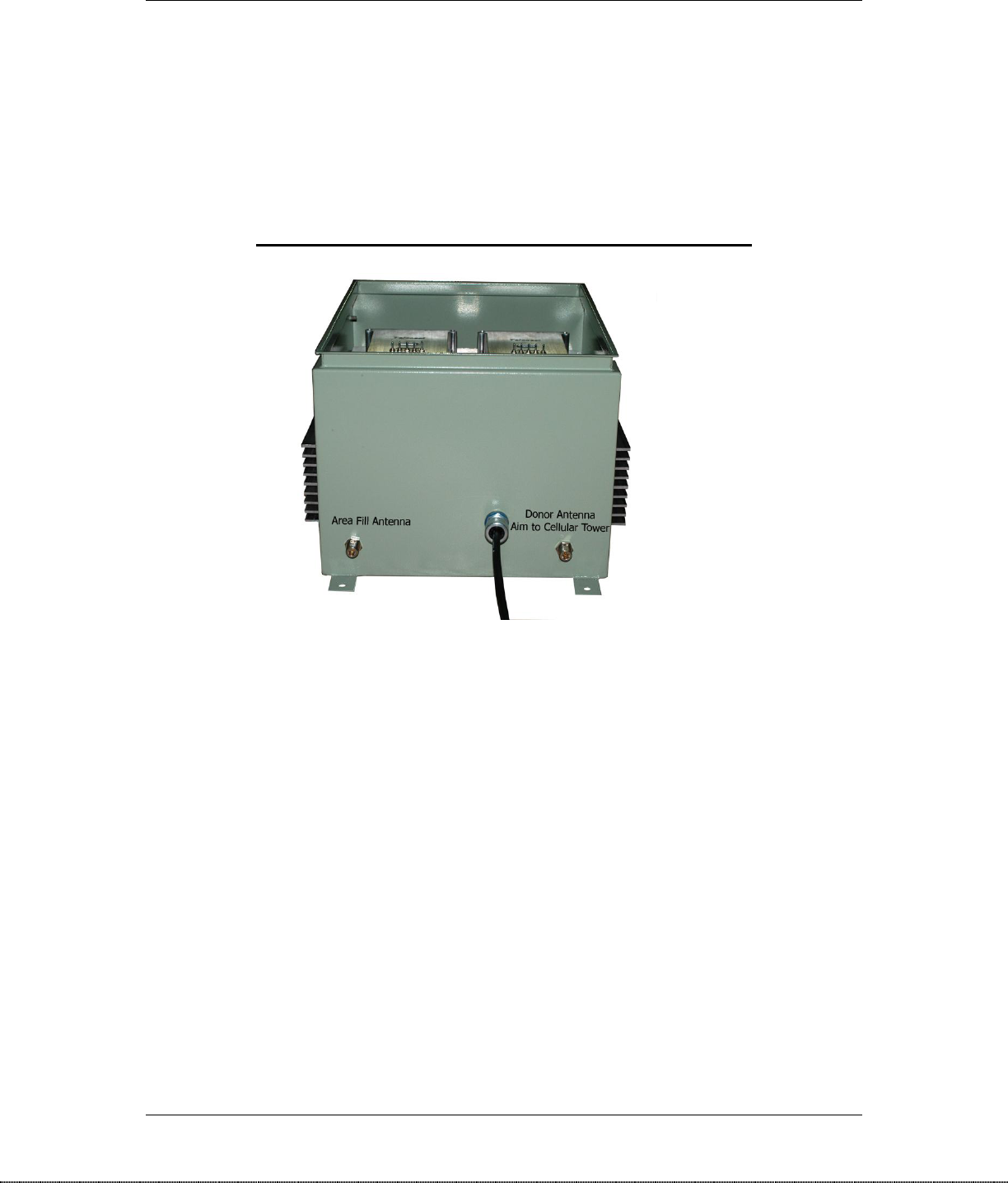
TELCOSAT RPT 1900
Document use is restricted to that described on cover 1-2
Bottom of enclosure showing antenna connections
Figure 4
Only when you have safely connected and installed your antennas, coax, and securely mounted
your Repeater enclosure can you then proceed to the next step.
Open the enclosure door and you will see two rows of 5 toggle switches and one larger toggle
switch for the power on/off.
Ensure the power toggle switch is in the off position.
Ensure the 2 rows of five toggle switches are toggled to the up position. Toggle all switches up.
ELECTRICAL POWER SUPPLY
Consult a qualified electrician to verify correct power/voltages and that the repeater enclosure is
properly grounded according to the rules and regulations of your country. The power cord plug is
a 3 pin male type plug. One of the pins on this power cord plug must be a grounded pin. The
power cord plug must properly match the plug in receptacle.
Ensuring the above is completed connect the repeater to the power supply. Open the RPT1900
enclosure door and toggle the power switch to the on position. The red light will illuminate when
the repeater is power on.

TELCOSAT RPT 1900
Document use is restricted to that described on cover 1-2
3.6 MANUAL RF GAIN ADJUSTMENT
Open the door on the Repeater and you will see two modules with a row of switches on each
Module. These switches allow for 50dB of manual RF gain adjustment in 2 dB increments.
The left side row of switches marked 1850MHz to 1910MHz, controls the power level that
transmit back to the cellular tower. The right side row of switches marked 1910MHz to
1990MHz controls the power levels to your area fill.
A symbol to the right of the row of switches display – (negative) and + (positive). If the switch
is in the – (negative) position the power is reduced by the appropriate number below the switch. If
the switch is in the + (positive ) position then the power is increased by the appropriate number
below the switch. All the numbers below the switches are in dB
The rows of switches have numbers below each switch. The numbers are in dB and each number
accurately represents the value displayed. For example, the number 20 below the switch
represents 20dB of gain if the switch is in the down position and a reduction of 20 dB of gain if
the switch is in the up position.
NOTE: Your RPT1900 has a maximum gain of 90dB. The manual gain adjustment has a
range of 50dB in 2 dB increments. When all the switches are in the up position
– (negative) your repeater is still operating with signal gain. 90dB – 50dB of manual
adjustment = 40dB. Your repeater has 40dB of gain when all the switches are in the
–(negative) position.

TELCOSAT RPT 1900
Document use is restricted to that described on cover 1-2
3.7 RSSI METER AND SIGNAL LEVELS
Your Repeater is fitted with a green bar graph LED; RSSI (Receive Signal Strength Indicator)
Your RSSI indicator is located just above your row of Manual RF Gain Switches.
(NOTE: THE RSSI INDICATOR DISPLAYS RECEIVE SIGNAL STRENGTH ONLY. THEY
DO NOT DISPLAY TRANSMIT POWER.)
The RSSI indicator has a dynamic range of -80 dBm to – 65dBm.
The green Led’s display will start to illuminate when a signal strength of -80dBm or greater is
received. When aligning your antenna to the cellular tower the RSSI meter can be monitored to
assist in the process. When you rotate your antenna you will see the RSSI indicator LED light up
as you pass the signal with your antenna.
If you’re incoming RF signal is below -80dB then your RSSI indicator will not illuminate. At this
point, installation will require an RF Spectrum Analyzer to assist in the antenna alignment.
3.8 ALIGNING YOUR DONOR ANTENNA TO A CELLULAR TOWER
To maximize the full benefit of your RPT 1900 the end user should consult an RF
engineer or RF/Radio technician to properly size your antenna and coax cable prior
to installation. Incorrect input signal levels can result in reduced RF signal
coverage.
Further engineering assistance can be obtained from Telcosat Inc
Align your antenna with the cell tower (Donor). If the Donor signal strength is greater than
-80dBm the LED window on the Donor side will start to illuminate. Adjust the antenna until the
received signal is peaked.
After adjusting the receive signal levels from the Cellular Tower we now adjust the power levels
for the area fill. (Down-Link Signal)
For the next step you can use your cellular phone signal level indicator or preferably an RF
Spectrum Analyzer.
Toggle down the area fill switches in 2dBm steps until the desired power levels have been
obtained.

TELCOSAT RPT 1900
Document use is restricted to that described on cover 1-2
3.9 ADJUSTING UP-LINK (Reverse Link) TRANSMIT POWER TO CELLULAR
TOWER
It is important to only use the minimum required power level for the Up-Link also
known as the “Reverse Link” transmit power.
The required power level setting can be provided from a RF Systems Engineer or
appropriate RF Path Loss calculations.
Make a test call while the repeater is adjusted to the minimum gain on the Uplink Frequency
(1850/1910 MHz)
When making the test call on your cellular phone you must be a minimum of 30 metres (100ft)
from the area fill antenna.
If you cannot complete the call increase power in 2 dBm increments. Make a test call after every
adjustment.
Help Notes.
If you find that you cannot detect any cellular signals using the RSSI indicator then
you must use an alternative method to locate the signal, for example a good quality
RF Spectrum Analyzer.
If you fail to locate a signal then you have the following possibilities.
1) There is no cellular service.
2) Faulty coax, connectors or antenna.
3) Insufficient antenna separation, (vertical separation/ horizontal separation)
4) Aimed to a competitor’s cell tower which does not service your cellular phone. This may show
full power on your cellular phone but will not connect to the service.
FOR TECHNICAL ASSISTANCE INSTALLING YOUR REPEATER PLEASE
CONTACT:
Telcosat Inc,
Calgary, Alberta,
Canada.
T2E 7E4
Canada 403 291 4031
Canada Fax 403 291 3059
Email: inquiries@telcosat.com
NOTE: Local time, Central Mountain Time. (-7 GMT)

TELCOSAT RPT 1900
Document use is restricted to that described on cover 1-2
CHAPTER 4
WARRANTY AND REPAIR
4.1 WARRANTY
Your Telcosat Repeater is guaranteed against manufacturers defects for 24 months (Two Years)
for permanent fixed installations only. Warranty includes parts and labour only. Warranty does
not include shipping/freight costs.
Telcosat Inc retains the right to decide if the fault/defect is a manufacturer’s defect.
Telcosat Inc will not accept liability for any damage caused through improper use or poor
installation practices.
4.2 Limited Warranty
Telcosat Inc, or any authorized subsidiary selling the Product (RPT1900 Cellular Repeater)
warrants that commencing from the date of shipment to the Customer for a period of 24 calendar
months, the hardware will be free from defects in material and workmanship under normal use on
permanent fixed installations only. Warranty includes parts and labour only. Warranty does not
cover freight costs.
The date of shipment of a Product by Telcosat Inc is set forth on the packaging material in which
the Product is shipped. This limited warranty extends only to the original user of the Product.
Customer's sole and exclusive remedy and the entire liability of Telcosat Inc and its suppliers
under this limited warranty will be the repair, parts and labour included, at Telcosat Inc or a
designated Telcosat service center. Freight costs will not be accepted by Telcosat Inc. Customer
to pre-pay the shipping costs.
EXCEPT AS SPECIFIED IN THIS WARRANTY, ALL EXPRESS OR IMPLIED CONDITIONS,
REPRESENTATIONS, AND WARRANTIES INCLUDING, WITHOUT LIMITATION, ANY
IMPLIED WARRANTY OR CONDITION OF MERCHANTABILITY, FITNESS FOR A
PARTICULAR PURPOSE, NON-INFRINGEMENT, SATISFACTORY QUALITY, NON-
INTERFERENCE, ACCURACY OF INFORMATIONAL CONTENT, OR ARISING FROM A
COURSE OF DEALING, LAW, USAGE, OR TRADE PRACTICE, ARE HEREBY EXCLUDED
TO THE EXTENT ALLOWED BY APPLICABLE LAW AND ARE EXPRESSLY DISCLAIMED
BY TELCOSAT INC, ITS SUPPLIERS AND LICENSORS. TO THE EXTENT AN IMPLIED
WARRANTY CANNOT BE EXCLUDED, SUCH WARRANTY IS LIMITED IN DURATION TO
THE EXPRESS WARRANTY PERIOD. BECAUSE SOME STATES OR JURISDICTIONS DO
NOT ALLOW LIMITATIONS ON HOW LONG AN IMPLIED WARRANTY LASTS, THE
ABOVE LIMITATION MAY NOT APPLY. THIS WARRANTY GIVES CUSTOMER SPECIFIC
LEGAL RIGHTS, AND CUSTOMER MAY ALSO HAVE OTHER RIGHTS WHICH VARY
FROM JURISDICTION TO JURISDICTION. LEGAL ACTION AGAINST TELCOSAT INC,
SHARE HOLDERS OF TELCOSAT INC, DIRECTORS, AGENTS CONSULTANTS OR
EMPLOYEES OF TELCOSAT INC, WILL BE DEFENDED THROUGH THE LEGAL
PROCESS/COURTS IN THE PROVINCE OF ALBERTA, CANADA. This disclaimer and
exclusion shall apply even if the express warranty set forth above fails of its essential purpose.
Restrictions. This warranty does not apply if the Product or any other equipment upon which the
Product is authorized to be used (a) has been altered, except by Telcosat Inc, (b) has not been
installed, operated, repaired, or maintained in accordance with instructions supplied by Telcosat
Inc, (c) has been subjected to abnormal physical or electrical stress, misuse, mobile applications,

TELCOSAT RPT 1900
Document use is restricted to that described on cover 1-2
non- permanent sites, negligence, accidents forces of nature, earthquakes, lightning strikes,
vandalism, and civil unrest.
CHAPTER 5.
Long Term Storage of Equipment
When storing your equipment you must place the unit in a dry location, away from direct
sun exposure and take measures to prevent moisture/condensation build up in your
repeater enclosure.
Silica Gel bags should be placed inside the enclosure to absorb moisture. The door on
the enclosure should be closed and sealed with weather proof tape to ensure an air tight
enclosure.
The silica gel bags should be changed /inspected at regular intervals to ensure proper
functionality of the material.
You are strongly advised to seek the advice of a professional company that has expertise
in long term preservation techniques of electronic equipment.
Maximum storage temperatures of your Telcosat Repeater is +60°C (122F)
Minimum storage temperature of your Telcosat Repeater is -40°C (-40F)

TELCOSAT RPT 1900
Document use is restricted to that described on cover 1-2
APPENDIX A
RETURNED GOODS PROCEDURE
A1. Technical Information
Contact Telcosat Inc or your supplier to determine whether or not an item should be returned for
repair.
Contact Telcosat Inc Canada 403 291 4031 or email, inquiries@telcosat.com
A2. Return Identification
Please provide the following information with each repair.
1. Date of requested repairs.
2. Customer name with full address for returning goods
3. Contact person responsible for returning the product for repairs
4. Client telephone number
5. Serial number (serial number is located on the exterior heat sink)
6. Original purchase date
7. Reason for return.
A3. Shipping Procedure
Ship all returned goods PREPAID to the following address:
Product Repairs,
Telcosat Inc,
Bay 116, 1919 – 27th Avenue NE,
Calgary, Alberta,
Canada. T2E 7E4
Telephone Canada 403 291 4031
Fax Canada 403 291 3059
Email: inquiries@telcosat.com
Your commercial invoice must state REPAIR/RETURN. Failure to provide proper Commercial
Invoices may result in taxes and duties which will be charged back to the client.
A4. Return Shipments
All returned shipments will be sent PREPAID, to the customer’s indicated address.
Any extra packaging material will be charged back to the client.
A5. Repair / Return Status

TELCOSAT RPT 1900
Document use is restricted to that described on cover 1-2
Under normal circumstances defective items will be replaced repaired with in 5 working business
days of receipt.
Telcosat Inc will inspect and test your repeater in a lab environment. Upon completion of the
inspection a written estimate will be provided to the client. A minimum charge of $500.00 will be
charged to the client to cover the cost of inspection and testing plus minor repairs.