Teldat ESCG0408 802.11 a/b/g WLAN-Client Adaptor and Bridge User Manual ESCG FEC Manual en 215
Teldat GmbH 802.11 a/b/g WLAN-Client Adaptor and Bridge ESCG FEC Manual en 215
Teldat >
UserMan
ESCG Manual Version 2.15 1
ESCG
802.11 a/b/g
WLAN-Client Adaptor and Bridge
Manual
ESCG Manual Version 2.15 2
Content:
Overview ............................................................................................................................................................ 3
Technical features:......................................................................................................................................... 5
WLAN - Interface:........................................................................................................................................... 5
First Time Setup ................................................................................................................................................ 6
The ESCG-Config Program ........................................................................................................................... 6
Reset to factory default .................................................................................................................................. 7
Parameter setting via WEB interface................................................................................................................. 7
Information page ............................................................................................................................................ 7
Access Point page ......................................................................................................................................... 9
Security page ............................................................................................................................................... 11
Admin page .................................................................................................................................................. 12
Advanced page ............................................................................................................................................ 13
Cloning ..................................................................................................................................................... 13
Advanced bridging.................................................................................................................................... 13
Roaming ................................................................................................................................................... 13
Ethernet Port ............................................................................................................................................ 13
DHCP-Relay-Agent .................................................................................................................................. 13
Serial interface setup ................................................................................................................................... 15
Comment to the multicast settings ........................................................................................................... 16
Power supply connector............................................................................................................................... 19
Pictures:
Illustration 1 Block schematic ............................................................................................................................ 3
Illustration 2 Connections and LEDs ................................................................................................................. 4
Illustration 3 arrangement to configure the ESCG............................................................................................. 6
Illustration 4 screenshot of the ESCG-Config-Program..................................................................................... 6
Illustration 5: Information page .......................................................................................................................... 8
Illustration 6: Access Point page ....................................................................................................................... 9
Illustration 7: Wireless page............................................................................................................................. 10
Illustration 8: Security page ............................................................................................................................. 11
Illustration 9: Administration page ................................................................................................................... 12
Illustration 10: Advanced page ........................................................................................................................ 14
Illustration 11: Windows TCP/IP port monitor.................................................................................................. 15
Illustration 12: Multicast-mode......................................................................................................................... 16
Illustration 13: Serial interface setup ............................................................................................................... 18
Illustration 14 Power supply connector............................................................................................................ 19
ESCG Manual Version 2.15 3
Overview
The ESCG is intended to connect devices with ethernet or serial interfaces to a Wireless Local Area Network
(WLAN) corresponding to the 802.11 a/b/g standard. The ESCG connects over the ethernet interface all
devices in its LAN segment with a LAN that is accessible over WLAN.
The ESCG can receive and transmit data over its serial port which are exchanged over LAN or WLAN with
other devices, i.e. annother ESCG or a computer with a suitable software.
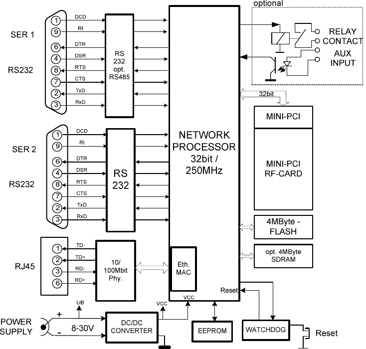
Functional blocks:
Illustration 1 Block schematic
The core of the ESCG is a 32bit network processor that controls all functions.
The interfaces:
1) Mini-PCI-Socket
2) Ethernet-Interface 10/100 MBit + auto MDI (auto crossover function)
3) 1 or 2 serial interfaces with 6 status lines each
4) optional: Relay contact and AUX input with optocouple
ESCG Manual Version 2.15 4
The ethernet port has a RJ45 input. Because of the auto MDI functionality the ESCG can be attached to a
HUB or the LAN port of a computer with standard patch cables. The ESCG recognizes the cable polarity and
automatically connects the right signal lines.
The serial port is a 9 pin female D-SUB connector. The pinout makes it possible to connect to a computer
COM port with a 1 to 1 serial cable, the exact pinout is shown in Illustration 1 above.
The power supply should be 8 – 30VDC / 3W. At 12VDC the input current is 250mA.
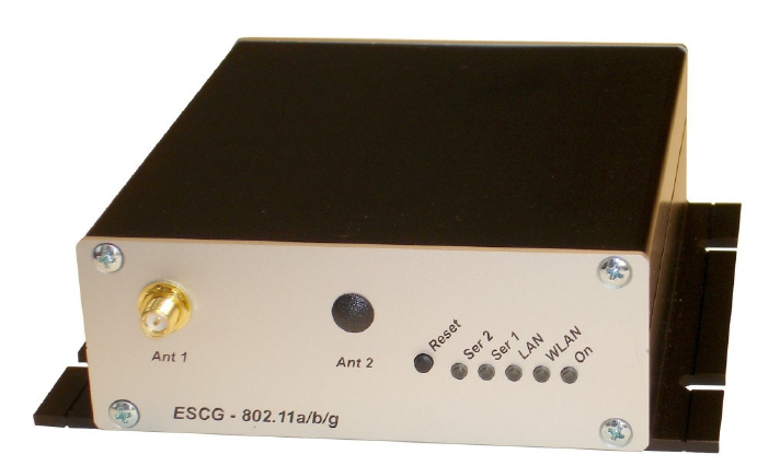
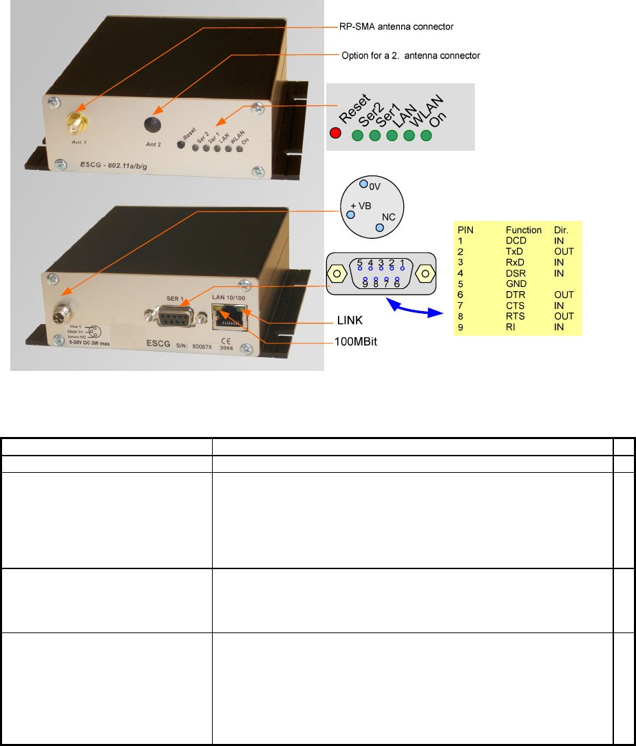
Back and front view:
Illustration 2 Connections and LEDs
LED Function
On Green always on when power is on
WLAN Red blinking searching for RF-connection (scanning)
Steady green found a suitable Access-Point and established
a connection
Green blinking 802.1x Authentification is in process
Green + red blinking
RF activity (receive or transmit)
LAN Off no link is recognized
Green link is established with another LAN device.
Green + red blinking
activity on the LAN interface
Ser1 (2) Off interface is inactive or not connected to the
other (W)LAN-.communication side
Green connected to other serial device.
Green + red blinking
activity on the serial interface (receive or
transmit)

ESCG Manual Version 2.15 5
Technical features:
Processor Type 32bit network processor 250MHz clock
Memory 256KByte program (internal)
64KByte data (internal)
4MByte flash (external)
4MByte SDRAM (external, optional)
Interface Ethernet 10/100 Mbps fast ethernet auto MDI/MDIX
Serial 1 RS232 with control lines
RTS, CTS, DSR, DTR,DCD (input), RI (input)
(optional as RS485, RS422)
Serial 2 Same as serial 1 but only RS232
Mini-PCI Socket for RF cards with Atheros chipsets
(AR5112, AR5113)
Relay (optional) Relay contact
can be operated over LAN or WLAN
Connection with circular M8-4pin connector
AUX input (optional) Isolated input with optocouple
LEDs LEDs - Power (green)
- WLAN (green, red)
- LAN (green, red)
- SER1 (green, red)
- SER2 (green, red)
Power supply Connector Standard: DC jack (2.1mm pin / 5.5mm hole)
optional: Circular M8-3pin connector with screw locking
Power consumption < 2.5W (typ.) < 3W (max.)
Voltage range Standard: 8-30V non isolated
optional: 18-72V or 9-36V isolated
Temperature
range
operating 0 - 70°C ( 32 - 158°F)
storage -20 - 80°C ( -4 - 176°F)
Dimensions Board 120x100x20mm
Case standard: 125x105x40mm
Weight approx. 500g
WLAN - Interface:
WLAN Encryption 64, 128bit WEP, AES
Security 802.11i WPA + WPA2 (Wifi Protected Access) (PSK/TKIP)
802.1x (EAP-TLS, EAP-PEAP), LEAP
Data rates
802.11b 11, 5,5, 2 & 1 MBit/Sec.
802.11g 54, 48, 36, 24, 18, 12, 9, 6 MBit/Sec.
802.11a 54, 48, 36, 24, 18, 12, 9, 6 MBit/Sec.
Frequencies
ISM band: 2.400 MHz to 2.483 MHz
U-NII band: 5.150 MHz to 5.350 MHz (ETSI, RegTP indoor)
5.470 MHz to 5.725 MHz (ETSI, RegTP outdoor)
Channels 802.11b/g:
ETSI: 1-13, (3 non overlapping)
802.11a:
ETSI: 12 non overlapping (5.150-5.350 & 5.470-5.725 MHz)
Power output 802.11b/g: 18dBm peak
802.11a: 18 or 17dBm
ESCG Manual Version 2.15 6
First Time Setup
To set up the ESCG it has to be connected with a patchcable to the ethernet interface of a computer.
Because of the auto MDI/MDIX capability, you can use a straight or crossover patchcable.
After applying power, the green “Link LED“ on the RJ45 connector shines when a link is detected. The yellow
“100 MBit LED“ indicates whether the connection is capable of 100 MBit.
The “LAN” LED on the front panel shines green when a connection has been established over the ethernet.
The “WLAN” LED on the front panel will be blinking red because usually no suitable WLAN is recognized.
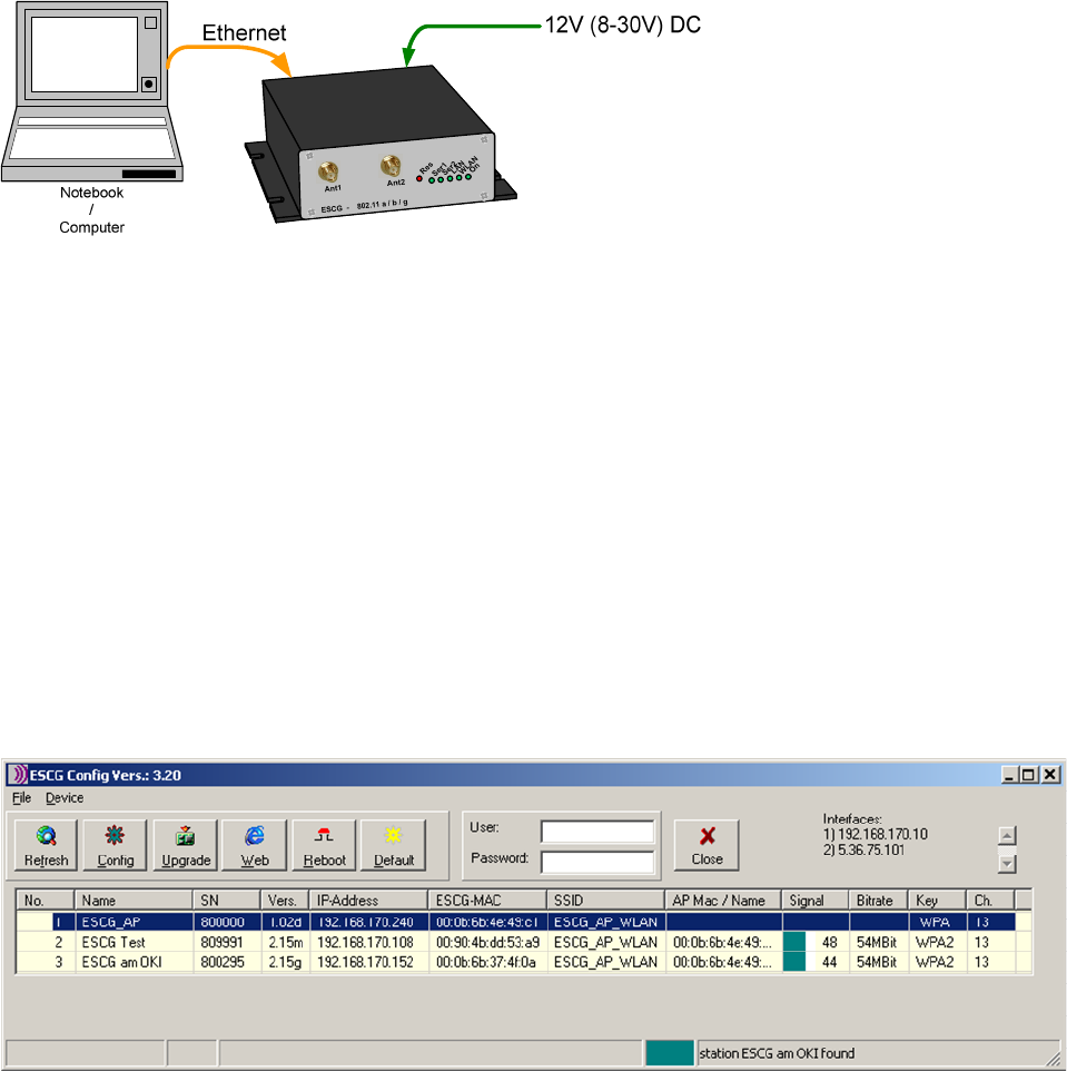
The ESCG-Config Program
To do the „first time setup“ the ESCG has to be connected via the LAN-Interface to the computer (PC) that
runs the ESCG-Config-Program.
Illustration 3 arrangement to configure the ESCG
You have to observe:
- The connected PC should have an fixed IP address. (no DHCP)
- The LAN-Interface at the PC must be detected as connected. Check the parameter of the LAN-
Interface with the „ipconfig“-command.
- If the LAN-Interface of the PC is correctly recognized then press the „refesh“-button of the ESCG-
config-program.
- An active firewall could prevent the communication the ESCG.
After the start the ESCG-Config-Program ascertained all network interfaces that are active at the PC. After
that the ESCG-Config-Program sends broadcast UDP requests to all these Interfaces. The registered
answers of the ESCG devices are shown in a list.
Illustration 4 screenshot of the ESCG-Config-Program
ESCG Manual Version 2.15 7
All located ESCG-Devices are shown in list with there station names, firmware versions and addresses. The
WLAN connection is also shown with a signal quality value.
The value can be interpreted as follows:
Signal >= 40 connection very good
Signal >= 30 connection good
Signal >= 20 connection is ok, but the ESCG starts to search for better AP’s.
Signal < 20 connection restricted, the bit rates will be lowered.
Reset to factory default
The factory default settings can be restored by pressing the reset button located on the front panel for a
longer period. After about 5 seconds the LEDs “SER1“ and “SER2“ starts blinking red and green alternately.
By keeping the button depressed the factory default values are restored. After finishing all LEDs except the
“ON” LED are turned off. Now the reset button can be released.
main factory default values:
SSID = “ESCG_WLAN“
WEP = OFF
WPA = OFF
MODE= 802.11b/g
IP = 192.168.178.100
Netmask = 255.255.255.0
SER1+2 : off
802.1x user: „admin“
802.1x password: „password“
Parameter setting via WEB interface
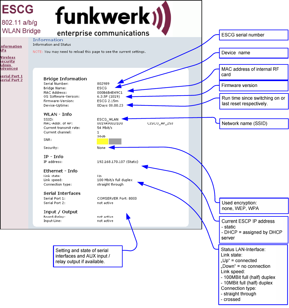
Information page
General information regarding firmware versions and status reports
ESCG Manual Version 2.15 8
Illustration 5: Information page
On the left hand side are links to different setup and info pages.
• Information the page above(Illustration 5)
• APs Shows a table with all access points currently seen by the ESCG (Illustration 6).
• Wireless WLAN interface setup (SSID, mode, frequencies etc.) (Illustration 7)
• Security Encryption setup (WPA, WEP) (Illustration 8)
• Admin - reboot ESCG
- reset all parameters to default.
- firmware updates
- configure IP-address, subnet mask, gateway IP
- configure setup options
ESCG Manual Version 2.15 9
- enter username and password
(Illustration 9)
• serial Port 1 setup of serial port 1 (Illustration 13)
• serial Port 2 setup of serial port 2
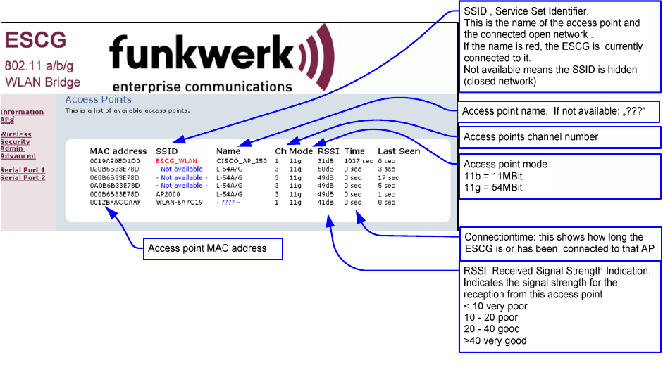
Access Point page
Information on all access points currently available to the ESCG.
Illustration 6: Access Point page
ESCG Manual Version 2.15 10
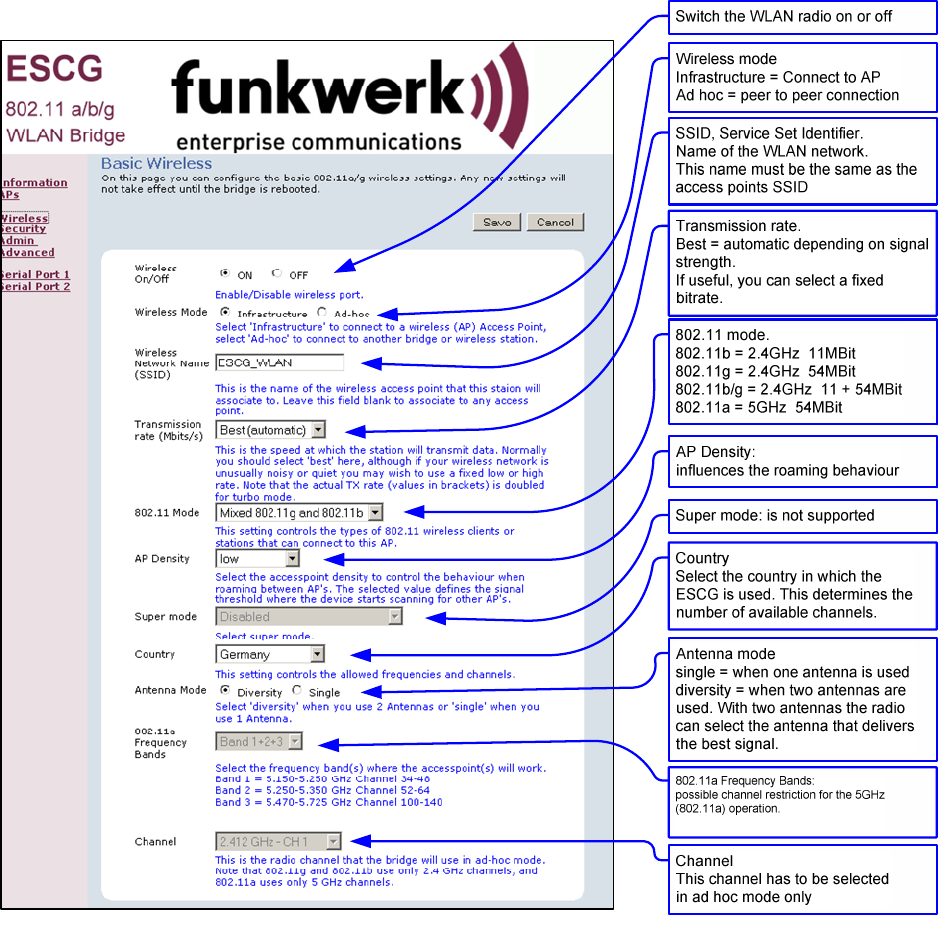
Wireless page
Configuring the WLAN interface
Illustration 7: Wireless page
By clicking the “Save“ button all changes on this page are stored. Use “Cancel” to undo any changes. After
clicking “Save” the program prompts the user to make a reboot. This should be done after all necessary
changes on all pages have been made.
ESCG Manual Version 2.15 11
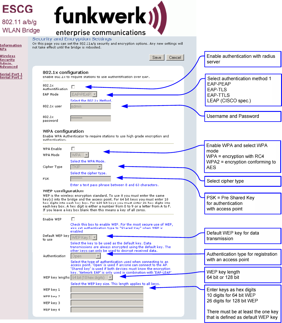
Security page
Setting up the security options
If the user selects the 802.1x authentication the PSK or the WEP-Keys don’t have to be defined because the
ESCG and the Radius-Server will determine these parameters automatically.
Illustration 8: Security page
ESCG Manual Version 2.15 12
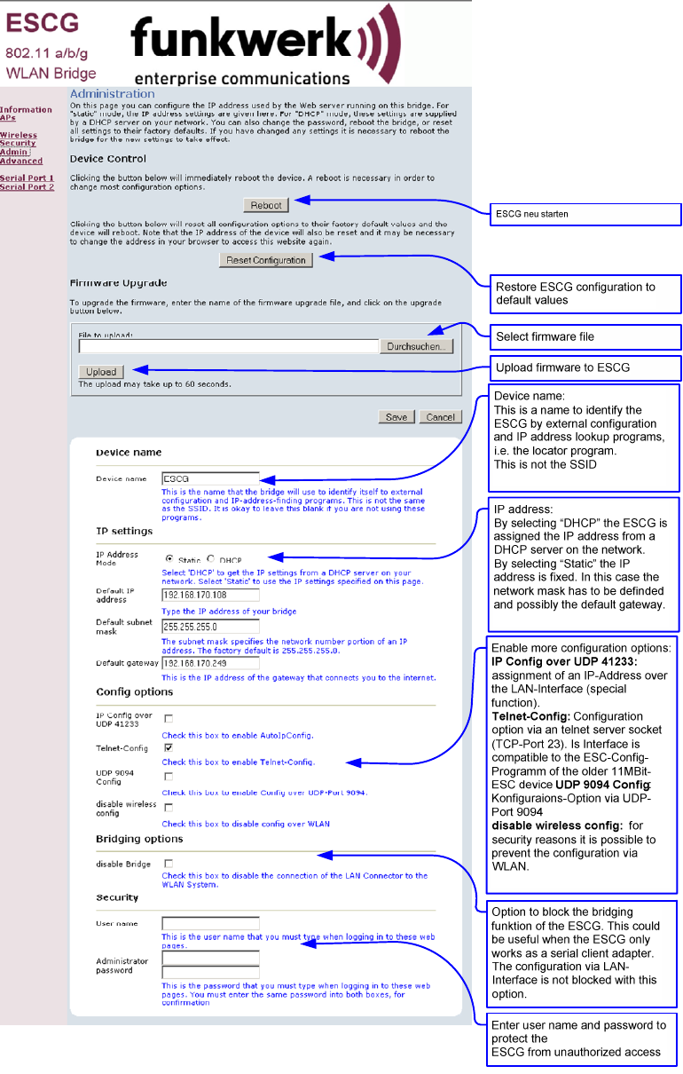
Admin page
Setting up administration rights and configure basic features, update firmware
Illustration 9: Administration page
ESCG Manual Version 2.15 13
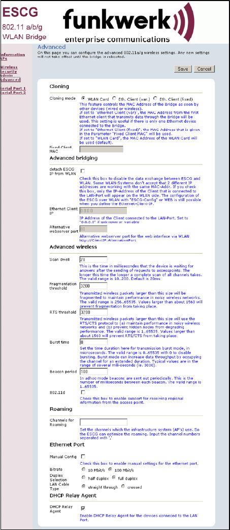
Advanced page
The advanced page offers more detailed options to define the behaviour of the ESCG in the WLAN
environment.
Cloning
The cloning parameter defines the MAC address of the ESCG’s radio. Usually the ESCG leaves the MAC
address at the manufacturers value. All devices connected to the WLAN over the ESCG’s ethernet port use
this MAC address for communication.
The ESCG keeps a table where the original MAC address of the connected device is linked to its IP address.
If a data package arrives at the ESCG on the ethernet port, the ESCG first checks if there is an entry in its
table with the source MAC address of this device. If the answer is no, this MAC address is added to the
table.
Next it checks if there is an entry for the target MAC address.
If the answer is yes it means that the receiver of this data packet is located on the wired side of the ESCG
and therefore there is no need to send it over the wireless radio.
If the answer is no, the source MAC address is replaced by the radio’s MAC address and the data package
is sent over the radio to the WLAN
If the ESCG receives a data package from the WLAN, it first extracts the target IP address. Next it looks up
the corresponding MAC address in its table. This MAC address is placed in the data package which is then
sent over the ethernet port to the connected devices.
With this method several devices can be connected to the ESCG.
This procedure only works in LAN’s / WLAN’s that use the IP protocol. If other protocols are used, the ESCG
can be forced to transfer the MAC address of the first data packet that arrives on the ethernet port to the
radio. This method is called cloning. It ensures that all data packages intended for the connected device are
received by the ESCG. The ESCG can forward the data to the ethernet port without any further processing.
This method allows only one device to be connected to the ESCG ethernet port. This strategy is activated by
selection the option “Eth. Client (var)”.
With the option “Eth. Client (fixed)” the user can defined a MAC address that the ESCG will use for the
WLAN Connection.
Advanced bridging
Check this box to disable the data exchange between ESCG and WLAN. Some WLAN-Systems don't accept
that 2 different IP addresses are working with the same MAC-Address. If you check this box, only the IP-
Address of the Client that is connected to the LAN-Port will appear on the WLAN side. The configuration of
the ESCG over WLAN is not possible with this setting.
Roaming
Roaming is the term for automatically changing to another access point when the ESCG recognizes a
decreasing RF signal level when leaving the covered area of the current access point and a better level with
another AP available.
For this purpose the ESCG keeps a table with a list of access points from which it is receiving signals
(beacons).
To receive these beacons the ESCG has to tune to the different channels and listen for incoming signals for
a certain amount of time. This hampers the regular data traffic which the ESCG has to process. Therefore
this procedure is handled in different ways depending on the current signal level.
To make this procedure even more effective, the user can restrict the channels where the ESCG is allowed
to look for beacons of other access points
Ethernet Port
Check this option to enable manual settings for the ethernet port.
DHCP-Relay-Agent
Check this option to enable the DHCP-Relay-Agent of the ESCG. This is useful if the connected clients at
the ethernet port of the ESCG are using DHCP.
ESCG Manual Version 2.15 14
Illustration 10: Advanced page
ESCG Manual Version 2.15 15
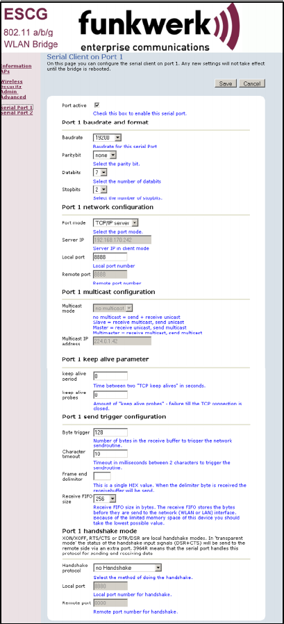
Serial interface setup
The ESCG can have one or two serial interfaces, depending on the options. Each interface is configured on
its own WEB page.
Network configuration
There are different modes available for the use of the serial interfaces:
1) TCP/IP server mode:
In this mode the ESCG opens a socket in a “listen mode”, which means that it is waiting on a certain port
(local port) for a connection. The ESCG only holds one connection at a time. In this mode only the port
number has to be specified.
2) TCP/IP client mode:
In this mode the ESCG actively opens a TCP connection on the specified port of another network node.
This node can be another ESCG or a computer which is waiting for a connection on the specified port. In
this mode the port number and the IP address of the connected device have to be specified.
3) UDP/IP mode:
In this mode the ESCG is waiting for data on the “local port“ which are sent with UDP/IP. The received
data are then sent to the “remote port” of the remote IP address. The UDP should be used in
circumstances where the communication between the devices is frequently interrupted. It should be
considered though that the UDP protocol does not guarantee the correct transfer of data.
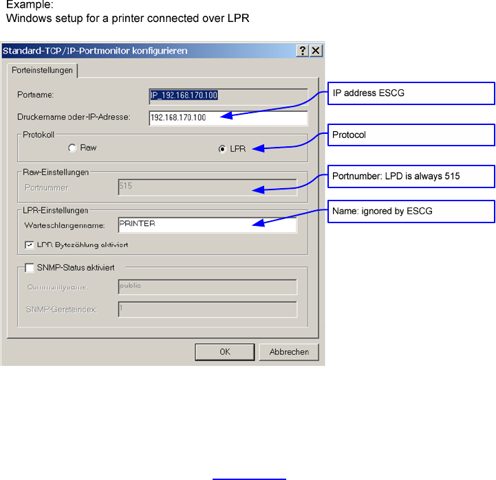
4) Printerserver mode:
In this mode the ESCG starts a TCP/IP socket in server mode which is waiting for a connection on port
515. The ESCG is then able to execute print jobs corresponding to RFC1179. If you want to enable a
printer with this method under Windows, it has to be set up like the following example:
Illustration 11: Windows TCP/IP port monitor
5) COM server mode:
In this mode the ESCG provides virtual COM ports under Windows. For this purpose a software tool from
the company Wiesemann & Theis (www.wut.de) has to be installed. The tool is named “COM Umlenkung.
This tool enables the ESCG to connect to serial devices over LAN/WLAN. After installation of the
software enter the ESCG IP address and port number.
ESCG Manual Version 2.15 16
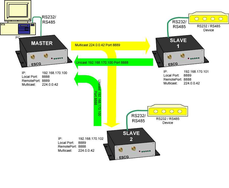
Comment to the multicast settings
In the Multicast-Mode serial busmembers who are communicating with RS485 interfaces can be connected
via the (W)LAN. Depending which task the serial device takes it is possible to configure different modes:
1. Slave
2. Master
3. Multimaster
As a slave the ESCG receives data on the configured multicast address and sends this data to the serial
interface. Data that is received from the serial line is sent to the given unicast IP address.
As a master the ESCG receives data from the unicast IP address and transmits data to the multicast IP
address.
In multimaster mode all transfers are done via the multicast IP address.
sample application:
Illustration 12: Multicast-mode
“Keep alive“ settings
A TCP/IP connection remains open after being established until one of the communicating devices closes
the connection. If the physical connection between the ESCG and the other device is interrupted without
closing the TCP/IP connection, there is a possibility that the ESCG is not able to reconnect. The TCP/IP
socket can be programmed to send an empty data package to the communication partner in regular intervals
(keep alive period). If the communication partner supports this mode, it sends a corresponding answer. This
answer is proof that the connection is still intact. If there is no answer for a number of times (keep alive
probes), the TCP/IP connection is closed and the ESCG starts the TCP/IP socket again.
“Send trigger” configuration
ESCG Manual Version 2.15 17
The data received by the ESCG are first temporarily stored. There are different criteria when the stored data
will be sent over the LAN/WLAN.
1) Byte trigger: The user defines a number of Bytes. After reaching that number, the stored data are
sent.
2) Timeout: After receiving a character a timer with the programmed value is started. Each received
character restarts the timer. Once the timer has elapsed the stored data are sent.
3) Delimiter: The user defines a certain character. When this character is received, the stored data are
sent.
The parameter “receive fifo size” defines the quantity of bytes that can be stored in a ringbuffer before the
data is sent to the (W)LAN interface. If you use the ESCG in an application that receives permanently data
via the serial interface the “receive fifo size” has to be set to a value between 1024 and 2048 bytes. Because
the ESCG needs all the available RAM memory in a situation of authentication with 802.1x (PEAP,TLS) this
value is set to a value of 256Bytes by default to save memory space.
Handshake mode
This defines how the communication partners are signalling their ability to send and receive data. With the
status lines RTS and DTR the ESCG reports that it is ready to receive. The status lines CTS and DTR are
inputs where the communication partner reports its readyness to receive. The signals DCD and RI can be
forwarded to the ESCGs LAN/WLAN communication partner.
The ESCG be controlled remote or local to handle the data flow.
The following modes are available to the user:
1) no handshake: The CTS/DSR signals are not utilized. CTS/RTS are set to active when the serial
interface is connected over the LAN/WLAN.
2) XON / XOFF : The ESCG sends and receives the control characters XON = 0x11 and XOFF = 0x13.
The ESCG sends a XOFF to his serial communication partner when the memory buffer is almost full
and a XON when it is almost empty.
3) RTS/CTS: The ESCG signals that it is ready to receive over the RTS line and recognizes the CTS
signal to determine if its serial partner is ready to receive.
4) DTR/DSR: The ESCG signals that it is ready to receive over the DTR line and recognizes the DSR
signal to determine if its serial partner is ready to receive.
5) Remote: In this mode the ESCG transmits the state of the status lines CTS, DSR, RI and DCD to its
LAN/WLAN communication partner. This happens over a different socket (port). This makes it
necessary for the user to enter more specifications.
The state of the status lines are described by strings of letters.
A capital letter means the signal is active, a small letter means inactive.
’D’ = DSR active ‘d’ = DSR inactive
’R’ = CTS active ‘r’ = CTS inactive
’C’ = DCD active ‘c’ = DCD inactive
’I’ = DSR active ‘i’ = DSR inactive
The ESCG interprets the received data as follows:
’D’ -> set DTR to active ‘d’ = set DTR to inactive
’R’ -> set RTS to active ‘r’ = set RTS to inactive
‘C’ or ‘c’ and ‘I’ or ‘i’ are ignored.
6) 3964R: This is a special protocol which is commonly used for communication with SPS
(programmable control systems). This protocol uses special characters and events to signal when it
is ready to transmit and receive. Descriptions of this protocol are available in literature.
ESCG Manual Version 2.15 18
Illustration 13: Serial interface setup
ESCG Manual Version 2.15 19
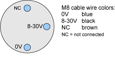
Power supply connector
Optional the ESCG can be equipped with a circular M8- 3pin connector. The connection is as follows:
Illustration 14 Power supply connector

Seite 2
Wireless LAN and your health
The Funkwerk Enterprise Communications Wireless LAN products, like other radio
devices, emit radio frequency electromagnetic energy. The level of energy emitted by
Wireless LAN devices however is far much less than the electromagnetic energy
emitted by wireless devices like for example mobile phones. Because Wireless LAN
products operate within the guidelines found in radio frequency safety standards and
recommendations, Funkwerk Enterprise Communications believes Wireless LAN is
safe for use by consumers. These standards and recommendations reflect the con-
sensus of the scientific community and result from deliberations of panels and com-
mittees of scientists who continually review and interpret the extensive research lit-
erature.
Federal Communication Commission
Interference Statement
NOTE: This equipment has been tested and found to comply with the limits for a
Class A digital device, pursuant to Part 15 of the FCC Rules. These limits are de-
signed to provide reasonable protection against harmful interference when the
equipment is operated in a commercial environment. This equipment generates,
uses, and can radiate radio frequency energy and, if not installed and used in accor-
dance with the instruction manual, may cause harmful interference to radio commu-
nications. Operation of this equipment in a residential area is likely to cause harmful
interference in which case the user will be required to correct the interference at his
own expense.
This device complies with Part 15 of the FCC Rules. Operation is subject to the fol-
lowing two conditions: (1) This device may not cause harmful interference, and (2)
this device must accept any interference received, including interference that may
cause undesired operation.
FCC Caution: Any changes or modifications not expressly approved by the party re-
sponsible for compliance could void the user's authority to operate this equipment.
The antenna(s) used for this transmitter must be installed to provide a separation dis-
tance of at least 20 cm from all persons and must not be co-located or operating in
conjunction with any other antenna or transmitter.
This device supports FCC Part 15, subpart E dynamic frequency selection (DFS cli-
ent without radar detection). For the band 5150–5250 MHz this equipment must be
used indoors only to reduce potential for harmful interference to co-channel mobile
satellite systems.
20