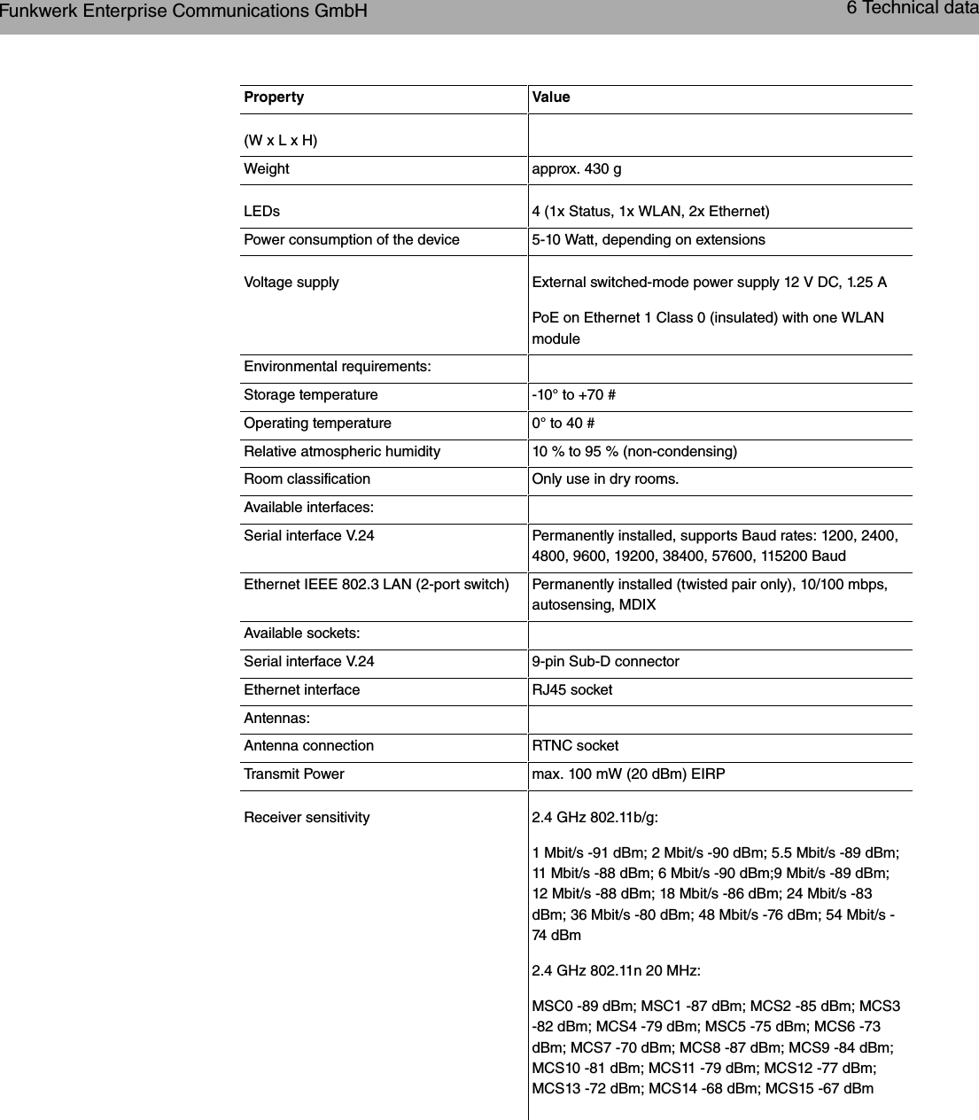
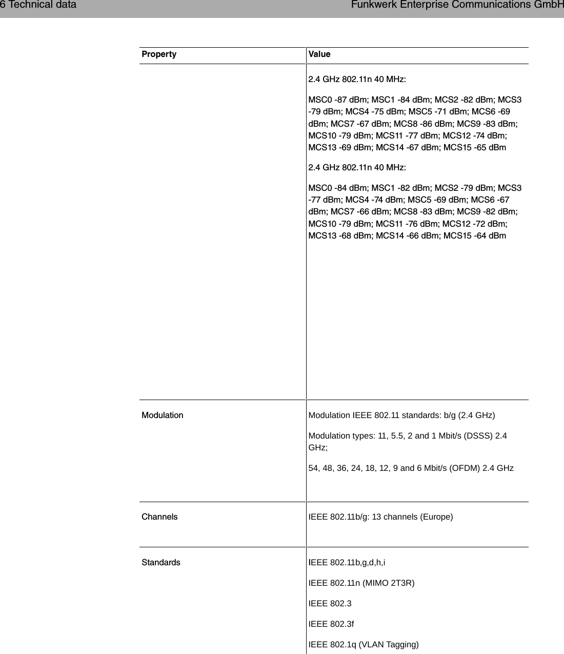
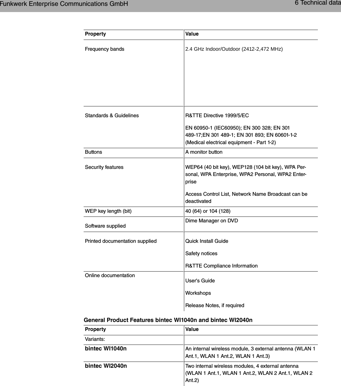
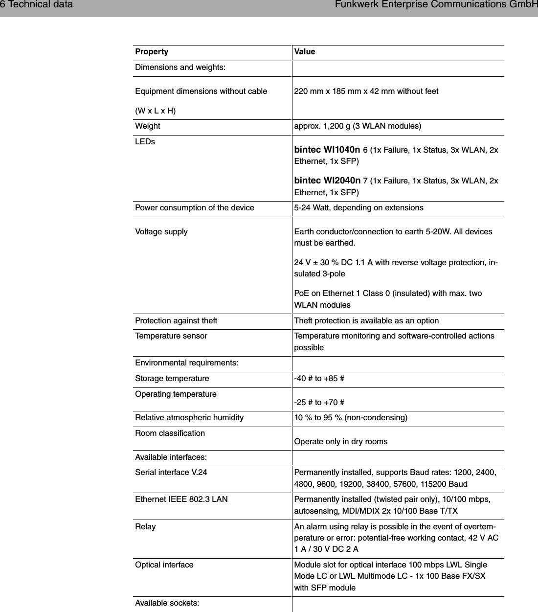
Teldat W1002N-080211 WLAN Access Point b/g/n User Manual W1002n UsMan

Teldat GmbH WLAN Access Point b/g/n W1002n UsMan

W1002n_UsMan

Manualbintec WLAN and Industrial WLANReferenceCopyright© Version 10.1, 2011 Funkwerk Enterprise Communications GmbHFunkwerk Enterprise Communications GmbH Manualbintec WLAN and Industrial WLAN 1
Legal NoticeAim and purposeThis document is part of the user manual for the installation and configuration of funkwerk devices. Forthe latest information and notes on the current software release, please also read our release notes,particularly if you are updating your software to a higher release version. You will find the latest releasenotes under www.funkwerk-ec.com .LiabilityThis manual has been put together with the greatest possible care. However, the information con-tained in this manual is not a guarantee of the properties of your product. Funkwerk Enterprise Com-munications GmbH is only liable within the terms of its conditions of sale and supply and accepts no li-ability for technical inaccuracies and/or omissions.The information in this manual can be changed without notice. You will find additional information andalso release notes for funkwerk devices under www.funkwerk-ec.com .Funkwerk devices make WAN connections as a possible function of the system configuration. Youmust monitor the product in order to avoid unwanted charges. Funkwerk Enterprise CommunicationsGmbH accepts no responsibility for data loss, unwanted connection costs and damage caused by un-intended operation of the product.Trademarksfunkwerk trademarks and the funkwerk logo, bintec trademarks and the bintec logo, artem trademarksand the artem logo, elmeg trademarks and the elmeg logo are registered trademarks of Funkwerk En-terprise Communications GmbH.Company and product names mentioned are usually trademarks of the companies or manufacturersconcerned.CopyrightAll rights reserved. No part of this manual may be reproduced or further processed in any way withoutthe written consent of Funkwerk Enterprise Communications GmbH. The documentation may not beprocessed and, in particular, translated without the consent of Funkwerk Enterprise CommunicationsGmbH.You will find information on guidelines and standards in the declarations of conformity underwww.funkwerk-ec.com .How to reach Funkwerk Enterprise Communications GmbHFunkwerk Enterprise Communications GmbH, Südwestpark 94, D-90449 Nuremberg, Germany,Phone: +49 911 9673 0, Fax: +49 911 688 07 25Funkwerk Enterprise Communications France S.A.S., 6/8 Avenue de la Grande Lande, F-33174Gradignan, France, Phone: +33 5 57 35 63 00, Fax: +33 5 56 89 14 05Internet: www.funkwerk-ec.comManual Funkwerk Enterprise Communications GmbH2 bintec WLAN and Industrial WLAN
Table of ContentsChapter1 Introduction...........................1Chapter 2 About this guide. . . . . . . . . . . . . . . . . . . . . . . . . 3Chapter3 Installation............................63.1 Setting up and connecting . . . . . . . . . . . . . . . . . . . . . . 63.2 Cleaning............................. 123.3 Support information . . . . . . . . . . . . . . . . . . . . . . . . 12Chapter 4 Basic configuration . . . . . . . . . . . . . . . . . . . . . . 144.1 Presettings ........................... 144.1.1 Preconfigured data . . . . . . . . . . . . . . . . . . . . . . . . 144.1.2 Softwareupdate......................... 154.2 System requirements . . . . . . . . . . . . . . . . . . . . . . . 164.3 Preparations........................... 164.3.1 Gatheringdata.......................... 164.3.2 ConfiguringaPC......................... 184.4 IPconfiguration.......................... 194.5 Modify system password. . . . . . . . . . . . . . . . . . . . . . 224.6 Setting up a wireless network . . . . . . . . . . . . . . . . . . . 224.7 Setting up a bridge link . . . . . . . . . . . . . . . . . . . . . . 234.8 SoftwareUpdate......................... 24Chapter5 Reset............................. 26Funkwerk Enterprise Communications GmbH Table of Contentsbintec WLAN and Industrial WLAN i
Chapter 6 Technical data . . . . . . . . . . . . . . . . . . . . . . . . 286.1 Scopeofsupply ......................... 286.2 General Product Features . . . . . . . . . . . . . . . . . . . . . 306.3 LEDs.............................. 396.4 Connectors ........................... 436.5 Antenna connectors for industrial WLAN devices with 802.11n support . 456.6 PinAssignments......................... 466.6.1 Ethernet interface. . . . . . . . . . . . . . . . . . . . . . . . . 466.6.2 Serialinterface.......................... 476.6.3 Socket for power supply . . . . . . . . . . . . . . . . . . . . . . 476.7 Frequencies and channels . . . . . . . . . . . . . . . . . . . . . 486.8 WEEEinformation ........................ 49Chapter 7 Access and configuration. . . . . . . . . . . . . . . . . . . 507.1 AccessOptions.......................... 507.1.1 AccessviaLAN ......................... 507.1.2 Access via the Serial Interface . . . . . . . . . . . . . . . . . . . 537.2 Loggingin............................ 557.2.1 User names and passwords in ex works state . . . . . . . . . . . . 557.2.2 Logging in for Configuration . . . . . . . . . . . . . . . . . . . . 567.3 Configuration options . . . . . . . . . . . . . . . . . . . . . . . 567.3.1 Funkwerk Configuration Interface for advanced users . . . . . . . . . 577.3.2 SNMPshell........................... 727.4 BOOTmonitor.......................... 72Chapter8 Assistants........................... 75Table of Contents Funkwerk Enterprise Communications GmbHii bintec WLAN and Industrial WLAN
Chapter 9 System Management . . . . . . . . . . . . . . . . . . . . . 769.1 Status.............................. 769.2 GlobalSettings.......................... 799.2.1 System............................. 799.2.2 Passwords............................ 829.2.3 DateandTime.......................... 839.2.4 SystemLicences......................... 879.3 Interface Mode / Bridge Groups. . . . . . . . . . . . . . . . . . . 909.3.1 Interfaces............................ 929.4 Administrative Access . . . . . . . . . . . . . . . . . . . . . . . 969.4.1 Access............................. 969.4.2 SSH .............................. 979.4.3 SNMP.............................. 1019.5 Remote Authentication . . . . . . . . . . . . . . . . . . . . . . 1029.5.1 RADIUS............................. 1029.5.2 TACACS+............................ 1089.5.3 Options............................. 1119.6 Certificates ........................... 1139.6.1 CertificateList.......................... 1139.6.2 CRLs.............................. 1229.6.3 Certificate Servers . . . . . . . . . . . . . . . . . . . . . . . . 123Chapter 10 Physical Interfaces . . . . . . . . . . . . . . . . . . . . . 12510.1 EthernetPorts.......................... 12510.1.1 Port Configuration . . . . . . . . . . . . . . . . . . . . . . . . 12510.2 SerialPort............................ 12710.2.1 SerialPort............................ 12710.3 Relay.............................. 131Funkwerk Enterprise Communications GmbH Table of Contentsbintec WLAN and Industrial WLAN iii
10.3.1 Relay Configuration . . . . . . . . . . . . . . . . . . . . . . . . 132Chapter11 LAN............................. 13311.1 IPConfiguration......................... 13311.1.1 Interfaces............................ 13311.2 VLAN.............................. 13711.2.1 VLANs ............................. 13911.2.2 Port Configuration . . . . . . . . . . . . . . . . . . . . . . . . 14011.2.3 Administration.......................... 141Chapter 12 Wireless LAN . . . . . . . . . . . . . . . . . . . . . . . . 14212.1 WLAN.............................. 14312.1.1 RadioSettings.......................... 14312.1.2 Virtual Service Sets . . . . . . . . . . . . . . . . . . . . . . . . 15712.1.3 WDSLinks............................ 16312.1.4 ClientLink............................ 16612.1.5 BridgeLinks........................... 17012.2 Administration.......................... 17912.2.1 BasicSettings.......................... 179Chapter 13 Wireless LAN Controller . . . . . . . . . . . . . . . . . . 18013.1 Wizard ............................. 18013.1.1 BasicSettings.......................... 18013.1.2 RadioProfile........................... 18113.1.3 Wireless Networks . . . . . . . . . . . . . . . . . . . . . . . . 18113.1.4 Start automatic installation . . . . . . . . . . . . . . . . . . . . . 18413.2 Controller Configuration . . . . . . . . . . . . . . . . . . . . . . 18513.2.1 General............................. 18613.3 Slave AP configuration . . . . . . . . . . . . . . . . . . . . . . 187Table of Contents Funkwerk Enterprise Communications GmbHiv bintec WLAN and Industrial WLAN
13.3.1 Slave Access Points . . . . . . . . . . . . . . . . . . . . . . . 18813.3.2 RadioProfiles.......................... 19213.3.3 Wireless Networks (VSS) . . . . . . . . . . . . . . . . . . . . . 19813.4 Monitoring............................ 20313.4.1 ActiveClients .......................... 20413.4.2 NeighborAPs.......................... 20513.4.3 Wireless Networks . . . . . . . . . . . . . . . . . . . . . . . . 20513.5 Maintenance........................... 20613.5.1 Firmware Maintenance . . . . . . . . . . . . . . . . . . . . . . 206Chapter14 Networking......................... 20814.1 Routes ............................. 20814.1.1 IPRoutes............................ 20814.1.2 Options............................. 21314.2 NAT............................... 21514.2.1 NATInterfaces.......................... 21514.2.2 NAT Configuration . . . . . . . . . . . . . . . . . . . . . . . . 21714.3 LoadBalancing.......................... 22114.3.1 Load Balancing Groups . . . . . . . . . . . . . . . . . . . . . . 22214.4 QoS .............................. 22514.4.1 QoSFilter............................ 22514.4.2 QoS Classification . . . . . . . . . . . . . . . . . . . . . . . . 22814.4.3 QoS Interfaces/Policies . . . . . . . . . . . . . . . . . . . . . . 23114.5 AccessRules .......................... 23714.5.1 AccessFilter .......................... 23914.5.2 RuleChains........................... 24214.5.3 Interface Assignment . . . . . . . . . . . . . . . . . . . . . . . 243Chapter 15 Routing Protocols. . . . . . . . . . . . . . . . . . . . . . 245Funkwerk Enterprise Communications GmbH Table of Contentsbintec WLAN and Industrial WLAN v
15.1 RIP............................... 24515.1.1 RIPInterfaces.......................... 24515.1.2 RIPFilter ............................ 24715.1.3 RIPOptions........................... 250Chapter16 Multicast........................... 25316.1 General............................. 25416.1.1 General............................. 25516.2 IGMP.............................. 25516.2.1 IGMP.............................. 25516.2.2 Options............................. 25816.3 Forwarding ........................... 25916.3.1 Forwarding ........................... 25916.4 PIM .............................. 26016.4.1 PIMInterfaces.......................... 26016.4.2 PIM Rendezvous Points . . . . . . . . . . . . . . . . . . . . . . 26316.4.3 PIMOptions........................... 264Chapter17 WAN............................. 26617.1 Internet+Dialup......................... 26617.1.1 PPPoE............................. 26817.1.2 PPTP.............................. 27317.1.3 IPPools............................. 27717.2 Real Time Jitter Control . . . . . . . . . . . . . . . . . . . . . . 27817.2.1 Controlled Interfaces . . . . . . . . . . . . . . . . . . . . . . . 279Chapter18 VPN............................. 28118.1 IPSec.............................. 28118.1.1 IPSecPeers........................... 281Table of Contents Funkwerk Enterprise Communications GmbHvi bintec WLAN and Industrial WLAN
18.1.2 Phase-1 Profiles . . . . . . . . . . . . . . . . . . . . . . . . . 28718.1.3 Phase-2 Profiles . . . . . . . . . . . . . . . . . . . . . . . . . 29518.1.4 XAUTHProfiles ......................... 29918.1.5 IPPools............................. 30218.1.6 Options............................. 30318.2 L2TP.............................. 30618.2.1 TunnelProfiles.......................... 30718.2.2 Users.............................. 31018.2.3 Options............................. 31618.3 GRE .............................. 31718.3.1 GRETunnels .......................... 317Chapter19 Firewall........................... 32019.1 Policies............................. 32119.1.1 FilterRules ........................... 32119.1.2 QoS .............................. 32519.1.3 Options............................. 32719.2 Interfaces............................ 32919.2.1 Groups............................. 32919.3 Addresses............................ 33019.3.1 AddressList........................... 33019.3.2 Groups............................. 33119.4 Services............................. 33219.4.1 ServiceList ........................... 33219.4.2 Groups............................. 334Chapter 20 Local Services . . . . . . . . . . . . . . . . . . . . . . . 33620.1 DNS .............................. 33620.1.1 GlobalSettings.......................... 33820.1.2 StaticHosts........................... 341Funkwerk Enterprise Communications GmbH Table of Contentsbintec WLAN and Industrial WLAN vii
20.1.3 Domain Forwarding . . . . . . . . . . . . . . . . . . . . . . . . 34220.1.4 Cache.............................. 34420.1.5 Statistics ............................ 34620.2 HTTPS............................. 34720.2.1 HTTPSServer.......................... 34720.3 DynDNSClient.......................... 34820.3.1 DynDNSUpdate......................... 34920.3.2 DynDNS Provider . . . . . . . . . . . . . . . . . . . . . . . . . 35020.4 DHCPServer .......................... 35220.4.1 DHCPPool ........................... 35320.4.2 IP/MACBinding ......................... 35520.4.3 DHCP Relay Settings . . . . . . . . . . . . . . . . . . . . . . . 35720.5 Scheduling............................ 35820.5.1 Trigger ............................. 35820.5.2 Actions............................. 36320.5.3 Options............................. 37420.6 Surveillance........................... 37520.6.1 Hosts.............................. 37620.6.2 Interfaces............................ 37820.6.3 PingGenerator.......................... 37920.7 Funkwerk Discovery . . . . . . . . . . . . . . . . . . . . . . . 38120.7.1 Device Discovery . . . . . . . . . . . . . . . . . . . . . . . . . 38120.7.2 Options............................. 38420.8 HotSpotGateway......................... 38520.8.1 HotSpot Gateway . . . . . . . . . . . . . . . . . . . . . . . . . 38720.8.2 Options............................. 390Chapter 21 Maintenance . . . . . . . . . . . . . . . . . . . . . . . . 39221.1 Diagnostics........................... 39221.1.1 PingTest............................ 392Table of Contents Funkwerk Enterprise Communications GmbHviii bintec WLAN and Industrial WLAN
21.1.2 DNSTest............................ 39321.1.3 Traceroute Test . . . . . . . . . . . . . . . . . . . . . . . . . 39321.2 Software &Configuration . . . . . . . . . . . . . . . . . . . . . . 39421.2.1 Options............................. 39421.3 Reboot............................. 39921.3.1 SystemReboot.......................... 399Chapter 22 External Reporting . . . . . . . . . . . . . . . . . . . . . 40022.1 Syslog ............................. 40022.1.1 SyslogServers.......................... 40022.2 IPAccounting .......................... 40322.2.1 Interfaces............................ 40322.2.2 Options............................. 40422.3 E-mailAlert........................... 40522.3.1 E-mail Alert Server . . . . . . . . . . . . . . . . . . . . . . . . 40522.3.2 E-mail Alert Recipient . . . . . . . . . . . . . . . . . . . . . . . 40722.4 SNMP.............................. 40922.4.1 SNMP Trap Options. . . . . . . . . . . . . . . . . . . . . . . . 40922.4.2 SNMP Trap Hosts . . . . . . . . . . . . . . . . . . . . . . . . 41122.5 ActivityMonitor.......................... 41222.5.1 Options............................. 413Chapter23 Monitoring.......................... 41523.1 InternalLog........................... 41523.1.1 System Messages . . . . . . . . . . . . . . . . . . . . . . . . 41523.2 IPSec.............................. 41623.2.1 IPSecTunnels.......................... 41623.2.2 IPSec Statistics. . . . . . . . . . . . . . . . . . . . . . . . . . 41823.3 Interfaces............................ 420Funkwerk Enterprise Communications GmbH Table of Contentsbintec WLAN and Industrial WLAN ix
23.3.1 Statistics ............................ 42023.4 WLAN.............................. 42223.4.1 WLANx............................. 42223.4.2 VSS .............................. 42523.4.3 WDS.............................. 42823.4.4 BridgeLinks........................... 43123.4.5 ClientLinks........................... 43323.5 Bridges............................. 43623.5.1 br<x>.............................. 43623.6 HotSpotGateway ........................ 43623.6.1 HotSpot Gateway . . . . . . . . . . . . . . . . . . . . . . . . 43623.7 QoS .............................. 43723.7.1 QoS .............................. 43723.8 PIM .............................. 43823.8.1 GlobalStatus .......................... 43823.8.2 Not Interface-Specific Status . . . . . . . . . . . . . . . . . . . . 44023.8.3 Interface-Specific States . . . . . . . . . . . . . . . . . . . . . 442Glossary........................... 445Index ............................ 486Table of Contents Funkwerk Enterprise Communications GmbHx bintec WLAN and Industrial WLAN
Chapter 1 IntroductionThe new generation access points are manufactured in an environmentally friendly wayand meet the RoHS directive. They support the latest WLAN technology and are designedfor use particularly in the professional environment.Safety noticesThe safety precautions brochure, which is supplied with your device, tells you what youneed to take into consideration when using your access point.InstallationHow to connect your device is shown in chapter Installation on page 6.ConfigurationChapter Basic configuration on page 14 also tells you what preliminary tasks are necessaryfor configuration. You will then be shown how you can access your device from a WindowsPC using a current web browser and how to make basic settings.PasswordIf you are familiar with the configuration of bintec devices and you want to get started rightaway, all you really need to know is the preset user name and password.User Name:Password:NoteRemember to change the password immediately when you log in to the device for thefirst time. All bintec devices are supplied with the same password, which means theyare not protected against unauthorised access until you change the password. How tochange the passwords is described in chapter Modify system password on page 22.WorkshopsStep-by-step instructions for the most important configuration tasks can be found in theseparate FEC Application Workshop guide for each application, which can be down-loaded from the www.funkwerk-ec.com website under Solutions.Dime ManagerFunkwerk Enterprise Communications GmbH 1 Introductionbintec WLAN and Industrial WLAN 1
The devices are also designed for use with Dime Manager. The Dime Manager manage-ment tool can locate your Funkwerk devices within the network quickly and easily. The.NET-based application, which is designed for up to 50 devices, offers easy to use func-tions and a comprehensive overview of devices, their parameters and files.All devices in the local network, including remote devices that can be reached over SNMP,are located using SNMP Multicast irrespective of their current IP address. A new IP ad-dress and password and other parameters can also be assigned. A configuration can thenbe initiated over HTTP or TELNET. If using HTTP, the Dime Manager automatically logs in-to the devices on your behalf.System software files and configuration files can be managed individually as required or inlogical groups for devices of the same type.You can find the Dime Manager on the enclosed product DVD.1 Introduction Funkwerk Enterprise Communications GmbH2 bintec WLAN and Industrial WLAN
Chapter 2 About this guideThis document is valid for bintec devices with system software as of software version7.10.1.The Reference, which you have in front of you, contains the following chapters:User's Guide - ReferenceChapter DescriptionIntroduction You see an overview of the device.About this guide We explain the various components of this manual and how touse it.Installation This contains instructions for how to set up and connect yourdevice.Basic configuration This chapter provides a step-by-step guide to the basic func-tions on your device.Reset This chapter explains how to reset your device to the ex worksstate.Technical dataThis section contains a description of all the device's technicalproperties.Access and configura-tionThis includes explanations about the different access and con-figuration methods.AssistantsSystem ManagementPhysical InterfacesLANWireless LANWireless LAN Control-lerNetworkingRouting ProtocolsMulticastThese chapters describe all configuration options of the Funk-werk Configuration Interface . The individual menus are de-scribed in the order of navigation.The individual chapters also contain more detailed explanationson the subsystem in question.Funkwerk Enterprise Communications GmbH 2 About this guidebintec WLAN and Industrial WLAN 3
Chapter DescriptionWANVPNFirewallLocal ServicesMaintenanceExternal ReportingMonitoringGlossaryThe glossary contains a reference to the most important tech-nical terms used in network technology.IndexThe index lists all the key terms for operating the device and allthe configuration options and gives page numbers so they canbe found easily.To help you locate information easily, this user's guide uses the following visual aids:List of visual aidsIcon UseIndicates practical information.Indicates general and important points.Indicates a warning of risk level "Attention" (points out possibledangers that may cause damage to property if not observed).Indicates a warning of risk level "Warning" (points out possibledangers that may cause physical injury or even death if not ob-served).The following typographical elements are used to help you find and interpret the informa-tion in this user's guide:Typographical elementsTypographical element Use•Indicates lists.2 About this guide Funkwerk Enterprise Communications GmbH4 bintec WLAN and Industrial WLAN
Typographical element UseMenu->SubmenuFile->OpenIndicates menus and sub-menus.non-proportional, e.g. Indicates commands that you must enter as written.bold, e.g. WindowsStart menuIndicates keys, key combinations and Windows terms.bold, e.g. Licence Key Indicates fields.italic, e.g.  Indicates values that you enter or that can be configured.Online: blue and italic,e.g.www.funkwerk-ec.comIndicates hyperlinks.Funkwerk Enterprise Communications GmbH 2 About this guidebintec WLAN and Industrial WLAN 5
Chapter 3 InstallationNotePlease read the safety notices carefully before installing and starting up your device.These are supplied with the device.Refer to chapter Technical data on page 28.3.1 Setting up and connectingNoteAll you need for this are the cables and antennas supplied with the equipment.The device can be fitted with various antenna systems. External, screw-on standardantennas can be used (optional).The access points of the outdoor version (bintec WIx065n) can be mounted on a mastor DIN rail (indoor version only). Optional theft protection is also available for the in-door and outdoor versions.For the bintec WI series devices, a screw terminal bar is included as standard forpower supply.Devices of the industrial WLAN series with 802.11n support are fitted with a unit thatheats the radio module to operating temperature when the temperature falls below 10degrees Celsius. Once this temperature has been reached, the device continues withthe start-up process. During the heating phase the red Failure LED flashes.CautionThe use of the wrong mains adapter may damage your device. Only use the mains ad-aptor supplied (only for bintec W1002n). If you require foreign adapters/mains units,please contact our funkwerk service.3 Installation Funkwerk Enterprise Communications GmbH6 bintec WLAN and Industrial WLAN
Fig. 2: Connection options bintec W1002nFunkwerk Enterprise Communications GmbH 3 Installationbintec WLAN and Industrial WLAN 7
Fig. 3: Connection options bintec WIx040n and bintec WIx065n.When setting up and connecting, carry out the steps in the following sequence (refer to theconnection diagrams for the individual devices in chapter Technical data on page 28):(1) AntennasScrew the standard antennas supplied on to the connectors provided for this pur-pose.Put the antennas in the required position before tightening the screw nut. Once thescrew nut has been tightened, it may not be possible to rotate the radiator any more.If two antennas are connected to the device, these must be installed at least 6 cmand preferably 12 cm apart so that antenna diversity can be used.In highly reflective environments, it may make sense to maintain an angle of 90° inthe direction of the antennas. For this, arrange the antennas in a V shape.(2) InstallationThe access points can be fitted to the wall using brackets on the housing or can3 Installation Funkwerk Enterprise Communications GmbH8 bintec WLAN and Industrial WLAN
used as a table-top device.Wall mountingTo attach the device to the wall, use the brackets on the back of the housing. Op-tional wall mounting with theft protection is available.WarningBefore drilling, make sure that there are no building installations where you are drilling.If gas, electricity, water or waste water lines are damaged, you may endanger your lifeor damage property.• Screw the mount to the wall with the 2 screws.• Hang the device in the mount with the screw nut but do not tighten it. Make sure thedevice connections are accessible.• Protect the device against theft with the lock supplied.Fig. 4: Wall mounting straps bintec W1002nFunkwerk Enterprise Communications GmbH 3 Installationbintec WLAN and Industrial WLAN 9
Fig. 5: Wall mounting of the bintec WIx040n (standard design, DIN rail or theft protectionoptional)3 Installation Funkwerk Enterprise Communications GmbH10 bintec WLAN and Industrial WLAN
Fig. 6: Wall mounting of the bintec WIx065n (standard design and with theft protection)Use as a table-top deviceThe access point can also be used as a table-top device. For this option, use thefour self-adhesive feet on the bottom of the device. Place your device on a solid,level base.(3) LANFor the standard configuration of your device via Ethernet, connect port ETH1 orETH2 of your device to your LAN using the Ethernet cable supplied. The deviceautomatically detects whether it is connected to a switch or directly to a PC.Use just one of the ports ETH1 and ETH2, the second port is used to cascade anumber of devices. If you use both Ethernet connections on the same switch, loopsmay be formed.The standard patch cable (RJ45-RJ45) is symmetrical. It is therefore not possible tomix up the cable ends.(4) Power connectionConnect the device to a mains socket using the mains adaptor supplied.Use the power cord supplied (or the screw strip terminal in the case of the WIseries) and insert it in the appropriate socket on your device. Now plug the powercord into a power socket (100–240 V). The status LEDs signal that your device iscorrectly connected to the power supply.NoteWI series products are supplied without a mains unit. All devices must be earthed.NoteTo restrict power in the event of a fault, the 24 V DC electric circuit is to be protectedwith an external 2 A fuse on the installation side for bintec WIx040n and bintecWIx065n. The relay contact must also be protected externally with a 1-A fuse (AC) or2-A fuse (DC).Funkwerk Enterprise Communications GmbH 3 Installationbintec WLAN and Industrial WLAN 11
NoteIf the bintec WIx065n is installed outdoors, the lines laid outside the building are to becategorized as TNV1 electric circuits in accordance with EN60950, as their SELV levelcan also be overridden by transient overvoltage (e.g. during storms) during operationin line with the regulations. When wiring the connections, it is therefore necessary tomake sure that protective measures against overvoltage are carried out where thecable enters the building, to ensure that the limit values of a SELV electric circuit aremaintained in the building.You can set up further connections as required:• Serial connection: For alternative configuration possibilities, connect the serial interfaceof your PC (COM1 or COM2) to the serial interface of the gateway ( console). However,configuration via the serial interface is not provided by default.NoteNote that the serial interface of bintec WIx065n must only be used by a service tech-nician as a maintenance interface.The device is now ready for configuration.3.2 CleaningYou can clean your device easily. Use a damp cloth or antistatic cloth. Do not use solvents.Never use a dry cloth; the electrostatic charge could cause electronic faults. Make sure thatno moisture can enter the device and cause damage.3.3 Support informationIf you have questions about your product or are looking for additional information, the Funk-werk Enterprise Communications GmbH Support Centre can be reached Monday to Fridaybetween the hours of 8.00 am and 5 pm. They can be contacted as follows:Email hotline@funkwerk-ec.comInternational Support Coordina-tionTelephone: +49 911 9673 1550Fax: +49 911 9673 15993 Installation Funkwerk Enterprise Communications GmbH12 bintec WLAN and Industrial WLAN
End-customer Hotline 0900 1 38 65 93 (€1.10/min on land-lines in Germany)For detailed information on our support services, contact www.funkwerk-ec.com .Funkwerk Enterprise Communications GmbH 3 Installationbintec WLAN and Industrial WLAN 13
Chapter 4 Basic configurationYou can use the Dime Manager (IP address assignment) and the Funkwerk Configura-tion Interface (other configuration steps) for the basic configuration of your device.The basic configuration is explained below step-by-step. A detailed online help systemgives you extra support.This user’s guide assumes you have the following basic knowledge:• Basic knowledge of network structure• Knowledge of basic network terminology, such as server, client and IP address• Basic knowledge of using Microsoft Windows operating systemsThe companion DVD also supplied includes all the tools that you need for the configurationand management of your device.You can find other useful applications on the Internet at www.funkwerk-ec.com .4.1 Presettings4.1.1 Preconfigured dataYou have three ways of accessing your device in your network to perform configurationtasks:(a) Dynamic IP addressIn ex works state, your device is set to DHCP client mode, which means that when it isconnected to the network, it is automatically assigned an IP address if a DHCP serveris run. You can then access your device for configuration purposes using the IP ad-dress assigned by the DHCP server. For information on determining the dynamicallyassigned IP address, please see your DHCP server documentation.(b) Fallback IP addressIf you do not run a DHCP server, you can connect your device directly to your configur-ation PC and then reach it using the following, predefined fallback IP configuration:•IP Address:•Netmask:Make sure that the PC from which the configuration is performed has a suitable IP4 Basic configuration Funkwerk Enterprise Communications GmbH14 bintec WLAN and Industrial WLAN
configuration (see Configuring a PC on page 18).(c) Assigning a fixed IP addressYou can use the Dime Manager to assign a new IP address and the required pass-word to your device.NotePlease note:If your device has obtained an IP address dynamically from a DHCP server operatedin your network for the basic configuration, the fallback IP address 192.168.0.252 isdeleted automatically and your device will no longer function over this address.However, if you have set up a connection to the device over the fallback IP address192.168.0.252 or have assigned an IP address with the Dime Manager in the basicconfiguration, you will only be able to access your device over this IP address. Thedevice will no longer obtain an IP configuration dynamically over DHCP.Use the following access data to configure your device in an ex works state:•User Name:•Password:NoteAll bintec devices are delivered with the same username and password. As long asthe password remains unchanged, they are therefore not protected against unauthor-ised use. Make sure you change the passwords to prevent unauthorised access toyour device!How to change the passwords is described in Modify system password on page 22.4.1.2 Software updateYour device contains the version of the system software available at the time of production.More recent versions may have since been released. You can easily perform an updatewith the Funkwerk Configuration Interface using the Maintenance->Software&Configurationmenu.For a description of the update procedure, see Software Update on page 24.Funkwerk Enterprise Communications GmbH 4 Basic configurationbintec WLAN and Industrial WLAN 15
4.2 System requirementsFor configuration, your PC must meet the following system requirements:• Microsoft Windows operating system Windows 2000 or higher• Internet Explorer 6 or 7, Mozilla Firefox Version 1.2 or higher• Installed network card (Ethernet)• DVD drive• TCP/IP protocol installed (see Configuring a PC on page 18)• High colour display (more than 256 colours) for correct representation of the graphics.4.3 PreparationsTo prepare for configuration, you need to...• Obtain the data required for the basic configuration.• Check whether the PC from which you want to perform the configuration meets the ne-cessary requirements.• install the Dime Managersoftware, which provides more tools for working with yourdevice.4.3.1 Gathering dataThe main data for the basic configuration can be gathered quickly, as no information is re-quired that needs in-depth network knowledge. If applicable, you can use the example val-ues.Before you start the configuration, you should gather the data for the following purposes:• IP configuration (obligatory if your device is in the ex works state)• Optional: Configuration of a wireless network connection in Access Point mode• Optional: Configuration of client links in Client Links mode• Optional: Configuration of bridge links in Bridge mode.The following table shows examples of possible values for the necessary data. You canenter your personal data in the "Your values" column, so that you can refer to these valueslater when needed.If you configure a new network, you can use the given example values for IP addressesand netmasks. In cases of doubt, ask your system administrator.4 Basic configuration Funkwerk Enterprise Communications GmbH16 bintec WLAN and Industrial WLAN
Basic configurationFor a basic configuration of your gateway, you need information that relates to your net-work environment:IP configuration of the access pointAccess data Example value Your valuesIP address of your access point Netmask of your access point Access Point modeIf you run your device in Access Point mode, you can set up the required wireless net-works. To do this, you need the following data:Configuration of a wireless networkAccess data Example value Your valuesNetwork Name (SSID) Security mode Preshared key  ! "Access Client modeIf you run your device in Access Client mode, you can set up the required client links. To dothis, you need the following data:IP configuration of the access clientAccess data Example value Your valuesNetwork Name (SSID) Security mode Preshared key  ! "Bridge modeIf you run your device in Bridge mode, you can either configure connections to otherbridges manually or use the bridge link autoconfiguration function. For the manual configur-ation of a bridge link, you need the following data:Configuration of a bridge linkFunkwerk Enterprise Communications GmbH 4 Basic configurationbintec WLAN and Industrial WLAN 17
Access data Example value Your valuesPreshared key #$ "MAC address of remote bridge %%%%&%'To use the bridge link autoconfiguration function, proceed as described in the AutomaticConfiguration of a Bridge Link workshop; for additional information, also read user'sguide chapter Wireless LAN under WLAN->Bridge Links->Add4.3.2 Configuring a PCIn order to reach your device via the network and to be able to carry out configuration, thePC used for the configuration has to satisfy some prerequisites.• Make sure that the TCP/IP protocol is installed on the PC.• Select the suitable IP configuration for your configuration PC.The PC via which you want to configure the IP address for your device must be in thesame network as your device.Checking the Windows TCP/IP protocolProceed as follows to check whether you have installed the protocol:(1) Click the Windows Start button and then Settings -> Control Panel -> Network Con-nections (Windows XP) or Control Panel -> Network and Sharing Center->Change Adapter Settings (Windows 7).(2) Click on LAN Connection.(3) Click on Properties in the status window.(4) Look for the Internet Protocol (TCP/IP) entry in the list of network components.Installing the Windows TCP/IP protocolIf you cannot find the Internet Protocol (TCP/IP) entry, install the TCP/IP protocol as fol-lows:(1) First click Properties, then Install in the status window of the LAN Connection.(2) Select the Protocol entry.(3) Click Add.(4) Select Internet Protocol (TCP/IP) and click on OK.(5) Follow the on-screen instructions and restart your PC when you have finished.Allocating PC IP address4 Basic configuration Funkwerk Enterprise Communications GmbH18 bintec WLAN and Industrial WLAN
Allocate an IP address to your PC as follows:(1) Select Internet Protocol (TCP/IP) and click on Properties.(2) Choose Use following IP address and enter a suitable IP address, the matching net-mask, your default gateway and your preferred DNS server.If you run a DHCP server in your network, you can apply the default Windows setting Ob-tain IP address automatically and Obtain DNS server address automatically.Your PC should now meet all the prerequisites for the configuration of your device.4.4 IP configurationIn the ex works state, your device is configured in DHCP Client mode and therefore dynam-ically receives an IP address if you run a DHCP server in your network. If this is not thecase, connect your device directly to the configuration PC and use the fallback IP address.Alternatively, you can assign your device the required fixed IP address by using the DimeManager.To do this, install the program from the DVD provided to your configuration PC.Proceed as follows:(a) Place the DVD provided in the DVD drive of your configuration PC. The installationwizard should start automatically. If it does not, open the following file on the DVD us-ing your file browser: .(b) Follow the instructions in the installation wizard.Then carry out the following steps to configure an IP address for your device:(1) Start the Dime Manager from the Windows Start menu: Start -> Programs -> funk-werk -> Dime Manager.The following dialog box appears:Funkwerk Enterprise Communications GmbH 4 Basic configurationbintec WLAN and Industrial WLAN 19
Fig. 7: Dime Manager initial screenThe Dime Manager detects the devices installed in the network.(2) In the list, double click the device you want to configure.The following dialog box appears:Fig. 8: IP address assignment with the Dime Manager(3) Enter the network parameters (Device name,IP address,Netmask and Gateway)and click on OK.NoteThe maximum length of the Device name parameter is 32 characters.4 Basic configuration Funkwerk Enterprise Communications GmbH20 bintec WLAN and Industrial WLAN
The Device name parameter may contain only the letters "a"-"z", "A"-"Z", the digitss"0"-"9", dash "-" and dot "." to avoid errors by other systems during interpretation of theDevice name. The first character must be a letter, and the last character cannot be adot "." or dash "-". A single character is not permitted as a name.Your device can now be reached over the Ethernet with its IP address using a Webbrowser and can now be configured.Funkwerk Configuration Interface Call upFig. 9: Funkwerk Configuration Interface LoginStart the configuration interface as follows:(a) Enter the IP address of your device in the address line of your Web browser.With DHCP server:• the IP address that the DHCP server assigned to your deviceWithout DHCP server:• With direct connection to the configuration PC: the fallback IP address• The fixed IP address assigned via the Dime ManagerPress the Enter (Return) key.(b) Enter  in the User field and  in the Password field.Funkwerk Enterprise Communications GmbH 4 Basic configurationbintec WLAN and Industrial WLAN 21
4.5 Modify system passwordAll bintec devices are delivered with the same username and password. As long as thepassword remains unchanged, they are therefore not protected against unauthorised use.Make sure you change the passwords to prevent unauthorised access to your device!Proceed as follows:(a) Go to the System Management->Global Settings->Passwordsmenu.(b) Enter a new password for System Admin Password .(c) Enter the new password again under Confirm Admin Password .(d) Click OK.(e) Store the configuration using the Save configuration button above the menu naviga-tion.Note the following rules on password use:• The password must not be easy to guess. Names, car registration numbers, dates ofbirth, etc. should not be chosen as passwords.• The password should contain at least one character that is not a letter (special characteror number).• The password should be at least 8 characters long.• Change your password regularly, e.g. every 90 days.4.6 Setting up a wireless networkProceed as follows to use your device as an access point:(1) In Funkwerk Configuration Interface select the Assistants->Wireless LAN menu.(2) Follow the steps shown by the wizard. The wizard has its own online help, which of-fers all of the information you may require.(3) Store the configuration using the Save configuration button above the menu naviga-tion.Configuring the WLAN Adapter under Windows XPAfter installing the drivers for your WLAN card, Windows XP set up a new connection in thenetwork environment. Proceed as follows to configure the Wireless LAN connection:(1) Click on Start -> Settings and double-click on Network Connections -> WirelessNetwork Connection.4 Basic configuration Funkwerk Enterprise Communications GmbH22 bintec WLAN and Industrial WLAN
(2) On the left-hand side, select Change Advanced Settings.(3) Go to the Wireless networks tab.(4) Click Add.Proceed as follows:(1) Enter a Network Name, e.g. ()".(2) Set Network Authentication to .(3) Set Data Encryption to *.(4) Under Network Key and Confirm Network Key, enter the configured preshared key.(5) Exit each menu with OK.NoteWindows XP allows several menus to be modified. Depending on the configuration,the path to the wireless network connection you want to configure may be different tothat described above.4.7 Setting up a bridge linkIf you run your device in Bridge mode, you must set up a bridge link.Bridge link autoconfiguration(1) Go to Wireless LAN->WLAN->Radio Settings-> .(2) In Operation Mode select +$.(3) Leave the default settings in all other fields.(4) Click OK.(5) Go to Wireless LAN->WLAN->Bridge Links->New.(6) Under Preshared Key enter #$ ", for example.(7) Leave the default settings in all other fields.(8) Click OK.(9) Configure a bridge link on the remote device in the same way.(10) On your local device, in the list Wireless LAN->WLAN->Bridge Links, click on theicon.(11) On the menu Wireless LAN->WLAN->Bridge Links-> which opens, click underAction on the  link.(12) After the scan, the results are listed. For the list entry you require, click the ("Funkwerk Enterprise Communications GmbH 4 Basic configurationbintec WLAN and Industrial WLAN 23
link.(13) Store the configuration using the Save configuration button above the menu naviga-tion.To use the bridge link autoconfiguration function, please also read the Automatic Config-uration of a Bridge Link workshop and, for additional information, also the user's guideWireless LAN under WLAN->Bridge Links->Add.Manual configuration(1) Go to Wireless LAN->WLAN->Radio Settings-> .(2) In Operation Mode select +$.(3) Leave the default settings in all other fields.(4) Click OK.(5) Go to Wireless LAN->WLAN->Bridge Links-> .(6) Under Preshared Key enter #$ ", for example.(7) For Remote MAC Address , enter the MAC address of the bridge to which your bridgeis to set up a connection, e.g. %%%%&%'.(8) Leave the default settings in all other fields.(9) Click OK.(10) Configure a bridge link on the remote device in the same way.(11) Store the configuration using the Save configuration button above the menu naviga-tion.Your device is ready for operation when you have completed the configuration.The configuration of the device and its integration into your network are now completed.4.8 Software UpdateThe range of functions of bintec devices is continuously being extended. These extensionsare made available to you by Funkwerk Enterprise Communications GmbH free of charge.Checking for new software versions and the installation of updates can be carried out eas-ily with the Funkwerk Configuration Interface . An existing internet connection is neededfor an automatic update.Proceed as follows:(1) Go to the Maintenance->Software &Configuration menu.(2) Under Action select ,!" - " " and, under Source Location." " "   /4 Basic configuration Funkwerk Enterprise Communications GmbH24 bintec WLAN and Industrial WLAN
(3) Confirm with Go.The device will now connect to the Funkwerk Enterprise Communications GmbH downloadserver and check whether an updated version of the system software is available. If so,your device will be updated automatically. When installation of the new software is com-plete, you will be invited to restart the device.CautionOnce you have clicked on Go, the update cannot be interrupted. If an error occurs dur-ing the update, do not re-start the device and contact support.Funkwerk Enterprise Communications GmbH 4 Basic configurationbintec WLAN and Industrial WLAN 25
Chapter 5 ResetIf the configuration is incorrect or if your device cannot be accessed, you can reset thedevice to the ex works standard settings using the Reset button on the bottom of thedevice.Practically al existing configuration data will then be ignored, only the current user pass-words are retained. Configurations stored in the device are not deleted and can, if required,be reloaded when the device is rebooted.For bintec W1002n proceed as follows:(1) Switch off your device.(2) Press the Reset button on your device.(3) Keep the Reset button on your device pressed down and switch the device back on.(4) Look at the LEDs:- Initially all LEDs illuminate.- The device runs through the boot sequence.- After the LED has flashed three times, release the Reset button.- The ""  LED flashes and the *"0  and *"0  LEDs illuminate if these existfor the ports that are connected to the Ethernet.On devices of the WI series, the red ) LED flashes first. Hold in the Cfg button un-til the red LED goes out and the green ""  LED starts to flash.Proceed as follows if you also want to reset all the user passwords to the ex works stateand delete stored configurations when resetting the device:(1) Set up a serial connection to your device. Reboot your device and monitor the bootsequence. Start the BOOTmonitor (as described in BOOTmonitor on page 72) andchoose the (4) Delete Configuration and follow the instructions.or(2) Set up a serial connection to your device. First carry out the reset procedure de-scribed and enter   #"$ as Login at the login prompt in the commandline. Leave the password empty and press the Return key. The device runs throughthe boot sequence again.You can now configure your device again as described from Basic configuration on page14.5 Reset Funkwerk Enterprise Communications GmbH26 bintec WLAN and Industrial WLAN
NoteIf you delete the boot configuration using the Funkwerk Configuration Interface , allpasswords will also be reset and the current boot configuration deleted. The next time,the device will boot with the standard ex works settings.On devices of the WI series, there is a further button - the HW reset. After pressing brieflyonce, the device reboots.Fig. 10: Underside of the bintec WIx040n with the HW and Cfg reset buttonsFunkwerk Enterprise Communications GmbH 5 Resetbintec WLAN and Industrial WLAN 27
Chapter 6 Technical dataThis chapter summarises all of the hardware properties of the devices W1002n,WI1040n,WI2040n,WI1065n and WI2065n.Cautionbintec WIx065n is a class A set-up. This set-up can cause interference in living areas;in this case the operator can request for appropriate measures to be taken.6.1 Scope of supplyYour device is supplied with the following parts:Cable sets/mains unit/other Software Documentationbintec W1002n Ethernet cable (RJ-45, STP)Plug-in power pack (12 V/230V)3 external standard antennasSelf-adhesive feet to allow thedevice to be used as a desktopdevice2 screws and 2 raw plug forfastening to the wallCompanionDVDQuick Install Guide (printed)R&TTE Compliance Informa-tion (printed)User's Guide (on DVD)Safety noticesbintec WI1040nEthernet cable (RJ-45, STP)Serial cable (D-SUB9)3 external standard antennasSelf-adhesive feet to allow thedevice to be used as a desktopdeviceBlind stops for SFPSD slot cover with screw3-pole screw terminal bar forthe power supplyCompanionDVDQuick Install Guide (printed)R&TTE Compliance Informa-tion (printed)User's Guide (on DVD)Safety notices6 Technical data Funkwerk Enterprise Communications GmbH28 bintec WLAN and Industrial WLAN
Cable sets/mains unit/other Software Documentation2-pole screw terminal bar forrelayMounting bracket for wallmounting1 screw pin setBlind stops for Ethernet inter-facesbintec WI2040nEthernet cable (RJ-45, STP)Serial cable (D-SUB9)4 external standard antennasSelf-adhesive feet to allow thedevice to be used as a desktopdeviceBlind stops for SFPSD slot cover with screw3-pole screw terminal bar forthe power supply2-pole screw terminal bar forrelayMounting bracket for wallmounting1 screw pin setBlind stops for Ethernet inter-facesCompanionDVDQuick Install Guide (printed)R&TTE Compliance Informa-tion (printed)User's Guide (on DVD)Safety noticesbintec WI1065nEthernet cable (RJ-45, STP)Serial cable (D-SUB9)3 external standard antennasBlind stops for SFPSD slot cover with screw3-pole screw terminal bar forthe power supply2-pole screw terminal bar forCompanionDVDQuick Install Guide (printed)R&TTE Compliance Informa-tion (printed)User's Guide (on DVD)Safety noticesFunkwerk Enterprise Communications GmbH 6 Technical databintec WLAN and Industrial WLAN 29
Cable sets/mains unit/other Software Documentationrelay1 screw pin setBlind stops for Ethernet inter-faces4 threaded caps for antennasbintec WI2065nEthernet cable (RJ-45, STP)Serial cable (D-SUB9)4 external standard antennasBlind stops for SFPSD slot cover with screw3-pole screw terminal bar forthe power supply2-pole screw terminal bar forrelay1 screw pin setBlind stops for Ethernet inter-faces4 threaded caps for antennasOne set of rubber seals forcable bushingsCompanionDVDQuick Install Guide (printed)R&TTE Compliance Informa-tion (printed)User's Guide (on DVD)Safety notices6.2 General Product FeaturesThe general product features cover performance features and the technical prerequisitesfor installation and operation of your device.The features are summarised in the following table:General Product Features bintec W1002nProperty Valuebintec W1002n One internal wireless module, 3 external antennasDimensions and weights:Equipment dimensions without cable 163 mm x 168 mm x 50 mm6 Technical data Funkwerk Enterprise Communications GmbH30 bintec WLAN and Industrial WLAN
Property Value(WxLxH)Weight approx. 430 gLEDs 4 (1x Status, 1x WLAN, 2x Ethernet)Power consumption of the device 5-10 Watt, depending on extensionsVoltage supply External switched-mode power supply 12 V DC, 1.25 APoE on Ethernet 1 Class 0 (insulated) with one WLANmoduleEnvironmental requirements:Storage temperature -10° to +70 #Operating temperature 0° to 40 #Relative atmospheric humidity 10 % to 95 % (non-condensing)Room classification Only use in dry rooms.Available interfaces:Serial interface V.24 Permanently installed, supports Baud rates: 1200, 2400,4800, 9600, 19200, 38400, 57600, 115200 BaudEthernet IEEE 802.3 LAN (2-port switch) Permanently installed (twisted pair only), 10/100 mbps,autosensing, MDIXAvailable sockets:Serial interface V.24 9-pin Sub-D connectorEthernet interface RJ45 socketAntennas:Antenna connection RTNC socketTransmit Power max. 100 mW (20 dBm) EIRPReceiver sensitivity 2.4 GHz 802.11b/g:1 Mbit/s -91 dBm; 2 Mbit/s -90 dBm; 5.5 Mbit/s -89 dBm;11 Mbit/s -88 dBm; 6 Mbit/s -90 dBm;9 Mbit/s -89 dBm;12 Mbit/s -88 dBm; 18 Mbit/s -86 dBm; 24 Mbit/s -83dBm; 36 Mbit/s -80 dBm; 48 Mbit/s -76 dBm; 54 Mbit/s -74 dBm2.4 GHz 802.11n 20 MHz:MSC0 -89 dBm; MSC1 -87 dBm; MCS2 -85 dBm; MCS3-82 dBm; MCS4 -79 dBm; MSC5 -75 dBm; MCS6 -73dBm; MCS7 -70 dBm; MCS8 -87 dBm; MCS9 -84 dBm;MCS10 -81 dBm; MCS11 -79 dBm; MCS12 -77 dBm;MCS13 -72 dBm; MCS14 -68 dBm; MCS15 -67 dBmFunkwerk Enterprise Communications GmbH 6 Technical databintec WLAN and Industrial WLAN 31
Property Value2.4 GHz 802.11n 40 MHz:MSC0 -87 dBm; MSC1 -84 dBm; MCS2 -82 dBm; MCS3-79 dBm; MCS4 -75 dBm; MSC5 -71 dBm; MCS6 -69dBm; MCS7 -67 dBm; MCS8 -86 dBm; MCS9 -83 dBm;MCS10 -79 dBm; MCS11 -77 dBm; MCS12 -74 dBm;MCS13 -69 dBm; MCS14 -67 dBm; MCS15 -65 dBm2.4 GHz 802.11n 40 MHz:MSC0 -84 dBm; MSC1 -82 dBm; MCS2 -79 dBm; MCS3-77 dBm; MCS4 -74 dBm; MSC5 -69 dBm; MCS6 -67dBm; MCS7 -66 dBm; MCS8 -83 dBm; MCS9 -82 dBm;MCS10 -79 dBm; MCS11 -76 dBm; MCS12 -72 dBm;MCS13 -68 dBm; MCS14 -66 dBm; MCS15 -64 dBmModulation Modulation IEEE 802.11 standards: b/g (2.4 GHz)Modulation types: 11, 5.5, 2 and 1 Mbit/s (DSSS) 2.4GHz;54, 48, 36, 24, 18, 12, 9 and 6 Mbit/s (OFDM) 2.4 GHzChannels IEEE 802.11b/g: 13 channels (Europe)Standards IEEE 802.11b,g,d,h,iIEEE 802.11n (MIMO 2T3R)IEEE 802.3IEEE 802.3fIEEE 802.1q (VLAN Tagging)6 Technical data Funkwerk Enterprise Communications GmbH32 bintec WLAN and Industrial WLAN
Property ValueFrequency bands 2.4 GHz Indoor/Outdoor (2412-2,472 MHz)Standards & Guidelines R&TTE Directive 1999/5/ECEN 60950-1 (IEC60950); EN 300 328; EN 301489-17;EN 301 489-1; EN 301 893; EN 60601-1-2(Medical electrical equipment - Part 1-2)Buttons A monitor buttonSecurity features WEP64 (40 bit key), WEP128 (104 bit key), WPA Per-sonal, WPA Enterprise, WPA2 Personal, WPA2 Enter-priseAccess Control List, Network Name Broadcast can bedeactivatedWEP key length (bit) 40 (64) or 104 (128)Software suppliedDime Manager on DVDPrinted documentation supplied Quick Install GuideSafety noticesR&TTE Compliance InformationOnline documentationUser's GuideWorkshopsRelease Notes, if requiredGeneral Product Features bintec WI1040n and bintec WI2040nProperty ValueVariants:bintec WI1040n An internal wireless module, 3 external antenna (WLAN 1Ant.1, WLAN 1 Ant.2, WLAN 1 Ant.3)bintec WI2040n Two internal wireless modules, 4 external antenna(WLAN 1 Ant.1, WLAN 1 Ant.2, WLAN 2 Ant.1, WLAN 2Ant.2)Funkwerk Enterprise Communications GmbH 6 Technical databintec WLAN and Industrial WLAN 33
Property ValueDimensions and weights:Equipment dimensions without cable(WxLxH)220 mm x 185 mm x 42 mm without feetWeight approx. 1,200 g (3 WLAN modules)LEDs bintec WI1040n 6 (1x Failure, 1x Status, 3x WLAN, 2xEthernet, 1x SFP)bintec WI2040n 7 (1x Failure, 1x Status, 3x WLAN, 2xEthernet, 1x SFP)Power consumption of the device 5-24 Watt, depending on extensionsVoltage supply Earth conductor/connection to earth 5-20W. All devicesmust be earthed.24 V ± 30 % DC 1.1 A with reverse voltage protection, in-sulated 3-polePoE on Ethernet 1 Class 0 (insulated) with max. twoWLAN modulesProtection against theft Theft protection is available as an optionTemperature sensor Temperature monitoring and software-controlled actionspossibleEnvironmental requirements:Storage temperature -40 # to +85 #Operating temperature-25 # to +70 #Relative atmospheric humidity 10 % to 95 % (non-condensing)Room classificationOperate only in dry roomsAvailable interfaces:Serial interface V.24 Permanently installed, supports Baud rates: 1200, 2400,4800, 9600, 19200, 38400, 57600, 115200 BaudEthernet IEEE 802.3 LAN Permanently installed (twisted pair only), 10/100 mbps,autosensing, MDI/MDIX 2x 10/100 Base T/TXRelay An alarm using relay is possible in the event of overtem-perature or error: potential-free working contact, 42 V AC1A/30VDC2AOptical interface Module slot for optical interface 100 mbps LWL SingleMode LC or LWL Multimode LC - 1x 100 Base FX/SXwith SFP moduleAvailable sockets:6 Technical data Funkwerk Enterprise Communications GmbH34 bintec WLAN and Industrial WLAN
Property ValueSerial interface V.24 9-pin Sub-D connectorRelay switching contact N/O 42 V AC 1 A / 30 V DC 2 A potential-free, software con-figurable, switchableEthernet interface RJ45 socketAntennas:Antenna connection RTNC socketTransmit Power (WLAN) max. 100 mW (20 dBm) EIRPReceiver sensitivity2.4 GHz 802.11b/g:1 Mbit/s -91 dBm; 2 Mbit/s -90 dBm; 5.5 Mbit/s -89 dBm;11 Mbit/s -88 dBm; 6 Mbit/s -90 dBm;9 Mbit/s -89 dBm;12 Mbit/s -88 dBm; 18 Mbit/s -86 dBm; 24 Mbit/s -83dBm; 36 Mbit/s -80 dBm; 48 Mbit/s -76 dBm; 54 Mbit/s -74 dBmModulation Modulation IEEE 802.11 standards:/g (2.4 GHz)Modulation types: 11, 5.5, 2 and 1 Mbit/s (DSSS) 2.4 GHz;54, 48, 36, 24, 18, 12, 9 and 6 Mbit/s (OFDM) 2.4 GHzChannels IEEE802.11b/g: 13 channels (Europe)Standards IEEE 802.11b,g,d,h,iIEEE 802.3IEEE 802.3fIEEE 802.1q (VLAN Tagging)Standards & Guidelines R&TTE Directive 1999/5/ECEN 60950-1 (IEC60950); EN 60950-22; EN 301489-1;EN301489-17; EN 55022; EN 300328-1; EN 301893; EN302502; EN 50371 (Medical equipment EN 60601-1; EN60601-2; EN 55011)Funkwerk Enterprise Communications GmbH 6 Technical databintec WLAN and Industrial WLAN 35
Property ValueE1-mark (vehicle licencing)Buttons Reset and reset to ex work settings possible with two but-tons (1x config reset, 1x HW reset)Security features WEP, WPA, WPA2, Access Control List, Network NameBroadcast can be deactivatedWEP key length (bit) 40 (64) or 104 (128)Software suppliedDime Manager on DVDPrinted documentation supplied Quick Install GuideSafety noticesR&TTE Compliance InformationOnline documentationUser's GuideWorkshopsRelease Notes, if requiredGeneral Product Features bintec WI1065n and bintec WI2065nProperty ValueVariants:bintec WI1065n An internal wireless module, 3 external antenna (WLAN 1Ant.1, WLAN 1 Ant.2, WLAN 1 Ant.3)bintec WI2065n Two internal wireless modules, 4 external antenna(WLAN 1 Ant.1, WLAN 1 Ant.2, WLAN 2 Ant.1, WLAN 2Ant.2)Dimensions and weights:Equipment dimensions without cable(WxLxH)257 mm x 285 mm x 60 mmWeight approx. 1,900 g (3 WLAN modules)LEDs 8 (1x Failure, 1x Status, 3x WLAN, 2x Ethernet, 1x SFP)Power consumption of the device 5-24 Watt, depending on extensionsVoltage supply Earth conductor/connection to earth 5-20W. All devicesmust be earthed.24 V ± 30% DC 1,1 A with reverse voltage protection, in-sulated 3-polePoE on Ethernet 1 Class 0 (insulated) with max. two6 Technical data Funkwerk Enterprise Communications GmbH36 bintec WLAN and Industrial WLAN
Property ValueWLAN modulesProtection against theft Theft protection is available as an optionTemperature sensor Temperature monitoring and software-controlled actionspossibleEnvironmental requirements:Storage temperature -40 # to +85 #Operating temperature -20 # to +65 #Relative atmospheric humidity 10 % to 100 %Available interfaces:Serial interface V.24 Permanently installed, supports Baud rates: 1200, 2400,4800, 9600, 19200, 38400, 57600, 115200 BaudEthernet IEEE 802.3 LAN Permanently installed (twisted pair only), 10/100 mbps,autosensing, MDI/MDIX 2x 10/100 Base T/TXRelay An alarm using relay is possible in the event of overtem-perature or error: potential-free working contact, 42 V AC1A/30VDC2AOptical interface Module slot for optical interface 100 mbps LWL SingleMode LC or LWL Multimode LC - 1x 100 Base FX/SXwith SFP moduleAvailable sockets:Serial interface V.24 9-pin Sub-D connectorRelay switching contact N/O 42 V AC 1 A / 30 V DC 2 A potential-free, software con-figurable, switchableEthernet interface RJ45 socketAntennas:Antenna connection RTNC socketTransmit Power (WLAN) max. 100 mW (20 dBm) EIRPReceiver sensitivity2.4 GHz 802.11b/g:1 Mbit/s -91 dBm; 2 Mbit/s -90 dBm; 5.5 Mbit/s -89 dBm;11 Mbit/s -88 dBm; 6 Mbit/s -90 dBm;9 Mbit/s -89 dBm;12 Mbit/s -88 dBm; 18 Mbit/s -86 dBm; 24 Mbit/s -83dBm; 36 Mbit/s -80 dBm; 48 Mbit/s -76 dBm; 54 Mbit/s -74 dBmFunkwerk Enterprise Communications GmbH 6 Technical databintec WLAN and Industrial WLAN 37
Property ValueModulation Modulation IEEE 802.11 standards: b/g (2.4 GHz)Modulation types: 11, 5.5, 2 and 1 Mbit/s (DSSS) 2.4 GHz;54, 48, 36, 24, 18, 12, 9 and 6 Mbit/s (OFDM) 2.4 GHzChannels IEEE802.11b/g: 13 channels (Europe)Standards IEEE 802.11b,g,d,h,iIEEE 802.3IEEE 802.3fIEEE 802.1q (VLAN Tagging)Standards & Guidelines R&TTE Directive 1999/5/ECEN 60950-1 (IEC60950); EN 60950-22; EN 301489-1;EN301489-17; EN 55022; EN 300328-1; EN 301893; EN302502; EN 50371Buttons Reset and reset to ex work settings possible with two but-tons (1x config reset, 1x HW reset)Security features WEP, WPA, WPA2, Access Control List, Network NameBroadcast can be deactivatedWEP key length (bit) 40 (64) or 104 (128)Software suppliedDime Manager on DVDPrinted documentation supplied Quick Install GuideSafety noticesR&TTE Compliance InformationOnline documentationUser's GuideWorkshopsRelease Notes, if requiredTo ensure safe operation, the WI series devices have a connection to earth. The minimumcross-section of the earth lead should be 1.5 mm². The distance between the device andthe connection to earth should be as short as possible. For the bintec WIx065n devices,6 Technical data Funkwerk Enterprise Communications GmbH38 bintec WLAN and Industrial WLAN
the connection to earth is under the cover.Fig. 11: Connection to earth bintec WIx040n6.3 LEDsThe LEDs show the radio status, radio activity, Ethernet activity and LED states of yourdevice. The LED states are indicated by combinations of the LEDs which are explained indetail in this chapter.The LEDs on bintec W1002n are arranged as follows:Fig. 12: LEDs of bintec W1002nIn operation mode, the LEDs display the following status information for your device:LED status display bintec W1002nLED Status InformationStatus off The power supply is not connected. Ifother LEDs are on, also Error.on (static) Errorson (flashing) ReadyWLAN (1/2) on (flashing slowly) Freeon (static) At least one client is registered.on (flickering) At least one client is registered andthere is data traffic.on (flashing fast) BLD (Broken Link Detection) activeon (flashing fast) Scan activeFunkwerk Enterprise Communications GmbH 6 Technical databintec WLAN and Industrial WLAN 39
LED Status InformationETH 1/2 off No cable or no Ethernet linkon Cable plugged in and linkon (flickering) Cable plugged in and link with datatrafficDuring the heating phase the red Failure LED flashes. Once this temperature has beenreached, the device continues with the start-up process.All LEDs are on during the start-up process. This means the monitor has been started andfirmware is being loaded.NoteNote that the number of active WLAN LEDs depends on the number of existing wire-less modules.The LEDs on bintec WI1040n and bintec WI2040n are arranged as follows:Fig. 13: LEDs of bintec WI1040n and bintec WI2040nIn operation mode, the LEDs display the following status information for your device:LED status display bintec WI1040n and bintec WI2040nLED Status InformationFailure (red) on After power-up and during booting orif an error occurs.flashes During the heating phase.off If the device is at the login prompt.Status (green) off The power supply is not connected. Ifother LEDs are on, also Error.6 Technical data Funkwerk Enterprise Communications GmbH40 bintec WLAN and Industrial WLAN
LED Status Informationon (static) Errorson (flashing) ReadyWLAN 1/2/3 (3x green) on (flashing slowly) Freeon (static) At least one client is registered.on (flickering) At least one client is registered andthere is data traffic.on (flashing fast) BLD (Broken Link Detection) activeon (flashing fast) Scan activeETH 1/2(2x green)off No cable or no Ethernet linkon Cable plugged in and linkon (flickering) Cable plugged in and link with datatrafficSFP (green) off No data trafficon Data traffic via the SFP interface.on (flickering)Cable plugged in and data trafficDuring the heating phase the red Failure LED flashes. The other LEDs then come on dur-ing booting (if the units are initialised).NoteNote that the number of active WLAN LEDs depends on the number of existing wire-less modules.The LEDs on bintec WI1065n and bintec WI2065n are arranged as follows:Funkwerk Enterprise Communications GmbH 6 Technical databintec WLAN and Industrial WLAN 41
Fig. 14: LEDs of bintec WI1065n and bintec WI2065nIn operation mode, the LEDs display the following status information for your device:LED status display bintec WI1065n and bintec WI2065nLED Status InformationFailure (red) on After power-up and during booting or if anerror occurs.flashes During the heating phase.off If the device is at the login prompt.Status (green) off The power supply is not connected. If otherLEDs are on, also Error.on (static) Errorson (flashing) ReadyWLAN 1/2/3 (3xgreen)on (flashing slowly) Freeon (static) At least one client is registeredon (flickering) At least one client is registered and there isdata trafficon (flashing fast) BLD (Broken Link Detection) activeon (flashing fast) Scan activeETH 1/2 (2x green)off No cable or no Ethernet linkon Cable plugged in and linkon (flickering) Cable plugged in and link with data trafficSFP (green) off No data trafficon Data traffic via the SFP interface.on (flickering) Cable plugged in and data traffic6 Technical data Funkwerk Enterprise Communications GmbH42 bintec WLAN and Industrial WLAN
During the boot operation, only the red LED is on. The other LEDs then come on duringbooting (if the units are initialised).6.4 ConnectorsAll the connections are located on the underside of the device.On bintec W1002n the third antenna connection is located on the underside of the device.The connectors on industrial WLAN devices with 802.11n support are the same as the con-nectors on other industrial WLAN devices. Only the assignment of the antenna connectorsis different. See Antenna connectors for industrial WLAN devices with 802.11n support onpage 45.bintec W1002n has two Ethernet connections and a serial interface.The connections are arranged as follows:Fig. 15: bintec W1002n undersidebintec W1002n underside1 POWER Socket for plug-in power pack2 CONSOLE Serial interface3 RESET Reset button4 ETH1/PoE andETH210/100 Base-T Ethernet interface5 ANT3 Connections for screwing on the external antennasANT3 = RX3TopwithoutFig.ANT1/ANT2 Connections for screwing on the external antennasANT1 = TX/RX1 (Connection of first directional antenna)Funkwerk Enterprise Communications GmbH 6 Technical databintec WLAN and Industrial WLAN 43
ANT2 = TX/RX2 (Connection of second option directional an-tenna)bintec WI1040n, and bintec WI2040n have two Ethernet connections and a serial inter-face.The connections are arranged as follows:Fig. 16: Underside bintec WI1040n and bintec WI2040nUnderside of bintec WI1040n and bintec WI2040n1 Power 24V DC Socket for power supply2 Eth1 (PoE) / Eth2 10/100 Base-T Ethernet interfaces3 Reset (HW andCfg)Reset button and delete configuration4 SFP SFP slot for 100 Mbit/s fibre module (optional)5 Serial Serial interface RS2326 Relay N/O Alarm relaybintec WI1065n and bintec WI2065n have two Ethernet connections and a serial inter-face.The connections are arranged as follows:Fig. 17: Underside bintec WI1065n and bintec WI2065nUnderside of bintec WI1065n and bintec WI2065n1 Power 24 V DC Socket for power supply2 Eth1 PoE / Eth2 10/100 Base-T Ethernet interfaces6 Technical data Funkwerk Enterprise Communications GmbH44 bintec WLAN and Industrial WLAN
3 HW Reset button performs restart4 Cfg Deletes the configuration5 SFP SFP slot for 100 Mbit/s fibre module (optional)6 Serial Serial interface RS2327 Relay N/O Alarm relay contact6.5 Antenna connectors for industrial WLAN deviceswith 802.11n supportNoteThe three antenna for devices bintec WI1040n,bintec WI1065n and bintec W1002nhave 2 Transmit and 3 Receive functions in n operating mode MIMO 2T3R. WLAN 1Ant. 1 and WLAN 1 Ant. send and receive, Ant. 3 only receives.For devices bintec WI2040n and bintec WI2065n only 2 antenna are used for each ofthe 2 wireless modules. These are both sending and receiving antenna. There is nothird receiving antenna; this is MIMO 2T2R operating mode.However gross rates of 300 Mbps are possible. The receiving sensitivity decreasesslightly. Only 2 antenna connections are required to operate bridgelink with dual polar-isation antenna.Antenna should be Lambda/2 or a multiple of this. In bintec WIx040n the antenna are37 mm apart; in bintec WIx065n the antenna are 55 mm apart.2.4 GHz Lambda/2 corresponds to 6.15 cm; 5 GHz Lambda/2 corresponds to 2.72 cm.Devices with 802.11n support can use up to 3 antenna per wireless module. The assign-ment of the existing 4 antenna connectors is shown in the following graphic:Fig. 18: Antenna configuration for bintec WIx040n devicesFunkwerk Enterprise Communications GmbH 6 Technical databintec WLAN and Industrial WLAN 45
Fig. 19: Antenna configuration for bintec WIx065n devices6.6 Pin Assignments6.6.1 Ethernet interfaceYour device has two Ethernet interfaces. These are used to connect individual PCs or otherswitches.The connection is made via an RJ45 socket.Fig. 20: Ethernet 10/100 Base-T interface (RJ45 socket)The pin assignment for the Ethernet 10/100 Base-T interface (RJ45 socket) is as follows:RJ45 socket for LAN connectionPin Function Eth1 - PoE Function Eth 21 TD +/Power TD +2 TD -/Power TD -3 RD +/Power RD +4 Power Not used5 Power Not used6 RD -/Power RD -7 Power Not used8 Power Not usedThe Ethernet 10/100 BASE-T interface does not have an Auto-MDI-X function in bintec6 Technical data Funkwerk Enterprise Communications GmbH46 bintec WLAN and Industrial WLAN
W1002n.6.6.2 Serial interfaceYour device has a Serial interface for connection to a console. This supports Baud ratesfrom 1200 to 115200 Bps.The interface is designed as a 9-pin SUB-D socket.Fig. 21: 9-pin Sub-D connectorThe pin assignment is as follows:Pin assignment of the Sub-D portPin bintec W1002n function1 Not used2 RxD3 TxD4 Not used5 GND6 DSR7 RTS8 CTS9 Not used6.6.3 Socket for power supplyThe WI devices have a 3-pole connection for the power supply. An individual power supplycan be connected with any polarity and to any terminal with 2 pins. If a redundant powersupply is selected (2 mains units) the minus poles must be connected together to terminal2 and the plus poles must be connected separately to terminals 1 and 3.Fig. 22: 3-pole connector for the power supplyThe pin assignment is as follows:Funkwerk Enterprise Communications GmbH 6 Technical databintec WLAN and Industrial WLAN 47
Pin assignment of the connector for the power supplyPin Configuration1 +2 -36 Technical data Funkwerk Enterprise Communications GmbH48 bintec WLAN and Industrial WLAN+6.7 Frequencies and channelsDifferent certification regulations apply around the world. ETSI standards generally apply(predominantly used in Europe). For operation in Europe, please read the notes in theR&TTE Compliance Information.6.8     FCC Compliance statement This device complies with part 15 of the FCC Rules.Operation is subject to the followingtwo conditions:(1) This device may not cause harmful interference, and (2) this device must accept any interference received, including interference that maycause undesired operation. Modifications not expressly approved by this company could void the user's authority to operate the equipment. The external antennas used for this transmitter must provide a separation distanceof at least 20 cm from all persons and must not be co-located oroperating in conjunctionwith any other antenna ortransmitter.This device and its antenna must not be colocatedor operating in conjunction with any other antenna or transmitter.Do not change the delivered antennas, modifications could void the user's authority tooperate the equipment.
6.9 WEEE informationFunkwerk Enterprise Communications GmbH 6 Technical databintec WLAN and Industrial WLAN 49
Chapter 7 Access and configurationThis chapter describes all the access and configuration options.7.1 Access OptionsThe various access options are presented below. Select the procedure to suit your needs.There are various ways you can access your device to configure it:• Via your LAN• Via the serial interface7.1.1 Access via LANAccess via one of the Ethernet interfaces of your device allows you to open the FunkwerkConfiguration Interface in a web browser for configuration purposes and to access yourdevice via Telnet or SSH.CautionIf you carry out the initial configuration with the Funkwerk Configuration Interface ,this can result in inconsistencies or malfunctions, as soon as you carry out additionalsettings using other configuration options. Therefore, it is recommended that the con-figuration is continued with the Funkwerk Configuration Interface . If you use SNMPshell commands, continue with this configuration method.7.1.1.1 HTTP/HTTPSWith a current web browser, you can use the HTML interfaces to configure your device.The configuration can be set up using the Funkwerk Configuration Interface . To do this,enter the IP address of your device in the address field of your Web browser.With DHCP server:• the IP address that your DHCP server assigned to your deviceWithout DHCP server:• With direct connection to the configuration PC: the fallback IP address 7 Access and configuration Funkwerk Enterprise Communications GmbH50 bintec WLAN and Industrial WLAN
• The fixed IP address assigned via the Dime ManagerPress the Enter (Return) key.7.1.1.2 TelnetApart from configuration using a web browser, with a Telnet connection you can also ac-cess the SNMP shell and use other configuration options.You do not need any additional software on your PC to set up a Telnet connection to yourdevice. Telnet is available on all operating systems.Proceed as follows:Windows(1) Click Run… in the Windows Start menu.(2) Enter       !.(3) Click OK.A window with the login prompt appears. You are now in the SNMP shell of yourdevice.(4) Continue with Logging in for Configuration on page 56.UnixYou can also set up a Telnet connection on UNIX and Linux without any problem:(1) Enter       ! in a terminal.A window with the login prompt appears. You are now in the SNMP shell of yourdevice.(2) Continue with Logging in for Configuration on page 56.7.1.1.3 SSHIn addition to the unencrypted and potentially viewable Telnet session, you can also con-nect to your device via an SSH connection. This is encrypted, so all the remote mainten-ance options can be carried out securely.The following preconditions must be met in order to connect to the device via SSH:• The encryption keys needed for the process must be available on the device.• An SSH client must be installed on your PC.Encryption keysFirst of all, make sure that the keys for encrypting the connection are available on yourFunkwerk Enterprise Communications GmbH 7 Access and configurationbintec WLAN and Industrial WLAN 51
device:(1) Log in to one of the types already available on your device (e.g. via Telnet - for loginsee Logging in on page 55).(2) Enter  " for the input prompt. You are now in the Flash Management shell.(3) Call up a list of all the files saved on the device:  ".If you see a display like the one below, the keys needed are already there and you canconnect to the device via SSH:#$"%$ !  "# & '$ ( )* &"+ ", -. - .././. 00 +.1 .&2""" .. 3. .././.- .00 $1$114+&2""" .. . .././.- .00 $1$114&2""" ... -3. .././.- .00- $1$114+&2""" ... - .././.- .00 $1$114#$"%$ !NoteThe device generates a key pair for each of the algorithms (RSA and DSA), i.e. twofiles must be stored in the flash for each algorithm (see example at above).If no keys are available, you have to generate these first. Proceed as follows:(1) Leave the Flash Management shell with .(2) Launch the Funkwerk Configuration Interface and log on to your device (see Call-ing up Funkwerk Configuration Interface on page 58).(3) Make sure that *$) 0 is selected as the language.(4) Check the key status in the System Management->Administrative Access->SSHmenu. If both keys are available, you'll see in both fields RSA Key Status and DSAKey Status the value 1".(5) If one or both of these fields contains the value 2" 1", you must generatethe relevant key. To have the device generate the key, click Generate.The device generates the key and stores it in the FlashROM. 1" indicatesthat generation was successful.(6) Make sure that both keys have been successfully generated. If necessary, repeat the7 Access and configuration Funkwerk Enterprise Communications GmbH52 bintec WLAN and Industrial WLAN
procedure described above.Login via SSHProceed as follows to log in on your device via SSH:If you have made sure that all the keys needed are available on the device, you have tocheck whether an SSH client is installed on your PC. Most UNIX and Linux distributions in-stall a SSH client by default. Additional software, e.g. PuTTY, usually has to be installed ona Windows PC.Proceed as follows to log in on your device via SSH:UNIX(1) Enter $    $  ! in a terminal.The login prompt window appears. This is located in the SNMP shell of the device.(2) Continue with Logging in on page 55.Windows(1) How an SSH connection is set up very much depends on the software used. Consultthe documentation for the program you are using.As soon as you have connected to the device, the login prompt window will appear.You are now in the SNMP shell of your gateway.(2) Continue with Logging in on page 55.NotePuTTY requires certain settings for a connection to a bintec device. The supportpages of http://www.funkwerk-ec.com include FAQs, which list the required settings.7.1.2 Access via the Serial InterfaceYour device has a serial interface, with which a PC can be connected directly. The follow-ing chapter describes what you have to remember when setting up a serial connection andwhat you can do to configure your device in this way.Access via the serial interface is ideal if you are setting up an initial configuration of yourdevice and a LAN access is not possible via the pre-configured IP address(192.168.0.252/255.255.255.0).WindowsFunkwerk Enterprise Communications GmbH 7 Access and configurationbintec WLAN and Industrial WLAN 53
To connect your device to your PC via the serial interface, proceed as described in Installa-tion on page 6.If you are using a Windows PC, you need a terminal program for the serial connection, e.g.HyperTerminal. Make sure that HyperTerminal was also installed on the PC with the Win-dows installation. However, you can also use any other terminal program that can be set tothe corresponding parameters (see below).Proceed as follows to access your device via the serial interface:(1) Click on Programs -> Accessories -> HyperTerminal in the Windows Start menu.(2) Press Return (at least once) after the HyperTerminal window opens.A window with the login prompt appears. You are now in the SNMP shell of your device.You can now log in on your device and start the configuration.CheckIf the login prompt does not appear after you press Return several times, the connection toyour device has not been set up successfully.Therefore, check the COM1 or COM2 settings on your PC.(1) Click on File ->Properties.(2) Click Configure in the Connect to tab.The following settings are necessary:- Bits per second: - Data bits: - Parity: !- Stopbits: - Flow control: !(3) Enter the values and click OK.(4) Make the following settings in the Settings tab:- Emulation: 34(5) Click OK.The changes to the terminal program settings do not take effect until you disconnect theconnection to your device and then make the connection again.If you use HyperTerminal, there may be problems with displaying umlauts and other specialcharacters. If necessary, therefore, set HyperTerminal to """ instead of 34.Unix7 Access and configuration Funkwerk Enterprise Communications GmbH54 bintec WLAN and Industrial WLAN
You will require a terminal program such as   (on System V),  (on BSD) or * *(on Linux). The settings for these programs correspond to those listed above.Example of a command line for using  :  " .. " //%Example of a command line for using : ".. //%7.2 Logging inWith the help of certain access data, you can log in on your device and carry out differentactions. The extent of the actions available depend on the authorisations of the user con-cerned.A login prompt appears first, regardless of how you access your device. You cannot viewany information on the device or change the configuration without authentication.7.2.1 User names and passwords in ex works stateIn its ex works state, your device is provided with the following user names and passwords:User names and passwords in ex works stateUser Name Password Authorisations* 424 Read and change system variables, save configurations; useFunkwerk Configuration Interface .2 +  Read and write system variables (except passwords) (changesare lost when you switch off your device). +  Read system variables (except passwords).It is only possible to change and save configurations if you log in with the user name "*. Access information (user names and passwords) can also only be changed if you login with the user name *. For security reasons, passwords are normally shown on theSetup Tool screen not in plain text, but only as asterisks. The user names, on the otherhand, are displayed as plain text.The security concept of your device enables you to read all the other configuration settingswith the user name , but not the access information. It is therefore impossible to log inwith , read the password of the * user and subsequently log in with * andmake changes to the configuration.Funkwerk Enterprise Communications GmbH 7 Access and configurationbintec WLAN and Industrial WLAN 55
CautionAll bintec devices are delivered with the same username and password. As long asthe password remains unchanged, they are therefore not protected against unauthor-ised use. How to change the passwords is described in on page .Make sure you change the passwords to prevent unauthorised access to your device!If you have forgotten your password, you must reset your device to the ex works state,which means your configuration will be lost.7.2.2 Logging in for ConfigurationSet up a connection to the device. The access options are described in Access Options onpage 50.Funkwerk Configuration InterfaceLog in via the HTML surface as follows:(1) Enter your user name in the User field of the input window.(2) Enter your password in the Password field of the input window and confirm with Re-turn or click the Login button.The status page of the Funkwerk Configuration Interface opens in the browser.SNMP shellLog into the SNMP shell as follows:(1) Enter your user name e.g. *, and confirm with Return.(2) Enter your user password e.g. 424, and confirm with Return.Your device logs in with the input prompt, e.g. 2..0!. The login was successful. You arenow in the SNMP shell.To leave the SNMP shell after completing the configuration, enter  and press Return.7.3 Configuration optionsThis chapter first offers an overview of the various tools you can use for configuration ofyour device.7 Access and configuration Funkwerk Enterprise Communications GmbH56 bintec WLAN and Industrial WLAN
You can configure your device in the following ways:•Funkwerk Configuration Interface• Assistant• SNMP shell commandsThe configuration options available to you depend on the type of connection to your device:Types of connections and configurationsType of connection Possible types of configurationLAN Wizard, Funkwerk Configuration Interface , shell commandsSerial connection Shell commandTherefore, several types of configuration are available for each type of connection.NoteTo change the device configuration, you must log in with the user name *. If youdo not know the password, you cannot make any configuration settings. This applies toall types of configuration.7.3.1 Funkwerk Configuration Interface for advanced usersFunkwerk Configuration Interface is a web-based graphic user surface that you can usefrom any PC with an up-to-date Web browser via an HTTP or HTTPS connection.With the Funkwerk Configuration Interface you can perform all the configuration taskseasily and conveniently. It is integrated in your device and is available in English. If re-quired, other languages can be downloaded from the download area ofwww.funkwerk-ec.com and installed on your device.The settings you make with the Funkwerk Configuration Interface are applied with theOK or Apply button of the menu, and you do not have to restart the device.If you finish the configuration and want to save your settings so that they are loaded as theboot configuration when you reboot your device, save these by clicking the Save configur-ation button.You can also use the Funkwerk Configuration Interface to monitor the most importantfunction parameters of your device.Funkwerk Enterprise Communications GmbH 7 Access and configurationbintec WLAN and Industrial WLAN 57
Fig. 24: Funkwerk Configuration Interface home page7.3.1.1 Calling up Funkwerk Configuration Interface(1) Check whether the device is connected and switched on and that all the necessarycables are correctly connected (see Technical data on page 28).(2) Check the settings of the PC from which you want to configure your device (see Con-figuring a PC on page 18).(3) Open a web browser.(4) Enter 0""!%55 (or the IP address dynamically assigned by yourDHCP server or the address statically assigned by you with the Dime Manager) in theWeb browser's address field.(5) Enter  in the User field and  in the Password field and click LOGIN.You are not in the status menu of your device's Funkwerk Configuration Interface (seeStatus on page 76).7 Access and configuration Funkwerk Enterprise Communications GmbH58 bintec WLAN and Industrial WLAN
7.3.1.2 Operating elementsFunkwerk Configuration Interface windowThe Funkwerk Configuration Interface window is divided into three areas:• The header• The navigation bar• The main configuration windowFig. 25: Areas of the Funkwerk Configuration InterfaceHeaderFig. 26: Funkwerk Configuration Interface headerFunkwerk Configuration Interface headerMenu FunctionLanguage: In the dropdown menu, choose the language inwhich you want to display the Funkwerk Configuration Inter-face. Here you can choose the language in which you performFunkwerk Enterprise Communications GmbH 7 Access and configurationbintec WLAN and Industrial WLAN 59
Menu Functionthe configuration. German and English are available.View: Select the desired view from the dropdown menu. Stand-ard and SNMP browsers can be selected.Online Help: Click this button if you want help with the menunow active. The description of the sub-menu where you are nowis displayed.Logout: If you want to end the configuration, click this button tolog out of your device. A window is opened offering you the fol-lowing options:• Save configuration, save previous boot configuration, thenexit.• Save configuration, then exit.• Exit without saving.Navigation barFig. 27: Save Configuration button7 Access and configuration Funkwerk Enterprise Communications GmbH60 bintec WLAN and Industrial WLAN
Fig. 28: MenusThe Save configuration button is found in the navigation bar.If you save a current configuration, you can save this as the boot configuration or you canalso archive the previous boot configuration as a backup.If you click the Save configuration button in the FCI, you will be asked "Do you really wantto save the current configuration as a boot configuration?"You have the following two options:•/ $", i.e. save the current configuration as the boot configuration•/ $"  #! !/  #" $", i.e. savethe current configuration as the boot configuration and also archive the previous bootconfiguration as a backup.If you want to load the archived boot configuration into your device, go to theMaintenance->Software &Configuration menu, select Action =6!" $" and click on Go. The archived backup is used as the current boot configuration.Funkwerk Enterprise Communications GmbH 7 Access and configurationbintec WLAN and Industrial WLAN 61
The navigation bar also contains the main configuration menus and their sub-menus.Click the main menu you require. The corresponding sub-menu then opens.If you click the sub-menu you want, the entry selected will be displayed in red. All the othersub-menus will be closed. You can see at a glance the sub-menu you are in.Status pageIf you call the Funkwerk Configuration Interface , the status page of your device is dis-played after you log in. The most important data of your device can be seen on this at aglance.Main configuration windowThe sub-menus generally contain several pages. These are called using the buttons at thetop of the main window. If you click a button, the window is opened with the basic paramet-ers. You can extend this by clicking the Advanced Settings tab, which displays the addi-tional options.Configuration elementsThe various actions that you can perform when configuring your device in the FunkwerkConfiguration Interface are triggered by means of the following buttons:Funkwerk Configuration Interface buttonsButton FunctionUpdates the view.If you do not want to save a newly configured list entry, cancelthis and any settings made by pressing Cancel.Confirms the settings of a new entry and the parameterchanges in a list.Immediately starts the configured action.Calls the sub-menu to create a new entry.Inserts an entry in an internal list.Funkwerk Configuration Interface buttons for special functionsButton FunctionIn the Access Point Discovery menu, with this button you start7 Access and configuration Funkwerk Enterprise Communications GmbH62 bintec WLAN and Industrial WLAN
Button Functionthe automatic recognition of all access points available in thenetwork and connected by Ethernet.In the System Management->Certificates->Certificate Listmenu and the System Management->Certificates->CRLsmenu, this button activates the sub-menus for configuration ofthe certificate or CRL imports.In the System Management->Certificates->Certificate Listmenu, this button activates the sub-menu for the configurationof the certificate request.In the Monitoring->ISDN/Modem->Current Calls menu, press-ing this button ends the active calls selected in the column.Various icons indicate the following possible actions or statuses:Funkwerk Configuration Interface symbolsIcon FunctionDeletes the list entry.Displays the menu for changing the settings of an entry.Displays the details for an entry.Moves an entry. A combo box opens in which you can choosethe list entry that selected entry is to be placed in front of/after.Creates another list entry first and opens the configurationmenu.Sets the status of the entry to 6"/ .Sets the status of the entry to "/.Indicates "Dormant" status for an interface or connection.Indicates "Up" status for an interface or connection.Indicates "Down" status for an interface or connection.Indicates "Blocked" status for an interface or connection.Indicates "Going up" status for an interface or connection.Indicates that data traffic is encrypted.Triggers a WLAN bandscan.Funkwerk Enterprise Communications GmbH 7 Access and configurationbintec WLAN and Industrial WLAN 63
Icon FunctionDisplays the next page in a list.Displays the previous page in a list.You can select the following operating functions in the list view:Funkwerk Configuration Interface list optionsMenu FunctionUpdate Interval Here you can set the interval in which the view is to be updated.To do this, enter a period in seconds in the input field and con-firm it with .Filter You can have the list entries filtered and displayed according tocertain criteria.You can determine the number of entries displayed per page byentering the required number in Viewxper page.Use the and buttons to scroll one page forward and onepage back.You can filter according to certain keywords within the configur-ation parameters by selecting the filter rule you want under Fil-ter inx <Option> y and entering the search word in the inputfield. launches filter operation.Configuration elements Some lists contain configuration elements.You can therefore change the configuration of the correspond-ing list entry directly in the list.Fig. 29: Configuration of the update intervalFig. 30: Filter listStructure of the Funkwerk Configuration Interface configuration menuThe menus of the Funkwerk Configuration Interface contain the following basic struc-7 Access and configuration Funkwerk Enterprise Communications GmbH64 bintec WLAN and Industrial WLAN
tures:Funkwerk Configuration InterfaceMenu architectureMenu FunctionBasic configurationmenu/listWhen you select a menu from the navigation bar, the menu ofbasic parameters is displayed first. In a sub-menu containingseveral pages, the menu containing the basic parameters is dis-played on the first page.The menu contains either a list of all the configured entries orthe basic settings for the function concerned.Sub-menu The New button is available in each menu in which a list of allthe configured entries is displayed. Click the button to displaythe configuration menu for creating a new list entry.Sub-menu Click this button to process the existing list entry. You go to theconfiguration menu.Menu Click this tab to display extended configuration options.The following options are available for the configuration:Funkwerk Configuration Interface configuration elementsMenu FunctionInput fields e.g. empty text fieldText field with hidden inputEnter the data.Radio buttons e.g.Select the corresponding option.Checkboxes e.g. activation by selecting checkboxSelection of several possible optionsDropdown menus e.g.Funkwerk Enterprise Communications GmbH 7 Access and configurationbintec WLAN and Industrial WLAN 65
Menu FunctionClick the arrow to open the list. Select the required option usingthe mouse.Internal lists e.g.Click . A new list entry is created. Enter the correspond-ing data. If list input fields remain empty, these are not savedwhen you confirm with OK. Delete the entries by clicking theicon.Display of options that are not availableOptions that are not available because they depend on the selection of other options aregenerally hidden. If the display of these options could be helpful for a configuration de-cision, they are instead greyed out and cannot be selected.ImportantPlease look at the messages displayed in the sub-menus. These provide informationon any incorrect configurations.Warning symbolsIcon MeaningThis symbol appears in messages referring you to settingsthat were made with the Setup Tool.This symbol appears in messages referring you to the factthat values were entered or selected incorrectly.Pay particular attention to the following message:"Warning: Changes not supported by the Setup Tool!" If you change them with theFunkwerk Configuration Interface , this can cause inconsistencies or malfunctions.Therefore, it is recommended that the configuration is continued with the Setup Tool.7 Access and configuration Funkwerk Enterprise Communications GmbH66 bintec WLAN and Industrial WLAN
7.3.1.3 Funkwerk Configuration InterfaceMenusThe configuration options of your device are contained in the sub-menus, which are dis-played in the navigation bar in the left-hand part of the window.NotePlease note that not all devices have the full range of functions. Check the software ofyour device on the corresponding product page under www.funkwerk-ec.com .AssistantsMenu FunctionFirst stepsIn this menu you can make the basic settings that are requiredto add your gateway to your local network (LAN).Internet AccessThe wizard guides you through the individual configurationsteps to connect your local network (LAN) to the internet.VPNIn this menu you are guided through all of the settings that arerequired to set up your LAN-LAN connection as a virtual privatenetwork.Wireless LANWireless LAN involves the set-up of a network using wirelesstechnology.VoIP PBX in LAN The assistant is required for specific PBX in the LAN, such asHybird in order to guarantee SIP compatibility. To do this, ex-ternal communication is carried out over a single IP addressand NAT is realised as full-cone NAT.System ManagementMenu FunctionStatus In this menu, general information on your device is displayed ata glance.This information includes serial number, software version, cur-rent memory and processor use, status of the physical inter-faces and the last 10 system messages.Global Settings In this menu, you enter the basic system settings of your device,such as, for example, system name, system date, system timeand passwords.You can also manage licences that are necessary for the use ofFunkwerk Enterprise Communications GmbH 7 Access and configurationbintec WLAN and Industrial WLAN 67
Menu Functioncertain functions.Interface Mode / BridgeGroupsIn this menu, you define the mode in which the interfaces ofyour device are to run (routing or bridging) and if necessary candefine bridge groups.Administrative Access In this menu, you configure the access options for the individualinterfaces.Remote Authentication In this menu, you configure the authentication via a RADIUSserver or TACACS+ server.Certificates In this menu you can generate and import keys and have themcertified.Physical InterfacesMenu FunctionEthernet Ports In this menu, you configure the Ethernet interfaces of yourdevice. To do this, you select the speed and type of interface,for example.Serial PortThis menu is for configuring the serial interface if one exists.Relay In this menu, you configure the relay.LANMenu FunctionIP Configuration In this menu, you carry out the IP configuration of the LAN inter-faces for your device.VLAN In this menu, you configure the VLANs.Wireless LANMenu FunctionWLAN In this menu, you configure your wireless modules as an accesspoint or bridge.Administration In this menu, you make the basic WLAN settings.7 Access and configuration Funkwerk Enterprise Communications GmbH68 bintec WLAN and Industrial WLAN
Wireless LAN ControllerMenu FunctionWizard The Wizard helps you to set up a WLAN infrastructure.Controller Configura-tionIn this menu, you make the basic wireless LAN controller set-tings.Slave AP configuration In this menu, you configure the slave access points.Monitoring In this menu, you can monitor active and neighbouring clients.Maintenance In this menu, you can update access point software and saveany configurations.NetworkingMenu FunctionRoutes In this menu, you enter additional routes.NAT In this menu, you configure the NAT firewall (NAT, Network Ad-dress Translation).Load Balancing In this menu, you configure application-controlled bandwidthmanagement.QoS In this menu, you configure all the "Quality of Service" settings.Access Rules In this menu, accesses to data and functions are restricted.Routing ProtocolsMenu FunctionRIP In this menu, you configure the dynamic updating of the routingtable via RIP.MulticastMenu FunctionGeneral In this menu, you enable or disable multicast routing.IGMP In this menu, you configure the interfaces on which IGMP is tobe enabled.ForwardingIn this menu, you specify which multicast groups are alwaysFunkwerk Enterprise Communications GmbH 7 Access and configurationbintec WLAN and Industrial WLAN 69
Menu Functionpassed between the interfaces of your device.PIM In this menu, you can turn on and off all PIM functionalities.WANMenu FunctionInternet + Dialup In this menu, you define the Internet connections for the variousconnection protocols or dialup connections.Real Time Jitter Con-trolIn this menu, you can optimise the low-bandwidth transmissionof voice data packets.VPNMenu FunctionIPSec In this menu, you configure VPN connections over IPSec.L2TP In this menu you configure the use of L2TP (Layer 2 TunnellingProtocol).GRE This menu shows a list of all configured GRE tunnels.FirewallMenu FunctionPolicies In this menu you configure the filter rules for the firewall.Interfaces In this menu, you can group together the interfaces to befiltered.Addresses In this menu, you can create the address aliases to be filtered.Services In this menu, you can create the service aliases to be filtered.Local ServicesMenu FunctionDNS In this menu, you configure the name resolution.HTTPS In this menu, you configure the port and certificate for a config-uration session over HTTPS.DynDNS Client In this menu, you configure the dynamic name resolution.7 Access and configuration Funkwerk Enterprise Communications GmbH70 bintec WLAN and Industrial WLAN
Menu FunctionDHCP Server In this menu, you configure your device as a DHCP server.Scheduling In this menu, you configure time-dependent standard actions ofyour devices.Surveillance In this menu, you configure the surveillance of interfaces orhosts in the network.Funkwerk Discovery In this menu, you can configure management functions forbintec Access Point.HotSpot Gateway In this menu, you configure the bintec Hotspot Gateway.MaintenanceMenu FunctionDiagnostics In this menu you can test the accessibility of hosts, DNS serversor routing.Software&ConfigurationIn this menu, you manage your device's software version, con-figuration files and interface language.Reboot In this menu, you can initiate the rebooting of the device.External ReportingMenu FunctionSyslog In this menu, you configure the host to which the data logged in-ternally on the device is forwarded for saving and further pro-cessing.IP Accounting In this menu, you decide for which interfaces accounting mes-sages are to be generated.E-mail Alert Depending on the configuration, in this menu e-mails are sent tothe administrator as soon as relevant syslog messages occur.SNMP In this menu, you configure whether the device is to listen forexternal SNMP accesses and send SNMP traps.Activity Monitor In this menu, you configure the monitoring of your device withthe Windows Tool Activity Monitor.Funkwerk Enterprise Communications GmbH 7 Access and configurationbintec WLAN and Industrial WLAN 71
MonitoringMenu FunctionInternal Log In this menu, the system messages are displayed.IPSec In this menu, the IPSec connections and connection statisticsthat are currently active are displayed.Interfaces In this menu, connection statistics and status of all interfacesare displayed.WLAN This menu shows you the WLAN connections statistics.Bridges In this menu you can view the current values of the configuredbridges.HotSpot Gateway This menu shows a list of all bintec Hotspot users.QoS In this menu, statistics are displayed for all interfaces for whichQoS has been configured.PIM In this menu, the status for all interfaces for which PIM has beenconfigured is displayed.7.3.2 SNMP shellSNMP (Simple Network Management Protocol) is a protocol that defines how you can ac-cess the configuration settings.All configuration settings are stored in the MIB (Management Information Base) in the formof MIB tables and MIB variables. You can access these directly from the SNMP shell viaSNMP commands. This type of configuration requires a detailed knowledge of our devices.7.4 BOOTmonitorThe BOOTmonitor is only available over a serial connection to the device.The BOOTmonitor provides the following functions, which you select by entering the cor-responding number:(1) Boot System (reboot the system):The device loads the compressed boot file from the flash memory to the workingmemory. This happens automatically on starting.(2) Software Update via TFTP:The devices performs a software update via a TFTP server.7 Access and configuration Funkwerk Enterprise Communications GmbH72 bintec WLAN and Industrial WLAN
(3) Software Update via XMODEM:The device performs a software update via a serial interface with XMODEM.(4) Delete configuration:The device is reset to the ex works state. All configuration files are deleted and theBOOTmonitor settings are set to the default values.(5) Default BOOTmonitor Parameters:You can change the default settings of the BOOTmonitor of the device, e.g. thebaud rate for serial connections.(6) Show System Information:Shows useful information about your device, e.g. serial number, MAC address andsoftware versions.The BOOTmonitor is started as follows.The devices passes through various functional states when starting:• Start mode• BOOTmonitor mode• Normal modeAfter some self-tests have been successfully carried out in the start mode, your devicereaches the BOOTmonitor mode. The BOOTmonitor prompt is displayed if you are seriallyconnected to your device.Fig. 31: BOOTmonitorAfter display of the BOOTmonitor prompt, press the space bar within four seconds to usethe functions of the BOOTmonitor. If you do not make an entry within four seconds, thedevice changes back to normal operating mode.Funkwerk Enterprise Communications GmbH 7 Access and configurationbintec WLAN and Industrial WLAN 73
NoteIf you change the baud rate (the preset value is 9600 baud), make sure the terminalprogram used also uses this baud rate. If this is not the case, you will not be able toestablish a serial connection to the device.7 Access and configuration Funkwerk Enterprise Communications GmbH74 bintec WLAN and Industrial WLAN
Chapter 8 AssistantsThe Assistants menu offers step-by-step instructions for the following basic configurationtasks:•First steps•Internet Access•VPN•Wireless LAN•VoIP PBX in LANChoose the corresponding task from the navigation bar and follow the instructions and ex-planations on the separate pages of the Wizard.Funkwerk Enterprise Communications GmbH 8 Assistantsbintec WLAN and Industrial WLAN 63
Chapter 9 System ManagementThe System Management menu contains general system information and settings.You see a system status overview. Global system parameters such as the system name,date/time, passwords and licences are managed and the access and authentication meth-ods are configured.9.1 StatusIf you log into the Funkwerk Configuration Interface , your device's status page is dis-played, which shows the most important system information.You see an overview of the following data:• System status• Your device's activities: Resource utilisation, active sessions and tunnels• Status and basic configuration of LAN, WAN and WLAN interfacesYou can individually customise the update interval of the status page by entering the de-sired period in seconds for Automatic Refresh Interval and clicking on the Apply button.CautionUnder Automatic Refresh Interval do not enter a value below seconds, otherwisethe refresh interval of the screen will be too short to make further changes!The menu System Management->Status consists of the following fields:Fields in the StatusSystem Information menuField ValueUptime Displays the time past since the device was rebooted.System Date Displays the current system date and system time.Serial Number Displays the device serial number.BOSS Version Displays the currently loaded version of the system software.Last configurationstored Displays day, date and time of the last saved configuration (bootconfiguration in flash).9 System Management Funkwerk Enterprise Communications GmbH64 bintec WLAN and Industrial WLAN
Fields in the StatusResource Information menuField ValueCPU Usage Displays the CPU usage as a percentage.Memory Usage Displays the usage of the working memory in MByte in relationto the available total working memory in MByte. The usage isalso displayed in brackets as a percentage.Temperature Devices of the bintec WI series are fitted with a temperaturesensor. This shows the current temperature and the maximumand minimum temperatures reached.Active Sessions (SIF,RTP, etc... )Displays the total of all SIF, TDRC, and IP load balancing ses-sions.Active IPSec Tunnels Displays the number of currently active IPSec tunnels in relationto the number of configured IPSec tunnels.Fields in the StatusPhysical Interfaces menuField ValueInterface -ConnectionInformation -LinkThe physical interfaces are listed here and their most importantsettings are shown. The system also displays whether the inter-face is connected or active.Interface specifics for Ethernet interfaces:• IP address• NetmaskInterface specifics for serial/ISDN interfaces:• Configured• Not configuredInterface specifics for xDSL interfaces:• Downstream/Upstream Line SpeedInterface Specifics for WLAN Interfaces:Access Point Mode:• Operation Mode: Access Point or Off• The channel used on this wireless module• Number of connected clientsFunkwerk Enterprise Communications GmbH 9 System Managementbintec WLAN and Industrial WLAN 65
Field Value• Number of WDS links• Software version of the wireless cardAccess Client Mode:• Operation Mode: Access Client or Off• The channel used on this wireless module• Software version of the wireless cardBridge mode:• Operation Mode: Bridge or Off• The channel used on this wireless module• Number of configured bridge links• Software version of the wireless cardInterface specifics for relay:• Configured ModeFields in the StatusWAN Interfaces menuField ValueDescription -Connec-tion Information -LinkThe WAN interfaces are listed here, and their most importantsettings are shown. The system also displays whether the inter-face is active.9.2 Global SettingsBasic system parameters are managed in the Global Settings menu.9.2.1 SystemYour device's basic system data are entered in the System Management->Global Set-tings->System menu.The menu System Management->Global Settings->System consists of the followingfields:9 System Management Funkwerk Enterprise Communications GmbH66 bintec WLAN and Industrial WLAN
Fields in the SystemBasic Parameters menuField ValueSystem Name Enter the system name of your device. This is also used as thePPP host name.A character string of up to 255 characters is possible.The device type is entered as the default value.Location Enter the location of your device.Contact Enter the relevant contact person. Here you can enter the e-mail address of the system administrator, for example.A character string of up to 255 characters is possible.The default value is ,2*7.Maximum Number ofSyslog EntriesEnter the maximum number of syslog messages that are storedinternally in the device.Possible values are to .The default value is . You can display the stored messages inMonitoring->Internal Log.Maximum MessageLevel of Syslog EntriesSelect the priority of system messages above which a logshould be created.System messages are only recorded internally if they have ahigher or identical priority to that indicated, i.e. all messagesgenerated are recorded at syslog level 8#$.Possible values:•*$-: Only messages with emergency priority are re-corded.•)": Messages with emergency and alert priority are recor-ded.•("): Messages with emergency, alert and critical prior-ity are recorded.•*: Messages with emergency, alert, critical and error pri-ority are recorded.Funkwerk Enterprise Communications GmbH 9 System Managementbintec WLAN and Industrial WLAN 67
Field Value•$: Messages with emergency, alert, critical, error andwarning priority are recorded.•2": Messages with emergency, alert, critical, error,warning and notice priority are recorded.•6" (default value): Messages with emergency,alert, critical, error, warning, notice and information priority arerecorded.•8#$: All messages are recorded.Maximum Number ofAccounting LogEntriesEnter the maximum number of accounting entries that arestored internally in the device.Possible values are to .The default value is .Manual WLAN Control-ler IP Address Enter the IP address of the WLAN controller.The value can only be modified if the WLAN controller functionis enabled.9.2.2 PasswordsSetting the passwords is another basic system setting.NoteAll bintec devices are delivered with the same username and password. As long asthe password remains unchanged, they are not protected against unauthorised use.Make sure you change the passwords to prevent unauthorised access to the deviceIf the password is not changed, under System Management->Status there appearsthe warning: "System password not changed!"The menu System Management->Global Settings->Passwords consists of the followingfields:Fields in the PasswordsSystem Password menu9 System Management Funkwerk Enterprise Communications GmbH68 bintec WLAN and Industrial WLAN
Field ValueSystem Admin Pass-wordEnter the password for the user name *.This password is also used with SNMPv3 for authentication(MD5) and encryption (DES).Confirm Admin Pass-wordConfirm the password by entering it again.Fields in the PasswordsSNMP Communities menuField ValueSNMP Read Com-munityEnter the password for the user name .SNMP Write Com-munityEnter the password for the user name 2.Field in the PasswordsGlobal Password Options menuField ValueShow passwords andkeys in clear textDefine whether the passwords are to be displayed in clear text(plain text).The function is enabled with 0The function is disabled by default.If you activate the function, all passwords and keys in all menusare displayed and can be edited in plain text.The WLAN and IPSec keys are one exception here. They canonly be entered in plain text. If you press OK or call the menuagain, they are displayed as asterisks.9.2.3 Date and TimeYou need the system time for tasks such as correct timestamps for system messages, ac-counting or IPSec certificates.You have the following options for determining the system time (local time):ManualThe system time can be set manually on the device.Funkwerk Enterprise Communications GmbH 9 System Managementbintec WLAN and Industrial WLAN 69
If the correct location of the device (country/city) is set for the Time Zone, switching fromsummer time to winter time (and back) is automatic. The switch occurs independently of anNTP server. Summer time starts on the last Sunday in March by switching from 2 a.m. to 3a.m. The calendar-related or schedule-related switches that are scheduled for the missinghour are then carried out. Winter time starts on the last Sunday in October by switchingfrom 3 a.m. to 2 a.m. The calendar-related or schedule-related switches that are scheduledfor the additional hour are then carried out.If a value other than Universal Time Coordinated (UTC), option ,4(9:, has been chosenfor the Time Zone, the switch from summer to winter time must be carried out manuallywhen required.Time serverYou can obtain the system time automatically, e.g. using various time servers. To ensurethat the device uses the desired current time, you should configure one or more time serv-ers. Switching from summer time to winter time (and back) must be carried out manually ifthe time is derived using this method by changing the value in the Time Zone field with anoption UTC+ or UTC-.NoteIf a method for automatically deriving the time is defined on the device, the values ob-tained in this way automatically have higher priority. A manually entered system time istherefore overwritten.The System Management->Global Settings->Date and Timemenu consists of the follow-ing fields:Fields in the Date and TimeBasic Settings menuField DescriptionTime Zone Select the time zone in which your device is installed.You can select Universal Time Coordinated (UTC) plus orminus the deviation in hours or a predefined location, e.g.*!5+).Current Local Time The current date and current system time are shown here. Theentry cannot be changed.Fields in the Date and TimeManual Time Settings menu9 System Management Funkwerk Enterprise Communications GmbH70 bintec WLAN and Industrial WLAN
Field DescriptionSet Date Enter a new date.Format:•Day: dd•Month: mm•Year: yyyySet Time Enter a new time.Format:•Hour: hh•Minute: mmFields in the Date and TimeAutomatic Time Settings (Time Protocol) menuField DescriptionFirst Timeserver Enter the primary time server, by using either a domain name oran IP address.In addition, select the protocol for the time server request.Possible values:•24 (default value): This server uses the simple networktime protocol with UDP port 123.•4 / 5 ,8 : This server uses the time servicewith UDP port 37.•4 / 5 4( : This server uses the time servicewith TCP port 37.•2 : This time server is not currently used for the time re-quest.Second Timeserver Enter the secondary time server, using either a domain name oran IP address.In addition, select the protocol for the time server request.Possible values:•24 (default value): This server uses the simple networktime protocol with UDP port 123.Funkwerk Enterprise Communications GmbH 9 System Managementbintec WLAN and Industrial WLAN 71
Field Description•4 / 5 ,8 : This server uses the time servicewith UDP port 37.•4 / 5 4( : This server uses the time servicewith TCP port 37.•2 : This time server is not currently used for the time re-quest.Third Timeserver Enter the tertiary time server, using either a domain name or anIP address.In addition, select the protocol for the time server request.Possible values:•24 (default value): This server uses the simple networktime protocol with UDP port 123.•4 / 5 ,8 : This server uses the time servicewith UDP port 37.•4 / 5 4( : This server uses the time servicewith TCP port 37.•8 #) : This time server is not currently used for the timerequest.Time Update Interval Enter the time interval in minutes at which the time is automatic-ally updated.The default value is &&.Time Update Policy Enter the time period after which the system attempts to contactthe time server again following a failed time update.Possible values:•2) (default value): The system attempts to contact thetime server after 1, 2, 4, 8, and 16 minutes.•$$  /: For ten minutes, the system attempts to con-tact the time server after 1, 2, 4, 8 seconds, then every 10seconds.•*)  : For an unlimited period, the system attempts tocontact the time server after 1, 2, 4, 8 seconds, then every 10seconds.9 System Management Funkwerk Enterprise Communications GmbH72 bintec WLAN and Industrial WLAN
Field DescriptionIf certificates are used to encrypt data traffic in a VPN, it is ex-tremely important that the correct time is set on the device. Toensure this is the case, for Time Update Policy, select thevalue *)  .Internal Time Server Select whether the internal timeserver is to be used.The function is activated by selecting *#). Time requestsfrom a client will be answered with the current system time. Thisis given as GMT, without offset.The function is disabled by default. Time requests from a clientare not answered.9.2.4 System LicencesThis chapter describes how to activate the functions of the software licences you have pur-chased.The following licence types exist:• Licences already available in the device's ex works state• Free extra licences• Extra licences at additional costThe data sheet for your device tells you which licences are available in the device's exworks state and which can also be obtained free of charge or at additional cost. You canaccess this data sheet at www.funkwerk-ec.com .Entering licence dataYou can obtain the licence data for extra licences via the online licensing pages in the sup-port section at www.funkwerk-ec.com . Please follow the online licensing instructions.(Please also note the information on the licence card for licences at additional cost.) Youwill then receive an e-mail containing the following data:•Licence Key and•Licence Serial Number.You enter this data in the System Management->Global Settings->SystemLicences->New menu.In the System Management->Global Settings-> System Licences->New menu, a list ofFunkwerk Enterprise Communications GmbH 9 System Managementbintec WLAN and Industrial WLAN 73
all registered licences is displayed (Description,Licence Type,Licence Serial Number,Status).Possible values for StatusLicence MeaningOK Subsystem is activated.Not OK Subsystem is not activated.Not supported You have entered a licence for a subsystem your device doesnot support.In addition, above the list is shown the System Licence ID required for online licensing.NoteTo restore the standard licences for a device, click the Default Licences button(standard licences).9.2.4.1 /NewChoose the icon to edit existing entries. Choose the New button to add licences.Activating extra licencesYou activate extra licences by adding the received licence information in the System Man-agement->Global Settings->System Licences->New menu.The menu System Management->Global Settings->System Licences->New consists ofthe following fields:Fields in the System LicencesBasic Settings menuField ValueLicence Serial Number Enter the licence serial number you received when you boughtthe licence.Licence Key Enter the licence key you received by e-mail.NoteIf 2" ; is displayed as the status:• Enter the licence data again.9 System Management Funkwerk Enterprise Communications GmbH74 bintec WLAN and Industrial WLAN
• Check your hardware serial number.If 2" !!" is displayed as the status, you have entered a license for a sub-system that your device does not support. This means you cannot use the functions ofthis licence.Deactivating a licenceProceed as follows to deactivate a licence:(1) Go to System Management->Global Settings->System Licences->New.(2) Press the icon in the line containing the licence you want to delete.(3) Confirm with OK.The licence is deactivated. You can reactivate your additional licence at any time by enter-ing the valid licence key and licence serial number.9.3 Interface Mode / Bridge GroupsIn this menu, you define the operation mode for your device's interfaces.Routing versus bridgingBridging connects networks of the same type. In contrast to routing, bridges operate at lay-er 2 of the OSI model (data link layer), are independent of higher-level protocols and trans-mit data packets using MAC addresses. Data transmission is transparent, which means theinformation contained in the data packets is not interpreted.With routing, different networks are connected at layer 3 (network layer) of the OSI modeland information is routed from one network to the other.Conventions for port/interface namesIf your device has a radio port, it receives the interface name WLAN. If there are several ra-dio modules, the names of wireless ports in the user interface of your device are made upof the following parts:(a) WLAN(b) Number of the physical port (1 or 2)Example: .2Funkwerk Enterprise Communications GmbH 9 System Managementbintec WLAN and Industrial WLAN 75
The name of the Ethernet port is made up of the following parts:(a) ETH, where en stands for Ethernet(b) Number of the portExample: *4<The names of the interfaces connected to an Ethernet port are made up of the followingparts:(a) Abbreviation for interface type(b) Number of the Ethernet port(c) Number of the interfaceExample:  (first interface on the first Ethernet port)The name of the bridge group is made up of the following parts:(a) Abbreviation for interface type(b) Number of the bridge groupExample: # (first bridge group)The name of the wireless network is made up of the following parts:(a) Abbreviation for interface type(b) Number of the wireless module(c) Number of the interfaceExample: /   (first wireless network on the first wireless module)The name of the WDS link or bridge link is made up of the following parts:(a) Abbreviation for interface type(b) Number of the wireless module on which the WDS link or bridge link is configured(c) Number of the WDS link or bridge linkExample:   (first WDS link or bridge link on the first wireless module)The name of the client link is made up of the following parts:(a) Abbreviation for interface type(b) Number of the wireless module on which the client link is configured(c) Number of the client linkExample:  " (first client link on the first wireless module)9 System Management Funkwerk Enterprise Communications GmbH76 bintec WLAN and Industrial WLAN
The names of the virtual interfaces connected to an Ethernet port are made up of the fol-lowing parts:(a) Abbreviation for interface type(b) Number of the Ethernet port(c) Number of the interface connected to the Ethernet port(d) Number of the virtual interfaceExample:  (first virtual interface based on the first interface on the first Ethernetport)9.3.1 InterfacesYou define separately whether each interface is to operate in routing or bridging mode.If you want to set bridging mode, you can either use existing bridge groups or create a newbridge group.The default setting for all existing interfaces is bridging mode. When selecting the 2+$ 1! option for Mode / Bridge Group, a bridge group, i.e. #,# etc. isautomatically created and the interface operated in bridging mode.The System Management->Interface Mode / Bridge Groups->Interfacesmenu consistsof the following fields:Fields in the Interfaces menuField DescriptionInterface Description Displays the name of the interface.Mode / Bridge GroupSelect whether you want to run the interface in 7"$ =or whether you want to assign the interface to an existing ( #,# etc.) or new bridge group ( 2 +$ 1!). Whenselecting 2 +$ 1!, after you click the OK button, anew bridge group is automatically created.Configuration Interface Select the interface via which the configuration is to be carriedout.Possible values:•)"  (default value): Ex works setting The right con-figuration interface must be selected from the other options.•6$: No interface is defined as configuration interface.•>6" ?: Select the interface to be used for con-Funkwerk Enterprise Communications GmbH 9 System Managementbintec WLAN and Industrial WLAN 77
Field Descriptionfiguration. If this interface is in a bridge group, it is assignedthe group's IP address when it is taken out of the group.9.3.1.1 Add orSelect the Add button to edit the mode of PPP interfaces. For WLAN clients in bridge mode(so-called MAC Bridge) you can also edit additional settings via the icon.You can realise bridging for devices behind access clients with the MAC Bridge function. Inwildcard mode you cannot define how Unicast non-IP frames or non-ARP frames are pro-cessed. To use the MAC bridge function, you must carry out configuration steps in severalmenus.(1) Select Funkwerk Configuration Interface menu Wireless LAN->WLAN->RadioSettings and click the icon to modify an entry.(2) Select Operation Mode =   ()" and save the settings with OK.(3) Select the System Management->Interface Mode / Bridge Groups->Interfacesmenu. The additional interface sta1-0 is displayed.(4) For interface sta1-0 select Mode / Bridge Group = # @>6  ?A and Con-figuration Interface= and save the settings with OK.(5) Click the Save configuration button to save all of the configuration settings. You canuse the MAC Bridge.The System Management->Interface Mode / Bridge Groups->Interfaces-> menuconsists of the following fields:Fields in the Layer-2.5 Options menuField ValueInterface Shows the interface that is being edited.Wildcard ModeSelect the Wildcard mode you want to use on the interface.Possible values:• (default value): Wildcard mode is not used.• "": With this setting, you must enter the MAC address ofa device that is connected over IP under Wildcard MAC Ad-dress. Each packet without IP and without ARP is forwardedto this device. This occurs even when the device is no longerconnected.• ": If you choose this setting, the MAC address of the first9 System Management Funkwerk Enterprise Communications GmbH78 bintec WLAN and Industrial WLAN
Field Valuenon-IP unicast frame or non-ARP unicast frame, which occurson any of the Ethernet interfaces, is used as the wildcardMAC address. This wildcard MAC address can only be resetby rebooting the device or by selecting another wildcardmode.•) ": If you choose this setting, the internal WLAN MAC ad-dress is used to establish a connection to the access point. Assoon as a non-IP unicast frame or non-ARP unicast frame ap-pears, it is forwarded to the MAC address from which the lastnon-IP unicast frame or non-ARP unicast frame was receivedon the Ethernet interface of the device. This wildcard MAC ad-dress is renewed with each non-IP unicast frame or non-ARPunicast frame.Wildcard MAC Address Only for Wildcard Mode = ""Enter the MAC address of a device that is connected over IP.Transparent MAC Ad-dressOnly for Wildcard Mode = "", "Choose whether or not the Wildcard MAC Address are used inaddition as WLAN MAC address to establish the connection tothe access point.The function is enabled with *#).The function is disabled by default.The System Management->Interface Mode / Bridge Groups->Interfaces->Add menuconsists of the following fields:Fields in the InterfacesAdd menuField DescriptionInterface Select the interface whose status should be changed.9.4 Administrative AccessIn this menu, you can configure the administrative access to the device.Funkwerk Enterprise Communications GmbH 9 System Managementbintec WLAN and Industrial WLAN 79
9.4.1 AccessIn the Administrative Access->Access menu, a list of all IP-configurable interfaces is dis-played.For every Ethernet interface, the access parameters 4)",<,<44,<44,$and 2= can be selected .9.4.1.1 AddPress the Add button to configure administrative access for additional interfaces.The System Management+Administrative Access->Access->Addmenu consists of thefollowing fields:Fields in the Access menuField DescriptionInterface Select the interface for which administrative access is to be con-figured.9.4.2 SSHYour devices offers encrypted access to the shell. You can enable or disable this access inthe System Management->Administrative Access->SSH menu (Enabled, standardvalue) and have access to the options for configuration of the SSH login.You need an SSH client application, e.g. PuTTY, to be able to reach the SSH Daemon.If you wish to use SSH Login together with the PuTTY client, you may need to comply withsome special configuration requirements, for which we have prepared FAQs. You will findthese in the Service/Support section at www.funkwerk-ec.com .To be able to reach the shell of your device via an SSH client, make sure the settings forthe SSH Daemon and SSH client are the same.NoteIf configuration of an SSH connection is not possible, restart the device to initialise theSSH Daemon correctly.The System Management->Administrative Access->SSHmenu consists of the following9 System Management Funkwerk Enterprise Communications GmbH80 bintec WLAN and Industrial WLAN
fields:Fields in the SSHSSH (Secure Shell) Parameters menuField ValueSSH service active Select whether the SSH Daemon is to be enabled for the inter-face.The function is activated by selecting *#).The function is enabled by default.Enabled Select whether data compression should be used.The function is activated by selecting *#).The function is disabled by default.TCP Keepalives Select whether the device is to send keepalive packets.The function is activated by selecting *#).The function is enabled by default.Logging Level Select the syslog level for the syslog messages generated bythe SSH Daemon.Possible settings:•6" (default value): Fatal and simple errors of theSSH Daemon and information messages are recorded.•"): Only fatal errors of the SSH Daemon are recorded.•*: Fatal and simple errors of the SSH Daemon are re-corded.•8#$: All messages are recorded.Fields in the SSHAuthentication and Encryption Parameters menuField ValueEncryption Algorithms Select the algorithms that are to be used to encrypt the SSHconnection.Possible options:•'8*•+) 0Funkwerk Enterprise Communications GmbH 9 System Managementbintec WLAN and Industrial WLAN 81
Field Value•*•*By default '8*,+) 0 and * are enabled.Hashing Algorithms Select the algorithms that are to be available for message au-thentication of the SSH connection.Possible options:•=8•<•7!=8 By default =8,< and 7!=8  are enabled.Fields in the SSHKey Status menuField ValueRSA Key Status Shows the status of the RSA key.If an RSA key has not been generated yet, 2" $" isdisplayed in red and a link 1" displayed. If you selectthe link, the generation process is triggered and the view is up-dated. The status 1"$ is now displayed in green.When generation is completed successfully, the status changesfrom 1"$ to 1". If an error has occurred dur-ing generation, 2" $" is displayed again with link1". You can then repeat generation.If the status , is displayed, generation of a key is notpossible, for example because there is not enough space in theFlashROM.DSA Key Status Shows the status of the DSA key.If an DSA key has not been generated yet, 2" $" isdisplayed in red, along with a link 1". If you select thelink, the generation process is triggered and the view is up-dated. The status 1"$ is now displayed in green.When generation is completed successfully, the status changesfrom 1"$ to 1". If an error has occurred dur-ing generation, 2" $" is displayed again with link9 System Management Funkwerk Enterprise Communications GmbH82 bintec WLAN and Industrial WLAN
Field Value1". You can then repeat generation.If the status , is displayed, generation of a key is notpossible, for example because there is not enough space in theFlashROM.9.4.3 SNMPSNMP (Simple Network Management Protocol) is a network protocol used to monitor andcontrol network elements (e.g. routers, servers, switches, printers, computers etc.) from acentral station. SNMP controls communication between the monitored devices and monit-oring station. The protocol describes the structure of the data packets that can be transmit-ted, as well as the communication process.The data objects queried via SNMP are structured in tables and variables and defined inthe MIB (Management Information Base). This contains all the configuration and statusvariables of the device.SNMP can be used to perform the following network management tasks:• Surveillance of network components• Remote controlling and configuration of network components• Error detection and notificationYou use this menu to configure the use of SNMP.The menu System Management->Administrative Access->SNMP consists of the follow-ing fields:Fields in the SNMPBasic Settings menuField ValueSNMP Version Select the SNMP version your device is to use to listen for ex-ternal SNMP accesses.Possible values:•/: SNMP Version 1•/: Community-Based SNMP Version 2•/': SNMP Version 3By default /,/ and /' are enabled.Funkwerk Enterprise Communications GmbH 9 System Managementbintec WLAN and Industrial WLAN 83
Field ValueIf no option is selected, the function is deactivated.SNMP Listen UDP Port Shows the UDP port ( ) at which the device receives SNMPrequests.The value cannot be changed.TipIf your SNMP Manager supports SNMPv3, you should, if possible, use this version asolder versions transfer all data unencrypted.9.5 Remote AuthenticationThis menu contains the settings for user authentication.9.5.1 RADIUSRADIUS (Remote Authentication Dial In User Service) is a service that enables authentica-tion and configuration information to be exchanged between your device and a RADIUSserver. The RADIUS server administrates a database with information about user authen-tication and configuration and for statistical recording of connection data.RADIUS can be used for:• Authentication• Accounting• Exchange of configuration dataFor an incoming connection, your device sends a request with user name and password tothe RADIUS server, which then searches its database. If the user is found and can be au-thenticated, the RADIUS server sends corresponding confirmation to your device. This con-firmation also contains parameters (called RADIUS attributes), which your device uses asWAN connection parameters.If the RADIUS server is used for accounting, your device sends an accounting message atthe start of the connection and a message at the end of the connection. These start andend messages also contain statistical information about the connection (IP address, username, throughput, costs).9 System Management Funkwerk Enterprise Communications GmbH84 bintec WLAN and Industrial WLAN
RADIUS packetsThe following types of packets are sent between the RADIUS server and your device(client):Packet typesField ValueACCESS_REQUEST Client -> ServerIf an access request is received by your device, a request issent to the RADIUS server if no corresponding connection part-ner has been found on your device.ACCESS_ACCEPT Server -> ClientIf the RADIUS server has authenticated the information con-tained in the ACCESS_REQUEST, it sends an AC-CESS_ACCEPT to your device together with the parametersused for setting up the connection.ACCESS_REJECT Server -> ClientIf the information contained in the ACCESS_REQUEST doesnot correspond to the information in the user database of theRADIUS server, it sends an ACCESS_REJECT to reject theconnection.ACCOUNTING_START Client -> ServerIf a RADIUS server is used for accounting, your device sendsan accounting message to the RADIUS server at the start ofeach connection.ACCOUNTING_STOP Client -> ServerIf a RADIUS server is used for accounting, your device sendsan accounting message to the RADIUS server at the end ofeach connection.A list of all entered RADIUS servers is displayed in the System Management->RemoteAuthentication->RADIUS menu.Funkwerk Enterprise Communications GmbH 9 System Managementbintec WLAN and Industrial WLAN 85
9.5.1.1 /NewChoose the icon to edit existing entries. Choose the New button to add RADIUS serv-ers.The System Management->Remote Authentication->RADIUS->Newmenu consists ofthe following fields:Fields in the RADIUSBasic Parameters menuField ValueAuthentication Type Select what the RADIUS server is to be used for.Possible values:• "0""(standard value, for PPP connectionsonly): The RADIUS server is used for controlling access to anetwork.•"$(for PPP connections only): The RADIUS serveris used for recording statistical call data.•.$ "0"": The RADIUS server is used forcontrolling access to the SNMP shell of your device.•6 "0"": The RADIUS server is used forsending configuration data for IPSec peers to your device.•.2 @:A: The RADIUS server is used for controllingaccess to a wireless network.•B,4<: The RADIUS server is used for authenticating IPSecpeers via XAuth.Vendor Mode Only for Authentication Type ="$.In hotspot applications, select the mode define by the provider.In standard applications, leave the value set to 8)".Possible values for hotspot applications:• 4): For France Telecom hotspot applications.•#" <"!" /: For bintec hotspot applications.Server IP Address Enter the IP address of the RADIUS server.RADIUS Secret Enter the shared password used for communication between9 System Management Funkwerk Enterprise Communications GmbH86 bintec WLAN and Industrial WLAN
Field Valuethe RADIUS server and your device.Default User Password Some Radius servers require a user password for each RADI-US request. Enter the password that your device sends as thedefault user password in the prompt for the dialout routes on theRADIUS server.Priority If a number of RADIUS server entries were created, the serverwith the highest priority is used first. If this server does not an-swer, the server with the next-highest priority is used.Possible values from (highest priority) to C(lowest priority).The default value is .See also Policy in the Advanced Settings.Entry active Select whether the RADIUS server configured in this entry is tobe used.The function is activated by selecting *#).The function is enabled by default.Group Description Define a new RADIUS group description or assign the new RA-DIUS entry to a predefined group. The configured RADIUSservers for a group are queried according to Priority and thePolicy.Possible values:•2 (default value): Enter a new group description in the textfield.•8)" 1! : Select this entry for special applications,such as Hotspot Server configuration.•>1! 2?: Select a predefined group from the list.The menu Advanced Settings consists of the following fields:Fields in the Advanced Settings menuField ValuePolicy Select how your device is to react if a negative response to a re-quest is received.Funkwerk Enterprise Communications GmbH 9 System Managementbintec WLAN and Industrial WLAN 87
Field ValuePossible values:•"0""/ (default value): A negative response to arequest is accepted.•2"0""/ : A negative response to a request isnot accepted. A request is sent to the next RADIUS server un-til your device receives a response from a server configuredas authoritative.UDP Port Enter the UDP port to be used for RADIUS data.RFC 2138 defines the default ports 1812 for authentication(1645 in older RFCs) and 1813 for accounting (4,180.84 cmolder RFCs). You can obtain the port to be used from the docu-mentation for your RADIUS server.The default value is .Server Timeout Enter the maximum wait time between ACCESS_REQUESTand response in milliseconds.After timeout, the request is repeated according to Retries orthe next configured RADIUS server is requested.Possible values are whole numbers between  and .The default value is  (1 second).Alive Check Here you can activate a check for accessibility of a RADIUSserver in Status 8 .An Alive Check is carried out regularly (every 20 seconds) bysending an ACCESS_REQUEST to the IP address of the RADI-US server. If the server is accessible, Status is reset to )/. If the RADIUS server is only reachable over a switched line(dialup connection), this can cause additional costs if the serveris  for a long time.The function is activated by selecting *#).The function is enabled by default.Retries Enter the number of retries for cases when there is no responseto a request. If an response has still not been received after9 System Management Funkwerk Enterprise Communications GmbH88 bintec WLAN and Industrial WLAN
Field Valuethese attempts, the Status is set to .InAlive Check =*#) your device attempts to reach the server every 20seconds. If the server responds, Status is set back to )/ .Possible values are whole numbers between and .The default value is . To prevent Status being set to , setthis value to .RADIUS Dialout Only for Authentication Type ="0"" and 6"0"".Select whether your device receives requests from RADIUSserver dialout routes. This enables temporary interfaces to beconfigured automatically and your device can initiate outgoingconnections that are not configured permanently.The function is activated by selecting *#).The function is disabled by default.If the function is active, you can enter the following option:•7) 6"/): Enter the time period in secondsbetween update intervals.The default entry here is i.e. an automatic reload is not car-ried out.9.5.2 TACACS+TACACS+ permits access control for your device, network access servers (NAS) and othernetwork components via one or more central servers.Like RADIUS, TACACS+ is an AAA protocol and offers authentication, authorisation andaccounting services (TACACS+ Accounting is currently not supported by bintec devices).The following TACACS+ functions are available on your device:• Authentication for login shell• Command authorisation on the shell (e.g. telnet, setup. show)TACACS+ uses TCP port 49 and establishes a secure and encrypted connection.A list of all entered TACACS+ servers is displayed in the System Management->RemoteFunkwerk Enterprise Communications GmbH 9 System Managementbintec WLAN and Industrial WLAN 89
Authentication->TACACS+ menu.9.5.2.1 /NewChoose the icon to edit existing entries. Choose the New button to add TACACS+ serv-ers.The System Management->Remote Authentication->TACACS+ ->Newmenu consists ofthe following fields:Fields in the TACACS+Basic Parameters menuField DescriptionAuthentication Type Displays which TACACS+ function is to be used. The valuecannot be changed.Possible values:•.$ "0"": Here, you can define whether thecurrent TACACS+ server is to be used for login authenticationto your device.Server IP Address Enter the IP address of the TACACS+ server that is to be re-quested for login authentication.TACACS+ Secret Enter the password to be used to authenticate and, if applic-able, encrypt data exchange between the TACACS+ server andthe network access server (your device). The maximum lengthof the entry is 32 characters.Priority Assign a priority to the current TACACS+ server. The serverwith the lowest value is the one used first for TACACS+ loginauthentication. If there is no response or access is denied (onlyif Policy =2"0""/), the entry with the next-lowest priority is used.The available values are to , the default value is .Entry active Select whether this server is to be used for login authentication.The function is activated by selecting *#).The function is enabled by default.The menu Advanced Settings consists of the following fields:Fields in the Advanced Settings menu9 System Management Funkwerk Enterprise Communications GmbH90 bintec WLAN and Industrial WLAN
Field DescriptionPolicy Select the interpretation of the TACACS+ response.Possible values:•2"0""/ (default value): The TACACS+ serv-ers are queried in order of their priority (see Priority) until apositive response is received or a negative response is re-ceived from an authoritative server.•"0""/: A negative response to a request is accep-ted, i.e. a request is not sent to another TACACS+ server.The device's internal user administration is not turned off byTACACS+. It is checked after all TACACS+ servers have beenqueried.TCP Port Shows the default TCP port ( &) used for the TACACS+ pro-tocol. The value cannot be changed.Timeout Enter time in seconds for which the NAS is to wait for a re-sponse from TACACS+.If a response is not received during the wait time, the next con-figured TACACS+ server is queried (only if Policy =2"0""/) and the current server is set to status+).The possible values are to , the default value is '.Block Time Enter the time in seconds for which the current server is to re-main in blocked status.At the end of the block time, the server is set to the status spe-cified in the Entry active field.The possible values are to ', the default value is . Thevalue means that the server is never set to +) statusand thus no other servers are queried.Encryption Select whether data exchange between the TACACS+ serverand the NAS is to be encrypted with MD5.The function is activated by selecting *#).The function is enabled by default.Funkwerk Enterprise Communications GmbH 9 System Managementbintec WLAN and Industrial WLAN 91
Field DescriptionIf the function is not enabled, the packets and all related inform-ation are transferred unencrypted. Unencrypted transfer is notrecommended as a default setting and should only be used fordebugging.9.5.3 OptionsThis setting possible here causes your device to carry out authentication negotiation for in-coming calls, if it cannot identify the calling party number (e.g. because the remote terminaldoes not signal the calling party number). If the data (password, partner PPP ID) obtainedby executing the authentication protocol is the same as the data of a listed remote terminalor RADIUS user, your device accepts the incoming call.The menu System Management->Remote Authentication->Options consists of the fol-lowing fields:Fields in the OptionsGlobal RADIUS Options menuField DescriptionAuthentication for PPPDialinBy default, the following authentication sequence is used for in-coming calls with RADIUS: First CLID, then PPP and then PPPwith RADIUS.Options:•6#: Only inband RADIUS requests (PAP,CHAP, MS-CHAP V1 & V2) (i.e. PPP requests without CLID) are sent tothe RADIUS server defined in Server IP Address.•;"# @(.68A : Only outband RADIUS requests (i.e. re-quests for calling line identification = CLID) are sent to theRADIUS server.6# is activated by default.9.6 CertificatesAn asymmetric cryptosystem is used to encrypt data to be transported in a network, to gen-erate or check digital signatures and the authenticate users. A key pair consisting of a pub-lic key and a private key is used to encrypt and decrypt the data.For encryption the sender requires the public key of the recipient. The recipient decrypts9 System Management Funkwerk Enterprise Communications GmbH92 bintec WLAN and Industrial WLAN
the data using his private key. To ensure that the public key is the real key of the recipientand is not a forgery, a so-called digital certificate is required.This confirms the authenticity and the owner of a public key. It is similar to an official pass-port in that it confirms that the holder of the passport has certain characteristics, such asgender and age, and that the signature on the passport is authentic. As there is more thanone certificate issuer, e.g. the passport office for a passport, and as such certificates canbe issued by several different issuers and in varying qualities, the trustworthiness of the is-suer is extremely important. The quality of a certificate is regulated by the German Signa-ture Act or respective EU Directives.Certification authorities that issue so-called qualified certificates are organised in a hier-archy with the Federal Network Agency as the higher certifying authority. The structure andcontent of a certificate are stipulated by the standard used. X.509 is the most important andthe most commonly use standard for digital certificates. Qualified certificates are personaland extremely trustworthy.Digital certificates are part of a so-called Public Key Infrastructure (PKI). PKI refers to asystem that can issue, distribute and check digital certificates.Certificates are issued for a specific period, usually one year, i.e. they have a limited valid-ity period.Your device is designed to use certificates for VPN connections and for voice connectionsover Voice over IP.9.6.1 Certificate ListA list of all existing certificates is displayed in the SystemManagement->Certificates->Certificate List menu.9.6.1.1Click the icon to display the content of the selected object (key, certificate, or request).The certificates and keys themselves cannot be changed, but a few external attributes canbe changed, depending on the type of the selected entry.The System Management->Certificates->Certificate List-> menu consists of the fol-lowing fields:Fields in the menuFunkwerk Enterprise Communications GmbH 9 System Managementbintec WLAN and Industrial WLAN 93
Field DescriptionDescription Shows the name of the certificate, key, or request.Certificate is CA Certi-ficateMark the certificate as a certificate from a trustworthy certifica-tion authority (CA).Certificates issued by this CA are accepted during authentica-tion.The function is enabled with 4.The function is disabled by default.Certificate RevocationList (CRL) CheckingOnly for Certificate is CA Certificate =4.Define the extent to which certificate revocation lists (CRLs) areto be included in the validation of certificates issued by the own-er of this certificate.Possible settings:•8 #): No CRLs check.•)- : CRLs are always checked.•;)-   (7. 8 "#" "   ! "(default value): A check is only carried out if a CRL Distribu-tion Point entry is included in the certificate. This can be de-termined under "View Details" in the certificate content.•,   ""$    ! "": The set-tings of the higher level certificate are used, if one exists. It isdoes not, the same procedure is used as that described under"Only if a CRL Distribution Point is present".Force certificate to betrustedDefine that this certificate is to be accepted as the user certific-ate without further checks during authentication.The function is enabled with 4.The function is disabled by default.9 System Management Funkwerk Enterprise Communications GmbH94 bintec WLAN and Industrial WLAN
CautionIt is extremely important for VPN security that the integrity of all certificates manuallymarked as trustworthy (certification authority and user certificates) is ensured. The dis-played "fingerprints" can be used to check this integrity: Compare the displayed valueswith the fingerprints specified by the issuer of the certificate (e.g. on the Internet). It issufficient to check one of the two values.9.6.1.2 Certificate RequestRegistration authority certificates in SCEPIf SCEP (Simple Certificate Enrollment Protocol) is used, your device also supports separ-ate registration authority certificates.Registration authority certificates are used by some Certificate Authorities (CAs) to handlecertain tasks (signature and encryption) during SCEP communication with separate keys,and to delegate the operation to separate registration authorities, if applicable.When a certificate is downloaded automatically, i.e. if CA Certificate = 8) is selected, all the certificates needed for the operation are loaded automatically.If all the necessary certificates are already available in the system, these can also be selec-ted manually.Select the Certificate Request button to request or import more certificates.The menu System Management->Certificates->Certificate List->Certificate Requestconsists of the following fields:Fields in the Certificate ListCertificate Request menuField DescriptionCertificate Request De-scriptionEnter a unique description for the certificate.Mode Select the way in which you want to request the certificate.Possible settings:•=) (default value): Your device generates a PKCS#10for the key. This file can then be uploaded directly in thebrowser or copied in the menu using the View detailsfield. This file must be provided to the CA and the receivedFunkwerk Enterprise Communications GmbH 9 System Managementbintec WLAN and Industrial WLAN 95
Field Descriptioncertificate must then be imported manually to your device.•(* : The key is requested from a CA using the Simple Cer-tificate Enrolment Protocol.Generate Private Key Only for Mode ==)Select an algorithm for key creation.7 (standard value) and 8 are available.Also select the length of the key to be created.Possible values: ,C,&,',&,&.Please note that a key with a length of 512 bits could be ratedas unsecure, whereas a key of 4096 bits not only needs a lot oftime to create, but also occupies a major share of the resourcesduring IPSec processing. A value of 768 or more is, however,recommended and the default value is 1024 bits.SCEP URL Only for Mode =(*Enter the URL of the SCEP server, e.g. ht-tp://scep.funkwerk.de:8080/scep/scep.dllYour CA administrator can provide you with the necessary data.CA Certificate Only for Mode =(*Select the CA certificate.• 8) :InCA Name, enter the name of the CAcertificate of the certification authority (CA) from which youwish to request your certificate, e.g.  . Your CA ad-ministrator can provide you with the necessary data.If no CA certificates are available, the device will first down-load the CA certificate of the relevant CA. It then continueswith the enrolment process, provided no more important para-meters are missing. In this case, it returns to the GenerateCertificate Request menu.If the CA certificate does not contain a CRL distribution point(Certificate Revocation List, CRL), and a certificate server isnot configured on the device, the validity of certificates from9 System Management Funkwerk Enterprise Communications GmbH96 bintec WLAN and Industrial WLAN
Field Descriptionthis CA is not checked.• <name of an existing certificate>: If all the necessary certific-ates are already available in the system, you select thesemanually.RA Sign Certificate Only for Mode =(*Only for CA Certificate not =  8) .Select a certificate for signing SCEP communication.The default value is  ,  ( ("" , i.e. theCA certificate is used.RA Encrypt Certificate Only for Mode =(*Only if RA Sign Certificate not =  ,  ( ("".If you use one of your own certificates to sign communicationwith the RA, you can select another one here to encrypt com-munication.The default value is  ,  7 $ ("" , i.e.the same certificate is used as for signing.Password Only for Mode =(*You may need a password from the certification authority to ob-tain certificates for your keys. Enter the password you receivedfrom the certification authority here.Fields in the Certificate ListSubject Name menuField DescriptionCustom Select whether you want to enter the name components of thesubject name individually as specified by the CA or want toenter a special subject name.If *#) is selected, a subject name can be given in Sum-mary with attributes not offered in the list. Example:"CN=VPNServer, DC=mydomain, DC=com, c=DE".If the field is not selected, enter the name components in Com-Funkwerk Enterprise Communications GmbH 9 System Managementbintec WLAN and Industrial WLAN 97
Field Descriptionmon Name,E-mail,Organizational Unit,Organization,Loc-ality,State/Province and Country.The function is disabled by default.Summary Only for Custom = enabled.Enter a subject name with attributes not offered in the list.Example: "CN=VPNServer, DC=mydomain, DC=com, c=DE".Common Name Only for Custom = disabled.Enter the name according to CA.E-mail Only for Custom = disabled.Enter the e-mail address according to CA.Organizational Unit Only for Custom = disabled.Enter the organisational unit according to CA.Organization Only for Custom = disabled.Enter the organisation according to CA.Locality Only for Custom = disabled.Enter the location according to CA.State/Province Only for Custom = disabled.Enter the state/province according to CA.Country Only for Custom = disabled.Enter the country according to CA.The menu Advanced Settings consists of the following fields:Fields in the Advanced SettingsSubject Alternative Names menuField Description#1,#2,#3 For each entry, define the type of name and enter additional9 System Management Funkwerk Enterprise Communications GmbH98 bintec WLAN and Industrial WLAN
Field Descriptionsubject names.Possible values:•2 (default value): No additional name is entered.•6: An IP address is entered.•82: A DNS name is entered.•*): An e-mail address is entered.•,76: A uniform resource identifier is entered.•82: A distinguished name (DN) name is entered.•768: A registered identity (RID) is entered.Field in the Advanced SettingsOptions menuField DescriptionAutosave Mode Select whether your device automatically stores the varioussteps of the enrolment internally. This is an advantage if enrol-ment cannot be concluded immediately. If the status has notbeen saved, the incomplete registration cannot be completed.As soon as the enrolment is completed and the certificate hasbeen downloaded from the CA server, it is automatically savedin the device configuration.The function is enabled with *#).The function is enabled by default.9.6.1.3 ImportChoose the Import button to import certificates.The menu System Management->Certificates->Certificate List->Import consists of thefollowing fields:Fields in the Certificate ListImport menuField DescriptionExternal Filename Enter the file path and name of the certificate to be imported, oruse Browse... to select it from the file browser.Local Certificate De- Enter a unique description for the certificate.Funkwerk Enterprise Communications GmbH 9 System Managementbintec WLAN and Industrial WLAN 99
Field DescriptionscriptionFile Encoding Select the type of coding so that your device can decode thecertificate.Possible values:•" (default value): Activates automatic code recognition. Ifdownloading the certificate in auto mode fails, try with a cer-tain type of encoding.•+ &•+-Password You may need a password to obtain certificates for your keys.Enter the password here.9.6.2 CRLsIn the System Management->Certificates->CRLs menu, a list of all CRLs (CertificationRevocation List) is displayed.If a key is no longer to be used, e.g. because it has fallen into the wrong hands or has beenlost, the corresponding certificate is declared invalid. The certification authority revokes thecertificate and publishes it on a certificate blacklist, so-called CRL. Certificate users shouldalways check against these lists to ensure that the certificate used is currently valid. Thischeck can be automated via a browser.The Simple Certificate Enrollment Protocol (SCEP) supports the issue and revocation ofcertificates in networks.9.6.2.1 ImportChoose the Import button to import CRLs.The System Management->Certificates->CRLs->Importmenu consists of the followingfields:Fields in the CRLsCRL Import menuField DescriptionExternal Filename Enter the file path and name of the CRL to be imported, or use9 System Management Funkwerk Enterprise Communications GmbH100 bintec WLAN and Industrial WLAN
Field DescriptionBrowse... to select it from the file browser.Local Certificate De-scriptionEnter a unique description for the CRL.File Encoding Select the type of encoding, so that your device can decode theCRL.Possible values:•" (default value): Activates automatic code recognition. Ifdownloading the CRL in auto mode fails, try with a certaintype of encoding.•+ &•+-Password Enter the password to be used for the import.9.6.3 Certificate ServersA list of all certificate servers is displayed in the System Management->Certificates->Cer-tificate Servers menu.A certification authority (certification service provider, Certificate Authority, CA) issues yourcertificates to clients applying for a certificate via a certificate server. The certificate serveralso issues the private key.9.6.3.1 NewChoose the New button to set up a certificate server.The System Management->Certificates->Certificate Servers->Newmenu consists of thefollowing fields:Fields in the Certificate ServersBasic Parameters menuField DescriptionDescription Enter a unique description for the certificate server.LDAP URL Path Enter the LDAP URL or the HTTP URL of the server.Funkwerk Enterprise Communications GmbH 9 System Managementbintec WLAN and Industrial WLAN 101
Chapter 10 Physical InterfacesIn this menu, you configure the physical interfaces that you have used when connectingyour gateway. The configuration interface only shows the interfaces that are available onyour device. In the System Management->Status menu, you can see a list of all physicalinterfaces and information on whether the interfaces are connected or active and whetherthey have already been configured.10.1 Ethernet PortsAn Ethernet interface is a physical interface for connection to the local network or externalnetworks.NoteIn the ex works state, the Ethernet ports ETH1 and ETH2 are assigned to the standardbridge group #, which is preconfigured as DHCP client and with the fallback IP Ad-dress  and Netmask .10.1.1 Port ConfigurationYour device allows you to configure the two Ethernet interfaces separately.The menu Physical Interfaces->Ethernet Ports->Port Configuration consists of the fol-lowing fields:Fields in the Port Configuration menuField DescriptionSwitch PortShows the respective port. The numbering corresponds to thenumbering of the Ethernet ports on the back of the device.Interface Displays the interface assigned to the Ethernet port here.Configured Speed /ModeSelect the mode in which the interface is to run.Possible values:•)) "$"" (default value)•"  #!  )-10 Physical Interfaces Funkwerk Enterprise Communications GmbH102 bintec WLAN and Industrial WLAN
Field Description•"  #!  )-•"  #!  5 )) 8!):•"  #!  5 <) 8!):•"  #!  5 )) 8!):•"  #!  5 <) 8!):•:  #!  5 )) 8!):•:  #!  5 )) 8!):•:  #!  5 <) 8!):•:  #!  5 )) 8!):•:  #!  5 <) 8!):•2 : The interface is created but remains inactive.Current Speed / Mode Shows the actual mode and actual speed of the interface.Possible values:• #!  5 )) 8!):• #!  5 <) 8!):• #!  5 )) 8!):• #!  5 <) 8!):•810.2 Serial PortThe serial interface can be operated as a console or as a data interface. In data interfacemode, the data for the serial interface can be transmitted over an IP infrastructure (Serialover IP).10.2.1 Serial PortIn the Physical Interfaces->Serial Port->Serial Port menu, you can perform settings forthe serial interface.The Physical Interfaces->Serial Port->Serial Portmenu consists of the following fields:Fields in the Serial PortGeneral menuFunkwerk Enterprise Communications GmbH 10 Physical Interfacesbintec WLAN and Industrial WLAN 103
Field DescriptionPort ModeSelect in which mode the serial interface is to be used.Possible values:•($" (default value): The serial interface is usedas a console.•8" ": The serial interface is operated as a data inter-face, Serial over IP is used.If the 8" " option is selected for Port Mode, an extra configuration section opens.Fields in the Serial PortSerial Settings menuField DescriptionBaudrateSelect which baud rate should be used. Make sure that the re-mote terminal is suitable for the selected baud rate. If this is notthe case, you will not be able to establish a serial connection tothe device.Possible values:•'•••&•&• (default value)••C•Data BitsSelect how many data bits should be sent in sequence for trafficdata.Possible values:•(default value): Eight Data Bits are sent in sequence.•C: Seven Data Bits are sent in sequence.ParitySelect whether or not a parity bit should be used to identify10 Physical Interfaces Funkwerk Enterprise Communications GmbH104 bintec WLAN and Industrial WLAN
Field Descriptiontransmission errors.Possible values:•2 (default value): No parity bit is used.•*/: An even number of "1" bits is used to identify transmis-sion errors.•;: An uneven number of "1" bits is used to identify trans-mission errors.Stop BitsStop bits terminate the data transmission of a transmission unit.Choose whether a stop bit should be used or whether two stopbits should be used.Possible values:•(default value)•HandshakeOnly for Port Mode =8" "Choose how the recipient can continue the data transmission sothat no data is lost, if no other data can be processed.Possible values:•2 (default value): The recipient is unable to continue thedata transmission.•745(4: The hardware handshake used controls the dataflow over the RTS and CTS lines.•B;25B;: If the software handshake is used, the recipientsends special signs to the sender to control the data flow.Fields in the Serial PortIP menuField DescriptionModeSelect the Mode in which the gateway should process IP datapackets.Possible values:•/ (default value): The gateway waits for incoming TCPconnections.Funkwerk Enterprise Communications GmbH 10 Physical Interfacesbintec WLAN and Industrial WLAN 105
Field Description•()": The gateway actively sets up a TCP connection.•,8: The gateway sends and receives UDP packets.Local IP AddressEnter the IP address of the client logging in. IF Local IP Ad-dress =, any client can log in.Local PortEnter the port for Local IP Address.Remote IPEnter the IP address of the server at which your gateway shouldlog in.Port NumberEnter the port for Remote IP.Fields in the Serial PortTrigger menuField DescriptionByte CountEnter the received characters in bytes, which are used as a trig-ger for data transmission.The function is enabled with *#).The function is enabled by default.Possible values: .. &. Default value: .TimeoutEnter the time in ms since receiving the last character, which isused as a trigger for data transmission.The function is enabled with *#).The function is enabled by default.Possible values: .. '. Default value: .Inter-Byte GapEnter the time in ms since receiving the first character, which isused as a trigger for data transmission.The function is enabled with *#).The function is disabled by default.Possible values: .. '. Default value: .Fields in the Serial PortBuffer menu10 Physical Interfaces Funkwerk Enterprise Communications GmbH106 bintec WLAN and Industrial WLAN
Field DescriptionClear Serial RX-Buffer Click the Clear button to clear the receive buffer.Clear Serial TX-BufferClick the Clear button to clear the send buffer.10.3 RelayDevices of the WI series are fitted with a relay. The relay is open when at rest (i.e. unex-cited/fault). You can choose whether the relay is manually controlled or used as an alarmrelay, coupled with the red error LED. When manually controlled, the state of the relay isset during booting when the configuration is loaded.10.3.1 Relay ConfigurationIn this menu, you can configure the Port Mode mode.The Physical Interfaces->Relay->Relay Configurationmenu consists of the followingfields:Fields in the Relay ConfigurationBasic Parameters menuField DescriptionPort ModePossible values:•6"/ (default value): The relay is manually set to alwaysopen.•"/: The relay is manually set to always closed.•) 7)-: The relay is automatically coupled with thered error LED.Funkwerk Enterprise Communications GmbH 10 Physical Interfacesbintec WLAN and Industrial WLAN 107
Chapter 11 LANIn this menu, you configure the addresses in your LAN and can structure your local networkusing VLANs.11.1 IP ConfigurationIn this menu, you can edit the IP configuration of the LAN and Ethernet interfaces of yourdevice.11.1.1 InterfacesThe existing IP interfaces are listed in the LAN->IP Configuration->Interfaces menu. Youcan edit the IP configuration of the interfaces or create virtual interfaces for special applica-tions. Here is a list of all of the interfaces (logical Ethernet interfaces and others created inthe subsystems) configured in the System Management->Interface Mode / BridgeGroups->Interfaces menu.Use the to edit the settings of an existing interface (bridge groups, Ethernet interfaces inrouting mode).You can use the New button to create virtual interfaces. However, this is only needed inspecial applications (e.g. BRRP).Depending on the option selected, different fields and options are available. All the config-uration options are listed below.The default setting for all existing interfaces of your device is Bridging mode. In the exworks state the bridge group br0 is pre-configured as a DHCP client with the fallback IP ad-dress  and netmask .NotePlease note:If your device has obtained an IP address dynamically from a DHCP server operatedin your network for the basic configuration, the fallback IP address 192.168.0.252 isdeleted automatically and your device will no longer function over this address.However, if you have set up a connection to the device over the fallback IP address192.168.0.252 or have assigned an IP address with the Dime Manager in the basic11 LAN Funkwerk Enterprise Communications GmbH108 bintec WLAN and Industrial WLAN
configuration, you will only be able to access your device over this IP address. Thedevice will no longer obtain an IP configuration dynamically over DHCP.Example of subnetsIf your device is connected to a LAN that consists of two subnets, you should enter asecond IP Address / Netmask.The first subnet has two hosts with the IP addresses 192.168.42.1 and 192.168.42.2, forexample, and the second subnet has two hosts with the IP addresses 192.168.46.1 and192.168.46.2. To be able to exchange data packets with the first subnet, your device usesthe IP address 192.168.42.3, for example, and 192.168.46.3 for the second subnet. Thenetmasks for both subnets must also be indicated.11.1.1.1 or NewChoose the icon to edit existing entries. Choose the New button to create virtual inter-faces.The LAN->IP Configuration->Interfaces-> menu consists of the following fields:Fields in the InterfacesBasic Parameters menuField DescriptionBased on Ethernet In-terfaceThis field is only displayed if you are editing a virtual routing in-terface.Select the Ethernet interface for which the virtual interface is tobe configured.Address Mode Select how an IP address is assigned to the interface.Possible values:•"" (default value): The interface is assigned a static IPaddress in IP Address / Netmask.•8<(: An IP address is assigned to the interface dynamicallyvia DHCP.IP Address / Netmask Only for Address Mode =""With Add, add a new address entry, enter the IP Address andthe corresponding Netmask of the virtual interface.Funkwerk Enterprise Communications GmbH 11 LANbintec WLAN and Industrial WLAN 109
Field DescriptionInterface Mode Only for physical interfaces in routing mode.Select the configuration mode of the interface.Possible values:•,"$$ (default value): The interface is not assigned for aspecific purpose.•4$$ @3.2A: This option only applies for routing inter-faces.You use this option to assign the interface to a VLAN. This isdone using the VLAN ID, which is displayed in this mode andcan be configured. The definition of a MAC address in MACAddress is optional in this module.MAC Address Only with virtual interfaces and only for Interface Mode =,"$$Enter the MAC address associated with the interface. For virtualinterfaces, you can use the MAC address of the physical inter-face under which the virtual interface was created, but this is notnecessary. You can also allocate a virtual MAC address. Thefirst 6 characters of the MAC are preset (but can be changed).VLAN ID Only for Interface Mode =4$$ @3.2AThis option only applies for routing interfaces. Assign the inter-face to a VLAN by entering the VLAN ID of the relevant VLAN.Possible values are (default value) to &&.The menu Advanced Settings consists of the following fields:Fields in the Advanced Settings menuField DescriptionDHCP MAC Address Only for Address Mode =8<( .If Use built-in is activated (default setting), the hardware MACaddress of the Ethernet interface is used. In the case of physicalinterfaces, the current MAC address is entered by default.If you disable Use built-in, you enter an MAC address for thevirtual interface, e.g. %%%%#%' .11 LAN Funkwerk Enterprise Communications GmbH110 bintec WLAN and Industrial WLAN
Field DescriptionSome providers use hardware-independent MAC addresses toallocate their clients IP addresses dynamically. If your providerhas assigned you a MAC address, enter this here.DHCP Hostname Only for Address Mode =8<( .Enter the host name requested by the provider. The maximumlength of the entry is 45 characters.DHCP Broadcast FlagOnly for Address Mode =8<( .Choose whether or not the BROADCAST bit is set in the DHCPrequests for your device. Some DHCP servers that assign IPaddresses by UNICAST do not respond to DHCP requests withthe set BROADCAST bit. In this case, it is necessary to sendDHCP requests in which this bit is not set. In this case, disablethis option.The function is activated by selecting *#).The function is enabled by default.Proxy ARP Select whether your device is to respond to ARP requests fromits own LAN on behalf of defined remote terminals.The function is activated by selecting *#).The function is disabled by default.TCP-MSS Clamping Select whether your device is to apply MSS Clamping. To pre-vent IP packets fragmenting, the MSS (Maximum SegmentSize) is automatically decreased by the device to the value sethere.The function is activated by selecting *#).The function is disabled by default. Once enabled, the defaultvalue ' is entered in the input field.Funkwerk Enterprise Communications GmbH 11 LANbintec WLAN and Industrial WLAN 111
11.2 VLANBy implementing VLAN segmentation in accordance with 802.1Q, you can configureVLANs on your device. The wireless ports of an access point, in particular, are able to re-move the VLAN tag of a frame sent to the clients and to tag received frames with a pre-defined VLAN ID. This functionality makes an access point nothing less than a VLAN-aware switch with the enhancement of grouping clients into VLAN groups. In general,VLAN segmenting can be configured with all interfaces.VLAN for Bridging and VLAN for RoutingIn the LAN->VLAN menu, VLANs (virtual LANs) are configured with interfaces that operatein Bridging mode. Using the VLAN menu, you can make all the settings needed for this andquery their status.CautionFor interfaces that operate in Routing mode, you only assign a VLAN ID to the inter-face. You define this via the parameters Interface Mode =4$$ @3.2A and fieldVLAN ID in menu LAN->IP Configuration->Interfaces->New.11.2.1 VLANsIn this menu, you can display all the VLANs already configured, edit your settings andcreate new VLANs. By default, the =$" VLAN is available, to which all interfacesare assigned.11.2.1.1 or NewChoose the icon to edit existing entries. Choose the New button to configure otherVLANs.The LAN->VLAN->VLANs-> /New menu consists of the following fields:Fields in the VLANsConfigure VLAN menuField DescriptionVLAN Identifier Enter the number that identifies the VLAN. In the menu, you11 LAN Funkwerk Enterprise Communications GmbH112 bintec WLAN and Industrial WLAN
Field Descriptioncan no longer change this value.Possible values are to &&.VLAN Name Enter a unique name for the VLAN. A character string of up to32 characters is possible.VLAN Members Select the ports that are to belong to this VLAN. You can usethe Add button to add members.For each entry, also select whether the frames to be transmittedfrom this port are to be transmitted 4$$ (i.e. with VLAN in-formation) or ,"$$ (i.e. without VLAN information).11.2.2 Port ConfigurationIn this menu, you can define and view the rules for receiving frames at the VLAN ports.The LAN->VLANs->Port Configurationmenu consists of the following fields:Fields in the Port Configuration menuField DescriptionInterface Shows the port for which you define the PVID and processingrules.PVID Assign the selected port the required PVID (Port VLAN Identifi-er).If a packet without a VLAN tag reaches this port, it is assignedthis PVID.Drop untagged frames If this option is enabled, untagged frames are discarded. If theoption is disabled, untagged frames are tagged with the PVIDdefined in this menu.Drop non-members If this option is enabled, all tagged frames that are tagged with aVLAN ID to which the selected port does not belong are dis-carded.Funkwerk Enterprise Communications GmbH 11 LANbintec WLAN and Industrial WLAN 113
11.2.3 AdministrationIn this menu, you make general settings for a VLAN. The options must be configured sep-arately for each bridge group.The LAN->VLANs->Administrationmenu consists of the following fields:Fields in the AdministrationAdministration menuField DescriptionEnable VLAN Enable or disable the specified bridge group for VLAN.The function is enabled with *#).The function is not activated by default.Management VID Select the VLAN ID of the VLAN in which your device is to oper-ate.11 LAN Funkwerk Enterprise Communications GmbH114 bintec WLAN and Industrial WLAN
Chapter 12 Wireless LANIn the case of wireless LAN or Wireless LAN (WLAN = Wireless Local Area Network), thisrelates to the creation of a network using wireless technology.Network functionsLike a wired network, a WLAN offers all the main network functions. Access to servers,files, printers, and the e-mail system is just as reliable as company-wide Internet access.Because the devices do not require any cables, the great advantage of WLAN is that thereare no building-related restrictions (i.e. the device location does not depend on the positionand number of connections).Currently applicable standard: IEEE 802.11In the case of 802.11-WLANs, all the functions of a wired network are possible. WLANtransmits inside and outside buildings with a maximum of 100 mW.IEEE 802.11g is currently the most widespread standard for wireless LANs and offers amaximum data transmission rate of 54 mbps. This procedure operates in the radio fre-quency range of 2.4 GHz, which ensures that parts of the building are penetrated as effect-ively as possible with a low transmission power that poses no health risks.A 802.11g-compatible standard is 802.11b, which operates in the 2.4 GHz range (2400MHz - 2485 MHz) and offers a maximum data transmission rate of 11 mbps. 802.11b and802.11g WLAN systems involve no charge or login.In Europe, transmission power of not just 30 mW but 1000 mW can be used with 802.11h,but only if TPC (TX Power Control, method for controlling transmission power in wirelesssystems to reduce interferences) and DFS (Dynamic Frequency Selection) are used. Thepurpose of TPC and DFS is to ensure that satellite connections and radar devices are notinterfered with.The standard 802.11n (Draft 2.0) uses MIMO technology (Multiple Input Multiple Output) fordata transmission that allows data transfer via WLAN over longer distances or with higherdata rates. With bandwidth 20 MHz or 40 MHz a gross data rate of 150 Mbps or 300 Mbpsis achieved.Funkwerk Enterprise Communications GmbH 12 Wireless LANbintec WLAN and Industrial WLAN 115
12.1 WLANIn the Wireless LAN->WLAN menu, you can configure all WLAN modules of your device.Depending on the model, one or more WLAN modules, WLAN 1 and, where relevant,WLAN 2 and WLAN 3 are available.12.1.1 Radio SettingsIn the Wireless LAN->WLAN->Radio Settings menu, an overview of all the configurationoptions for the WLAN module is displayed.12.1.1.1 Radio Settings->In this menu, you change the settings for the wireless module.Choose the button to edit the configuration.The menu Wireless LAN->WLAN->Radio Settings-> includes the following fields:Fields in the Radio SettingsWireless Settings menuField DescriptionOperation ModeDefine the mode in which the wireless module of your device isto operate.Possible values:•; (default value): The wireless module is not active.•   ": Your device is used as an access point inyour network.•   ()": Your device serves as an Access Client inyour network.•+$: Your device is used as a wireless bridge in your net-work.Client ModeOnly for Operation Mode =   ()"Possible values:•6 "" (default value): In a network in infrastruc-12 Wireless LAN Funkwerk Enterprise Communications GmbH116 bintec WLAN and Industrial WLAN
Field Descriptionture mode, all clients communicate with each other via accesspoints only. There is no direct communication between the in-dividual clients.• <: In ad-hoc mode, an access client can be used ascentral interface between a number of terminals. In this way,devices such as computers and printers can be wirelessly in-terconnected.Select the Channelto be used.Operation Band Select the operation band and usage area of the wireless mod-ule.For Operation Mode    " or +$Possible values:•& 1<D 6;" (default value): Your device isoperated at 2.4 GHz (mode 802.11b and mode 802.11g), in-side or outside buildings.For Operation Mode =   ()"Possible values:•& 1<D: Your device runs in 2.4 GHz (Mode 802.11b andMode 802.11g).IEEE 802.11d Compli-anceOnly for Operation Mode =   ()"Possible values:•):#) (default value)•2•""Channel The number of channels that can be selected depends on thecountry setting. Please consult the data sheet for your device.Access Point Mode / Bridge Mode:Configuring the network name (SSID) in Access Point modemeans that wireless networks can be logically separated fromeach other, but they can still physically interfere with each otherif they are operating on the same or closely adjacent wirelessFunkwerk Enterprise Communications GmbH 12 Wireless LANbintec WLAN and Industrial WLAN 117
Field Descriptionchannels. So if you are operating two or more radio networksclose to each other, it is advisable to allocate the networks todifferent channels. Each of these should be spaced at least fourchannels apart, as a network also partially occupies the adja-cent channels.In the case of manual channel selection, please make sure firstthat the clients actually support these channels.Possible values:• For Operation Band =& 1<D 6;"Possible values are to ' and "(default value). " isnot possible in bridge mode.Access Client mode:In Access Client mode, you may only select the proper channelin Client Mode = <.Possible values:• For Operation Band =& 1<D 6;"Possible values are to ' and "(default value).Selected Channel Displays the channel used.Used Secondary Chan-nelOnly for Operation Mode =   ()" or +$ dis-plays the second channel used.Bandwidth Only for Wireless Mode =#5$5,$5,,5Select how many channels are to be used.Possible values:• =<D (default value): One channel with 20 MHz bandwidthis used.•& =<D: Two channels, each with 20 MHz bandwidth, areused. In the case one channel acts as a control channels andthe other as an expansion channel.12 Wireless LAN Funkwerk Enterprise Communications GmbH118 bintec WLAN and Industrial WLAN
Field DescriptionNumber of SpatialStreamsOnly for Wireless Mode =#5$5,$5,,5 Select how many traffic flows are to beused in parallel.Possible values:•(default value): Two traffic flows are used.•: One traffic flow is used.Max. Link Distance Only for Operation Mode =+$Enter the maximum link range.If the ,  )" option is enabled, the automatically gener-ated range is used.If this option is not enabled, enter the desired maximum value inthe m field.Option ,  )" is active by default.Transmit Power Select the maximum value for the radiated antenna power. Theactually radiated antenna power may be lower than the maxim-um value set, depending on the data rate transmitted. The max-imum value for Transmit Power is country-dependent.Possible values:•=: (default value): The maximum antenna power is used.• +• +• +•& +• +Fields in the Radio SettingsPerformance SettingsmenuField DescriptionWireless Mode Select the wireless technology that the access point is to use.Only for Operation Band =& 1<D 6;"Funkwerk Enterprise Communications GmbH 12 Wireless LANbintec WLAN and Industrial WLAN 119
Field DescriptionPossible values:•$: Your device operates only in accordance with802.11g. 802.11b clients have no access.•#: Your device operates only in accordance with802.11b and forces all clients to adapt to it.• : @#5$A: Your device adapts to the clienttechnology and operates according to either 802.11b or802.11g.• : )$ @#5$A: Your device adapts to the cli-ent technology and operates according to either 802.11b or802.11g. Only a data rate of 1 and 2 mbps needs to be sup-ported by all clients (basic rates). This mode is also neededfor Centrino clients if connection problems occur.• :  0" @#5$A: Your device adapts to theclient technology and operates according to either 802.11b or802.11g. The following applies for mixed-short: The data rates5.5 and 11 mbps must be supported by all clients (basicrates).•#5$5: Your device operates according to either802.11b, 802.11g or 802.11n.•$5:Your device operates according to either 802.11g or 802.11n.•: Your device operates only according to 802.11n.Max. TransmissionRateSelect the transmission speed.Possible values:•" (default value): The transmission speed is determinedautomatically.•>3)?: According to setting for Operation Band,Band-width,Number of Spatial Streams and Wireless Mode vari-ous fixed values in mbps are available.Burst Mode Activate this function to increase the transmission speed for802.11g through frame bursting. As a result, several packetsare sent one after the other without a waiting period. This is par-ticularly effective in 11b/g mixed operation.12 Wireless LAN Funkwerk Enterprise Communications GmbH120 bintec WLAN and Industrial WLAN
Field DescriptionThe function is enabled with *#).The function is activated by default.If problems occur with older WLAN hardware, this functionshould be deactivated.The menu Advanced Settings consists of the following fields:Fields in the Advanced Settings menuField DescriptionChannel Plan Only for Operation Mode =   " and Channel =".Select the desired channel plan.The channel plan makes a preselection when a channel is se-lected. This ensures that no channels overlap, i.e. a distance offour channels is maintained between the channels used. This isuseful if more access points are used with overlapping radiocells.Possible values:•)): All channels can be dialled when a channel is selected.•": Depending on the region, operation band, wirelessmode and bandwidth, the channels that have a distance of 4channels are provided.•,  : Select the desired channels.Beacon Period Only for Operation Mode =   " or    ()" with Client Mode  <.Enter the time in milliseconds between the sending of twobeacons.This value is transmitted in Beacon and Probe ResponseFrames.Possible values are to '.The default value is  msec.DTIM Period Only for Operation Mode =   " or    ()Funkwerk Enterprise Communications GmbH 12 Wireless LANbintec WLAN and Industrial WLAN 121
Field Description" with Client Mode  <.Enter the interval for the Delivery Traffic Indication Message(DTIM).The DTIM field is a data field in transmitted beacons that in-forms clients about the window to the next broadcast or multic-ast transmission. If clients operate in power save mode, theycome alive at the right time and receive the data.Possible values are to .The default value is .RTS Threshold Here, you select how the RTS/CTS mechanism is to beswitched on/off.If you choose , , you can specify in the input fieldthe data packet length threshold in bytes (1..2346) as of whichthe RTS/CTS mechanism is to be used. This makes sense ifseveral clients that are not in each other's wireless range arerun in one access point. The mechanism can also be switchedon/off independently of the data packet length by selecting thevalue )-   or )-  (default value).Short Guard Interval Enable this function to reduce the guard interval (= timebetween transmission of two data symbols) from 800ns to400ns.Short Retry Limit Enter the maximum number of attempts to send a frame withlength less than or equal to the value defined in RTSThreshold. After this many failed attempts, the packet is dis-carded.Possible values are to .The default value is C.Long Retry Limit Enter the maximum number of send attempts for a data packetthat is longer than the value defined in RTS Threshold Afterthis many failed attempts, the packet is discarded.Possible values are to .The default value is &.12 Wireless LAN Funkwerk Enterprise Communications GmbH122 bintec WLAN and Industrial WLAN
Field DescriptionFragmentationThresholdEnter the maximum size as of which the data packets are to befragmented (i.e. split into smaller units). A low value is recom-mended for this field in areas with poor reception and in theevent of radio interference.Possible values are  to '&.The default value is '& bytes.If    ()" is selected for Operation Mode with Client Mode 6 "",the following parameters are additionally available under Advanced Settings:Fields in the menu Advanced Settings for Access Client Mode.Field DescriptionScan channels Choose the channels which the WLAN client automaticallyscans for available wireless networks.Possible values:•)) (default value): All channels are scanned.•": The channel is automatically selected.•,  : The desired channels can therefore bedefined.Roaming Profile Select the roaming profile. The options available include typicalroaming functions.Possible values:• " 7$: The WLAN client searches for availablewireless networks as soon as the radio signal of the existingradio connection becomes unsuitable for higher data rates.•2) 7$ (default value): Standard roaming.•) 7$: The WLAN client searches for availablewireless networks as soon as the radio signal of the existingradio connection becomes weaker.•2 7$: The WLAN client searches for available wire-less networks if it is no longer connected to a wireless net-work.•( " 7$: Specify the individual roaming paramet-ers.Funkwerk Enterprise Communications GmbH 12 Wireless LANbintec WLAN and Industrial WLAN 123
Field DescriptionScan ThresholdIndicates the value in dBm above which the system scans foravailable wireless networks in the background.The value can only be modified for Roaming Profile =( "7$. The default value is C +.Scan Interval Indicates the interval in milliseconds after which the systemscans for available wireless networks.The value can only be modified for Roaming Profile =( "7$. The default value is   .Channel Sweep Indicates how many frequencies are scanned in the back-ground.The value can only be modified for Roaming Profile =( "7$. The default value is . The value disables the scanin the background. The value  enables the scan of all avail-able frequencies.Min. Period ActiveScanIndicates the minimum time in milliseconds a frequency is act-ively scanned.The value can only be modified for Roaming Profile =( "7$. The default value is   .Max. Period ActiveScanIndicates the maximum time in milliseconds a frequency is act-ively scanned.The value can only be modified for Roaming Profile =( "7$. The default value is &  .Min. Period PassiveScanIndicates the minimum time in milliseconds a frequency is pass-ively scanned.The value can only be modified for Roaming Profile =( "7$. The default value is   .Max. Period PassiveScanIndicates the maximum time in milliseconds a frequency is act-ively scanned.The value can only be modified for Roaming Profile =( "7$. The default value is   .RTS Threshold Select how the RTS/CTS mechanism is to be switched on/off.If you choose ( ", in the input field you can specify thedata packet length threshold in bytes (1..2346) as of which the12 Wireless LAN Funkwerk Enterprise Communications GmbH124 bintec WLAN and Industrial WLAN
Field DescriptionRTS/CTS mechanism is to be used. This makes sense if sever-al clients that are not in each other's wireless range are run inone access point. The mechanism can also be switched on/offindependently of the data packet length by selecting the value)-   or )-  (default value).Short Guard Interval Enable this function to reduce the guard interval (= timebetween transmission of two data symbols) from 800ns to400ns.Short Retry Limit Enter the maximum number of attempts to send a frame withlength less than or equal to the value defined in RTSThreshold. After this many failed attempts, the packet is dis-carded.Possible values are to .The default value is C.Long Retry Limit Enter the maximum number of send attempts for a data packetthat is longer than the value defined in RTS Threshold Afterthis many failed attempts, the packet is discarded.Possible values are to .The default value is &.FragmentationThresholdEnter the maximum size as of which the data packets are to befragmented (i.e. split into smaller units). Low values are recom-mended for this field in areas with poor reception and in theevent of radio interference.Possible values are  to '&.The default value is '& bytes.Funkwerk Enterprise Communications GmbH 12 Wireless LANbintec WLAN and Industrial WLAN 125
12.1.2 Virtual Service SetsIf you're operating your device in Access Point mode ( Wireless LAN->WLAN->Radio Set-tings-> ->Operation Mode =   "), you can edit or create the desired wire-less networks in the menu Wireless LAN->WLAN->Virtual Service Sets-> ->New.NoteThe preset wireless network Funkwerk-EC has the following security settings in the exworks state:•Security Mode =•WPA Mode =   •WPA Cipher as well as WPA2 Cipher =*  46• The Preshared Key is filled with an internal system value, which you must changeduring configuration.Setting network namesIn contrast to a LAN set up over Ethernet, a wireless LAN does not have any cables for set-ting up a permanent connection between the server and clients. Access violations or faultsmay therefore occur with directly adjacent radio networks. To prevent this, every radio net-work has a parameter that uniquely identifies the network and is comparable with a domainname. Only clients with a network configuration that matches that of your device can com-municate in this WLAN. The corresponding parameter is called the network name. In thenetwork environment, it is sometimes also referred to as the SSID.Protection of wireless networksAs data can be transmitted over the air in the WLAN, this data can in theory be interceptedand read by any attacker with the appropriate resources. Particular attention must thereforebe paid to protecting the wireless connection.There are three security modes, WEP, WPA-PSK and WPA Enterprise. WPA Enterprise of-fers the highest level of security, but this security mode is only really suitable for compan-ies, because it requires a central authentication server. Private users should choose WEPor preferably WPA-PSK with higher security as their security mode.WEP802.11 defines the security standard WEP (Wired Equivalent Privacy = encryption of data12 Wireless LAN Funkwerk Enterprise Communications GmbH126 bintec WLAN and Industrial WLAN
with 40 bit (Security Mode =* &) or 104 bit (Security Mode =* &). However,this widely used WEP has proven susceptible to failure. However, a higher degree of se-curity can only be achieved through hardware-based encryption which required additionalconfiguration (for example 3DES or AES). This permits even sensitive data from beingtransferred via a radio path without fear of it being stolen.IEEE 802.11iStandard IEEE 802.11i for wireless systems contains basic security specifications for wire-less networks, in particular with regard to encryption. It replaces the insecure WEP (WiredEquivalent Privacy) with WPA (Wi-Fi Protected Access). It also includes the use of the ad-vanced encryption standard (AES) to encrypt data.WPAWPA (Wi-Fi Protected Access) offers additional privacy by means of dynamic keys basedon the Temporal Key Integrity Protocol (TKIP), and offers PSK (preshared keys) or Extens-ible Authentication Protocol (EAP) via 802.1x (e.g. RADIUS) for user authentication.Authentication using EAP is usually used in large wireless LAN installations, as an authen-tication instance in the form of a server (e.g. a RADIUS server) is used in these cases. PSK(preshared keys) are usually used in smaller networks, such as those seen in SoHo (Smalloffice, Home office). Therefore, all the wireless LAN subscribers must know the PSK, be-cause it is used to generate the session key.WPA 2The enhancement of WPA is WPA 2.InWPA 2, the 802.11i standard is not only imple-mented for the first time in full, but another encryption algorithm AES (Advanced EncryptionStandard) is also used.Access controlYou can control which clients can access your wireless LAN via your device by creating anAccess Control List (ACL Mode or MAC-Filter). In the Access Control List, you enter theMAC addresses of the clients that may access your wireless LAN. All other clients have noaccess.Security measuresTo protect the data transferred on the WLAN, the following configuration steps should becarried out in the Wireless LAN->WLAN->Virtual Service Sets->New->/menu, wherenecessary:• Change the access passwords for your device.Funkwerk Enterprise Communications GmbH 12 Wireless LANbintec WLAN and Industrial WLAN 127
• Change the default SSID, Network Name (SSID) =, of your access point.Enable the Visible option. This will exclude all WLAN clients that attempt to establish aconnection with the general value for Network Name (SSID) - and do not know theSSID settings.• Use the available encryption methods. For this, select Security Mode =* &,*&, or  *"!  or both, and enter the corresponding key into theaccess point under WEP Key 1-4orPreshared Key in the WLAN clients.• The WEP Key should be changed regularly. To do this, change Transmit Key . Selectthe longer 104 Bit WEP key.• For transmission of information with very high security relevance, configure SecurityMode = *"!  with WPA Mode = . This method contains hardware-based encryption and RADIUS authentication of the client. In special cases, combinationwith IPSec is possible.• Restrict WLAN access to permitted clients. Enter the MAC addresses of the wireless net-work cards for these clients in the Allowed Addresses list in the MAC-Filter menu (seeFields in the MAC-Filter menu on page 131).A list of all WLAN networks is displayed in the Wireless LAN->WLAN->Virtual ServiceSets menu.12.1.2.1 Virtual Service Sets->NewChoose the icon to edit existing entries. Choose the Newbutton to configure additionalwireless networks.The Wireless LAN->WLAN->Virtual Service Sets-> ->New menu consists of the follow-ing fields:Fields in the Virtual Service SetsService Set ParametersmenuField DescriptionNetwork Name (SSID) Enter the name of the wireless network (SSID).Enter an ASCII string with a maximum of 32 characters.Also select whether the Network Name (SSID) is to be trans-mitted.The network name is displayed by selecting 3 #).It is visible by default.Intra-cell Repeating Select whether communication between the WLAN clients is to12 Wireless LAN Funkwerk Enterprise Communications GmbH128 bintec WLAN and Industrial WLAN
Field Descriptionbe permitted within a radio cell.The function is activated by selecting *#).The function is enabled by default.ARP Processing Select whether the ARP Processing function should be activ-ated. The ARP data traffic is reduced in the network by the factthat ARP broadcasts that have been converted to ARP unicastsare forwarded to IP addresses that are known internally. Uni-casts are quicker and clients with an enabled power save func-tion are not addressed.The function is activated by selecting *#).The function is disabled by default.Please note that ARP Processing cannot be applied in con-junction with the MAC bridge function.WMM Select whether voice or video prioritisation via WMM (WirelessMultimedia) is to be activated for the wireless network so thatoptimum transmission quality is always achieved for time-criticalapplications. Data prioritisation is supported in accordance withDSCP (Differentiated Services Code Point) or IEEE802.1d.The function is activated by selecting *#).The function is enabled by default.Max. Clients Enter the maximum number of clients that can be connected tothis wireless network (SSID)The maximum number of clients that can register with a wire-less module depends on the specifications of the respectiveWLAN module. This number can be shared across all con-figured wireless networks. If the maximum number of clients isreached, no more new wireless networks can be created and awarning message will appear.Fields in the Virtual Service SetsSecurity Settings menuField DescriptionSecurity Mode Select the Security Mode (encryption and authentication) forFunkwerk Enterprise Communications GmbH 12 Wireless LANbintec WLAN and Industrial WLAN 129
Field Descriptionthe wireless network.Possible values:•6"/ (default value): Neither encryption nor authentica-tion•* &: WEP 40 bits•* &: WEP 104 bits•: WPA Preshared Key• *"! : 802.11xTransmit Key Only for Security Mode =* &Select one of the keys configured in WEP Key <1 - 4> as a de-fault key.The default value is - .WEP Key 1-4 Only for Security Mode =* &,* &Enter the WEP key.Enter a character string with the right number of characters forthe selected WEP mode. For * & you need a characterstring with 5 characters, for * & with 13 characters, e. g.0)) for * &,! for * &.WPA Mode Only for Security Mode = and  *"! Select whether you want to use WPA (with TKIP encryption) orWPA 2 (with AES encryption), or both.Possible values:•    (default value): WPA and WPA 2 can beapplied.•: Only WPA is applied.• : Only WPA 2 is applied.WPA Cipher Only for Security Mode = and  *"! and for WPA Mode = and    Select the type of encryption with which to apply WPA .12 Wireless LAN Funkwerk Enterprise Communications GmbH130 bintec WLAN and Industrial WLAN
Field DescriptionPossible values:•)   )"  /) !"E (default value)•* : AES is used.•*  46 : AES or TKIP is used.WPA2 Cipher Only for Security Mode = and  *"! and for WPA Mode =  and    Select the type of encryption with which to apply WPA 2 .Possible values:•* (default value): AES is used.•*  46 : AES or TKIP is used.Preshared Key Only for Security Mode =Enter the WPA password.Enter an ASCII string with 8 - 63 characters.Note: Change the default Preshared Key! If the key has notbeen changed, your device will not be protected against unau-thorised access!EAP Preauthentifica-tionOnly for Security Mode = *"! Select whether the EAP preauthentification function is to be ac-tivated. This function tells your device that WLAN clients, whichare already connected to another access point, can first carryout 802.1x authentication as soon as they are within range.Such WLAN clients can then simply connect over the existingnetwork connection with your device.The function is activated by selecting *#).The function is enabled by default.Fields in the MAC-Filter menuField DescriptionACL Mode Select whether only certain clients are to be permitted for thiswireless network.Funkwerk Enterprise Communications GmbH 12 Wireless LANbintec WLAN and Industrial WLAN 131
Field DescriptionThe function is activated by selecting *#).The function is disabled by default.Allowed Addresses Use Add to make entries and enter the MAC addresses (MACAddress) of the clients to be permitted.12.1.3 WDS LinksIf you're operating your device in Access Point mode ( Wireless LAN->WLAN->Radio Set-tings-> ->Operation Mode =   "), you can edit or create the desired WDSLinks in the menu Wireless LAN->WLAN->WDS Links-> ->New.ImportantThe WDS link can only be configured in the 2.4 GHz band indoors if the channel isNOT ".The number of channels that can be selected depends on the country setting. Please con-sult the data sheet for your device.WDS links (WDS = Wireless Distribution System) are static links between access points(AP), which are generally used to connect clients with networks that are not directly ac-cessible to them e.g. because the distance is too great. The access point sends from oneclient to another access point, which then forwards the data to another client.ImportantNote that the data is transferred between the access points in unencrypted form overthe WDS link in the default configuration. You are therefore urgently advised to applyone of the available security methods (WEP 40 or WEP 104) to protect data on WDSlinks.WDS links are configured as interfaces with the prefix 8. They behave like VSS interfaceand only differ from these with respect to the predefined routing. A WDS link is defined as atransit network: this relates to a point-to-point connection or point-to-multipoint connectionbetween two access points that are included in different networks.12 Wireless LAN Funkwerk Enterprise Communications GmbH132 bintec WLAN and Industrial WLAN
12.1.3.1 WDS Links->NewChoose the icon to edit existing entries. Choose the New button to configure additionalWDS links.The Wireless LAN->WLAN->WDS Links-> ->New menu consists of the following fields:Fields in the WDS LinksBasic Parameters menuField DescriptionWDS Description Enter a name for the WDS link.If the ,  )" option is activated, the automatically gen-erated name of the interface is used.If the option is not activated, you can enter a suitable name inthe input field.Option ,  )" is active by default.Fields in the WDS Security Settings menuField DescriptionPrivacy Select whether an encryption method is to be used for this WDSlink and if so, which one.Possible values:•2 (default value): Data traffic on this WDS link is not en-crypted.•* &: Data traffic on this WDS link is encrypted with WEP40.InWEP Key 1 to WEP Key 4 enter the keys for this WDSlink, and in Transmit Key select the default key.•* &: Data traffic on this WDS link is encrypted withWEP140. In WEP Key 1 to WEP Key 4 enter the keys for thisWDS link, and in Transmit Key select the default key.•: Data traffic on this WDS link is encrypted with WPA.Enter the key for this WDS link in Preshared Key.• : Data traffic on this WDS link is encrypted with WPA.Enter the key for this WDS link in Preshared Key.Transmit Key Only for Privacy =* &Funkwerk Enterprise Communications GmbH 12 Wireless LANbintec WLAN and Industrial WLAN 133
Field Description,* &Select one of the keys configured in WEP Key 1 to WEP Key 4as a standard key.The default value is - .WEP Key 1 to WEP Key4Only for Privacy =* &,* &Enter the WEP key. There are two ways of entering a WEP key:• Direct entry in hexadecimal formIf the entry starts with :, the generator is deactivated. Entera hexadecimal string with exactly the right number of charac-ters for the selected WEP mode. 10 characters * & or 26characters for * & e.g. * &::+'C&(,*&::8(+8+8&8('8+8'• Direct entry of ASCII charactersEnter a character string with the right number of characters forthe selected WEP mode. For * & you need a characterstring with 5 characters, for * & with 13 characters, e. g.0)) for * &,! for * &.Preshared Key Only for Privacy =, Enter the WPA password.Enter an ASCII string with 8 - 63 characters.Fields in the Remote Partner menuField DescriptionRemote MAC Address Enter the MAC address of the WDS partner.12.1.4 Client LinkIf you're operating your device in Access Client mode ( Wireless LAN->WLAN->Radio Set-tings-> ->Operation Mode =   ()")), you can edit the existing client links inmenu Wireless LAN->WLAN->Client Link-> .12 Wireless LAN Funkwerk Enterprise Communications GmbH134 bintec WLAN and Industrial WLAN
The Client Mode can be operated in infrastructure mode or in ad-hoc mode.In a network in infrastructure mode, all clients communicate with each other via accesspoints only. There is no direct communication between the individual clients.In ad-hoc mode, an access client can be used as central interface between a number ofterminals. In this way, devices such as computers and printers can be wirelessly intercon-nected.12.1.4.1 Client Link->Choose the icon to edit existing entries.The Wireless LAN->WLAN->Client Link-> menu consists of the following fields:Fields in the Client LinkBasic Parameters menuField DescriptionNetwork Name (SSID) Enter the name of the wireless network (SSID).Enter an ASCII string with a maximum of 32 characters.Fields in the Client LinkSecurity Settings menuField DescriptionSecurity Mode Select the security mode (encryption and authentication) for thewireless network.Possible values:•6"/ (default value): Neither encryption nor authentica-tion•* &: WEP 40 bits•* &: WEP 104 bits• 2: Only for Client Mode = <.WPA None• Only for:  Client Mode =6 "". WPAPreshared KeysTransmit Key Only for Security Mode =* &Select one of the keys configured in WEP Key <1 - 4> as a de-fault key.Funkwerk Enterprise Communications GmbH 12 Wireless LANbintec WLAN and Industrial WLAN 135
Field DescriptionThe default value is - .WEP Key 1-4 Only for Security Mode =* &,* &Enter the WEP key.Enter a character string with the right number of characters forthe selected WEP mode. For * & you need a characterstring with 5 characters, for * & with 13 characters, e. g.0)) for * &,! for * &.WPA Mode Only for Security Mode =Select whether you want to use WPA (with TKIP encryption) orWPA 2 (with AES encryption), or both.Possible values:• (default value): Only WPA is used.• : Only WPA2 is used.Preshared Key Only for Security Mode =Enter the WPA password.Enter an ASCII string with 8 - 63 characters.WPA CipherOnly for Security Mode = and WPA Mode =Select which encryption method should be used.Possible values:•46 (default value): Temporal Key Integrity Protocol.•*: Advanced Encryption Standard.•*  46Both encryption methods are rated as secure, with AES offeringbetter performance.WPA2 CipherOnly for Security Mode = and WPA Mode = Select which encryption method should be used.Possible values:12 Wireless LAN Funkwerk Enterprise Communications GmbH136 bintec WLAN and Industrial WLAN
Field Description•46 (default value): Temporal Key Integrity Protocol.•*: Advanced Encryption Standard.•*  46Both encryption methods are rated as secure, with AES offeringbetter performance.12.1.4.2 Client Link ScanAfter the desired Client Links have been configured, the icon is shown in the list.You use this icon to open the Scan menu.After successful scanning, a selection of potential scan partners is displayed in the scanlist. In the Action column, click Select to connect the local clients with this client. If thepartners are connected with one another, the appears in the Connected column. Theicon appears in the Connected column if the connection is active.The Wireless LAN->WLAN->Client Link->Scan menu consists of the following fields:Fields in the Client LinkScan menuField DescriptionClient Link Description Displays the name of the client link you configured.Action Start the scan by clicking on Scan.If the antennas are installed correctly on both sides and LOS isfree, the client finds available clients and displays them in thefollowing list.If the partner client cannot be found, check the line of sight andthe antenna installation. Then carry out the Scan. The partnershould then be found.AP MAC Address Shows the MAC address of the remote client.Network Name (SSID) Displays the name of the remote client.Channel Shows the Channel used.Mode Shows the security mode (encryption and authentication) for thewireless network.Signal Displays the signal strength of the detected client link in dBm.Funkwerk Enterprise Communications GmbH 12 Wireless LANbintec WLAN and Industrial WLAN 137
Field DescriptionConnected Displays the status of the link on your client.Action You can change the status of the client link. The available ac-tions are displayed in this field.12.1.5 Bridge LinksIf you're operating your device in Bridge mode (Wireless LAN->WLAN->Radio Settings->->Operation Mode =+$), you can edit or create the desired Bridge Links in themenu Wireless LAN->WLAN->Bridge Links-> ->New.With the bridge function, you can, for example, make a wireless connection between abintec W1002n and one or more other bintec W1002n devices. The range of these wire-less connections can be several kilometres, depending on the antennas used.NoteAlways use the antennas and antenna cables supplied with the equipment to preventunintentional violations of the applicable law. If you have special requirements, e.g. re-garding cable lengths, please contact your dealer or Funkwerk Enterprise Communica-tions GmbH.Bridges are generally used to interconnect various LAN segments at Layer 2 of the OSI7-layer model. The special feature of bintec bridges is that the distances between thesesegments can be several kilometres, without the necessity for a cable for these ranges.If you operate a wireless port in Bridge mode, this can only be used for a bridge link. Thismeans:• The port has no network name.• Wireless clients cannot log in (associate) to this port.• There is no node table for this port (as there are no clients).• There is no Access Control List (ACL) for this port.This port will only connect to the partner bridge port you have configured and also only ac-cept connections from this port.The bintec bridges have transmission rates far above the possibilities of the ISDN S0,ISDN S2M or ADSL. The high-speed bridge even surpasses standard Ethernet (10BaseT,10Base2, 10Base5).12 Wireless LAN Funkwerk Enterprise Communications GmbH138 bintec WLAN and Industrial WLAN
CautionNever connect two bridges that have set up a connection to each other with radio tothe same LAN segment. This leads to unavoidable overloading of your network andstops all network traffic.Some of the possible network topologies are described here to give you an overview of theoptions available when you use bintec bridges.To be able to set up a wireless link to bintec bridges, an uninterrupted view must existbetween the antennas at both ends. This is called a line of sight, abbreviated to LOS.The term line of sight does not just mean a straight line of vision between the two anten-nas, but a kind of tunnel, which must not be disturbed by obstacles. This tunnel is calledthe 1st Fresnel zone. The Fresnel zone has the shape of an ellipse rotated around its lon-gitudinal axis. At least 60 % of the 1st Fresnel zone must remain free of obstacles. The ra-dius (or the small semi-axis) depends on the frequency used and the distance between theantennas.Example: Radius of 1st Fresnel zone as a function of distance from transmit antenna forantenna separation of 5 km at 2.45 GHz.Example 1Distance from transmit an-tenna (km)Radius of 1st Fresnel zone(m)Radius at 60 % of1st Fresnel zone (m)0,250 5,4 4,20,500 7,4 5,70,750 8,8 6,81,000 9,9 7,71,250 10,7 8,31,500 11,3 8,81,750 11,8 9,12,000 12,1 9,42,250 12,3 9,52,500 12,4 9,62,750 12,3 9,53,000 12,1 9,4Funkwerk Enterprise Communications GmbH 12 Wireless LANbintec WLAN and Industrial WLAN 139
Distance from transmit an-tenna (km)Radius of 1st Fresnel zone(m)Radius at 60 % of1st Fresnel zone (m)3,250 11,8 9,13,500 11,3 8,83,750 10,7 8,34,000 9,9 7,74,250 8,8 6,84,500 7,4 5,74,750 5,4 4,2Example: Radius of 1st Fresnel zone as a function of distance to the transmit antenna for adistance of 700 m at 2.45 GHz.Example 2Distance from transmit an-tenna (km)Radius of 1st Fresnel zone(m)Radius at 60 % of1st Fresnel zone (m)100 1,6 1,25200 2,1 1,6300 2,3 1,75400 2,3 1,75500 2, 1,6600 1,6 1,25NoteWhen setting up a bridge link, make sure that no obstacles or trees protrude into theFresnel zone. If obstacles exist, the transmission rate will drop and the path may even-tually fail.It is not essential to consider the LOS for short distances inside buildings, as the radiusof the Fresnel zone will be very small here.If you meet these requirements, the link can be set up and maintained without furtherlimitations. A special feature of links with bintec bridges is that they are completely un-affected by weather conditions.NoteFor a bridge path, always use the marked antenna connection. This is the device'sprimary connection.12 Wireless LAN Funkwerk Enterprise Communications GmbH140 bintec WLAN and Industrial WLAN
A label containing details of the two antennas is located on the back of the device. Theprimary antenna is designated Ant 1.12.1.5.1 Bridge Links->NewChoose the icon to edit existing entries. Choose the New button to configure additionalBridge links.The Wireless LAN->WLAN->Bridge Links-> ->New menu consists of the followingfields:Fields in the Bridge LinksBasic Parameters menuField DescriptionBridge Link Descrip-tionEnter a name for the bridge link.If the ,  )" option is activated, the automatically gen-erated name of the interface is used.If the option is not activated, you can enter a suitable name inthe input field.Option ,  )" is active by default.Remote Configuration Select whether setup of a bridge link from a remote bridge is tobe permitted.Possible values:•)) (default value): It is possible to set up a bridge linkfrom a remote bridge.•8: It is not possible to set up a bridge link from a re-mote bridge.Fields in the Bridge LinksBridge Security Settings menuField DescriptionPrivacy Select whether an encryption method is to be used for thisbridge link and if so, which one.Possible values:•46 (default value): Temporal Key Integrity Protocol.•*: Advanced Encryption Standard.Funkwerk Enterprise Communications GmbH 12 Wireless LANbintec WLAN and Industrial WLAN 141
Field DescriptionBoth encryption methods are rated as secure, with AES offeringbetter performance.Preshared Key Enter the password for this bridge link. You can also obtain thepreshared key automatically.Fields in the Bridge LinksRemote Partner menuField DescriptionRemote MAC Address Enter the MAC address of the bridge link partner.12.1.5.2 Bridge Links ScanAfter the desired Bridge Links have been configured, the icon is shown in the list.You use this icon to open the Automatic Bridge Link Configuration menu.After successful scanning, a selection of potential bridge partners is displayed in the scanlist. In the Action column, click Select to connect the local bridge with this bridge. If thepartners are connected with one another, the icon appears in the Connected column.The icon appears in the Connected column if the connection is active.The Wireless LAN->WLAN->Bridge Links->Automatic Bridge Link Configurationmenu consists of the following fields:Fields in the Automatic Bridge Link Configuration menuField DescriptionBridge Link Descrip-tionDisplays the name of the bridge link you configured.Max. Scan Duration Enter the maximum time in seconds for the scan.Possible values are  to .The default value is .Action Start the scan by clicking on Scan.If the antennas are installed correctly on both sides and LOS isfree, the bridge finds available bridges and displays them in thefollowing list.12 Wireless LAN Funkwerk Enterprise Communications GmbH142 bintec WLAN and Industrial WLAN
Field DescriptionIf the partner bridge cannot be found, check the line of sight andthe antenna installation. Then carry out the Scan. The partnershould then be found.Remote Link Descrip-tionDisplays the name of the bridge link configured on the remotebridge.Remote Device Name Displays the name of the remote bridge.Signal dBm Displays the signal strength of the detected bridge link.Remote MAC Address Shows the MAC address of the remote bridge.Remote link enabled Displays the status of the link on the remote bridge.Connected Displays the status of the link on your bridge.Action You can change the status of the bridge link. The available ac-tions are displayed in this field.12.2 AdministrationThe Wireless LAN->Administration menu contains basic settings for running your gate-way as an access point (AP).12.2.1 Basic SettingsThe Wireless LAN->Administration->Basic Settings menu includes the following fields:Fields in the Basic SettingsWLAN Administration menuField DescriptionRegion Select the country in which the access point is to be run.Possible values are all the countries configured on the device'swireless module.The range of channels available for selection (Channel in theRadio Settingsmenu) changes depending on the country set-ting.The default value is 1-.Funkwerk Enterprise Communications GmbH 12 Wireless LANbintec WLAN and Industrial WLAN 143
Chapter 13 Wireless LAN ControllerBy using the wireless LAN controller, you can set up and manage a WLAN infrastructurewith up to 150 access points (APs). The WLAN controller has a Wizard which assists you inthe configuration of your access points. The system uses the CAPWAP protocol (Controland Provisioning of Wireless Access Points Protocol) for any communication between mas-ters and slaves.In smaller WLAN infrastructures with up to six APs, one of the APs assumes the masterfunction and manages the other APs as well as itself. In larger WLAN networks, a gateway,e.g. such as a bintecR1202, assumes the master function and manages the APs.Provided the controller has "located" all of the APs in its system, each of these shall re-ceive a new passport and configuration in succession, i.e. they are managed via the WLANcontroller and can no longer be amended "externally".With the bintec WLAN controller you can• automatically detect individual access points (APs) and connect to a WLAN network• Load the system software into the APs• Load the configuration into the APs• Monitor and manage APs13.1 WizardThe Wizard menu offers step-by-step instructions for the set up of a WLAN infrastructure.The Wizard guides you through the configuration.When you select the Wizard you will receive instructions and explanations on the separatepages of the Wizard.NoteWe highly recommended that you use the Wizard when initially configuring your WLANinfrastructure.13.1.1 Basic SettingsHere you can configure all of the various settings that you require for the actual wirelessLAN controller.13 Wireless LAN Controller Funkwerk Enterprise Communications GmbH144 bintec WLAN and Industrial WLAN
The wireless LAN controller uses the following settings:RegionSelect the country in which the wireless controller is to be operated.Note: The range of channels that can be used varies depending on the country setting.InterfaceSelect the interface to be used for the wireless controller.DHCP ServerSelect whether an external DHCP server shall assign IP addresses to the APs or if yourdevice should be used as the DHCP server. For an internal DHCP server, CAPWAP option138 is enabled in order to allow communication between the master and slaves.Note: Make sure that option 138 is enabled when using an external DHCP server.If you wish to use a bintec Gateway for example as a DHCP server, click on the FCI menuof this device under Local Services->DHCP Server->DHCP Pool->New->Advanced Set-tings in the DHCP Optionsfield on the Add button. Select as Option ( (")) and in the Value field enter the IP address of the WLAN controller.IP Address RangeIf the IP addresses are to be assigned internally, you must enter the start and end IP ad-dress of the desired range.Note: If you click on Next, a warning appears which informs you that continuing will over-write the wireless LAN controller configuration. By clicking on OK you signal that you agreewith this and wish to continue with the configuration.13.1.2 Radio ProfileSelect which frequency band your WLAN controller shall use.If the & 1<D 7 ) is set then the 2.4 GHz frequency band is used.13.1.3 Wireless NetworksAll of the configured wireless networks (VSS) are displayed in the list. At least one wirelessnetwork (VSS) is set up. This entry cannot be deleted.Click on to edit an existing entry.Funkwerk Enterprise Communications GmbH 13 Wireless LAN Controllerbintec WLAN and Industrial WLAN 145
You can also delete entries with the aid of .With Add, you can create new entries. You can create up to eight wireless networks (VSS)for a wireless module.Note: If you wish to use the default wireless network that is set up, you must at leastchange the Preshared Key parameters. Otherwise you will be prompted.13.1.3.1 Change or add wireless networksClick on to edit an existing entry.With Add, you can create new entries.The following parameters are availableNetwork Name (SSID)Enter the name of the wireless network (SSID).Enter an ASCII string with a maximum of 32 characters.Also select whether the Network Name (SSID) 3 #) is to be transmitted.Security ModeSelect the security mode (encryption and authentication) for the wireless network.Note:  *"!  means 802.11x.Transmit KeyEnter a transmission key for Security Mode =* & or * &.Select one of the keys configured in WEP Key <1-4>as standard key.WEP Key <1 -4 >Enter a WEP key for Security Mode =* & or * &.Note: Enter a character string with the right number of characters for the selected WEPmode. For * & you need a character string with 5 characters, for * & with 13characters, e. g. 0)) for * &,! for * &.WPA ModeSelect for Security Mode = or  *"! , whether you wish to use WPAor WPA 2 or both.13 Wireless LAN Controller Funkwerk Enterprise Communications GmbH146 bintec WLAN and Industrial WLAN
WPA CipherFor Security Mode select =  or  *"!  and for WPA Mode = or   , with which encryption you wish to apply WPA.WPA2 CipherFor Security Mode select =  or  *"!  and for WPA Mode = or    , with which encryption you wish to apply WPA2.Preshared KeyEnter the WPA password for Security Mode =.Enter an ASCII string with 8 - 63 characters.Note: Change the default Preshared Key! If the key has not been changed, your device willnot be protected against unauthorised access!Radius ServerYou can control access to a wireless network via a RADIUS server.With Add, you can create new entries.Enter the IP address and the password of the desired RADIUS server.EAP PreauthentificationFor Security Mode = *"! , select whether the EAP preauthentification func-tion is to be *#). This function tells your device that WLAN clients, which are alreadyconnected to another access point, can first carry out 802.1x authentication as soon asthey are within range. Such WLAN clients can then simply connect over the existing net-work connection with your device.VLANSelect whether the VLAN segmentation is to be used for this wireless network.If you wish to use VLAN segmentation, enter in the entry field a numerical value between and &&, to identify the VLAN (VLAN ID is not possible!).Note: Before you continue, please ensure that all access points that the WLAN controllershall manage are correctly wired and switched on.13.1.4 Start automatic installationYou will see a list of all detected access points.Funkwerk Enterprise Communications GmbH 13 Wireless LAN Controllerbintec WLAN and Industrial WLAN 147
If you wish to change the settings of a detected AP, click on in the corresponding entry.You will see the settings for all selected access points. You can change these settings.The following parameters are available:LocationDisplays the stated locality of the AP. You can enter another locality.Active Radio ProfileDisplays the wireless module profile that is currently selected. You can select another wire-less module profile from the list if several wireless module profiles are set up.Assigned Wireless Network (VSS)Displays the wireless networks that are currently assigned.Operation ModeSelect whether the device is to be operated in    " mode or in 8)" mode.The 8)" setting uses the value that you have selected in the corresponding RadioProfile.ChannelDisplays the channel that is assigned. You can select an alternative channel.The number of channels that can be selected depends on the country setting. Please con-sult the data sheet for your device.Note: Configuring the network name (SSID) in Access Point mode means that wireless net-works can be logically separated from each other, but they can still physically interfere witheach other if they are operating on the same or closely adjacent wireless channels. So ifyou are operating two or more radio networks close to each other, it is advisable to allocatethe networks to different channels. Each of these should be spaced at least four channelsapart, as a network also partially occupies the adjacent channels.In the case of manual channel selection, please make sure first that the APs actually sup-port these channels.Transmit PowerDisplays the transmission power in dBm. You can select another transmission power.With OK you take over the setting in window Access Point Settings.13 Wireless LAN Controller Funkwerk Enterprise Communications GmbH148 bintec WLAN and Industrial WLAN
Select the access points that your WLAN controller shall manage. In the Manage column,click on the desired entries, or click on Select all in order to select all entries.Click on Start in order to install the WLAN and automatically assign the frequencies.Note: If there are not enough licences available, the message "The maximum number ofslave access points that can be supported has been exceeded". Please check your li-cences. If this message is displayed then you should obtain additional licences if appropri-ate.During the installation of the WLAN and the allocation of frequencies, on the messages dis-played you will see how far the installation has progressed. The display is continuously up-dated.Provided that non-overlapping wireless channels are located for all access points, the con-figuration that is set in the Wizard is transferred to the access points.When the installation is complete, you will see a list of the Managed access points.13.2 Controller ConfigurationIn this menu, you make the basic settings for the wireless LAN controller.13.2.1 GeneralThe Wireless LAN Controller->Controller Configuration->General menu includes thefollowing fields:Fields in the GeneralBasic SettingsmenuField DescriptionRegion Select the country in which the wireless LAN controller is to beoperated.Possible values are all the countries configured on the device'swireless module.The range of channels that can be used varies depending onthe country setting.The default value is 1-.Interface Select the interface to be used for the wireless controller.Funkwerk Enterprise Communications GmbH 13 Wireless LAN Controllerbintec WLAN and Industrial WLAN 149
Field DescriptionDHCP Server Select whether an external DHCP server shall assign IP ad-dresses to the APs or if your device should be used as the DH-CP server. For an internal DHCP server, CAPWAP option 138is active in order to allow communication between the masterand slaves.Note: Make sure that option 138 is active when using an extern-al DHCP server.Possible values:•8<( / "0 #) ( !" @'A%(default value): An external DHCP server with active CAP-WAP option 138 assigns the IP addresses to the APs.•8<( / "0 #) ( !" @'A%:Your device, on which the CAPWAP option 138 is active, as-signs the IP addresses to the APs.IP Address Range Only for DHCP Server =8<( / "0 #)( !" @'A%Enter the start and end IP address of the range. These IP ad-dresses and your device must originate from the same network.13.3 Slave AP configurationIn this menu, you will find all of the settings that are required to manage the slave accesspoints.13.3.1 Slave Access PointsIn the Wireless LAN Controller->Slave AP configuration->Slave Access Points menu alist of all APs found with the wizard is displayed.For every access point, you see an entry with a parameter set (Location,Device,IP Ad-dress,MAC Address,Channel,Search Channel,Status).Click on the Channel reallocation button under START in order to reassign any assignedchannels, e.g. when a new access point has been added.Possible values for Status13 Wireless LAN Controller Funkwerk Enterprise Communications GmbH150 bintec WLAN and Industrial WLAN
Status MeaningDiscovered The AP has received an IP address via the DHCP and has com-municated this to the controller via option 138. The controllerhas prompted the required parameters from the AP.Initialising The WLAN controller and the APs "communicate" via CAPWAP.The configuration is transferred and enabled to the APs.Managed The AP is set to "Managed" status. The controller has sent aconfiguration to the AP and has enabled this. The AP is man-aged centrally from the controller and cannot be configured viathe FCI.No License Available The AP does not have a WLAN controller licence.Offline The AP is either administratively disabled or switched off or hasits power supply cut off etc.13.3.1.1 EditChoose the icon to edit existing entries.You can also delete entries with the aid of . If you have deleted APs, these will be loc-ated again but shall not be configured.In the menu Wireless LAN Controller->Slave AP configuration->Slave Access Points-> the data for wireless module 1 and wireless module 2 are displayed, if the correspond-ing device contains two wireless modules. With devices featuring a single wireless module,the data for wireless module 1 are displayed.This menu consists of the following fields:Fields in the Slave Access PointsAccess Point Settings menuField DescriptionAdministration Status Select whether the selected AP is to be managed from theWLAN controller.The function is activated by selecting *#).The function is enabled by default.You can disconnect the AP from the WLAN controller and there-fore remove it from your WLAN infrastructure by disabling thefunction. The AP then receives the 8 / status, but isno longer =$.Funkwerk Enterprise Communications GmbH 13 Wireless LAN Controllerbintec WLAN and Industrial WLAN 151
Field DescriptionCAPWAP Encryption Select whether communication between the master and slavesis to be encrypted.The function is activated by selecting *#).The function is enabled by default.You can override the encryption in order to view the communic-ation for debugging purposes.Location Displays the stated locality of the AP. You can enter anotherlocality.Fields in the Slave Access PointsWireless module1 or in the Slave Access Point-sWireless module 2 menu.Field DescriptionOperation Mode Displays the mode in which the wireless module is to be oper-ated. You can change the mode.Possible values:•; (default value): The wireless module is not active.•   ": The wireless module is used as an accesspoint in your network.•8)": Uses the setting that was defined in the wirelessmodule profile.Active Radio Profile Displays the wireless module profile that is currently selected.You can select another wireless module profile from the list ifseveral wireless module profiles are set up.Channel Displays the channel that is assigned. You can select anotherchannel.The number of channels that can be selected depends on thecountry setting. Please consult the data sheet for your device.Access Point modeConfiguring the network name (SSID) in Access Point modemeans that wireless networks can be logically separated fromeach other, but they can still physically interfere with each otherif they are operating on the same or closely adjacent wireless13 Wireless LAN Controller Funkwerk Enterprise Communications GmbH152 bintec WLAN and Industrial WLAN
Field Descriptionchannels. So if you are operating two or more radio networksclose to each other, it is advisable to allocate the networks todifferent channels. Each of these should be spaced at least fourchannels apart, as a network also partially occupies the adja-cent channels.In the case of manual channel selection, please make sure firstthat the APs actually support these channels.Possible values (according to the selected wireless module pro-file):• For Operation Band =& 1<D 65;"Possible values are to ' and "(default value).Used Channel Only for managed APs.Displays the channel that is currently in use.Transmit Power Displays the transmission power. You can select another trans-mission power.Possible values:•=: (default value): The maximum antenna power is used.• +• +• +•& +• +Assigned WirelessNetwork (VSS)Displays the wireless networks that are currently assigned.13.3.2 Radio ProfilesAn overview of all created wireless module profiles is displayed in the Wireless LAN Con-troller->Slave AP configuration->Radio Profile menu. A profile with 2.4 GHz is createdby default; the 2.4 GHz profile cannot be deleted.Funkwerk Enterprise Communications GmbH 13 Wireless LAN Controllerbintec WLAN and Industrial WLAN 153
For each wireless module profile, you will see an entry with a parameter set (Radio Profile,Configured Radio Modules,Operation Band,Wireless Mode).13.3.2.1 Edit or NewChoose the icon to edit existing entries. Select the New button in order to create newwireless module profiles.The Wireless LAN Controller->Slave AP configuration->Radio Profile-> +New menuconsists of the following fields:Fields in the Radio ProfileRadio Profile Definition menuField DescriptionDescriptionEnter the desired description of the wireless module profile.Operation ModeDefine the mode in which the wireless module profile is to beoperated.Possible values:•; (default value): The wireless module profile is not active.•   ": Your device is used as an access point inyour network.Operation BandSelect the frequency band of the wireless module profile.Possible values:•& 1<D 65;" (default value): Your device is oper-ated at 2.4 GHz (mode 802.11b, mode 802.11g and mode802.11n), inside or outside buildings.Bandwidth Not for Operation Band =& 1<D 65;"Select how many channels are to be used.Possible values:• =<D (default value): One channel with 20 MHz bandwidthis used.•& =<D: Two channels, each with 20 MHz bandwidth, areused. In the case one channel acts as a control channel andthe other as an expansion channel.13 Wireless LAN Controller Funkwerk Enterprise Communications GmbH154 bintec WLAN and Industrial WLAN
Field DescriptionNumber of SpatialStreams Select how many traffic flows are to be used in parallel.Possible values:•(default value): Two traffic flows are used.•: One traffic flow is used.Fields in the Radio ProfilePerformance Settings menuField DescriptionWireless ModeSelect the wireless technology that the access point is to use.For Operation Band =& 1<D 65;"Possible values:•$: Your device operates only in accordance with802.11g. 802.11b clients have no access.•#: Your device operates only in accordance with802.11b and forces all clients to adapt to it.• : @#5$A: Your device adapts to the clienttechnology and operates according to either 802.11b or802.11g.• : )$ @#5$A: Your device adapts to the cli-ent technology and operates according to either 802.11b or802.11g. Only a data rate of 1 and 2 mbps needs to be sup-ported by all clients (basic rates). This mode is also neededfor Centrino clients if connection problems occur.• :  0" @#5$A: Your device adapts to theclient technology and operates according to either 802.11b or802.11g. The following applies for mixed-short: The data rates5.5 and 11 mbps must be supported by all clients (basicrates).•#5$5: Your device operates according to either802.11b, 802.11g or 802.11n.•$5: Your device operates according to either802.11g or 802.11n.•: Your device operates only according to 802.11n.Max. TransmissionRate Select the transmission speed.Funkwerk Enterprise Communications GmbH 13 Wireless LAN Controllerbintec WLAN and Industrial WLAN 155
Field DescriptionPossible values:•" (default value): The transmission speed is determinedautomatically.•>3)?: According to setting for Operation Band,Band-width,Number of Spatial Streams and Wireless Mode vari-ous fixed values in mbps are available.Burst ModeActivate this function to increase the transmission speed for802.11g through frame bursting. As a result, several packetsare sent one after the other without a waiting period. This is par-ticularly effective in 11b/g mixed operation.The function is enabled with *#).The function is disabled by default.If problems occur with older WLAN hardware, this functionshould not be active.The menu Advanced Settings consists of the following fields:Fields in the Radio ProfileAdvanced Settings menuField DescriptionChannel PlanSelect the desired channel plan.The channel plan makes a preselection when a channel is se-lected. This ensures that no channels overlap, i.e. a distance offour channels is maintained between the channels used. This isuseful if more access points are used with overlapping radiocells.Possible values:•)): All channels can be dialled when a channel is selected.•": Depending on the region, operation band, wirelessmode and bandwidth, the channels that have a distance of 4channels are provided.•,  : You can select the desired channels your-self.User Defined ChannelPlan Only for Channel Plan =,  .13 Wireless LAN Controller Funkwerk Enterprise Communications GmbH156 bintec WLAN and Industrial WLAN
Field DescriptionThe currently selected channels are displayed here.With Add you can add channels. If all available channels aredisplayed, you cannot add any more entries.You can also delete entries with the aid of .Beacon PeriodEnter the time in milliseconds between the sending of twobeacons.This value is transmitted in Beacon and Probe ResponseFrames.Possible values are to '.The default value is .DTIM PeriodEnter the interval for the Delivery Traffic Indication Message(DTIM).The DTIM field is a data field in transmitted beacons that in-forms clients about the window to the next broadcast or multic-ast transmission. If clients operate in power save mode, theycome alive at the right time and receive the data.Possible values are to .The default value is .RTS ThresholdHere you can specify the data packet length threshold in bytes(1..2346) as of which the RTS/CTS mechanism is to be used.This makes sense if several clients that are not in each other'swireless range are run in one access point.Short Guard IntervalEnable this function to reduce the guard interval (= timebetween transmission of two data symbols) from 800 ns to 400ns.Short Retry LimitEnter the maximum number of attempts to send a frame withlength less than or equal to the value defined in RTSThreshold. After this many failed attempts, the packet is dis-carded.Possible values are to .Funkwerk Enterprise Communications GmbH 13 Wireless LAN Controllerbintec WLAN and Industrial WLAN 157
Field DescriptionThe default value is C.Long Retry LimitEnter the maximum number of attempts to send a data packetof length greater than the value defined in RTS Threshold.After this many failed attempts, the packet is discarded.Possible values are to .The default value is &.FragmentationThreshold Enter the maximum size as of which the data packets are to befragmented (i.e. split into smaller units). Low values are recom-mended for this field in areas with poor reception and in theevent of radio interference.Possible values are  to '&.The default value is '&.13.3.3 Wireless Networks (VSS)An overview of all created wireless networks is displayed in the Wireless LAN Controller->Slave AP configuration->Wireless Networks (VSS) menu. A wireless network is cre-ated by default.For every wireless network (VSS), you see an entry with a parameter set (VSS Descrip-tion,Network Name (SSID),Number of associated radio modules,Security,Status,Action).Under Assign unassigned VSS to all radio modules click on the Startbutton to assign anewly-created VSS to all wireless modules.13.3.3.1 Edit or NewChoose the icon to edit existing entries. Choose the Newbutton to configure additionalwireless networks.The Wireless LAN Controller->Slave AP configuration->Wireless Networks(VSS)->New menu consists of the following fields:Fields in the Wireless Networks (VSS)Service Set Parametersmenu13 Wireless LAN Controller Funkwerk Enterprise Communications GmbH158 bintec WLAN and Industrial WLAN
Field DescriptionNetwork Name (SSID) Enter the name of the wireless network (SSID).Enter an ASCII string with a maximum of 32 characters.Also select whether the Network Name (SSID) is to be trans-mitted.The network name is displayed by selecting 3 #).It is visible by default.Intra-cell Repeating Select whether communication between the WLAN clients is tobe permitted within a radio cell.The function is activated by selecting *#).The function is enabled by default.ARP Processing Select whether the ARP processing function should be enabled.The ARP data traffic is reduced in the network by the fact thatARP broadcasts that have been converted to ARP unicasts areforwarded to IP addresses that are known internally. Unicastsare quicker and clients with an enabled power save function arenot addressed.The function is activated by selecting *#).The function is disabled by default.Make sure that ARP processing cannot be applied together withthe MAC bridge function.WMM Select whether voice or video prioritisation via WMM (WirelessMultimedia) is to be activated for the wireless network so thatoptimum transmission quality is always achieved for time-criticalapplications. Data prioritisation is supported in accordance withDSCP (Differentiated Services Code Point) or IEEE802.1d.The function is activated by selecting *#).The function is enabled by default.Max. Clients Enter the maximum number of clients that can be connected tothis wireless network (SSID)Funkwerk Enterprise Communications GmbH 13 Wireless LAN Controllerbintec WLAN and Industrial WLAN 159
Field DescriptionThe maximum number of clients that can register with a wire-less module depends on the specifications of the respectiveWLAN module. This number can be shared across all con-figured wireless networks. If the maximum number of clients isreached, no more new wireless networks can be created and awarning message will appear.Fields in the Wireless Networks (VSS)Security Settings menuField DescriptionSecurity ModeSelect the security mode (encryption and authentication) for thewireless network.Possible values:•6"/ (default value): Neither encryption nor authentica-tion•* &: WEP 40 bits•* &: WEP 104 bits•: WPA Preshared Key• *"! : 802.11xTransmit KeyOnly for Security Mode =* &Select one of the keys configured in WEP Key as a standardkey.The default value is - .WEP Key 1-4 Only for Security Mode =* &,* &Enter the WEP key.Enter a character string with the right number of characters forthe selected WEP mode. For * & you need a characterstring with 5 characters, for * & with 13 characters, e. g.0)) for * &,! for * &.WPA ModeOnly for Security Mode = and  *"! Select whether you want to use WPA (with TKIP encryption) orWPA 2 (with AES encryption), or both.13 Wireless LAN Controller Funkwerk Enterprise Communications GmbH160 bintec WLAN and Industrial WLAN
Field DescriptionPossible values:•    (default value): WPA and WPA 2 can beused.•: Only WPA is used.• : Only WPA2 is used.WPA CipherOnly for Security Mode = and  *"! and for WPA Mode = and    Select the type of encryption you want to apply to WPA.Possible values:•46 (default value): TKIP is used.•* : AES is used.WPA2 CipherOnly for Security Mode = and  *"! and for WPA Mode =  and    Select the type of encryption you want to apply to WPA2.Possible values:•* (default value): AES is used.•46: TKIP is used.Preshared Key Only for Security Mode =Enter the WPA password.Enter an ASCII string with 8 - 63 characters.Note: Change the default Preshared Key! If the key has notbeen changed, your device will not be protected against unau-thorised access!Radius ServerYou can control access to a wireless network via a RADIUSserver.With Add, you can create new entries. Enter the IP address andthe password of the RADIUS server.EAP Preauthentifica- Only for Security Mode = *"! Funkwerk Enterprise Communications GmbH 13 Wireless LAN Controllerbintec WLAN and Industrial WLAN 161
Field Descriptiontion Select whether the EAP preauthentification function is to be ac-tivated. This function tells your device that WLAN clients, whichare already connected to another access point, can first carryout 802.1x authentication as soon as they are within range.Such WLAN clients can then simply connect over the existingnetwork connection with your device.The function is activated by selecting *#).The function is enabled by default.Fields in the Wireless Networks (VSS)MAC-Filter menuField DescriptionACL ModeSelect whether only certain clients are to be permitted for thiswireless network.The function is activated by selecting *#).The function is disabled by default.Allowed AddressesUse Add to make entries and enter the MAC addresses (MACAddress) of the clients to be permitted.Fields in the Wireless Networks (VSS)VLAN menuField DescriptionVLAN Select whether the VLAN segmentation is to be used for thiswireless network.The function is activated by selecting *#).The function is disabled by default.VLAN ID Enter the number that identifies the VLAN.Possible values are to &&.VLAN ID 1 is not possible as it is already in use.13.4 MonitoringThis menu is used to monitor your WLAN infrastructure.13 Wireless LAN Controller Funkwerk Enterprise Communications GmbH162 bintec WLAN and Industrial WLAN
13.4.1 Active ClientsIn the Wireless LAN Controller->Monitoring->Active Clients menu, current values of allactive clients are displayed.For each Active Clients you will see an entry with a parameter set (Location,VSS,ClientMAC,Signal (dBm),Status,Uptime).Possible values for StatusStatus MeaningNone The client is no longer in a valid status.Logon The client has just logged on with the WLAN controller.Associated The client has logged on with the WLAN controller.Authenticate The client is in the process of being authenticated.Authenticated The client is authenticated.13.4.2 Neighbor APsIn the Wireless LAN Controller->Monitoring->Neighbor APs menu, the adjacent AP'sfound during the scan are displayed.For each adjacent AP, you see an entry with a parameter set ( Detected via AP,MAC Ad-dress,SSID,Signal (dBm),Channel,Last Seen; under Detected via AP you see the re-spective device location).Click under New Neighborscan on Start to rescan adjacent APs. You will receive a warn-ing that the wireless modules of the access points must also be disabled for a certain peri-od of time. When you start the process with OK, a progress bar is displayed. The locatedAP display is updated every ten seconds.13.4.3 Wireless NetworksIn menu Wireless LAN Controller->Monitoring+ Wireless Networks an overview of thecurrently used AP is displayed. You see which wireless module is assigned to which wire-less network. For each wireless a parameter set is displayed (Location,VSS,MAC Ad-dress (VSS),Channel,Clients).Funkwerk Enterprise Communications GmbH 13 Wireless LAN Controllerbintec WLAN and Industrial WLAN 163
13.5 MaintenanceThis menu is used for the maintenance of your managed APs.13.5.1 Firmware MaintenanceIn the Wireless LAN Controller->Maintenance->Firmware Maintenance menu, a list ofall Managed Access Points is displayed.For every access point, you see an entry with a parameter set (Update firmware,Loca-tion,Device,IP Address,LAN MAC Address,Firmware Version ,Status).Possible values for StatusStatus MeaningImage already exists. The software image already exists; no update is required.Error An error has occurred.Running The operation is currently in progress.Done The update is complete.The Wireless LAN Controller->Maintenance->Firmware Maintenance menu consists ofthe following fields:Fields in the Firmware Maintenance menuField DescriptionActionSelect the action you wish to execute.After each task, a window is displayed showing the other stepsthat are required.Possible values:•,!"  - "  ": You can also start an updateof the system software.•/ $" "0  "" ": Youcan save a configuration which contains the AP status inform-ation.Source LocationSelect the source for the action.Possible values:13 Wireless LAN Controller Funkwerk Enterprise Communications GmbH164 bintec WLAN and Industrial WLAN
Field Description•<44  / (default value): Where applicable, the file isstored on a remote server specified in the URL.•("  "    /: The file ison the official Funkwerk update server. (Only for Action=,!"  - "  ")•44  /: The file is stored respectively on a TFTPserver specified in the URL.URLOnly for Source Location =<44  / or 44  /Enter the URL of the update server from which the system soft-ware file is loaded or on which the configuration file is saved.Funkwerk Enterprise Communications GmbH 13 Wireless LAN Controllerbintec WLAN and Industrial WLAN 165
Chapter 14 Networking14.1 RoutesDefault RouteWith a default route, all data is automatically forwarded to one connection if no other suit-able route is available. If you set up access to the Internet, you must configure the route toyour Internet Service Provider (ISP) as a default route. If, for example, you configure a cor-porate network connection, only enter the route to the head office or branch office as a de-fault route if you do not configure Internet access over your device. If, for example, youconfigure both Internet access and a corporate network connection, enter a default route tothe ISP and a network route to the head office. You can enter several default routes onyour device, but only one default route can be active at any one time. If you enter severaldefault routes, you should thus note differing values for Metric.14.1.1 IP RoutesA list of all configured routes is displayed in the Networking+Routes->IP Routes menu.14.1.1.1 or NewChoose the icon to edit existing entries. Choose the New button to create additionalroutes.If the *:" 7" option is selected for Route Class, an extra configuration sectionopens.The menu Networking+Routes->IP Routes->New consists of the following fields:Field in the IP RoutesRoute Class menuField DescriptionExtended Route Select whether the route is to be defined with extended para-meters. If the function is active, a route is created with extendedrouting parameters such as source interface and source IP ad-dress, as well as protocol, source and destination port, type ofservice (TOS) and the status of the device interface.14 Networking Funkwerk Enterprise Communications GmbH166 bintec WLAN and Industrial WLAN
Field DescriptionThe function is activated by selecting *#).The function is disabled by default.Fields in the IP RoutesRoute Parameters menuField DescriptionRoute Type Select the type of route.Possible values:•2" 7" (default value): Route to a network.•8)" 7" : Is used if no other suitable route is avail-able.•< " 7" : Route to a single host.Destination IP Ad-dress/NetmaskOnly for Route Type < " 7" or 2" 7"Enter the IP address of the destination host.In Route Type =2" 7", you additionally enter thecorresponding netmask in the second field. If no entry is made,your device uses a default netmask.Interface If necessary, enter the interface to be used for this route.Network Type Not for Route Type =8)" 7"Also select the network type.Possible values:•8" (default value):• in the LAN: You define another IP address for the interface.• in the WAN: You define a route without a transit network.•6":• in the LAN: You define a gateway route.• in the WAN: You define a route with a transit network.Local IP Address Only for Network Type =8"Enter the IP address of the gateway to which your device is toFunkwerk Enterprise Communications GmbH 14 Networkingbintec WLAN and Industrial WLAN 167
Field Descriptionforward the IP packets.Gateway Only for Network Type =6"Enter the IP address of the host to which your device is to for-ward the IP packets.Metric Select the priority of the route.The lower the value, the higher the priority of the route.Value range from to , The default value is .Fields in the IP RoutesExtended Route Parameters menuField DescriptionSource Interface Select the interface over which the data packets are to reachthe device.The default value is 2.New Source IP Ad-dress/NetmaskEnter the IP address and netmask of the source host or sourcenetwork.Layer 4 Protocol Select a protocol.Possible values: 6(= ,4( ,,8 ,17* ,* ,< ,; ,.4,- .The default value is -.Source Port Only for Layer 4 Protocol =4( or ,8.Enter the source port.First select the port number range.Possible values:•- (default value): The route is valid for all port numbers.•$): Enables the entry of a port number.•7$: Enables the entry of a range of port numbers.•/)$: Entry of privileged port numbers: 0 ... 1023.14 Networking Funkwerk Enterprise Communications GmbH168 bintec WLAN and Industrial WLAN
Field Description•/: Entry of server port numbers: 5000 ... 32767.•()"  : Entry of client port numbers: 1024 ... 4999.•()"  : Entry of client port numbers: 32768 ... 65535.•2" !/)$: Entry of unprivileged port numbers: 1024... 65535.Enter the appropriate values for the individual port or start portof a range in Port and, for a range, the end port in to Port.Destination Port Only for Layer 4 Protocol =4( or ,8.Enter the destination port.First select the port number range.Possible values:•- (default value): The route is valid for all port numbers.•$): Enables the entry of a port number.•7$: Enables the entry of a range of port numbers.•/)$: Entry of privileged port numbers: 0 ... 1023.•/: Entry of server port numbers: 5000 ... 32767.•()"  : Entry of client port numbers: 1024 ... 4999.•()"  : Entry of client port numbers: 32768 ... 65535.•2" !/)$: Entry of unprivileged port numbers: 1024... 65535.Enter the appropriate values for the individual port or start portof a range in Port and, for a range, the end port in to Port.DSCP / TOS Value Select the Type of Service (TOS).Possible values:•6$ (default value): The type of service is ignored.•8( +- 3): Differentiated Services Code Pointaccording to RFC 3260 is used to signal the priority of IPpackets (indicated in binary format).•8( 8) 3): Differentiated Services Code Pointaccording to RFC 3260 is used to signal the priority of IPpackets (indicated in decimal format).Funkwerk Enterprise Communications GmbH 14 Networkingbintec WLAN and Industrial WLAN 169
Field Description•4; +- 3): The TOS value is specified in binaryformat, e.g. 00111111.•4; 8) 3): The TOS value is specified in decimalformat, e.g. 63.Enter the relevant value for 8( +- 3),8(8) 3),4; +- 3) and 4; 8)3).Mode Select when the interface defined in Route Parameters->Inter-face is to be used.Possible values:•8)!  " (default value): The route can be used ifthe interface is "up". If the interface is "dormant", then dial andwait until the interface is "up".•"0""/: The route can always be used.•8)!  ": The route can be used when theinterface is "up". If the interface is "dormant", then select anduse the alternative route (rerouting) until the interface is "up".•2/ )!: The route can be used when the interface is"up".•)-  )!: The route can be used when the interfaceis "up". If the interface is "dormant", then dial and wait until theinterface is "up". In this case, an alternative interface with apoorer metric is used for routing until the interface is "up".14.1.2 OptionsBack Route VerifyThe term Back Route Verify describes a very simple but powerful function. If a check is ac-tivated for an interface, incoming data packets are only accepted over this interface if out-going response packets are routed over the same interface. You can therefore prevent theacceptance of packets with false IP addresses - even without using filters.The Networking->Routes->Options menu includes the following fields:Fields in the OptionsBack Route Verify menu14 Networking Funkwerk Enterprise Communications GmbH170 bintec WLAN and Industrial WLAN
Field DescriptionMode Select how the interfaces to be activated for Back Route Verifyare to be specified.Possible values:•*#)  )) " : Back Route Verify is activ-ated for all interfaces.•*#)   ! "  (default value): A listof all interfaces is displayed in which Back Route Verify is onlyenabled for specific interfaces.•8 #)  )) " : Back route verify is dis-abled for all interfaces.No. Only for Mode =*#)   ! " Displays the serial number of the list entry.Interface Only for Mode =*#)   ! " Displays the name of the interface.Back Route Verify Only for Mode =*#)   ! " Select whether + 7" 3- is to be activated for theinterface.The function is enabled with *#).By default, the function is deactivated for all interfaces.Fields in the OptionsGeneral menuField DescriptionAllow deleting/editingall routing entriesDefine whether all the routes entered on your device can be ed-ited and deleted in the Networking->Routes->IP Routesmenu.The function is enabled with *#).By default, the function is deactivated for all interfaces.Funkwerk Enterprise Communications GmbH 14 Networkingbintec WLAN and Industrial WLAN 171
14.2 NATNetwork Address Translation (NAT) is a function on your device for defined conversion ofsource and destination addresses of IP packets. If NAT is activated, IP connections are stillonly allowed by default in one direction, outgoing (forward) (= protective function). Excep-tions to the rule can be configured (in NAT Configuration on page 173).14.2.1 NAT InterfacesA list of all NAT interfaces is displayed in the Networking->NAT->NAT Interfaces menu.For every NAT interface, the 24 "/,)" 8- and 4   "0$0 op-tions can be selected .In addition, "$  displays how many port forwarding rules were configuredfor this interface.Options in the menu NAT InterfacesField DescriptionNAT active Select whether NAT is to be activated for the interface.The function is disabled by default.Silent Deny Select whether IP packets are to be silently denied by NAT. Ifthis function is deactivated, the sender of the denied IP packetis informed by means of an ICMP or TCP RST message.The function is disabled by default.PPTP Passthrough Select whether the setup and operation of several simultan-eous, outgoing PPTP connections from hosts in the network arealso to be permitted if NAT is activated.The function is disabled by default.If PPTP Passthrough is enabled, the device itself cannot beconfigured as a tunnel endpoint.Port Shows the number of portforwarding rules configured in Net-working->NAT->NAT Configuration .14 Networking Funkwerk Enterprise Communications GmbH172 bintec WLAN and Industrial WLAN
14.2.2 NAT ConfigurationIn the Networking->NAT->NAT Configuration menu you can exclude data from NATsimply and conveniently as well as translate addresses and ports. For outgoing data trafficyou can configure various NAT methods, i.e. you can determine how an external host es-tablishes a connection to an internal host.14.2.2.1 NewChoose the New button to set up NAT.The menu Networking->NAT->NAT Configuration ->New consists of the following fields:Field in the NAT ConfigurationBasic Parameters menuField DescriptionDescription Enter a description for the NAT configuration.Interface Select the interface for which NAT is to be configured.Possible values:•- (default value): NAT is configured for all interfaces.•>6" ?: Select one of the interfaces from thelist.Type of trafficSelect the type of data traffic for which NAT is to be configured.Possible values:•$ @8 "" 24A (default value): The datatraffic that comes from outside.•"$$ @ 24A: Outgoing data traffic.•:)$ @"0" 24A: Data traffic excluded fromNAT.NAT methodOnly for Type of traffic ="$$ @ 24A.Select the NAT method for outgoing data traffic. The startingpoint for choosing the NAT method is a NAT scenario in whichan "internal" source host has initiated an IP connection to an "ex-ternal" destination host over the NAT interface, and in which aninternally valid source address and internally valid source portare translated to an externally valid source address and an ex-Funkwerk Enterprise Communications GmbH 14 Networkingbintec WLAN and Industrial WLAN 173
Field Descriptionternally valid source port.Possible values:•))(UDP only): Any given external host may send IPpackets via the external address and the external port to theinitiating source address and the initial source port.• ""(UDP only): Like full-cone NAT; as ex-ternal host, however, only the initial "external" destination hostis allowed.•!" ""(UDP only): Like restricted-coneNAT; however, exclusively data from the initial destinationport are allowed.• -" (standard value) any protocol: Outbound, an ex-ternally valid source address and an externally valid sourceport are administratively set. Inbound, only response packetswithin the existing connection are allowed.In the NAT Configuration ->Specify original traffic menu, you can configure for whichdata traffic NAT is to be used.Fields in the NAT ConfigurationSpecify original traffic menuField DescriptionService Not for Type of traffic ="$$ @ 24A and NATmethod =)), "" or !" "".Select one of the preconfigured services.Possible values:•,  (default value)•> / ?Protocol Only for certain services.Not for Type of traffic ="$$ @ 24A and NATmethod =)), "" or !" "". In this case UDP is automatically defined.Select a protocol. According to the selected Service, differentprotocols are available.14 Networking Funkwerk Enterprise Communications GmbH174 bintec WLAN and Industrial WLAN
Field DescriptionPossible values:•- (default value)•<•(0 •*1•*•11•17*•<=•6(=•61•617•6•66•6/•6B  6•6;6•-!")•.4•;•,•78•73•6•4(•4.•,8•377•B268Source IP Address/Netmask Enter the source IP address and corresponding netmask of theoriginal data packets, as the case arises.Funkwerk Enterprise Communications GmbH 14 Networkingbintec WLAN and Industrial WLAN 175
Field DescriptionSource PortOnly for Type of traffic ="$$ @ 24A,NATmethod = -" and Service =, . Enterthe source port of the original data packets. The default setting)) means that the port remains unspecified.Source Port/Range Not for Type of traffic ="$$ @ 24A Enter thesource port or the source port range of the original data pack-ets. The default setting )) means that the port remains un-specified.Destination IP Ad-dress/NetmaskEnter the destination IP address and corresponding netmask ofthe original data packets, as the case arises.Destination Port/RangeOnly for Service =, .Enter the destination port or the destination port range of theoriginal data packets. The default setting All means that the portis not specified.In the NAT Configuration ->Replacement Values menu you can define, depending onwhether you're dealing with inbound or outbound data traffic, new addresses and ports, towhich specific addresses and ports from the NAT Configuration ->Specify original trafficmenu can be translated.Fields in the NAT ConfigurationReplacement Values menuField DescriptionNew Destination IP Ad-dress/NetmaskOnly for Type of traffic =$ @8 "" 24A.Enter the destination IP address and corresponding netmask towhich the original destination IP address is to be translated.New Destination Port Only for Type of traffic =$ @8 "" 24A.Leave the destination port as it appears or enter the destinationport to which the original destination port is to be translated.Selecting ;$) leaves the original destination port. If youdisable ;$), an input field appears in which you canenter a new destination port.;$)is active by default.New Source IP Ad-dress/NetmaskOnly for Type of traffic ="$$ @ 24A.14 Networking Funkwerk Enterprise Communications GmbH176 bintec WLAN and Industrial WLAN
Field DescriptionEnter the source IP address and corresponding netmask towhich the original source IP address is to be translated.New Source Port Only for Type of traffic ="$$ @ 24A.Leave the source port as it appears or enter a new source portto which the original source port is to be translated.;$) leaves the original source port. If you disable Origin-al, an input field appears in which you can enter a new sourceq-port. ;$)is active by default.14.3 Load BalancingThe increasing amount of data traffic over the Internet means it is necessary to send dataover different interfaces to increase the total bandwidth available. IP load balancing en-ables the distribution of data traffic within a certain group of interfaces to be controlled.14.3.1 Load Balancing GroupsIf interfaces are combined to form groups, the data traffic within a group is divided accord-ing to the following principles:• In contrast to Multilink PPP-based solutions, load balancing also functions with accountswith different providers.• Session-based load balancing is achieved.• Related (dependent) sessions are always routed over the same interface.• A decision on distribution is only made for outgoing sessions.A list of all configured load balancing groups is displayed in the Networking->Load Balan-cing->Load Balancing Groups menu. Clicking the magnifier icon opens an overview ofbasic parameters pertaining to this group.NoteNote that all interfaces collected under a Load Balancing Group must have routes withidentical metrics. If applicable, go to Networking->Routes and verify the relevantentries.Funkwerk Enterprise Communications GmbH 14 Networkingbintec WLAN and Industrial WLAN 177
14.3.1.1 NewChoose the New button to create additional groups.The menu Networking->Load Balancing->Load Balancing Groups->New consists of thefollowing fields:Fields in the Load Balancing GroupsBasic Parameters menuField DescriptionGroup Description Enter the desired description of the interface group.Distribution Policy Select the way the data traffic is to be distributed to the inter-faces configured for the group.Possible values:•  77# (default value): A newly added ses-sion is assigned to one of the group interfaces according tothe percentage assignment of sessions to the interfaces. Thenumber of sessions is decisive.•.!" +"0: A newly added session isassigned to one of the group interfaces according to the shareof the total data rate handled by the interfaces. The currentdata rate based on the data traffic is decisive in both the sendand receive direction.Consider Only for Distribution Policy =.!" +"0Choose the direction in which the current data rate is to be con-sidered.Options:•8): Only the data rate in the receive direction is con-sidered.•,!): Only the data rate in the send direction is con-sidered.By default, the 8) and ,!) options are disabled.Distribution Mode Select the state the interfaces in the group may have if they areto be included in load balancing.14 Networking Funkwerk Enterprise Communications GmbH178 bintec WLAN and Industrial WLAN
Field DescriptionPossible values:•)-  (default value): Also includes idle interfaces.•;)-   "/ " : Only interfaces in the upstate are included.In the Interface area, you add interfaces that match the current group context and config-ure these. You can also delete interfaces.Use Add to create more entries.Fields in the Load Balancing GroupsInterface Selection for Distribution menuField DescriptionInterface Select the interfaces that are to belong to the group from theavailable interfaces.Distribution Ratio Enter the percentage of the data traffic to be assigned to an in-terface.The meaning differs according to the employed DistributionRatio:•  77# is based on the number of distrib-uted sessions.• For .!" +"0 the data rate is the de-cisive factor.14.4 QoSQoS (Quality of Service) makes it possible to distribute the available bandwidths effectivelyand intelligently. Certain applications can be given preference and bandwidth reserved forthem. This is an advantage, especially for time-critical applications such as VoIP.The QoS configuration consists of three parts:• Creating IP filters• Classifying data• Prioritising data.Funkwerk Enterprise Communications GmbH 14 Networkingbintec WLAN and Industrial WLAN 179
14.4.1 QoS FilterIn the Networking->QoS->QoS Filtermenu IP filters are configured.The list also displays any configured entries from Networking->Access Rules->RuleChains.14.4.1.1 NewChoose the New button to define more IP filters.The Networking->QoS->QoS Filter->New menu consists of the following fields:Fields in the QoS FilterBasic Parameters menuField DescriptionDescription Enter the name of the filter.ServiceSelect one of the preconfigured services. The extensive rangeof services configured ex works includes the following:•"/"-•!!)F"•"0•0$•)" G•-"•0!• The default value is ,  .Protocol Select a protocol.The "/- option (default value) matches any protocol.Type Only for Protocol =!Select the type.Possible values: -,*0 !)-,8 "" 0#), F0,7",*0,4 :,14 Networking Funkwerk Enterprise Communications GmbH180 bintec WLAN and Industrial WLAN
Field Description4 "!,4 "! !)-.See RFC 792.The default value is -.Connection State With Protocol ="!, you can define a filter that takes thestatus of the TCP connections into account.Possible values:•* "#) 0: All TCP packets that would not open any newTCP connection on routing over the gateway match the filter.•- (default value): All TCP packets match the filter.Destination IP Ad-dress/NetmaskEnter the destination IP address of the data packets and thecorresponding netmask.Destination Port/Range Only for Protocol ="! or !Enter a destination port number or a range of destination portnumbers.Possible values:•)) (default value): The destination port is not specified.•!- !": Enter a destination port.•!- !" $: Enter a destination port range.Source IP Address/NetmaskEnter the source IP address of the data packets and the corres-ponding netmask.Source Port/RangeOnly for Protocol ="! or !Enter a source port number or a range of source port numbers.Possible values:•)) (default value): The destination port is not specified.•!- !": Enter a destination port.•!- !" $: Enter a destination port range.DSCP/TOS Filter(Layer 3)Specify how the priority of the IP packets is signalled.Possible values:Funkwerk Enterprise Communications GmbH 14 Networkingbintec WLAN and Industrial WLAN 181
Field Description•6$ (default value): No priority signalling is used.•8( +- 3): Differentiated Services Code Point isused to signal the priority of IP packets (indicated in binaryformat, 6 bit).•8( 8) 3): Differentiated Services Code Pointis used to signal the priority of IP packets (indicated in decim-al format).•4; +- 3): Type of Service is used to signal thepriority of IP packets (indicated in binary format 8 bit).•4; 8) 3): Type of Service is used to signal thepriority of IP packets (indicated in decimal format).Additional information on DSCP and TOS in RFC's 3260 and1349.COS Filter(802.1p/Layer 2)Enter the service class of the IP packets (Class of Service,CoS).Possible values are whole numbers between and C.The default value is .14.4.2 QoS ClassificationThe data traffic is classified in the Networking->QoS->QoS Classification menu, i.e. thedata traffic is associated using class IDs of various classes. To do this, create class plansfor classifying IP packets based on pre-defined IP filters. Each class plan is associated toat least one interface via its first filter.14.4.2.1 NewChoose the New button to create additional data classes.The Networking->QoS->QoS Classification->New menu consists of the following fields:Fields in the QoS ClassificationBasic Parameters menuField DescriptionClass map Choose the class plan you want to create or edit.Possible values:14 Networking Funkwerk Enterprise Communications GmbH182 bintec WLAN and Industrial WLAN
Field Description•2 (default value): You can create a new class plan with thissetting.•>2  )   !)?: Shows a class plan that hasalready been created, which you can select and edit. You canadd new filters.Description Only for Class map =2.Enter the name of the class plan.Filter Select an IP filter.If the class plan is new, select the filter to be set at the first pointof the class plan.If the class plan already exists, select the filter to be attached tothe class plan.To select a filter, at least one filter must be configured in theNetworking->QoS->QoS Filter menu.Direction Select the direction of the data packets to be classified.Possible values:•6$: Incoming data packets are assigned to the ClassID specified below .•;"$$ (default value): Outgoing data packets are as-signed to the Class ID specified belowd.•+"0: Incoming and outgoing data packets are assigned tothe Class ID specified below.High Priority Class Enable or disable the high priority class. If the high priority classis active, the data packets are associated with the class with thehighest priority and priority 0 is set automatically.The function is enabled with *#).The function is disabled by default.Class ID Only for High Priority Class not active.Choose a number which assigns the data packets to a class.Funkwerk Enterprise Communications GmbH 14 Networkingbintec WLAN and Industrial WLAN 183
Field DescriptionNote: The class ID is a label to assign data packets to specificclasses. (The class ID defines the priority.)Possible values are whole numbers between and &.Set DSCP/TOS value(Layer 3) Here you can set or modify the DSCP/TOS value of IP data-grams according to the specified class (Class ID).Possible values:• / (default value): The DSCP/TOS value of the IP da-tagrams remains unchanged.•8( +- 3): Differentiated Services Code Pointaccording to RFC 3260 is used to signal the priority of IPpackets (indicated in binary format, 6 bit).•8( 8) 3): Differentiated Services Code Pointaccording to RFC 3260 is used to signal the priority of IPpackets (indicated in decimal format).•4; +- 3): The TOS value is specified in binaryformat, e.g. 00111111.•4; 8) 3): The TOS value is specified in decimalformat, e.g. 63.Set COS value(802.1p/Layer 2) Here you can set or change the Class of Service (Layer 2 Prior-ity) within the VLAN Ethernet header of the IP datagrams in cor-respondence to the class (Class ID) they have been assignedto.Possible values are whole numbers between and C.The default value is  /.Interfaces Only for Class map =2.When creating a new class plan, select the interfaces to whichyou want to link the class plan. A class plan can be assigned tomultiple interfaces.14.4.3 QoS Interfaces/PoliciesIn the Networking->QoS->QoS Interfaces/Policies menu, you set prioritisation of data.14 Networking Funkwerk Enterprise Communications GmbH184 bintec WLAN and Industrial WLAN
NoteData can only be prioritized in the outgoing direction.Packets in the high-priority class always take priority over data with class IDs 1... 254.It is possible to assign or guarantee each queue and thus each data class a certain part ofthe total bandwidth of the interface. In addition, you can optimise the transmission of voicedata (real time data).Depending on the respective interface, a queue is created automatically for each class, butonly for data traffic classified as outgoing and for data traffic classified in both directions. Apriority is assigned to these automatic queues. The value of the priority is equal to thevalue of the class ID. You can change the default priority of a queue. If you add newqueues, you can also use classes in other class plans via the class ID.14.4.3.1 NewChoose the New button to create additional prioritisations.The Networking->QoS->QoS Interfaces/Policies->New menu consists of the followingfields:Fields in the QoS Interfaces/PoliciesBasic Parameters menuField DescriptionInterface Select the interface for which QoS is to be configured.Priorisation algorithm Select the algorithm according to which the queues are to beprocessed. This activates and deactivates QoS on the selectedinterface.Possible values:•"- H$: QoS is activated on the interface. Theavailable bandwidth is distributed strictly according to thequeue priority.•$0" 7 7#: QoS is activated on the interface.The available bandwidth is distributed according to theweighting (weight) of the queue. Exception: High-priority pack-ets are always handled with priority.•$0"  H$: QoS is activated on the inter-Funkwerk Enterprise Communications GmbH 14 Networkingbintec WLAN and Industrial WLAN 185
Field Descriptionface. The available bandwidth is distributed as “fairly” as pos-sible among the (automatically detected) traffic flows in aqueue. Exception: High-priority packets are always handledwith priority.•8 #) (default value): QoS is deactivated on the inter-face. The existing configuration is not deleted, but can be ac-tivated again if required.Traffic shaping Activate or deactivate data rate limiting in the send direction.The function is enabled with *#).The function is disabled by default.Maximum UploadSpeedOnly for Traffic shaping enabled.Enter a maximum data rate for the queue in the send directionin kbits.Possible values are to .The default value is , i.e. no limits are set, the queue can oc-cupy the maximum bandwidth.Protocol Header Sizebelow Layer 3Choose the interface type to include the size of the respectiveoverheads of a datagram when calculating the bandwidth.Possible values:•,  (value in bytes; possible values are to .)•*"0" (default value)Only for Ethernet interfaces:•*"0"•*"0"  3.2• / *"0"• / *"0"  3.2Only for IPSec interfaces:•6 / *"0"•6 / *"0"  3.2•6 /  / *"0"14 Networking Funkwerk Enterprise Communications GmbH186 bintec WLAN and Industrial WLAN
Field Description•6 / *  3.2Real Time Jitter Con-trolOnly for Traffic shaping enabledReal Time Jitter Control optimises latency when forwarding realtime datagrams. The function ensures that large data packetsare fragmented according to the available upload bandwidth.Real Time Jitter Control is useful for small upload bandwidths (<800 kbps).Activate or deactivate Real Time Jitter Control.The function is enabled with *#).The function is disabled by default.Control Mode Only for Real Time Jitter Control enabled.Select the mode for optimising voice transmission.Possible values:•)) 74 " : All RTP streams are optimised. Thefunction activates the RTP stream detection mechanism forthe automatic detection of RTP streams. In this mode, theReal Time Jitter Control is activated as soon as an RTPstream has been detected.•6"/: Voice data transmission is not optimised.•(")) 74 "  )-: This mode is used ifeither the VoIP Application Layer Gateway (ALG) or the VoIPMedia Gateway (MGW) is active. Real Time Jitter Control isactivated by the control instances ALG or MGW.•)- : Real Time Jitter Control is always active, even if noreal time data is routed.Queues/Policies Configure the desired QoS queues.For each class created from the class plan, which is associatedwith the selected interface, a queue is generated automaticallyand displayed here (only for data traffic classified as outgoingand for data traffic classified as moving in both directions).Add new entries with Add. The Edit Queue/Policy menuFunkwerk Enterprise Communications GmbH 14 Networkingbintec WLAN and Industrial WLAN 187
Field Descriptionopens.The menu Edit Queue/Policy consists of the following fields:Fields in the Edit Queue/Policy menuField DescriptionDescription Enter the name of the queue/policy.Outbound InterfaceShows the interface for which the QoS queues are being con-figured.Priorisation queue Select the queue priority type.Possible values:•()   +  (default value): Queue for data classified as“normal”.•<$0 "-: Queue for data classified as “high priority”.•8)": Queue for data that has not been classified or dataof a class for which no queue has been configured.Class ID Only for Priorisation queue =()   + .Select the QoS packet class to which this queue is to apply.To do this, at least one class ID must be given in the Network-ing->QoS->QoS Classification menu.Priority Only for Priorisation queue =()   + .Choose the priority of the queue. Possible values are  @0$0!"-A to & @) !"-A.The default value is .WeightOnly for Priorisation algorithm =$0" 7 7#or $0"  H$Choose the priority of the queue. Possible values are to &.The default value is .RTT Mode (RealtimeTraffic Mode)Active or deactivate the real time transmission of the data.14 Networking Funkwerk Enterprise Communications GmbH188 bintec WLAN and Industrial WLAN
Field DescriptionThe function is enabled with *#).The function is disabled by default.RTT mode should be activated for QoS classes in which realtime data has priority. This mode improves latency when for-warding real time datagrams.It is possible to configure multiple queues when RTT mode isenabled. Queues with enabled RTT mode must always have ahigher priority than queues with disabled RTT mode.Traffic Shaping Activate or deactivate data rate (=Traffic Shaping) limiting in thesend direction.The data rate limit applies to the selected queue. (This is not thelimit that can be defined on the interface.)The function is enabled with *#).The function is disabled by default.Maximum UploadSpeedOnly for Traffic Shaping enabled.Enter a maximum data rate for the queue in kbits.Possible values are to .The default value is .Overbooking allowed Only for Traffic Shaping enabled.Enable or disable the function. The function controls the band-width limit.If Overbooking allowed is activated, the bandwidth limit set forthis queue can be exceeded, as long as free bandwidth existson the interface.If Overbooking allowed is deactivated, the queue can neveroccupy bandwidth beyond the bandwidth limit that has been set.The function is enabled with *#).The function is disabled by default.Funkwerk Enterprise Communications GmbH 14 Networkingbintec WLAN and Industrial WLAN 189
Field DescriptionBurst size Only for Traffic Shaping enabled.Enter the maximum number of bytes that may still be transmit-ted temporarily when the data rate permitted for this queue hasbeen reached.Possible values are to &.The default value is .The menu Advanced Settings consists of the following fields:Fields in the Advanced Settings menuField DescriptionDropping Algorithm Choose the procedure for rejecting packets in the QoS queue, ifthe maximum size of the queue is exceeded.Possible values:•4) 8! (default value): The newest packet received isdropped.•< 8!: The oldest packet in the queue is dropped.•7 8!: A randomly selected packet is dropped fromthe queue.Congestion Avoidance(RED)Select the process according to which packets are preventivelydropped between Min. queue size and Max. queue size to pre-vent queue overflow (Random Early Detection).Possible values:•2 (default value): No packets are dropped.•$0": Packets are dropped according to thelevel of the queue. This procedure ensures a smaller long-term queue size for TCP-based data traffic, so that trafficbursts can also usually be transmitted without large packetlosses.Min. queue size Enter the minimum size of the queue in bytes.Possible values are to '&.The default value is .14 Networking Funkwerk Enterprise Communications GmbH190 bintec WLAN and Industrial WLAN
Field DescriptionMax. queue size Enter the maximum size of the queue in bytes.Possible values are to '&.The default value is '&.14.5 Access RulesAccesses to data and functions are restricted with access lists (which user gets to usewhich services and files).You define filters for IP packets in order to allow or block access from or to the varioushosts in connected networks. This enables you to prevent undesired connections being setup via the gateway. Access lists define the type of IP traffic the gateway is to accept ordeny. The access decision is based on information contained in the IP packets, e.g.:• source and/or destination IP address• packet protocol• source and/or destination port (port ranges are supported)Access lists are an effective means if, for example, sites with LANs interconnected over abintec gateway wish to deny all incoming FTP requests or only allow Telnet sessionsbetween certain hosts.Access filters in the gateway are based on the combination of filters and actions for filterrules (= rules) and the linking of these rules to form rule chains. They act on the incomingdata packets to allow or deny access to the gateway for certain data.A filter describes a certain part of the IP data traffic based on the source and/or destinationIP address, netmask, protocol and source and/or destination port.You use the rules that you use in the access lists to tell the gateway what to do with thefiltered data packets, i.e. whether it should allow or deny them. You can also define severalrules, which you arrange in the form of a chain to obtain a certain sequence.There are various approaches for the definition of rules and rule chains:Allow all packets that are not explicitly denied, i.e.:• Deny all packets that match Filter 1.• Deny all packets that match Filter 2.• ...• Allow the rest.Funkwerk Enterprise Communications GmbH 14 Networkingbintec WLAN and Industrial WLAN 191
or• Allow all packets that are explicitly allowed, i.e.:• Allow all packets that match Filter 1.• Allow all packets that match Filter 2.• ...• Deny the rest.or• Combination of the two possibilities described above.A number of separate rule chains can be created. The same filter can also be used in dif-ferent rule chains.You can also assign a rule chain individually to each interface.CautionMake sure you don’t lock yourself out when configuring filters.If possible, access your gateway for filter configuration over the serial console interfaceor ISDN Login.14.5.1 Access FilterThis menu is for configuration of access filter. Each filter describes a certain part of the IPtraffic and defines, for example, the IP addresses, the protocol, the source port or the des-tination port.A list of all access filters is displayed in the Networking->Access Rules->Access Filtermenu.14.5.1.1 Edit/NewChoose the icon to edit existing entries. To configure access fiters, select the New but-ton.The Networking->Access Rules->Access Filter->New menu includes the following fields:Fields in the Access FilterBasic Parameters menu14 Networking Funkwerk Enterprise Communications GmbH192 bintec WLAN and Industrial WLAN
Field DescriptionDescription Enter a description for the filter.ServiceSelect one of the preconfigured services. The extensive rangeof services configured ex works includes the following:•"/"-•!!)F"•"0•0$•)" G•-"•0!• The default value is ,  .Protocol Select a protocol.The "/- option (default value) matches any protocol.TypeOnly if Protocol =!Possible values:•-•*0 !)-•8 "" 0#)• F0•7"•*0•4 :•4 "!•4 "! !)-.The default value is -.See RFC 792.Connection StateOnly if Protocol ="!Funkwerk Enterprise Communications GmbH 14 Networkingbintec WLAN and Industrial WLAN 193
Field DescriptionYou can define a filter that takes the status of the TCP connec-tions into account.Possible values:•- (default value): All TCP packets match the filter.•* "#) 0: All TCP packets that would not open any newTCP connection on routing over the gateway match the filter.Destination IP Ad-dress/Netmask Enter the destination IP address and netmask of the data pack-ets.Possible values:•- (default value)•< ": Enter the IP address of the host.•2": Enter the network address and the related net-mask.Destination Port/RangeOnly if Protocol ="!,!Enter the destination port number or range of destination portnumbers that matches the filter.Possible values:•)) (default value): The route is valid for all port numbers•!- !": Enables the entry of a port number.•!- !" $: Enables the entry of a range of portnumbers.Source IP Address/NetmaskEnter the source IP address and netmask of the data packets.Source Port/RangeOnly if Protocol ="!,!Enter the source port number or range of source port numbers.Possible values:•)) (default value): The route is valid for all port numbers•!- !": Enables the entry of a port number.•!- !" $: Enables the entry of a range of portnumbers.14 Networking Funkwerk Enterprise Communications GmbH194 bintec WLAN and Industrial WLAN
Field DescriptionDSCP/TOS Filter(Layer 3) Select the Type of Service (TOS).Possible values:•6$ (default value): The type of service is ignored.•8( +- 3): Differentiated Services Code Pointaccording to RFC 3260 is used to signal the priority of IPpackets (indicated in binary format, 6 bit).•8( 8) 3): Differentiated Services Code Pointaccording to RFC 3260 is used to signal the priority of IPpackets (indicated in decimal format).•8( <:) 3): Differentiated Services CodePoint according to RFC 3260 is used to signal the priority ofIP packets (indicated in hexadecimal format).•4; +- 3): The TOS value is specified in binaryformat, e.g. 00111111.•4; 8) 3): The TOS value is specified in decimalformat, e.g. 63.•4; <:) 3): The TOS value is specified inhexadecimal format, e.g. 3F.COS Filter(802.1p/Layer 2) Enter the service class of the IP packets (Class of Service,CoS).Possible values are whole numbers between and C.The default value is 6$.14.5.2 Rule ChainsRules for IP filters are configured in the access list menu. These can be created separatelyor incorporated in rule chains.In the Networking->Access Rules->Rule Chains menu, all created filter rules are listed.14.5.2.1 Edit/NewChoose the icon to edit existing entries. To configure access lists, select the New but-ton.Funkwerk Enterprise Communications GmbH 14 Networkingbintec WLAN and Industrial WLAN 195
The Networking->Access Rules->Rule Chains->New menu consists of the followingfields:Fields in the Rule ChainsBasic Parameters menuField DescriptionRule ChainSelect whether to create a new rule chain or to edit an existingone.Possible values:•2 (default value): You can create a new rule chain with thissetting.•>2  "0 ) 0?: Select an already existingrule chain, and thus add another rule to it.Description Enter the name of the rule chain.Access FilterSelect an IP filter.If the rule chain is new, select the filter to be set at the first pointof the rule chain.If the rule chain already exists, select the filter to be attached tothe rule chain.ActionDefine the action to be taken for a filtered data packet.Possible values:•)) (default value): Allow packet if it matches the filter.•))  )"   " "0: Allow packet if itdoes not match the filter.•8-: Deny packet if it matches the filter.•8-  )"   " "0: Deny packet if it doesnot match the filter.•6$: Use next rule.To set the rules of a rule chain in a different order, in the list menu for the entry to be shif-ted select the button. A dialog now opens, in which you can decide under Move whetherthe entry #) (standard value) or #/ another rule of this rule chain is to be shifted.14 Networking Funkwerk Enterprise Communications GmbH196 bintec WLAN and Industrial WLAN
14.5.3 Interface AssignmentIn this menu, the configured rule chains are assigned to the individual interfaces and thegateway’s behavior is defined for denying IP packets.A list of all configured interface assignments is displayed in the Networking->AccessRules->Interface Assignment menu.14.5.3.1 Edit/NewChoose the icon to edit existing entries. Choose the New button to configure additionalassignments.The Networking->Access Rules->Interface Assignment->New menu consists of the fol-lowing fields:Fields in the Interface AssignmentBasic Parameters menuField DescriptionInterface Select the interface for which a configured rule chain is to be as-signed.Rule Chain Select a rule chain.Silent DenyDefine whether the sender is to be informed if an IP packet isdenied.Possible values:•I  (default value): The sender is not informed.•2: The sender receives an ICMP message.Reporting MethodDefine whether a syslog message is to be generated if a packetis denied.Possible values:•2 !": No syslog message.•6 (default value): A syslog message is generated with theprotocol number, source IP address and source port number.•8!: A syslog message is generated with the contents of thefirst 64 bytes of the denied packet.Funkwerk Enterprise Communications GmbH 14 Networkingbintec WLAN and Industrial WLAN 197
Chapter 15 Routing Protocols15.1 RIPThe entries in the routing table can be defined statically or the routing table can be updatedconstantly by dynamic exchange of routing information between several devices. This ex-change is controlled by a Routing Protocol, e.g. RIP (Routing Information Protocol). By de-fault, about every 30 seconds (this value can be changed in Update Timer), a devicesends messages to remote networks using information from its own current routing table.The complete routing table is always exchanged in this process. If triggered RIP is used, in-formation is only exchanged if the routing information has changed. In this case, only thechanged information is sent.Observing the information sent by other devices enables new routes and shorter paths forexisting routes to be saved in the routing table. As routes between networks can becomeunreachable, RIP removes routes that are older than 5 minutes (i.e. routes not verified inthe last 300 seconds - Garbage Collection Timer +Route Timeout -). Routes learnt withtriggered RIP are not deleted.Your device supports both version 1 and version 2 of RIP, either individually or together.15.1.1 RIP InterfacesA list of all RIP interfaces is displayed in the Routing Protocols->RIP->RIP Interfacesmenu.15.1.1.1 EditFor every RIP interface, go to the menu to select options  3 ,7/3  and 7" .The menu Networking-> RIP->RIP Interfaces-> consists of the following fields:Fields in the RIP Parameters for menuField DescriptionSend Version Decide whether routes are to be propagated via RIP and if so,select the RIP version for sending RIP packets over the inter-face in send direction.15 Routing Protocols Funkwerk Enterprise Communications GmbH198 bintec WLAN and Industrial WLAN
Field DescriptionPossible values:•2 (default value): RIP is not enabled.•76 3: Enables sending and receiving of version 1 RIPpackets.•76 3: Enables sending and receiving of version 2 RIPpackets.•76 353: Enables sending and receiving RIP packets ofboth version 1 and 2.•76 3 =)" ": For sending RIP V2 messages overthe multicast address 224.0.0.9.•76 3 4$$: RIP V1 messages are sent, receivedand processed as per RFC 2091 (triggered RIP).•76 3 4$$: RIP V2 messages are sent, receivedand processed as per RFC 2091 (triggered RIP).Receive Version Decide whether routes are to be imported via RIP and if so, se-lect the RIP version for receiving RIP packets over the interfacein receive direction.Possible values:•2 (default value): RIP is not enabled.•76 3: Enables sending and receiving of version 1 RIPpackets.•76 3: Enables sending and receiving of version 2 RIPpackets.•76 353: Enables sending and receiving RIP packets ofboth version 1 and 2.•76 3 4$$: RIP V1 messages are sent, receivedand processed as per RFC 2091 (triggered RIP).•76 3 4$$: RIP V2 messages are sent, receivedand processed as per RFC 2091 (triggered RIP).Route Announce Select this option if you want to set the time at which any activ-ated routing protocols (e.g. RIP) are to propagate the IP routesdefined for this interface.Note: This setting does not affect the interface-specific RIP con-figuration mentioned above.Funkwerk Enterprise Communications GmbH 15 Routing Protocolsbintec WLAN and Industrial WLAN 199
Field DescriptionPossible values:•,!  8" (not for LAN interfaces, interfaces in Bridgemode and interfaces for leased lines): Routes are propagatedif the interface status is up or ready.•,! )- (default value): Routes are only propagated if theinterface status is up.•)- : Routes are always propagated independently of op-erational status.15.1.2 RIP FilterIn this menu, you can specify exactly which routes are to be exported or imported.You can use the following strategies for this:• You explicitly deactivate the import or export of certain routes. The import or export of allother routes that are not listed is still allowed.• You explicitly activate the import or export of certain routes. In this case, you must alsoexplicitly deactivate the import or export of all other routes. You reach this via a filter forIP Address / Netmask = no entry (this corresponds to IP address 0.0.0.0 with netmask0.0.0.0). To make sure this filter is used last, it must be placed at the lowest position.You configure a filter for a default route with the following values:•IP Address / Netmask = IP address (this corresponds to IP address 0.0.0.0), for net-masks = 255.255.255.255A list of all RIP filters is displayed in the Routing Protocols->RIP->RIP Filter menu.You can use the button to insert another filter above the list entry. The configurationmenu for creating a new window opens.You can use the button to move the list entry. A dialog box opens, in which you can se-lect the position to which the filter is to be moved.15.1.2.1 NewChoose the Newbutton to set up more RIP filters.The menu Routing Protocols->RIP->RIP Filter->New consists of the following fields:15 Routing Protocols Funkwerk Enterprise Communications GmbH200 bintec WLAN and Industrial WLAN
Fields in the RIP FilterBasic Parameters menuField DescriptionInterface Select the interface to which the rule to be configured applies.IP Address / Netmask Enter the IP address and netmask to which the rule is to be ap-plied. This address can be in the LAN or WAN.The rules for incoming and outgoing RIP packets (import or ex-port) for the same IP address must be separately configured.You can enter individual host addresses or network addresses.Direction Select whether the filter applies to the export or import of routes.Possible values:•6!" (default value)•*:!"Metric Offset for ActiveInterfacesSelect the value to be added to the route metric if the status ofthe interface is "up". During export, the value is added to the ex-ported metric if the interface status is "up".Possible values are  to .The default value is .Metric Offset for Inact-ive InterfacesSelect the value to be added to the route metric if the status ofthe interface is "dormant". During export, the value is added tothe exported metric if the interface status is "dormant".Possible values are  to .The default value is .15.1.3 RIP OptionsThe menu Routing Protocols->RIP->RIP Options consists of the following fields:Fields in the RIP OptionsGlobal RIP Parameters menuField DescriptionRIP UDP Port The setting option UDP Port, which is used for sending and re-Funkwerk Enterprise Communications GmbH 15 Routing Protocolsbintec WLAN and Industrial WLAN 201
Field Descriptionceiving RIP updates, is only for test purposes. If the setting ischanged, this can mean that your device sends and listens at aport that no other devices use. The default value  should beretained.Default Route Distribu-tionSelect whether the default route of your device is to be propag-ated via RIP updates.The function is enabled with *#).The function is enabled by default.Poisoned Reverse Select the procedure for preventing routing loops.With standard RIP, the routes learnt are propagated over all in-terfaces with RIP SEND activated. With Poisoned Reverse,however, your device propagates via the interface over which itlearned the routes, with the metric (Next Hop Count) 16(=“Network is not reachable“).The function is enabled with *#).The function is disabled by default.RFC 2453 VariableTimerFor the timers described in RFC 2453, select whether to use thesame values that you can configure in the Timer for RIP V2(RFC 2453) menu.The function is enabled with *#).The function is enabled by default.If you deactivate the function, the times defined in RFC are re-tained for the timeouts.RFC 2091 VariableTimerFor the timers described in RFC 2091, select whether to use thesame values that you can configure in the Timer for TriggeredRIP (RFC 2091) menu.The function is enabled with *#).The function is disabled by default.If the function is not activated, the times defined in RFC are re-tained for the timeouts.15 Routing Protocols Funkwerk Enterprise Communications GmbH202 bintec WLAN and Industrial WLAN
Fields in the RIP OptionsTimer for RIP V2 (RFC 2453) menuField DescriptionUpdate Timer Only for RFC 2453 Variable Timer =*#)An RIP update is sent on expiry of this period of time.The default value is ' (seconds).Route Timeout Only for RFC 2453 Variable Timer =*#)After the last update of a route, the route time is active.After timeout, the route is deactivated and the Garbage Collec-tion Timer is started.The default value is  (seconds).Garbage CollectionTimerOnly for RFC 2453 Variable Timer =*#)The Garbage Collection Timer is started as soon as the routetimeout has expired.After this timeout, the invalid route is deleted from theIPROUTETABLE if no update is carried out for the route.The default value is  (seconds).Fields in the RIP OptionsTimer for Triggered RIP (RFC 2091) menuField DescriptionHold Down Timer Only for RFC 2091 Variable Timer =*#)The hold down timer is activated as soon as your device re-ceives an unreachable route (metric 16). The route may deletedonce this period has elapsed.The default value is 120 (seconds).Retransmission Timer Only for RFC 2091 Variable Timer =*#)After this timeout, update request or update response packetsare sent again until an update flush or update acknowledgepacket arrives.The default value is 5 (seconds).Funkwerk Enterprise Communications GmbH 15 Routing Protocolsbintec WLAN and Industrial WLAN 203
Chapter 16 MulticastWhat is multicasting?Many new communication technologies are based on communication from one sender toseveral recipients. Therefore, modern telecommunication systems such as voice over IP orvideo and audio streaming (e.g. IPTV or Webradio) focus on reducing data traffic, e.g. byoffering TriplePlay (voice, video, data). Multicast is a cost-effective solution for effective useof bandwidth because the sender of the data packet, which can be received by several re-cipients, only needs to send the packet once. The packet is sent to a virtual addressdefined as a multicast group. Interested recipients log in to these groups.Other areas of useOne classic area in which multicast is used is for conferences (audio/video) with several re-cipients. The most well-known are probably the MBone Multimedia Audio Tool (VAT),Video Conferencing Tool (VIC) and Whiteboard (WB). VAT can be used to hold audio con-ferences. All subscribers are displayed in a window and the speaker(s) are indicated by ablack box. Other areas of use are of particular interest to companies. Here, multicastingmakes it possible to synchronise the databases of several servers, which is valuable formultinationals or even companies with just a few locations.Address range for multicastFor, IPv4 the IP addresses 224.0.0.0 to 239.255.255.255 (224.0.0.0/4) are reserved formulticast in the class D network. An IP address from this range represents a multicastgroup to which several recipients can log in. The multicast router then forwards the re-quired packets to all subnets with logged in recipients.Multicast basicsMulticast is connectionless, which means that any trouble-shooting or flow control needs tobe guaranteed at application level.At transport level, UDP is used almost exclusively, as, in contrast to TCP, it is not based ona point-to-point connection.At IP level, the main difference is therefore that the destination address does not address a16 Multicast Funkwerk Enterprise Communications GmbH204 bintec WLAN and Industrial WLAN
dedicated host, but rather a group, i.e. during the routing of multicast packets, the decisivefactor is whether a recipient is in a logged-in subnet.In the local network, all hosts are required to accept all multicast packets. For Ethernet orFDD, this is based on MAC mapping, where the group address is encoded into the destina-tion MAC address. For routing between several networks, the routers first need to makethemselves known to all potential recipients in the subnet. This is achieved by means ofMembership Management protocols such as IGMP for IPv4 and MLP for IPv6.Membership Management protocolIn IPv4, IGMP (Internet Group Management Protocol) is a protocol that hosts can use toprovide the router with multicast membership information. IP addresses of the class D ad-dress range are used for addressing. An IP address in this class represents a group. Asender (e.g. Internet radio) sends data to this group. The addresses (IP) of the varioussenders within a group are called the source (addresses). Several senders (with differentIP addresses) can therefore transmit to the same multicast group, leading to a 1-to-n rela-tionship between groups and source addresses. This information is forwarded to the routerby means of reports. In the case of incoming multicast data traffic, a router can use this in-formation to decide whether a host in its subnet wants to receive it. Your device supportsthe current version IGMP V3, which is upwardly compatible, which means that both V3 andV1/V2 hosts can be managed.Your device supports the following multicast mechanisms:• Forwarding: This relates to static forwarding, i.e. incoming data traffic for a group ispassed in all cases. This is a useful option if multicast data traffic is to be permanentlypassed.• IGMP: IGMP is used to gather information about the potential recipients in a subnet. Inthe case of a hop, incoming multicast data traffic can thus be selected.TipWith multicast, the focus is on excluding data traffic from unwanted multicast groups.Note that if forwarding is combined with IGMP, the packets can be forwarded to thegroups specified in the forwarding request.16.1 GeneralFunkwerk Enterprise Communications GmbH 16 Multicastbintec WLAN and Industrial WLAN 205
16.1.1 GeneralIn the Multicast->General->General menu you can disable or enable the multicast func-tion.The Multicast->General->General menu consists of the following fields:Fields in the GeneralBasic Settings menuField DescriptionMulticast Routing Select whether Multicast Routing should be used.The function is enabled with *#).The function is disabled by default.16.2 IGMPIGMP (Internet Group Management Protocol, see RFC 3376) is used to signal the informa-tion about group (membership) in a subnet. As a result, only the packets explicitly wantedby a host enter the subnet.Special mechanisms ensure that the requirements of the individual clients are taken intoconsideration. At the moment there are three versions of IGMP (V1 - V3); most current sys-tems use V3, and less often V2.Two packet types play a central role in IGMP: queries and reports.Queries are only transmitted from a router. If several IGMP routers exist in a network, therouter with the lowest IP address is the "querier". We differentiate here between a generalquery (sent to 224.0.0.1), a group-specific query (sent to a group address) and the group-and-source-specific query (sent to a specific group address). Reports are only sent byhosts to respond to queries.16.2.1 IGMPIn this menu, you configure the interfaces on which IGMP is to be enabled.16.2.1.1 Edit/NewChoose the icon to edit existing entries. Choose the New button to configure IGMP onother interfaces.16 Multicast Funkwerk Enterprise Communications GmbH206 bintec WLAN and Industrial WLAN
The Multicast->IGMP->IGMP->New menu consists of the following fields:Fields in the IGMPIGMP Settings menuField DescriptionInterface Select the interface on which IGMP is to be enabled, i.e. queriesare sent and responses are accepted.Query Interval Enter the interval in seconds in which IGMP queries are to besent.Possible values are to .The default value is .Maximum ResponseTimeFor the sending of queries, enter the time interval in secondswithin which hosts must respond. The hosts randomly select atime delay from this interval before sending the response. Thisspreads the load in networks with several hosts, improving per-formance.Possible values are to .The default value is .Robustness Select the multiplier for controlling the timer values. A highervalue can e.g. compensate for packet loss in a network suscept-ible to loss. If the value is too high, however, the time betweenlogging off and stopping of the data traffic can be increased(leave latency).Possible values are to .The default value is .Last Member Query In-tervalDefine the time after a query for which the router waits for ananswer.If you shorten the interval, it will be more quickly detected thatthe last member has left a group so that no more packets forthis group should be forwarded to this interface.Possible values are to .The default value is .Funkwerk Enterprise Communications GmbH 16 Multicastbintec WLAN and Industrial WLAN 207
Field DescriptionIGMP State Limit Limit the number of reports/queries per second for the selectedinterface.Mode Specify whether the interface defined here only works in hostmode or in both host mode and routing mode.Possible values:•7"$ (default value): The interface is operated in Routingmode.• : < ": The interface is only operated in host mode.IGMP ProxyIGMP Proxy enables you to simulate several locally connected interfaces as a subnet to anadjacent router. Queries coming in to the IGMP Proxy interface are forwarded to the localsubnets. Local reports are forwarded on the IPGM Proxy interface.The menu Advanced Settings consists of the following fields:Fields in the Advanced Settings menuField DescriptionIGMP Proxy Select whether your device is to forward the hosts' IGMP mes-sages in the subnet via its defined Proxy InterfaceProxy Inter-face.Proxy Interface Only for IGMP Proxy enabledSelect the interface on your device via which queries are to bereceived and collected.16.2.2 OptionsIn this menu, you can enable and disable IGMP on your system. You can also definewhether IGMP is to be used in compatibility mode or only IGMP V3 hosts are to be accep-ted.The Multicast->IGMP->Options menu consists of the following fields:Fields in the OptionsBasic Settings menu16 Multicast Funkwerk Enterprise Communications GmbH208 bintec WLAN and Industrial WLAN
Field DescriptionIGMP Status Select the IGMP status.Possible values:•" (default value): Multicast is activated automatically forhosts if the hosts open applications that use multicast.•,!: Multicast is always on.•8: Multicast is always off.Mode Only for IGMP Status =,! or "Select Multicast Mode.Possible values:•(!"#)"- = (default value): The router uses IG-MP version 3. If it notices a lower version in the network, ituses the lowest version it could detect.•3  ' )-: Only IGMP version 3 is used.Maximum Groups Enter the maximum number of groups to be permitted, both in-ternally and in reports.Maximum Sources Enter the maximum number of sources that are specified in ver-sion 3 reports and the maximum number of internally managedsources per group.IGMP State Limit Enter the maximum permitted total number of incoming queriesand messages per second.The default value is , i.e. the number of IGMP status mes-sages is not limited.16.3 Forwarding16.3.1 ForwardingIn this menu, you specify which multicast groups are always passed between the interfacesof your device.Funkwerk Enterprise Communications GmbH 16 Multicastbintec WLAN and Industrial WLAN 209
16.3.1.1 NewChoose the New button to create forwarding rules for new multicast groups.The Multicast->Forwarding->Forwarding->New menu consists of the following fields:Fields in the ForwardingBasic Parameters menuField DescriptionAll Multicast Groups Select whether all multicast groups, i.e. the complete multicastaddress range 224.0.0.0/4, are to be forwarded from the definedSource Interface to the defined Destination Interface To dothis, set the checkmark for Enabled.Disable the option if you only want to forward one defined mul-ticast group to a particular interface.The option is deactivated by default.Multicast Group Ad-dressOnly for All Multicast Groups = not active.Enter here the address of the multicast group you want to for-ward from a defined Source Interface to a defined DestinationInterfaceSource Interface Select the interface on your device to which the selected multic-ast group is sent.Destination Interface Select the interface on your device to which the selected multic-ast group is to be forwarded.16.4 PIMProtocol Independent Multicast (PIM) is a multicast-routing process that makes possibledynamic routing from multicast packets. With PIM the distribution of information is regu-lated via a central point, which is known as the rendezvous point. Data packets are initiallyrouted here before being made available to other recipient routers.Multicast routing protocols differentiates between sparse mode and dense mode. In densemode, all packets are forwarded and only packets to groups that have been explicitly can-celled are rejected. In sparse mode, packets are only forward to groups if they have beenordered. Your device uses PIM in sparse mode.16 Multicast Funkwerk Enterprise Communications GmbH210 bintec WLAN and Industrial WLAN
16.4.1 PIM InterfacesA list of all PIM interfaces is displayed in the Multicast->PIM->PIM Interfaces menu.16.4.1.1 Edit/NewChoose the icon to edit existing entries. To configure PIM lists, select the New button.The Multicast->PIM->PIM Interfaces->New menu consists of the following fields:Fields in the PIM InterfacesPIM Interface Settings menuField DescriptionInterface Choose the interface used for PIM, i.e. over which multicastrouting is operated.PIM Mode Indicates the mode to be used for PIM. Your device uses PIM insparse mode. The entry cannot be changed.Use as Stub interfaceDetermine whether or not the interface is used for PIM datapackets. This parameter allows you to use an interface for IG-MP, for example, whilst preventing (fake) PIM messages.If this function is deactivated (default value), the PIM data pack-ets for this interface are blocked.If the function is active, the interface for the PIM data packetsare released.Designated Router Pri-ority Define the value of the designated router priority entered in theDesignated Router Priority option.The higher the value, the greater the probability that the corres-ponding router will be used as the designated router.The default value is .The menu Advanced Settings consists of the following fields:Fields in the Advanced Settings menuField DescriptionHello IntervalDefine the interval (in seconds) at which PIM Hello messagesare sent over this interface.Funkwerk Enterprise Communications GmbH 16 Multicastbintec WLAN and Industrial WLAN 211
Field DescriptionThe value means that no PIM Hello messages are sent onthis interface.Possible values: to  seconds.The default value is '.Triggered Hello Inter-val Define the maximum waiting time until a PIM Hello message issent after a system boot or after a reboot of a neighbour.The value means that PIM Hello messages are always sentstraight away.Possible values: to  seconds.The default value is .Hello Hold TimeDefine the value of the holdtime field in a PIM Hello message.This indicates how long a PIM route is available. As soon as theHello Hold Time has expired and no other Hello messageshave been received, the PIM router will be classed as unavail-able.Possible values: to ' seconds.The default value is .Join/Prune IntervalDefine the frequency at which the PIM Join/Prune messagesare sent on the interface.The value means that no periodic PIM Join/Prune messagesare sent on this interface.Possible values: to  seconds.The default value is .Join/Prune Hold TimeDefine the value entered in the holdtime field of a PIM Join/Prune message.This is the time for which a recipient must maintain the Join/Prune state.Possible values: to ' seconds.16 Multicast Funkwerk Enterprise Communications GmbH212 bintec WLAN and Industrial WLAN
Field DescriptionThe default value is .Propagation DelayDefine the value entered in the Propagation Delay field. Thisfield is part of the LAN Prune Delay option in the PIM Hellomessages, which are sent on this interface.Propagation Delay and Override Interval represent the so-calledLAN-Prune-Delay settings. These result in a delay in processingprune messages for upstream routers.If the Propagation Delay is too short, the transfer of multicastpackets may be cancelled before a downstream router has senta prune override message.Possible values: to ' seconds.The default value is .Override IntervalDefine the value that the gateway enters in the Over-ride_Interval field for the LAN Prune Delay option.Override Interval defines the maximum time a downstreamrouter can wait until sending a prune override message.Possible values: to  seconds.The default value is '.16.4.2 PIM Rendezvous PointsIn menu Multicast->PIM->PIM Rendezvous Points you determine which RendezvousPoint is responsible for which group.A list of all PIM Rendezvous Points is displayed.16.4.2.1 Edit/NewChoose the icon to edit existing entries. To configure PIM Rendezvous Points, selectthe New button.The Multicast->PIM->PIM Rendezvous Points->New menu consists of the followingfields:Funkwerk Enterprise Communications GmbH 16 Multicastbintec WLAN and Industrial WLAN 213
Fields in the PIM Rendezvous PointsPIM Rendezvous Point Settings menuField DescriptionMulticast Group Range Select the Multicast group for the PIM Rendezvouz point. Youcan enter )) 1!  (default value), or specify a multicastnetwork segment by selecting ! 7$.Multicast Group Ad-dress Only if Multicast Group Range =! 7$Here you enter the IP address of the multicast network seg-ment.Multicast Group PrefixLength Only if Multicast Group Range =! 7$Here you enter the network mask length of the multicast net-work segment.224.0.0.0/4 indicates the entire multicast class D segment.Possible values: &(default value) to '.Rendezvous Point IPAddress Enter the IP address or the hostname of the rendezvous points.PrecedenceEnter the value for pimGroupMappingPrecedence to be used forstatic RP configurations. This allows precise control over whichconfiguration is to be replaced by this static configuration.When the function is activated pimStaticRPOverrideDynamic isignored. The absolute values of this object are only significanton the local router and need not be synchronised with otherrouters.The function is deactivated with the default value . If the func-tion is not activated by setting a value not 0, this can have differ-ent consequences for other routers. Hence, avoid using thisfunction if exact control of the behaviour of the static RP is notrequired.16.4.3 PIM OptionsThe Multicast->PIM+PIM Options menu includes the following fields:Fields in the PIM OptionsBasic Settings menu16 Multicast Funkwerk Enterprise Communications GmbH214 bintec WLAN and Industrial WLAN
Field DescriptionPIM StatusSelect whether PIM should be activated. The function is activ-ated by selecting *#).The function is disabled by default.Keepalive PeriodEnter the interval in seconds within which a KeepAlive messagemust be sent.Possible values: to '.The default value is .Register SuppressionTimer Enter the time in seconds after which a PIM Designated Router(DR) should no longer send any register-encapsulated data tothe Rendezvouz Point (RP) once the Register-Stop-Messagehas been received. This object is used to employ timers at theDR as well as at the RP. This timespan is named Re-gister_Suppression_Time in the PIM-SM specification.Possible values: to '.The default value is .Funkwerk Enterprise Communications GmbH 16 Multicastbintec WLAN and Industrial WLAN 215
Chapter 17 WANThis menu offers various options for configuring accesses or connections from your LAN tothe WAN. You can also optimise voice transmission here for telephone calls over the Inter-net.17.1 Internet + DialupIn this menu, you can set up Internet access or dialup connections.To enable your device to set up connections to networks or hosts outside your LAN, youmust configure the partners you want to connect to on your device. This applies to outgoingconnections (your device dials its WAN partner) and incoming connections (a remote part-ner dials the number of your device).If you want to set up Internet access, you must set up a connection to your Internet ServiceProvider (ISP). For broadband Internet access, your device provides the PPP-over-Ethernet (PPPoE) and PPP-over-PPTP protocols.NoteNote your provider's instructions.All the entered connections are displayed in the corresponding list, which contains the De-scription, the User Name, the Authentication and the current Status.The field Status can have the following values:Possible values for StatusField Descriptionconnectednot connected (dialup connection); connection setup possiblenot connected (e.g. because of an error during setup of an out-going connection, a renewed attempt is only possible after aspecified number of seconds)administratively set to down (deactivated); connection setup notpossible for leased lines:17 WAN Funkwerk Enterprise Communications GmbH216 bintec WLAN and Industrial WLAN
AuthenticationIf a call is received, PPP authentication is carried out with the connection partner depend-ing on the configuration, before the call is accepted. Your device needs the necessary datafor this, which you should enter here. First establish the type of authentication process thatshould be performed, then enter a common password and two codes. You get this informa-tion, for example, from your Internet Service Provider (ISP) or the system administrator atyour head office. If the data you entered on your device is the same as the caller's data, thecall is accepted. The call is rejected if the data is not the same.Default RouteWith a default route, all data is automatically forwarded to one connection if no other suit-able route is available. If you set up access to the Internet, you must configure the route toyour Internet Service Provider (ISP) as a default route. If, for example, you configure a cor-porate network connection, only enter the route to the head office or branch office as a de-fault route if you do not configure Internet access over your device. If, for example, youconfigure both Internet access and a corporate network connection, enter a default route tothe ISP and a network route to the head office. You can enter several default routes onyour device, but only one default route can be active at any one time. If you enter severaldefault routes, you should note differing values for Metric.Activating NATWith Network Address Translation (NAT), you conceal your whole network to the outsideworld behind one IP address. You should certainly do this for your connection to the Inter-net Service Provider (ISP).Only outgoing sessions are allowed initially if NAT is activated. To allow certain connec-tions from outside to hosts within the LAN, these must be explicitly defined and admitted.Connection Idle TimeoutThe connection idle timeout is determined in order to clear the connection automatically if itis not being used, i.e. if data is no longer being sent, to help you save costs.Block after Connection FailureYou use this function to set up a waiting time for outgoing connection attempts after whichyour device's connection attempt is regarded as having failed.Funkwerk Enterprise Communications GmbH 17 WANbintec WLAN and Industrial WLAN 217
17.1.1 PPPoEIn the WAN->Internet + Dialup->PPPoE menu, a list of all PPPoE interfaces is displayed.PPP over Ethernet (PPPoE) is the use of the Point-to-Point Protocol (PPP) network pro-tocol over an Ethernet connection. Today, PPPoE is used for ADSL connections in Ger-many. In Austria, the Point To Point Tunnelling Protocol (PPTP) was originally used for AD-SL access. However, PPPoE is now offered here too by some providers.17.1.1.1 NewChoose the New button to set up new PPPoE interfaces.The menu WAN->Internet + Dialup->PPPoE->New consists of the following fields:Fields in the PPPoEBasic Parameters menuField DescriptionDescription Enter a name to uniquely identify the PPPoE partner. The firstcharacter in this field must not be a number No special charac-ters or umlauts must be used.PPPoE Mode Select whether you want to use a standard Internet connectionover PPPoE ( "), or whether your Internet access is tobe set up over several interfaces ( =)")). If you choose=)"), you can combine several DSL connections from aprovider over PPP as a static bundle in order to obtain morebandwidth. Each of these DSL connections should use a separ-ate Ethernet connection for this. At the moment, many providersare still in the process of preparing the PPPoE Multilink function.For PPPoE Multilink, we recommend using your device's Ether-net switch in Split-Port mode and to use a separate Ethernet in-terface e.g. , for each PPPoE connection.PPPoE Ethernet Inter-faceOnly for PPPoE Mode ="Select the Ethernet interface specified for a standard PPPoEconnection.If you want to use an external DSL modem, select the Ethernetport to which the modem is connected.When using the internal DSL modem, select here the EthoA in-17 WAN Funkwerk Enterprise Communications GmbH218 bintec WLAN and Industrial WLAN
Field Descriptionterface configured in PhysicalInterfaces->ATM->Profiles->NewPPPoE Interfaces forMultilinkOnly for PPPoE Mode ==)")Select the interfaces you want to use for your Internet connec-tion. Click the Add button to create new entries.User Name Enter the user name.Password Enter the password.Always on Select whether the interface should always be activated.The function is enabled with *#).The function is disabled by default.Only activate this option if you have Internet access with a flat-rate charge.Connection IdleTimeoutOnly if Always on is disabled.Enter the idle time in seconds for static short hold. The staticshort hold setting determines how many seconds should passbetween sending the last traffic data packet and clearing theconnection.Possible values are to ' (seconds). deactivates theshort hold.The default value is '.Example:  for FTP transmission,  for LAN-to-LAN transmis-sion,  for Internet connections.Fields in the PPPoEIP Mode and Routes menuField DescriptionIP Address Mode Select whether your device is to be assigned a static IP addressor whether it should be assigned this dynamically.Possible values:•1" 6    (default value): Your device is dynamicallyFunkwerk Enterprise Communications GmbH 17 WANbintec WLAN and Industrial WLAN 219
Field Descriptionassigned an IP address.•"": You enter a static IP address.Default Route Select whether the route to this connection partner is to bedefined as the default route.The function is enabled with *#).The function is enabled by default.Create NAT Policy Specify whether Network Address Translation (NAT) is to be ac-tivated.The function is enabled with *#).The function is enabled by default.Local IP Address Only if IP Address Mode =""Enter the static IP address of the connection partner.Route Entries Only if IP Address Mode =""Define other routing entries for this connection partner.Add new entries with Add.•7" 6   : IP address of the destination host ornetwork.•2" : Netmask for Remote IP Address. If no entry ismade, your device uses a default netmask.•=": The lower the value, the higher the priority of theroute (possible values ... ). The default value is .The menu Advanced Settings consists of the following fields:Fields in the Advanced Settings menuField DescriptionBlock after connectionfailure forEnter the wait time in seconds before the device should tryagain after an attempt to set up a connection has failed. The de-fault value is .Maximum Number of Enter the number of unsuccessful attempts to setup a connec-17 WAN Funkwerk Enterprise Communications GmbH220 bintec WLAN and Industrial WLAN
Field DescriptionDialup Retries tion before the interface is blocked.Possible values are to .The default value is .Authentication Select the authentication protocol for this connection partner.Select the authentication specified by your provider.Possible values:• (default value): Only run PAP (PPP Password Authentic-ation Protocol); the password is transferred unencrypted.•(<: Only run CHAP (PPP Challenge Handshake Authentic-ation Protocol as per RFC 1994); the password is transferredencrypted.•5(<: Primarily run CHAP, otherwise PAP.•=(</: Only run MS-CHAP version 1 (PPP MicrosoftChallenge Handshake Authentication Protocol).•5(<5=(<: Primarily run CHAP, on denial then theauthentication protocol required by the connection partner.(MSCHAP version 1 or 2 possible.)•=(</: Run MS-CHAP version 2 only.•2: Some providers use no authentication. In this case, se-lect this option.DNS Negotiation Select whether your device receives IP addresses for DNSServer Primary and DNS Server Secondary from the connec-tion partner or sends these to the connection partner.The function is enabled with *#).The function is enabled by default.Prioritize TCP ACKPacketsSelect whether the TCP download is to be optimised in theevent of intensive TCP upload. This function can be speciallyapplied for asymmetrical bandwidths (ADSL).The function is enabled with *#).The function is disabled by default.Funkwerk Enterprise Communications GmbH 17 WANbintec WLAN and Industrial WLAN 221
Field DescriptionLCP Alive Check Check whether the reachability of the remote terminal is to bechecked by sending LCP echo requests or replies. This makesit possible to switch to a backup connection more quickly in theevent of line faults.The function is enabled with *#).The function is disabled by default.MTU Enter the maximum packet size (Maximum Transfer Unit, MTU)in bytes that is allowed for connection between the partners.With default value "" the value is specified by LinkControl Protocol when establishing the connection.If you disable "", you can enter a value.Possible values are to .The default value is .17.1.2 PPTPIn the WAN->Internet + Dialup->PPTP menu, a list of all PPTP interfaces is displayed.In this menu, you configure an Internet connection that uses the Point Tunnelling Protocol(PPTP) to set up a connection, e.g. required in Austria.17.1.2.1 NewChoose the New button to set up new PPTP interfaces.The menu WAN->Internet + Dialup->PPTP->New consists of the following fields:Fields in the PPTPBasic Parameters menuField DescriptionDescription Enter a name for uniquely identifying the internet connection.The first character in this field must not be a number No specialcharacters or umlauts must be used.PPTP Interface Select the IP interface over which packets are to be transported17 WAN Funkwerk Enterprise Communications GmbH222 bintec WLAN and Industrial WLAN
Field Descriptionto the remote PPTP terminal.If you want to use an external DSL modem, select the Ethernetport to which the modem is connected.When using the internal DSL modem, select here the EthoA in-terface configured in PhysicalInterfaces->ATM->Profiles->New for this connection, e.g."0.User Name Enter the user name.Password Enter the password.Always on Select whether the interface should always be activated.The function is enabled with *#).The function is disabled by default.Only activate this option if you have Internet access with a flat-rate charge.Connection IdleTimeoutOnly if Always on is disabled.Enter the idle interval in seconds. This determines how manyseconds should pass between sending the last traffic data pack-et and clearing the connection.Possible values are to ' (seconds). deactivates thetimeout.The default value is '.Example:  for FTP transmission,  for LAN-to-LAN transmis-sion,  for Internet connections.Fields in the PPTPIP Mode and Routes menuField DescriptionIP Address Mode Select whether your device is to be assigned a static IP addressor whether it should be assigned this dynamically.Possible values:Funkwerk Enterprise Communications GmbH 17 WANbintec WLAN and Industrial WLAN 223
Field Description•1" 6    (default value): Your device is automatic-ally assigned a temporarily valid IP address from the provider.•"": You enter a static IP address.Default Route Select whether the route to this connection partner is to bedefined as the default route.The function is enabled with *#).The function is enabled by default.Create NAT Policy Specify whether Network Address Translation (NAT) is to be ac-tivated.The function is enabled with *#).The function is enabled by default.Local IP Address Only for IP Address Mode ="".Assign an IP address from your LAN to the PPT interface, whichis to be used as your device's internal source address.Route Entries Only if IP Address Mode =""Define other routing entries for this PPTP partner.Add new entries with Add.•7" 6   : IP address of the destination host ornetwork.•2" : Netmask for Remote IP Address. If no entry ismade, your device uses a default netmask.•=": The lower the value, the higher the priority of theroute (possible values ... ). The default value is .The menu Advanced Settings consists of the following fields:Fields in the Advanced Settings menuField DescriptionBlock after connectionfailure forEnter the wait time in seconds before the device should tryagain after an attempt to set up a connection has failed. The de-fault value is .17 WAN Funkwerk Enterprise Communications GmbH224 bintec WLAN and Industrial WLAN
Field DescriptionMaximum Number ofDialup RetriesEnter the number of unsuccessful attempts to setup a connec-tion before the interface is blocked.Possible values are to .The default value is .Authentication Select the authentication protocol for this Internet connection.Select the authentication specified by your provider.Possible values:• (default value): Only run PAP (PPP Password Authentic-ation Protocol); the password is transferred unencrypted.•(<: Only run CHAP (PPP Challenge Handshake Authentic-ation Protocol as per RFC 1994); the password is transferredencrypted.•5(<: Primarily run CHAP, otherwise PAP.•=(</: Only run MS-CHAP version 1 (PPP MicrosoftChallenge Handshake Authentication Protocol).•5(<5=(<: Primarily run CHAP, on denial then theauthentication protocol required by the connection partner.(MSCHAP version 1 or 2 possible.)•=(</: Run MS-CHAP version 2 only.•2: Some providers use no authentication. In this case, se-lect this option.DNS Negotiation Select whether your device receives IP addresses for DNSServer Primary and DNS Server Secondary from the connec-tion partner or sends these to the connection partner.The function is enabled with *#).The function is enabled by default.Prioritize TCP ACKPacketsSelect whether the TCP download is to be optimised in theevent of intensive TCP upload. This function can be speciallyapplied for asymmetrical bandwidths (ADSL).The function is enabled with *#).The function is disabled by default.Funkwerk Enterprise Communications GmbH 17 WANbintec WLAN and Industrial WLAN 225
Field DescriptionPPTP Address Mode Displays the address mode. The value cannot be changed.Possible values:•"": The IP address of the Ethernet port selected inPPTP Interface is used.Local PPTP IP Address Assign the PPTP interface an IP address that is used as thesource address.The default value is &.Remote PPTP IP Ad-dressEnter the IP address of the PPTP partner.The default value is '.LCP Alive Check Check whether the reachability of the remote terminal is to bechecked by sending LCP echo requests or replies. This makesit possible to switch to a backup connection more quickly in theevent of line faults.The function is enabled with *#).The function is disabled by default.17.1.3 IP PoolsIn the IP Pools a list of all IP pools is displayed.Your device can operate as a dynamic IP address server for PPP connections. You canuse this function by providing one or more pools of IP addresses. These IP addresses canbe assigned to dialling-in connection partners for the duration of the connection.Any host routes entered always have priority over IP addresses from the address pools.This means if an incoming call has been authenticated, your device first checks whether ahost route is entered in the routing table for this caller. If not, your device can allocate an IPaddress from an address pool (if available). If address pools have more than one IP ad-dress, you cannot specify which connection partner receives which address. The ad-dresses are initially assigned in order. If a new dial-in takes place within an interval of onehour, an attempt is made to allocate the same IP address assigned to this partner the lasttime.Choose the Add button to set up new IP pools.17 WAN Funkwerk Enterprise Communications GmbH226 bintec WLAN and Industrial WLAN
The menu WAN->Internet + Dialup->IP Pools->Add consists of the following fields:Fields in the OptionsIP Pools menuField DescriptionIP Pool Name Enter the name of the IP pool.IP Pool Range In the first field, enter the first IP address of the range.In the second field, enter the last IP address of the range.17.2 Real Time Jitter ControlWhen telephoning over the Internet, voice data packets normally have the highest priority.Nevertheless, if the upstream bandwidth is low, noticeable delays in voice transmission canoccur when other packets are routed at the same time.The real time jitter control function solves this problem. So that the "line" is not blocked fortoo long for the voice data packets, the size of the other packets can be reduced, if re-quired, during a telephone call.17.2.1 Controlled InterfacesIn menu WAN->Real Time Jitter Control->Controlled Interfaces a list of interfaces is dis-played for which the Real Time Jitter Control function is configured.17.2.1.1 NewClick the New button to optimise voice transmission for other interfaces.The menu WAN->Real Time Jitter Control->Controlled Interfaces->New consists of thefollowing fields:Fields in the Controlled InterfacesBasic Settings menuField DescriptionInterface Define for which interfaces voice transmission is to be optim-ised.Control Mode Select the mode for the optimisation.Possible values:Funkwerk Enterprise Communications GmbH 17 WANbintec WLAN and Industrial WLAN 227
Field Description•(")) 74 "  )- (default value): Bymeans of the data routed via the media gateway, the systemdetects voice data traffic and optimises the voice transmis-sion.•)) 74 " : All RTP streams are optimised.•6"/: Voice data transmission is not optimised.•)- : Voice data transmission is always optimised.Maximum UploadSpeedEnter the maximum available upstream bandwidth in kbps forthe selected interface.17 WAN Funkwerk Enterprise Communications GmbH228 bintec WLAN and Industrial WLAN
Chapter 18 VPNA connection that uses the Internet as a "transport medium" but is not publicly accessible isreferred to as a VPN (Virtual Private Network). Only authorised users have access to sucha VPN, which is seemingly also referred to as a VPN tunnel. Normally the data transportedover a VPN is encrypted.A VPN allows field staff or staff working from home offices to access data on the company'snetwork. Subsidiaries can also connect to head office over VPN.Various protocols are available for creating a VPN tunnel, e.g. IPSec or PPTP.The connection partner is authenticated with a password, using preshared keys or certific-ates.With IPSec the data is encrypted using AES or 3DES, for example; with PPTP, you canuse MPPE.18.1 IPSecIPSec enables secure connections to be set up between two locations (VPN). This enablessensitive business data to be transferred via an unsecure medium such as the Internet.The devices used function here as the endpoints of the VPN tunnel. IPSec involves a num-ber of Internet Engineering Task Force (IETF) standards, which specify mechanisms for theprotection and authentication of IP packets. IPSec offers mechanisms for encrypting anddecrypting the data transferred in the IP packets. The IPSec implementation can also besmoothly integrated in a Public Key Infrastructure (PKI, see Certificates on page 92). Thefunkwerk IPSec implementation achieves this firstly by using the Authentication Header(AH) protocol and Encapsulated Security Payload (ESP) protocol, and secondly throughthe use of cryptographic key administration mechanisms like the Internet Key Exchange(IKE) protocol.18.1.1 IPSec PeersAn endpoint of a communication is defined as peer in a computer network. Each peer of-fers its services and uses the services of other peers.A list of all configured IPSec peers is displayed in the VPN->IPSec->IPSec Peers menu.Peer MonitoringFunkwerk Enterprise Communications GmbH 18 VPNbintec WLAN and Industrial WLAN 229
The menu for monitoring a peer is called by selecting the button for the peer in the peerlist. See Values in the IPSec Tunnels list on page 333.18.1.1.1 NewChoose the New button to set up more IPSec peers.The menu VPN->IPSec->IPSec Peers->New consists of the following fields:Fields in the IPSec PeersPeer Parameters menuField DescriptionAdministrative Status Select the status to which you wish to set the peer after savingthe peer configuration.Possible values:•,! (default value): The peer is available for setting up a tunnelimmediately after saving the configuration.•8: The peer is initially not available after the configurationhas been saved.Description Enter a description of the peer that identifies it.The maximum length of the entry is 255 characters.Peer Address Enter the official IP address of the peer or its resolvable hostname.The entry can be omitted in certain configurations, wherebyyour device then cannot initiate an IPSec connection.Peer ID Select the ID type and enter the peer ID.This entry is not necessary in certain configurations.The maximum length of the entry is 255 characters.Possible ID types:•))- H) 8 2 @H82A•*)   •63&   •282 @8 "$ 0 2A18 VPN Funkwerk Enterprise Communications GmbH230 bintec WLAN and Industrial WLAN
Field DescriptionOn the peer device, this ID corresponds to the Local ID Valueparameter.Preshared Key Enter the password agreed with the peer.The maximum length of the entry is 50 characters. All charac-ters are possible except for : at the start of the entry.Fields in the IPSec PeersInterface Routes menuField DescriptionIP Address Assign-ment Select the configuration mode of the interface.Possible values:•"" (default value): Enter a static IP address.•6* ($ = ()": Select this option if your gate-way receives an IP address from the server as IPSec client.•6* ($ = /: Select this option if your gate-way assigns an IP address as DHCP server for connecting cli-ents. This is taken from the selected IP Assignment Pool.IP Assignment Pool Only if IP Address Assignment =/Select an IP pool configured in the VPN->IP Pools menu. If anIP pool has not been configured here yet, the message 2"-"  appears in this field.Default Route Only for IP Address Assignment =2and 6* ($ = /Select whether the route tothis IPSec peer is to be defined as the default route.The function is enabled with *#).The function is disabled by default.Local IP Address Only for IP Address Assignment =2 and 6* ($= /Enter the WAN IP address of your IPSec tunnel. This can be thesame IP address as the address configured on your router asthe LAN IP address.Funkwerk Enterprise Communications GmbH 18 VPNbintec WLAN and Industrial WLAN 231
Field DescriptionRoute Entries Define routing entries for this connection partner.•7" 6   : IP address of the destination host orLAN.•2" : Netmask for Remote IP Address.•=": The lower the value, the higher the priority of theroute (possible values ). The default value is .The menu Advanced Settings consists of the following fields:Fields in the Advanced SettingsAdvanced IPSec Options menuField DescriptionPhase-1 Profile Select a profile for Phase 1. Besides user-defined profiles, pre-defined profiles are available.Possible values:•2 @  )" !)A: Uses the profile markedas standard in Phase-1 Profiles•J =)"!! ): Uses a special profile which con-tains the proposals for Phase 1 3DES/MD5, AES/MD5 andBlowfish/MD5 regardless of the proposal selection in menuPhase-1 Profiles.•>)?: Uses a profile configured in menu Phase-1Profiles for Phase 1.Phase-2 Profile Select a profile for Phase 2. Besides user-defined profiles, pre-defined profiles are available.Possible values:•2 @  )" !)A: Uses the profile markedas standard in Phase-1 Profiles•=)"! ): Uses a special profile which contains theproposals for Phase 2 3DES/MD5, AES-128/MD5 and Blow-fish/MD5 regardless of the proposal selection in menu Phase-1 Profiles.•>)?: Uses a profile configured in menu Phase-1Profiles for Phase 2.XAUTH Profile Select a profile created in VPN->IPSec->XAUTH Profiles if you18 VPN Funkwerk Enterprise Communications GmbH232 bintec WLAN and Industrial WLAN
Field Descriptionwish to use this IPSec peer XAuth for authentication.If XAuth is used together with IKE Config Mode, the transac-tions for XAuth are carried out before the transactions for IKEConfig Mode.Number of AdmittedConnectionsChoose how many users can connect using this peer profile.Possible values:•; ,  (default value): Only one peer can be connectedwith the data defined in this profile.•=)"!) ,  : Several peers can be connected with thedata defined in this profile. The peer entry is duplicated foreach connection request with the data defined in this profile.Start Mode Select how the peer is to be switched to the active state.Possible values:•; 8 (default value): The peer is switched to the activestate by a trigger.•)-  !: The peer is always active.Fields in the Advanced SettingsAdvanced IP Options menuField DescriptionBack Route Verify Select whether a check on the back route should be activatedfor the interface to the connection partner.The function is enabled with *#).The function is disabled by default.Proxy ARP Select whether your device is to respond to ARP requests fromits own LAN on behalf of the specific connection partner.Possible values:•6"/ (default value): Deactivates Proxy ARP for thisIPSec peer.•,!  8": Your device only responds to an ARP re-quest if the status of the connection to the IPSec peer is ,!(active) or " (dormant). In the case of 6), yourdevice only responds to the ARP request; the connection isFunkwerk Enterprise Communications GmbH 18 VPNbintec WLAN and Industrial WLAN 233
Field Descriptionnot set up until someone actually wants to use the route.•,! )-: Your device responds to an ARP request only if thestatus of the connection to the IPSec peer is ,! (active), i.e. aconnection already exists to the IPSec peer.18.1.2 Phase-1 ProfilesIn the VPN->IPSec->Phase-1 Profilesmenu, a list of all configured IPSec phase 1 profilesis displayed.In the Default column, you can mark the profile to be used as the default profile.18.1.2.1 NewChoose the New (Create new IKEv1 Profile) button to create additional profiles.The menu VPN->IPSec->Phase-1 Profiles->New consists of the following fields:Fields in the Phase-1 ProfilesPhase-1 (IKE) Parameters menuField DescriptionDescription Enter a description that uniquely defines the type of rule.Proposals In this field, you can select any combination of encryption andmessage hash algorithms for IKE phase 1 on your device. Thecombination of six encryption algorithms and four messagehash algorithms gives 24 possible values in this field. At leastone proposal must exist. Therefore the first line of the table can-not be deactivated.Encryption algorithms (Encryption):•'8* (default value): 3DES is an extension of the DES al-gorithm with an effective key length of 112 bits, which is ratedas secure. It is the slowest algorithm currently supported.•4 0: Twofish was a final candidate for the AES(Advanced Encryption Standard). It is rated as just as secureas Rijndael (AES), but is slower.•+) 0: Blowfish is a very secure and fast algorithm.Twofish can be regarded as the successor to Blowfish.18 VPN Funkwerk Enterprise Communications GmbH234 bintec WLAN and Industrial WLAN
Field Description•(4: CAST is also a very secure algorithm, marginallyslower than Blowfish, but faster than 3DES.•8*: DES is an older encryption algorithm, which is rated asweak due to its small effective length of 56 bits.•*: Rijndael has been nominated as AES due to its fast keysetup, low memory requirements, high level of securityagainst attacks and general speed.•*: Rijndael has been nominated as AES due to itsfast key setup, low memory requirements, high level of secur-ity against attacks and general speed. Here, it is used with akey length of 128 bits.•*: Rijndael has been nominated as AES due to itsfast key setup, low memory requirements, high level of secur-ity against attacks and general speed. Here, it is used with akey length of 192 bits.•*: Rijndael has been nominated as AES due to itsfast key setup, low memory requirements, high level of secur-ity against attacks and general speed. Here, it is used with akey length of 256 bits.Hash algorithms (Authentication):•=8 (default value): MD 5 (Message Digest #5) is an olderhash algorithm. It is used with a 96 bit digest length for IPSec.•<: SHA1 (Secure Hash Algorithm #1) is a hash algorithmdeveloped by the NSA (United States National Security Asso-ciation). It is rated as secure, but is slower than MD5. It isused with a 96 bit digest length for IPSec.•7!=8 : RipeMD 160 is a 160 bit hash algorithm. It isused as a secure replacement for MD5 and RipeMD.•4$: Tiger 192 is a relatively new and very fast al-gorithm.Please note that the description of the encryption and authentic-ation or the hash algorithms is based on the author’s knowledgeand opinion at the time of creating this User Guide. In particular,the quality of the algorithms is subject to relative aspects andmay change due to mathematical or cryptographic develop-ments.DH Group The Diffie-Hellman group defines the parameter set used as theFunkwerk Enterprise Communications GmbH 18 VPNbintec WLAN and Industrial WLAN 235
Field Descriptionbasis for the key calculation during phase 1. "MODP" as sup-ported by bintec devices stands for "modular exponentiation".Possible values:•@C +"A: During the Diffie-Hellman key calculation, mod-ular exponentiation at 768 bits is used to create the encryptionmaterial.•@& +"A: During the Diffie-Hellman key calculation,modular exponentiation at 1024 bits is used to create the en-cryption material.•@' +"A: During the Diffie-Hellman key calculation,modular exponentiation at 1536 bits is used to create the en-cryption material.Lifetime Create a lifetime for phase 1 keys.As for RFC 2407, the default value is eight hours, which meansthe key must be renewed once eight hours have elapsed.The following options are available for defining the lifetime:Input in Seconds: Enter the lifetime for phase 1 key in seconds.The value can be a whole number from 0 to 2147483647. Thedefault value is &&.Input in kBytes: Enter the lifetime for phase 1 keys as amountof data processed in kBytes. The value can be a whole numberfrom 0 to 2147483647. The default value is .The standard value as per RFC is used seconds and Kbytes are entered.Authentication Method Select the authentication method.Possible values:• 0 -  (default value): If you do not use certific-ates for the authentication, you can select Preshared Keys.These are configured during peer configuration in the IPSecPeers menu. The preshared key is the shared password.•8 $": Phase 1 key calculations are authenticatedusing the DSA algorithm.•7 $": Phase 1 key calculations are authenticated18 VPN Funkwerk Enterprise Communications GmbH236 bintec WLAN and Industrial WLAN
Field Descriptionusing the RSA algorithm.•7 *-!": In RSA encryption the ID payload is alsoencrypted for additional security.Local Certificate Only for Authentication Method =8 $" ,7$" or 7 *-!"This field enables you to select one of your own certificates forauthentication. It shows the index number of this certificate andthe name under which it is saved. This field is only shown forauthentication settings based on certificates and indicates that acertificate is essential.Mode Select the phase 1 mode.Possible values:•$$  / (default value): The Aggressive Mode is neces-sary if one of the peers does not have a static IP address andpreshared keys are used for authentication; it requires onlythree messages for configuring a secure channel.•= = @68 ""A: This mode (also designatedMain Mode) requires six messages for a Diffie-Hellman keycalculation and thus for configuring a secure channel, overwhich the IPSec SAs can be negotiated. A condition is thatboth peers have static IP addresses if preshared keys areused for authentication.Also define whether the selected mode is used exclusively(Strict), or the peer can also propose another mode.Local ID Type Select the local ID type.Possible values:•))- H) 8 2 @H82A•*)   •63&   •282 @8 "$ 0 2ALocal ID Value Enter the ID of your device.For Authentication Method =8 $",7 $Funkwerk Enterprise Communications GmbH 18 VPNbintec WLAN and Industrial WLAN 237
Field Description" or 7 *-!" the option Use Subject Namefrom certificateis displayed.When you initially enable the Use Subject Name from certific-ate option, the first alternative subject name indicated in the cer-tificate is used, or, if none is specified, the subject name of thecertificate is used.Note: If you use certificates for authentication and your certific-ate contains alternative subject names (see Certificates onpage 92), you must make sure your device selects the first al-ternative subject name by default. Make sure you and your peerboth use the same name, i.e. that your local ID and the peer IDyour partner configures for you are identical.Alive CheckDuring communication between two IPSec peers, one of the peers may become unavail-able, e.g. due to routing problems or a reboot. However, this can only be detected whenthe end of the lifetime of the security connection is reached. Up until this point the datapackets are lost. These are various methods of performing an alive check to prevent thishappening. In the Alive Check field you can specify whether a method should be used tocheck the availability of a peer.Two methods are available: Heartbeats and Dead Peer Detection.The menu Advanced Settings consists of the following fields:Fields in the Advanced Settings menuField DescriptionAlive Check Select the method to be used to check the functionality of theIPSec connection.In addition to the default method Dead Peer Detection (DPD),the (proprietary) Heartbeat method is implemented. This sendsand receives signals every 5 seconds, depending on the config-uration. If these signals are not received after 20 seconds, theSA is discarded as invalid.Possible values:•""" (default value): Your device detects and usesthe mode supported by the remote terminal.•6"/: Your device neither sends nor expects a heart-18 VPN Funkwerk Enterprise Communications GmbH238 bintec WLAN and Industrial WLAN
Field Descriptionbeat. Set this option if you use devices from other manufactur-ers.•<"#"  @*:!" )-A: Your device expects aheartbeat from the peer, but does not send one itself.•: Your device expects no heartbeat from the peer, butsends one itself.•<"#"  @ K*:!"A: Your device expects aheartbeat from the peer and sends one itself.•8  8"": Use DPD (dead peer detection) inaccordance with RFC 3706. DPD uses a request-reply pro-tocol to check the availability of the remote terminal and canbe configured independently on both sides. This option onlychecks the availability of the peer if data is to be sent to it.•8  8"" @6)A: Use DPD (dead peer de-tection) in accordance with RFC 3706. DPD uses a request-reply protocol to check the availability of the remote terminaland can be configured independently on both sides. This op-tion is used to carry out a check at certain intervals dependingon forthcoming data transfers.Block Time Define how long a peer is blocked for tunnel setups after aphase 1 tunnel setup has failed. This only affects locally initiatedsetup attempts.Possible values are  to & (seconds);  means thevalue in the default profile is used and means that the peer isnever blocked.The default value is '.NAT Traversal NAT Traversal (NAT-T) also enables IPSec tunnels to beopened via one or more devices on which network addresstranslation (NAT) is activated.Without NAT-T, incompatibilities may arise between IPSec andNAT (see RFC 3715, section 2). These primarily prevent thesetup of an IPSec tunnel from a host within a LANs and behinda NAT device to another host or device. NAT-T enables thesekinds of tunnels without conflicts with NAT device, activatedNAT is automatically detected by the IPSec Daemon and NAT-Tis used.Funkwerk Enterprise Communications GmbH 18 VPNbintec WLAN and Industrial WLAN 239
Field DescriptionThe function is enabled with *#).The function is enabled by default.CA Certificates Only for Authentication Method =8 $" ,7$" or 7 *-!"If you enable option Trust the following CA certificates , youcan select up to three CA certificates that are accepted for thisprofile.This option can only be configured if certificates are loaded.18.1.3 Phase-2 ProfilesYou can define profiles for phase 2 of the tunnel setup just as for phase 1.In the VPN->IPSec->Phase-2 Profilesmenu, a list of all configured IPSec phase 2 profilesis displayed.In the Default column, you can mark the profile to be used as the default profile.18.1.3.1 NewChoose the New button to create additional profiles.The menu VPN->IPSec->Phase-2 Profiles->New consists of the following fields:Fields in the Phase-2 ProfilesPhase-2 (IPSEC) Parameters menuField DescriptionDescription Enter a description that uniquely identifies the profile.The maximum length of the entry is 255 characters.Proposals In this field, you can select any combination of encryption andmessage hash algorithms for IKE phase 2 on your default. Thecombination of six encryption algorithms and two message hashalgorithms gives 12 possible values in this field.Encryption algorithms (Encryption):•'8* (default value): 3DES is an extension of the DES al-18 VPN Funkwerk Enterprise Communications GmbH240 bintec WLAN and Industrial WLAN
Field Descriptiongorithm with an effective key length of 112 bits, which is ratedas secure. It is the slowest algorithm currently supported.• .. : All options can be used.•*: Rijndael has been nominated as AES due to itsfast key setup, low memory requirements, high level of secur-ity against attacks and general speed. Here, it is used with akey length of 128 bits.•*: Rijndael has been nominated as AES due to itsfast key setup, low memory requirements, high level of secur-ity against attacks and general speed. Here, it is used with akey length of 192 bits.•*: Rijndael has been nominated as AES due to itsfast key setup, low memory requirements, high level of secur-ity against attacks and general speed. Here, it is used with akey length of 256 bits.•4 0: Twofish was a final candidate for the AES(Advanced Encryption Standard). It is rated as just as secureas Rijndael (AES), but is slower.•+) 0: Blowfish is a very secure and fast algorithm.Twofish can be regarded as the successor to Blowfish.•(4: CAST is also a very secure algorithm, marginallyslower than Blowfish, but faster than 3DES.•8*: DES is an older encryption algorithm, which is rated asweak due to its small effective length of 56 bits.Hash algorithms (Authentication):•=8 (default value): MD 5 (Message Digest #5) is an olderhash algorithm. It is used with a 96 bit digest length for IPSec.• .. : All options can be used.•<: SHA1 (Secure Hash Algorithm #1) is a hash algorithmdeveloped by the NSA (United States National Security Asso-ciation). It is rated as secure, but is slower than MD5. It isused with a 96 bit digest length for IPSec.Note that RipeMD 160 and Tiger 192 are not available for mes-sage hashing in phase 2.Use PFS Group As PFS (Perfect Forward Secrecy) requires another Diffie-Hellman key calculation to create new encryption material, youFunkwerk Enterprise Communications GmbH 18 VPNbintec WLAN and Industrial WLAN 241
Field Descriptionmust select the exponentiation features. If you activate PFS(Enabled), the options are the same as for the configuration inPhase-1 ProfilesDH Group. PFS is used to protect the keys ofa renewed phase 2 SA, even if the keys of the phase 1 SA havebecome known.The field has the following options:•@C +"A: During the Diffie-Hellman key calculation, mod-ular exponentiation at 768 bits is used to create the encryptionmaterial.•@& +"A (default value): During the Diffie-Hellman keycalculation, modular exponentiation at 1024 bits is used tocreate the encryption material.•@' +"A: During the Diffie-Hellman key calculation,modular exponentiation at 1536 bits is used to create the en-cryption material.Lifetime Define how the lifetime is defined that will expire before phase 2SAs need to be renewed.The new SAs are negotiated shortly before expiry of the currentSAs. As for RFC 2407, the default value is eight hours, whichmeans the key must be renewed once eight hours haveelapsed.The following options are available for defining the lifetime:Input in  : Enter the lifetime for phase 2 key in seconds.The value can be a whole number from to &C&'&C . Thedefault value is C.Input in +-" : Enter the lifetime for phase 2 keys as amountof data processed in Kbytes. The value can be a whole numberfrom to &C&'&C . The default value is .The menu Advanced Settings consists of the following fields:Fields in the Advanced Settings menuField DescriptionIP Compression Select whether compression is to be activated before data en-cryption. If data is compressed effectively, this can result in18 VPN Funkwerk Enterprise Communications GmbH242 bintec WLAN and Industrial WLAN
Field Descriptionhigher performance and a lower volume of data to be trans-ferred. In the case of fast lines or data that cannot be com-pressed, you are advised against using this option as the per-formance can be significantly affected by the increased effortduring compression.The function is enabled with *#).The function is disabled by default.Alive Check Select whether and how IPSec heartbeats are used.Abintec IPSec heartbeat is implemented to determine whetheror not a Security Association (SA) is still valid. This functionsends and receives signals every 5 seconds, depending on theconfiguration. If these signals are not received after 20 seconds,the SA is discarded as invalid.Possible values:•6"/: Your device neither sends nor expects a heart-beat. Set this option if you use devices from other manufactur-ers.•<"#"  @*:!" )-A: Your device expects aheartbeat from the peer, but does not send one itself.•: Your device expects no heartbeat from the peer, butsends one itself.•<"#"  @ K*:!"A: Your device expects aheartbeat from the peer and sends one itself.•""": Automatic detection of whether the remote ter-minal is a bintec device. If it is, Heartbeat Both (for a remoteterminal with bintec) or None (for a remote terminal withoutbintec) is set.Propagate PMTU Select whether the PMTU (Path Maximum Transfer Unit) is tobe propagated during phase 2.The function is enabled with *#).The function is enabled by default.Funkwerk Enterprise Communications GmbH 18 VPNbintec WLAN and Industrial WLAN 243
18.1.4 XAUTH ProfilesIn the XAUTH Profiles menu, a list of all XAUTH profiles is displayed.Extended Authentication for IPSec (XAuth) is an additional authentication method for IPSectunnel users.The gateway can take on two different roles when using XAuth as it can act as a server oras a client:• As a server the gateway requires a proof of authorisation.• As a client the gateway provides proof of authorisation.In server mode multiple users can obtain authentication via XAuth, e.g. users of AppleiPhones. Authorisation is verified either on the basis of a list or via a Radius Server. If usinga one time password (OTP), the password check can be carried out by a token server (e.g.SecOVID from Kobil), which is installed behind the Radius Server. If a company'sheadquarters is connected to several branches via IPSec, several peers can be configured.A specific user can then use the IPSec tunnel over various peers depending on the assign-ment of various profiles. This is useful, for example, if an employee works alternately in dif-ferent branches, if each peer represents a branch and if the employee wishes to have on-site access to the tunnel.XAuth is carried out once IPSec IKE (Phase 1) has been completed successfully and be-fore IKE (Phase 2) begins.If XAuth is used together with IKE Config Mode, the transactions for XAuth are carried outbefore the transactions for IKE Config Mode.18.1.4.1 NewChoose the New button to create additional profiles.The VPN->IPSec->XAUTH Profiles->New menu consists of the following fields:Fields in the XAUTH ProfilesBasic Parameters menuField DescriptionDescription Enter a description for this XAuth profile.Role Select the role of the gateway for XAuth authentication.Possible values:18 VPN Funkwerk Enterprise Communications GmbH244 bintec WLAN and Industrial WLAN
Field Description•/ (default value): The gateway requires a proof of au-thorisation.•()": The gateway provides proof of authorisation.Mode Only for Role =/Select how authentication is carried out.Possible values:•786, (default value): Authentication is carried out via a Ra-dius server. It is configured in the System Management->Re-mote Authentication->RADIUS menu and selected in theRADIUS Server Group ID field.•.): Authentication is carried out via a local list.Name Only for Role =()"Enter the authentication name of the client.Password Only for Role =()"Enter the authentication password.RADIUS Server GroupIDOnly for Role =/Select the desired System Management->Remote Authentic-ation->RADIUS configured RADIUS group.Users Only for Role =/ and Mode =.)If your gateway is configured as an XAuth server, the clientscan be authenticated via a locally configured user list. Definethe members of the user group of this XAUTH profile here byentering the authentication name of the client (Name) and theauthentication password (Password). Add new members withAdd.18.1.5 IP PoolsIn the IP Pools menu, a list of all IP pools for your configured IPSec connections is dis-played.Funkwerk Enterprise Communications GmbH 18 VPNbintec WLAN and Industrial WLAN 245
If you have set IP Address Assignment 6* ($ = / for an IPSec peer,here, you must define the IP pools from which the IP addresses are assigned.Choose the Add button to set up new IP pools.The VPN->IPSec->IP Pools->Add menu consists of the following fields:Fields in the OptionsIP Pools menuField DescriptionIP Pool Name Enter the name of the IP pool.IP Pool Range In the first field, enter the first IP address of the range.In the second field, enter the last IP address of the range.18.1.6 OptionsThe VPN->IPSec->Options menu includes the following fields:Fields in the OptionsGlobal Options menuField DescriptionEnable IPSec Select whether you want to activate IPSec.The function is enabled with *#).The function is active as soon as an IPSec Peer is configured.Delete complete IPSecconfigurationIf you click the icon, delete the complete IPSec configurationof your device.This cancels all settings made during the IPSec configuration.Once the configuration is deleted, you can start with a com-pletely new IPSec configuration.You can only delete the configuration with Enable IPSec = Notactivated..IPSec Debug Level Select the priority of the syslog messages of the IPSec subsys-tem to be recorded internally.Possible values:•*$- (highest priority)18 VPN Funkwerk Enterprise Communications GmbH246 bintec WLAN and Industrial WLAN
Field Description•)"•(")•*•$•2"•6"•8#$ (default value, lowest priority)Syslog messages are only recorded internally if they have ahigher or identical priority to that indicated, i.e. all messagesgenerated are recorded at syslog level debug.The Advanced Settings menu is for adapting certain functions and features to the specialrequirements of your environment, i.e. mostly interoperability flags are set. The default val-ues are globally valid and enable your system to work correctly to other bintec devices, sothat you only need to change these values if the remote terminal is a third-party product oryou know special settings are necessary. These may be needed, for example, if the remoteend operates with older IPSec implementations.The menu Advanced Settings consists of the following fields:Fields in the OptionsAdvanced Settings menuField DescriptionIPSec Pathfinder Mode Select whether IPSec Pathfinder Mode should be used.The IPSec Pathfinder Mode insures that data traffic (IKE, ESP,AH) between peers is integrated into a pseudo HTTPS session.The function is enabled with *#).The function is disabled by default.Send Initial ContactMessageSelect whether IKE Initial Contact messages are to be sent dur-ing IKE (phase 1) if no SAs with a peer exist.The function is enabled with *#).The function is enabled by default.Sync SAs with ISP in-terface stateSelect whether all SAs are to be deleted whose data traffic wasrouted via an interface on which the status has changed from,!to 8,8" or +).Funkwerk Enterprise Communications GmbH 18 VPNbintec WLAN and Industrial WLAN 247
Field DescriptionThe function is enabled with *#).The function is disabled by default.Use Zero Cookies Select whether zeroed ISAKMP Cookies are to be sent.These are equivalent to the SPI (Security Parameter Index) inIKE proposals; as they are redundant, they are normally set tothe value of the negotiation currently in progress. Alternatively,your device can use zeroes for all values of the cookie. In thiscase, select *#).Zero Cookie Size Only for Use Zero Cookies = enabled.Enter the length in bytes of the zeroed SPI used in IKE propos-als.The default value is '.Dynamic RADIUS Au-thenticationSelect whether RADIUS authentication is to be activated viaIPSec.The function is enabled with *#).The function is disabled by default.Fields in the Advanced SettingsPKI Handling Options menuField DescriptionIgnore Certificate Re-quest PayloadsSelect whether certificate requests received from the remoteend during IKE (phase 1) are to be ignored.The function is enabled with *#).The function is disabled by default.Send Certificate Re-quest PayloadsSelect whether certificate requests are to be sent during IKE(phase 1).The function is enabled with *#).The function is enabled by default.Send CertificateChainsSelect whether complete certificate chains are to be sent duringIKE (phase 1).18 VPN Funkwerk Enterprise Communications GmbH248 bintec WLAN and Industrial WLAN
Field DescriptionThe function is enabled with *#).The function is enabled by default.Deactivate this function if you do not wish to send the peer thecertificates of all levels (from your level to the CA level).Send CRLs Select whether CRLs are to be sent during IKE (phase 1).The function is enabled with *#).The function is disabled by default.Send Key Hash Pay-loadsSelect whether key hash payloads are to be sent during IKE(phase 1).In the default setting, the public key hash of the remote end issent together with the other authentication data. Only applies toRSA encryption; activate this function with *#) to sup-press this behaviour.18.2 L2TPThe layer 2 tunnel protocol (L2TP) enables PPP connections to be tunnelled via a UDPconnection.Your bintec device supports the following two modes:• L2TP LNS Mode (L2TP Network Server): for incoming connections only• L2TP LAC Mode (L2TP Access Concentrator): for outgoing connections onlyNote the following when configuring the server and client: An L2TP tunnel profile must becreated on each of the two sides (LAC and LNS). The corresponding L2TP tunnel profile isused on the initiator side (LAC) to set up the connection. The L2TP tunnel profile is neededon the responder side (LNS) to accept the connection.18.2.1 Tunnel ProfilesA list of all configured tunnel profiles is displayed in the VPN->L2TP->Tunnel Profilesmenu.Funkwerk Enterprise Communications GmbH 18 VPNbintec WLAN and Industrial WLAN 249
18.2.1.1 NewChoose the New button to create additional tunnel profiles.The menu VPN->L2TP->Tunnel Profiles ->New consists of the following fields:Fields in the Tunnel ProfilesBasic Parameters menuField DescriptionDescription Enter a description for the current profile.The device automatically names the profiles .4and numbers them, but the value can be changed.Local HostnameEnter the host name for LNS or LAC.• LAC: The Local Hostname is used in outgoing tunnel set-upmessages to identify this device and is associated with theRemote Hostname of a tunnel profile configured on the LNS.These tunnel setup messages are SCCRQs (Start ControlConnection Request) sent from the LAC and SCCRPs (StartControl Connection Reply) sent from the LNS.• LNS: Is the same as the value for Remote Hostname of theincoming tunnel setup message from the LAC.Remote HostnameEnter the host name of the LNS or LAC.• LAC: Defines the value for Local Hostname of the LNS(contained in the SCCRQs received from the LNS and theSCCRPs received from the LAC). The Local Hostname con-figured in LAC must match Remote Hostname configured forthe intended profile in LNS, and vice-versa.• LNS: Defines the Local Hostname of the LAC. If the RemoteHostname field remains empty on the LNS, the related profilequalifies as the standard entry and is used for all incomingcalls for which no profile with a matching Remote Hostnamecan be found.Password Enter the password to be used for tunnel authentication. Au-thentication between LAC and LNS takes place in both direc-tions, i.e. the LNS checks the Local Hostname and the Pass-word contained in the SCCRQ of the LAC and compares themwith those specified in the relevant profile. The LAC does thesame with the fields of the SCCRP of the LNS.18 VPN Funkwerk Enterprise Communications GmbH250 bintec WLAN and Industrial WLAN
Field DescriptionIf this field remains empty, authentication data in the tunnelsetup messages are not sent and are ignored.Fields in the Tunnel ProfilesLAC Mode Parameters menuField DescriptionRemote IP Address Enter the fixed IP address of the LNS used as the destinationaddress for connections based on this profile.The destination must be a device that can behave like an LNS.UDP Source Port Enter how the port number to be used as the source port for alloutgoing L2TP connections based on this profile is to be de-termined.By default, the Fixedoption is disabled, which means that portsare dynamically assigned to the connections that use this pro-file.If you want to enter a fixed port, activate the option Fixed. Se-lect this option if you encounter problems with the firewall orNAT.The available values are to '.UDP Destination Port Enter the destination port number to be used for all calls basedon this profile. The remote LNS that receives the call must mon-itor this port on L2TP connections.Possible values are ... '.The default value is C (RFC 2661).The menu Advanced Settings consists of the following fields:Fields in the Advanced Settings menuField DescriptionLocal IP Address Enter the IP address to be used as the source address for allL2TP connections based on this profile.If this field is left empty, your device uses the IP address of theinterface over which the L2TP tunnel reaches Remote IP Ad-dress.Funkwerk Enterprise Communications GmbH 18 VPNbintec WLAN and Industrial WLAN 251
Field DescriptionHello Intervall Enter the interval (in seconds) between the sending of two L2TPHELLO messages. These messages are used to keep the tun-nel open.The available values are to , the default value is '. Thevalue means that no L2TP HELLO messages are sent.Minimum Timebetween RetriesEnter the minimum time (in seconds) that your device waits be-fore resending a L2TP control packet for which it received no re-sponse.The wait time is dynamically extended until it reaches the Max-imum Time between Retries. The available values are to, the default value is .Maximum Timebetween RetriesEnter the maximum time (in seconds) that your device waits be-fore resending a L2TP control packet for which it received no re-sponse.The available values are to , the default value is .Maximum Retries Enter the maximum number of times your device is to try to re-send the L2TP control packet for which is received no response.The available values are to , the default value is .Data Packets Se-quence NumbersSelect whether your device is to use sequence numbers fordata packets sent through a tunnel on the basis of this profile.The function is not currently used.The function is enabled with *#).The function is disabled by default.18.2.2 UsersA list of all configured L2TP partner is displayed in the VPN->L2TP->Users menu.18.2.2.1 NewChoose the New button to set up new L2TP partners.18 VPN Funkwerk Enterprise Communications GmbH252 bintec WLAN and Industrial WLAN
The menu VPN->L2TP->Users->New consists of the following fields:Fields in the UsersBasic Parameters menuField DescriptionDescription Enter a name for uniquely identifying the L2TP partner.The first character in this field must not be a number No specialcharacters or umlauts must be used. The maximum length ofthe entry is 25 characters.Connection Type Select whether the L2TP partner is to take on the role of theL2TP network server (LNS) or the functions of a L2TP accessconcentrator client (LAC client).Possible values:•.2 (default value): If you select this option, the L2TP partneris configured so that it accepts L2TP tunnels and restores theencapsulated PPP traffic flow.•.(: If you select this option, the L2TP partner is configuredso that it encapsulates a PPP traffic flow in L2TP and sets upa L2TP tunnel to a remote LNS.Tunnel Profile Only for Connection Type =.(Select a profile created in the Tunnel Profile menu for the con-nection to this L2TP partner.User Name Enter the code of your device.Password Enter the password.Always on Select whether the interface should always be activated.The function is enabled with *#).The function is disabled by default.Connection IdleTimeoutOnly if Always on is disabled.Enter the idle time in seconds for static short hold. The staticshort hold setting determines how many seconds should passbetween sending the last traffic data packet and clearing theconnection.Funkwerk Enterprise Communications GmbH 18 VPNbintec WLAN and Industrial WLAN 253
Field DescriptionPossible values are to ' (seconds). deactivates theshort hold. The default value is '.Fields in the UsersIP Mode and Routes menuField DescriptionIP Address Mode Select whether your device is to be assigned a static IP addressor whether it should be assigned this dynamically.Possible values:•"" (default value): You enter a static IP address.•/ 6   : Only for Connection Type =.2.Your device dynamically assigns an IP address to the remoteterminal.•1" 6   : Only for Connection Type =.(. Yourdevice is dynamically assigned an IP address.Default Route Only for IP Address Mode =1" 6   and ""Select whether the route to this connection partner is to bedefined as the default route.The function is enabled with *#).The function is disabled by default.Create NAT Policy Only for IP Address Mode =1" 6   and ""Specify whether Network Address Translation (NAT) is to be ac-tivated for this connection.The function is enabled with *#).The function is disabled by default.IP Assignment Pool(IPCP)Only for IP Address Mode =/ 6   Select IP pools configured in the WAN->Internet + Dialup->IPPools menu.18 VPN Funkwerk Enterprise Communications GmbH254 bintec WLAN and Industrial WLAN
Field DescriptionLocal IP Address Only for IP Address Mode ="".Enter the WAN IP address of your device.Route Entries Only for IP Address Mode ="".Enter the Remote IP Address and Netmask for the LAN of theL2TP partner and the attendant Metric. Add new entries withAdd.The menu Advanced Settings consists of the following fields:Fields in the Advanced Settings menuField DescriptionBlock after connectionfailure forEnter the wait time in seconds before the device should tryagain after an attempt to set up a connection has failed. The de-fault value is '.Authentication Select the authentication protocol for this L2TP partner.Possible values:•5(<5=(< (default value): Primarily run CHAP, ondenial, the authentication protocol required by the PPTP part-ner. (MSCHAP version 1 or 2 possible.)•: Only run PAP (PPP Password Authentication Protocol);the password is transferred unencrypted.•(<: Only run CHAP (PPP Challenge Handshake Authentic-ation Protocol as per RFC 1994); the password is transferredencrypted.•5(<: Primarily run CHAP, otherwise PAP.•=(</: Only run MS-CHAP version 1 (PPP MicrosoftChallenge Handshake Authentication Protocol).•=(</: Run MS-CHAP version 2 only.•2: Some providers use no authentication. In this case, se-lect this option.Encryption If necessary, select the type of encryption that should be usedfor data traffic to the L2TP partner. This is only possible if STACor MS-STAC compression is not activated for the connection. IfEncryption is set, the remote terminal must also support it, oth-Funkwerk Enterprise Communications GmbH 18 VPNbintec WLAN and Industrial WLAN 255
Field Descriptionerwise a connection cannot be set up.Possible values:•2: MPP encryption is not used.•*#) (default value): MPP encryption V2 with 128 bit isused to RFC 3078.•  !"#): MPP encryption V2 with 128 bit isused as compatible with Microsoft and Cisco.LCP Alive Check Check whether the reachability of the remote terminal is to bechecked by sending LCP echo requests or replies. This is re-commended for leased lines, PPTP and L2TP connections.The function is enabled with *#).The function is disabled by default.Prioritize TCP ACKPacketsSelect whether the TCP download is to be optimised in theevent of intensive TCP upload. This function can be speciallyapplied for asymmetrical bandwidths (ADSL).The function is enabled with *#).The function is disabled by default.Fields in the Advanced SettingsIP Options menuField DescriptionOSPF Mode Select whether and how routes are propagated via the interfaceand/or OSPF protocol packets are to be sent.Possible values:•  / (default value): OSPF is not activated for this inter-face, i.e. no routes are propagated or OSPF protocol packetssent over this interface. Networks reachable over this inter-face are, however, included when calculating the routing in-formation and propagated over active interfaces.•"/: OSPF is activated for this interface, i.e. routes arepropagated or OSPF protocol packets sent over this interface.•6"/: OSPF is disabled for this interface.Proxy ARP Mode Select whether your device is to respond to ARP requests from18 VPN Funkwerk Enterprise Communications GmbH256 bintec WLAN and Industrial WLAN
Field Descriptionits own LAN on behalf of the specific L2TP partner.Possible values:•6"/ (default value): Deactivates Proxy ARP for thisL2TP partner.•,!  8": Your device only responds to an ARP re-quest if the status of the connection to the L2TP partner is ,!(active) or 8". In the case of 6), your device only re-sponds to the ARP request; the connection is not set up untilsomeone actually wants to use the route.•,! )-: Your device responds to an ARP request only if thestatus of the connection to the L2TP partner is ,! (active), i.e.a connection already exists to the L2TP partner.DNS Negotiation Select whether your device shall receive IP addresses for DNSServer Primary and Secondary and WINS Server Primaryand Secondary from the L2TP partner or send these to theL2TP partner.The function is enabled with *#).The function is enabled by default.18.2.3 OptionsThe menu VPN->L2TP->Options consists of the following fields:Fields in the OptionsGlobal Options menuField DescriptionUDP Destination Port Enter the port to be monitored by the LNS on incoming L2TPtunnel connections.Available values are all whole numbers from to ', thedefault value is CL as specified in RFC 2661.UDP Source Port Se-lectionSelect whether the LNS should only use the monitored port(UDP Destination Port) as the local source port for the L2TPconnection.The function is enabled with :.Funkwerk Enterprise Communications GmbH 18 VPNbintec WLAN and Industrial WLAN 257
Field DescriptionThe function is disabled by default.18.3 GREGeneric Routing Encapsulation (GRE) is a network protocol that encapsulates other proto-cols and transports them in the form of IP tunnels to the specified recipients.The specification of the GRE protocol is available in two versions:• GRE V.1 for use in PPTP connections (RFC 2637, configuration in the PPTP menu)• GRE V.0 (RFC 2784) for general encapsulation using GREIn this menu you can configure a virtual interface for using GRE V.0. The data traffic routedover this interface is then encapsulated using GRE and sent to the specified recipient.18.3.1 GRE TunnelsA list of all configured GRE tunnels is displayed in the VPN->GRE->GRE Tunnels menu.18.3.1.1 NewChoose the New button to set up new GRE tunnels.The VPN->GRE->GRE Tunnels menu includes the following fields:Fields in the GRE TunnelsBasic Parameters menuField DescriptionDescription Enter a description for the GRE tunnel.Local GRE IP AddressEnter the source IP address of the GRE packets to the GREpartner.If no IP address is given (this corresponds to IP address0.0.0.0), the source IP address of the GRE packets is selectedautomatically from one of the addresses of the interface viawhich the GRE partner is reached.Remote GRE IP Ad-dressSpecify the destination IP address of the GRE packets to theGRE partner.Default RouteIf you enable the Default Route, all data is automatically routedto one connection.18 VPN Funkwerk Enterprise Communications GmbH258 bintec WLAN and Industrial WLAN
Field DescriptionThe function is disabled by default.Local IP AddressEnter the (LAN) IP address to be used as the source address ofyour device for sending own packets through the GRE tunnel.Route EntriesDefine other routing entries for this connection partner.Add new entries with Add.•7" 6   : IP address of the destination host ornetwork.•2" : Netmask for Remote IP Address. If no entry ismade, your device uses a default netmask.•=": The lower the value, the higher the priority of theroute (possible values ... ). The default value is .MTUEnter the maximum packet size (Maximum Transfer Unit, MTU)in bytes that is allowed for the GRE connection between thepartners.Possible values are to .The default value is .Use keyEnable the key input for the GRE connection, which makes itpossible to distinguish between several parallel GRE connec-tions between two GRE partners (see RFC 1701).The code is activated with *#)The function is disabled by default.Key ValueOnly if Use key is enabled.Enter the GRE connection key.Possible values are to &C&'&C.The default value is .Funkwerk Enterprise Communications GmbH 18 VPNbintec WLAN and Industrial WLAN 259
Chapter 19 FirewallThe Stateful Inspection Firewall (SIF) provided for bintec gateways is a powerful securityfeature.The SIF with dynamic packet filtering has a decisive advantage over static packet filtering:The decision whether or not to send a packet cannot be made solely on the basis of sourceand destination addresses or ports but also using dynamic packet filtering based on thestate of the connection to a partner.This means packets that belong to an already active connection can also be forwarded.The SIF also accepts packets that belong to an "affiliated connection". The negotiation ofan FTP connection takes place over port 21, for example, but the actual data exchange cantake place over a completely different port.SIF and other security featuresbintec’s Stateful Inspection Firewall fits into the existing security architecture of bintecdevices. The configuration work for the SIF is comparatively straightforward with systemslike Network Address Translation (NAT) and IP Access Lists (IPAL).As SIF, NAT and IPAL are active in the system simultaneously, attention must be given topossible interaction: If any packet is rejected by one of the security instances, this is doneimmediately. This is irrelevant whether another instance would accept it or not. Your needfor security features should therefore be accurately analysed.The essential difference between SIF and NAT/IPAL is that the rules for the SIF are gener-ally applied globally, i.e. not restricted to one interface.In principle, the same filter criteria are applied to the data traffic as those used in NAT andIPAL:• Source and destination address of the packet (with an associated netmask)• Service (preconfigured, e.g. Echo, FTP, HTTP)• Protocol• Port number(s)To illustrate the differences in packet filtering, a list of the individual security instances andtheir method of operation is given below:NAT19 Firewall Funkwerk Enterprise Communications GmbH260 bintec WLAN and Industrial WLAN
One of the basic functions of NAT is the translation of the local IP addresses of your LANinto the global IP addresses you are assigned by your ISP and vice versa. All connectionsinitiated externally are first blocked, i.e. every packet your device cannot assign to an exist-ing connection is rejected. This means that a connection can only be set up from inside tooutside. Without explicit permission, NAT rejects every access from the WAN to the LAN.IP Access ListsHere, packets are allowed or rejected exclusively on the basis of the criteria listed above,i.e. the state of the connection is not considered (except for Services ="!).SIFThe SIF sorts out all packets that are not explicitly or implicitly allowed. The result can be a"deny", in which case no error message is sent to the sender of the rejected packet, or a"reject", where the sender is informed of the packet rejection.The incoming packets are processed as follows:• The SIF first checks if an incoming packet can be assigned to an existing connection. Ifso, it is forwarded. If the packet cannot be assigned to an existing connection, a check ismade to see if a suitable connection is expected (e.g. as affiliated connection of an exist-ing connection). If so, the packet is also accepted.• If the packet cannot be assigned to any existing or expected connection, the SIF filterrules are applied: If a deny rule matches the packet, the packet is discarded withoutsending an error message to the sender of the packet; if a reject rule matches, the packetis discarded and an ICMP Host Unreachable message sent to the sender of the packet.The packet is only forwarded if an accept rule matches.• All packets without matching rules are rejected without sending an error message to thesender when all the existing rules have been checked (=default behaviour).19.1 Policies19.1.1 Filter RulesThe default behaviour with Action =   consists of two implicit filter rules: If an incom-ing packet can be assigned to an existing connection and if a suitable connection is expec-ted (e.g. such as an affiliated connection of an existing connection), the packet is allowed.The sequence of filter rules in the list is relevant: The filter rules are applied to each packetFunkwerk Enterprise Communications GmbH 19 Firewallbintec WLAN and Industrial WLAN 261
in succession until a rule matches. If overlapping occurs, i.e. more than one filter rulematches a packet, only the first rule is executed. This means that if the first rule denies apacket, whereas a later rule allows it, the packet is rejected. A deny rule also has no effectif a relevant packet has previously been allowed by another filter rule.A list of all configured filter rules is displayed in the Firewall->Policies->Filter Rulesmenu.You can use the button to insert another policy above the list entry. The configurationmenu for creating a new policy opens.You can use the button to move the list entry. A dialog box opens, in which you can se-lect the position to which the policy is to be moved.19.1.1.1 NewChoose the New button to create additional parameters.The menu Firewall->Policies-> Filter Rules->New consists of the following fields:Fields in the Filter RulesBasic Parameters menuField DescriptionSource Select one of the preconfigured aliases for the source of thepacket.In the list, all WAN/LAN interfaces, interface groups (see Fire-wall->Interfaces->Groups), addresses (see Firewall->Ad-dresses->Address List) and address groups (seeFirewall->Addresses->Groups) are available.The value - means that neither the source interface nor thesource address is checked.Destination Select one of the preconfigured aliases for the destination of thepacket.In the list, all WAN/LAN interfaces, interface groups (see Fire-wall->Interfaces->Groups), addresses (see Firewall->Ad-dresses->Address List) and address groups (seeFirewall->Addresses->Groups) are available.The value - means that neither the destination interface northe destination address is checked.19 Firewall Funkwerk Enterprise Communications GmbH262 bintec WLAN and Industrial WLAN
Field DescriptionService Select one of the preconfigured services to which the packet tobe filtered must be assigned.The extensive range of services configured ex works includesthe following:•"!•")"• "!• •0""!•"!•6""•2""$Additional services are created in Firewall->Services->ServiceList.In addition, the service groups configured inFirewall->Services->Groups can be selected.Action Select the action to be applied to a filtered packet.Possible values:•   (default value): The packets are forwarded on thebasis of the entries.•8- : The packets are rejected.•7M" : The packets are rejected. An error message is is-sued to the sender of the packet.Apply QoS Only for Action =  Select whether you want to enable QoS for this policy with thepriority selected in Priority.The function is enabled with *#).The option is deactivated by default.If QoS is not activated for this policy, bear in mind that the datacannot be prioritised on the sender side either.Funkwerk Enterprise Communications GmbH 19 Firewallbintec WLAN and Industrial WLAN 263
Field DescriptionA policy for which QoS has been enabled is also set for the fire-wall. Make sure therefore that data traffic that has not been ex-pressly authorised if blocked by the firewall!Priority Only for Apply QoS =*#)Select the priority with which the data specified by the policy ishandled on the send side.Possible values:•2 (default value): No priority.•. ."-: Low Latency Transmission (LTT), i.e. hand-ling of data with the lowest possible latency, e.g. suitable forVoIP data.•<$0•=•.19.1.2 QoSMore and more applications need increasingly larger bandwidths, which are not alwaysavailable. Quality of Service (QoS) makes it possible to distribute the available bandwidthseffectively and intelligently. Certain applications can be given preference and bandwidth re-served for them.A list of all QoS rules is displayed in the Firewall->Policies->QoS menu.19.1.2.1 NewChoose the New button to set up new QoS rules.The Firewall->Policies->QoS->New menu consists of the following fields:Fields in the QoSConfigure QoS Interface menuField DescriptionInterface Select the interface on which bandwidth management is to becarried out.Traffic Shaping Select whether you want to activate bandwidth management for19 Firewall Funkwerk Enterprise Communications GmbH264 bintec WLAN and Industrial WLAN
Field Descriptionthe selected interface.The function is enabled with *#).The function is disabled by default.Specify bandwidth Only for Traffic Shaping =*#).Enter the maximum available bandwidth in kbps for the selectedinterface.Filter Rules This field contains a list of all configured firewall policies forwhich QoS was activated (Apply QoS =*#)). The follow-ing options are available for each list entry:•Use: Select whether this entry should be assigned to the QoSinterface. The option is deactivated by default.•Bandwidth: Enter the maximum available bandwidth in Bit/sfor the service specified under Service.is entered by de-fault.•Bounded: Select whether the bandwidth defined in Band-width can be exceeded in the longer term. By activating thisfield, you specify that it cannot be exceeded. If the option isdeactivated, the bandwidth can be exceeded and the excessdata rate is handled in accordance with the priority defined inthe firewall policy. The option is deactivated by default.19.1.3 OptionsThe Firewall->Policies->Options menu includes the following fields:Fields in the OptionsGlobal Firewall Options menuField DescriptionFirewall Status Enable or disable the firewall function.The function is enabled with *#)The function is enabled by default.Logged Actions Select the firewall syslog level.Funkwerk Enterprise Communications GmbH 19 Firewallbintec WLAN and Industrial WLAN 265
Field DescriptionThe messages are output together with messages from othersubsystems.Possible values:•)) (default value): All firewall activities are displayed.•8- : Only reject and deny events are shown, see "Action".•!" : Only accept events are shown.•2 : Syslog messages are not generated.Full FilteringHere you specify if only such packets are to be filtered that arebeing sent to an interface that is different from the one that hasinitiated the connection. With the option *#)(default value)all packets will be filtered.Fields in the OptionsSession Timer menuField DescriptionUDP Inactivity Enter the inactivity time after which a UDP session is to be re-garded as expired (in seconds).Possible values are ' to &.The default value is .TCP Inactivity Enter the inactivity time after which a TCP session is to be re-garded as expired (in seconds).Possible values are ' to &.The default value is '.PPTP Inactivity Enter the inactivity time after which a PPTP session is to be re-garded as expired (in seconds).Possible values are ' to &.The default value is &.Other Inactivity Enter the inactivity time after which a session of another type isto be regarded as expired (in seconds).Possible values are ' to &.19 Firewall Funkwerk Enterprise Communications GmbH266 bintec WLAN and Industrial WLAN
Field DescriptionThe default value is '.19.2 Interfaces19.2.1 GroupsA list of all configured interface routes is displayed in the Firewall->Interfaces->Groupsmenu.You can group together the interfaces of your device. This makes it easier to configure fire-wall rules.19.2.1.1 NewChoose the New button to set up new interface groups.The menu Firewall->Interfaces->Groups->New consists of the following fields:Fields in the GroupsBasic Parameters menuField DescriptionDescription Enter the desired description of the interface group.Members Select the members of the group from the available interfaces.To do this, activate the field in the Members column.19.3 Addresses19.3.1 Address ListA list of all configured addresses is displayed in the Firewall->Addresses->Address Listmenu.19.3.1.1 NewChoose the New button to create additional addresses.The menu Firewall->Addresses-> Address List->New consists of the following fields:Funkwerk Enterprise Communications GmbH 19 Firewallbintec WLAN and Industrial WLAN 267
Fields in the Address ListBasic Parameters menuField DescriptionDescription Enter the desired description of the address.Address Type Select the type of address you want to specify.Possible values:•   5 #" (default value): Enter an IP addresswith subnet mask.•   7$: Enter an IP address range with a start andend address.Address / Subnet Only for Address Type =   5 #"Enter the IP address of the host or a network address and therelated netmask.The default value is .Address Range Only for Address Type =   7$Enter the start and end IP address of the range.19.3.2 GroupsA list of all configured address groups is displayed in the Firewall->Addresses->Groupsmenu.You can group together addresses. This makes it easier to configure firewall rules.19.3.2.1 NewChoose the New button to set up additional address groups.The menu Firewall->Addresses->Groups->New consists of the following fields:Fields in the GroupsBasic Parameters menuField DescriptionDescription Enter the desired description of the address group.Selection Select the members of the group from the available Addresses.19 Firewall Funkwerk Enterprise Communications GmbH268 bintec WLAN and Industrial WLAN
Field DescriptionTo do this, activate the field in the Selection column.19.4 Services19.4.1 Service ListIn the Firewall->Services->Service List menu, a list of all available services is displayed.19.4.1.1 NewChoose the New button to set up additional services.The menu Firewall->Services->Service List->New consists of the following fields:Fields in the Service ListBasic Parameters menuField DescriptionDescription Enter an alias for the service you want to configure.Protocol Select the protocol on which the service is to be based. Themost important protocols are available for selection.Destination Port Range Only for Protocol =4( ,,854( or ,8In the first field, enter the destination port via which the serviceis to run.If a port number range is specified, in the second field enter thelast port of the port range. By default the field does not containan entry. If a value is displayed, this means that the previouslyspecified port number is verified. If a port range is to bechecked, enter the upper limit here.Possible values are to '.Source Port Range Only for Protocol =4( ,,854( or ,8In the first field, enter the source port to be checked, if applic-able.If a port number range is specified, in the second field enter thelast port of the port range. By default the field does not containFunkwerk Enterprise Communications GmbH 19 Firewallbintec WLAN and Industrial WLAN 269
Field Descriptionan entry. If a value is displayed, this means that the previouslyspecified port number is verified. If a port range is to bechecked, enter the upper limit here.Possible values are to '.TypeOnly for Protocol =6(=The Type field shows the class of ICMP messages, the Codefield specifies the type of message in greater detail.Possible values:•- (default value)•*0 !)-•8 "" ,0#)• F0•7"•*0•4 *:•" #)•4 "!•4 "! !)-•6" 7F "•6" 7!)-•   =  7F "•   =  7!)-Code Selection options for the ICMP codes are only available forType =8 "" ,0#).Possible values:•- (default value)•2" ,0#)•< " ,0#)•") ,0#)•" ,0#)19 Firewall Funkwerk Enterprise Communications GmbH270 bintec WLAN and Industrial WLAN
Field Description•$"" 2•(" "0 8 "" 2"    ""/)- 0#"•(" "0 8 "" < "    ""/)- 0#"19.4.2 GroupsA list of all configured service groups is displayed in the Firewall->Services->Groupsmenu.You can group together services. This makes it easier to configure firewall rules.19.4.2.1 NewChoose the New button to set up additional service groups.The menu Firewall->Services->Groups->New consists of the following fields:Fields in the GroupsBasic Parameters menuField DescriptionDescription Enter the desired description of the service group.Members Select the members of the group from the available service ali-ases. To do this, activate the field in the Members column.Funkwerk Enterprise Communications GmbH 19 Firewallbintec WLAN and Industrial WLAN 271
Chapter 20 Local ServicesThis menu offers services for the following application areas:• Name resolution (DNS)• Configuration via web browser (HTTPS)• Locating of dynamic IP addresses using a DynDNS provider• Configuration of gateway as a DHCP server (assignment of IP addresses)• Automation of tasks according to schedule (scheduling)• Alive checks for hosts or interfaces, ping tests• Automatic detection and configuration of bintec devices• Provision of public Internet accesses (hotspot).20.1 DNSEach device in a TCP/IP network is usually located by its IP address. Because host namesare often used in networks to reach different devices, it is necessary for the associated IPaddress to be known. This task can be performed by a DNS server, which resolves thehost names into IP addresses. Alternatively, name resolution can also take place over theHOSTS file, which is available on all PCs.Your device offers the following options for name resolution:• DNS Proxy, for forwarding DNS requests sent to your device to a suitable DNS server.This also includes specific forwarding of defined domains (Forwarded Domains).• DNS cache, for saving the positive and negative results of DNS requests.• Static entries (Static Hosts), for manually defining or preventing assignments of IP ad-dresses to names.• DNS monitoring, for providing an overview of DNS requests on your device.Global Name ServerUnder Local Services->DNS->Global Settings->Basic Parameters you enter the IP ad-dresses of global name servers that are asked if your device cannot answer requests itselfor by forwarding entries.For local applications, the IP address of your device or the general loopback address(127.0.0.1) can be entered as the global name server.20 Local Services Funkwerk Enterprise Communications GmbH272 bintec WLAN and Industrial WLAN
Your device can also receive the global name servers dynamically and transfer them dy-namically if necessary.Strategy for name resolution on your deviceA DNS request is handled by your device as follows:(1) If possible, the request is answered directly from the static or dynamic cache with IPaddress or negative response.(2) Otherwise, if a suitable forwarding entry exists, the relevant DNS server is asked, de-pending on the configuration of the Internet or dialin connections, if necessary by set-ting up a WAN connection at extra cost. If the DNS server can resolve the name, theinformation is forwarded and a dynamic entry created in the cache.(3) Otherwise, if global name servers are entered, the primary DNS server then the sec-ondary DNS server are asked. If the IP address of your device or the loopback ad-dress is entered for local applications, these are ignored here. If one of the DNS serv-ers can resolve the name, the information is forwarded and a dynamic entry created inthe cache.(4) Otherwise, if a suitable Internet or dialin connection is selected as the standard inter-face, the relevant DNS server is asked, depending on the configuration of the Internetor dialin connections, if necessary by setting up a WAN connection at extra cost. Ifone of the DNS servers can resolve the name, the information is forwarded and a dy-namic entry created in the cache.(5) Otherwise, if overwriting the addresses of the global name servers is allowed (DNSServer Configuration =8-), a connection is set up – if necessary at extra cost– to the first Internet or dialin connection configured to enable DNS server addressesto be requested from DNS servers ( DNS Negotiation =*#)), if this has notbeen already attempted. If name server negotiation is successful, these are enteredas global name servers and are therefore available for further requests.(6) Otherwise the initial request is answered with a server error.If one of the DNS servers answers with " *, the initial request is im-mediately answered accordingly and a corresponding negative entry is made in the DNScache of your device.20.1.1 Global SettingsThe Local Services->DNS->Global Settings menu includes the following fields:Fields in the Global SettingsBasic Parameters menuFunkwerk Enterprise Communications GmbH 20 Local Servicesbintec WLAN and Industrial WLAN 273
Field DescriptionDomain Name Enter the standard domain name of your device.DNS Server Configura-tionSelect whether the addresses of the global name server on yourdevice can be overwritten by transferred name server ad-dresses.Possible values:•8- (default value): The name server addresses can beautomatically overwritten.•"" : The name server addresses are not overwritten.DNS ServerPrimarySecondaryOnly for DNS Server Configuration =""Enter the IP address of the first and, if necessary, second globalDNS server.WINS ServerPrimarySecondaryEnter the IP address of the first and, if necessary, alternativeglobal Windows Internet Name Server (=WINS) or NetBIOSName Server (=NBNS).The menu Advanced Settings consists of the following fields:Fields in the Advanced Settings menuField DescriptionPositive Cache Select whether the positive dynamic cache is to be activated,i.e. successfully resolved names and IP addresses are to bestored in the cache.The function is activated by selecting *#).The function is enabled by default.Negative Cache Select whether the negative dynamic cache is to be activated,i.e. whether queried names for which a DNS server has sent anegative response are stored as negative entries in the cache.The function is activated by selecting *#).The function is enabled by default.20 Local Services Funkwerk Enterprise Communications GmbH274 bintec WLAN and Industrial WLAN
Field DescriptionCache Size Enter the maximum total number of static and dynamic entries.Once this value is reached, the dynamic entry not requested forthe longest period of time is deleted when a new entry is added.Cache Size is reduced by the user, dynamic entries are deletedif necessary. Static entries are not deleted. Cache Size cannotbe set to lower than the current number of static entries.Possible values: ..  .The default value is .Maximum TTL for Pos-itive Cache EntriesEnter the value to which the TTL is to be set for a positive dy-namic DNS entry in the cache if its TTL is or its TTL exceedsthe value for Maximum TTL for Positive Cache Entries.The default value is &.Maximum TTL for Neg-ative Cache EntriesEnter the value set to which the TTL is to be set in the case of anegative dynamic entry in the cache.The default value is &.Fallback interface toget DNS serverOnly for DNS Server Configuration =8-Select the interface to which a connection is set up for nameserver negotiation if other name resolution attempts were notsuccessful.The default value is "", i.e. a one-time connection isset up to the first suitable connection partner configured in thesystem.IP address to use forDNS/WINS server as-signmentAs DHCP ServerSelect which name server addresses are sent to the DHCP cli-ent if your device is used as DHCP server.Possible values:•2 : No name server address is sent.•; 6    (default value): The address of yourdevice is transferred as the name server address.•1)#) 82 ""$ : The addresses of the global nameFunkwerk Enterprise Communications GmbH 20 Local Servicesbintec WLAN and Industrial WLAN 275
Field Descriptionservers entered on your device are sent.As IPCP ServerSelect which name server addresses are to be transmitted byyour device in the event of dynamic server name negotiation ifyour device is used as the IPCP server for PPP connections.Possible values:•2 : No name server address is sent.•; 6    : The address of your device is transferredas the name server address.•1)#) 82 ""$ (default value): The addresses of theglobal name servers entered on your device are sent.20.1.2 Static HostsA list of all configured static hosts is displayed in the Local Services->DNS->Static Hostsmenu.20.1.2.1 NewChoose the New button to set up new static hosts.The menu Local Services->DNS->Static Hosts->New consists of the following fields:Fields in the Static HostsBasic Parameters menuField DescriptionDNS Hostname Enter the host name to which the IP Address defined in thismenu is to be assigned if a positive response is received to aDNS request. If a negative response is received to a DNS re-quest, no address is specified.The entry can also start with the wildcard *, e.g. *.funkwerk.de.If a name is entered without a dot, this is completed with OK"<Name.> " after confirmation.Entries with spaces are not allowed.Response In this entry, select the type of response to DNS requests.20 Local Services Funkwerk Enterprise Communications GmbH276 bintec WLAN and Industrial WLAN
Field DescriptionPossible values:•2$"/ : A DNS request for DNS Hostname gets a negat-ive response.• "/ (default value): A DNS request for DNS Host-name is answered with the related IP Address.•2 : A DNS request is ignored; no answer is given.IP Address Only if Response = "/Enter the IP address assigned to DNS Hostname.TTL Enter the validity period of the assignment from DNS Hostnameto IP Address in seconds (only relevant for Response = "/) transmitted to requesting hosts.The default value is & (= 24 h).20.1.3 Domain ForwardingIn the Local Services->DNS->Domain Forwardingmenu, a list of all configured forward-ings for defined domains is displayed.20.1.3.1 NewChoose the New button to set up additional forwardings.The menu Local Services->DNS->Domain Forwarding->New consists of the followingfields:Fields in the Domain ForwardingForwarding Parameters menuField DescriptionForward Select whether a host or domain is to be forwarded.Possible values:•< " (default value)•8Host Only for Forwarding =< "Funkwerk Enterprise Communications GmbH 20 Local Servicesbintec WLAN and Industrial WLAN 277
Field DescriptionEnter the name of the host to be forwarded.The entry can also start with the wildcard *, e.g. *.funkwerk.com.If a name is entered without a full stop, you complete with OK "<Default Domain>. " " is added.Domain Only for Forwarding =8Enter the name of the domain to be forwarded.The entry can also start with the wildcard *, e.g. *.funkwerk.com.If a name is entered without a full stop, you complete with OK "<Default Domain>. " " is added.Forward to Select the forwarding destination requests to the name definedin Host or Domain.Possible values:•6" (default value): The request is forwarded to thedefined Interface.•82 /: The request is forwarded to the defined DNSServer.Interface Only for Forward to =6"Select the interface via which the requests for the defined Do-main are to be received and forwarded to the DNS server.DNS Server Only for Forward to =82 /Enter the IP address of the primary and secondary DNS server.20.1.4 CacheIn the Local Services->DNS->Cachemenu, a list of all available cache entries is dis-played.You can select individual entries using the checkbox in the corresponding line, or selectthem all using the Select all button.A dynamic entry can be converted to a static entry by marking the entry and confirming withMake static. This entry then disappears from the list and is thus included in the list in the20 Local Services Funkwerk Enterprise Communications GmbH278 bintec WLAN and Industrial WLAN
Static Hosts menu. The TTL is transferred in this operation.20.1.5 StatisticsIn the Local Services->DNS->Statisticsmenu, the following statistical values are dis-played:Fields in the StatisticsDNS Statistics menuField DescriptionReceived DNS Packets Shows the number of received DNS packets addressed direct toyour device, including the response packets for forwarded re-quests.Invalid DNS Packets Shows the number of invalid DNS packets received and ad-dressed direct to your device.DNS Requests Shows the number of valid DNS requests received and ad-dressed direct to your device.Cache Hits Shows the number of requests that were answered with static ordynamic entries from the cache.Forwarded Requests Shows the number of requests forwarded to other name serv-ers.Cache Hitrate (%) Indicates the number of Cache Hits per DNS Requests in per-centage.SuccessfullyAnswered QueriesShows the number of successfully answered requests (positiveand negative).Server Failures Shows the number of requests that were not answered by anyname server (either positively or negatively).20.2 HTTPSYou can operate the user interface of your device from any PC with an up-to-date Webbrowser via an HTTPS connection.HTTPS (HyperText Transfer Protocol Secure) is the procedure used to establish an en-crypted and authenticated connection by SSL between the browser used for configurationand the device.Funkwerk Enterprise Communications GmbH 20 Local Servicesbintec WLAN and Industrial WLAN 279
20.2.1 HTTPS ServerIn the Local Services->HTTPS->HTTPS Server menu, you configure the parameters ofthe secured configuration connection over HTTPS.The Local Services->HTTPS->HTTPS Server menu includes the following fields:Fields in the HTTPS ServerHTTPS Parameters menuField DescriptionHTTPS TCP Port Enter the port via which the HTTPS connection is to be estab-lished.Possible values are to '.The default value is &&'.Local Certificate Select a certificate that you want to use for the HTTPS connec-tion.Possible values:•6") (default value): Select this option if you want touse the certificate built into the device.•>("" ?: Select a certificate entered underSystem Management->Certificates->Certificate List.20.3 DynDNS ClientThe use of dynamic IP addresses has the disadvantage that a host in the network can nolonger be found once its IP address has changed. DynDNS ensures that your device canstill be reached after a change to the IP address.The following configuration steps are necessary:• Registration of a host name at a DynDNS provider• Configuration of your deviceRegistrationThe registration of a host name means that you define an individual user name for theDynDNS service, e.g. -G)". The service providers offer various domain names for20 Local Services Funkwerk Enterprise Communications GmbH280 bintec WLAN and Industrial WLAN
this, so that a unique host name results for your device , e.g.-G)"!/. The DynDNS provider relieves you of the task of answer-ing all DNS requests concerning the host -G)"!/ with the dynamicIP address of your device.To ensure that the provider always knows the current IP address of your device, yourdevice contacts the provider when setting up a new connection and propagates its presentIP address.20.3.1 DynDNS UpdateIn the Local Services->DynDNS Client->DynDNS Update menu, a list of all configuredDynDNS registrations for updating is displayed.20.3.1.1 NewChoose the New button to set up further DynDNS registrations to be updated.The menu Local Services->DynDNS Client->DynDNS Update->New consists of the fol-lowing fields:Fields in the DynDNS UpdateBasic Parameters menuField DescriptionHost Name Enter the complete host name as registered with the DynDNSprovider.Interface Select the WAN interface whose IP address is to be propagatedover the DynDNS service (e.g. the interface of the Internet Ser-vice Provider).User Name Enter the user name as registered with the DynDNS provider.Password Enter the password as registered with the DynDNS provider.Provider Select the DynDNS provider with which the above data is re-gistered.A choice of DynDNS providers is already available in the uncon-figured state and their protocols are supported.Other DynDNS providers can be configured in the Local Ser-vices->DynDNS Client->DynDNS Provider menu.Funkwerk Enterprise Communications GmbH 20 Local Servicesbintec WLAN and Industrial WLAN 281
Field DescriptionThe default value is 8-82.Enable update Select whether the DynDNS entry configured here is to be activ-ated.The function is activated by selecting *#).The function is disabled by default.The menu Advanced Settings consists of the following fields:Fields in the Advanced Settings menuField DescriptionMail Exchanger (MX) Enter the full host name of a mail server to which e-mails are tobe forwarded if the host currently configured is not to receivemail.Ask your provider about this forwarding service and make suree-mails can be received from the host entered as MX.Wildcard Select whether the forwarding of all subdomains of the HostName should be enabled for the current IP address of the Inter-face (advanced name resolution).The function is activated by selecting *#).The function is disabled by default.20.3.2 DynDNS ProviderA list of all configured DynDNS providers is displayed in the Local Services->DynDNS Cli-ent->DynDNS Provider menu.20.3.2.1 NewChoose the New button to set up new DynDNS providers.The menu Local Services->DynDNS Client->DynDNS Provider->New consists of the fol-lowing fields:Fields in the DynDNS ProviderBasic Parameters menu20 Local Services Funkwerk Enterprise Communications GmbH282 bintec WLAN and Industrial WLAN
Field DescriptionProvider Name Enter a name for this entry.Server Enter the host name or IP address of the server on which theprovider’s DynDNS service runs.Update Path Enter the path on the provider’s server that contains the scriptfor managing the IP address of your device.Ask your provider for the path to be used.Port Enter the port at which your device is to reach your provider’sserver.Ask your provider for the relevant port.The default value is .Protocol Select one of the protocols implemented.Possible values:•8-82 (default value)•"" 8-82•;8•<2•8I2•186<4=.•1864(•( " 8-82•8 *:"Update Interval Enter the minimum time (in seconds) that your device must waitbefore it is allowed to propagate its current IP address to theDynDNS provider again.The default value is ' seconds.20.4 DHCP ServerYou can configure your device as a DHCP (Dynamic Host Configuration Protocol) server.Funkwerk Enterprise Communications GmbH 20 Local Servicesbintec WLAN and Industrial WLAN 283
Your device and each PC in your LAN requires its own IP address. One option for allocat-ing IP addresses in your LAN is the Dynamic Host Configuration Protocol (DHCP). If youconfigure your device as a DHCP server, the device automatically assigns IP addresses torequesting PCs in the LAN from a predefined IP address pool. A PC sends out an ARP re-quest and in turn receives its IP address assigned by your device. You therefore do notneed to allocate fixed IP addresses to PCs, which reduces the amount of configurationwork in your network. To do this, you set up a pool of IP addresses, from which your deviceassigns IP addresses to hosts in the LAN for a defined period of time. A DHCP server alsotransfers the addresses of the domain name server entered statically or by PPP negotiation(DNS), NetBIOS name server (WINS) and default gateway.20.4.1 DHCP PoolTo activate your device as a DHCP server, you must first define IP address pools fromwhich the IP addresses are distributed to the requesting clients.A list of all configured IP address pools is displayed in the Local Services->DHCP Server->DHCP Pool menu.In the list, for each entry, you have the possibility under Status of enabling or disabling theconfigured DHCP pools.NoteIn the ex works state the DHCP pool is preconfigured with the IP addresses192.168.0.10 to 192.168.0.49 and is used if there is no other DHCP server available inthe network.20.4.1.1 NewChoose the New button to set up new IP address pools. Choose the icon to edit exist-ing entries.The menu Local Services->DHCP Server->DHCP Pool->New consists of the followingfields:Fields in the DHCP PoolBasic Parameters menuField DescriptionInterface Select the interface over which the addresses defined in IP Ad-dress Range are to be assigned to DHCP clients.20 Local Services Funkwerk Enterprise Communications GmbH284 bintec WLAN and Industrial WLAN
Field DescriptionWhen a DHCP request is received over this Interface, one ofthe addresses from the address pool is assigned.IP Address Range Enter the first (first field) and last (second field) IP address ofthe IP address pool.Pool Usage Specify whether the IP pool is used for DHCP requests in thesame subnet or for DHCP requests that have been forwarded toyour device from another subnet. In this case it is possible todefine IP addresses from another network.Possible values:•.) (default value): The DHCP pool is only used for DHCPrequests in the same subnet.•.)57)-: The DHCP pool is used for DHCP requests inthe same subnet and from other subnets.•7)-: The DHCP pool is only used for DHCP requests for-warded from other subnets.The menu Advanced Settings consists of the following fields:Fields in the Advanced Settings menuField DescriptionGateway Select which IP address is to be transferred to the DHCP clientas gateway.Possible values:•2 $"- (default value): No IP address is sent.•,  "   $"-: Here, the IP address defined forthe Interface is transferred.•!-: Enter the corresponding IP address.Lease Time Enter the length of time (in minutes) for which an address fromthe pool is to be assigned to a host.After the Lease Time expires, the address can be reassignedby the server.The default value is .Funkwerk Enterprise Communications GmbH 20 Local Servicesbintec WLAN and Industrial WLAN 285
Field DescriptionDHCP Options Specify which additional data is forwarded to the DHCP client.Possible values for Option:•4 / (default value): Enter the IP address of thetime server to be sent to the client.•82 /: Enter the IP address of the DNS server to besent to the client.•82 8 2: Enter the DNS domain to be sent to theclient.•6252+2 /: Enter the IP address of the WINS/NBNS server to be sent to the client.•6252+4 2 4-!: Enter the type of the WINS/NBTnode to be sent to the client.•44 /: Enter the IP address of the TFTP server to besent to the client.Several entries are possible. Add additional entries with theAdd button.20.4.2 IP/MAC BindingThe Local Services->DHCP Server->IP/MAC Binding menu displays a list of all clientsthat received an IP address from your device via DHCP.You can now allocate an IP address from a defined IP address pool to specific MAC ad-dresses. You can do this by selecting the Static Binding option in the list to convert a listentry as a fixed binding, or you manually create a fixed IP/MAC binding by configuring thisin the New sub-menu.NoteYou can only create new static IP/MAC bindings if IP address ranges were configuredin Local Services->DHCP Server->DHCP Pool.20.4.2.1 NewChoose the New button to set up new IP/MAC bindings.20 Local Services Funkwerk Enterprise Communications GmbH286 bintec WLAN and Industrial WLAN
The menu Local Services->DHCP Server->IP/MAC Binding->New consists of the follow-ing fields:Fields in the IP/MAC BindingBasic Parameters menuField DescriptionDescription Enter the name of the host to which the MAC Address the IPAddress is to be bound.A character string of up to 256 characters is possible.IP Address Enter the IP address to be assigned to the MAC address spe-cified in MAC Address is to be assigned.MAC Address Enter the MAC address to which the IP address specified in IPAddress is to be assigned.20.4.3 DHCP Relay SettingsIf your device for the local network does not distribute any IP addresses to the clients byDHCP, it can still forward the DHCP requests on behalf of the local network to a remoteDHCP server. The DHCP server then assigns the your device an IP address from its pool,which in turn sends this to the client in the local network.The Local Services->DHCP Server->DHCP Relay Settings menu includes the followingfields:Fields in the DHCP Relay SettingsBasic Parameters menuField DescriptionPrimary DHCP Server Enter the IP address of a server to which BootP or DHCP re-quests are to be forwarded.Secondary DHCP Serv-erEnter the IP address of an alternative BootP or DHCP server.20.5 SchedulingYour device features an event scheduler. Specific standard actions (e.g. enabling or dis-abling of interfaces) can be executed. Moreover, every existing MIB variable can be con-figured with any value.Funkwerk Enterprise Communications GmbH 20 Local Servicesbintec WLAN and Industrial WLAN 287
Various events can be configured as initiators for these actions. This makes it possible toinitiate time-controlled actions. Moreover, the status or accessibility of interfaces or theirdata traffic may lead to execution of the configured actions, or also the validity of licences.Here also, it is possible to set up every MIB variable as initiator with any value.CautionThe configuration of actions that are not available as defaults requires extensive know-ledge of the method of operation of bintec gateways. An incorrect configuration cancause considerable disruption during operation. If applicable, save the original config-uration on your PC.NoteTo run the event scheduler, the date configured on your device must be 1.1.2000 orlater.20.5.1 TriggerIn the Local Services->Scheduling->Trigger menu, a list of all initiators is displayed.20.5.1.1 NewChoose the New button to create additional initiators.The menu Local Services->Scheduling->Trigger->New consists of the following fields:Fields in the TriggerBasic Parameters menuField DescriptionEvent ListIndicate the desired index for this initiator.The configured initiators can be summarised via assignment toan index to the events chains, so that complex conditions for ini-tiating an action may also be created. The initiators within anevents chain are then processed in the listed order. If you wishto add a new events chain, select 2 (default value). If a singleevent is to be configured as an initiator, it also receives an in-dex.20 Local Services Funkwerk Enterprise Communications GmbH288 bintec WLAN and Industrial WLAN
Field DescriptionDescription Only for Event List 2Enter your chosen designation for the index.Event TypeSelect the initiator type.Possible values:•4 (default value): The operations configured and assignedin Actions are triggered at specific points in time.•=6+52=: The actions configured and assigned in Actionsare triggered if the defined MIB variables assume the spe-cified values..•6" "" : The actions configured and assignedin Actions are triggered if the defined interfaces take on aspecified status.•6" 4: The operations configured and as-signed in Actions are triggered if the data traffic on the spe-cified interfaces falls below or exceeds the defined value.•$ 4 ": The operations configured and assigned in Ac-tions are triggered if the defined interfaces are accessible ornot accessible. Interface status is checked via ping test.•("" .": The operations configured andassigned in Actions are triggered when the specified validityperiod is reached.Monitored VariableOnly for Event Type =6+52=Select the MIB variables whose defined value is to be con-figured as initiator. First select the System on which the MIBvariable is saved, then the MIB Table and finally the MIB Vari-able itself. Only MIB tables and MIB variables existing in the rel-evant area are displayed.Compare ConditionOnly for Event Type =6+52=Select whether the MIB variable must be 1" (defaultvalue), *F),.  ,2" *F) to the value specified in(! 3), or lie within a 7$ in order to trigger theoperation.Compare ValueOnly for Event Type =6+52=Funkwerk Enterprise Communications GmbH 20 Local Servicesbintec WLAN and Industrial WLAN 289
Field DescriptionEnter the value of the MIB variable.Index VariablesOnly for Event Type =6+52=Where required, select MIB variables to be used as "index" inorder to uniquely identify a specific data set in MIB Table, e.g.(66:. The combination of Index Variable and IndexValue yields unique identification of a specific table entry.Monitored InterfaceOnly for Event Type 6" ""  and 6"4Select the interface whose defined status shall trigger an opera-tion.Interface StatusOnly for Event Type 6" "" Select the status that the interface must assume in order to trig-ger the intended operation.Possible values:•,! (default value): The interface is active.•8: The interface is inactive.Traffic DirectionOnly for Event Type 6" 4Select the direction of the data traffic whose values should bemonitored as initiator for an action.Possible values:•7B (default value): Incoming data traffic is monitored.•4B: Outgoing data traffic is monitored.Interface Traffic Condi-tion Only for Event Type 6" 4Select whether the value for the data traffic must be 1"(default value) or .   than the value specified in 4  4 to initiate the action.Transferred TrafficOnly for Event Type 6" 4Enter the desired value in kBytes for the data traffic to be used20 Local Services Funkwerk Enterprise Communications GmbH290 bintec WLAN and Industrial WLAN
Field Descriptionas comparison.The default value is .Destination IP AddressOnly for Event Type $ 4 "Enter the IP address to be checked for accessibility.Source IP AddressOnly for Event Type $ 4 "Enter an IP address to be used as sender address for the pingtest.Possible values:•"" (default value): The IP address of the interfaceover which the ping is sent is automatically entered as senderaddress.•!: Enter the desired IP address in the entry field.StatusOnly for Event Type $ 4 "Select whether Destination IP Address must be 70#)(default value) or ,0#) in order to initiate the action.IntervalOnly for Event Type $ 4 "Enter the time in Seconds after which to send a new ping.The default value is  seconds.TrialsOnly for Event Type $ 4 "Enter the number of ping tests to be performed until Destina-tion IP Address is to be considered ,0#).The default value is '.Monitored CertificateOnly for Event Type ("" ."Select the certificate whose validity should checked.Remaining ValidityOnly for Event Type ("" ."Indicate the remaining validity of the certificate as a percentage.Funkwerk Enterprise Communications GmbH 20 Local Servicesbintec WLAN and Industrial WLAN 291
Fields in the TriggerSelect time interval menuField DescriptionTime Condition Only for Event Type 4First select the type of time entry in Condition Type.Possible values:•- : Select a weekday in Condition Settings.•  (default value): In Condition Settings, select a par-ticular period.•8-  ="0: Select a specific day of the month in Condi-tion Settings.Possible values for Condition Settings in Condition Type =-:=- (default value) ... -.Possible values for Condition Settings in Condition Type = :•8)- : The initiator becomes active daily (default value).•=-  - : The initiator becomes active daily fromMonday to Friday.•=-  "- : The initiator becomes active dailyfrom Monday to Saturday.•"-  - : The initiator becomes active on Sat-urdays and Sundays.Possible values for Condition Settings in Condition Type =8-  ="0:... '.Start Time Enter the time from which the initiator is to be activated. Activa-tion is carried on the next scheduling interval. the default valueof this interval is 55 seconds.Stop Time Enter the time from which the initiator is to be deactivated. De-activation is carried on the next scheduling interval. If you do notenter a Stop Time or set Stop Time =Start Time, the initiatoris activated and deactivated after 10 seconds.20 Local Services Funkwerk Enterprise Communications GmbH292 bintec WLAN and Industrial WLAN
20.5.2 ActionsIn the Local Services->Scheduling->Actionsmenu a list of all operations to be triggeredby events or event chains configured in Local Services->Scheduling->Trigger is dis-played.20.5.2.1 NewChoose the New button to configure additional operations.The menu Local Services->Scheduling+Actions->New consists of the following fields:Fields in the ActionsBasic Parameters menuField DescriptionDescriptionEnter your chosen designation for the action.Command TypeSelect the desired action.Possible values:•7#" (default value): Your device is rebooted.•=6+52=: The desired value is entered for a MIB variable.•6" "" : The status of an interface is modified.•) "" : The status of a WLAN SSID is modified.•" ,!": A software update is initiated.•($" =$": A configuration file is loadedonto your device or backed up by your device.•$ 4 ": Accessibility of an IP address is checked.•("" =$": A certificate is to be renewed,deleted or entered.•.(% 2 2$0# : A Neighbor Scan is launchedin a WLAN network controlled by the WLAN controller.•.(% 3 "": The status of a wireless network is modi-fied.Event ListSelect the index of events or event chain configured in LocalServices->Scheduling->Trigger->Event List.Event List ConditionFor event chains, select how many of the configured eventsFunkwerk Enterprise Communications GmbH 20 Local Servicesbintec WLAN and Industrial WLAN 293
Field Descriptionmust occur for the operation to be triggered.Possible values:•)) (default value): The operation is triggered if all events oc-cur.•;: The operation is triggered if an event occurs.•2: The operation is triggered if none of the event occurs.•; ": The operation is triggered if one of the events doesnot occur.Reboot device afterOnly if Command Type =7#"Indicate a timespan in seconds that must pass before thedevice is restarted.The default value is  seconds.MIB/SNMP Variable toadd/edit Only if Command Type ==6+52=Select the MIB table in which the MIB variable whose value is tobe modified is saved. First select the System, then the MIB Ta-ble. Only MIB tables present in the relevant area are displayed.Command ModeOnly if Command Type ==6+52=Select how the MIB entry is to be modified.Possible settings:•(0$ : "$ "- (default value): An existing entrymust be modified.•("  =6+ "-: A new entry must be created.Index VariablesOnly if Command Type ==6+52=Where required, select MIB variables to be used as "index" inorder to uniquely identify a specific data set in MIB Table, e.g.(66:. The combination of Index Variable and IndexValue yields unique identification of a specific table entry.Use Add to create more Index Variables.Trigger StatusOnly if Command Type ==6+52=20 Local Services Funkwerk Enterprise Communications GmbH294 bintec WLAN and Industrial WLAN
Field DescriptionSelect the status the event must have in order to modify the MIBvariable as defined.Possible values:•"/ (default value): The value of the MIB variable is mod-ified if the initiator is active.•6"/ : The value of the MIB variable is modified if theinitiator is active.•+"0 : The value of the MIB variable is differentially modifiedas the initiator status evolves.MIB VariablesOnly if Command Type ==6+52=Select the MIB variables whose value, dependent on the initiat-or status, is to be modified.If the initiator is active (Trigger Status "/ ), the MIB vari-able with the value entered in Active Value is described.If the initiator is inactive (Trigger Status 6"/ ), the MIBvariable with the value entered in Inactive Variable is de-scribed.If the MIB variable is to be modified, depending on whether theinitiator is active or inactive (Trigger Status +"0 ), it is de-scribed with an active initiator with the value entered in ActiveValue and with an inactive initiator with the value entered in In-active Variable.Use Add to create more entries.InterfaceOnly if Command Type =6" "" Select the interface whose status should be changed.Set interface statusOnly if Command Type =6" "" Select the status to be set for the interface.Possible values:•,! (default value)•8Funkwerk Enterprise Communications GmbH 20 Local Servicesbintec WLAN and Industrial WLAN 295
Field Description•7 "Local WLAN SSIDOnly for Command Type =) ""  Select the wirelessnetwork whose status should be changed.Set statusOnly for Command Type =) ""  Select the status forthe wireless network.Possible values:•"/" (default value)•8"/"Source LocationOnly if Command Type =" ,!"Select the source for the software update.Possible values:•(" "   / (defaultvalue): The latest software will be downloaded from the Funk-werk server.•<44 /: The latest software will be downloaded froman HTTP server that you define in / ,7..•<44 /: The latest software will be downloaded froman HTTP server that you define in / ,7..•44 /: The latest software will be downloaded froman HTTP server that you define in / ,7..Server URLFor Command Type =" ,!"if Source Location not (" "   /Enter the URL of the server from which the desired softwareversion is to be drawn.For Command Type =($" =$" withAction =6!" $" or *:!" $"Enter the URL of the server from which a configuration file willbe obtained, or on which the configuration file is to be backedup.20 Local Services Funkwerk Enterprise Communications GmbH296 bintec WLAN and Industrial WLAN
Field DescriptionFile NameFor Command Type =" ,!"Enter the file name of the software version.For Command Type =("" =$" with Ac-tion =6!" ""Enter the file name of the certificate file.ActionFor Command Type =($" =$"Select which operation you wish to perform on a configurationfile.Possible values:•6!" $" (default value)•*:!" $"•7 $"•8)" $"•(!- $"For Command Type =("" =$"Select which operation you wish to perform on a certificate file.Possible values:•6!" "" (default value)•8)" ""•(*ProtocolOnly for Command Type =("" =$" and($" =$" if Action =6!" $"Select the protocol for the data transfer.Possible values:•<44 (default value)•<44•44Funkwerk Enterprise Communications GmbH 20 Local Servicesbintec WLAN and Industrial WLAN 297
Field DescriptionCSV File FormatOnly for Command Type =($" =$"and Action =6!" $" or *:!" $"Select whether to transfer the file in CSV format, which can eas-ily be read and modified. In addition, you can view the corres-ponding file clearly using Microsoft Excel for example.The function is enabled by default.Remote File NameOnly if Command Type =($" =$"For Action =6!" $"Enter the name of the file under which it is saved on the serverfrom which it is to be retrieved.For Action =*:!" $"Enter the name of the file under which to save it on the serveron which it is to be saved.Local File NameOnly for Command Type =($" =$"and Action =6!" $",7 $" or (!- $"When importing, renaming or copying, assign a name to theconfiguration file under which it can be saved locally on thedevice.File Name in FlashFor Command Type =($" =$" andAction =*:!" $"Select the source file to be exported.For Command Type =($" =$" andAction =7 $"Select the file to be renamed.For Command Type =($" =$" andAction =8)" $"Select the file to be deleted.For Command Type =($" =$" and20 Local Services Funkwerk Enterprise Communications GmbH298 bintec WLAN and Industrial WLAN
Field DescriptionAction =(!- $"Select the file to be copied.Configuration containscertificates/keys Only for Command Type =($" =$"and Action =6!" $" or *:!" $"Select whether the certificates and keys contained in the config-uration are to be imported or exported.The function is disabled by default.Encrypt configurationOnly for Command Type =($" =$"and Action =6!" $" or *:!" $"Define whether the data of the selected Action are to be en-crypted..The function is disabled by default.Reboot after executionOnly if Command Type =($" =$"Select whether to restart your device after the desired Action.The function is disabled by default.Version CheckOnly for Command Type =($" =$"and Action =6!" $"Select whether, when importing a configuration file, there shouldbe a check for the existence on the server of a newer version ofthe already loaded configuration. If not, the file import is abor-ted.The function is disabled by default.Destination IP AddressOnly if Command Type =$ 4 "Enter the IP address to be checked for accessibility.Source IP AddressOnly if Command Type =$ 4 "Enter an IP address to be used as sender address for the pingtest.Funkwerk Enterprise Communications GmbH 20 Local Servicesbintec WLAN and Industrial WLAN 299
Field DescriptionPossible values:•"" (default value): The IP address of the interfaceover which the ping is sent is automatically entered as senderaddress.•!: Enter the desired IP address in the entry field.IntervalOnly if Command Type =$ 4 "Enter the time in Seconds after which to send a new ping.The default value is second.CountOnly if Command Type =$ 4 "Enter the number of ping tests to be performed until Destina-tion IP Address is to be considered unreachable.The default value is '.Server AddressOnly for Command Type =("" =$" andAction =6!" ""Enter the URL of the server from which a certificate file is to beobtained.Local Certificate De-scription For Command Type =("" =$" and Ac-tion =6!" ""Enter a description for the certificate under which to save it onthe device.For Command Type =("" =$" and Ac-tion =8)" ""Select the certificate to be deleted.Password for protec-ted Certificate Only for Command Type =("" =$" andAction =6!" ""Select whether to use a secure certificate requiring a password,and enter into the entry field.The function is disabled by default.20 Local Services Funkwerk Enterprise Communications GmbH300 bintec WLAN and Industrial WLAN
Field DescriptionOverwrite similar certi-ficate Only for Command Type =("" =$" andAction =6!" ""Select whether to overwrite a certificate already present on yourdevice with a new one.The function is disabled by default.Write certificate in con-figuration Only for Command Type =("" =$" andAction =6!" ""Choose whether to integrate the certificate into a configurationfile, and select the desired configuration file.The function is disabled by default.Certificate Request De-scription Only for Command Type =("" =$" andAction =(*Enter a description under which to save the SCEP certificate onyour device.URL SCEP Server URLOnly for Command Type =("" =$" andAction =(*Enter the URL of the SCEP server, e.g. 0""!%55 !%5 !5 !))Your CA administrator can provide you with the necessary data.Subject NameOnly for Command Type =("" =$" andAction =(*Enter a subject name with attributes.Example: N(2O32/L 8(O-L 8(OLO8*NCA NameOnly for Command Type =("" =$" andAction =(*Enter the name of the CA certificate of the certification authority(CA) from which you wish to request your certificate, e.g. . Your CA administrator can provide you with thenecessary data.Funkwerk Enterprise Communications GmbH 20 Local Servicesbintec WLAN and Industrial WLAN 301
Field DescriptionPasswordOnly for Command Type =("" =$" andAction =(*You may need a password from the certification authority to ob-tain certificates. Enter the password you received from the certi-fication authority here.Key SizeOnly for Command Type =("" =$" andAction =(*Select the length of the key to be created. Possible values are& (default value) & and &..Autosave ModeOnly for Command Type =("" =$" andAction =(*Select whether your device automatically stores the varioussteps of the enrolment internally. This is an advantage if enrol-ment cannot be concluded immediately. If the status has notbeen saved, the incomplete registration cannot be completed.As soon as the enrolment is completed and the certificate hasbeen downloaded from the CA server, it is automatically savedin the device configuration.The function is enabled by default.Use CRLOnly for Command Type =("" =$" andAction =(*Define the extent to which certificate revocation lists (CRLs) areto be included in the validation of certificates issued by the own-er of this certificate.Possible values:•" (default value): If the CA certificate contains an entry fora CDP, CRL Distribution Point, it should be evaluated in addi-tion to the CRLs already globally configured on the device.•I : CRLs are always checked.•2: No CRL check.WLC SSIDOnly if Command Type =.(% 3 ""Select the wireless network administered via the WLAN control-20 Local Services Funkwerk Enterprise Communications GmbH302 bintec WLAN and Industrial WLAN
Field Descriptionler whose status should be changed.Set statusOnly if Command Type =.(% 3 ""Select the status for the selected wireless network.Possible values:•"/" (default value)•8"/"20.5.3 OptionsYou configure the schedule interval in the Local Services->Scheduling->Options.The Local Services->Scheduling->Options menu includes the following fields:Fields in the OptionsScheduling Options menuField DescriptionSchedule Interval Select whether the schedule interval is to be enabled for the in-terface.Enter the interval in seconds during which the system checkswhether there are planned tasks.Possible values are to '.The value ' is recommended (5 minute accuracy). Valueslower than 60 are generally pointless and are an unnecessaryuse of system resources.20.6 SurveillanceIn this menu, you can configure an automatic availability check for hosts or interfaces andautomatic ping tests.NoteThis function cannot be configured on your device for connections that are authentic-ated via a RADIUS server.Funkwerk Enterprise Communications GmbH 20 Local Servicesbintec WLAN and Industrial WLAN 303
20.6.1 HostsIn the Local Services->Surveillance->Hosts menu, a list of all monitored hosts is dis-played.20.6.1.1 or NewChoose the icon to edit existing entries. Choose the New button to create additionalmonitoring tasks.The menu Local Services->Surveillance->Hosts->New consists of the following fields:Field in the HostsHost Parameters menuField DescriptionGroup ID Select an ID for the group of hosts whose availability is to bemonitored by your device.The group IDs are automatically created from to . If anentry has not yet been created, a new group is created usingthe 2 68 option. If entries have been created, you can selectone from the list of created groups.Each host to be monitored must be assigned to a group.The operation configured in Interface is only executed if no oth-er group member can be reached.Fields in the HostsTrigger menuField DescriptionMonitored IP Address Enter the IP address of the host to be monitored.Source IP Address Select how the IP address is to be determined that your deviceuses as the source address of the packet sent to the host to bemonitored.Possible values:•"" (default value): The IP address is determinedautomatically.•!: Enter the IP address in the adjacent input field.20 Local Services Funkwerk Enterprise Communications GmbH304 bintec WLAN and Industrial WLAN
Field DescriptionInterval Enter the time interval (in seconds) to be used for checkingavailability of the host.Possible values are to '.The default value is .The smallest Interval of the group members is used within agroup.Trials Enter the number of pings that must remain unanswered for thehost to be regarded as unavailable.Possible values are to '.The default value is '.Controlled Interfaces Select the interface(s) for which the action defined in Interfaceis to be performed.All physical and virtual interfaces can be selected.Select whether each interface is to be enabled ( *#)) dis-abled ( 8 #)default value), set back ( 7 ") or the con-nection restored ( 7)).20.6.2 InterfacesIn the Local Services->Surveillance->Interfaces menu, a list of all monitored interfaces isdisplayed.20.6.2.1 or NewChoose the icon to edit existing entries. Choose the New button to set up monitoring forother interfaces.The menu Local Services->Surveillance->Interfaces->New consists of the followingfields:Fields in the InterfaceBasic Parameters menuField DescriptionMonitored Interface Select the interface on your device that is to be monitored.Funkwerk Enterprise Communications GmbH 20 Local Servicesbintec WLAN and Industrial WLAN 305
Field DescriptionTrigger Select the status or status transition of Monitored Interfacethat is to trigger a particular Interface Action.Possible values:•6" $  ! (default value)•6" $  Interface Action Select the action that is to follow the status or status transitiondefined in Trigger.The action is applied to the interface(s) selected in Interface.Possible values:•*#) (default value): Activation of interface(s)•8 #): Deactivation of interface(s)Interface Select the interface(s) for which the action defined in Interfaceis to be performed.All physical and virtual interfaces can be selected, along withthe ))  6"  and )) 6 6"  op-tions .20.6.3 Ping GeneratorIn the Local Services->Surveillance->Ping Generator menu, a list of all configured, auto-matically generated pings is displayed.20.6.3.1 or NewChoose the icon to edit existing entries. Choose the New button to create additionalpings.The menu Local Services->Surveillance->Ping Generator->New consists of the follow-ing fields:Fields in the Ping GeneratorBasic Parameters menuField DescriptionDestination IP Address Enter the IP address to which the ping is automatically sent.20 Local Services Funkwerk Enterprise Communications GmbH306 bintec WLAN and Industrial WLAN
Field DescriptionSource IP Address Enter the source IP address of the outgoing ICMP echo requestpackets.Possible values:•"": The IP address is determined automatically.•! (default value): Enter the IP address in the adja-cent input field e.g. to test a particular extended route.Interval Enter the interval in seconds during which the ping is sent to theaddress specified in Remote IP Address.Possible values are to '.The default value is .20.7 Funkwerk Discovery20.7.1 Device DiscoveryThe funkwerk Discovery protocol is used to identify and configure bintec access points thatare in the same wired network as your device. Once an access point has been discovered,certain basic parameters (node name, IP address, netmask, and device address) can beconfigured on the access point (provided you know the administrator password).NoteAny bintec access points that exist are determined by means of a multicast. The IPaddress of the access point is therefore irrelevant.Please note that the discovered bintec access points are not stored in the flash, whichmeans discovery must be repeated after you reboot your device.In the Local Services->Funkwerk Discovery ->Device Discovery menu, a list of all dis-covered access points in the network is displayed under Results. In the Interface field, se-lect the interface of your device via which access point discovery is to be carried out. Youuse the )) option to query all interfaces.The current discovery status is displayed for each individual interface under DiscoveryStatus. Here, 2 means that no discovery is active. 8 /- is displayed if a discov-Funkwerk Enterprise Communications GmbH 20 Local Servicesbintec WLAN and Industrial WLAN 307
ery is currently performed.This discovery function also enables your device to be discovered and configured by otheraccess points with a discovery function. You configure this in the Options submenu.20.7.1.1 DiscoverClick the Discover button to launch the bintec access point discovery.If access points were discovered in the network, they are displayed in the list. You use thebutton to go to the configuration menu for the access point.This Local Services->Funkwerk Discovery ->Device Discovery-> menu includes thefollowing fields:Fields in the Device DiscoveryBasic Parameters menuField DescriptionInterface The value of this field can only be read.Shows the interface of your device on which discovery is carriedout.MAC Address The value of this field can only be read.Shows the MAC address of the discovered access point.Node Name You can change the name of the discovered access point.IP Address You can change the IP address of the discovered access point.Netmask You can change the related netmask.Gateway You can change the gateway address of the discovered accesspoint.Authentication Pass-wordYou must enter the administrator password for the access point,The configuration operation cannot be performed without apassword.Last Write Result The value of this field can only be read.Displays the result of the last configuration operation.20 Local Services Funkwerk Enterprise Communications GmbH308 bintec WLAN and Industrial WLAN
Field DescriptionPossible values:•2 : The access point reported a successful operation,or a configuration change has not yet been performed withOK .•4": The access point has not responded.•   : The access point reported an authorisationerror. Check the authentication password.•6/) 6 " : There is a problem with the in-tended IP parameters (IP address, netmask, or gateway ad-dress).•8 "" ,0#): The access point cannot bereached for internal reasons (e.g. the interface to which theaccess point is connected is down). A configuration requestcannot be sent to the access point.•;"0 *: The access point responds to the configura-tion request with an unexpected or non-specific error.•6") *: An internal device problem prevented theconfiguration option from being carried out.20.7.2 OptionsIn this menu, you can grant permission for your device to be discovered by other bintecdevices using the funkwerk Discovery protocol and to be configured by means of this.The Local Services->Funkwerk Discovery ->Optionsmenu consists of the followingfields:Fields in the OptionsDiscovery Server Options menuField DescriptionEnable DiscoveryServerSelect whether your device is to be discovered and configuredby other bintec devices in the network.The function is enabled with *#).The function is disabled by default.Funkwerk Enterprise Communications GmbH 20 Local Servicesbintec WLAN and Industrial WLAN 309
20.8 HotSpot GatewayThe bintec HotSpot Solution allows provision of public Internet accesses (using WLAN orwired Ethernet). The solution is adapted to setup of smaller and larger Hotspot solutions forcafes, hotels, companies, communal residences, campgrounds, etc.The bintec HotSpot Solution consists of a bintec gateway installed onsite (with its ownWLAN access point or additional connected WLAN device or wired LAN) and of the Hot-spot server, centrally located at a computing centre. The operator account is administeredon the server via an administration terminal (e.g., a hotel reception PC); this includes func-tions such as registration entry, generating tickets, statistical analysis, etc.Login sequence at the Hotspot server• When a new user connects with the Hotspot, he/she is automatically assigned an IP ad-dress via DHCP.• As soon as he attempts to access any Internet site with a browser, the user is redirectedto the home/login page.• After the user has entered the registration data (user/password), these are sent to thecentral RADIUS server (Hotspot server) as RADIUS registration.• Following successful registration, the gateway opens Internet access.• For each user, the gateway sends regular additional information to the RADIUS serverfor recording accounting data.• When the ticket expires, the user is automatically logged off and again redirected to thehome/login page.RequirementsTo operate a Hotspot, the customer requires:• a bintec device as hotspot gateway with an active Internet access and configured hotspotserver entries for login and accounting (see menuSystem Management->Remote Au-thentication->RADIUS->New with Group Description 8)" $! )• bintec Hotspot hosting (article number 5510000198)• Access data• Documentation• Software licensingPlease note that you must first activate the licence.20 Local Services Funkwerk Enterprise Communications GmbH310 bintec WLAN and Industrial WLAN
- Go to www.funkwerk-ec.com then Service/Support -> Services -> Online Services.- Enter the required data (please note the relevant explanations on the license sheet),and follow the instructions of the online licensing.- You then receive the Hotspot server's login data.NoteActivation may require 2-3 business days.Access data for gateway configurationRADIUS Server IP 62.245.165.180RADIUS Server Password Set by Funkwerk Enterprise CommunicationsGmbHDomain Individually set for customers by customer/dealerWalled Garden Network Individually set for customers by customer/dealerWalled Garden Server URL Individually set for customers by customer/dealerTerms & Conditions URL Individually set for customers by customer/dealerAccess data for configuration of the Hotspot serverAdmin URL https://hotspot.funkwerk-ec.com/Username Individually set by FECPassword Individually set by FECNoteAlso refer to the WLAN Hotspot Workshop that is available to download fromwww.funkwerk-ec.com .20.8.1 HotSpot GatewayIn the HotSpot Gateway menu, you configure the bintec gateway installed onsite for thebintec Hotspot Solution.Funkwerk Enterprise Communications GmbH 20 Local Servicesbintec WLAN and Industrial WLAN 311
A list of all configured hotspot networks is displayed in the Local Services->HotSpotGateway->HotSpot Gateway menu.You can use the Enabled option to enable or disable the corresponding entry.20.8.1.1 or NewIn the Local Services->HotSpot Gateway->HotSpot Gateway-> menu, you configurethe hotspot network. Choose the New button to set up additional Hotspot networks.The Local Services->HotSpot Gateway->HotSpot Gateway-> menu includes the fol-lowing fields:Fields in the HotSpot GatewayBasic Parameters menuField DescriptionInterfaceChoose the interface to which the Hotspot LAN or WLAN is con-nected. When operating over LAN, enter the Ethernet interfacehere (e.g. en1-0). If operating over WLAN, the WLAN interfaceto which the access point is connected must be selected.CautionFor security reasons you cannot configure your device overan interface that is configured for the Hotspot. Thereforetake care when selecting the interface you want to use forthe Hotspot.If you select the interface over which the current configura-tion session is running, the current connection will be lost.You must then log in again over a reachable interface thatis not configured for the Hotspot to configure your device.Domain at the HotSpotServerEnter the domain name that you used when setting up the Hot-Spot server for this customer. The domain name is required sothat the Hotspot server can distinguish between the different cli-ents (customers).Walled GardenEnable this function if you want to define a limited and free areaof websites (intranet).The function is not activated by default.20 Local Services Funkwerk Enterprise Communications GmbH312 bintec WLAN and Industrial WLAN
Field DescriptionWalled Network /Net-mask Only if Walled Garden is enabled.Enter the network address of the Walled Network, the corres-ponding Netmask of the intranet server.For the address range resulting from Walled NetworkNetmask,clients require no authentication.Example: Enter 192.168.0.0 / 255.255.255.0, if all IP addressesfrom 192.168.0.0 to 19.168.0.255 are free. Enter 192.168.0.1 /255.255.255.255, if only the IP address 192.168.0.1 is free.Walled Garden URLOnly if Walled Garden is enabled.Enter the Walled Garden URL of the intranet server. Freely ac-cessible websites must be reachable over this address.Terms &ConditionsOnly if Walled Garden is enabled.In the Terms &Conditions input field, enter the address of thegeneral terms and conditions on the intranet server, or publicserver, e.g., http://www.webserver.de/agb.htm. The page mustlie within the address range of the walled garden network.Language for loginwindow Here you can choose the language for the start/login page.The following languages are supported: *$) 0,8" 0,6"),P ,* !Q),"$R  and 2)  .The language can be changed on the start/login page at anytime.The menu Advanced Settings consists of the following fields:Fields in the Advanced Settings menuField DescriptionTicket TypeSelect the ticket type.Possible values:•30: Only the user name must be entered. Define a de-fault password in the input field.•, 5   (default value): User name and pass-Funkwerk Enterprise Communications GmbH 20 Local Servicesbintec WLAN and Industrial WLAN 313
Field Descriptionword must be entered.Allowed HotSpot ClientHere you can define which type of users can log in to the Hot-spot.Possible values:•)): All clients are approved.•8<( ()": Prevents users who have not received an IPaddress from DHCP from logging in.20.8.2 OptionsIn the Local Services->HotSpot Gateway->Options menu, general settings for the hot-spot are performed.The Local Services->HotSpot Gateway->Options menu includes the following fields:Fields in the OptionsBasic Parameters menuField DescriptionHost for multiple loca-tionsIf several locations (branches) are set up on the Hotspot server,enter the value of the NAS identifier (RADIUS server parameter)that has been registered for this location on the Hotspot server.20 Local Services Funkwerk Enterprise Communications GmbH314 bintec WLAN and Industrial WLAN
Chapter 21 MaintenanceThis menu provides you with numerous functions for maintaining your device. It firstlyprovides a menu for testing availability within the network. You can manage your systemconfiguration files. If more recent system software is available, you can use this menu to in-stall it. If you need other languages for the configuration interface, you can import these.You can also trigger a system reboot in this menu.21.1 DiagnosticsIn the Maintenance->Diagnostics menu, you can test the availability of individual hosts,the resolution of domain names and certain routes.21.1.1 Ping TestYou can use the ping test to check whether a certain host in the LAN or an internet addresscan be reached. The Outputfield displays the ping test messages. The ping test islaunched by entering the IP address to be tested in Test Ping Address and clicking theGo button.21.1.2 DNS TestThe DNS test is used to check whether the domain name of a particular host is correctly re-solved. The Outputfield displays the DSN test messages. The DSN test is launched by en-tering the domain name to be tested in DNS Address and clicking the Go button.21.1.3 Traceroute TestYou use the traceroute test to display the route to a particular address (IP address or do-main name), if this can be reached. The Outputfield displays the traceroute test messages.The traceroute test is launched by entering the address to be tested in Traceroute Ad-dress and clicking the Go button.21.2 Software &ConfigurationFunkwerk Enterprise Communications GmbH 21 Maintenancebintec WLAN and Industrial WLAN 315
21.2.1 OptionsYou can use this menu to manage the software version of your device, your configurationfiles and the language of the Funkwerk Configuration Interface .Your device contains the version of the system software available at the time of production.More recent versions may have since been released. You may therefore need to carry outa software update.Every new system software includes new features, better performance and any necessarybugfixes from the previous version. You can find the current system software atwww.funkwerk-ec.com . The current documentation is also available here.ImportantIf you want to update your software, make sure you consider the corresponding re-lease notes. These describe the changes implemented in the new system software.The result of an interrupted update (e.g. power failure during the update) could be thatyour gateway no longer boots. Do not turn your device off during the update.An update of BOOTmonitor and/or Logic is recommended in a few cases. In this case,the release notes refer expressly to this fact. Only update BOOTmonitor or Logic ifFunkwerk Enterprise Communications GmbH explicitly recommends this.FlashYour device saves its configuration in configuration files in the flash EEPROM (ElectricallyErasable Programmable Read Only Memory). The data even remains stored in the flashwhen your device is switched off.RAMThe current configuration and all changes you set on your device during operation arestored in the working memory (RAM). The contents of the RAM are lost if the device isswitched off. So if you modify your configuration and want to keep these changes for thenext time you start your device, you must save the modified configuration in the flashmemory before switching off: Save configuration button in the Funkwerk ConfigurationInterface navigation area. This configuration is then saved in the flash in a file with thename #". When you start your device, the #" configuration file is used by default.Operations21 Maintenance Funkwerk Enterprise Communications GmbH316 bintec WLAN and Industrial WLAN
The files in the flash memory can be copied, moved, erased and newly created. It is alsopossible to transfer configuration files between your device and a host via HTTP.Configuration file formatThe file format of the configuration file allows encryption and ensures compatibility whenrestoring the configuration on the gateway in various system software versions. This is aCSV format, which can be read and modified easily. In addition, you can view the corres-ponding file clearly using Microsoft Excel for example. The administrator can store encryp-ted backup files for the configuration. When the configuration is sent by e-mail (e.g for sup-port purposes) confidential configuration data can be protected fully if required. You cansave or import files with the actions "Export configuration", "Export configuration with statusinformation" and "Load configuration". If you want to save a configuration file with the action""Export configuration" or "Export configuration with status information", you can choosewhether the configuration file is saved encrypted or without encryption.CautionIf you have saved a configuration file in an old format via the SNMP shell with the command, there is no guarantee that it can be reloaded to the device. As a result, theold format is no longer recommended.The Maintenance->Software &Configuration ->Optionsmenu consists of the followingfields:Fields in the OptionsCurrently Installed Software menuField DescriptionBOSS Shows the current software version loaded on your device.System LogicShows the current system logic loaded on your device.ADSL LogicShows the current version of the ADSL logic loaded on yourdevice.Fields in the OptionsSoftware and Configuration Options menuField DescriptionActionSelect the action you wish to execute.After each task, a window is displayed showing the other stepsthat are required.Funkwerk Enterprise Communications GmbH 21 Maintenancebintec WLAN and Industrial WLAN 317
Field DescriptionPossible values:•2 " (default value):•6!" $": Under Filename select a config-uration file you want to import. Note: Click Go to first load thefile under the name #" in the flash memory for the device.You must restart the device to enable it.Note: The files to be imported must be in CSV format!•6!" )$$: You can import additional language ver-sions of the Funkwerk Configuration Interface into yourdevice. You can download the files to your PC from the down-load area at www.funkwerk-ec.com and from there importthem to your device.•,!"  - "  ": You can launch an update ofthe system software, the ADSL logic and the BOOTmonitor.•*:!" $": The configuration file CurrentFile Name in Flash is transferred to your local host. If youpress the Go button, a dialog box is displayed, in which youcan select the storage location on your PC and enter the de-sired file name.•*:!" $" "0  "" ":The active configuration from the RAM is transferred to yourlocal host. If you press the Go button, a dialog box is dis-played, in which you can select the storage location on yourPC and enter the desired file name.•7 " #!: Only if, under Save configuration withthe setting / $"  # ! !/  #" $", the current configuration wassaved as boot configuration and the previous boot configura-tion was also archived. You can load the archived boot config-uration again.•(!-: The configuration file in the Source File Name field issaved asDestination File Name.•7: The configuration file in the Select file field is re-named to New File Name.•8)" $": The configuration in the Selectfile field is deleted.•8)" ): The file in the Select file field is deleted.21 Maintenance Funkwerk Enterprise Communications GmbH318 bintec WLAN and Industrial WLAN
Field DescriptionConfiguration Encryp-tion Only for Action =6!" $",*:!" $",*:!" $" "0  "" ". Define whether the data of the selected Actionare to be encrypted..The function is activated by selecting *#).The function is disabled by default.If the function is enabled, you can enter the Password in thetext field.FilenameOnly for Action =6!" $",6!" )$$ ,!"  - "  ". Enter the path and nameof the file or select the file with Browse... via the explorer/finder.Source LocationOnly for Action =,!"  - "  "Select the source for the update.Possible values:•.) ) (default value): The system software file isstored locally on your PC.•<44 /: The file is stored on a remote server specifiedin the URL.•(" "   /: The file ison the official Funkwerk update server.URL Only for Source Location =<44 /Enter the URL of the update server from which the system soft-ware file is loaded.Current File Name inFlash For Action =*:!" $" select the configura-tion file to be exported.Include certificatesand keys For Action =*:!" $",*:!" $" "0  "" " define whether the selec-ted Action shall also apply to certificates and keys.The function is activated by selecting *#).The function is enabled by default.Funkwerk Enterprise Communications GmbH 21 Maintenancebintec WLAN and Industrial WLAN 319
Field DescriptionSource File NameOnly for Action =(!- select the source file to be copied.Destination File NameOnly for Action =(!- Enter the name of the copy.Select fileOnly for Action =7 ,8)" $" or 8)" ) select the file or configuration to be renamed or de-leted.New File NameOnly for Action =7 Enter the new name of the configura-tion file.21.3 Reboot21.3.1 System RebootIn this menu, you can trigger an immediate reboot of your device. Once your system hasrestarted, you must call the Funkwerk Configuration Interface again and log in.Pay attention to the LEDs on your device. For information on the meaning of the LEDs, seethe Technical Data chapter of the manual.NoteBefore a reboot, make sure you confirm your configuration changes by clicking theSave configuration button, so that these are not lost when you reboot.If you wish to restart your device, click on the OK button. The device will reboot.21 Maintenance Funkwerk Enterprise Communications GmbH320 bintec WLAN and Industrial WLAN
Chapter 22 External Reporting22.1 SyslogEvents in various subsystems of your device (e.g. PPP) are logged in the form of syslogmessages (system logging messages). The number of messages visible depends on thelevel set (eight steps from *$- over 6" to 8#$).In addition to the data logged internally on your device, all information can and should betransmitted to one or more external PCs for storage and processing, e.g. to the system ad-ministrator’s PC. The syslog messages saved internally on your device are lost when youreboot.WarningMake sure you only pass syslog messages to a safe computer. Check the data regu-larly and ensure that there is always enough spare capacity available on the hard diskof your PC.Syslog DaemonAll Unix operating systems support the recording of syslog messages. For Windows PCs,the Syslog Demon included in the DIME Tools can record the data and distribute to variousfiles depending on the contents (can be called in the download area atwww.funkwerk-ec.com ).22.1.1 Syslog ServersConfigure your device as a syslog server so that defined system messages can be sent tosuitable hosts in the LAN.In this menu, you define which messages are sent to which hosts and with which condi-tions.A list of all configured system log servers displayed in the ExternalReporting->Syslog->Syslog Servers menu.Funkwerk Enterprise Communications GmbH 22 External Reportingbintec WLAN and Industrial WLAN 321
22.1.1.1 NewSelect the New button to set up additional syslog servers.The menu External Reporting->Syslog->Syslog Servers->New consists of the followingfields:Fields in the Syslog ServersBasic Parameters menuField DescriptionIP Address Enter the IP address of the host to which syslog messages arepassed.Level Select the priority of the syslog messages that are to be sent tothe host.Possible values:•*$- (highest priority)•)"•(")•*•$•2"•6" (default value)•8#$ (lowest priority)Syslog messages are only sent to the host if they have a higheror identical priority to that indicated, i.e. at syslog level 8#$all messages generated are forwarded to the host.Facility Enter the syslog facility on the host.This is only required if the Log Host is a Unix computer.Possible values: ))  C.The default value is )).Timestamp Select the format of the time stamp in the syslog.Possible values:22 External Reporting Funkwerk Enterprise Communications GmbH322 bintec WLAN and Industrial WLAN
Field Description•2 (default value): No system time indicated.•4 : System time without date.•8" K4 : System time with date.Protocol Select the protocol for the transfer of syslog messages. Notethat the syslog server must support the protocol.Possible values:•,8 (default value)•4(Type of Messages Select the message type.Possible values:•- " K"$ (default value)•- "•"$22.2 IP AccountingIn modern networks, information about the type and number of data packets sent and re-ceived over the network connections is often collected for commercial reasons. This inform-ation is extremely important for Internet Service Providers that bill their customers by datavolume.However, there are also non-commercial reasons for detailed network accounting. If, forexample, you manage a server that provides different kinds of network services, it is usefulfor you to know how much data is generated by the individual services.Your device contains the IP Accounting function, which enables you to collect a lot of usefulinformation about the IP network traffic (each individual IP session).22.2.1 InterfacesIn this menu, you can configure the IP Accounting function individually for each interface.In the External Reporting->IP Accounting->Interfaces menu, a list of all interfaces con-figured on your device is shown. For each entry, you can activate IP Accounting by settingthe checkmark. In the IP Accounting column, you do not need to click each entry individu-Funkwerk Enterprise Communications GmbH 22 External Reportingbintec WLAN and Industrial WLAN 323
ally. Using the options Select all or Deselect all you can enable or disable the IP account-ing function for all interfaces simultaneously.22.2.2 OptionsIn this menu, you configure general settings for IP Accounting.In the External Reporting->IP Accounting->Options menu, you can define the LogFormat of the IP accounting messages. The messages can contain character strings inany order, sequences separated by a slash, e.g. S" or S or defined tags.Possible format tags:Format tags for IP Accounting messagesField Description%d Date of the session start in the format DD.MM.YY%t Time of the session start in the format HH:MM:SS%a Duration of the session in seconds%c Protocol%i Source IP Address%r Source Port%f Source interface index%I Destination IP Address%R Destination Port%F Destination interface index%p Packets sent%o Octets sent%P Packets received%O Octets received%s Serial number for accounting message%% %By default, the following format instructions are entered in the Log Format field: 62*4%TT"TTT%T5T ? T6%T75TT!TTT;UT V22 External Reporting Funkwerk Enterprise Communications GmbH324 bintec WLAN and Industrial WLAN
22.3 E-mail AlertIt was previously possible to send syslog messages from the router to any syslog host. De-pending on the configuration, E-mails are sent to the administrator as soon as relevant sys-log messages occur.22.3.1 E-mail Alert ServerThe menu E-mail Alert Server consists of the following fields:The menu External Reporting->E-mail Alert->E-mail Alert Server consists of the follow-ing fields:Fields in the E-mail Alert ServerBasic Parameters menuField DescriptionAlert Service Enable or disable the function.Sender E-Mail Address Enter the mail address to be entered in the sender field of the E-mail.Maximum Messagesper Minute Limit the number of outgoing mails per minute. Possible valuesare to , the default value is .Fields in the E-mail Alert ServerSMTP Settings menuField DescriptionSMTP ServerEnter the address (IP address or valid DNS name) of the mailserver to be used for sending the mails.The entry is limited to 40 characters.SMTP AuthenticationAuthentication expected by the SMTP server.Possible values:•2 (default value): The server accepts and send emailswithout further authentication.•*=4: The server only accepts e-mails if the router logs inwith the correct user name and password.•=4 " ;: The server requires that e-mails arecalled via POP3 by the sending IP with the correct POP3 username and password before sending an e-mail.Funkwerk Enterprise Communications GmbH 22 External Reportingbintec WLAN and Industrial WLAN 325
Field DescriptionUser NameOnly if SMTP Authentication =*=4 or =4 " ;.Enter the user name for the POP3 or SMTP server.PasswordOnly if SMTP Authentication =*=4 or =4 " ;.Enter the password of this user.POP3 ServerOnly if SMTP Authentication ==4 " ;Enter the address of the server from which the e-mails are to beretrieved.POP3 TimeoutOnly if SMTP Authentication ==4 " ;Enter how long the router must wait after the POP3 call before itis forced to send the alert mail.The default value is  seconds.22.3.2 E-mail Alert RecipientIn the E-mail Alert Recipient menu, a list of Syslog messages is displayed.22.3.2.1 NewChoose the New button to create additional e-mail alert recipients.The menu External Reporting->E-mail Alert->E-mail Alert Recipient consists of the fol-lowing fields:Fields in the E-mail Alert RecipientAdd / Edit E-mail Alert Recipient menuField DescriptionRecipient Enter the E-mail address of the recipient. The entry is limited to40 characters.E-Mail SubjectEnter a re. for the email.EventSelect the event to trigger an email notification.Possible values:•- )$ "   "$ (default value): A Syslog mes-22 External Reporting Funkwerk Enterprise Communications GmbH326 bintec WLAN and Industrial WLAN
Field Descriptionsage includes a specific string.•2 2$0#  : A new adjacent AP has beenfound.•2 )/  @4A : A new unconfigured AP hasreported to the WLAN controller.•=$  ): A managed AP is no longer access-ible.Matching StringYou must enter a "Matching String". This must occur in a syslogmessage as a necessary condition for triggering an alert.The entry is limited to 55 characters. Bear in mind that withoutthe use of wildcards (e.g. "*"), only those strings that correspondexactly to the entry fulfil the condition. The "Matching String"entered therefore usually contains wildcards. To be informed ofall syslog messages of the selected level, just enter "*".SeveritySelect the severity level which the string configured in theMatching String field must reach to trigger an e-mail alert.Possible values:*$- (default value), )",("),*,$,2",6",8#$Message TimeoutEnter how long the router must wait after a relevant event be-fore it is forced to send the alert mail.Possible values are to &. The value 0 disables thetimeout.Number of MessagesEnter the number of syslog messages that must be reached be-fore an E-mail can be sent for this case. If timeout is configured,the mail is sent when this expires, even if the number of mes-sages has not been reached.Possible values are to ; the default value is .Message CompressionSelect whether the text in the alert E-mail is to be shortened.The e-mail then contains the syslog message only once plus thenumber of relevant events.Enable or disable the field.Funkwerk Enterprise Communications GmbH 22 External Reportingbintec WLAN and Industrial WLAN 327
Field DescriptionThe function is enabled by default.Fields in the E-mail Alert RecipientMonitored Subsystems menuField DescriptionSubsystemSelect the subsystems to be monitored.Add new subsystems with Add.22.4 SNMPSNMP (Simple Network Management Protocol) is a protocol from the IP protocol family fortransporting management information about network components.Every SNMP management system contains an MIB. SNMP can be used to configure, con-trol and administrate various network components from one system. Such an SNMP tool isincluded on your device: the Configuration Manager. As SNMP is a standard protocol, youcan use any other SNMP managers, e.g. HPOpenView.For more information on the SNMP versions, see the relevant RFCs and drafts:• SNMP V. 1: RFC 1157• SNMP V. 2c: RFC 1901 - 1908• SNMP V. 3: RFC 3410 - 341822.4.1 SNMP Trap OptionsIn the event of errors, a message - known as a trap packet - is sent unrequested to monitorthe system.In the External Reporting->SNMP->SNMP Trap Options menu, you can configure thesending of traps.The External Reporting->SNMP->SNMP Trap Options menu includes the followingfields:Fields in the SNMP Trap OptionsBasic Parameters menuField DescriptionSNMP Trap Broadcast-ingSelect whether the transfer of SNMP traps is to be activated.22 External Reporting Funkwerk Enterprise Communications GmbH328 bintec WLAN and Industrial WLAN
Field DescriptionYour device then sends SNMP traps to the LAN's broadcast ad-dress.The function is activated by selecting *#).The function is disabled by default.SNMP Trap UDP Port Only if SNMP Trap Broadcasting is enabled.Enter the number of the UDP port to which your device is tosend SNMP traps.Any whole number is possible.The default value is .SNMP Trap Com-munityOnly if SNMP Trap Broadcasting is enabled.Enter a new SNMP code. This must be sent by the SNMP Man-ager with every SNMP request so that this is accepted by yourdevice.A character string of between and  characters is possiblehere.The default value is 2= 4!.22.4.2 SNMP Trap HostsIn this menu, you specify the IP addresses to which your device is to send the SNMP traps.In the External Reporting->SNMP->SNMP Trap Hosts menu, a list of all configured SN-MP trap hosts is displayed.22.4.2.1 NewSelect the Newbutton to create additional SNMP trap hosts.The menu External Reporting->SNMP->SNMP Trap Hosts->New consists of the follow-ing fields:Fields in the SNMP Trap HostsBasic Parameters menuFunkwerk Enterprise Communications GmbH 22 External Reportingbintec WLAN and Industrial WLAN 329
Field DescriptionIP Address Enter the IP address of the SNMP trap host.22.5 Activity MonitorThis menu contains the settings needed to monitor your device with the Windows toolActivity Monitor (part of BRICKware for Windows).PurposeThe Activity Monitor enables Windows users to monitor the activities of your device. Im-portant information about the status of physical interfaces (e.g. ISDN line) and virtual inter-faces is easily obtained with one tool. A permanent overview of the utilisation of yourdevice is possible.Method of operationA Status Daemon collects information about your device and transfers it as UDP packets tothe broadcast address of the first LAN interface (default setting) or to an explicitly enteredIP address. One packet is sent per time interval, which can be adjusted individually to val-ues from 1 - 60 seconds. Up to 100 physical and virtual interfaces can be monitored,provided the packet size of 4096 bytes is not exceeded. The Activity Monitor on your PCreceives the packets and can display the information contained in them in various ways ac-cording to the configuration.Activate the Activity Monitor as follows:• configure the relevant device(s) to be monitored.• Start and configure the Windows application on your PC (you can download BRICKwarefor Windows to your PC from the download area at www.funkwerk-ec.com and fromthere import it to your device).22.5.1 OptionsThe menu External Reporting->Activity Monitor->Options consists of the followingfields:Fields in the OptionsBasic Parameters menu22 External Reporting Funkwerk Enterprise Communications GmbH330 bintec WLAN and Industrial WLAN
Field DescriptionMonitored Interfaces Select the type of information to be sent in the UDP packets tothe Windows application.Possible values:•2 (default value): Deactivates the sending of informationto the Activity Monitor.•0- ): Only information about the physical interfaces issent.•0- )52532: Information about physical and virtualinterfaces is sentSend information to Select where your device sends the UDP packets.Possible values:•)) 6     @+ "A (default value): The de-fault value  means that the broadcast ad-dress of the first LAN interface is used.•$) < ": The UDP packets are sent to the IP addressentered in the adjacent input field.Update Interval Enter the update interval (in seconds).Possible values are to .The default value is .UDP Destination Port Enter the port number for the Windows application ActivityMonitor.The default value is C (registered by IANA - Internet As-signed Numbers Authority).Password Enter the password for the Activity Monitor.Funkwerk Enterprise Communications GmbH 22 External Reportingbintec WLAN and Industrial WLAN 331
Chapter 23 MonitoringThis menu contains information that enable you to locate problems in your network andmonitor activities, e.g. at your device's WAN interface.23.1 Internal Log23.1.1 System MessagesIn the Monitoring->Internal Log->System Messages menu, a list of all internally storedsystem messages is displayed. Above the table, you'll find the configured Maximum Num-ber of Syslog Entries and the configured Maximum Message Level of Syslog Entries.These values can be changed in the System Management->Global Settings->Systemmenu.Values in the System Messages listField DescriptionNo. Displays the serial number of the system message.Date Displays the date of the record.Time Displays the time of the record.Level Displays the hierarchy level of the message.Subsystem Displays which subsystem of the device generated the mes-sage.Message Displays the message text.23.2 IPSec23.2.1 IPSec TunnelsA list of all configured IPSec tunnels is displayed in the Monitoring->IPSec->IPSec Tun-nels menu.Values in the IPSec Tunnels listField DescriptionDescription Displays the name of the IPSec tunnel.23 Monitoring Funkwerk Enterprise Communications GmbH332 bintec WLAN and Industrial WLAN
Field DescriptionRemote IP Displays the IP address of the remote IPSec Peers.Remote Networks Displays the currently negotiated subnets of the remote termin-al.Security Algorithm Displays the encryption algorithm of the IPSec tunnel.Status Displays the operating status of the IPSec tunnel.Action Enables you to change the status of the IPSec tunnel as dis-played.Details Opens a detailed statistics window.You change the status of the IPSec tunnel by pressing the button or button in theAction column.By pressing the button, you display detailed statistics on the IPSec connection.Values in the IPSec Tunnels listField DescriptionDescription Shows the description of the peer.Local IP Address Shows the WAN IP address of your device.Remote IP Address Shows the WAN IP address of the connection partner.Local ID Shows the ID of your device for this IPSec tunnel.Remote ID Shows the ID of the peer.Negotiation Type Shows the exchange type.Authentication Method Shows the authentication method.MTU Shows the current MTU (Maximum Transfer Unit).Alive Check Shows the method for checking that the peer is reachable.NAT Detection Displays the NAT detection method.Local Port Shows the local port.Remote Port Shows the remote port.Packets Shows the total number of incoming and outgoing packets.Bytes Shows the total number of incoming and outgoing bytes.Errors Shows the total number of errors.IKE (Phase-1) SAs (x)Role /Algorithm /Life-time remaining /StatusThe parameters of the IKE (Phase 1) SAs are displayed here.Funkwerk Enterprise Communications GmbH 23 Monitoringbintec WLAN and Industrial WLAN 333
Field DescriptionIPSec (Phase-2) SAs(x)Role /Algorithm /Life-time remaining /StatusShows the parameters of the IPSec (Phase 2) SAs.Messages The system messages for this IPSec tunnel are displayed here.23.2.2 IPSec StatisticsIn the Monitoring->IPSec->IPSec Statistics menu, statistical values for all IPSec connec-tions are displayed.The menu Monitoring->IPSec->IPSec Statistics consists of the following fields:Field in the IPSec StatisticsLicences menuField DescriptionIPSec Tunnels Shows the IPSec licences currently in use (In Use) and themaximum number of licences usable (Maximum).Field in the IPSec StatisticsPeers menuField DescriptionStatus Displays the number of IPSec tunnels by their current status.•Up: Currently active IPSec tunnels.•Going up: IPSec tunnels currently in the tunnel setup phase.•Blocked: IPSec tunnels that are blocked.•Dormant: Currently inactive IPSec tunnels.•Configured: Configured IPSec tunnels.Fields in the IPSec StatisticsSAs menuField DescriptionIKE (Phase-1) Shows the number of active phase 1 SAs (Established) fromthe total number of phase 1 SAs (Total).IPSec (Phase-2) Shows the number of active phase 2 SAs (Established) fromthe total number of phase 2 SAs (Total).Fields in the IPSec StatisticsPacket Statistics menu23 Monitoring Funkwerk Enterprise Communications GmbH334 bintec WLAN and Industrial WLAN
Field DescriptionTotal Shows the number of all processed incoming (In) or outgoing(Out) packets.Passed Shows the number of incoming (In) or outgoing (Out) packetsforwarded in plain text.Dropped Shows the number of all rejected incoming (In) or outgoing(Out) packets.Encrypted Shows the number of IPSec-protected incoming (In) or outgoing(Out) packets.Errors Shows the number of incoming (In) or outgoing (Out) packetsfor which processing led to errors.23.3 Interfaces23.3.1 StatisticsIn the Monitoring->Interfaces->Statistics menu, current values and activities of all deviceinterfaces are displayed.Change the status of the interface by pressing the button or button in the Actioncolumn.Values in the Statistics listField DescriptionNo. Shows the serial number of the interface.Description Displays the name of the interface.Type Displays the interface text.Tx Packets Shows the total number of packets sent.Tx Bytes Displays the total number of octets sent.Tx Errors Shows the total number of errors sent.Rx Packets Shows the total number of packets received.Rx Bytes Displays the total number of bytes received.Rx Errors Shows the total number of errors received.Status Shows the operating status of the selected interface.Unchanged for Shows the length of time for which the operating status of theinterface has not changed.Funkwerk Enterprise Communications GmbH 23 Monitoringbintec WLAN and Industrial WLAN 335
Field DescriptionAction Enables you to change the status of the interface as displayed.Press the button to display the statistical data for the individual interfaces in detail. Withthe filter bar, you can select whether to display Transfer Totals or Transfer Throughput .Values in the Statistics listField DescriptionDescription Displays the name of the interface.MAC Address Displays the interface text.IP Address / Netmask Shows the IP address and the netmask.NAT Shows whether NAT is switched on or off.Tx Packets Shows the total number of packets sent.Tx Bytes Displays the total number of octets sent.Rx Packets Shows the total number of packets received.Rx Bytes Displays the total number of bytes received.Status Displays the status of an active TCP connection.Local Address Displays the local IP address of the interface for an active TCPconnection.Local Port Displays the local port of the IP address for an active TCP con-nection.Remote Address Displays the IP address to which an active TCP connection ex-ists.Remote Port Displays the port to which an active TCP connection exists.23.4 WLAN23.4.1 WLANxIn the Monitoring->WLAN->WLAN menu, current values and activities of the WLAN inter-faces are displayed. The values for wireless mode 802.11n are listed separately.Values in the WLAN listField Descriptionmbps Displays the possible data rates on this wireless module.Tx Packets Shows the total number of packets sent for the data rate shown23 Monitoring Funkwerk Enterprise Communications GmbH336 bintec WLAN and Industrial WLAN
Field Descriptionin mbps.Rx Packets Shows the total number of packets received for the data rateshown in mbps.You can choose the Advanced button to go to an overview of more details.Values in the Advanced listField DescriptionDescription Displays the description of the displayed value.Value Displays the statistical value.Meaning of the list entriesDescription MeaningUnicast MSDUs trans-mitted successfullyDisplays the number of MSDUs successfully sent to unicast ad-dresses since the last reset. An acknowledgement was receivedfor each of these packets.Multicast MSDUstransmitted success-fullyDisplays the number of MSDUs successfully sent to multicastaddresses (including the broadcast MAC address).Transmitted MPDUs Displays the number of MPDUs received successfully.Multicast MSDUs re-ceived successfullyDisplays the number of successfully received MSDUs that weresent with a multicast address.Unicast MPDUs re-ceived successfullyDisplays the number of successfully received MSDUs that weresent with a unicast address.MSDUs that could notbe transmittedDisplays the number of MSDUs that could not be sent.Frame transmissionswithout ACK receivedDisplays the number of sent frames for which an acknowledge-ment frame was not received.Duplicate received MS-DUsDisplays the number of MSDUs received in duplicate.CTS frames received inresponse to an RTSDisplays the number of received CTS (clear to send) framesthat were received as a response to RTS (request to send).Received MPDUs thatcouldn't be decryptedDisplays the number of received MSDUs that could not be en-crypted. One reason for this could be that a suitable key wasnot entered.RTS frames with noCTS receivedDisplays the number of RTS frames for which no CTS was re-ceived.Funkwerk Enterprise Communications GmbH 23 Monitoringbintec WLAN and Industrial WLAN 337
Description MeaningCorrupt Frames Re-ceivedDisplays the number of frames received incompletely or with er-rors.23.4.2 VSSIn the Monitoring->WLAN->VSS menu, current values and activities of the configuredwireless networks are displayed.Values in the VSS listField DescriptionMAC Address Shows the MAC address of the associated client.IP Address Shows the IP address of the client.Up Time Shows the time in hours, minutes and seconds for which the cli-ent is logged in.Tx Packets Shows the total number of packets sent.Rx Packets Shows the total number of packets received.Signal dBm (RSSI1,RSSI2, RSSI3)Shows the received signal strength in dBm.Noise dBm Shows the received noise strength in dBm.Data Rate mbps Shows the current transmission rate of data received by this cli-ent in mbps.The following clock rates are possible: IEEE 802.11b: 11, 5.5, 2and 1 mbps; IEEE 802.11g/a: 54, 48, 36, 24, 18, 12, 9, 6 mbps.VSS - Details for Connected ClientsIn the Monitoring->WLAN->VSS-><Connected client>-> menu, the current values andactivities of a connected client are shown. The values for wireless mode 802.11n are listedseparately.Values in the VSS <connected client> listField DescriptionClient MAC Address Shows the MAC address of the associated client.IP Address Shows the IP address of the client.Up Time Shows the time in hours, minutes and seconds for which the cli-ent is logged in.23 Monitoring Funkwerk Enterprise Communications GmbH338 bintec WLAN and Industrial WLAN
Field DescriptionSignal dBm (RSSI1,RSSI2, RSSI3)Shows the received signal strength in dBm.Noise dBm Shows the received noise strength in dBm.SNR dB Signal-to-Noise Ratio in dB is an indicator of the quality of thewireless connection.Values:• > 25 dB excellent• 15 – 25 dB good• 2 – 15 dB borderline• 0 – 2 dB bad.Data Rate mbps Shows the current transmission rate of data received by this cli-ent in mbps. The following clock rates are possible: IEEE802.11b: 11, 5.5, 2 and 1 mbps; IEEE 802.11g/a: 54, 48, 36, 24,18, 12, 9.6 Mbps.Rate Displays the possible data rates on the wireless module.Tx Packets Shows the number of sent packets for the data rate.Rx Packets Shows the number of received packets for the data rate.23.4.3 WDSIn the Monitoring->WLAN->WDS menu, current values and activities of the configuredWDS links are displayed.Values in the WDS listField DescriptionWDS Description Shows the name of the WDS link.Remote MAC Shows the MAC address of the WDS link partner.Up Time Shows the time in hours, minutes and seconds for which theWDS link is active.Tx Packets Shows the total number of packets sent.Rx Packets Shows the total number of packets received.Signal dBm (RSSI1,RSSI2, RSSI3)Shows the received signal strength in dBm.Noise dBm Shows the received noise strength in dBm.Funkwerk Enterprise Communications GmbH 23 Monitoringbintec WLAN and Industrial WLAN 339
Field DescriptionData Rate mbpsShows the current transmission rate of data received on thisWDS link in Mbit/s.If required, the Test link can be used to launch a link test. The test is only available forfunkwerk devices and only if the WDS link is active.The link test provides all the data necessary for checking the quality of the WDS link. Thelink test also helps you to align the antennas. This option is only displayed if the link state is*#).WDS Link DetailsYou use the icon to open an overview of further details for the WDS links. The valuesfor wireless mode 802.11n are listed separately.Values in the WDS listField DescriptionWDS Description Shows the name of the WDS link.Remote MAC Shows the MAC address of the WDS link partner.Up Time Shows the time in hours, minutes and seconds for which theWDS link is active.Tx Packets Shows the total number of packets sent.Rx Packets Shows the total number of packets received.Signal dBm (RSSI1,RSSI2, RSSI3)Shows the received signal strength in dBm.Noise dBm Shows the received noise strength in dBm.Data Rate mbpsShows the current transmission rate of data received on thisWDS link in Mbit/s.Rate For each of the specified data rates, shows the values for TxPackets and Rx Packets.23.4.4 Bridge LinksIn the Monitoring->WLAN->Bridge Links menu, current values and activities of the bridgelinks are displayed.Values in the Bridge Links list23 Monitoring Funkwerk Enterprise Communications GmbH340 bintec WLAN and Industrial WLAN
Field DescriptionBridge Link Descrip-tionShows the name of the bridge link.Remote MAC Shows the MAC address of the bridge link partner.Up Time Shows the time in hours, minutes and seconds for which thebridge link in question is active.Tx Packets Shows the total number of packets sent.Rx Packets Shows the total number of packets received.Signal dBm Shows the received signal strength in dBm.Noise dBm Shows the received noise strength in dBm.Data Rate mbps Shows the current clock rate of data received on this bridge linkin Mbps.If required, the Test link can be used to launch a link test.The link test provides all the data necessary for checking the quality of the bridge link. Thelink test also helps you to align the antennas. This option is only displayed if the link state is*#).Bridge link detailsYou can use the icon to open an overview of further details of the bridge links.Values in the Bridge Links listField DescriptionBridge Link Descrip-tionShows the name of the bridge link.Remote MAC Shows the MAC address of the bridge link partner.Up Time Shows the time in hours, minutes and seconds for which thebridge link in question is active.Tx Packets Shows the total number of packets sent.Rx Packets Shows the total number of packets received.Signal dBm Shows the received signal strength in dBm.Noise dBm Shows the received noise strength in dBm.Data Rate mbps Shows the current clock rate of data received on this bridge linkin Mbps.Rate For each of the specified data rates, shows the values for TxPackets and Rx Packets.Funkwerk Enterprise Communications GmbH 23 Monitoringbintec WLAN and Industrial WLAN 341
23.4.5 Client LinksIn the Monitoring->WLAN->Client Links menu, current values and activities of the clientlinks are displayed.Values in the Client Links listField DescriptionClient Link Description Shows the name of the client link.AP MAC Address Shows the MAC address of the client link partner.Up Time Shows the time in hours, minutes and seconds for which the cli-ent link in question is active.Tx Packets Shows the total number of packets sent.Rx Packets Shows the total number of packets received.Signal dBm Shows the received signal strength in dBm.Noise dBm Shows the received noise strength in dBm.Data Rate mbps Shows the current transmission rate of data received on this cli-ent link in Mbit/s.Client Link DetailsYou can use the icon to open an overview of further details of the client links.Values in the Client Links listField DescriptionAP MAC Address Shows the MAC address of the client link partner.Up Time Shows the time in hours, minutes and seconds for which the cli-ent link in question is active.Signal dBm Shows the received signal strength in dBm.Noise dBm Shows the received noise strength in dBm.SNR dB Shows the signal quality in dB.Data Rate mbps Shows the current transmission rate of data received on this cli-ent link in Mbit/s.Rate For each of the specified data rates, shows the values for TxPackets and Rx Packets.23.5 Bridges23 Monitoring Funkwerk Enterprise Communications GmbH342 bintec WLAN and Industrial WLAN
23.5.1 br<x>In the Monitoring->Bridges-> br<x> menu, the current values of the configured bridgesare shown.Values in the br<x> listField DescriptionMAC Address Shows the MAC addresses of the associated bridge.Port Shows the port on which the bridge is active.23.6 HotSpot Gateway23.6.1 HotSpot GatewayIn the Monitoring->HotSpot Gateway->HotSpot Gateway menu, a list of all connectedhosts is displayed.Values in the HotSpot Gateway listField DescriptionUser Name Displays the user's name.IP Address Shows the IP address of the user.Physical AddressShows the physical address of the user.Logon Shows the login time.Interface Shows the interface used.23.7 QoSIn the Monitoring->QoS menu, statistics are displayed for all interfaces for which QoS hasbeen configured.Funkwerk Enterprise Communications GmbH 23 Monitoringbintec WLAN and Industrial WLAN 343
23.7.1 QoSIn the Monitoring->QoS->QoS menu, a list of all interfaces configured for QoS is dis-played.Values in the QoS listField DescriptionInterface Shows the interface for which QoS has been configured.QoS Queue Shows the QoS queue, which has been configured for this inter-face.Send Shows the number of sent packets with the corresponding pack-et class.Dropped Shows the number of rejected packets with the correspondingpacket class in case of overloading.Queued Shows the number of waiting packets with the correspondingpacket class in case of overloading.23.8 PIM23.8.1 Global StatusThe status of all configured PIM components is displayed in the Monitoring+PIM+GlobalStatus menu.Values in the Global Status listField DescriptionViewSelect the desired view from the dropdown menu.The following are available: )),6= 6" ,6=2$0#  and =)" " 1! 5 7 =!!$ Values in the PIM Interfaces listField DescriptionInterface Displays the name of the PIM interface.IP AddressDisplays the primary IP address of the PIM interface.23 Monitoring Funkwerk Enterprise Communications GmbH344 bintec WLAN and Industrial WLAN
Field DescriptionDesignated RouterDisplays the primary IP address of the designated router on thisPIM interface.Values in the PIM Neighbors listField DescriptionInterface Displays the interface via which the PIM Neighbor is reached.Generation ID Displays the ID of the neighbor gateway.IP Address Displays the primary IP address of the PIM Neighbor.Uptime Indicates how long the last PIM Neighbor is a neighbor of thelocal router.Expiry Timer Indicates when the PIM Neighbor is no longer entered as neigh-bor. If the value is displayed, the PIM Neighbor always re-mains entered as neighbor.Values in the Multicast Group / RP Mappings listField DescriptionMulticast Group Ad-dressDisplays the multicast group address.Multicast Group PrefixLengthDisplays the related network mask.Rendevous Point IPAddressDisplays the IP address of the Rendezvous point.23.8.2 Not Interface-Specific StatusThe menu Monitoring+PIM+Not Interface-Specific Status includes status information forall PIM interfaces.Values in the Not Interface-Specific Status listField DescriptionViewSelect the desired view from the dropdown menu.The following are available: )),@JLJL7A "" ,@JL1A"" ,@L1A ""  and@L1L74A "" Funkwerk Enterprise Communications GmbH 23 Monitoringbintec WLAN and Industrial WLAN 345
Values in the (*,*,RP) States listField DescriptionRendevous Point IPAddressDisplays the IP address of the Rendezvous Point (RP) for thegroup.Upstream Join State The Upstream (*,*,RP) Join/Prune Status indicates the status ofthe Upstream (*,*,RP) State Machine in the PIM-SM Specifica-tion.Upstream Neighbor IPAddressDisplays the primary IP address of the Upstream Neighbors, orunknown (0) if the Upstream Neighbor IP address is not known,or if it is not a PIM Neighbor.Uptime Indicates the timespan of the RP's existence.Upstream Join Timer Join/Prune Timer is used to periodically send Join(*,*,RP) mes-sages, and to correct Prune(*,*,RP) messages from peers on anUpstream LAN interface.Values in the (*,G) States listField DescriptionMulticast Group Ad-dressDisplays the multicast group address.Upstream Neighbor IPAddressDisplays the primary IP address of the Neighbor on pimStar-GRPFIfIndex to which the local router periodically (*,G) sendsJoin messages. The InetAddressType is defined through thepimStarGUpstreamNeighborType. In the PIM-SM specification,this address is named RPF'(*,G).Reverse-Path-Forwarding (RPF)Indicates the address type of the RPF Next Hop to the RP, orunknown(0), if the Next Hop is not known.Upstream Join State Indicates whether the local router should join the group's RPTree. This corresponds to the status of the Upstream (*,G) StateMachine in the PIM-SM specification.Uptime Indicates the timespan since the entry was generated by thelocal router.Upstream Join Timer Indicates the remaining time until the local router sends out thenext periodic (*,G) Join message on pimStarGRPFIfIndex. Inthe PIM-SM specification, this address is named (*,G) UpstreamJoin Timer. If the timer is deactivated, it has the value .Values in the (S,G) States listField DescriptionMulticast Group Ad- Displays the multicast group address. InetAddressType is23 Monitoring Funkwerk Enterprise Communications GmbH346 bintec WLAN and Industrial WLAN
Field Descriptiondress defined in the pimSGAddressType object.Source IP Address Displays the source IP address. InetAddressType is defined inthe pimSGAddressType object.Upstream Neighbor IPAddressDisplays the primary IP address of the Neighbor on pimSGRP-FIfIndex, to which the router periodically (S,G) sends Join mes-sages. The value is if the RPF Next Hop is unknown or is noPM Neighbor. InetAddressType is defined in the pimSGAd-dressType object. In the PIM-SM specification, this address isnamed RPF'(S,G).Upstream Join State Indicates whether the local router should join the Shortest-Path-Tree for the source and the group represented by thisentry. This corresponds to the status of the Upstream (S,G)State Machine in the PIM-SM specification.Uptime Indicates the timespan since the entry was generated by thelocal router.Upstream Join Timer Indicates the remaining time until the local router sends out thenext periodic (S,G) Join message on pimSGRPFIfIndex. In thePIM-SM specification, this timer is named (S,G) Upstream JoinTimer. If the timer is deactivated, it has the value .Shortest Path Tree Indicates whether the Shortest Path Tree Bit is set, i.e. whetherforwarding via the Shortest Path Tree should take place.Values in the (S,G,RPT) States listField DescriptionMulticast Group Ad-dressDisplays the multicast group address. InetAddressType isdefined in the pimStarGAddressType object.Source IP Address Displays the source IP address. InetAddressType is defined inthe pimStarGAddressType object.Reverse-Path-Forwarding (RPF)Indicates the address type of the RPF Next Hop to the RP, orunknown(0), if the RPF Next Hop is not known.Uptime Indicates the timespan since the entry was generated by thelocal router.Upstream OverrideTimerIndicates the remaining time until the local router sends out thenext Triggered (S,G, rpt) Join message on pimSGRPFIfIndex. Inthe PIM-SM specification, this timer is named (S,G, rpt) Up-stream Override Join Timer. If the timer is deactivated, it has thevalue .Funkwerk Enterprise Communications GmbH 23 Monitoringbintec WLAN and Industrial WLAN 347
23.8.3 Interface-Specific StatesThe menu Monitoring+PIM+Interface-Specific States includes interface-specific statusinformation.Values in the Interface-Specific States listField DescriptionViewSelect the desired view from the dropdown menu.The following are available: )),@JL1L6A "" ,@L1L6A""  and @L1L74A "" Values in the (*,G,I) States listField DescriptionMulticast Group Ad-dressDisplays the multicast group address. InetAddressType isdefined in the pimStarGAddressType object.Interface Displays the name of the interface.Join/Prune State Indicates the status that results from the (*,G) Join/Prune mes-sages received on this interface. This corresponds to the statusof the Downstream Per-Interface (*,G) State Machine in thePIM-SM specification.Uptime Indicates the timespan since the entry was generated by thelocal router.Expiry Timer Displays the remaining time until the (*,G) Join State becomesinvalid for this interface. In the PIM-SM specification, this ad-dress is named (*,G) Join Expiry Timer. If the timer is deactiv-ated, it has the value . The value 'FFFFFFFF'h stands for infin-ite.Assert State Displays the (*,G) Assert State for this interface. This corres-ponds to the status of the Per-Interface (*,G) Assert State Ma-chine in the PIM-SM specification. If pimStarGPimMode is 'bid-ir', this object must be 'noInfo'.Assert Winner IP Ad-dressIndicates the address of Assert Winner, if pimStarGIAssertStateruns 'iAmAssertLoser'. InetAddressType is defined through theobject pimStarGIAssertWinnerAddressType.Values in the (S,G) States listField DescriptionMulticast Group Ad- Displays the multicast IP address. InetAddressType is defined23 Monitoring Funkwerk Enterprise Communications GmbH348 bintec WLAN and Industrial WLAN
Field Descriptiondress through the object pimStarGIAssertWinnerAddressType.Source IP Address Displays the source IP address. InetAddressType is definedthrough the object pimStarGIAssertWinnerAddressType.Interface Displays the name of the interface.Join/Prune State Indicates the status that results from the (S,G) Join/Prune mes-sages received on this interface. This corresponds to the statusof the Downstream Per-Interface (S,G) State Machine in thePIM-SM and PIM-DM.Uptime Indicates the time remaining before the local router reacts to an(S,G) Prune message received on this interface. The routerwaits this period to check whether another downstream routercorrects the Prune message. In the PIM-SM specification, thistimer is named (S,G) Prune-Pending Timer. If the timer is deac-tivated, it has the value .Expiry Timer Displays the remaining time until the (S,G) Join State becomesinvalid for this interface. In the PIM-SM specification, this timeris named (S,G) Join Expiry Timer . If the timer is deactivated, ithas the value . The value 'FFFFFFFF'h stands for infinite. Inthe PIM-DM specification, this timer is named (S,G) PruneTimer.Assert State Displays the (S,G) Assert State for this interface. This corres-ponds to the status of the Per-Interface (S,G) Assert State Ma-chine in the PIM-SM Specification, See "I-D.ietf-pim-sm-v2-newsection 4.6.1"Assert Winner IP Ad-dressIndicates the address of Assert Winner, if pimStarGIAssertStateruns 'iAmAssertLoser. InetAddressType is defined through theobject pimSGIAssertWinnerAddressType.Values in the (S,G,RPT) States listField DescriptionMulticast Group Ad-dressDisplays the multicast IP address. InetAddressType is definedthrough the object pimStarGIAssertWinnerAddressType.Source IP Address Displays the source IP address. InetAddressType is definedthrough the object pimStarGAddressType.Interface Displays the name of the interface.Uptime Indicates the timespan since the entry was generated by thelocal router.Join/Prune State Indicates whether the local router should sever the source of theRP tree. This corresponds in the PIM-SM specification to theFunkwerk Enterprise Communications GmbH 23 Monitoringbintec WLAN and Industrial WLAN 349
Field Descriptionstatus of the Upstream (S,G,rpt) State Machine for TriggeredMessages.Expiry Timer Displays the remaining time until the (S,G, rpt) Prune State be-comes invalid for this interface. In the PIM-SM specification, thistimer is named (S,G, rpt) Prune Expiry Timer. If the timer is de-activated, it has the value . The value 'FFFFFFFF'h stands forinfinite. In the PIM-DM specification, this timer is named (S,G)Prune Timer.23 Monitoring Funkwerk Enterprise Communications GmbH350 bintec WLAN and Industrial WLAN
GlossaryAnnouncement If you want to call your employees or family members to a meetingor the dinner table, you could call each one of them individually orsimply use the announcement function. With just one call, you reachall the announcement-enabled telephones without the subscribershaving to pick up the receiver.Announcement func-tionPerformance feature of a PBX. On suitable telephones (e.g. systemtelephones), announcements can be made as on an intercom.Bit Binary digit. Smallest unit of information in computer technology.Signals are represented in the logical states "0" and "1".Bundle The external connections of larger PBXs can be grouped intobundles. When an external call is initiated by the exchange code orin the event of automatic external line access a bundle released forthis subscriber is used to establish the connection. If a subscriberhas authorisation for several bundles, the connection is establishedusing the first released bundle. If one bundle is occupied, the nextreleased bundle is used. If all the released bundles are occupied,the subscriber hears the engaged tone.Busy On Busy Call to engaged team subscriber. If one subscriber in a team hastaken the receiver off the hook or is on the telephone, you can de-cide whether other calls are to be signalled for this team. The settingfor reaching a subscriber can be toggled between "Standard" and"Busy On Busy". In the basic configuration, it is set to Standard. IfBusy on Busy is set for a team, other callers hear the engaged tone.DECT Digital European Cordless Telecommunication. European standardfor wireless telephones and wireless PBXs. Internal calls can bemade free of charge between several handheld units. Another ad-vantage is the higher degree of interception protection (GAP).Digital exchange Allows computer-controlled crossbar switches to set up a connectionquickly, and special features such as inquiries, call waiting, three-party conference and call forwarding to be activated. All T-Com ex-changes have been digital since January 1998.Digital voice trans-missionAs a result of the internationally standardised Pulse Code Modula-tion (PCM), analogue voice signals are converted to a digital pulseflow of 64 kbps. Advantages: Better voice quality and less suscept-ibility to faults during analogue voice transmission.Funkwerk Enterprise Communications GmbH Glossarybintec WLAN and Industrial WLAN 351
Direct Call You are not at home. However, there is someone at home whoneeds to be able to reach you quickly and easily by telephone if ne-cessary (e.g. children or grandparents). As you can set up the DirectCall function for one or more telephones, the receiver of the tele-phone simply needs to be lifted. After five seconds, the PBX auto-matically calls the defined direct call number, if you do not start dial-ling another number first. You can enter up to 12 destination num-bers when you configure Direct Call. A direct call number can onlybe used by one subscriber. If you want to change an entered directcall number, you can simply enter the new direct call number withouthaving to delete the old direct call number. The old number is auto-matically overwritten when the new configuration is transferred tothe PBX.DISA Direct Inward System AccessDownload Data transfer during online connections, where files are "loaded"from a PC or data network server to the user's own PC, PBX or ter-minal, so that they can be used there.DSL and ISDN con-nectionsData is transferred between the Internet and your PBX over ISDN orT-DSL. The PBX determines the remote terminal to which a datapacket is to be sent. For a connection to be selected and set up,parameters must be defined for all the required connections. Theseparameters are stored in lists which together permit the right con-nection to be set up. The PBX uses the PPP (Point-to-Point Pro-tocol) for ISDN access, and PPPoE (Point-to-Point Protocol overEthernet) for access over T-DSL. The traffic on these two Internetconnections is monitored separately by the PBX.DSL modem Special modem for data transmission using DSL access technology.DSL splitter A DSL splitter is a device that splits the data or frequencies of vari-ous applications that run via a subscriber line or distribution point,and provides this via separate connections.Services Euro ISDN contains service indicates with defined names. Some ofthese have only historical meaning. In general, you should choosethe "Telephony" service for "real" telephone calls. If this selectiondoes not work (depends on network operator), you can try "speech","audio 3k1Hz" or "telephony 3k1Hz". The same applies for faxing.Here, too, there is the collective term "Fax" plus a couple of morespecific cases. From a purely technical point of view, the servicesare bits in a data word evaluated by means of a mask. If you includeseveral bits in the mask, all these services are approved for activa-tion, while in the case of just one bit, it is just the one selected ser-Glossary Funkwerk Enterprise Communications GmbH352 bintec WLAN and Industrial WLAN
vice.Three-party confer-enceA three-way telephone call. Performance feature in T-Net, T-ISDNand your PBX.10 Base 2 Thin Ethernet connection. Network connection for 10-mbps net-works with BNC connector. T-connectors are used for the connec-tion of equipment with BNC sockets.100Base-T Twisted pair connection, Fast Ethernet. Network connection for100-mbps networks.10Base-T Twisted pair connection. Network connection for 10-mbps networkswith RJ45 connector.1TR6 D channel protocol used in the German ISDN. Today the more com-mon protocol is DSS1.3DES (Triple DES) See DES.802.11a/g Specified data rates of 54, 48, 36, 24, 18, 12, 9 and 6 mbps and aworking frequency in the range of 2.4 GHz(for IEEE802.11g). IEEE802.11 g can be configured to run incompliance with 11b or 11b and 11 as well.802.11b/g One of the IEEE standards for wireless network hardware. Productsthat meet the same IEEE standard can communicate with each oth-er, even if they come from different hardware manufacturers. TheIEEE802.11b standard specifies the data rates of 1, 2, 5.5 and 11mbps, a working frequency in the range of 2.4 to 2.4835 GHz andWEP encryption. IEEE802.11 wireless networks are also known asWi-Fi networks.A-subscriber The A-subscriber is the caller.a/b interface For connection of an analogue terminal. In the case of an ISDN ter-minal (terminal adapter) with a/b interface, the connected analogueterminal is able to use the supported T-ISDN performance features.AAA Authentication, Authorisation, AccountingAccess code PIN or passwordAccess list A rule that defines a set of packets that should or should not betransmitted by the device.Access point An active component of a network consisting of wireless parts andFunkwerk Enterprise Communications GmbH Glossarybintec WLAN and Industrial WLAN 353
optionally also of wired parts. Several WLAN clients (terminals) canlog in to an access point (AP) and communicate via the AP data. Ifthe optional wired Ethernet is connected, the signals between thetwo physical media, the wireless interface and wired interface, arebridged (bridging).Access protection Filters can be used to prevent external persons from accessing thedata on the computers in your LAN. These filters are a basic func-tion of a firewall.Accounting Recording of connection data, e.g. date, time, connection duration,charging information and number of data packets transferred.Active probing Active probing takes advantage of the fact that as standard, accesspoints are to respond to client requests. Clients therefore send"probe requests" on all channels and wait for responses from an ac-cess point in the vicinity. The response packet then contains theSSID of the wireless LAN and information on whether WEP encryp-tion is used.Ad hoc network An ad hoc network refers to a number of computers that form an in-dependent 802.11 WLAN each with a wireless adapter. Ad hoc net-works work independently without an access point on a peer-to-peerbasis. Ad hoc mode is also known as IBSS mode (Independent Ba-sic Service Set) and makes sense for the smallest networks, e.g. iftwo notebooks are to be linked to each other without an accesspoint.ADSL Asymmetric digital subscriber lineAH Authentication headerAlphanumeric dis-playDisplay unit e.g. for T-Concept PX722 system telephone, able todisplay letters and other characters as well as digits.Analogue connec-tionsFor the connection of analogue terminals such as telephone, faxand answering machine.Analogue terminals Terminals that transmit voice and other information analogously,e.g. telephone, fax machine, answering machine and modem.Analogue voicetransmissionTo transmit voice via the telephone, acoustic oscillations are conver-ted to continuous electrical signals, which are transmitted via a net-work of lines (digital voice transmission).Answering machine You configure an analogue answering machine under "TerminalType".Glossary Funkwerk Enterprise Communications GmbH354 bintec WLAN and Industrial WLAN
AOC-D Display during and at end of connection.AOC-D/E Advice of charge-during/end.AOC-E Display only at end of connection.ARP Address Resolution ProtocolAssignment An external call can be signalled to internal subscribers. The entriesin the "Day" option and "Night" option can be different.Asynchronous A method of data transmission in which the time intervals betweentransmitted characters can vary in length. This allows computersand peripheral devices to intercommunicate without being synchron-ised by clock signals. The beginning and end of the transmittedcharacters must be marked by start and stop bits – in contrast tosynchronous transmission.ATM Asynchronous transfer modeAttention tone Superimposing of an acoustic signal during a telephone call e.g. forcall waiting.Authentication Check on the user's identify.Authorisation Based on the identity (authentication), the user can access certainservices and resources.Automatic callback Special feature on telephones: By pressing a key or code, the callerrequests a call back from the engaged terminal. If the subscriberyou want is not at their desk or cannot take the call, they are auto-matically connected with the caller as soon as they have used thetelephone again and replaced the receiver.Automatic callbackon busyThis function can only be used on telephones that permit suffix dial-ling. An automatic callback from an inquiry connection is not pos-sible.Automatic callbackon busy (CCBS)You urgently need to contact a business partner or internal sub-scriber. However, when you call, you always hear the engaged tone.If you were to receive notification that the subscriber had ended thecall, your chance of reaching them would be very good. With "Call-back on Busy" you can reach the engaged subscriber once theyhave replaced the receiver at the end of the call. Your telephonerings. When you lift the receiver, a connection to the required sub-scriber is set up automatically. An internal "Callback on Busy" is de-leted automatically after 30 minutes. The external "Callback onFunkwerk Enterprise Communications GmbH Glossarybintec WLAN and Industrial WLAN 355
Busy" is deleted after a period specified by the exchange (approx.45 minutes). Manual deletion before this period has elapsed is alsopossible.Automatic callbackon no reply (CCBS)You urgently need to contact a business partner or internal sub-scriber. When you call them, you always hear the ringing tone, butyour business partner is not close to the telephone and does notpick up. With "Callback on no reply", you can reach the subscriberas soon as they have completed a call or lifted and replaced the re-ceiver of their telephone. Your telephone rings. When you lift the re-ceiver, a connection to the required subscriber is established auto-matically.Automatic clearingof Internet connec-tion (ShortHold)You can activate ShortHold. When you do so, you define the timeafter which an existing connection is cleared if data transfer is nolonger taking place. If you enter a time of 0, ShortHold is deactiv-ated.Automatic outsidelineAfter the receiver of a telephone is lifted, the telephone number ofthe external subscriber can be dialled immediately.Automatic redialling Performance feature of a terminal. If the line is busy, several redialattempts are made.B channel Corresponds to a telephone line in T-Net. In T-ISDN, the basic con-nection contains two B channels, each with a data transmission rateof 64 kbps.B channel Bearer channel of an ISDN Basic Rate Interface or a Primary RateInterface for the transmission of traffic (voice, data). An ISDN BasicRate Interface consists of two B channels and one D channel. A Bchannel has a data transmission rate of 64 kbps. The data transmis-sion rate of an ISDN Basic Rate Interface with your gateway can beincreased to up to 128 kbps using channel bundling.BACP/BAP Bandwidth Allocation Control Protocols (BACP/BAP in accordancewith RFC 2125)Base station Central unit of wireless telephone devices. There are two differenttypes: The simple base station is used to charge the handheld unit.For special-feature telephones, the base station can also be used asa telephone, the handheld unit is charged using separate chargingstations.Basic Rate Interface ISDN connection that includes two basic channels (B channels)each with 64 kbps and one control and signalling channel (D chan-Glossary Funkwerk Enterprise Communications GmbH356 bintec WLAN and Industrial WLAN
nel) with 16 kbps. The two basic channels can be used independ-ently of each other for each service offered in the T-ISDN. You cantherefore telephone and fax at the same time. T-Com offers the Ba-sic Rate Interface as a point-to-multipoint or point-to-point connec-tion.Blacklist (diallingranges)You can define a restriction on external dialling for individual sub-scribers. The telephone numbers entered in the blacklist table can-not be called by the terminals subject to dialling control, e.g. entry0190 would block all connections to expensive service providers.Block Cipher Modes Block-based encryption algorithmBlowfish An algorithm developed by Bruce Schneier. It relates to a blockcipher with a block size of 64 bit and a key of variable length (up to448 bits).Bluetooth Bluetooth is a wireless transfer technology that can connect up dif-ferent devices. Bluetooth replaces cables to connect various devicese.g. Notebook, PC, PDA, etc. Thanks to Bluetooth, these devicescan exchange data with each other without a fixed connection. Forexample, PCs, notebooks or a PDA can access the Internet or a loc-al network. The appointments on a PDA can be synchronised withthe appointments on the PC without the need for a cable connec-tion. Because of the many different application areas for theBluetooth technology, the different types of connections between thedevices are divided into profiles. A profile determines the service(function) that the individual Bluetooth clients can use among eachother.BOD Bandwidth on DemandBootP Bootstrap protocolBps Bits per second. A unit of measure for the transmission rate.Break-in In a PBX, the option of breaking in to an existing call. This is sig-nalled acoustically by an attention tone.BRI Basic Rate InterfaceBridge Network component for connecting homogeneous networks. As op-posed to a gateway, bridges operate at layer 2 of the OSI model,are independent of higher-level protocols and transmit data packetsusing MAC addresses. Data transmission is transparent, whichmeans the information contained in the data packets is not inter-Funkwerk Enterprise Communications GmbH Glossarybintec WLAN and Industrial WLAN 357
preted.Broadcast Broadcasts (data packages) are sent to all devices in a network inorder to exchange information. Generally, there is a certain address(broadcast address) in the network that allows all devices to inter-pret a message as a broadcast.Brokering Brokering makes it possible to switch between two external or in-ternal subscribers without the waiting subscriber being able to hearthe other conversation.Browser Program for displaying content on the Internet or World Wide Web.Bus A data transmission medium for use by all the devices connected toa network. Data is forwarded over the entire bus and received by alldevices on the bus.CA Certificate AuthorityCalendar By allocating a calendar, you switch between Day and Night call as-signment. For each day of the week, you can select any day/nightswitching time. A calendar has four switch times, which can be spe-cifically assigned to each individual day of the week.Call allocation In a PBX, calls can be assigned to certain terminals.Call costs account You can set up a "call costs account" for a subscriber here. Themaximum available number of units, in the form of a limit, can be as-signed to each subscriber on their personal "call costs account". The"cost limit" is to be activated so that units can be booked. Once theunits have been used up, no further external calls are possible. In-ternal calls can still be made at any time. The units are booked tothe account each time a call is ended.Call diversion Also known as call forwarding. An incoming call is diverted to a spe-cified telephone, Internet or wireless connection.Call filter Performance feature e.g. of the T-Concept PX722 system tele-phone, special-feature telephones or answering machines. The callis only signalled in the case of certain previously defined telephonenumbers.Call forwarding inthe exchangeYou can only use the options of call forwarding in the exchange viathe keypad if certain services are activated for your connection. Youcan receive more information on this from your T-Com advisor. Theexchange connects the calling subscriber with an external sub-scriber you have specified.Glossary Funkwerk Enterprise Communications GmbH358 bintec WLAN and Industrial WLAN
Call forwarding inthe PBXThe call forwarding (CF) performance feature of the PBX enablesyou to be reached even if you are not in the vicinity of your tele-phone. You achieve this by automatically forwarding your calls tothe required internal or external telephone number. You can use theconfiguration program to define whether call forwarding should becarried out in the PBX or the exchange. You should use call for-warding in the exchange if certain services are activated for yourconnection. You can receive more information on this from your T-Com advisor.Call option day/night Option of changing the call allocation on a PBX using a calendar.Calls received after office hours are forwarded to a telephone stillmanned, or to the answering machine or fax.Call pickup Performance feature of a PBX. Calls can be received on an internalterminal that is not part of active call allocation.Call pickup An external call is only signalled for your colleague. As you belongto several different teams, this is not surprising. You can now formvarious groups of subscribers in which call pickup is possible. A callcan only be picked up by subscribers/terminals in the same pickupgroup. The assignment of subscribers in pickup groups is not de-pendent on the settings in the Day and Night team call assignment.Call Relay on Busy RejectCall Through Call Through is a dial-in via an external connection to the PBX withthe call put through from the PBX via another external connection.Call to engaged sub-scriberBusy on busyCall waiting The "Call Waiting" performance feature means that other people cancontact you during a telephone call. If another subscriber calls whileyou are on the telephone, you hear your telephone's call waitingtone. You can then decide whether to continue with your first call orspeak to the person whose call is waiting.Call waiting protec-tionIf you do not want to use the call waiting feature, you switch on callwaiting protection. If you are taking a call, a second caller hears theengaged tone.Callback on Busy Performance feature in T-ISDN, PBXs and T-Net. A connection isset up automatically as soon as the Busy status on the destinationconnection ends. When the connection is free, this is signalled tothe caller. As soon as the caller lifts the receiver, the connection isFunkwerk Enterprise Communications GmbH Glossarybintec WLAN and Industrial WLAN 359
set up automatically. However, Callback must first be activated bythe caller on his or her terminal.Callback on no reply You call a subscriber, who does not pick up. With "Callback on noreply", this is not a problem for you, because with this special fea-ture, you can set up the connection without having to redial. If youare not on the telephone yourself, a new connection with the sub-scriber is set up - for a maximum of 180 minutes.Called party number Number of the terminal called.Caller list Special-feature telephones such as the T-Concept PX722 systemtelephone enable call requests to be stored during absence.Calling party numberNumber of the calling terminal.CAPI Common ISDN Application Programming InterfaceCAST A 128-bit encryption algorithm with similar functionality to DES. SeeBlock Cipher Modes.CBC Cipher Block ChainingCCITT Consultative Committee for International Telegraphy and TelephonyCD (Call Deflection) The forwarding of calls. This performance feature enables you toforward a call without having to take it yourself. If you forward a callto an external subscriber, you bear any connection costs from yourconnection to the destination of the forwarded call. This feature cantherefore be used by system telephones and ISDN telephones thatsupport this function (see user's guide for terminals). For more in-formation on using this performance feature with the telephone,please see the user's guide.Central speeddialmemoryPerformance feature of a PBX. Telephone numbers are stored in aPBX and can be called from every connected telephone using a keycombination.Certificate CertificateChannel Bundling Channel bundlingCHAP Challenge Handshake Authentication ProtocolChecksum field Frame Check Sequence (FCS)CLID Calling Line IdentificationGlossary Funkwerk Enterprise Communications GmbH360 bintec WLAN and Industrial WLAN
Client A client uses the services provided by a server. Clients are usuallyworkstations.CLIP Abbreviation for Calling Line Identification Presentation. Telephonenumber display of calling party.CLIR Abbreviation for Calling Line Identification Restriction. Temporarysuppression of the transmission of the calling party's telephonenumber.COLR Connected Line Identification Restriction (suppress B telephonenumber). This performance feature permits or suppresses the dis-play of the called subscriber's telephone number. If display of the Btelephone number is suppressed, your telephone number is nottransmitted to the caller when you take a call. Example: You haveset up call diversion to another terminal. If this terminal has activ-ated suppression of the B telephone number, the calling party doesnot see a telephone number on the terminal display.Combination device If an analogue terminal connection of the PBX is set up as a "multi-functional port" for combination devices, all calls are received, re-gardless of the service. In the case of trunk prefixes using codes,the service ID "Analogue Telephony" or "Telefax Group 3" can alsobe transmitted, regardless of the configuration of the analogue con-nection. If 0 is dialled, the service ID "Analogue Telephony" is alsotransmitted.Conference call Performance feature of a PBX: Several internal subscribers cantelephone simultaneously. Three-party conferences are also pos-sible with external subscribers.Configuration Man-agerWindows application (similar to the Windows Explorer), which usesSNMP commands to request and carry out the settings of your gate-way. The application was called the DIME Browser before BRICK-ware version 5.1.3.Configuration of thePBX with the PCOne important prerequisite for the transfer of your configuration tothe PBX is that you have set up a connection between the PC andPBX. You can do this using the LAN Ethernet connection.Configuration of thePBX with the tele-phoneWith some restrictions, you can also program your PBX using thetelephone. For information on programming your PBX using the tele-phone, please see the accompanying user's guide.Connection of ana-logue terminalsThe performance features for analogue terminals can only be usedwith terminals that use the MFC dialling method and that have an RFunkwerk Enterprise Communications GmbH Glossarybintec WLAN and Industrial WLAN 361
or flash key.Connection of ISDNterminalsThe internal telephone number of the connection, and not the ex-ternal number (multiple subscriber number) must be entered as theMSN in the ISDN terminal connected to the internal ISDN bus. Seethe user's guide for the ISDN terminals: Enter MSN. Please notethat not all the ISDN terminals available on the market can use theperformance features provided by the PBX via their key interface.CRC Cyclic Redundancy CheckCTI Computer Telephony Integration. Term for connection between aPBX and server. CTI enables PBX functions to be controlled andevaluated by a PC.D channel Control and signalling channel of an ISDN Basic Rate Interface orPrimary Rate Interface. The D channel has a data transmission rateof 16 kbps. In addition to the D channel, each ISDN BRI has two Bchannels.Data compression A process for reducing the amount of data transmitted. This enableshigher throughput to be achieved in the same transmission time. Ex-amples of this technique include STAC, VJHC and MPPC.Data Link Layer (DLL)Data packet A data packet is used for information transfer. Each data packetcontains a prescribed number of characters (information and controlcharacters).Data transmissionrateThe data transmission rate specifies the number of information unitsfor each time interval transferred between sender and recipient.Datagram A self-contained data packet that is forwarded in the network withminimum protocol overhead and without an acknowledgementmechanism.Datex-J Abbreviation for Data Exchange Jedermann, the T-Online accessplatform. Local dial-in node in every local network. Some Germancities offer additional high-speed access over T-Net/T-Net-ISDN.Day/Night option If you want to transfer important calls made after office hours to yourhome office to an answering machine, so that you are not disturbed,you can use call assignment. You can allocate each subscriber twodifferent call allocations (call assignment Day and call assignmentNight). With call assignments, it is also possible to forward the call toan external subscriber, so that you can be contacted at all times.Glossary Funkwerk Enterprise Communications GmbH362 bintec WLAN and Industrial WLAN
With call assignment Day/Night, therefore, you define which internalterminals are to ring in the event of an external call. Call assignmentDay/Night is achieved using a table in which all the incoming callsare assigned to internal subscribers.Day/Night/Calendar You define switching of call variant Day/Night.DCE Data Circuit-Terminating EquipmentDCN Data communications networkDefault gateway Describes the address of the gateway to which all traffic notdestined for its own network is sent.Denial-Of-Service At-tackA Denial-of-Service (DoS) attack is an attempt to flood a gateway orhost in a LAN with fake requests so that it is completely overloaded.This means the system or a certain service can no longer be run.DES Data Encryption StandardDestination numbermemorySpeeddial memoryDHCP Dynamic Host Configuration ProtocolDial preparation On some telephones with a display, you can first enter a telephone,check it first, and then dial it.Dial-in parameters Define the dial-in parameters i.e. you enter the provider's dial-innumber and specify:Dialling control In the configuration for certain terminals, you can define restrictionsfor external dialling.Dialup connection A connection is set up when required by dialling an extension num-ber, in contrast to a leased line.DIME Desktop Internetworking Management EnvironmentDIME Browser Old name for Configuration Manager.Direct dial-in Performance feature of larger PBXs at the point-to-point connection:The extensions can be called directly from outside.Direct dialling range See Extension numbers rangeDisplay and outputof connection dataIn the configuration, it is possible to define storage of data recordsfor specific terminals or all terminals. In the ex works setting, all in-Funkwerk Enterprise Communications GmbH Glossarybintec WLAN and Industrial WLAN 363
coming external connections and all external calls you make arestored.Display of caller'snumberA suitable telephone is a prerequisite for this feature. Transmissionof the telephone number must be permitted by the caller.DLCI In a Frame Relay network, a DLCI uniquely describes a virtual con-nection. Note that a DLCI is only relevant for the local end of thepoint-to-point connection.DMZ Demilitarised ZoneDNS Domain Name SystemDo not disturb Station guardingDOI Domain of InterpretationDomain A domain refers to a logical group of devices in a network. On theInternet, this is part of a naming hierarchy (e.g. bintec.de).Door intercom Door intercom device. It can be connected to various PBXs. A tele-phone can be used to take an intercom call and open the door.Door intercom onanalogue connectionAn analogue connection can be set up for connected of functionmodule M06 to connect a DoorLine intercom system.Door terminal ad-apterThe function module can be installed on an analogue connection ofyour PBX. If a door intercom (DoorLine) is connected to your PBXvia a function module, you can speak with a visitor at the door viaevery authorised telephone. You can assign particular telephones toeach ring button. These phones then ring if the ring button ispressed. On analogue telephones, the signal on the telephonematches the intercom call. In place of the internal telephones, an ex-ternal telephone can also be configured as the call destination forthe ring button. Your door intercom can have up to 4 ring buttons.The door opener can be pressed during an intercom call. It is notpossible activate the door opener if an intercom call is not takingplace.Dotted DecimalNotationThe syntactic representation of a 32-bit whole number, written infour 8-bit numbers in decimal form and subdivided by a point. It isused to represent IP addresses on the Internet, e.g. 192.67.67.20Downstream Data transmission rate from the ISP to the customer.DSA (DSS) Digital Signature Algorithm (Digital Signature Standard).Glossary Funkwerk Enterprise Communications GmbH364 bintec WLAN and Industrial WLAN
DSL/xDSL Digital Subscriber LineDSS1 Digital Subscriber Signalling SystemDSSS Direct Sequence Spread Spectrum is a wireless technology that wasoriginally developed for the military and offers a high level of protec-tion against faults because the wanted signal is spread over a widearea. The signal is spread by means of a spread sequence or chip-ping code consisting of 11 chips across 22 MHz. Even if there is afault on one or more of the chips during transfer, the information canstill be obtained reliably from the remaining chips.DTE Data Terminal EquipmentDTMF Dual Tone Multi Frequency (tone dialling system)Dynamic IP address In contrast to a static IP address, a dynamic IP address is assignedtemporarily by DHCP. Network components such as the web serveror printer usually have static IP address, while clients such as note-books or workstations usually have dynamic IP addresses.E1/T1 E1: European variant of the 2.048 mbps ISDN Primary Rate Inter-face, which is also called the E1 system.ECB Electronic Code Book modeECT Explicit Call Transfer. This performance feature allows two externalconnections to be transferred without blocking the two B channels ofthe exchange connection.Email Electronic mailEmergency numbers You urgently need to contact the policy, fire brigade or another tele-phone number. To make things worse, all the connections are busy.However, you have informed your PBX of the telephone numbersthat need to be contactable in an emergency. If you now dial one ofthese numbers, it is recognised by the PBX and a B channel of theT-ISDN is automatically freed up for your emergency call. Emer-gency calls are not subject to configuration restrictions. If "Callingwith prefix plus code number" is set for a a connection, the internalconnection is busy. To make an external call, first dial 0 and thenthe required emergency number.Encapsulation Encapsulation of data packets in a certain protocol for transmittingthe packets over a network that the original protocol does not dir-ectly support (e.g. NetBIOS over TCP/IP).Funkwerk Enterprise Communications GmbH Glossarybintec WLAN and Industrial WLAN 365
Encryption Refers to the encryption of data, e.g. MPPE.Entry of externalconnection dataIn the ex works setting, all external connections made and receivedvia your PBX are recorded and stored in the form of connection datarecords.ESP Encapsulating Security PayloadESS The Extended Service Set describes several BSS (several accesspoints) that form a single, logical wireless network.Ethernet A local network that connects all devices in the network (PC, print-ers, etc.) via a twisted pair or coaxial cable.Ethernet connec-tionsThe 4 connections are led equally through an internal switch. Net-work clients can be directly connected to the connection sockets.The ports are designed as 100/BaseT full-duplex, autosensing, autoMDIX upwardly compatible to 10/Base T. Up to 4 SIP telephones orIP softclients with SIP standard can be directly connected to PCswith a network card.Eumex Recovery If the power supply to the PBX cuts out while new firmware is beingloaded, the PBX functions are deleted.Euro ISDN Harmonised ISDN standardised within Europe, based on signallingprotocol DSS1, the introduction of which network operators in over20 European countries have committed to. Euro-ISDN has been in-troduced in Germany, replacing the previous national system 1 TR6.Eurofile transfer Communication protocol for the exchange of files between two PCsover ISDN using an ISDN card (file transfer) or telephones or PBXsconfigured for this.Exchange Node in the public telecommunication network. We differentiatebetween local exchanges and remote exchanges.Exchange accessrightPBXs differentiate between the following "exchange access rights".These can be set up differently for each subscriber in the configura-tion.Extended redialling A selected telephone number is "parked" in the telephone's memory.It can be redialled later, even if you have called other numbers in themeantime.Extension For PBXs, describes the terminal (e.g. telephone) connected to theexchange. Each extension can access PBX services and commu-nicate with other extensions.Glossary Funkwerk Enterprise Communications GmbH366 bintec WLAN and Industrial WLAN
Extension number An extension is an internal number for a terminal or subsystem. Inpoint-to-point ISDN accesses, the extension is usually a numberfrom the extension numbers range assigned by the telephone pro-vider. In point-to-multipoint connections, it can be the MSN or a partof the MSN.Extension numbersrange(direct dialling range)Fall Back: Priority ofthe Internet providerentriesThe priority of the Internet provider entries is defined by the se-quence in which they are entered in the list. The first entry of a DSLconnection is the standard access. If a connection cannot be set upvia the standard access after a predefined number of attempts,setup is attempted using the second entry then subsequent entries.If the final entry in the list does not enable a connection to be set upsuccessfully, the operation is terminated until a new request ismade. When fall back occurs and all other ISPs can only be reachedby dialup connections, both B channels may be occupied. If channelbundling is used, you cannot be reached for the duration of this con-nection.Fax Abbreviation of telefax.FHSS, FrequencyHopping SpreadSpectrumIn a FHSS system, the frequency spread is achieved through con-stantly changing frequencies based on certain hopping patterns. Incontrast to DSSS systems, hopping patterns are configured, not thefrequency. The frequency changes very frequently in one second.File transfer Data transmission from one computer to another, e.g. based on theEurofile transfer standard.Filter A filter comprises a number of criteria (e.g. protocol, port number,source and destination address). These criteria can be used to se-lect a packet from the traffic flow. Such a packet can then behandled in a specific way. For this purpose, a certain action is asso-ciated with the filter, which creates a filter rule.Firewall Describes the whole range of mechanisms to protect the local net-work against external access. Your gateway provides protectionmechanisms such as NAT, CLID, PAP/CHAP, access lists, etc.Firmware Software code containing all a device's functions. This code is writ-ten to a PROM (programmable read only memory) and is retainedthere, even after the device is switched off. Firmware can be up-dated by the user when a new software version is available(firmware upgrade).Funkwerk Enterprise Communications GmbH Glossarybintec WLAN and Industrial WLAN 367
First-level domain Describes the last part of a name on the Internet. Forwww.t-com.de, the first-level domain is de and in this case standsfor Germany.Flash key The flash key on a telephone is the R button. R stands forRückfrage (inquiry). The key interrupts the line briefly to start certainfunctions such as inquiries via the PBX.Follow-me Performance feature of a PBX for diverting calls on the destinationtelephone.Fragmentation Process by which an IP datagram is divided into small parts in orderto meet the requirements of a physical network. The reverse pro-cess is known as reassembly.Frame Unit of information sent via a data connection.Frame relay A packet switching method that contains smaller packets and fewererror checks than traditional packet switching methods such asX.25. Because of its properties, frame relay is used for fast WANconnections with a high density of traffic.Freecall Telephone number. Previous service 0130. These telephone num-bers have been switched to freecall 0800 since January 1, 1998.FTP File Transfer ProtocolFull duplex Operating mode in which both communication partners can commu-nicate bidirectionally at the same time.Function keys Keys on the telephone that can be assigned telephone numbers ornetwork functions.G.991.1 Data transmission recommendation for HDSLG.991.2 Data transmission recommendation for SHDSLG.992.1 Data transmission recommendation for ADSL. See also G.992.1 An-nex A and G.992.1 Annex B.G.992.1 Annex A Data transmission recommendation for ADSL: ITU-T G.992.1 AnnexAG.992.1 Annex B Data transmission recommendation for ADSL: ITU-T G.992.1 AnnexBG.SHDSL See G.991.2.Glossary Funkwerk Enterprise Communications GmbH368 bintec WLAN and Industrial WLAN
Gateway Entrance and exit, transition pointHalf duplex Bidirectional communication method in which it is only possible toeither send or receive at a particular point in time. Also known asSimplex.Handheld unit Mobile component of wireless telephone units. In the event of digitaltransmission, it is also possible to make telephone calls between thehandheld units (DECT).Hands free If the telephone has a microphone and speaker installed, you canconduct a call without using your hands. As a result, other people inthe room can also participate in the call.Hashing The process of deriving a number (hash) from a character string. Ahash is generally far shorter than the text flow it was derived from.The hashing algorithm is designed so that there is a relatively lowprobability of generating a hash that is the same as another hashgenerated from a text sequence with a different meaning. Encryptionmethods use hashing to make sure that intruders cannot changetransmitted messages.HDLC High Level Data Link ControlHDSL High Bit Rate DSLHDSL2 High Bit Rate DSL, version 2Headset Combination of headphones and microphone as a useful aid foranyone who makes a lot of telephone calls and wants to keep handsfree for making notes.HMAC Hashed Message Authentication CodeHMAC-MD5 Hashed Message Authentication Code - uses Message Digest Al-gorithm Version 5.HMAC-SHA1 Hashed Message Authentication Code - uses Secure Hash Al-gorithm Version 1.Holding a call A telephone call is put on hold without breaking the connection(inquiry/brokering).Holding in the PBX Both B channels of the ISDN connection are needed for the per-formance features "Call another person during a call" and "Speak al-ternately with two people" (brokering). As a result, you cannot bereached from outside or make external calls via your PBX's secondFunkwerk Enterprise Communications GmbH Glossarybintec WLAN and Industrial WLAN 369
B channel. With this setting, an external caller put on hold hears thePBX's on-hold music.Hook flash The use of the inquiry, brokerage and three-party conference spe-cial features in T-Net and certain performance features of somePBXs is only possible with the hook flash function (long flash) of thesignal key on the telephone. On modern telephones, this key is in-dicated with an "R".Host name A name used in IP networks instead of the corresponding address.A host name consists of an ASCII string that uniquely identifies thehost computer.HTTP HyperText Transfer ProtocolHub Network component used to connect several network componentstogether to form a local network (star-shaped).IAE ISDN connection unit, ISDN connection socket.ICMP Internet Control Message ProtocolICV Integrity Check ValueIdentify maliciouscallers (intercept)You have to request this performance feature from T-Com. Thecompany will provide you with further information on the procedure.If you enter code 77 during a call or after the caller has ended a call(you hear the engaged tone from the exchange), the caller's tele-phone number is stored in the exchange. ISDN telephones can alsouse separate functions for this performance feature. For more in-formation on this function, please see your user's guide.IEEE The Institute of Electrical and Electronics Engineers (IEEE). A large,global association of engineers, which continuously works on stand-ards in order to ensure different devices can work together.IETF Internet Engineering Task ForceIndex The index from 0...9 is fixed. Every external multiple subscribernumber entered is assigned to an index. You need this index whenconfiguring performance features using the telephone's codes, e.g.configuring "Call forwarding in the exchange" or "Define telephonenumber for the next external call".Infrastructure mode A network in infrastructure mode is a network that contains at leastone access point as the central point of communication and control.In a network in infrastructure mode, all clients communicate withGlossary Funkwerk Enterprise Communications GmbH370 bintec WLAN and Industrial WLAN
each other via access points only. There is no direct communicationbetween the individual clients. A network of this kind is also knownas a BSS (basic service set), and a network that consists of severalBSS is known as an ESS (extended service set). Most wireless net-works operate in infrastructure mode to establish a connection withthe wired network.Inquiry Makes it possible to put the first call on hold in the event of a callwaiting and take a new call.Internal call tone Special signal on a PBX to differentiate between internal and extern-al calls.Internal calls Free-of-charge connection between terminals in a PBX.Internal telephonenumbersYour PBX has a fixed internal telephone number plan.Internet The Internet consists of a number of regional, local and universitynetworks. The IP protocol is used for data transmission on the Inter-net.Internet time sharing Allows several users to surf the Internet simultaneously over anISDN connection. The information is requested by the individualcomputers with a time delay.Intranet Local computer network within a company based on Internet techno-logy providing the same Internet services, e.g. homepages andsending email.IP Internet ProtocolIP Address The first part of the address by which a device is identified in an IPnetwork, e.g. 192.168.1.254. See also netmask.IPComP IP payload compressionIPCONFIG A tool used on Windows computers to check or change its own IPsettings.IPoA IP over ATMISDN Integrated Services Digital NetworkISDN address The address of an ISDN device that consists of an ISDN number fol-lowed by further numbers that relate to a specific terminal, e.g.47117.Funkwerk Enterprise Communications GmbH Glossarybintec WLAN and Industrial WLAN 371
ISDN Basic Rate In-terfaceISDN subscriber connection. The Basic Rate Interface consists oftwo B channels and one D channel. In addition to the Basic Rate In-terface, there is the Primary Rate Interface. The interface to the sub-scriber is provided by an So bus.ISDN card Adapter for connecting a PC to the ISDN Basic Rate Interface. Froma technical perspective, we differentiate between active and passivecards. Active ISDN cards have their own processor, which handlescommunication operations independently of the PC processor andtherefore does not require any resources. A passive ISDN card, onthe other hand, uses the PC's resources.ISDN Login Function of your gateway. Your gateway can be configured and ad-ministrated remotely using ISDN Login. ISDN Login operates ongateways in the ex works state as soon they are connected to anISDN connection and therefore reachable via an extension number.ISDN number The network address of the ISDN interface, e.g. 4711.ISDN router A router that does not have network connections but provides thesame functions between PC, ISDN and the Internet.ISDN-BRI ISDN Basic Rate InterfaceISDN-Dynamic This performance feature requires the installation of the T-ISDNSpeedmanager. If you are surfing the Internet and use two B chan-nels for downloading, you cannot be reached by telephone from out-side. As a further call is signalled over the D channel, your PBX can,depending on the setting, specifically shut down a B channel so thatyou can take the call.ISDN-Intern-al/ExternalAlternative name for the So bus.ISDN-PRI ISDN Primary Rate InterfaceISO International Standardization OrganizationISP Internet Service ProviderITU International Telecommunication UnionKey Escrow Stored keys can be viewed by the government. The US government,in particular, requires key storages to prevent crimes being coveredup through data encryption.LAN Local Area NetworkGlossary Funkwerk Enterprise Communications GmbH372 bintec WLAN and Industrial WLAN
LAPB Link Access Procedure BalancedLast access The last access by T-Service is stored and displayed in the configur-ation.Layer 1 Layer 1 of the ISO OSI Model, the bit transfer layer.LCD Liquid Crystal Display, a screen in which special liquid crystal isused to display information.LCP Link Control ProtocolLDAP Lightweight Directory Access ProtocolLease Time The "Lease Time" is the time a computer keeps the IP address as-signed to it without having to "talk" to the DHCP server.Leased Line Leased lineLLC Link Layer ControlLocal exchange Switching node of a public local telephone network that supports theconnection of end systems.Loudspeaker Function on telephones with an integrated loudspeaker: You canpress a button so that the people present in the room can also hearthe telephone call.MAC Address Every device in the network is defined by a fixed hardware address(MAC address). The network card of a device defines this interna-tionally unique address.Man-in-the-MiddleAttackEncryption using public keys requires the public keys to be ex-changed first. During this exchange, the unprotected keys can be in-tercepted easily, making a "man-in-the-middle" attack possible. Theattacker can set a key at an early stage so that a key known to the"man-in-the-middle" is used instead of the intended key from thereal communication partner.MD5 See HMAC-MD5MFC Multifrequency code dialling methodMIB Management Information BaseMicrophone mute Switch for turning off the microphone. The subscriber on the tele-phone cannot hear the discussions in the room.Funkwerk Enterprise Communications GmbH Glossarybintec WLAN and Industrial WLAN 373
Mixed mode The access point accepts WPA and WPA2.MLPPP Multilink PPPModem Modulator/DemodulatorMPDU MAC Protocol Data Unit - every information packet exchanged onthe wireless medium includes management frames and fragmentedMSDUs.MPPC Microsoft Point-to-Point CompressionMPPE Microsoft Point-to-Point EncryptionMSDU MAC Service Data Unit - a data packet that ignores fragmentation inthe WLAN.MSN Multiple subscriber numberMSSID See SSIDMTU Maximum Transmission UnitMulticast A specific form of broadcast in which a message is simultaneouslytransmitted to a defined user group.Multiple subscribernumberMultiple subscriber numberMultiprotocol gate-wayA gateway that can route several protocols, e.g. IP, X.25, etc.Music on hold (MoH) Your PBX has two internal music-on-hold melodies. On delivery, in-ternal melody 1 is active. You can choose between melody 1 or 2, ordeactivate the music on hold.Music on hold (MoH) Performance feature of a PBX. During an inquiry or call forwarding,a melody is played that the waiting subscriber hears. On your PBX,you can choose between two internal melodies.MWI Transmission of a voice message from a mailbox e.g. T-NetBox orMailBox to a terminal. The receipt of the message on the terminal issignalled e.g. by a LED.NAT Network Address TranslationNDIS WAN NDIS WAN is a Microsoft enhancement of this standards in relationto wide area networking (WAN). The NDIS WAN CAPI driver per-Glossary Funkwerk Enterprise Communications GmbH374 bintec WLAN and Industrial WLAN
mits the use of the ISDN controller as a WAN card. The NDIS WANdriver enables the use of a DCN network on Windows. NDIS is theabbreviation for Network Device Interface Specification and is astandard for the connection of network cards (hardware) to networkprotocols (software).Net surfing A "journey of discovery" for interesting information in wide-rangingdata networks such as T-Online. Known mainly from the Internet.NetBIOS Network Basic Input Output SystemNetmask The second part of an address in an IP network, used for identifica-tion of a device, e.g. 255.255.255.0. See also IP address.Network Your PBX has a DSL router so that one or more PCs can surf the In-ternet and download information.Network address A network address designates the address of a complete local net-work.Network termination(NTBA)In telecommunications, the network termination is the point at whichaccess to a communication network is provided to the terminal.Netz-Direkt (keypadfunctions)You can use the "Netz-Direkt" (keypad) function (automatic externalline access) to enter a key sequence from your ISDN or analoguetelephone to use current T-ISDN functions. For more information onthis, consult your T-Com client advisor and request the necessarycodes (e.g. call forwarding in the exchange).NMS Network Management StationNotebook function During a telephone call, a telephone number can be entered in thetelephone's buffer so that it can be dialled at a later point in time.NT Network TerminationNTBA Network Termination for Basic AccessNTP Network Time ProtocolOAM Operation and MaintenanceOffline Without connection. Connectionless operating state e.g. of the PCs.Online With connection. For example the state of a connection between aPC and data network or for data exchange between two PCs.Online banking Term for electronic banking e.g. using T-Online.Funkwerk Enterprise Communications GmbH Glossarybintec WLAN and Industrial WLAN 375
Online Pass Part of the T-Com certification services for the Internet. Digital passfor the Internet. With the Online Pass, an Internet user can be au-thenticated as a customer in a company.Online services Services available around the clock via communication servicessuch as T-Online and the Internet.OSI model OSI = Open Systems InterconnectionOSPF Open Shortest Path FirstOutgoing extensionnumber signalThe "outgoing extension number signal" is intended for internal con-nections on the point-to-point to which an explicit extension numberwas not assigned. When an external call is made, the extensionnumber entered under Outgoing Extension Number Signal is alsotransmitted.Outgoing telephonenumberIf you have not suppressed transmission of your telephone number,and the telephone of the person you are calling supports the CLIPfunction, the person you are calling can see the telephone numberof the connection you are calling from on their telephone display.This telephone number transmitted during an external call is calledthe outgoing telephone number.Packet switching Packet switchingPAP Password Authentication ProtocolParking The call is held temporarily in the exchange. The main difference toon hold: The call is interrupted, the receiver can be replaced. Canbe used for brokering. Possible in T-Net, T-ISDN and PBXs. The ter-minal must have MFC and the R key.PBX Private Branch ExchangePBX The features offered by a PBX are manufacturer-specific and enableoperation of exchanges, free internal calls, callback on busy, andconference calls, among other things. PBXs are used e.g. for officecommunication (voice, text and data transfer).PBX Private Branch Exchange (PBX)PBX Private Automatic Branch ExchangePBX number A point-to-point ISDN access includes a PBX number and an exten-sion numbers range. The PBX number is used to reach the PBX. Acertain terminal of the PBX is then dialled via one of the extensionGlossary Funkwerk Enterprise Communications GmbH376 bintec WLAN and Industrial WLAN
numbers of the extension numbers range.PCMCIA The PCMCIA (Personal Computer Memory Card International Asso-ciation) is an industry association founded in 1989 that representscredit card-sized I/O cards such as WLAN cards.PDM Abbreviation for pulse dialling method. Conventional dialling proced-ure in the telephone network. Dialled numbers are represented by adefined number of dc impulses. The pulse dialling method is beingreplaced by the multifrequency code method (MFC) .PGP Pretty Good PrivacyPH Packet handlerPhone book The PBX has an internal phone book. You can store up to 300 tele-phone numbers and the associated names. You can access thePBX's phone book with the funkwerk devices (for example CS 410).You add entries to the phone book using the configuration interface.PIN Personal identification numberPing Packet Internet GroperPKCS Public Key Cryptography StandardsPoint-to-multipoint Point-to-multipoint connectionPoint-to-multipoint Basic connection in T-ISDN with three telephone numbers and twolines as standard. The ISDN terminals are connected directly on thenetwork termination (NTBA) or ISDN internet connection of a PBX.Point-to-multipoint Point-to-multipointPoint-to-multipointconnection for thePBXYou enter the multiple subscriber numbers received from T-Comwith the order confirmation in the table fields defined for them in theconfiguration. As a rule, you receive three multiple subscriber num-bers, but can apply for up to 10 telephone numbers for each con-nection. When you enter the telephone numbers, they are assignedto an "index" and also to a team. Note that initially, all telephonenumbers are assigned to team 00. The internal telephone numbers10, 11 and 20 are entered in team 00 ex works. External calls aretherefore signalled with the internal telephone numbers 10, 11 and20 for the connections entered in team 00.Point-to-point Point-to-pointFunkwerk Enterprise Communications GmbH Glossarybintec WLAN and Industrial WLAN 377
Point-to-point ISDNaccessPoint-to-pointPolling Fax machine function that "fetches" documents provided by otherfax machines or fax databases.Port Input/outputPOTS Plain Old Telephone SystemPPP Point-to-Point ProtocolPPP authentication Security mechanism. A method of authentication using passwords inPPP.PPPoA Point to Point Protocol over ATMPPPoE Point to Point Protocol over EthernetPRI Primary Rate InterfacePrimary Rate Inter-face (PRI)ISDN subscriber connection. The PRI consists of one D channel and30 B channels (in Europe). (In America: 23 B channels and one Dchannel.) There is also the ISDN Basic Rate Interface.Protocol Protocols are used to define the manner and means of informationexchange between two systems. Protocols control and rule thecourse of data communication at various levels (decoding, address-ing, network routing, control procedures, etc.).Proxy ARP ARP = Address Resolution ProtocolPSN Packet Switched NetworkPSTN Public Switched Telephone NetworkPVID Port VLAN IDR key Telephones that have a R key (inquiry key) can also be connectedto a PBX. In modern telephones, the R key triggers the hook flashfunction. This is required for use of performance features in T-Netsuch as inquiry/brokering and three-party conference.RADIUS Remote Authentication Dial In User ServiceRADSL Rate-Adaptive Digital Subscriber LineRAS Remote access serviceGlossary Funkwerk Enterprise Communications GmbH378 bintec WLAN and Industrial WLAN
Real Time Clock(RTC)Hardware clock with buffer batteryReceiver volume Function for controlling the volume in the telephone receiver.Reconnection on thebus (parking)For a point-to-multipoint connection, enables the terminal connec-tion to be reconnected to another ISDN socket during the telephonecall.Recording telephonecallsPerformance feature of an answering machine. Enables a conversa-tion to be recorded during the telephone call.Remote Remote, as opposed to local.Remote access Opposite to local access, see Remote.Remote CAPI bintec's own interface for CAPI.Remote diagnosis/re-mote maintenanceSome terminals and PBXs are supported and maintained by T-Service support offices over the telephone line, which often means aservice engineer does not have to visit the site.Remote query Answering machine function. Involves listening to messages re-motely, usually in connection with other options such as deletingmessages or changing recorded messages.Repeater A device that transmits electrical signals from one cable connectionto another without making routing decisions or carrying out packetfiltering. See Bridge and Router.Reset Resetting the device enables you to return your system to a pre-defined initial state. This may be necessary if you have made incor-rect configuration settings or the device is to be reprogrammed.RFC Specifications, proposals, ideas and guidelines relating to the Inter-net are published in the form of RFCs (request for comments).Rijndael (AES) Rijndael (AES) was selected as AES due to its fast key generation,low memory requirements and high level of security against attacks.For more information on AES, see ht-tp://csrc.nist.gov/encryption/aes.RIP Routing Information ProtocolRipeMD 160 RipeMD 160 is a cryptographic hash function with 160 bits. It is re-garded as a secure replacement for MD5 and RipeMD.Funkwerk Enterprise Communications GmbH Glossarybintec WLAN and Industrial WLAN 379
RJ45 Plug or socket for maximum eight wires. Connection for digital ter-minals.Roaming In a multicell WLAN, clients can move freely and log off from one ac-cess point and log on to another when moving through cells, withoutthe user noticing this. This is known as roaming.Room monitoring(acoustic)To use the "Room Monitoring" performance feature, the telephonemust be activated in the room to be monitored by means of a code,and the receiver must be lifted or "Hands-free" switched on. If youreplace the telephone receiver or turn off "Hands-free", room mon-itored ends and the performance feature is switched off.Room monitoringfrom external tele-phonesThis function can be used to monitor rooms from an external tele-phone.Room monitoringfrom internal tele-phonesYou can acoustically monitor a room from an internal telephone inyour PBX. This is set up using the telephone procedures describedin the user's guide. Please read the information on the describedfunctions in the user's guide.Router A device that connects different networks at layer 3 of the OSI mod-el and routes information from one network to the other.RSA The RSA algorithm (named after its inventors Rivest, Shamir, Adle-man) is based on the problem of factoring large integers. It thereforetakes a large amount of data processing capacity and time to derivea RSA key.RTSP Real-Time Streaming ProtocolS2M interface See Primary Rate Interface.SAD The SAD (=Security Association Database) contains information onsecurity agreements such as AH or ESP algorithms and keys, se-quence numbers, protocol modes and SA life. For outgoing IPSecconnections, an SPD entry refers to an entry in the SAD i.e. theSPD defines which SA is to be applied. For incoming IPSec connec-tions, the SAD is queried to determine how the packet is to be pro-cessed.SDSL Symmetric Digital Subscriber LineServer A server offers services used by clients. Often refers to a certaincomputer in the LAN, e.g. DHCP server.Glossary Funkwerk Enterprise Communications GmbH380 bintec WLAN and Industrial WLAN
ServerPass Part of the T-Com certification services for the Internet. Digital passfor a company. With the ServerPass, T-Com confirms that a serveron the Internet belongs to a particular company and that this wasverified through the presentation of an excerpt from the business re-gister.Service 0190 Additional voice service from T-Com for the commercial distributionof private information services. The T-Com services are limited toproviding the technical infrastructure and collection processing forthe information providers. The provided information is accessed us-ing the telephone number 0190 which is uniform across Germanyplus a 6-digit telephone number. Information offering: Entertainment,weather, finance, sport, health, support and service hotlines.Service 0700 Additional voice service from T-Com. Allows calls to be received viaa location-independent telephone number uniform across Germany,starting with the numbers 0700. Free-of-charge routing to nationalfixed network. Enhancement with Vanity possible.Service 0900 Additional voice service from T-Com. Replaces Service 0190.Service number 0180 Additional voice service 0180call from T-Com to receive calls from alocation-dependent telephone number uniform across Germany,starting with the numbers 0180.Setup Tool Menu-driven tool for the configuration of your gateway. The SetupTool can be used as soon as the gateway has been accessed(serial, ISDN Login, LAN).SHA1 See HMAC-SHA.SHDSL Single-Pair High-SpeedShort hold Is the defined amount of time after which a connection is cleared ifno more data is transmitted. Short hold can be set to static (fixedamount of time) or dynamic (according to charging information).Signalling Simultaneous signalling: All assigned terminals are called simultan-eously. If a telephone is busy, call waiting can be used.Simplex operation(ISDN subscribersonly)This connection can only be used for an ISDN telephone (only T-Concept PX722 system telephones) with a simplex function. If youcall an ISDN telephone with a simplex function, this automaticallyactivates the Loudspeaker function so that a conversation can takeplace immediately. Please see the information on the telephoneuser's guide on the simplex operation function.Funkwerk Enterprise Communications GmbH Glossarybintec WLAN and Industrial WLAN 381
SIP Session Initiation ProtocolSMS Short Message ServiceSMS receipt If you have connected an SMS-enabled terminal, you can decidewhether SMS receipt is to be permitted for the connection. The exworks setting is no SMS receipt. To receive an SMS with your SMS-enabled terminal, you must register once with the T-Com SMS Ser-vice. One-time registration is free. You simply send an SMS contain-ing ANMELD to the destination call number 8888. You then receivea free-of-charge confirmation of registration from the T-Com SMSService. You can deregister your device or telephone number bysending an SMS containing ABMELD to the destination number8888. Incoming SMS are then read out. Information on which tele-phones are SMS-enabled can be obtained from T-Punkt, our cus-tomer hotline 0800 330 1000 or on the Internet at ht-tp://www.t-com.de.SMS server tele-phone numbersYou can connect SMS-enabled telephones to your PBX and thususe the SMS performance feature in the T-Com fixed network.SMSs are forwarded to the recipient via the T-Com SMS server. Tosend an SMS with an SMS-enabled terminal, the telephone number0193010 of the SMS server must be prefixed to the recipient num-ber. This telephone number is already stored in your PBX, so manu-al input of the server telephone is not necessary and does not needto be sent from the telephone. To receive an SMS with your SMS-enabled fixed-network telephone, you must register once with theDeutsche Telekom SMS Service. Charges are made for sendingSMSs. There are no costs for receiving SMSs.SNMP Simple Network Management ProtocolSNMP shell Input level for SNMP commands.So bus All ISDN sockets and the NTBA of an ISDN point-to-multipoint con-nection. All So buses consist of a four-wire cable. The lines transmitdigital ISDN signals. The So bus is terminated with a terminatingresistor after the last ISDN socket. The So bus starts at the NTBAand can be up to 150 m long. Any ISDN devices can be operated onthis bus. However, only two devices can use the So bus at any onetime, as only two B channels are available.So connection See ISDN Basic Rate InterfaceSo interface Internationally standardised interface for ISDN systems. This inter-face is provided on the network side by the NTBA . On the userGlossary Funkwerk Enterprise Communications GmbH382 bintec WLAN and Industrial WLAN
side, the interface is intended for connecting a PBX (point-to-pointconnection) and for connecting up to eight ISDN terminals(point-to-multipoint connection).SOHO Small Offices and Home OfficesSPD The SPD (=Security Policy Database) defines the security servicesavailable for IP traffic. These security services are dependent onparameters such as the source and destination of the packet etc.Special features Performance features of the T-Net and T-ISDN networks such asdisplay of the caller's number, callback on busy, call forwarding,changeable connection lock, changeable telephone number lock,connection without dialling and transmission of charge information.Availability depends on the standard of the connected terminals.Special-featuresconnectionT-ISDN Basic Rate Interface with an extensive range of services:call waiting, call forwarding, third-party conference, display of callcosts at the end of a connection, inquiry/brokering, telephone num-ber transmission. In the special-features connection, three multiplesubscriber numbers are included as standard.Specify own tele-phone number fornext callIf you want to make a business call late in the evening from yourprivate sphere - say the living room - for example, you can defineyour business telephone number as the outgoing multiple subscribernumber (MSN) for this call. The advantages of this are that the costsfor the connection are recorded for the selected MSN and the per-son you are calling can identify you by the transferred MSN. Beforeyou call an external number, you can define which of your telephonenumbers is to be sent to the exchange and called party. You makethe selection using the telephone number index.Speeddial number A speeddial index (000...299) can be assigned to each of the 300telephone numbers in the telephone book. You then dial this speed-dial index instead of the long telephone number. Note that telephonenumbers dialled using the speeddial function must also comply withthe dialrule.SPID Service Profile IdentifierSplitter The splitter separates data and voice signals on the DSL connec-tion.Spoofing Technique for reducing data traffic (and thus saving costs), espe-cially in WANs.Funkwerk Enterprise Communications GmbH Glossarybintec WLAN and Industrial WLAN 383
SSID The Service Set Identifier (SSID) or Network Name refers to thewireless network code based on IEEE 802.11.SSL Secure Sockets Layer A technology, now standard, developed byNetscape, which is generally used to secure HTTP traffic between aweb browser and a web server.STAC Data compression procedure.Standard connection T-ISDN Basic Rate Interface with the performance features Inquiry/Brokering and Telephone Number Transmission. The standard con-nection contains three multiple subscriber numbers.Static IP address A fixed IP address, in contrast to a dynamic IP address.Station guarding Deactivation of acoustic call signalling: do not disturb.Subaddressing In addition to the transmission of ISDN telephone numbers, addition-al information in the form of a subaddress can be transmitted fromthe caller to the called party over the D channel when the connec-tion is set up. Addressing that goes beyond the pure MSN, whichcan be used e.g. specifically to locate several ISDN terminals thatcan be reached on one telephone number for a particular service. Inthe called terminal - e.g. a PC - various applications can also be ad-dressed and in some cases executed. Costs are charged for theperformance feature, and it must be requested separately from thenetwork operator.Subnet A network scheme that divides individual logical networks into smal-ler physical units to simplify routing.Subnet mask A method of splitting several IP networks into a series of subgroupsor subnetworks. The mask is a binary pattern that must match the IPaddresses in the network. 255.255.255.0 is the default subnet mask.In this case, 254 different IP addresses can occur in a subnet, fromx.x.x.1 to x.x.x.254.Subscriber Name To distinguish between connections more easily, you can assign asubscriber name for each internal subscriber.Suppress A-telephone number(CLIR)CLIP/CLIR: Calling line identification presentation/calling line identi-fication restrictionSuppress B tele-phone number(COLR)COLP/COLR: Connected line identification presentation/connectedline identification restriction = Activate/suppress transmission ofcalled party's telephone number to caller. This performance featureGlossary Funkwerk Enterprise Communications GmbH384 bintec WLAN and Industrial WLAN
suppresses the display of the called subscriber's telephone number.If display of the B telephone number is suppressed, your telephonenumber is not transmitted to the caller when you take a call.Suppress own tele-phone numberTemporary deactivation of the transmission of your own telephonenumber.Suppression of thetelephone numberPerformance feature of a PBX. The display of the telephone numbercan be deactivated on an individual basis.Switch LAN switches are network components with a similar function tobridges or even gateways. They switch data packets between the in-put and output port. In contrast to bridges, switches have several in-put and output ports. This increases the bandwidth in the network.Switches can also be used for conversion between networks withdifferent speeds (e.g. 100-mbps and 10-mbps networks).Switchable diallingmethodOption of switching between the pulse dialling method and MFCmethod by means of a switch or key input on the terminal, such asthe telephone or fax machine.Synchronous Transmission process in which the sender and receiver operate withexactly the same clock signals – in contrast to asynchronous trans-mission. Spaces are bridged by a stop code.Syslog Syslog is used as the de facto standard for transmitting log mes-sages in an IP network. Syslog messages are sent as unencryptedtext messages over the UDP port 514 and collected centrally. Theyare usually used to monitor computer systems.System telephones Telephone that belongs to a modern PBX, which - depending on thePBX - has a number of special features and keys, e.g. the T-Concept PX722.T-DSL Product name used by Deutsche Telekom AG for its DSL servicesand products.T-Fax Product name for T-Com fax machines.T-ISDN Telephony, faxing, data transfer and online services from one net-work and a single connection: T-ISDN offers exciting services withnumerous benefits, for example a point-to-multipoint connection -the ideal solution for families or small businesses. This connectionoption, which can be used with the existing telephone cable, costsless than two telephone connections but offers far greater qualityand ease of use: Two independent lines, so that you can still make aFunkwerk Enterprise Communications GmbH Glossarybintec WLAN and Industrial WLAN 385
phone call, receive a fax, or surf the Internet when another familymember is making a long call on the other line. Three or more tele-phone numbers, which you can assign individually to your devicesand distribute differently if needed through simple programmingsteps. Most ISDN telephones can "manage" several telephone num-bers, so you can set up a "central" telephone in your household, forexample, to allow you to react to calls to all ISDN telephone num-bers with this telephone. The fax and telephone in your home officecan also each be assigned a number, as can your son or daughter'sphone. As a result, each family member can be contacted with aseparate number, helping to eliminate "day-to-day friction"! And asfar as the costs are concerned, on request you can have your billbroken down to show which units have been charged for the indi-vidual ISDN telephone numbers.T-Net The digital telephone network of T-Com for connecting analogue ter-minals.T-NetBox The answering machine in T-Net and T-ISDN. The T-NetBox canstore up to 30 messages.T-NetBox telephonenumberEnter the current T-NetBox telephone number here if it differs fromthe 08003302424 entered ex works. As soon as your T-NetBox re-ceives a voice or fax message, notification is sent to your PBX.T-Online Umbrella term the T-Com online platform. Offers services such as e-mail and Internet access.T-Online software T-Com software decoder for all conventional computer systems thatenables access to T-Online. Supports all functions such as KIT, e-mail and the Internet with a browser. T-Online users receive thissoftware free of charge.T-Service T-Service carries out all installation work and configurations for thePBX at the customer's request. The service ensures optimum voiceand data transmission at all times thanks to maintenance work.T-Service access T-Service access enables you to have your PBX configured by T-Service. Give T-Service a call! Get advice and provide informationon your configuration requirements. T-Service will then configureyour PBX remotely without you having to do anything.TA Terminal AdapterTAPI Telephony Application Program InterfaceGlossary Funkwerk Enterprise Communications GmbH386 bintec WLAN and Industrial WLAN
TAPI configuration You can use the TAPI configuration to modify the TAPI driver in linewith the program that uses this driver. You can check which MSN isto be assigned to a terminal, define a line name, and configure thedialling parameters. First configure your PBX. You must then config-ure the TAPI interface. Use the "TAPI Configuration" program.TCP Transmission Control ProtocolTCP/IP Transmission Control Protocol/Internet ProtocolTCU Telecommunication connection unitTE Terminal equipmentTEI Terminal Endpoint IdentifierTelefax Term that describes the remote copying for transmitting texts,graphics and documents true to the original over the telephone net-work.Telematics Telematics is a combination of telecommunication and computertechnology and describes data communication between systemsand devices.Telnet Protocol from the TCP/IP protocol family. Telnet enables communic-ation with a remote device in the network.Terminal adapter Device for interface adaptation. It enables different equipment to beconnected to T-ISDN. The terminal adapter a/b is used to connectanalogue terminals to the So interface of the ISDN Basic Rate Inter-face. Existing analogue terminals can still be operated with tone di-alling.TFTP Trivial File Transfer ProtocolTiger 192 Tiger 192 is a relatively new and very fast hash algorithm.TLS Transport Layer SecurityTone dialling Multifrequency code method (MFC)Transfer internalcodeIf you receive an internal call, e.g. from the subscriber with internaltelephone number 22, while you are away, this subscriber's internaltelephone number is stored in your telephone's caller list. However,because your connection is automatically set to Automatic OutsideLine as a result of the ex works settings, you would first have to dial** for a callback in order to obtain the internal dialling tone, and thenFunkwerk Enterprise Communications GmbH Glossarybintec WLAN and Industrial WLAN 387
22. If "Transfer Internal Code" is active, ** is placed before the 22and the callback can be made directly from the caller list.Transmission speed The number of bits per second transmitted in T-Net or T-ISDN fromthe PC or fax machine. Fax machines achieve up to 14.4 kbps, mo-dems 56 kbps. In the ISDN, data and fax exchange with 64 kbps ispossible. With T-DSL, up to 8 mbps can be received and up to 768kbps sent.TSD Terminal Selection DigitTTL TTL stands for Time to Live and describes the time during which adata packet is sent between the individual servers before it is dis-carded.Twofish Twofish was a possible candidate for the AES (Advanced Encryp-tion Standard). It is regarded as just as secure as Rijndael (AES),but is slower.U-ADSL Universal Asymmetric Digital Subscriber LineUDP User Datagram ProtocolUpdate Update to a software program (PBX firmware). An update is the up-dated version of an existing software product, and is indicated by anew version number.Upload Data transfer during online connections, where files are transferredfrom the user's PC to another PC or to a data network server.UPnP Universal Plug and PlayUpstream Data transmission rate from the client to the ISP.URL Universal/Uniform Resource LocatorUSB Universal Serial BusUser guidance Electronic user guidance that takes the user through the requiredfunctions of a terminal such as a telephone, answering machine orfax machine step by step (menu-guided operation).UUS1 (User to UserSignalling 1)This function is only possible for system telephones and ISDN tele-phones.V.11 ITU-T recommendation for balanced dual-current interface lines (upto 10 mbps).Glossary Funkwerk Enterprise Communications GmbH388 bintec WLAN and Industrial WLAN
V.24 CCITT and ITU-T recommendation that defines the interfacebetween a PC or terminal as Data Terminal Equipment (DTE) and amodem as Data Circuit-terminating Equipment (DCE).V.28 ITU-T recommendation for unbalanced dual-current interface line.V.35 ITU-T recommendation for data transmission at 48kbps in the rangefrom 60 to 108kHz.V.36 Modem for V.35.V.42bis Data compression procedure.V.90 ITU standard for 56 kbps analogue modems. In contrast to olderV.34 modems, data is sent in digital form to the client when the V.90standard is used and does not need to be first converted from digitalto analogue on one side of the modem (provider), as was the casewith V.34 and earlier modems. This makes higher transmissionrates possible. A maximum speed of 56 kbps can be achieved onlyunder optimum conditions.Vanity Letter diallingVDSL Very high bit rate digital subscriber line (also called VADSL or BD-SL).VID VLAN IDVJHC Van Jacobson Header CompressionVLAN Virtual LANVoIP Voice over IPVPN Virtual Private NetworkVSS Virtual Service SetWAN Wide Area NetworkWAN interface WAN interfaceWAN partner Remote station that is reached over a WAN, e.g. ISDN.Web server Server that provides documents in HTML format for access over theInternet (WWW).Webmail T-Online service with which e-mails can be sent and received world-Funkwerk Enterprise Communications GmbH Glossarybintec WLAN and Industrial WLAN 389
wide on the Internet by means of a browser.WEP Wired Equivalent PrivacyWestern plug (also known as RJ-45 plug) Plug used for ISDN terminals with eightcontacts. Developed by the US telephone company Western Bell.Western plugs for analogue telephones have four or six contacts.WINIPCFG A graphical tool on Windows 95, 98 and Millennium that uses Win32API to view and configure the IP address configuration of com-puters.WLAN A group of computers wirelessly connected to each other (wirelessLAN).WMM Wireless multimediaWPA Wi-Fi-protected accessWPA Enterprise Concentrates primarily on the needs of companies and offers secureencryption and authentication. Uses 802.1x and the Extensible Au-thentication Protocol (EAP) and thus offers an effective means ofuser authentication.WPA-PSK Intended for private users or small businesses that do not run acentral authentication server. PSK stands for Pre-Shared Key andmeans that AP and client use a fixed character string (8 to 63 char-acters) known to all subscribers as the basis for key calculation forwireless traffic.WWW World Wide WebX.21 The X.21 recommendation defines the physical interface betweentwo network components in packet-switched data networks (e.g. Da-tex-P).X.21bis The X.21bis recommendation defines the DTE/DCE interface to V-series synchronous modems.X.25 An internationally agreed standard protocol that defines the interfacebetween network components and a packet-switched data network.X.31 ITU-T recommendation on the integration of X.25-compatible DTEsin ISDN (D channel).X.500 ITU-T standards that cover user directory services, see LDAP. Ex-ample: The phone book is the directory in which you find people onGlossary Funkwerk Enterprise Communications GmbH390 bintec WLAN and Industrial WLAN
the basis of their name (agreement with the telephone directory).The Internet supports several databases with information on users,such as e-mail addresses, telephone numbers and postal ad-dresses. You can search these databases to obtain informationabout individuals.X.509 ITU-T standards that define the format of the certificates and certific-ate queries and their use.Funkwerk Enterprise Communications GmbH Glossarybintec WLAN and Industrial WLAN 391
IndexSystem Admin Password 68##1 #2, #3 98AAccess Filter 196ACCESS_ACCEPT 85ACCESS_REJECT 85ACCESS_REQUEST 85ACCOUNTING_START 85ACCOUNTING_STOP 85ACL Mode 131 , 162Action 137 , 137 , 142 , 142 , 164 ,196 , 262 , 293 , 317 , 332 , 335Active IPSec Tunnels 65Active Radio Profile 152Active Sessions (SIF, RTP, etc... ) 65Address Mode 109Address Range 268Address Type 268Address / Subnet 268Administration Status 151Administrative Status 230ADSL Logic 317Alert Service 325Alive Check 87 , 238 , 242Alive Check 333All Multicast Groups 210Allow deleting/editing all routingentries 171Allowed Addresses 131 , 162Allowed HotSpot Client 313Always on 218 , 222 , 253AP MAC Address 137 , 342 , 342Apply QoS 262ARP Processing 128 , 158Assert State 348 , 348Assert Winner IP Address 348 , 348Assigned Wireless Network (VSS)152Authentication 220 , 224 , 255Authentication Method 234Authentication Password 308Authentication Type 86 , 90Authentication Method 333Authentication for PPP Dialin 92Autosave Mode 99 , 293BBack Route Verify 233Back Route Verify 170Bandwidth 116 , 154Based on Ethernet Interface 109Baudrate 104Beacon Period 121 , 156Block after connection failure for 220 ,224 , 255Block Time 90 , 238blocked 216BOSS 317BOSS Version 64Bridge Link Description 141 , 142Bridge Link Description 340 , 341Burst size 188Burst Mode 119 , 155Byte Count 106Bytes 333CCA Certificate 95CA Certificates 238CA Name 293Cache Hitrate (%) 279Cache Hits 279Cache Size 274CAPWAP Encryption 151Certificate is CA Certificate 93Certificate Request Description 95 ,293Certificate Revocation List (CRL)Checking 93Channel 116 , 137 , 152Index Funkwerk Enterprise Communications GmbH392 bintec WLAN and Industrial WLAN
Channel Plan 121 , 156Channel Sweep 123Class ID 182 , 188Class map 182Clear Serial RX-Buffer 106Clear Serial TX-Buffer 106Client Mode 116Client Link Description 137Client Link Description 342Client MAC Address 338Code 269Command Mode 293Command Type 293Common Name 97Compare Condition 288Compare Value 288Compression 81Configuration Encryption 317Configuration containscertificates/keys 293Configuration Interface 77Configured Speed / Mode 102Confirm Admin Password 68Congestion Avoidance (RED) 190Connected 137 , 142Connection State 180 , 192Connection Type 253Connection Idle Timeout 218 , 222 ,253Consider 178Contact 67Control Mode 185 , 227Controlled Interfaces 304Corrupt Frames Received 337COS Filter (802.1p/Layer 2) 180 , 192Count 293Country 97CPU Usage 65Create NAT Policy 219 , 223 , 254CSV File Format 293CTS frames received in response to anRTS 337Current File Name in Flash 317Current Local Time 70Current Speed / Mode 102Custom 97CW Max. 156CW Min. 156DData Bits 104Data Packets Sequence Numbers251Data Rate mbps 338 , 338 , 339 , 340, 340 , 341 , 342 , 342Date 332Default Route 219 , 223 , 231 , 254 ,258Default Route Distribution 201Default User Password 86Delete complete IPSec configuration246Description 93 , 101 , 154 , 173 , 180, 182 , 188 , 192 , 196 , 218 , 222 ,230 , 234 , 240 , 244 , 250 , 253 ,258 , 267 , 268 , 268 , 269 , 271 ,287 , 288 , 293 , 332 , 333 , 335 ,336 , 337Description - Connection Information -Link 66Designated Router 344Designated Router Priority 211Destination 262Destination Interface 210Destination Port 168Destination Port/Range 174 , 180 ,192Destination File Name 317Destination IP Address 288 , 293 ,306Destination IP Address/Netmask 167, 174 , 180 , 192Destination Port Range 269Details 332DH Group 234DHCP Hostname 110DHCP Options 285DHCP Server 149Funkwerk Enterprise Communications GmbH Indexbintec WLAN and Industrial WLAN 393
DHCP Broadcast Flag 110DHCP MAC Address 110Direction 182 , 201Distribution Mode 178Distribution Policy 178Distribution Ratio 179DNS Hostname 276DNS Negotiation 220 , 224 , 256DNS Server 277DNS Requests 279DNS Server 273DNS Server Configuration 273DNS Test 315Domain 277Domain at the HotSpot Server 312Domain Name 273dormant 216down 216Drop non-members 113Drop untagged frames 113Dropped 334 , 344Dropping Algorithm 190DSA Key Status 82DSCP / TOS Value 168DSCP/TOS Filter (Layer 3) 180 , 192DTIM Period 121 , 156Duplicate received MSDUs 337Dynamic RADIUS Authentication 247EE-mail 97E-Mail Subject 326EAP Preauthentification 129 , 160ED Threshold 156Enable update 281Enable IPSec 246Enable VLAN 114Enable Discovery Server 309Enabled 258Encrypt configuration 293Encrypted 334Encryption 90 , 255Encryption Algorithms 81Entry active 86 , 90Errors 333 , 334Event 326Event Type 288Event List 288 , 293Event List Condition 293Expiry Timer 345 , 348 , 348 , 349Extended Route 166External Filename 99 , 100FFacility 322Fallback interface to get DNS server274File Encoding 99 , 100File Name 293File Name in Flash 293Filename 317Filter 182Filter Rules 264Firewall Status 265First Timeserver 71Force certificate to be trusted 93Forward 277Forward to 277Forwarded Requests 279Fragmentation Threshold 121 , 123 ,156Frame transmissions without ACK re-ceived 337GGarbage Collection Timer 203Gateway 167 , 285 , 308Generate Private Key 95Generation ID 345Group Description 86 , 178Group ID 304HHandshake 104Hashing Algorithms 81Hello Interval 211Hello Intervall 251Index Funkwerk Enterprise Communications GmbH394 bintec WLAN and Industrial WLAN
Hello Hold Time 211High Priority Class 182Hold Down Timer 203Host 277Host for multiple locations 314Host Name 281HTTP 80HTTPS 80HTTPS TCP Port 280IIEEE 802.11d Compliance 116IGMP Proxy 208IGMP State Limit 207IGMP State Limit 208IGMP Status 208Ignore Certificate Request Payloads248IKE (Phase-1) 334IKE (Phase-1) SAs 333Include certificates and keys 317Index Variables 288 , 293Inter-Byte Gap 106Interface 78 , 79 , 80 , 102 , 113 , 149, 167 , 170 , 173 , 179 , 185 , 197 ,201 , 207 , 211 , 227 , 264 , 277 ,281 , 284 , 293 , 305 , 308 , 312 ,343 , 344 , 344 , 345 , 348 , 348 ,349Interface Action 305Interface Mode 109Interface Status 288Interface Traffic Condition 288Interface Description 77Interface - Connection Information -Link 65Interfaces 182Internal Time Server 71Interval 288 , 293 , 304 , 306Intra-cell Repeating 128 , 158Invalid DNS Packets 279IP Compression 242IP Accounting 323IP Address 276 , 287 , 308 , 322 , 329, 338 , 338 , 343 , 344 , 345IP Address Assignment 231IP Address Mode 219 , 223 , 254IP Address Range 284IP Address Range 149IP Address / Netmask 109 , 201IP Address / Netmask 336IP address to use for DNS/WINS serverassignment 274IP Assignment Pool 231IP Assignment Pool (IPCP) 254IP Pool Name 227 , 246IP Pool Range 227 , 246IPSec (Phase-2) 334IPSec Tunnels 334IPSec (Phase-2) SAs 333IPSec Debug Level 246IPSec Pathfinder Mode 247JJoin/Prune Interval 211Join/Prune State 348 , 348 , 349Join/Prune Hold Time 211KKeepalive Period 214Key Size 293Key Value 258LLanguage for login window 312Last configuration stored 64Last Member Query Interval 207Last Write Result 308Layer 4 Protocol 168LCP Alive Check 220 , 224 , 255LDAP URL Path 101Lease Time 285Level 322 , 332Licence Key 74Licence Serial Number 74Lifetime 234 , 240Local Certificate 234Funkwerk Enterprise Communications GmbH Indexbintec WLAN and Industrial WLAN 395
Local Hostname 250Local Address 336Local Certificate 280Local Certificate Description 99 , 100, 293Local File Name 293Local GRE IP Address 258Local ID 333Local ID Type 234Local ID Value 234Local IP Address 167 , 219 , 223 ,231 , 251 , 254 , 258Local IP Address 105 , 333Local Port 105 , 333 , 336Local PPTP IP Address 224Locality 97Location 67 , 151Log Format 324Logged Actions 265Logging Level 81Logon 343Long Retry Limit 121 , 123 , 156MMAC Address 109 , 287 , 308MAC Address 336 , 338 , 343Mail Exchanger (MX) 282Management VID 114Manual WLAN Controller IP Address67Matching String 326Max. Clients 128 , 158Max. Link Distance 116Max. Period Passive Scan 123Max. Period Active Scan 123Max. queue size 190Max. Receive Lifetime 156Max. Scan Duration 142Max. Transmission Rate 119 , 155Max. Transmit MSDU Lifetime 156Maximum Number of Dialup Retries220 , 224Maximum Retries 251Maximum Groups 208Maximum Message Level of SyslogEntries 67Maximum Messages per Minute 325Maximum Number of Accounting LogEntries 67Maximum Sources 208Maximum Number of Syslog Entries67Maximum Response Time 207Maximum Time between Retries 251Maximum TTL for Negative CacheEntries 274Maximum TTL for Positive CacheEntries 274Maximum Upload Speed 185 , 188 ,227mbps 336Members 267 , 271Memory Usage 65Message 332Message Compression 326Message Timeout 326Messages 333Metric 167Metric Offset for Inactive Interfaces201Metric Offset for Active Interfaces 201MIB Variables 293MIB/SNMP Variable to add/edit 293Min. Period Passive Scan 123Min. Period Active Scan 123Min. queue size 190Minimum Time between Retries 251Mode 95 , 105 , 137 , 168 , 170 , 207, 208 , 234 , 244Mode / Bridge Group 77Monitored Certificate 288Monitored Interface 288 , 305Monitored Variable 288Monitored Interfaces 330Monitored IP Address 304MSDUs that could not be transmitted337MTU 220 , 258 , 333Index Funkwerk Enterprise Communications GmbH396 bintec WLAN and Industrial WLAN
Multicast Group Prefix Length 214Multicast Group Prefix Length 345Multicast Routing 206Multicast Group Address 210 , 214Multicast Group Range 214Multicast Group Address 345 , 346 ,346 , 347 , 348 , 348 , 349Multicast MSDUs receivedsuccessfully 337Multicast MSDUs transmitted success-fully 337NName 244NAT 336NAT method 173NAT Traversal 238NAT Detection 333NAT active 172Negative Cache 274Negotiation Type 333Netmask 254 , 308Network Type 167Network Name (SSID) 128 , 135 , 137, 158New Destination Port 176New Destination IP Address/Netmask176New File Name 317New Source Port 176New Source IP Address/Netmask 168, 176No. 170 , 332 , 335Node Name 308Noise dBm 338 , 338 , 339 , 340 , 340, 341 , 342 , 342Number of Messages 326Number of Spatial Streams 116 , 154Number of Admitted Connections 232OOperation Band 116 , 154Operation Mode 116 , 152 , 154Organization 97Organizational Unit 97OSPF Mode 256Other Inactivity 266Outbound Interface 188Overbooking allowed 188Override Interval 211Overwrite similar certificate 293PPackets 333Parity 104Passed 334Password 95 , 99 , 100 , 218 , 222 ,244 , 250 , 253 , 281 , 293 , 317 ,325 , 330Password for protected Certificate293Peer Address 230Peer ID 230Phase-1 Profile 232Phase-2 Profile 232Physical Address 343PIM Mode 211PIM Status 214Ping 80Ping Test 315Poisoned Reverse 201Policy 87 , 90Pool Usage 284POP3 Server 325POP3 Timeout 325Port 172 , 282 , 343Port Mode 103 , 107Port Number 105Positive Cache 274PPPoE Mode 218PPPoE Ethernet Interface 218PPPoE Interfaces for Multilink 218PPTP Interface 222PPTP Inactivity 266PPTP Passthrough 172PPTP Address Mode 224Precedence 214Funkwerk Enterprise Communications GmbH Indexbintec WLAN and Industrial WLAN 397
Preshared Key 129 , 133 , 135 , 141 ,160 , 230Primary 273 , 273Primary DHCP Server 287Priorisation algorithm 185Priorisation queue 188Prioritize TCP ACK Packets 220 , 224, 255Priority 86 , 90 , 188 , 262Privacy 133 , 141Propagate PMTU 242Propagation Delay 211Proposals 234 , 240Protocol 174 , 180 , 192 , 269 , 282 ,293 , 322Protocol Header Size below Layer 3185Provider 281Provider Name 282Proxy Interface 208Proxy ARP 110 , 233Proxy ARP Mode 256PVID 113QQoS Queue 344Query Interval 207Queued 344Queues/Policies 185RRA Encrypt Certificate 95RA Sign Certificate 95RADIUS Dialout 87RADIUS Secret 86Radius Server 160RADIUS Server Group ID 244Rate 340 , 341 , 342Real Time Jitter Control 185Reboot after execution 293Reboot device after 293Receive Version 198Received DNS Packets 279Received MPDUs that couldn't be de-crypted 337Recipient 326Region 143 , 149Register Suppression Timer 214Remaining Validity 288Remote Configuration 141Remote Hostname 250Remote Address 336Remote Networks 332Remote Port 333 , 336Remote Device Name 142Remote File Name 293Remote GRE IP Address 258Remote ID 333Remote IP 105 , 332Remote IP Address 251Remote IP Address 333Remote Link Description 142Remote link enabled 142Remote MAC 339 , 340 , 340 , 341Remote MAC Address 134 , 142 ,142Remote PPTP IP Address 224Rendevous Point IP Address 345 ,346Rendezvous Point IP Address 214Reporting Method 197Response 276Retransmission Timer 203Retries 87Reverse-Path-Forwarding (RPF) 346, 347RFC 2091 Variable Timer 201RFC 2453 Variable Timer 201RIP UDP Port 201Roaming Profile 123Robustness 207Role 244Route Announce 198Route Entries 219 , 223 , 231 , 254 ,258Route Timeout 203Route Type 167Index Funkwerk Enterprise Communications GmbH398 bintec WLAN and Industrial WLAN
RSA Key Status 82RTS Threshold 121 , 123 , 156RTS frames with no CTS received337RTT Mode (Realtime Traffic Mode)188Rule Chain 196 , 197Rx Bytes 335 , 336Rx Errors 335Rx Packets 335 , 336 , 336 , 338 ,338 , 339 , 340 , 340 , 341 , 342SScan channels 123Scan Interval 123Scan Threshold 123SCEP URL 95Schedule Interval 303Second Timeserver 71Secondary 273 , 273Secondary DHCP Server 287Security Mode 129 , 135 , 160Security Algorithm 332Select file 317Selected Channel 116Selection 268Send 344Send Version 198Send Certificate Chains 248Send Certificate Request Payloads248Send CRLs 248Send information to 330Send Initial Contact Message 247Send Key Hash Payloads 248Sender E-Mail Address 325Serial Number 64Server 282Server Address 293Server Timeout 87Server URL 293Server Failures 279Server IP Address 86 , 90Service 174 , 192 , 262Set status 293Set Time 70Set COS value (802.1p/Layer 2) 182Set Date 70Set DSCP/TOS value (Layer 3) 182Set interface status 293Severity 326Short Guard Interval 121 , 123 , 156Short Retry Limit 121 , 123 , 156Shortest Path Tree 346Show passwords and keys in cleartext 69Signal 137Signal dBm 142Signal dBm 338 , 338 , 339 , 340 ,340 , 341 , 342 , 342Silent Deny 197Silent Deny 172SMTP Authentication 325SMTP Server 325SNMP 80SNMP Version 83SNMP Listen UDP Port 83SNMP Read Community 69SNMP Trap Broadcasting 328SNMP Trap Community 328SNMP Trap UDP Port 328SNMP Write Community 69SNR dB 338 , 342Source 262Source Interface 168 , 210Source Location 293Source Port 168 , 174Source Port/Range 174 , 180 , 192Source Location 164 , 317Source File Name 317Source IP Address 288 , 293 , 304 ,306Source IP Address/Netmask 174 ,180 , 192Source IP Address 346 , 347 , 348 ,349Source Port Range 269Specify bandwidth 264Funkwerk Enterprise Communications GmbH Indexbintec WLAN and Industrial WLAN 399
SSH 80SSH service active 81Start Mode 232Start Time 292State/Province 97Status 288 , 332 , 334 , 335 , 336Stop Bits 104Stop Time 292Subject Name 293Subsystem 328 , 332Successfully Answered Queries 279Summary 97Switch Port 102Sync SAs with ISP interface state 247System Logic 317System Name 67System Date 64TTACACS+ Secret 90TCP Inactivity 266TCP Keepalives 81TCP Port 90TCP-MSS Clamping 110Telnet 80Temperature 65Terms &Conditions 312Third Timeserver 71Ticket Type 313Time 332Time Condition 292Time Zone 70Time Update Interval 71Time Update Policy 71Timeout 90 , 106Timestamp 322Total 334Traceroute Test 315Traffic Direction 288Traffic shaping 185 , 188 , 264Transferred Traffic 288Transmit Key 129 , 133 , 135 , 160Transmit Power 116 , 152Transmitted MPDUs 337Transparent MAC Address 78Trials 288 , 304Trigger 305Trigger Status 293Triggered Hello Interval 211TTL 276Tunnel Profile 253Tx Bytes 335 , 336Tx Errors 335Tx Packets 335 , 336 , 336 , 338 ,338 , 339 , 340 , 340 , 341 , 342Type 180 , 192 , 269 , 335Type of Messages 322Type of traffic 173UUDP Inactivity 266UDP Destination Port 251UDP Destination Port 257 , 330UDP Port 87UDP Source Port 251UDP Source Port Selection 257Unchanged for 335Unicast MPDUs received successfully337Unicast MSDUs transmittedsuccessfully 337up 216Up Time 338 , 338 , 339 , 340 , 340 ,341 , 342 , 342Update Interval 282Update Path 282Update Interval 330Update Timer 203Upstream Join State 346 , 346 , 346Upstream Join Timer 346 , 346 , 346Upstream Neighbor IP Address 346 ,346 , 346Upstream Override Timer 347Uptime 64 , 345 , 346 , 346 , 346 ,347 , 348 , 348 , 349URL 164 , 317URL SCEP Server URL 293Usage Area 116Index Funkwerk Enterprise Communications GmbH400 bintec WLAN and Industrial WLAN
Use CRL 293Use as Stub interface 211Use PFS Group 240Use Zero Cookies 247Used Channel 152Used Secondary Channel 116User Defined Channel Plan 156User Name 218 , 222 , 253 , 281 ,325 , 343Users 244VValue 337Vendor Mode 86Version Check 293View 344 , 345 , 348VLAN 162VLAN Identifier 112VLAN Members 112VLAN ID 109 , 162VLAN Name 112WWalled Garden 312Walled Network 312Walled Garden URL 312WDS Description 133WDS Description 339 , 340Weight 188WEP Key 1 133WEP Key 2 133WEP Key 3 133WEP Key 4 133WEP Key 1-4 129 , 135 , 160Wildcard 282Wildcard Mode 78Wildcard MAC Address 78WINS Server 273Wireless Mode 119 , 155WLC SSID 293WMM 128 , 158WPA Cipher 129 , 135 , 160WPA Mode 129 , 135 , 160WPA2 Cipher 129 , 135 , 160Write certificate in configuration 293XXAUTH Profile 232ZZero Cookie Size 247Funkwerk Enterprise Communications GmbH Indexbintec WLAN and Industrial WLAN 401

Navigation menu