Tele Radio i Lysekil C1602A Transceiver radio module User Manual My
Tele Radio AB Transceiver radio module My
Contents
user manual
Receiver: HY-R21-1, HY-R21-2, HY-R21-91
IM-HY-RX101-A01-CERT

CONTENTS
Chapter1:INTRODUCTION 4
ThankyouforpurchasingaTeleDraulic™product 4
About 5
Chapter2:SAFETY 6
Safety 6
Functionalitytest 7
Chapter3:INSTALLATION 8
Installation 9
Chapter4:OPERATION 10
Maintenance 10
Start-upprocedure 11
LEDsonreceiver 11
Chapter5:REGULATORY 13
CEmarking 13
FCCstatement 13
ICstatement 14
FCC/IClabelplacement 15
Productlabelonthereceiver 15
Theradiomodule 15
3
This page intentionally left blank to ensure
new chapters start on right (odd number)
pages.

Chapter 1: INTRODUCTION
ThankyouforpurchasingaTeleDraulic™product
READALLINSTRUCTIONSANDWARNINGSCAREFULLYBEFOREMOUNTING,INSTALLINGAND
CONFIGURATINGTHEPRODUCT.
TheseinstructionsarepublishedbyTeleDraulicandarenotsubjecttoanyguarantee.Theinstructionsmayberemoved
orrevisedbyTeleDraulicatanytimeandwithoutfurthernotice.Correctionsandadditionswillbeaddedtothelatestver-
sionoftheinstructions.
IMPORTANT!Partsoftheseinstructionsaredirectedtoinstallersonly.Theinstructionscontaininginformationaboutthe
installationandconfigurationoftheradioremotecontrolunitonthemachinearenotintendedtobepassedontotheend
user.Suchinformationismarked"Installersonly".Onlyinformationthatisneededtooperatethemachinecorrectlyby
radioremotecontrolmaybepassedontotheenduser.
TeleDraulicproductsarecoveredbyaguarantee/warrantyagainstmaterial,constructionormanufacturingfaults.Dur-
ingtheguarantee/warrantyperiod,TeleDraulicmayreplacetheproductorfaultyparts.Workunderguarantee/warranty
mustbecarriedoutbyTeleDraulicorbyanauthorizedservicecenterspecifiedbyTeleDraulic.ContactyourTeleDraulic
representativeifyouneedsupportorservice.
©TeleDraulic
Informationinthisdocumentissubjecttochangewithoutnotice.Thesoftwaredescribedinthisdocumentisfurnished
underalicenseagreementornondisclosureagreement.Thesoftwaremaybeusedorcopiedonlyinaccordancewiththe
termsofthoseagreements.Nopartofthispublicationmaybereproduced,storedinaretrievalsystem,ortransmittedin
anyformoranymeanselectronicormechanical,includingphotocopyingandrecordingforanypurposeotherthanthe
purchaser'spersonalusewithoutthewrittenpermissionofTeleDraulic.
TeleDraulic
16520E.LaserDrive,Suite2
FountainHills,AZ85268
Phone1-(480)-404-9546
CHAPTER 1│Installation instruction
About
Beforeinstallingoroperatingtheproduct,carefullyreadtheinstructionsbelongingtoit.
Hydraproductsareusedtogetherwithdifferenttransmitters/receiversfromtheHydrafamily.Foryourspecificsystem
seethetechnicaldocumentation.
HydramainlycaterstheHydraulicmarket.Thesystemsarenotstandardizedbutadjustedtotheclientsneeds.This
manualcoverssafetyissues,installationinstructions,batteryinformation,anoperatorsguideandtroubleshooting.All
drawingsareuniqueanddeliveredwithyourorder.
Imagesshowninthisinstructionmaynotshowtheexactpositionforbuttons,paddlesandmore.Howtheoutputsarecon-
nectedtocontroltheobjectdependsonthespecificinstallationandwillnotbecoveredinthisinstruction.Forexactdetails
pleaseseethetechnicaldocumentationforyourspecificsystem.
5

Chapter 2: SAFETY
Safety
Toensuresafeoperationsthismanualmustbecarefullyreadandunderstoodbeforeinstallingandoperatingtheproduct.
Installationmustbemadebyauthorizedandeducatedpersonnelandaccordingtothelocallawsandregulations.
Failuretofollowtheseinstructionsmaycausedeath,seriousinjuriesandmaterialdamages.
User
Thefollowingdetailsmustbeconsideredforallhandlingofthesystem.
lHydraproductsmustnotbeoperatedwithoutaccesstothismanual,thetechnicaldocumentationandneeded
safetytraining.ThepurchaserofthisHydrahasbeeninstructedhowtohandlethesystemsafely.
lAllowonlylicensedorqualifiedpersonneltoinstalltheproduct.
lAllowonlyqualifiedpersonneltohaveaccesstothetransmitterandoperatetheequipment.
lMakesurethattheuserfollowstheinstructions.
lMakesurethattheusersatisfiestheagerequirementsinyourcountryforoperatingtheequipment.
lMakesurethattheuserisnotundertheinfluenceofdrugs,alcoholormedications.
lMakesurethattheuserdoesnotleavethetransmitterunsupervised.
lMakesurethattheuseralwaysswitchesthetransmitteroffwhenitisnotinuse.
lMakesurethattheuserhasaclearviewoftheworkareaatalltimes.Theworkareamustbefreefromobstacles
andtheusermustbesureofhis/herfooting.
lTheusermaynotusebrokenproducts.
lTheusermaynotchangeanyconfigurationswithoutpropertraining.
lTheusermaynotremoveanylabelsfromtheproduct.
lTheusermaynotusetheproductwhenthebatteryislow.
Installing,connectingandmounting
Wheninstalling,connectingandmountingthefollowingmustbeconsideredatalltimes.
lWritedowntheserialnumbers/IDcodesofthereceiversandtransmittersused.
lAllowonlylicensedorqualifiedpersonneltoinstalltheproduct.
lAlwaysswitchoffthepowersupplytothereceiverbeforeconnectingtheequipment.
lCheckthatthepowersupplyisconnectedtothecorrectconnectionterminal.
lToutilizethesafetyofthesystem,usethestoprelaysinthesafetycircuitryoftheobjectthatyouwanttocontrol
lDonotusedamagedcables.Nocablesmusthangloose.
lAvoidinstallinginareasaffectedbystrongvibrations.
lThereceiverwithstandsnormalweatherconditionsbutshouldbeprotectedfromextremeconditions.The
receivershouldalsonotbesubjectedtomechanicalwaterpressurei.e.apressurewasherorsimilaradversecon-
ditions.
lAvoidinstallingthereceiverinaplacewhereitwillbesubjectedtohighwaterflowsand/orheavyprecipitation.
lCableglandsandventplugsmustfavedowntopreventwaterfromseepingin.
Maintenance
TokeeptheHydrainbestpossibleconditionalwaysconsiderthefollowingdetails.
lIferrormessagesareshown,donotcontinuewithoutfindingoutwhatcausedthem.
lIftheemergencybuttonismechanicallydamaged,contactyourrepresentativeforserviceimmediately.
CHAPTER 2│Installation instruction
lAlwayscontactyourrepresentativeforserviceandmaintenanceworkontheproductwhenneeded.
lWritedowntheserialnumbers/IDcodesofthereceiversandtransmittersused.
lAvoidregisteringtransmittersinreceiverswheretheyarenotbeingused.
lKeepthesafetyinstructionsforfuturereference.
Functionalitytest
Alwaysperformafunctionalitytestbeforestartingtousethesystem.Priortoperformingafunctionalitytest,makesure
thatthecontrolledobjectcannotdoanyharmincaseofunexpectedmovement.
lFollowlocalsafetyrulesandstarttheequipmentfollowinginstructions.
lMakesurethatthetransmittercancontrolthereceiverbytestingallfunctionsandmakesurethatthefunctions
respondasexpected.
lMakesurethatallmovementsareasplanned.
lMakesurethattheemergencystopfunctions.
lMakesurethatthestopfunctionworkscorrect.
lMakesurethesystemstopswhenbothbatteriesareremovedfromthetransmitter.
Notethatfurthercheckscanbeeaddedtothislistdependingontheuseofthespecificsystem.
7

Chapter 3: INSTALLATION
SYSTEM SPECIFICATIONS
Carrierfrequency 2.4GHzstandard
Frequencymanagement DirectSequenceSpreadSpectrum(DSSS)
FieldStrengthAdaptationFeature
Range(typical) 100m(328ft),adjustable/dependingonconfiguration
Operatingtemperature -30…+70°C(-30..+175°F)
Pairing Easytopairwithoutspecialtytoolsoropeningofboxes
Bluetooth Bluetoothaccessibleforconfiguration&settings
Notethattheaboveinformationmaydifferincustomizedsystems,seetechnicaldocumentationforeachsystem.
RECEIVER SPECIFICATION HYDRA
Environmentalprotection IP65(BetterNema4)
Antenna Internal
ExternalandDiversityOptional
Powersupply 12…24VDC(-50%…+20%)
Outputs FailSafe&RedundantE-StopRelays(4pol)
xyanalog/xydigitalfunctions
PWM/voltage/current–selectable&combinable
Modbusstandard
Expandableviaplug&playcards
Notethattheaboveinformationmaydifferincustomizedsystems,seetechnicaldocumentationforeachsystem.
CHAPTER 3│Installation instruction
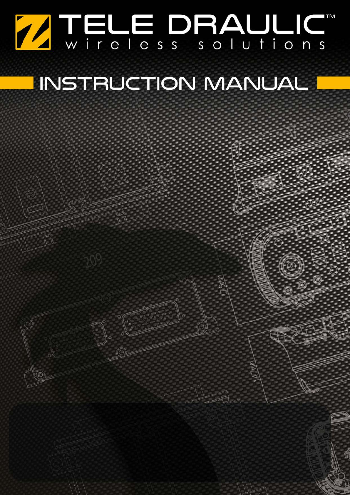
Installation
lOnlyauthorizedpersonnelmayinstalltheproduct.
lBeforeconnectingtheequipment,thepowersupplymustbeswitchedoff.
lAvoidinstallinginareasaffectedbystrongvibrations.
lThereceiverwithstandsnormalweatherconditionsbutshouldbeprotectedfromextremeconditions.The
receivershouldalsonotbesubjectedtomechanicalwaterpressurei.e.apressurewasherorsimilaradversecon-
ditions.
Avoidinstallingthereceiverinaplacewhereitwillbesubjectedtohighwaterflowsand/orheavyprecipitation.
lCableglandsandventplugsmustfacedownwardstopreventwaterfromseepingin.
MountthereceiverinsuchalocationthattheLEDscanbeeasilyseenandthebuttononthereceivercanbereached.
Makesuretoinstallpossibleaccessoriesinsideoronthereceiverbeforepermanentlyinstallingthereceiver.Apermanent
installationofthereceivermustincludefusesprotectingtheequipmentandcablesfromshortcircuit.
Onlycorrectinstallationmeetsthesafetylevelsfortheproduct.
102 mm (4.00 in)
Ø5 mm (0.20 in)
104 mm (4.10 in)
196 mm (7.70 in)
96 mm (3.80 in)
Ø6 mm (0.24 in)
Cableglandsforcustomizedsystemsaswellascablediameterwillbefoundinthetechnicaldocumentation.
9

Chapter 4: OPERATION
Maintenance
lUsethestopbuttontostartandswitchoffthetransmitterasoftenaspossible.
lIferrormessagesareshown,itisveryimportanttofindoutwhatcausedthem.
lIfthestopbuttonismechanicallydamaged,contactyourrepresentativeforserviceimmediately.
lAlwayscontactyourrepresentativeforserviceandmaintenanceworkontheproduct.
lAvoidregisteringtransmittersinreceiverswheretheyarenotbeingused.
lKeepthesafetyinstructionsforfuturereference.Alwaysdownloadtheconfigurationinstructionsfromourweb-
siteforthelatestavailableversion.
lMaintenanceworkmustbeperformedbyqualifiedpersonnelandaccordingtolawsandregulationsinthecoun-
trywerethesystemisbeingused.
CHAPTER 4│Installation instruction

Note: Alwaysholdthetransmitterwiththecontrolpaneltowardsyou.Theusermustbeabletoreadanytextonthe
controlpanelandunderstandthesymbolsonit.
Note: Transmittersnotinuseitmustbeswitchedoffandstoredinasecuredstoragespace.
Start-upprocedure
BeforeoperatingtheHydrasystemthefollowingproceduremustbefollowed.
1. Makesurethatallsafetymeasureshavebeenfollowed.
2. Makesurethetransmitterbatteryischarged.
3. Makesurethattheemergencystopbuttonispushedin.
4. TurnthekeyswitchtoONposition(horizontal).
5. Twistandreleasetheemergencystopbutton.
Initialstart-uplogodisplays.
BatteryLEDindicatorslights.
Note: Thedisplayshows"Sessionselection".Shouldthedisplayshowawarningonzeropositionforcontrol
switchorjoystick,releaseaffectedcontrolsifnecessarytoproceed.
6. Pressthetwostartbuttonssimultaneously.Keeppressedforasecond.
7. Releasebothbuttons.
Thetransmitterlogsintothereceiverinwhichitisregistered.
ThemiddleLEDflashesquicklywhilewaitingforthereceiverconfirmation.
WhensuccessfulthemiddleLEDlightswithafirmlight.
Note: Ifthepairedreceiverisnotdetectedwithin30s,loginprocesswillbecancelledandthetransmitterwill
automaticallyturnOFF.
8. Makesurethatthemachinefunctionscorrespondtothetransmitterfunctions.
9. Testemergencystop.
Warning: Donotusethesystemiftheemergencystopbuttondoesnotstoptheequipment.Doingsomaycauseser-
iousinjuryordeath.
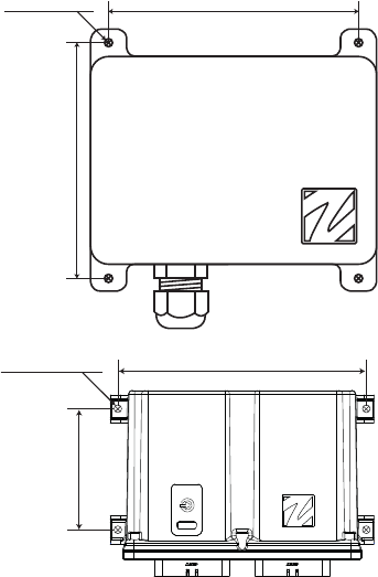
LEDsonreceiver
ThereceiverhasabuttonincludingsevenLEDsshowingthereceiverstatus.
LED1
LED2
LED3
LED4
LED5
2
3
1
1. LEDs1–5
2. DLEDs1–2
3. Capsensorbutton
LED Colour Off On Flashes Indicates
1 red x Radiolinkestablished.
x Notransmitterisregistered.
x Oneormoretransmittersisregistered,radiolinkisdown.
11

LED Colour Off On Flashes Indicates
2 yellow x Notransmitterisloggedin.
x Onetransmitterisloggedin.
3 yellow Notinuse.
4 orange Notinuse.
5 blue x Bluetoothnotactivatedbysettings.
Slow Bluetoothstandby.
Quick Bluetoothinparingmode.
x Bluetoothactivatedandcommunicating.
LED Colour Action Indicates
DLED1 Red CANopenerrorLED(CANinterface1)
Singleflash Warninglimitreached.
Flickering AutoBaud/LSS
Doubleflash ErrorControlEvent
Tripleflash SyncError
On BusOff
DLED1 Green CANopenrunLED(CANinterface1)
Flickering AutoBaud/LSS
Singleflash Stopped
Blinking Pre-operational
On Operational
DLED2 Red CANopenerrorLED(CANinterface2)
Singleflash Warninglimitreached.
Flickering AutoBaud/LSS
Doubleflash ErrorControlEvent
Tripleflash SyncError
On BusOff
DLED2 Green CANopenrunLED(CANinterface2)
Flickering AutoBaud/LSS
Singleflash Stopped
Blinking Pre-operational
On Operational
CHAPTER 4│Installation instruction
Chapter 5: REGULATORY
CEmarking
Thisproductisincompliancewiththeessentialrequirementsofdirective1995/5/ECoftheEuropeanParliamentandof
theCouncil.LatestversionoftheECDeclarationofConformitycanbedownloadedfromtheTeleRadioABwebsite.
FCCstatement
Thisdevicecomplieswithpart15oftheFCCRules.Operationissubjecttothefollowingtwoconditions:(1)Thisdevice
maynotcauseharmfulinterference,and(2)thisdevicemustacceptanyinterferencereceived,includinginterferencethat
maycauseundesiredoperation.
Changesormodificationsnotexpresslyapprovedbythepartyresponsibleforcompliancecouldvoidtheuser’sauthority
tooperatetheequipment.
ThisequipmenthasbeentestedandfoundtocomplywiththelimitsforaClassBdigitaldevice,pursuanttopart15ofthe
FCCRules.Theselimitsaredesignedtoprovidereasonableprotectionagainstharmfulinterferenceinaresidentialinstall-
ation.Thisequipmentgeneratesusesandcanradiateradiofrequencyenergyand,ifnotinstalledandusedinaccordance
withtheinstructions,maycauseharmfulinterferencetoradiocommunications.Howeverthereisnoguaranteethatinter-
ferencewillnotoccurinaparticularinstallation.Ifthisequipmentdoescauseharmfulinterferencetoradioortelevision
reception,whichcanbedeterminedbyturningtheequipmentoffandon,theuserisencouragedtotrytocorrecttheinter-
ferencebyoneormoreofthefollowingmeasures:
–Reorientorrelocatethereceivingantenna.
–Increasetheseparationbetweentheequipmentandreceiver.
–Connecttheequipmentintoanoutletonacircuitdifferentfromthattowhichthereceiverisconnected.
–Consultthedealeroranexperiencedradio/TVtechnicianforhelp.
TosatisfyFCCRFexposurerequirements,aseparationdistanceof20cmormoreshouldbemaintainedbetweenthe
antennaofthisdeviceandpersonsduringdeviceoperation.
Toensurecompliance,operationsatcloserthanthisdistanceisnotrecommended.
TheradiomoduleinthisproductislabelledwithitsownFCCIDandICnumber.TheFCCIDandICisnotvisiblewhenthe
radiomoduleisinstalledinsideanotherdevice.Therefore,theoutsideofthedeviceintowhichthemoduleisinstalledmust
alsodisplayalabelreferringtotheradiomodule.Thefinalenddevicemustbelabelledinavisibleareawiththefollowing:
“ContainsFCCID:ONFC1602A”
“ContainsIC:4807A-C1602A”
13

ICstatement
ThisproductcomplieswithIndustryCanada'slicence-exemptRSSs.Operationissubjecttothefollowingtwoconditions:
(1)Thisdevicemaynotcauseinterference;and
(2)Thisdevicemustacceptanyinterference,includinginterferencethatmaycauseundesiredoperationofdevice.
LeprésentappareilestconformeauxCNRd'IndustrieCanadaapplicablesauxappareilsradioexemptsdelicence.
L'exploitationestautoriséeauxdeuxconditionssuivantes:(1)l'appareilnedoitpasproduiredebrouillage,et(2)
l'utilisateurdel'appareildoitacceptertoutbrouillageradioélectriquesubi,mêmesilebrouillageestsusceptibled'encom-
promettrelefonctionnement.
Thisradiotransmitter(identifythedevicebycertificationnumber,ormodelnumberifCategoryII)hasbeenapprovedby
IndustryCanadatooperatewiththeantennatypeslistedbelowwiththemaximumpermissiblegainandrequiredantenna
impedanceforeachantennatypeindicated.Antennatypesnotincludedinthislist,havingagaingreaterthanthemax-
imumgainindicatedforthattype,arestrictlyprohibitedforusewiththisdevice.
Gainofantenna:3.0dBimax.
Typeofantenna:50ohm,Omni-directional
Leprésentémetteurradio(identifierledispositifparsonnumérodecertificationousonnumérodemodèles'ilfaitpartie
dumatérieldecatégorieI)aétéapprouvéparIndustrieCanadapourfonctionneraveclestypesd'antenneénumérésce-
dessouserayantungainadmissiblemaximalerl'impédancerequisepourchaquetyped'antenne.Lestypesd'antenne
noninclusdanscetteliste,oudontlegainestsupérieuraugainmaximalindiqué,sontstrictementinterditspour
l'exploitationdel'émetteur.
Gaind'antenne:3.0dBimaximal
Typed'antenne:50ohm,Omni-directionnel
TosatisfyICRFexposurerequirements,aseparationdistanceof20cmormoreshouldbemaintainedbetweenthe
antennaofthisdeviceandpersonsduringdeviceoperation.Toensurecompliance,operationsatcloserthanthisdistance
isnotrecommended.
Lesantennesinstalléesdoiventêtresituéesdefaconàcequelapopulationnepuisseyêtreexposéeàunedistancede
moinde20cm.Installerlesantennesdefaconàcequelepersonnelnepuisseapprocherà20cmoumoinsdelaposition
centraledel'antenne.LaFCCdeséltats-unisstipulequecetappareildoitêtreentouttempséloignéd'aumoins20cmper-
sonnespendantsonfunctionnement.
TheradiomoduleinthisproductislabelledwithitsownFCCIDandICnumber.TheFCCIDandICisnotvisiblewhenthe
radiomoduleisinstalledinsideanotherdevice.Therefore,theoutsideofthedeviceintowhichthemoduleisinstalledmust
alsodisplayalabelreferringtotheradiomodule.Thefinalenddevicemustbelabelledinavisibleareawiththefollowing:
“ContainsFCCID:ONFC1602A”
“ContainsIC:4807A-C1602A”
CHAPTER 5│Installation instruction
FCC/IClabelplacement
TheFCC/IClabelisplacedontheradiomoduleTheradiomoduleisfittedinsidethereceiver.
Productlabelonthereceiver
Youwillfindtheproductlabelontheoutsideoftheenclosureofthereceiver.
Theradiomodule
EachradiomoduleisspecificallydesignedtomatchaTeleDraulicproductintermsofphysicaldimensions,connection
points,voltagelevels,signalinterfaceetc.TousetheradiomodulesinnonTeleDraulicproductsisnotpermitted.The
radiomodulesaredesignedtointerfacedirectlytothemainboardofthereceiver/transmitterunit.Theyarepowersup-
pliedbythemainboardandtheradiocircuitoperatesstrictlyaccordingtoinstructionsfromamicroprocessoronthemain
board.Theradiocircuitconfigurationisstoredinaflashmemoryontheradiomodule.Areceiver/transmitterunitwitha
defective/noradiomodulewillgiveanerrormessageimmediatelyafterpowerup,anditwillnotbepossibletostartaradio
session.
15