Tele Radio 860TX-12-05 REMOTE CONTROL TRANSMITTER User Manual IM 860 010 A2 indb
Tele Radio AB REMOTE CONTROL TRANSMITTER IM 860 010 A2 indb
UserManual.wiki
>
Tele Radio
>
860TX 12 05 User Manual
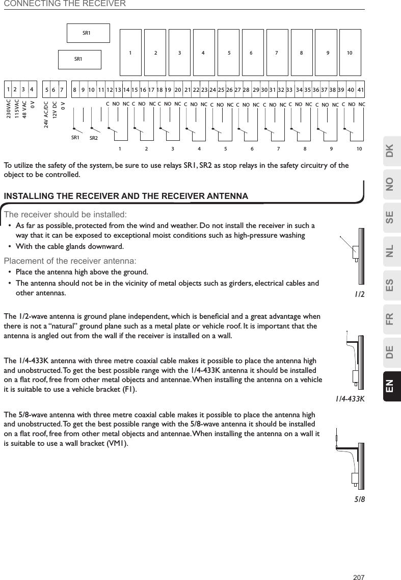
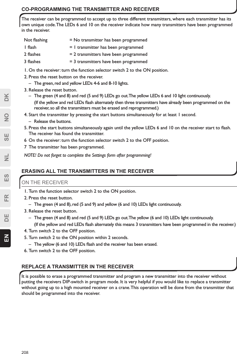
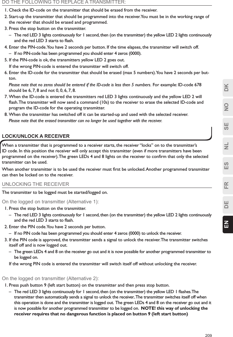
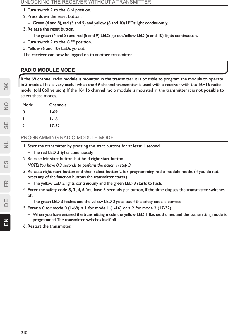
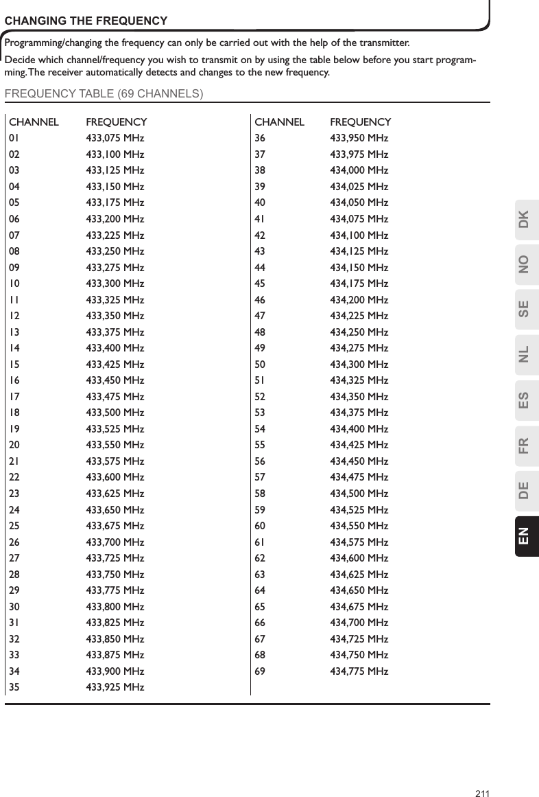
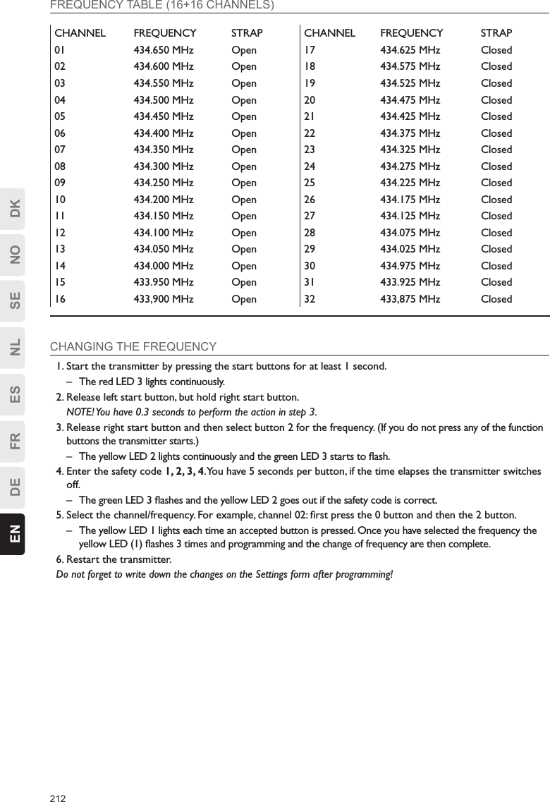
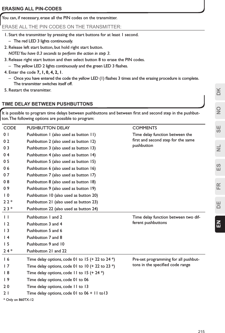
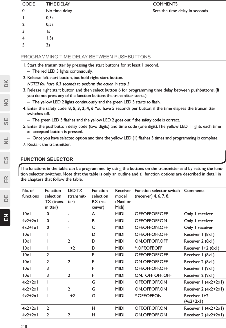
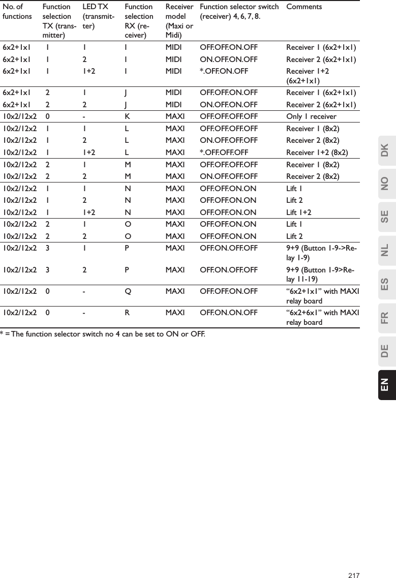
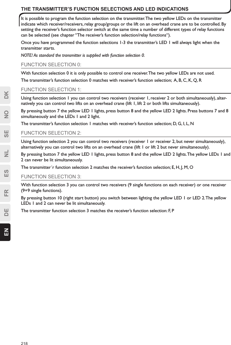
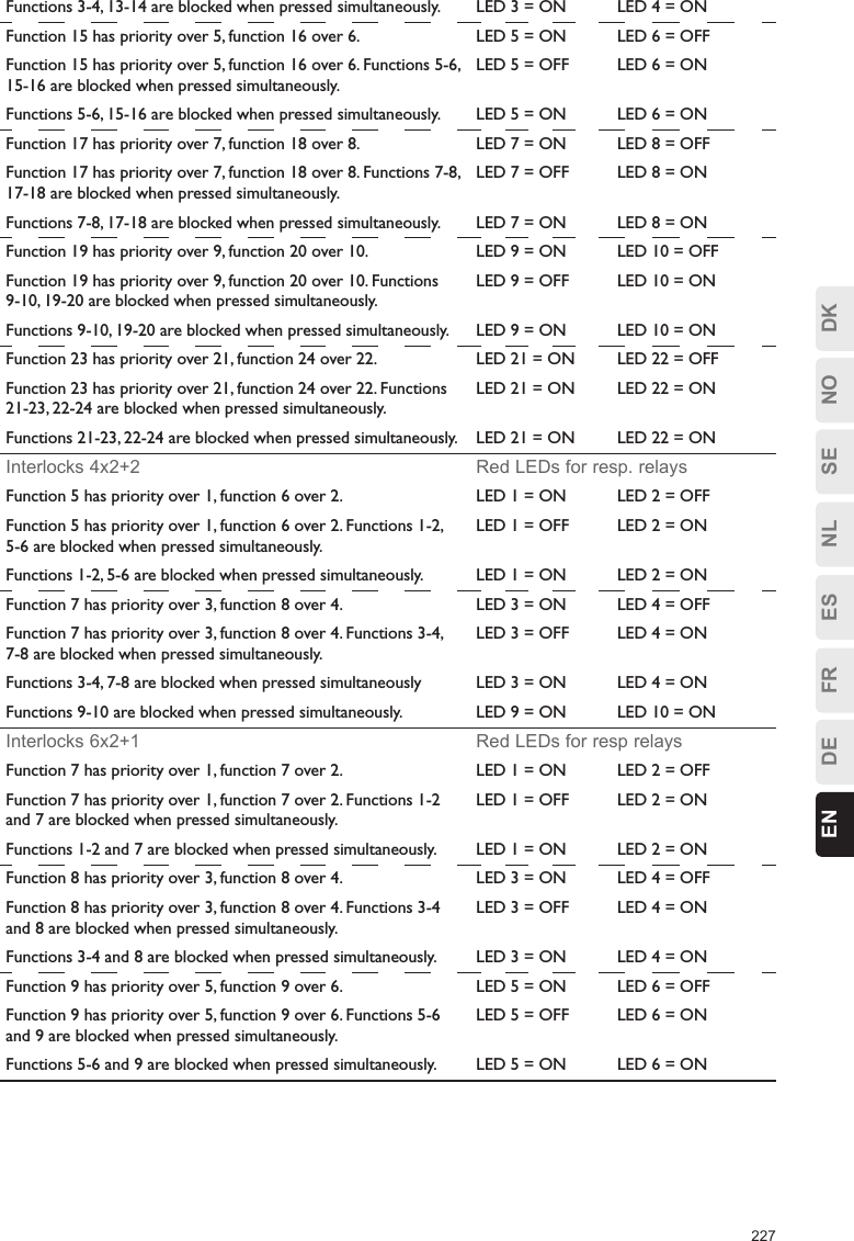
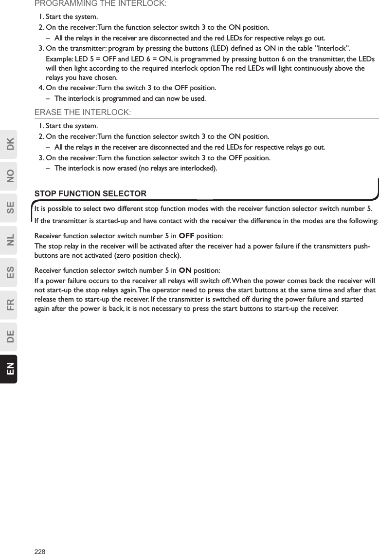
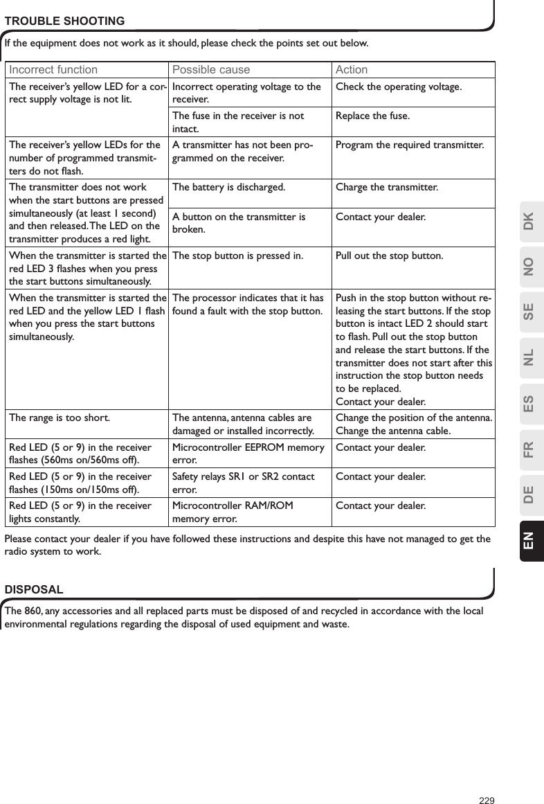
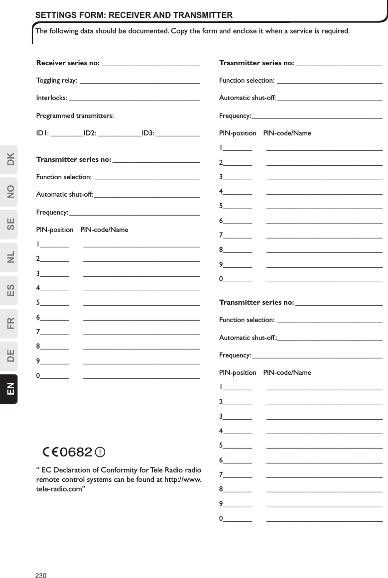
USERS MANUAL
Navigation menu
Upload a User Manual
Namespaces
Wiki Guide
HTML
PDF
Info
Views
User Manual
Discussion / Help
Navigation