Tele Radio C0911A Transmitter User Manual Revised
Tele Radio AB Transmitter Users Manual Revised
Users Manual Revised
Tele Radio Panther
SAFETY INSTRUCTIONS
IM-PN-TX001-A02-EN
ARTICLE CODE: PN-R8-1, PN-R8-2, PN-R8-6, PN-T7-3, PN-T7-4, PN-T7-5.
LANGUAGE: ENGLISH (ORIGINAL)

Thank you for puchasing a Tele Radio product
PN-R8-1, PN-R8-2, PN-R8-6, PN-T7-3, PN-T7-4, PN-T7-5
INSTRUCTIONS ARE AVAILABLE FOR DOWNLOAD AT: www.tele-radio.com
READ ALL INSTRUCTIONS CAREFULLY BEFORE MOUNTING, INSTALLING AND
CONFIGURATING THE PRODUCT.
These instructions are published by Tele Radio AB without any guarantee. These
instructions are solely directed towards qualied installers. The instructions may be
removed or revised by Tele radio AB at any time and without any further notice.
Corrections and additions will be added to the updated versions of the instructions.
The instructions that contain information on the installation and conguration of the
remote radio control unit on the machine are not intended to be passed on to the end
user. Only such information may be passed on to the end user, that is needed to operate
the machine correctly by radio remote control.
Tele Radio AB products are covered by a guarantee against material, construction or
manufacturing faults. During the guarantee period, Tele Radio AB may replace the product
or faulty parts with new. Work under guarantee must be carried out by Tele Radio AB
or by an authorized service centre specied by Tele Radio AB. Make sure that repairs and
maintenance are only carried out by qualied personnel. Use only spare parts from Tele
Radio AB. Contact your Tele Radio representative if you need service or support. The EC
declaration of conformity can be downloaded from our website.
©Tele Radio AB, 2010
TELE RADIO AB
Datavägen 21, SE-436 32 Askim. Sweden
Tel: +46 (0)31-748 54 60
Fax: +46 (0)31-68 54 64
www.tele-radio.com.
info@tele-radio.com
The helpdesk group can help you with questions
regarding service and technical support.
helpdesk@tele-radio.com

5

6Contents
CONTENTS
TECHNICAL DATA RECEIVER
Receiver (base board) 7
Receiver (base + relay expansion board) 8
Receiver (base + high voltage expansion board) 9
Current consumption 10
Receiver data 11
TECHNICAL DATA TRANSMITTER
Transmitter 10
Batteries 13
Change the batteries 13
SETTINGS
Start the transmitter 14
Turn the transmitter off 14
Register the transmitter in the receiver 15
Erase all transmitters from the receiver 15
LED indications 17
Placement of labels with IC and FCC information 19
FCC statement 21
Guarantee, service, repairs and maintenance 21
Battery precautions 22
Disposal of batteries 23
Disposal of electronics 23
6
18
19
20
LED7 LED8
LED6
LED9
LED10
F
S
Relay 5 Relay 1 Relay 3Relay 2 Relay 4
5 1 2 3 4
+ -
12-24 V DC
CO NO NC
WR/5
CO NO NC
1 (on/off)
CO NO NC
2
CO NO NC
3 (kill)
CO NO NC
4 (Buzzer)
1
2
3
4
5
6
7
8
9
10
11
12
13
14
15
16
17
LEDs
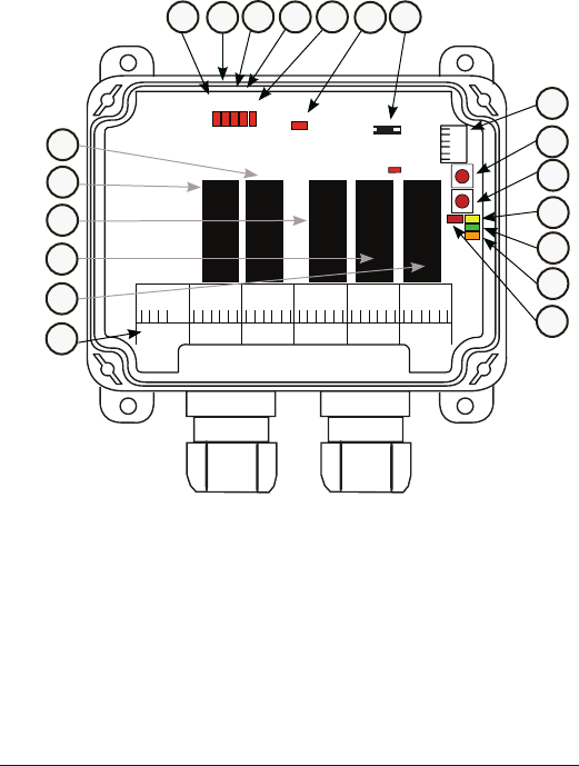
TECHNICAL DATA RECEIVER
R8-1 (BASE BOARD)
1. Relay 1- on/off relay
2. Relay 5- working relay
3. Relay 2
4. Relay 3- kill relay
5. Relay 4- buzzer relay
6. Power supply connection
6-30 V DC
7. Relay LED 5
8. Relay LED 1
9. Relay LED 2
10. Relay LED 3
11. Relay LED 4
12. Power supply LED 6
13. Trabus programming connector
14. Terminal block for RS232
15. Function button (Cancel)
16. Select button (OK)
17. LED 8
18. Base board communication
LED 9
19. LED 10
20. LED 7
1
2
3
4
5
6
78910 11 13
12
14
15
16
17
18
19
20
7
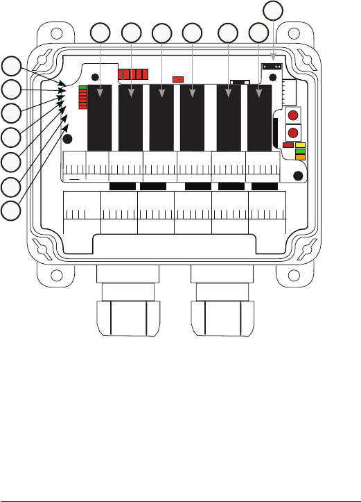
R8-6 (BASE + RELAY EXPANSION BOARD)
21. Expansion board
communication LED 11
22. Relay LED 6
23. Relay LED 7
24. Relay LED 8
25. Relay LED 9
26. Relay LED 10
27. Relay LED 11
28. Relay 6
29. Relay 7
30. Relay 8
31. Relay 9
32. Relay 10
33. Relay 11
34. Trabus programming connector
18
19
20
LED7 LED8
LED6
LED9
LED10
F
S
Relay 5 Relay 1 Relay 3Relay 2 Relay 4
5 1 2 3 4
+ -
12-24 V DC
CO NO NC
WR/5
CO NO NC
1
(on/off)
CO NO NC
2
CO NO NC
3
(kill)
CO NO NC
4
(Buzzer)
1
2
3
4
5
6
7
8
9
10
11
12
13
14
15
16
17
LEDs
Relay 6 Relay 7 Relay 8 Relay 10
Relay 9 Relay 11
LED
LED6
LED7
LED8
LED9
LED10
LED11
21
22
23
24
25
26
27
28
29
30
31
32
33
34
35
36
37
38
39
CO NO NC
CO CO NO NC CO NO NC CO NO NC CO NO NC CO NO NC
678910 11
21
28 29 30 31 32 33
34
22
23
24
25
26
27
8
18
19
20
LED7 LED8
LED6
LED9
LED10
F
S
Relay 5 Relay 1 Relay 3Relay 2 Relay 4
5 1 2 3 4
+
-
12-24 V DC
CO NO NC
WR/5
CO NO NC
1
(on/off)
CO NO NC
2
CO NO NC
3
(kill)
CO NO NC
4
(Buzzer)
1
2
3
4
5
6
7
8
9
10
11
12
13
14
15
16
17
LEDs
21
22
23
24
COMMON
24-110 V AC
230 V AC
LED
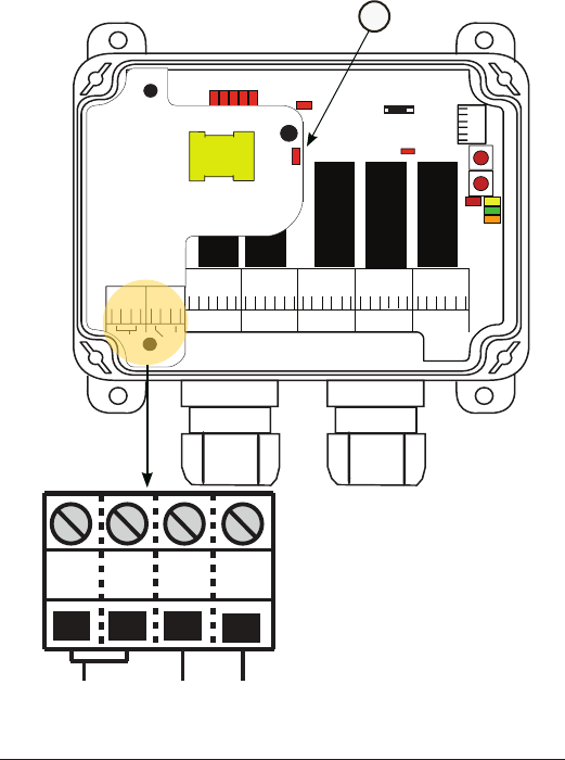
R8-2 (BASE + HIGH VOLTAGE EXPANSION BOARD)
Recommended cable for RS232 is a twisted or shielded cable.
22
21 23 24
COMMON 24-110 V AC 230 V AC
35
35. Power supply LED 12

9
Current consumption
RX MODEL SUPPLY VOLTAGE MAX. CURRENT CONSUMPTION
R8-1 12-24 V DC <200 mA.
R8-2 24-230 V AC <200 mA.
R8-6 12-24 V DC <300 mA.
Technical data
FUNCTIONAL RELAYS: 5/ 11 potential free* functional relays
makes/ breaks 8A ACI
NUMBER OF CHANNELS: 16
SIZE: 120 x 116 x 50 mm./
4.7” x 4.6” x 2”
WEIGHT: 400-500 grams/ 14-18 oz.
IP CLASS: IP66
10 Technical data transmitter
17 18 19
3
2
1
1st step
2nd step
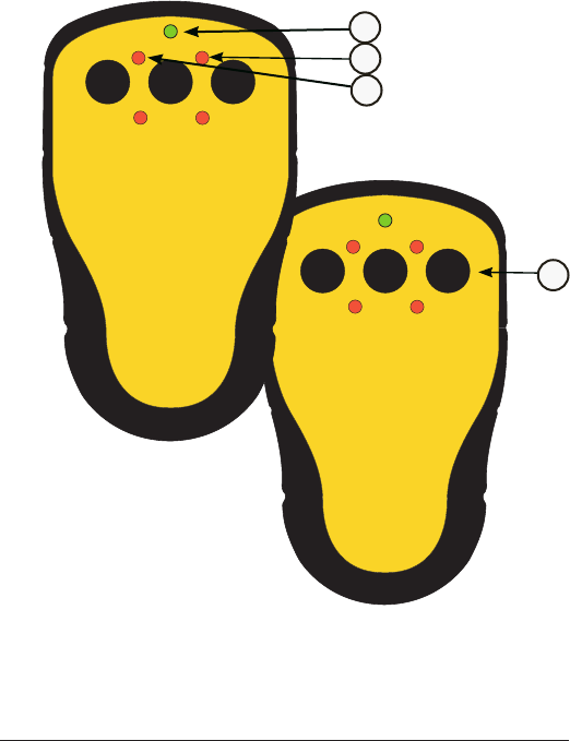
TECHNICAL DATA TRANSMITTER
3-BUTTONS TRANSMITTER T5
1. Top LED (red/green)
2. LED 2 (red)
3. LED 1 (red)
4. 2-step buttons 1-3
NOTE! The right transmitter shows the
button positions for the second step on
the 3-button transmitter.
1
2
3
4
Frequency: 2405-2480 MHz.
11
Technical data transmitter
222120
17 18 19
6
5
4
3
2
1
1st step
2nd step
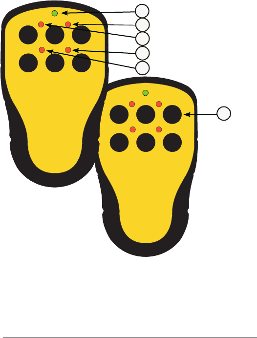
6-BUTTONS TRANSMITTER T4
1. Top LED (red/green)
2. LED 2 (red)
3. LED 1 (red)
4. LED 4 (red)
5. LED 3 (red)
6. 2-step buttons 1-6
NOTE! The right transmitter shows the
button positions for the second step on the
6-button transmitter.
1
2
3
4
5
6
Frequency: 2405-2480 MHz.
12 Technical data transmitter
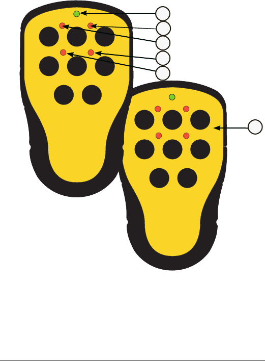
8-BUTTONS TRANSMITTER T3
1. Top LED (red/green)
2. LED 2 (red)
3. LED 1 (red)
4. LED 4 (red)
5. LED 3 (red)
6. 2-step buttons 1-8
NOTE! The right transmitter shows the
button positions for the second step on
the 8-button transmitter.
2423
222120
17 18 19
78
6
5
4
3
2
1
1st step
2nd step
1
2
3
4
5
6
Frequency: 2405-2480 MHz.
13
Technical data transmitter
BATTERIES
BATTERY TYPE: 3 x 1.5 V
AAA alkaline
OPERATING TIME: Approx. 15 h. with continuous usage
WARNING! Do not recharge! Attempts to recharge may cause rupture,
or the leaking of hazardous liquids which will corrode the equipment.
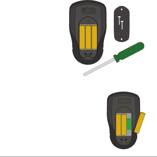
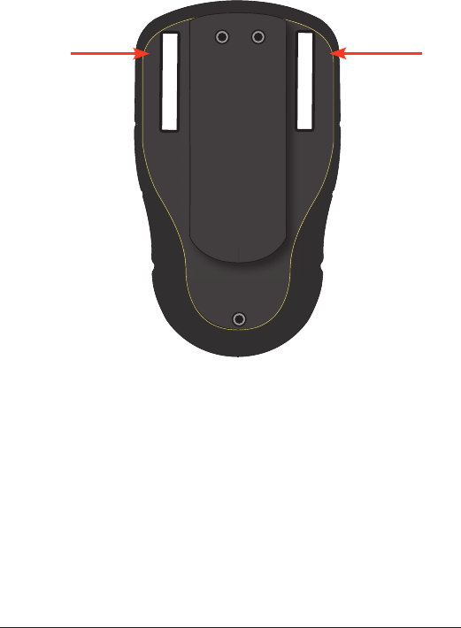
CHANGE THE BATTERIES
1. Remove the clip (2 screws).
2. Remove the battery cover (2
screws).
3. Remove the batteries,
starting with the one in the
middle.
4. Put the new batteries (3 x
1.5V AAA batteries) in, start-
ing with the battery to the
left or to the right.
5. Put back the battery cover (2
screws).
PROGRAM THE TRANSMITTER
1. Remove the clip (2 screws).
2. Remove the battery cover (2 screws).
3. Remove the right battery. The program-
ming connector is placed behind the
battery.

14 Settings
SETTINGS
• discontinuous radiotransmission
• no on/off function
The system will start transmitting as soon as the batteries are inserted
and a transmitter button is pressed. Radio transmission will end as soon
as no transmitter button is being pressed.
DEFAULT STATE
START THE TRANSMITTER
TURN THE TRANSMITTER OFF
1. Start the transmitter by pressing any transmitter button.
1. The transmitter turns off when no transmitter button is pressed.

15
Settings
1. Press the receiver Function button and the Select button at the
same time until red LED 1-5 go out.
NOTE! If red LED 7 ashes slowly, one or several transmitters are still
registered in the receiver.
REGISTER THE TRANSMITTER IN THE RECEIVER
ERASE ALL TRANSMITTERS FROM THE RECEIVER
1. Press the receiver Function button until red LED 7 lights up.
2. Press the receiver Select button until LEDs 1-5 light.
3. Press any transmitter button, e.g. button 1 until LEDs 1-10 ash 3
times before going out.

16 Settings
All buttons (step 1 and/ or 2) as well as all relays can be re-mapped using
the PC program Settings manager. At delivery, the default relay setting is:
R8-1:
Transmitter button 1 (1st + 2nd step) activates relay 1
Transmitter button 2 (1st + 2nd step) activates relay 2
Transmitter button 3 (1st + 2nd step) activates relay 3
Transmitter button 4 (1st + 2nd step) activates relay 4
Transmitter button 5 (1st + 2nd step) activates relay 5
R8-6 with a 6 relay expansion board connected:
Transmitter button 6 (1st + 2nd step) activates relay 6
Transmitter button 7 (1st + 2nd step) activates relay 7
Transmitter button 8 (1st + 2nd step) activates relay 8
RELAY SETTINGS
17
LED INDICATIONS
LED INDICATIONS DURING START UP
1. All receiver relay-LEDs lit up for 0.5 sec.
2. Indications for settings are shown for 2 sec. Contact your
representative if you have problems starting the system.
LED INDICATIONS IN PROGRAMMING MODE
LED 7 red ON
LED 8 yellow ON
LED 9 green ON
LED 10 orange ON
LED INDICATIONS DURING OPERATION
LED 7 red OFF No transmitter registered
ashes
(on 500 ms./ off 1.5 s.)
Transmitter logged in.
ashes
(on 1 s./ off 1 s.)
At least one
transmitter registered.
No radio transmission.
ON Valid radio packages from
transmitter received.

18
ERROR LED INDICATIONS
LED 7
(red)
+ LED 8
(yellow)
ON The receiver can not read the start-up
information. Contact your
representative.
LED 7
(red)
ON Radio module setup failed. Contact
your representative.
LED 8 ON A radio package not coming from a
Panther transmitter is received.
LED 8 + LED 9 ON A radio package is received, but is not
accepted. Contact your representative.
LED 8 + LED 10 ON A radio package is received from a
transmitter that is not registered.
Register the transmitter, or switch to
another frequency.
LED 9 ON A radio package is received, but the
radio signal strength is too weak.
Contact your representative for more
information.
LED 10 ON A radio package is received, but is not
accepted. Contact your representative.
19
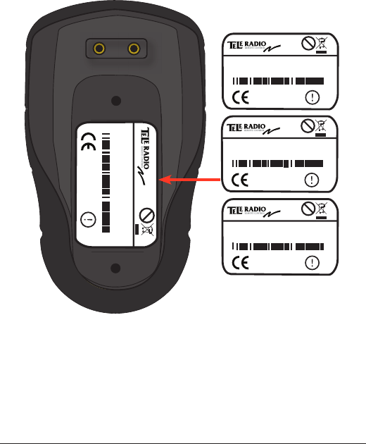
PLACEMENT OF LABELS WITH IC AND FCC
INFORMATION
1. Product label
The product label is placed under the clip on the battery lid. Remove the
clip (2 screws).
1.
Pb
Model: T00007-03
Freq.: 2405-2480MHz
Sn.:XXXXXX
www.tele-radio.com
2150
Pb
Model: T00007-04
Freq.: 2405-2480MHz
Sn.:XXXXXX
www.tele-radio.com
2150
Pb
Model: T00007-05
Freq.: 2405-2480MHz
Sn.:XXXXXX
www.tele-radio.com
2150
Pb
Model: T00007-05
Freq.: 2405-2480MHz
Sn.:XXXXXX
www.tele-radio.com
2150
20
The IC label is placed on the left side of the battery clip. The FCC ID label
is placed on the right side of the battery clip (see picture).
The mobile device is also designed to meet the requirements for
exposure to radio waves established by the Federal Communications
Commission (USA). These requirements set a SAR limit of 1.6 W/kg
averaged over one gram of tissue. The highest SAR value reported under
this standard during product certication for use when properly worn on
the body is 0.087 W/kg.
2.
2. IC and FCC ID label
FCC ID: ONFC0911A
IC: 4807A-C0911A

21
FCC STATEMENTS
THIS DEVICE COMPLIES WITH PART 15 OF THE FCC RULES.
OPERATION IS SUBJECT TO THE FOLLOWING TWO CONDITIONS:
1. THIS DEVICE MAY NOT CAUSE HARMFUL INTERFERENCE
2. THIS DEVICE MUST ACCEPT ANY INTERFERENCE THAT MAY
CAUSE UNDESIRED OPERATION. NOTE: THE MANUFACTURER
IS NOT RESPONSIBLE FOR ANY RADIO OR TV INTERFERENCE
CAUSED BY UNAUTHORIZED MODIFICATIONS TO THIS EQUIP-
MENT. SUCH MODIFICATIONS COULD VOID THE USER´S AUTHOR-
ITY TO OPERATE THE EQUIPMENT.
THIS EQUIPMENT COMPLIES WITH FCC RADIATION EXPOSURE
LIMITS SET FORTH FOR AN UNCONTROLLED ENVIRONMENT.
END USER MUST FOLLOW THE SPECIFIC OPERATING
INSTRUCTIONS FOR SATISFYING RF EXPOSURE COMPLIANCE. THIS
TRANSMITTER MUST NOT BE CO-LOCATED OR OPERATING IN
CONJUNCTION WITH ANY OTHER ANTENNA OR TRANSMITTER.
GUARANTEE, SERVICE, REPAIRS AND
MAINTENANCE
The Tele Radio products are covered by a guarantee against material,
construction and manufacturing faults. During the guarantee period, Tele
Radio may replace the product or faulty parts. Work under guarantee
must be carried out by Tele Radio or by an authorized service centre
specied by Tele Radio. This is not covered by the guarantee: Faults
resulting from normal wear and tear. Parts of a consumable nature.
Products that have been subject to unauthorized modications. Faults
resulting from incorrect installation and use. Damp and water damage.
Repairs and maintenance must be carried out by qualied personnel. Use
spare parts from Tele Radio only. Contact your representant or HelpDesk
if you require service or other assistance. Keep the product in a dry, clean
place. Keep contacts and antennas clean. Wipe off dust using a slightly
damp, clean cloth. Never use cleaning solutions or high-pressure water.

20 Battery Precautions
BATTERY PRECAUTIONS
Observe the following warnings. As batteries contains
ammable substances such as lithium or other organic
solvents, they may cause heating, rupture or ignition.
• Risk of explosion if battery is replaced with a battery of an incorrect
type.
• Do not short circuit, disassemble, deform or heat batteries.
• Never try to charge a visibly damaged or frozen battery.
• Do not charge rechargeable batteries with a higher voltage than
specied.
• Keep batteries out of reach of small children. Should a child swallow a
battery, consult a physician immediately.
• Avoid direct soldering to batteries.
• When discarding batteries, insulate the + and - terminals of batteries
with insulating/ masking tape. Do not put multiple batteries in the same
plastic bag.
• When improperly disposed, lithium batteries may short circuit, causing
them to become hot, burst or ignite.
• Store in a cool location. Keep batteries away from direct sunlight, high
temperature, and high humidity.
• Do not throw batteries into re.

21
Disposal Of Electronics
DISPOSAL OF BATTERIES
An alkaline battery does not contain mercury, cadmium or lead, and is
better for the environment than older types of batteries. Alkaline
batteries should be disposed through local recycling stations/waste dumps.
Contact your local government’s recycling or solid waste
department for more information on proper recycling of
alkaline batteries in your region.
DISPOSAL OF ELECTRONICS
Improperly disposed electronics may harm public health
and the environment. Batteries and electronic waste may
contain toxic heavy metals. If thrown away in the trash, the toxic
compounds can leach into soil and water, pollute lakes and streams,
making them unt for drinking, swimming, shing, and wildlife. Contact
your local government’s recycling or solid waste department for more
information on proper disposal of electronics in your region.
TELE RADIO SVERIGE
Sweden
Tel. +46 (0)31-724 98 00
e-mail: sverige@tele-radio.com
TELE RADIO GmbH
Germany
Tel. +49 (0)94 51-944 8 550
e-mail: deutschland@tele-radio.com
TELE RADIO ASIA
China
Tel. +86-(0)592-3111168
e-mail: china@tele-radio.com
TELE RADIO TURKEY
Turkey
Tel. +90 216 574 22 94
e-mail: turkiye@tele-radio.com
TELE RADIO LTD
England
Tel. +44 (0) 1625 509125
e-mail: england@tele-radio.com
TELE RADIO LLC
North America & Latin America
Tel. +1 (305) 459 0763
e-mail: america@tele-radio.com
TELE RADIO BV
Benelux
Tel. +31-(0)70-419 41 20
e-mail: benelux@tele-radio.com
TELE RADIO AS
Norway
Tel. +47-6933 4900
e-mail: norge@tele-radio.com
TELE RADIO AB
Sweden, Main office
Tel. +46 (0)31-748 54 60
e-mail: info@tele-radio.com
www.tele-radio.com