Tele Radio C1013A TRANSMITTER User Manual ONFC1013A 4807A C1013A
Tele Radio AB TRANSMITTER ONFC1013A 4807A C1013A
ONFC1013A & 4807A-C1013A User manual
Tele Radio 860 Lion
INSTALLATION INSTRUCTIONS
T00003-20
FCC-IM-860-TX016-A01
ARTICLE CODE: RX1-A , RX2-A,
RX3-A, RX4-A, T00003-20
LANGUAGE: ENGLISH (ORIGINAL)

Thank you for purchasing a Tele Radio product
RX1-A, RX2-A, RX3-A, RX4-A, T00003-20
DOWNLOAD INSTALLATION INSTRUCTIONS FROM: www.tele-radio.com
READ ALL INSTRUCTIONS CAREFULLY BEFORE MOUNTING, INSTALLING AND
CONFIGURATING THE PRODUCT.
These instructions are published by Tele Radio AB without any guarantee. These
instructions are solely directed towards qualied installers. The instructions may be
removed or revised by Tele radio AB at any time and without any further notice.
Corrections and additions will be added to the updated versions of the instructions.
The instructions that contain information on the installation and conguration of the
remote radio control unit on the machine are not intended to be passed on to the end
user. Only such information may be passed on to the end user, that is needed to operate
the machine correctly by radio remote control. A separate End user instruction is
available for download from: www.tele-radio.com
Tele Radio AB products are covered by a guarantee against material, construction or
manufacturing faults. During the guarantee period, Tele Radio AB may replace the product
or faulty parts with new. Work under guarantee must be carried out by Tele Radio AB
or by an authorized service centre specied by Tele Radio AB. Make sure that repairs and
maintenance are only carried out by qualied personnel. Use only spare parts from Tele
Radio AB. Contact your Tele Radio representative if you want to make a complaint about
a product or require other service.
©Tele Radio AB, 2010
TELE RADIO AB
Datavägen 21, SE-436 32 Askim. Sweden
Tel: +46 (0)31-748 54 60
Fax: +46 (0)31-68 54 64
www.tele-radio.com.
info@tele-radio.com
The helpdesk group can help you with questions
regarding service and technical support.
helpdesk@tele-radio.com
CONTENTS
TECHNICAL DATA RECEIVER 7
CURRENT CONSUMPTION 9
CONNECT AND INSTALL THE RECEIVER 10
TECHNICAL DATA TRANSMITTER 11
CHARGE THE BATTERY 12
START THE TRANSMITTER 13
TURN THE TRANSMITTER OFF 13
REGISTER THE TRANSMITTER IN THE RECEIVER 13
ERASE THE TRANSMITTER FROM THE RECEIVER 14
FREQUENCY SETTINGS 14
PLACEMENT OF LABELS WITH IC AND FCC INFORMATION 16
FCC STATEMENTS 17
RADIO TRANSMISSION 18
GUARANTEE, SERVICE, REPAIRS AND MAINTENANCE 17
BATTERIES, ELECTRONICS, DISPOSAL AND RECYCLING 18
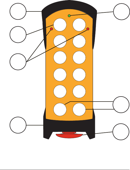
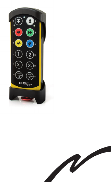
6Technical Data Transmitter
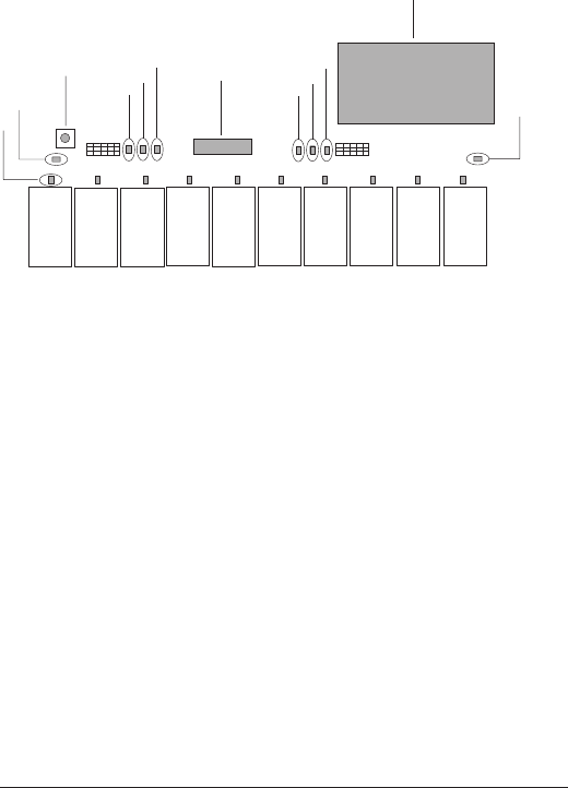
TECHNICAL DATA TRANSMITTER
1. removable rubber cover
2. 2-step buttons 1-12
3. red/green top LED
4. red LEDs 1 + 2
5. stop button
6. buttons 11+12: start buttons
12
109
78
6
5
4
3
21
11
13
5
6
4
2
1
7
Technical Data Transmitter
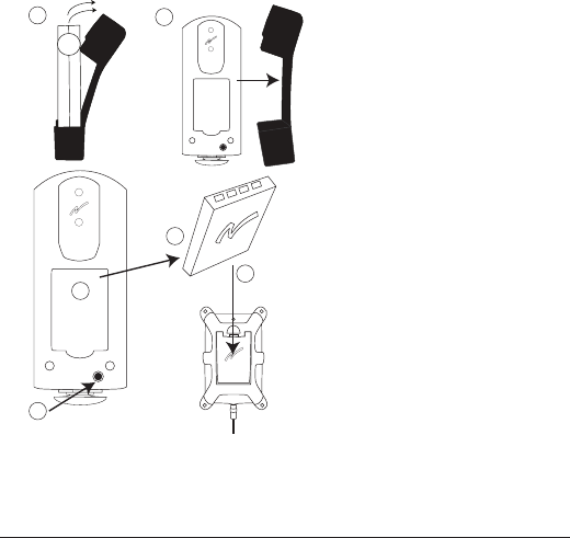
CHARGE THE BATTERY
2
1a 1b
3
4
5
(1a+1b) Remove the rubber cover.
(2)The battery is placed in the back of the transmitter.
(3) Remove the battery to charge in the battery charger (4).
(5) or charge the battery directly in the transmitter
TECHNICAL DATA
DEGREE OF PROTECTION: IP 65
OPERATING FREQUENCY: 433.075-434.775 MHz
CHANNELS: 69
SIZE: 200 x 70 x 35 mm./ 7.9 x 2.8 x 1.4 in.
WEIGHT: 400 g./ 14.1 oz.
BATTERY: 1 external, rechargeable battery (li-ion)
8Technical Data Receiver
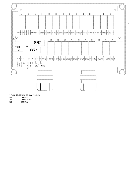
TECHNICAL DATA RECEIVER
* Fuse S1, S2 and S3 ceramic slow
S1: 200 mA.
S2: 300-315 mA.
S3: 500 mA.
9
Technical Data Receiver
1. Red LED 1
2. Yellow LED 2
3. Reset button
4. Green LED 4
5. Red LED 5
6. Yellow LED 6
7. Function selector switch
8. Green LED 8
9. Red LED 9
10. Yellow LED 10
11. Radio module
12. Green LED 12
4
5
6
8
9
10
7
2
3
12
11
1
RELAY OUTPUTS: Midi: 10+2 for stop function
Maxi: 24+2 for stop function
STOP RELAY: Potential free*, makes 8A AC1
FUNCTION RELAY: Potential free*, breaks/makes 16A AC1
RADIO: PLL synthesizer.
CHANNELS: 69 (433.075-434.775 MHz.)
SIZE: 250 x 175 x 75 mm.
9.8 x 6.9 x 3 in.
WEIGHT: 1.900 g./4.19 lb.
ENCLOSURE CLASS: IP 65
ANTENNA CONNECTOR: BNC
*potential-free means that you need to supply voltage to get power out of a relay.
10 Technical Data Receiver
RECEIVER LEDS
LED 2 lights yellow when the receiver has the correct supply voltage.
LEDs 6 + 10 ash in yellow 1, 2 or 3 times, depending on how many
transmitters that are registered in the receiver.
LED 12 lights green when the receiver receives radio signals (433.075 –
434.775 MHz).
LEDs 4 + 8 light green when a transmitter is logged in to the receiver.
LEDs 5 + 9 light red to indicate a fault on the receiver. Contact your
representative.
Each relay has a LED that lights red when the relay is activated.
CURRENT CONSUMPTION
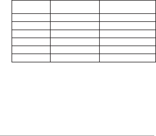
SUPPLY VOLTAGE POWER
CONSUMPTION:MIN.
POWER
CONSUMPTION: MAX.
12V DC 150 mA 1 A
24V DC 60 mA 600 mA
24V AC 80 mA 800 mA
48V AC 100 mA 400 mA
115V AC 70 mA 200 mA
230V AC 25 mA 100 mA
11
Technical Data Receiver
CONNECT, PLACE AND INSTALL THE RECEIVER
NOTE! To utilize the safety of the system, use relays SR1, SR2
as stop relays in the safety circuitry of the object that you want
to control.
If the receiver is to be placed in a a hard-to-reach place,
we recommend that you complete the settings in the
receiver before mounting it.
Place the receiver:
• as well away from wind, damp and water as possible.
• with cable holders and vent plugs face down to prevent water
from seeping in.
• as high as possible off the ground.
• in as free position as possible.
• as well away from metal objects, such as metal girders,
high-voltage cables and other antennas as possible.
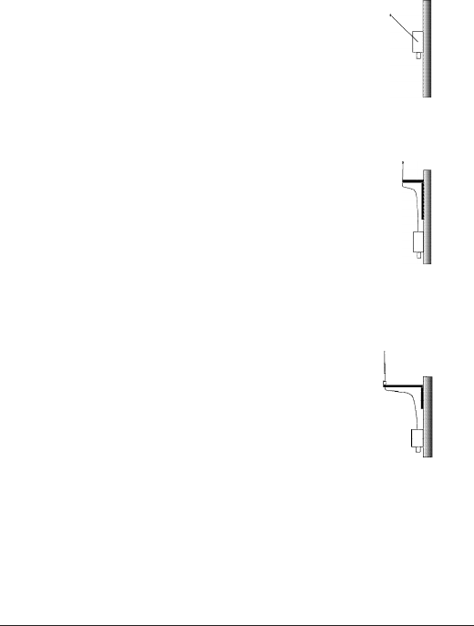
Place the antenna:
• check that there is a good connection between the antenna and the
material on which it has been installed.
• check that the antenna aerial and any coaxial cables are
undamaged and that the antenna is directed upwards.
• the 1/2-wave antenna is ground plane independent. If the
receiver is installed on a wall, the antenna should be angled
out from the wall
• the 1/4-433K antenna with a 3 metres coaxial cable is for
high and unobstructed placement. For optimum range, install on a at
roof, free from other metal objects and antennas. When installing the
antenna on a vehicle, use a vehicle bracket.
• the 5/8-wave antenna with a 3 metres coaxial cable for high and
unobstructed placement. For optimum range, install on a at roof, free
from other metal objects and antennas. When installing the antenna on a
wall, use a wall bracket.
1/2
1/4-433K
5/8
12
START THE TRANSMITTER
1. Pull out the STOP button.
2. Press the Start-buttons 11+12 at the same time for more than 1
second.
The transmitter top LED lights.
(With a PIN code: Enter the PIN code (4 digits).
The transmitter top LED lights.
TURN THE TRANSMITTER OFF
1. Press the Stop-button.
NOTE! All relays deactivate when the stop button is being pressed.
REGISTER THE TRANSMITTER IN THE
RECEIVER
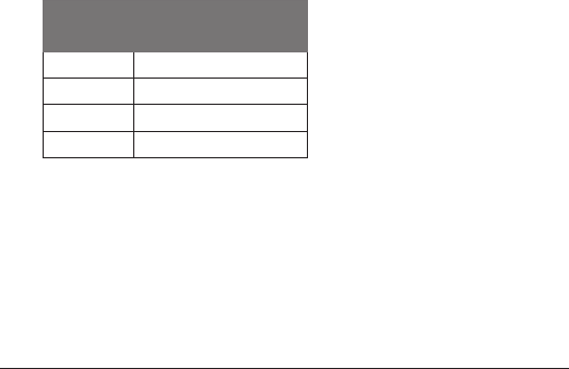
1-3 transmitters can be registered in each receiver. Each transmitter has
a unique ID code. Receiver LEDs 6 + 10 flash to indicate the number of
transmitters that are registered:
NO. OF
FLASHES
NO. OF REGISTERED
TRANSMITTERS
0 0
1 1
2 2
3 3
1. Place the receiver Function selector switch in ON position.
2. Press the receiver Reset button, and keep pressed.
Receiver LEDs 4-6, 8-10 light.
3. Release the Reset button. Receiver LEDs 4, 8, 5, 9 go out.
4. Start the transmitter.
5. Press the Start-buttons again until receiver LEDs 6 + 10 start to
ash.
6. Place the receiver Function selector switch in OFF position.

13
ERASE THE TRANSMITTER FROM THE
RECEIVER
1. Place the Function selector switch on the receiver in ON position.
2. Press the reset button on the receiver and keep pressed.
Receiver LEDs 4, 8, 5, 9 light.
3. Release the reset button. Receiver LEDs 4, 8, 5, 9 go out.
4. Place the Function selector switch on the receiver in OFF position.
5. WITHIN 2 SECONDS: Place the Function selector switch on the
receiver in ON position. Receiver LEDs 6+10 ash.
6. Place the Function selector switch on the receiver in OFF position.
SWITCH FREQUENCY
1. Press the Start-buttons 11+12 at the same time for more than 1
second. Release button 11. Keep button 12 pressed.
2. WITHIN 0.3 SECONDS: Release button 12. Press button 2.
The red transmitter LED 2 lights. The transmitter top LED ashes.
3. Enter the safety code: 1, 2, 3, 4 (NOTE! Maximum 5 seconds per
button).
The transmitter LED 2 goes out. The transmitter top LED ashes.
4. Select channel. E.g. for channel 02: Press button 0. Release. Press
button 2.
The red transmitter LED 2 ashes 3 times to conrm the change of frequency.
5. Restart the transmitter.

14
01 433,075 MHz 36 433,950 MHz
02 433,100 MHz 37 433,975 MHz
03 433,125 MHz 38 434,000 MHz
04 433,150 MHz 39 434,025 MHz
05 433,175 MHz 40 434,050 MHz
06 433,200 MHz 41 434,075 MHz
07 433,225 MHz 42 434,100 MHz
08 433,250 MHz 43 434,125 MHz
09 433,275 MHz 44 434,150 MHz
10 433,300 MHz 45 434,175 MHz
11 433,325 MHz 46 434,200 MHz
12 433,350 MHz 47 434,225 MHz
13 433,375 MHz 48 434,250 MHz
14 433,400 MHz 49 434,275 MHz
15 433,425 MHz 50 434,300 MHz
16 433,450 MHz 51 434,325 MHz
17 433,475 MHz 52 434,350 MHz
18 433,500 MHz 53 434,375 MHz
19 433,525 MHz 54 434,400 MHz
20 433,550 MHz 55 434,425 MHz
21 433,575 MHz 56 434,450 MHz
22 433,600 MHz 57 434,475 MHz
23 433,625 MHz 58 434,500 MHz
24 433,650 MHz 59 434,525 MHz
25 433,675 MHz 60 434,550 MHz
26 433,700 MHz 61 434,575 MHz
27 433,725 MHz 62 434,600 MHz
28 433,750 MHz 63 434,625 MHz
29 433,775 MHz 64 434,650 MHz
30 433,800 MHz 65 434,675 MHz
31 433,825 MHz 66 434,700 MHz
32 433,850 MHz 67 434,725 MHz
33 433,875 MHz 68 434,750 MHz
34 433,900 MHz 69 434,775 MHz
35 433,925 MHz
NOTE! The receiver automatically switches to the new frequency.
FREQUENCY TABLE 1 (69 CHANNELS)
15
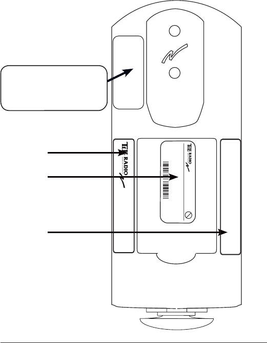
PLACEMENT OF LABELS WITH IC AND FCC
INFORMATION
1. FCC statement label
2. IC label
3. Product label
4. FCC ID label
1
2
3
4
3. FCC ID label is
placed in the battery
compartment behind
the battery. See page 7
for how to remove the
battery.
This device complies with part 15 of the
FCC rules. Operation is subject to the
following two conditions: (1) This device
may not cause harmful interference, and
(2) this device must accept any interfer-
ence received, including interference
that may cause undesired operation.
FCC ID: ONFC1013A
www.tele-radio.com
IC: 4807A-C1013A
Model No: T00003-20
Pb
Type: T00003-20
Freq.: 433.075 - 434.775 MHz
Serial no.:<TOM>
IC: 4807A-C1013A
FCC ID: OMFC1013A
This device complies with part 15 of the
FCC rules. Operation is subject to the
following two conditions: (1) This device
may not cause harmful interference, and
(2) this device must accept any interfer-
ence received, including interference
that may cause undesired operation.

16
FCC STATEMENTS
THIS DEVICE COMPLIES WITH PART 15 OF THE FCC RULES.
OPERATION IS SUBJECT TO THE FOLLOWING TWO CONDITIONS:
1. THIS DEVICE MAY NOT CAUSE HARMFUL INTERFERENCE
2. THIS DEVICE MUST ACCEPT ANY INTERFERENCE THAT MAY CAUSE UNDE-
SIRED OPERATION. NOTE: THE MANUFACTURER IS NOT RESPONSIBLE FOR
ANY RADIO OR TV INTERFERENCE CAUSED BY UNAUTHORIZED MODIFI-
CATIONS TO THIS EQUIPMENT. SUCH MODIFICATIONS COULD VOID THE
USER´S AUTHORITY TO OPERATE THE EQUIPMENT.
THIS EQUIPMENT COMPLIES WITH FCC RADIATION EXPOSURE LIMITS SET
FORTH FOR AN UNCONTROLLED ENVIRONMENT. END USER MUST
FOLLOW THE SPECIFIC OPERATING INSTRUCTIONS FOR SATISFYING RF
EXPOSURE COMPLIANCE. THIS TRANSMITTER MUST NOT BE CO-LOCATED
OR OPERATING IN CONJUNCTION WITH ANY OTHER ANTENNA OR
TRANSMITTER.
RADIO TRANSMISSION
The transmitter buttons have 2 steps. Both steps transmit radio
continuously when being pressed. When released the radio stops
transmitting within 5 seconds.
GUARANTEE, SERVICE, REPAIRS AND
MAINTENANCE
The Tele Radio products are covered by a guarantee against material,
construction and manufacturing faults. During the guarantee period, Tele
Radio may replace the product or faulty parts. Work under guarantee
must be carried out by Tele Radio or by an authorized service centre
specied by Tele Radio. This is not covered by the guarantee: Faults result-
ing from normal wear and tear. Parts of a consumable nature. Products
that have been subject to unauthorized modications. Faults resulting
from incorrect installation and use. Damp and water damage. Repairs
and maintenance must be carried out by qualied personnel. Use spare
parts from Tele Radio only. Contact your representant or HelpDesk if you
require service or other assistance. Keep the product in a dry, clean place.
Keep contacts and antennas clean. Wipe off dust using a slightly damp,
clean cloth. Never use cleaning solutions or high-pressure water.

17
Battery, Electronics, Disposal And Recycling
BATTERY, ELECTRONICS, DISPOSAL AND
RECYCLING
PRECAUTIONS
Observe the following warnings.
• As batteries contains ammable substances such as lithium or other
organic solvents, they may cause heating, rupture or ignition.
• Risk of explosion if battery is replaced with a battery of an incorrect
type.
• Do not short circuit, disassemble, deform or heat batteries.
• Never try to charge a visibly damaged or frozen battery.
• Do not charge rechargeable batteries with a higher voltage than
specied.
• Keep batteries out of reach of small children. Should a child swallow
a battery, consult a physician immediately.
• Avoid direct soldering to batteries.
• When discarding batteries, insulate the + and - terminals of batter-
ies with insulating/ masking tape. Do not put multiple batteries in the
same plastic bag.
• When improperly disposed, lithium batteries may short circuit, caus-
ing them to become hot, burst or ignite.
• Store in a cool location. Keep batteries away from direct sunlight,
high temperature, and high humidity.
• Do not throw batteries into re.
BATTERY DATA
BATTERY TYPE: External and rechargeable lithium-ion
CHARGE: In the charger unit 5V DC ±10% (1A)
CHARGING
TEMPERATURE: 0°C to 45°C/32°F to 113°F
OPERATING TIME: Approx. 24 h. with continuous usage

18 Battery, Electronics, Disposal And Recycling
• Before using the transmitter for the rst 3-4 times, make sure that the
battery is fully charged.
• When it´s time to charge the battery, the internal buzzer beeps 3 times,
and the top LED turns red (when approx. 10% of the battery capacity
remains).
• The top LED remains red during charging. When the top LED turns
green, the battery is fully charged ( approx. 4 hours).
• The battery can not be overcharged.
• We recommend that you use your battery at least once a month. If you
for some reason won´t use it for a longer period, store in a cool, dry
and clean place. Before starting to use the battery again, make sure that
it is fully charged.
NOTE! The transmitter must be on to check the battery status.
PLACEMENT OF BATTERY
The battery is placed in the back of the transmitter.
DISPOSAL OF BATTERIES AND ELECTRONICS
Batteries and electronic waste may contain toxic heavy metals. If thrown
away in the trash, the toxic compounds can leach into soil
and water, pollute lakes and streams, making them unt
for drinking, swimming, shing, and wildlife. A lithium-ion
battery does not contain mercury, cadmium or lead and is
better for the environment than older types of
batteries. Rechargeable batteries last considerably longer
than single-use batteries, so using them means fewer
batteries for disposal. Even rechargeable batteries have a
nite life span and shall be recycled. Contact your local
government’s recycling or solid waste department for more information
on proper disposal of batteries and electronics in your region.
TELE RADIO SVERIGE
Sweden
Tel. +46 (0)31-724 98 00
e-mail: sverige@tele-radio.com
TELE RADIO GmbH
Germany
Tel. +49 (0)94 51-944 8 550
e-mail: deutschland@tele-radio.com
TELE RADIO ASIA
China
Tel. +86-(0)592-3111168
e-mail: china@tele-radio.com
TELE RADIO TURKEY
Turkey
Tel. +90 216 574 22 94
e-mail: turkiye@tele-radio.com
TELE RADIO LTD
England
Tel. +44 (0) 1625 509125
e-mail: england@tele-radio.com
TELE RADIO LLC
North America & Latin America
Tel. +1 (305) 459 0763
e-mail: america@tele-radio.com
TELE RADIO BV
Benelux
Tel. +31-(0)70-419 41 20
e-mail: benelux@tele-radio.com
TELE RADIO AS
Norway
Tel. +47-6933 4900
e-mail: norge@tele-radio.com
TELE RADIO AB
Sweden, Main office
Tel. +46 (0)31-748 54 60
e-mail: info@tele-radio.com
www.tele-radio.com