Tele Radio C1104B Radio module User Manual ONFC1104B 4807A C1104B Rev3
Tele Radio AB Radio module ONFC1104B 4807A C1104B Rev3
ONFC1104B & 4807A-C1104B User Manual Rev3
Tele Radio
FCC-IM-TG-RX005-B03-EN
ARTICLE CODE: R00004-03, R00004-08, T00012-07, T00012-52
LANGUAGE: ENGLISH (ORIGINAL)
SAFETY INSTRUCTIONS
Thank you for purchasing a Tele Radio product
R00004-03, R00004-08, T00012-07, T00012-52
READ ALL INSTRUCTIONS CAREFULLY BEFORE MOUNTING, INSTALLING AND
CONFIGURATING THE PRODUCT.
These instructions are published by Tele Radio AB without any guarantee. These
instructions are solely directed towards qualied installers. The information shall not be
handed to end users. The instructions may be removed or revised by Tele radio AB at
any time and without any further notice. Corrections and additions will be added to the
updated versions of the instructions.
The instructions that contain information on the installation and conguration of the
remote radio control unit on the machine are not intended to be passed on to the end
user. Only such information may be passed on to the end user, that is needed to operate
the machine correctly by radio remote control.
Tele Radio AB products are covered by a guarantee against material, construction or
manufacturing faults. During the guarantee period, Tele Radio AB may replace the product
or faulty parts with new. Work under guarantee must be carried out by Tele Radio AB
or by an authorized service centre specied by Tele Radio AB. Make sure that repairs and
maintenance are only carried out by qualied personnel. Use only spare parts from Tele
Radio AB. Contact your Tele Radio representative if you need support or service.
©Tele Radio AB, 2011
TELE RADIO AB
Datavägen 21, SE-436 32 Askim. Sweden
Tel: +46-31-748 54 60
Fax: +46-31-68 54 64
www.tele-radio.com.
info
@
tele-radio.com

3
RECEIVER
TECHNICAL DATA
Maximum current consumption
RX MODEL 12 V DC 24V DC 48V AC 230V AC
R00004-03 280 mA 140 mA 140 mA 20 mA
R00004-08 500 mA 240 mA 230 mA 50mA
RELAYS:
R00004-03 2 safe relays (makes/breaks
16A ACI) + 7 function relays (potential
free*,makes/breaks 8A ACI).
R00004-08 2 safe relays (makes/breaks
16A ACI) + 17 function relays (potential
free*,makes/breaks 8A ACI).
OPERATING FREQUENCY: 903.0125-926.9875 MHz.
FREQUENCY BANKS: 15 banks
SIZE: 75 x 126 x 176 mm./
29.5” x 49.6” x 69.3”
WEIGHT: 1000 grams/ 2.2 lbs.
ENCAPSULATION IP CLASS: IP65
* potential free means that you have to supply voltage to get voltage out of a relay (e.g. via a
connection comb).
IMPORTANT! We recommend that the functionality of the STOP button is being
tested at a regular basis: At a minimum, when used for 200 hours. Test the STOP
button by pressing and pulling it out.
STOP BUTTON TEST
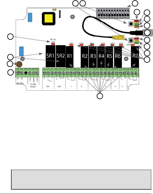
4
1. Stop relays 1+2 LED (red)
2. Stop relays 1+2
3. Obligatory fuse: 2A (slow), must
comply with IEC691/EN60691
4. Terminal block for power supply
(see next page)
5. Function relays 1-7
6. Relay LEDs1-7 (red)
7. Function LED 7 (green)
8. Function LED 6 (yellow)
9. Function LED 5 (red)
10. Antenna connector
11.Function LED 4 (orange)
12. Function LED 3 (green)
13. Function LED 2 (yellow)
14. Function LED 1 (red)
15. Terminal block for mixed I/Os
16. Function button
(Cancel button)
17. Select button (OK button)
2
3
4
5
6
7
9
11
12
13
8
14
15
1617
10
1
RECEIVER TG-R00004-03, TG-R00004-08
BASE BOARD
IMPORTANT!
Tele Radio remote controls are often built into wider applications. We recommend that
the system is provided with a wired emergency stop where necessary.
5
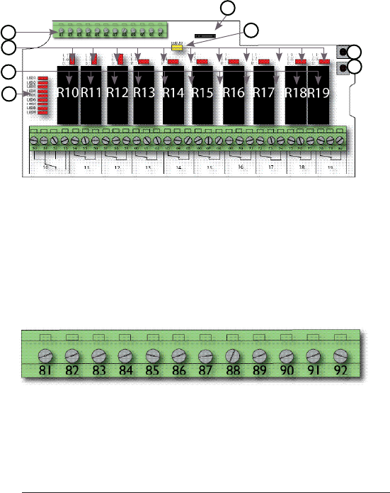
TG-R00004-08
10 RELAYS EXPANSION BOARD
81. GND
82. GND
83. GND
84. GND
85. Digital input 3
86. Digital input 4
87. Digital input 5
88. Digital input 6
89. Digital input 7
90. Digital input 8
91. Digital input 9
92. Digital input 10
18. Terminal block for digital inputs
19. Relay LEDs 10-19
20. Function relays 10-19
21. Relay LEDs 1-9 (see next page)
22. Select button (OK)
23. Function button (Cancel)
24. Base board communication-
LED (yellow)
25. Programming connector
18. Terminal block for digital inputs
18
20
21
23
24
25
22
19

6
LED 1
LED 2
LED 3
LED 4
LED 5
LED 6
LED 7
LED 8
LED 9
LED 1= function relay 1
LED 2= function relay 2
LED 3= function relay 3
LED 4= function relay 4
LED 5= function relay 5
LED 6= function relay 6
LED 7= function relay 7
LED 8= not used
LED 9= stop relay 1+2
LEDs 1-9 on the expansion board indicate the status of the relays on the
base board. When one or more of these LEDs are lit, the corresponding
relay on the base board is activated (see list).
21. Relay LEDs 1-9
7
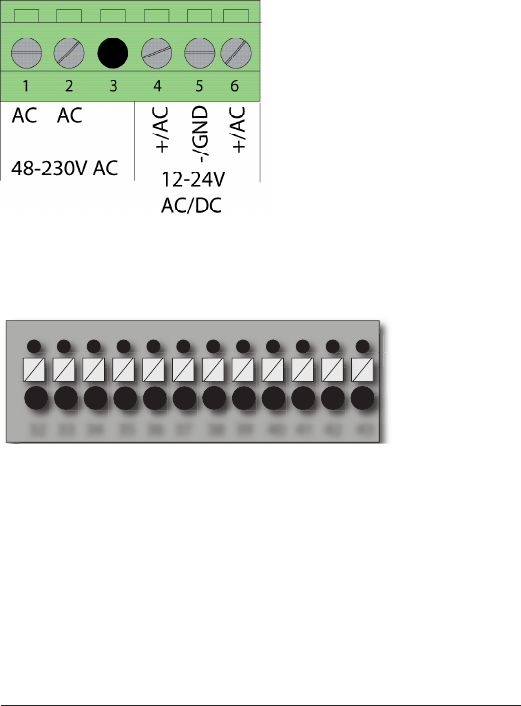
32 33 34 35 36 37 38 39 40 41 42 43
1. 48-230V AC
2. 48-230V AC
3. (not used)
4. 12-24V AC/DC
5. GND
6. 12-24V AC/DC
32. +12V DC
33. +5V DC
34. GND
35. GND
36. Digital input 1
37. Buzzer
38. Digital input 2
39. GND
40. +3.3V DC
41. RS485A
42. RS485B
43. GND
15. Terminal block for mixed I/Os
4. Input power
For DC voltages:
Connect positive voltage to 4 or 6. Connect negative voltage to 5.
8
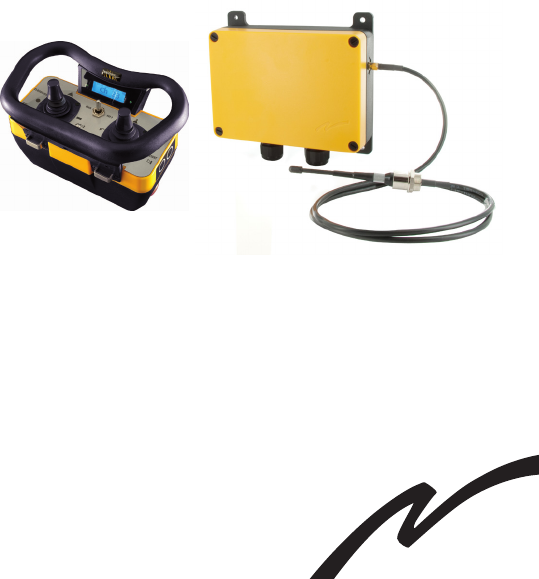
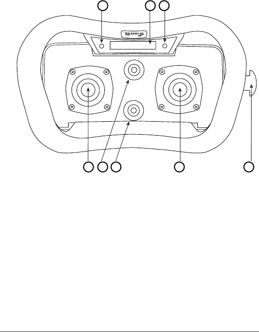
DISPLAY
1. Left joystick
2. Front switch
3. Function switch
4. Right joystick
5. Stop button
6. Red/green LED 1
7. Display
8. Red/green LED 2
1 2 3 4 5
876
TRANSMITTER
JOYSTICK T00012-07, T00012-52
9
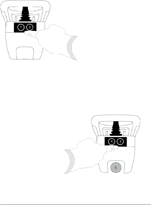
LEFT SIDE
RIGHT SIDE
3. Side Button 3 (start button)
4. Side Button 4 (start + safe button)
5. STOP button
1. Side button 1
2. Side button 2 (safe button)

10
START UP IN OPERATING MODE
1. Pull out the STOP button.
The green/red LEDs 1+2 light up: in green when the battery capacity
is good, in red when the battery needs to be charged. See how to
charge the battery in “Battery-how to charge”.
2. Select a receiver for the current session by using the left joystick.
3. Press the side buttons 3+4 until the buzzer sounds and LED 1+2
starts to ash.
TURN OFF
1. Press the STOP button. The joystick is now turned off.
NOTE! All relays disconnect when the STOP button is
pressed.
ENTER THE TRANSMITTER CONFIGURATION MENU
1. Pull out the STOP button.
The green/red LEDs 1+2 light up: in green when the battery capacity
is good, in red when the battery needs to be charged. See how to
charge the battery in “Battery-how to charge”.
2. Press button 3. Keep pressed.
3. Press the STOP button.
4. Release button 3.
The menu shows in the display. LED 1+2 starts to ash in green.
EXIT THE TRANSMITTER CONFIGURATION MENU
1. Press button 3. The joystick transmitter turns itself off.
11
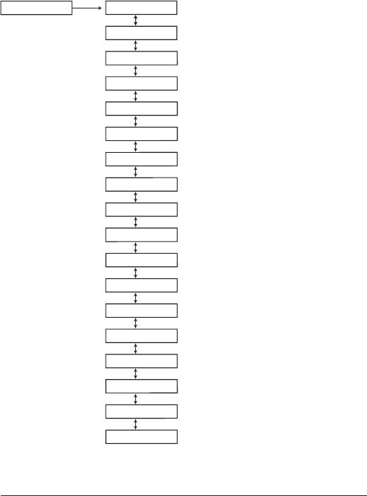
TRANSMITTER CONFIGURATION MENU MAP
>Channel/Bank
>Register
SETTINGS>
>Logout
>Erase
>Replace
>Show receivers
>Auto shutdown
>Load selection
>Startup protection
>Settings protection
>Learn RFID
>Show RFID
>Erase RFID
>Enter PIN
>Show PIN
>Erase PIN
>Show SW vers.
>Test mode

12
NAVIGATE IN THE CONFIGURATION MENU
• TO MOVE UP AND DOWN: Move the left joystick up and down.
• TO SELECT: Press button 4.
• TO GO BACK: Move the left joystick to the left.
• TO EXIT: Press button 3 or pull out the STOP button. The
transmitter will turn off.
SWITCH FREQUENCY BANK
1. Pull out the STOP button. LEDs 1+2 light.
2. Press button 3. Keep pressed.
3. Press the STOP button.
4. Release button 3. The conguration menu opens.
5. Navigate to ”Channel/bank” by scrolling down with the left joystick.
6. Select by pressing button 4.
7. Navigate to the bank that you want to switch to.
8. Select bank by pressing button 4.
When you restart the transmitter, it will transmit on the channels included in
the selected bank. The receiver will automatically detect and switch to the same
frequency as the transmitter.
REGISTER THE JOYSTICK IN THE RECEIVER
You can register 1-15 TIGER transmitters in a TIGER receiver. Each
transmitter has a unique ID code.
1. Pull out the STOP button. LEDs 1+2 light.
2. Press button 3. Keep pressed.
3. Press the STOP button.
4. Release button 3. The conguration menu opens.
5. Navigate to ”Register”.
6. Select a slot for the transmitter to be stored in (slot 1-15).

13
7. Put the receiver in registering mode:
a. Press the receiver Function button.
b. Press the receiver Select button.
c. All the receiver relay LEDs light red when the receiver is in
registering mode.
Wait until the joystick display shows ”Conrm on RX”, which may take up
to 15 seconds.
8. Conrm by pressing the receiver Select button.
All receiver relay LEDs ash in red 3 times.
9. The joystick turns itself off.
IMPORTANT! For safety reasons, avoid registering transmitters
in receivers where you don´t intend to use it.
ERASE THE TRANSMITTER FROM THE RECEIVER
IMPORTANT! Do not perform the erase function during a
running session.
NOTE ! The receiver must be powered during the erase function.
1. Pull out the STOP button. LEDs 1+2 light.
2. Press button 3. Keep pressed.
3. Press the STOP button.
4. Release button 3. The conguration menu opens.
5. Navigate to ”Erase”.
6. Select the receiver that you want to erase.
The joystick display will show: ”OK” when the receiver has been erased.
The joystick transmitter turns itself off.
14
CHARGE THE BATTERY
BATTERY TYPE: External and rechargeable
CHARGE: In a charger unit. 5V DC ±10% (1A)
CHARGING TEMPERATURE: 0°C to 45°C/ 32°F to 113°
OPERATING TIME: Approx. 15 h. with continuous usage
Approx. 27 h. when the display is off
SIZE: 256 x 217 x 85 mm.
10 x 8.5 x 3.3 in.
• Before using the joystick for the rst time, make sure that the
battery is fully charged.
• When it´s time to charge the battery, the transmitter LED 1+ 2
turn red and the buzzer beeps 3 times.
• When the battery is fully charged, the LED on the charger unit will
go from red to green (approx. 4 h.).
• The battery can not be overcharged.
• The display monitors the battery status.
NOTE! The joystick must be on to check the battery status.
CHARGING
UNIT
LED

15
FCC AND IC INFORMATION
Caution: The user is cautioned that changes or modications not
expressly approved by the party responsible for compliance could void
the user’s authority to operate the equipment.
This device complies with Industry Canada licence-exempt RSS
standard(s) and Part 15 of the FCC Rules. Operation is subject to
the following two conditions: (1) this device may not cause harmful
interference, and (2) this device must accept any interference received,
including interference that may cause undesired operation.
Le présent appareil est conforme aux CNR d’Industrie Canada applica-
bles aux appareils radio exempts de licence et la partie 15 des Règles
FCC. L’exploitation est autorisée aux deux conditions suivantes :
(1) l’appareil ne doit pas produire de brouillage, et
(2) l’utilisateur de l’appareil doit accepter tout brouillage radioélec-
trique subi, même si le brouillage est susceptible d’en compromettre le
fonctionnement.
This equipment complies with FCC radiation exposure limits set forth
for an uncontrolled environment. End user must follow the specic
operating instructions for satisfying RF exposure compliance. This
transmitter must not be co-located or operating in conjunction with
any other antenna or transmitter.
Cet appareil est conforme aux limites d’exposition au rayonnement RF
stipulées par la FCC et l’IC pour une utilisation dans un environnement
non contrôlé. L’utilisateur nal doit suivre les instructions de fonction-
nement spéciques pour le respect d’exposition aux RF. Lesémetteurs
ne doivent pas être placées près d’autres antennes ou émetteurs ou
fonctionner avec ceux-ci.
The radio module in this product is labelled with its own FCC ID and
IC number. The FCC ID and IC is not visible when the radio module is
installed inside another device. Therefore, the outside of the device into
which the module is installed must also display a label referring to the
radio module. The nal end device must be labelled in a visible area with
the following:
“Contains FCC ID: ONFC1104A”
“Contains IC: 4807A-C1104A”
or
“Contains FCC ID: ONFC1104B”
“Contains IC: 4807A-C1104B”
16
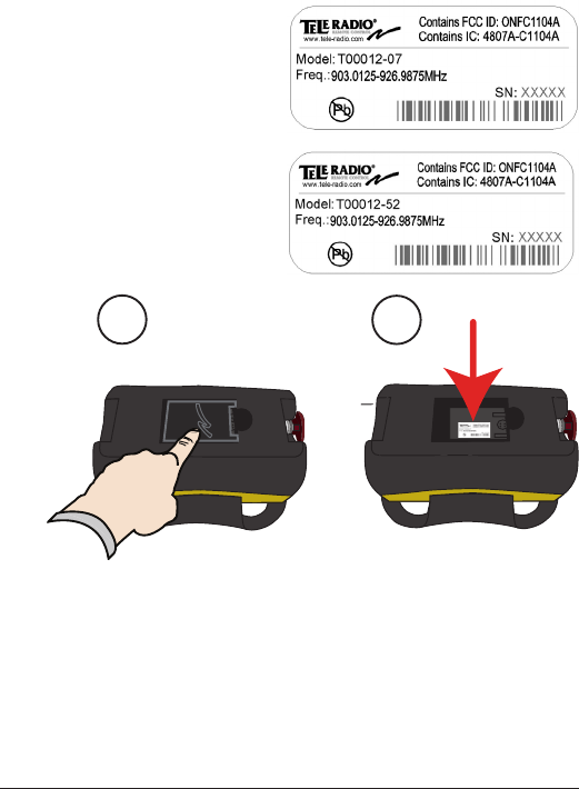
TRANSMITTER PRODUCT LABEL
PLACEMENT
TIGER
12
TIGER
1. Remove the battery from the bottom of the joystick.
2. The product label with FCC/ IC information is placed under the
battery.
17
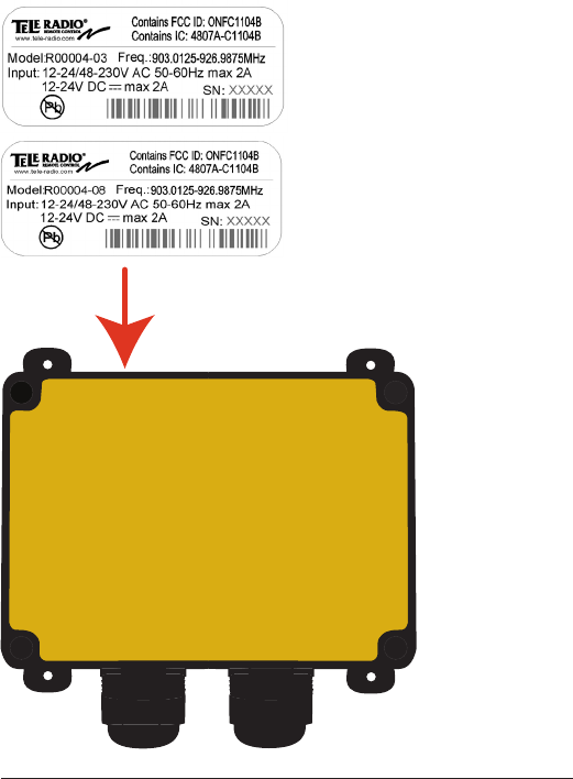
RECEIVER PRODUCT LABEL PLACEMENT
18
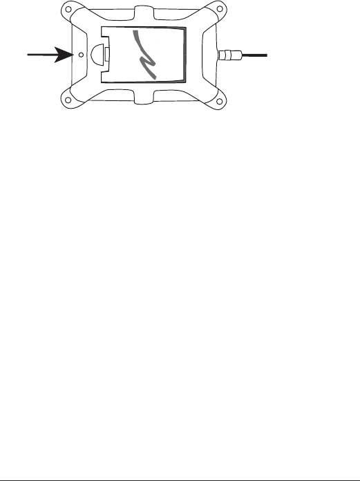
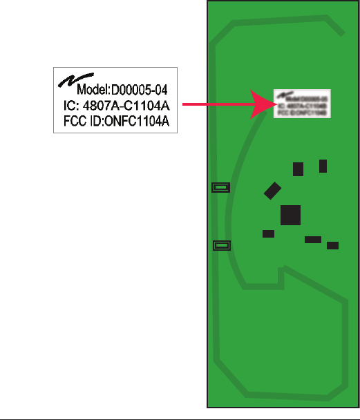
FCC/ IC LABEL PLACEMENT ON
TRANSMITTER
The FCC/ IC label is placed on the radio module. The radio module is
mounted inside the transmitter.
L’étiquette FCC/IC est placée sur le module radio. Le module radio est
monté à l’intérieur du récepteur.
19
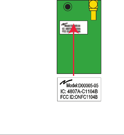
FCC/ IC LABEL PLACEMENT ON RECEIVER
The FCC/ IC label is placed on the radio module. The radio module is
mounted inside the receiver.
L’étiquette FCC/IC est placée sur le module radio. Le module radio est
monté à l’intérieur de l’émetteur.

20
THE RADIO MODULE
FUNCTION
Each receiver and transmitter unit in the Tele Radio Tiger product
range, contains a radio module that is specically designed to match a
Tele Radio Tiger unit in terms of physical dimensions, connection points,
voltage levels, signal interface etc. To use the radio modules in non Tele
Radio products is not permitted.
The radio modules are designed to interface directly to the main board
of the receiver/transmitter unit. They are power supplied by the main
board and the radio circuit operates strictly according to instructions
from a microprocessor on the main board. The radio circuit cong-
uration is stored in a ash memory on the radio module.
A receiver/transmitter unit with a defective/no radio module will give
an error message immediately after power up, and it will not be
possible to start a radio session.
CROSS REFERENCE
Cross reference of radio modules and corresponding products:
Tiger unit Radio module:
T0012-* TR236
R0004-* TR254

21
INSTALLATION
INSTALLATION INSTRUCTIONS FOR TR236:
1. Make sure that the transmitter unit is turned off.
2. Open the T0012-* enclosure.
3. Connect the antenna cable from the main board to the 1x15 pole pin
connector on TR236.
4. Assemble TR236 in the bottom part of the enclosure. Assemble
TR236 so that the pin connector faces outwards.
INSTALLATION INSTRUCTIONS FOR TR254:
1. Make sure that the unit is turned off.
2. Open the R0004-* enclosure.
3. Connect the 2x12 pole socket connector of TR254 directly to the
main board of R0004-*.