Tele Radio C1203B Wireless Transceiver Radio Modular (D00005-09) User Manual CE TG2001 A01 EN
Tele Radio AB Wireless Transceiver Radio Modular (D00005-09) CE TG2001 A01 EN
ONFC1203B_User manual
RECEIVERS: R00004-05, R00004-10,
TRANSMITTERS: T00009-22, T00011-24
LANGUAGE: English (original)
IM-TG2-CE001-A01-EN
Installation instructions

CONTENTS
Chapter 1: CUSTOMER INFORMATION 3
Chapter 2: SYSTEM INFORMATION 5
Applicationareaforthe Tigersystem 5
Chapter 3: PRODUCT PAGES 6
Receiver R00004-05 6
Receiver R00004-10 with a relay expansion board 9
Transmitters T00009-22, T00011-24 13
Technical data 13
On/off switch 14
Chapter 4: FCC/ IC INFORMATION 15
FCC/IC INFORMATION for the T00011-24, R00004-10 15
Product label and placement on the transmitter 15
Product label and placement on the receiver 15
FCC/IC label and placement on the transmitter 16
FCC/ IC label placement on the receiver 16
The radio module 17
Installation 17
FCC statement 18
Chapter 5: INSTALLERS GUIDE 19
Create PIN codes 19
Erase PIN code 19
Show registered PIN codes 20
Start the transmitter in operating mode 20
Start the transmitter in operating mode with a PIN code 21
Navigate in menu mode 22
Login/logout 22
Quick logout 22
Logout from menu mode 22
Turn the transmitter off 23
Register 23
Register the transmitter in the receiver 23
Number of transmitters registered in the receiver 24
Erase 24
Erase a transmitter from the receiver 24
Replace 25
Replace a transmitter with a new transmitter 25
Automatic shutdown 26
Set the time for automatic shutdown 26
Frequencies & channels 26
Switch channel on the transmitter 26
Frequency band 2.4 GHz 27
Relay functionality 27
Momentary and latching relay functionality 27
Interlocking 28
Digital inputs 28
Chapter 6: BATTERY GUIDE 29
Battery information 29
Charge the battery 30
Removal of internal battery 31
Guarantee, service, repairs and maintenance 32
-2-

Chapter 1: CUSTOMER INFORMATION
CHAPTER 1: CUSTOMER INFORMATION
THANK YOU FOR PURCHASING A TELE RADIO AB PRODUCT
READALLINSTRUCTIONS ANDWARNINGS CAREFULLY BEFOREMOUNTING, INSTALLING
ANDCONFIGURATING THEPRODUCTS.
These instructions are published by Tele Radio AB without any guarantee. The instructions may be
removed or revised by Tele Radio AB at any time and without further notice. Corrections and additions
will be added to the latest version of the instruction.
IMPORTANT! The instructions that contain information on the installation and configuration of the
radio remote control unit on the machine are not intended to be passed on to the end user. Only such
information may be passed on to the end user that is needed to operate the machine correctly by radio
remote control.
Tele Radio AB products are covered by a guarantee/ warranty against material, construction or
manufacturing faults. During the guarantee/ warranty period, Tele Radio AB may replace the product or
faulty parts with new. Work under guarantee/ warranty must be carried out by Tele Radio AB or by an
authorized service center specified by Tele Radio AB. Contact your Tele Radio AB representative if you
need support or service.
©Tele Radio AB, 2012
Datavägen 21
SE-436 36 ASKIM
SWEDEN
Tel: +46-31-748 54 60
Fax: +46-31-68 54 64
www.tele-radio.com
-3-

WARNINGS & RESTRICTIONS
IMPORTANT! Tele Radio remote controls are often built into wider applications. We recommend that
the system is provided with a wired emergency stop where necessary.
NOTE! We recommend that the functionality of the STOP button is being tested at a regular basis: At a
minimum, when used for 200 hours. Test the STOP button by pressing it and pulling it out.
INSTALLING, CONNECTING AND MOUNTING
n Allow only licensed or qualified personnel to install the product.
n Switch the power supply off to the receiver before connecting the equipment.
n Check that you have connected the power supply to the correct connection terminal.
n To utilize the safety of the system, use the stop relays in the safety circuitry of the object that you
want to control.
n Use undamaged cables. No cables should hang loose.
n Avoid installing in areas affected by strong vibrations.
n Place the receiver well away from wind, damp and water.
n Cable glands and vent plugs must face down to prevent water from seeping in.
THE USER
n Make sure that the user is following the instructions.
n Make sure that the user has reached the certified age of your country to operate the equipment.
n Make sure that the user is not under the influence of drugs, alcohol and medicines.
n Allow only qualified personnel to have access to the transmitter and operate the equipment.
n Make sure that the user does not leave the transmitter unsupervised.
n Make sure that the user always turns the transmitter off when not in use.
n Make sure that the user keeps a good overview of the work area.
MAINTENANCE
n Use the stop button to start and turn off the transmitter as often as possible.
n When error messages are shown, it is very important to find out what caused them.
n If the stop button is mechanically damaged, contact your representative for service immediately.
n Always contact your representative for service and maintenance work on the product.
n Write down the serial numbers/ ID codes of the receivers and transmitters used. This infor-
mation should be recorded on the “Settings document” for your product (download from our
website).
n Avoid registering transmitters to receivers where it is not being used.
n Keep the safety instruction for future reference. Always download the configurations instruction
from our web site for the latest version available.
-4-

Chapter 2: SYSTEM INFORMATION
CHAPTER 2: SYSTEM INFORMATION
APPLICATION AREA FOR THE TIGER SYSTEM
The Tele Radio AB Tiger remote control systems are aimed for remote controlling of lifting or mobile
equipment where a high safety level is required.
AUTHORIZATION BY PIN CODE
To prevent from unauthorized users being able to start the transmitter and control the receiver, you can
enable PIN codes for start-up protection. 1-10 PIN codes can be stored in the T00009-22 and T00009-
24 transmitters.
SOFTWARE COMPATIBILITY CHECK
When a receiver and a transmitter are starting to communicate with each other, either for the first time
or after a loss of communication, a software compatibility check is performed. During this procedure the
base software versions and/or xApp software versions in both units are checked and verified. If
incompatible versions are detected, an error message will be indicated on both units´ LEDs.
Normally the incompatibility check will be performed automatically when the software has been
changed or when the units have lost contact. The transmitter needs to be manually restarted after
compatibility check when:
n the software is changed and the receiver restarts
n the receiver is restarted, e.g. because of loss of power, while the transmitter has been running
STOP FUNCTION
The transmitters have a stop button that controls the 2 stop relays in the receiver. 2 safety
microcontrollers are supervising and controlling the stop relays. A valid signal must be provided from
both microcontrollers to activate the stop relays.
ZERO POSITION CHECK
During start-up of the transmitter, a zero position check is performed. This means that when the stop
button has been pulled out and the start buttons are pressed, the transmitter will only start if no other
buttons are activated at the same time as the start buttons are pressed.
-5-
Chapter 3: PRODUCT PAGES
CHAPTER 3: PRODUCT PAGES
RECEIVER R00004-05
WARNING! The receiver must NOT be opened by any other than a qualified installer. Make sure to
turn the electricity off before opening the receiver.
IMPORTANT! Tele Radio remote controls are often built into wider applications. We recommend
that the system is provided with a wired emergency stop where necessary.
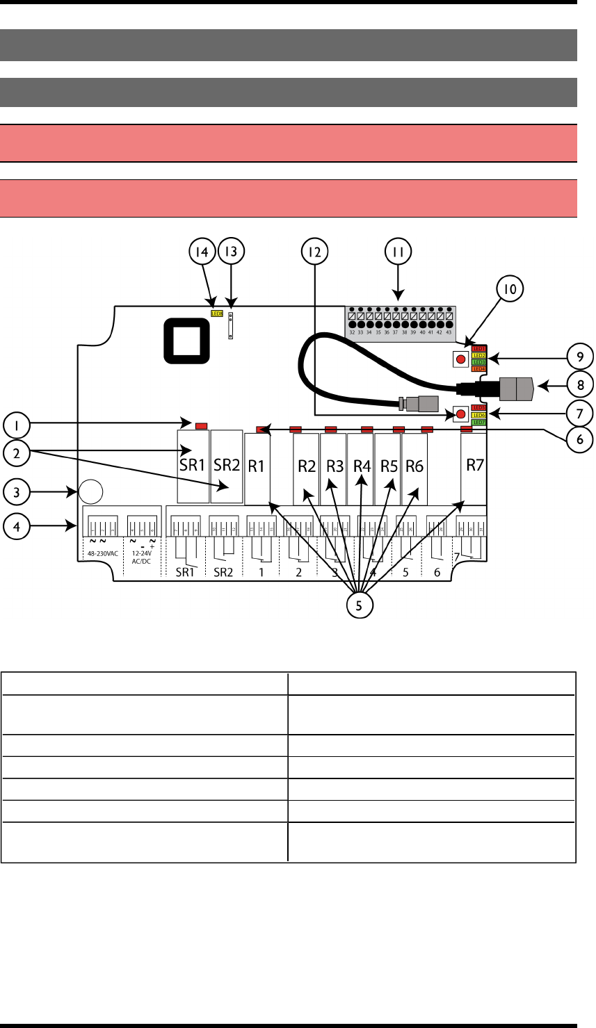
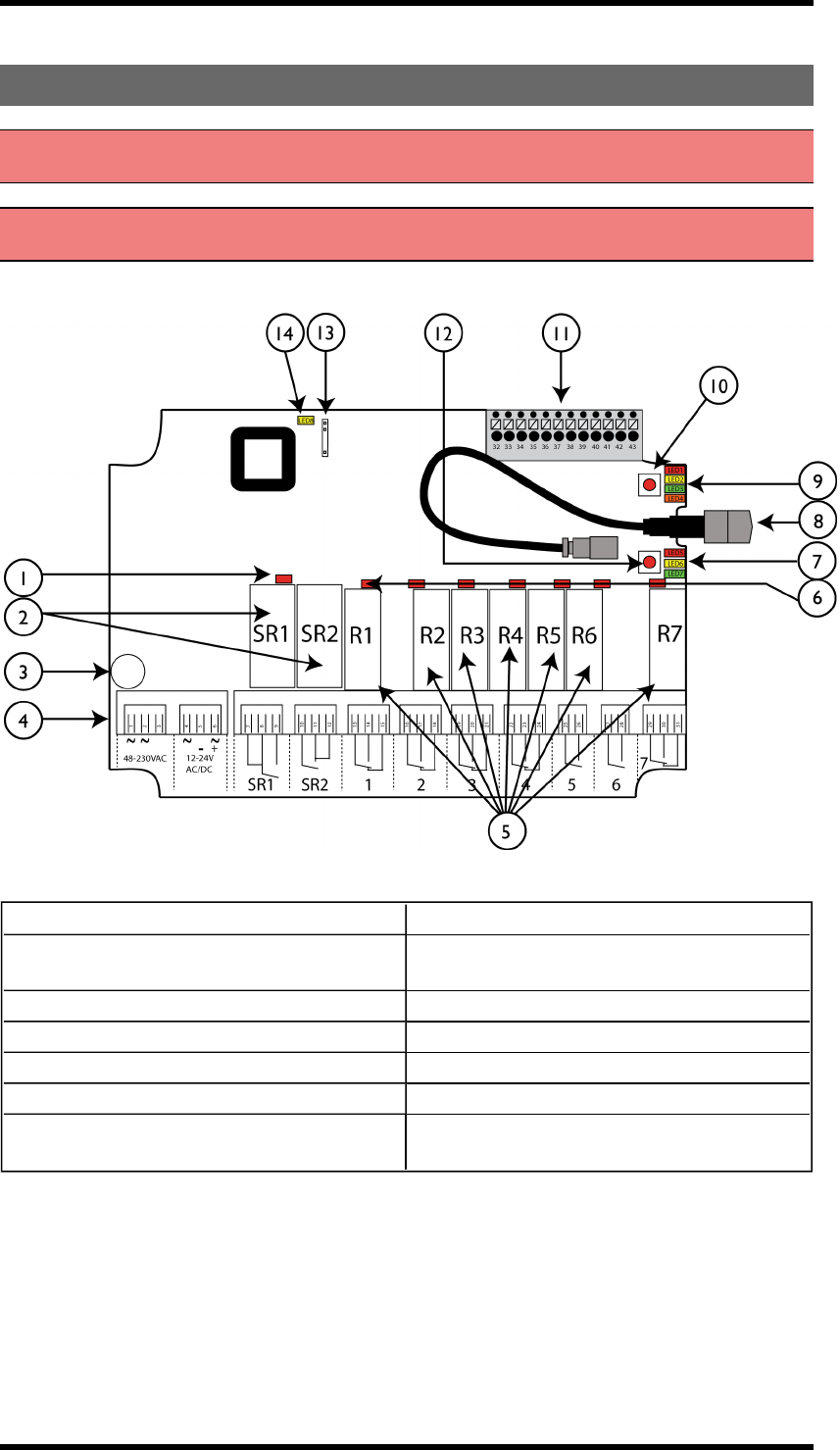
Base board:
1. LED representing stop relays 1+2 (red) 8. Antenna connector
2. Stop relays 1+2 9. Function LEDs 1-4 (1= red, 2= yellow, 3=
green, 4= orange)
3. Obligatory fuse 2A (slow) 10. Function button (Cancel)
4. Terminal block for input power 11. Terminal block for mixed I/O
5. Function relays 1-7 12. Select button (OK)
6. Relay LEDs 1-7 (red) 13. Programming connector
7. Function LEDs 5-7 (5= red, 6= yellow, 7=
green) 14. Power LED (yellow)
-6-
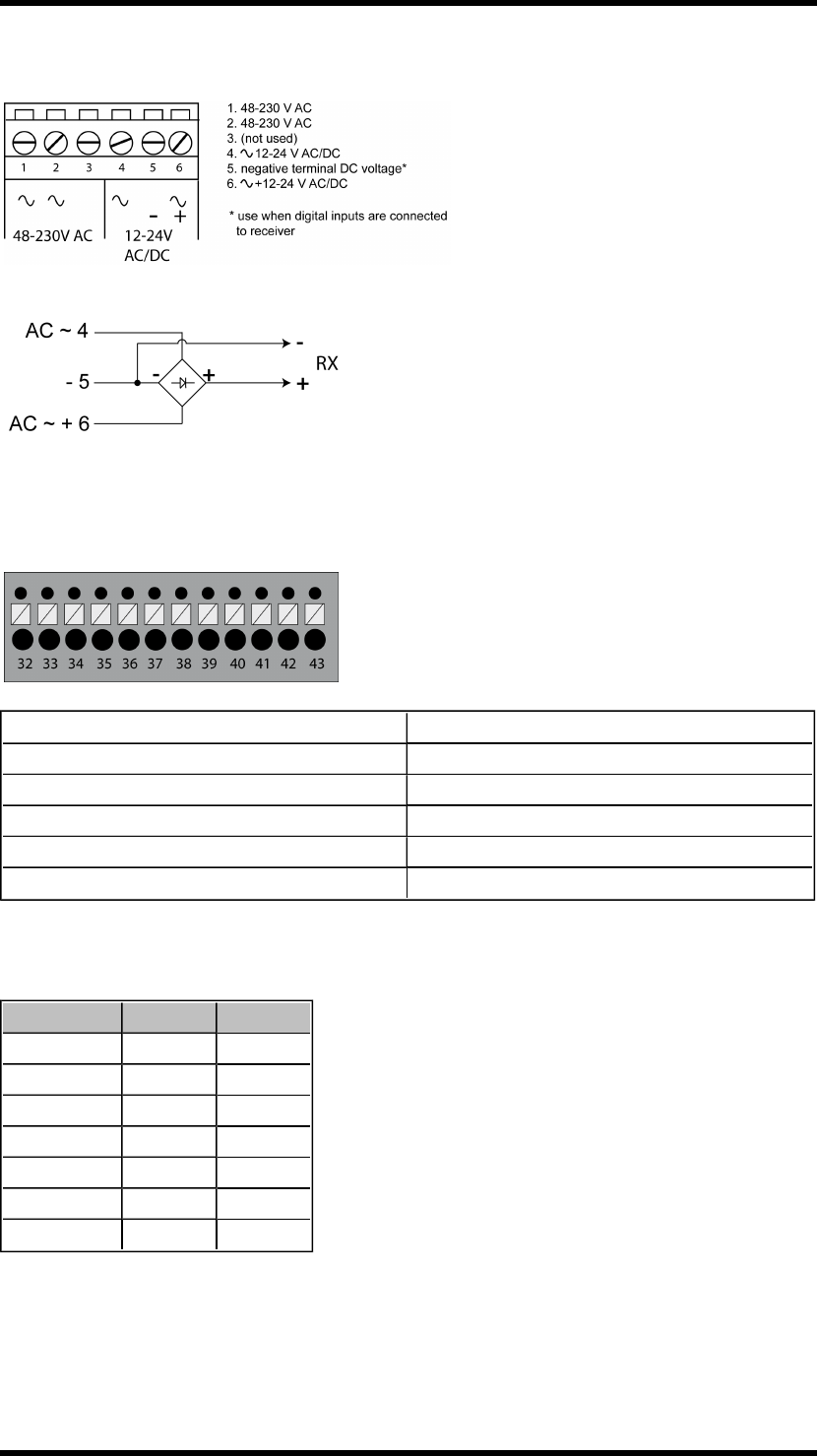
Terminal block for input power
Terminal block for mixed I/O
32. +12V DC 38. Digital input 2
33. +5V DC 39. GND
34. GND 40. +3.3V DC
35. GND 41. RS485A
36. Digital input 1 42. RS485B
37. Transistor output 43. GND
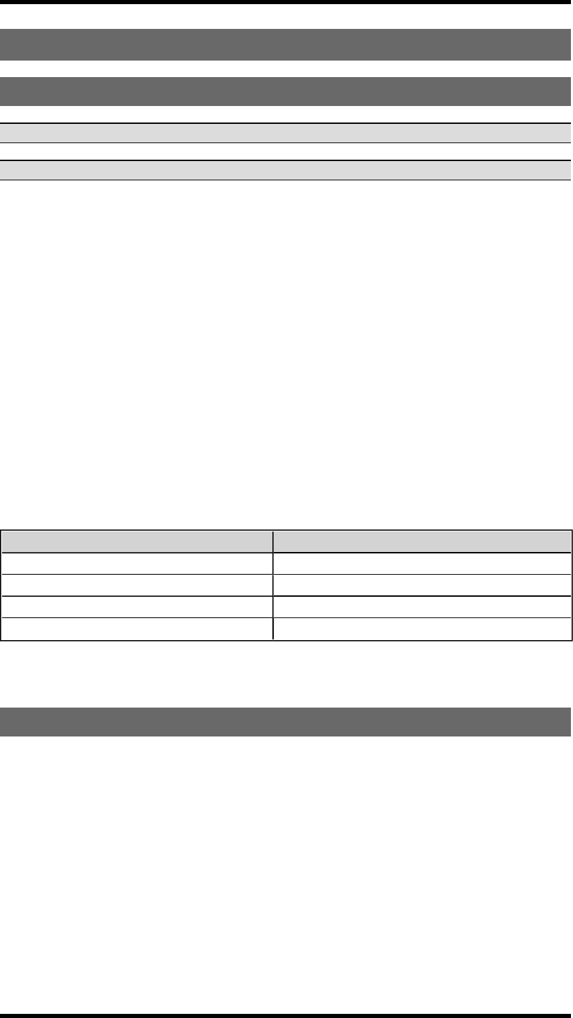
Current consumption
Input power Min.* Max.**
12V AC 0.06A 0.4A
24V AC 0.03A 0.2A
48V AC 0.02A 0.09A
115V AC 0.008A 0.04A
230V AC 0.006A 0.03A
12V DC 0.06A 0.3A
24V DC 0.03A 0.3A
* Minimum current consumption= Receiver powered, no radio session established, nothing else
activated on the receiver
** Maximum current consumption= All relays activated on the receiver
-7-
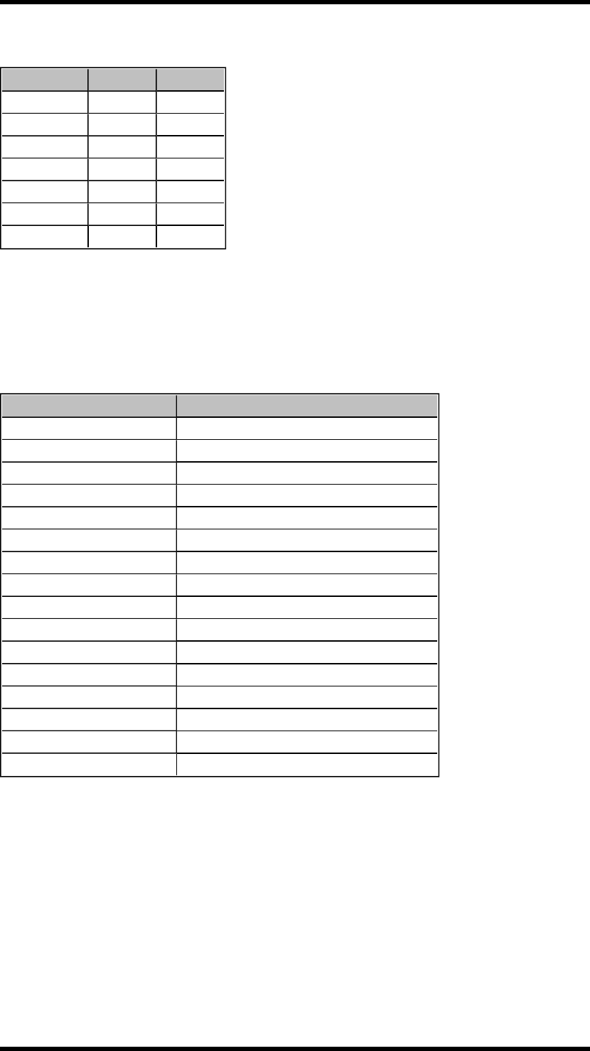
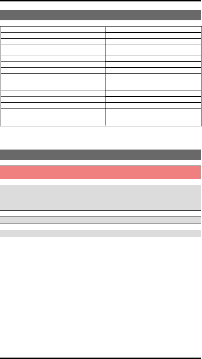
Technical data
R00004-05
Number of stop relays 2 (16A)
Number of function relays 7 (potential free*, 8A)
Digital inputs 2
Transistor output 1
Duplex communication Duplex or simplex communication possible
Max. number of transmitters 15
Operating frequency 2405-2480 MHz
Number of channels/ banks 16
Channel separation 5 MHz
IP class 66
Size 176 x 126 x 75 mm./ 6.9 x 5 x 2.9 in.
Weight 950 g./ 2.1 lbs
Radiotype Low IF topology
Sensitivity Better than -110 dBm
Antenna 1 external RPSMA antenna
Operating temperature -20- +55°C/ -4-+130°F
* potential free means that you have to supply voltage to get voltage out of a relay (e.g. via the included connection comb)
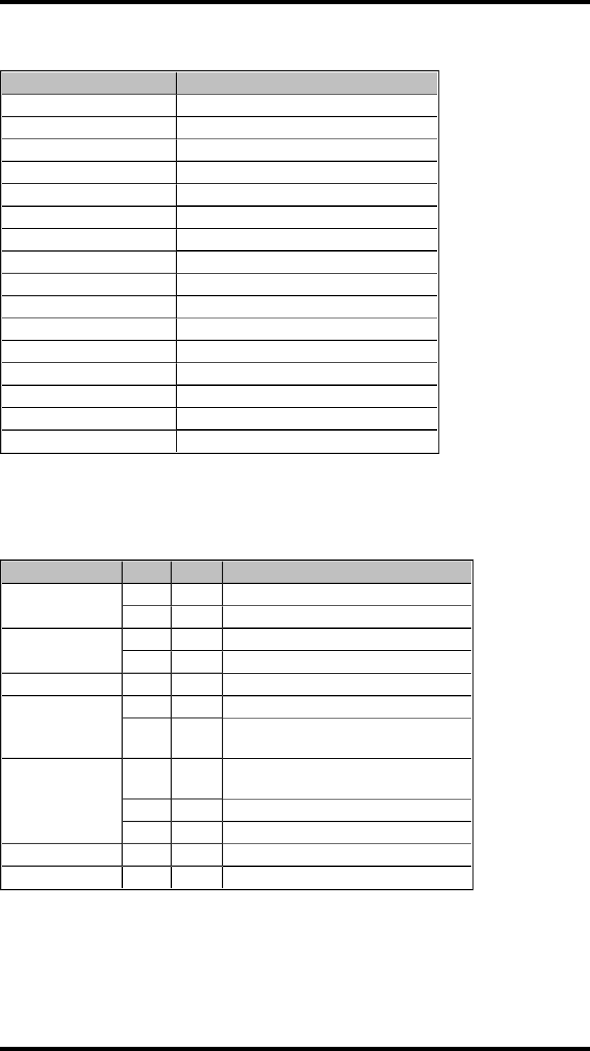
Function LEDs indication in operating mode
FUNCTIONLED OFF ON INDICATES
1X No transmitter is registered
X One or more transmitters are registered
2X No transmitter is logged in
X One transmitter is logged in
3 X Receiving correct RS485 data
4
X Settings in the safety CPUs conform to SIL3
X Settings in the safety CPUs do NOT con-
form to SIL3
5
X FLASHES: The receiver is frequency scan-
ning
X Automatic frequency control processing
X Automatic frequency control finetuned
6 X Receiving correct sync word
7 X Receiving correct radio packet
-8-
RECEIVER R00004-10 WITH A RELAY EXPANSION BOARD
WARNING! The receiver must NOT be opened by any other than a qualified installer. Make sure to
turn the electricity off before opening the receiver.
IMPORTANT! Tele Radio remote controls are often built into wider applications. We recommend
that the system is provided with a wired emergency stop where necessary.
Base board:
1. LED representing stop relays 1+2 (red) 8. Antenna connector
2. Stop relays 1+2 9. Function LEDs 1-4 (1= red, 2= yellow, 3=
green, 4= orange)
3. Obligatory fuse 2A (slow) 10. Function button (Cancel)
4. Terminal block for input power 11. Terminal block for mixed I/O
5. Function relays 1-7 12. Select button (OK)
6. Relay LEDs 1-7 (red) 13. Programming connector
7. Function LEDs 5-7 (5= red, 6= yellow, 7=
green) 14. Power LED (yellow)
-9-
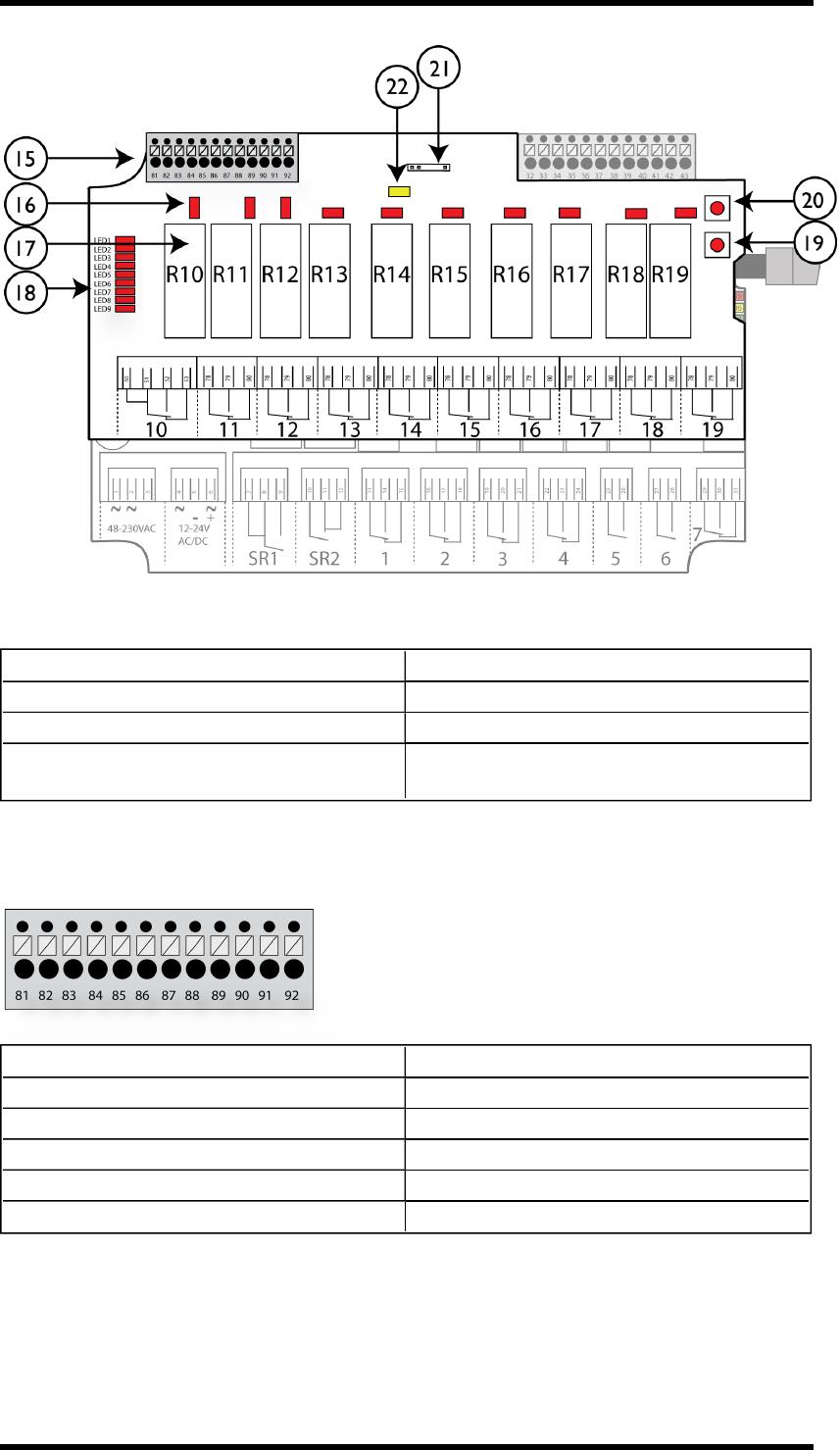
Expansion board:
15. Terminal block for digital inputs 19. Select button (OK)
16. Relay LEDs 10-19 20. Function button (Cancel)
17. Function relays 10-19 21. Programming connector
18. LEDs representing stop relays 1-2 and func-
tion relays 1-7 on the base board 22. Power LED (yellow)
Terminal block for digital inputs
81. GND 87. Digital input 5
82. GND 88. Digital input 6
83. GND 89. Digital input 7
84. GND 90. Digital input 8
85. Digital input 3 91. Digital input 9
86. Digital input 4 92. Digital input 10
-10 -
Current consumption
Input power Min.* Max.**
12V AC 0.06A -
24V AC 0.03A 0.3A
48V AC 0.02A 0.2A
115V AC 0.009A 0.07A
230V AC 0.008A 0.04A
12V DC 0.06A 0.6A
24V DC 0.03A 0.2A
* Minimum current consumption= Receiver powered, no radio session established, nothing else
activated on the receiver
** Maximum current consumption= All relays activated on the receiver
Technical data
R00004-10
Number of stop relays 2 (16A)
Number of function relays 17 (potential free*, 8A)
Digital inputs 10
Transistor output 1
Duplex communication Duplex or simplex communication possible
Max. number of transmitters 15
Operating frequency 2405-2480 MHz
Number of channels/ banks 16
Channel separation 5 MHz
IP class 66
Size 176 x 126 x 75 mm./ 6.9 x 5 x 2.9 in.
Weight 800 g./ 1.8 lbs
Radiotype Low IF topology
Sensitivity Better than -110 dBm
Antenna 1 external RPSMA antenna
Operating temperature -20- +55°C/ -4-+130°F
* potential free means that you have to supply voltage to get voltage out of a relay (e.g. via the included connection comb)
-11 -
Function LEDs indication in operating mode
FUNCTIONLED OFF ON INDICATES
1X No transmitter is registered
X One or more transmitters are registered
2X No transmitter is logged in
X One transmitter is logged in
3 X Receiving correct RS485 data
4
X Settings in the safety CPUs conform to SIL3
X Settings in the safety CPUs do NOT con-
form to SIL3
5
X FLASHES: The receiver is frequency scan-
ning
X Automatic frequency control processing
X Automatic frequency control finetuned
6 X Receiving correct sync word
7 X Receiving correct radio packet
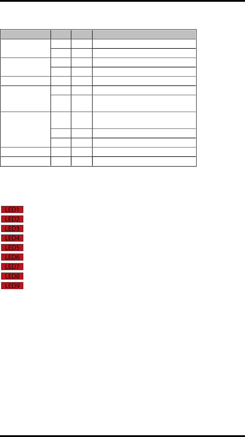
Base board relay LEDs
LED 1= function relay 1
LED 2= function relay 2
LED 3= function relay 3
LED 4= function relay 4
LED 5= function relay 5
LED 6= function relay 6
LED 7= function relay 7
LED 8= (not used)
LED 9= stop relays 1+2
These LEDs light when the corresponding stop and function relays on the base board are activated. See
list for corresponding base board relay.
-12 -
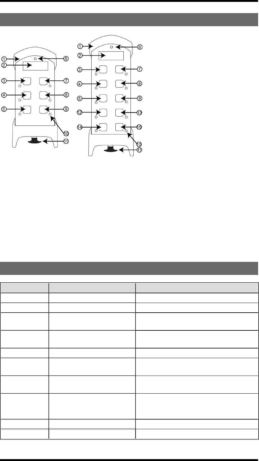
TRANSMITTERS T00009-22, T00011-24
1. Rubber cover 9. Button 6 (T00009-22: right start button)
2. Display 10. Button LEDs
3. Button 1 11. Stop button
4. Button 3 12. Button 7*
5. Button 5 (T00009-22 : left start button) 13. Button 8*
6. Top LED 14. Button 9 (left start button)*
7. Button 2 15. Button 10 (right start button)*
8. Button 4
*Only on T00011-24
TECHNICAL DATA
T00009-22 T00011-24
No. of buttons 6 x 2-step buttons 10 x 2-step buttons
On/off switch Yes No
Max. no of receiv-
ers 4 8
Size 160 x 76 x 37 mm./6.3 x 3 x 1.4
in. 210 x 76 x 37 mm./8.2 x 3 x 1.4 in.
Weight 295 g./ 0.6 lbs. 400 g./ 0.9 lbs.
No. of channels/
banks 16 16
Operating
frequency 2405-2480 MHz 2405-2480 MHz
Operating time
(with continuous
usage)
16 h. 16 h.
Antenna 1 internal PCB antenna 1 internal PCB antenna
Radio type Low IF topology Low IF topology
-13 -
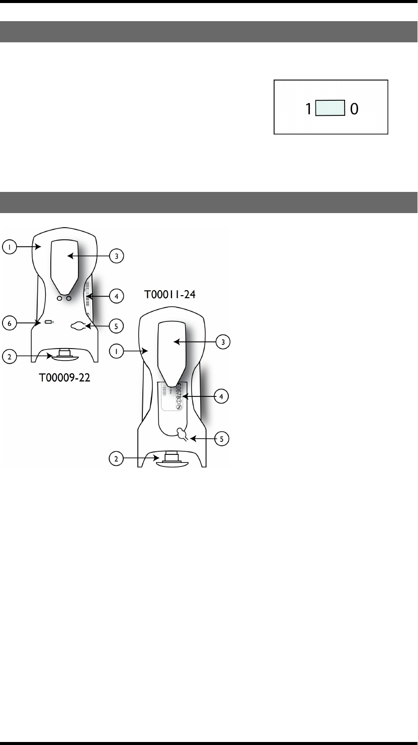
ON/OFF SWITCH
The T00009-22 transmitter has an on/off switch on the backside.
The on/off switch has 2 positions:
1= on
0= off
The on/off switch breaks the power supply from the battery.
When in position 0/off, the transmitter can not be started unless
you connect the charger plug.
TRANSMITTER BACKSIDE
1. Rubber cover 4. CE and product label
2. Stop button 5. Battery charger socket
3. Clip 6. On/off switch*
*only on T00009-22
-14 -
Chapter 4: FCC/ IC INFORMATION
CHAPTER 4: FCC/ IC INFORMATION
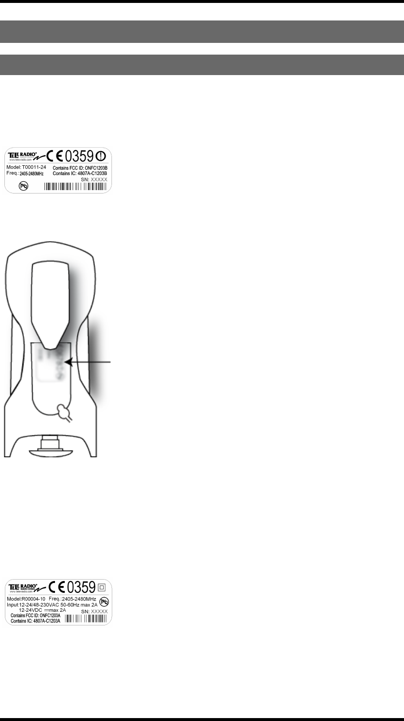
FCC/IC INFORMATION FOR THE T00011-24, R00004-10
Product label and placement on the transmitter
T00011-24
You will find the product label in the back of the transmitter (see picture below).
Product label and placement on the receiver
R00004-10
You will find the product label on the outside of the enclosure of the receiver.
-15 -
Chapter 4: FCC/ IC INFORMATION
FCC/IC label and placement on the transmitter
T00011-24
The FCC/ IC label is placed on the radio module. The radio module is mounted inside the transmitter.
L’étiquette FCC/IC est placée sur le module radio. Le module radio est monté à l’intérieur du récep-
teur.
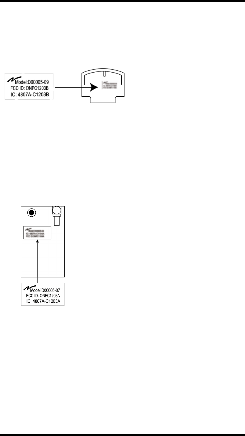
FCC/ IC label placement on the receiver
R00004-10
The FCC/ IC label is placed on the radio module. The radio module is mounted inside the receiver.
L’étiquette FCC/IC est placée sur le module radio. Le module radio est monté à l’intérieur de l’é-
metteur.
-16 -

Chapter 4: FCC/ IC INFORMATION
The radio module
Function
Each receiver and transmitter unit in the Tele Radio Tiger product range, contains a radio module that is
specifically designed to match a Tele Radio Tiger unit in terms of physical dimensions, connection
points, voltage levels, signal interface etc. To use the radio modules in non Tele Radio products is not
permitted.
The radio modules are designed to interface directly to the main board of the receiver/transmitter unit.
They are power supplied by the main board and the radio circuit operates strictly according to
instructions from a microprocessor on the main board. The radio circuit config-uration is stored in a
flash memory on the radio module.
A receiver/transmitter unit with a defective/no radio module will give an error message immediately
after power up, and it will not be
possible to start a radio session.
Cross reference
Cross reference of radio modules and corresponding products:
Tiger unit Radio module:
T00011-24 TR304
R00004-10 TR283
Installation
Installation instructions for TR304
1. Make sure that the transmitter unit is turned off.
2. Open the enclosure.
3. Assemble TR304 to the 2 x 12 pole socket connector on the bottom side of the main board.
Installation instructions for TR283
1. Make sure that the receiver unit is turned off.
2. Open the enclosure.
3. Connect the 2x12 pole socket connector of TR283 directly to the main board.
-
17
-
To satisfy FCC RF exposure requirements, a separation distance of 20 cm or more
should be maintained between the antenna of this device and persons during device
operation.
To ensure compliance, operations at closer than this distance is not recommended.
Les antennes installées doivent être situées de facon à ce que la population ne puisse
y être exposée à une distance de moin de 20 cm. Installer les antennes de facon à ce
que le personnel ne puisse approcher à 20 cm ou moins de la position centrale de l'
antenne.
La FCC des éltats-unis stipule que cet appareil doit être en tout temps éloigné d'au
moins 20 cm des personnes pendant son functionnement.
FCC statement
Statement for warning:

Chapter 4: FCC/ IC INFORMATION
Caution: The user is cautioned that changes or modifications not expressly approved by the party
responsible for compliance could void the user's authority to operate the equipment.
This device complies with Industry Canada licence-exempt RSS standard(s) and Part 15 of the FCC
Rules. Operation is subject to the following two conditions:
(1) this device may not cause harmful interference, and
(2) this device must accept any interference received, including interference that may cause undesired
operation.
Le présent appareil est conforme aux CNR d'Industrie Canada applicables aux appareils radio exempts
de licence et la partie 15 des Règles FCC. L'exploitation est autorisée aux deux conditions suivantes :
(1) l'appareil ne doit pas produire de brouillage, et
(2) l'utilisateur de l'appareil doit accepter tout brouillage radioélectrique subi, même si le brouillage est
susceptible d'en compromettre le fonctionnement.
Cet appareil est conforme aux limites d’exposition au rayonnement RF stipulées par la FCC et l’IC pour
une utilisation dans un environnement non contrôlé. L'utilisateur final doit suivre les instructions de
fonctionnement spécifiques pour le respect d'exposition aux RF. Lesémetteurs ne doivent pas être
placées près d’autres antennes ou émetteurs ou fonctionner avec ceux-ci.
Note: this equipment has been tested and found to comply with the limits for a class b digital device,
pursuant to part 15 of the FCC rules. These limits are designed to provide reasonable protection against
harmful interference in a residential installation. This equipment generates, uses and can radiate radio
frequency energy and, if not installed and used in accordance with the instructions, may cause harmful
interference to radio communications. However, there is no guarantee that interference will not occur
in a particular installation. If this equipment does cause harmful interference to radio or television
reception, which can be determined by turning the equipment off and on, the user is encouraged to try
to correct the interference by one or more of the following measures:
—reorient or relocate the receiving antenna.
—increase the separation between the equipment and receiver.
—connect the equipment into an outlet on a circuit different from that to which the receiver is
connected.
—consult the dealer or an experienced radio/TV technician for help.
The radio module in this product is labelled with its own FCC ID and IC number. The FCC ID and IC is
not visible when the radio module is installed inside another device. Therefore, the outside of the device
into which the module is installed must also display a label referring to the radio module. The final end
device must be labelled in a visible area with the following:
“Contains FCC ID: ONFC1203A”
“Contains IC: 4807A-C1203A”
or “Contains FCC ID: ONFC1203B”
“Contains IC: 4807A-C1203B”
-18 -
This radio transmitter (D00005-07) has been approved by Industry Canada to operate with the antenna types
listed below with the maximum permissible gain and required antenna impedance for
each antenna type indicated. Antenna types not included in this list, having a gain
greater than the maximum gain indicated for that type, are strictly prohibited for use
with this device.
Gain of antenna: 3.0dBi max.
Type of antenna: 50ohm, Omni-directional
Le présent émetteur radio (D00005-07) a été approuvé par Industrie Canada pour
fonctionner avec les types d'antenne énumérés ci-dessous et ayant un gain admissible
maximal et l'impédance requise pour chaque type d'antenne.
Les types d'antenne non inclus dans cette liste, ou dont le gain est supérieur au gain
maximal indiqué, sont strictement interdits pour l'exploitation de l'émetteur.
Gain d'antenne: 3.0dBi maximal
Type d'antenne: 50 ohm, Omni-directionnel
Under Industry Canada regulations, this radio transmitter may only operate using an
antenna of a type and maximum (or lesser) gain approved for the transmitter by
Industry Canada. To reduce potential radio interference to other users, the antenna
type and its gain should be so chosen that the equivalent isotropically radiated power
(e.i.r.p.) is not more than that necessary for successful communication.
Conformément à la réglementation d'Industrie Canada, le présent émetteur radio peut
fonctionner avec une antenne d'un type et d'un gain maximal (ou inférieur) approuvé
pour l'émetteur par Industrie Canada. Dans le but de réduire les risques de
brouillage radioélectrique à l'intention des autres utilisateurs, il faut choisir le type
d'antenne et son gain de sorte que la puissance isotrope rayonnée équivalente
(p.i.r.e.) ne dépasse pas l'intensité nécessaire à l'établissement d'une communication
satisfaisante.
Chapter 5: INSTALLERS GUIDE
CHAPTER 5: INSTALLERS GUIDE
CREATE PIN CODES
NOTE! You can store up to 10 PIN codes in the transmitter.
NOTE! '0000' is not a valid PIN code.
1. Make sure that the stop button is pressed.
2. Pull out the stop button.
The top LED lights (green when the battery capacity is good, red when the battery capacity is poor).
3. Press the right start button. Keep pressed.
4. Press the stop button.
5. Release the right start button.
The top LED flashes (green when the battery capacity is good, red when the battery capacity is poor)
when in menu mode.
6. Go to [Enter PIN].
7. Select what position in the list that you want to store the new PIN code in by pressing the left start
button.
8. Enter the new PIN code (4 digits) by pressing the buttons 1-4:
PRESS BUTTON TO
1 step up
2 step down
3 step right
4 step left
9. Confirm by pressing the left start button.
ERASE PIN CODE
1. Make sure that the stop button is pressed.
2. Pull out the stop button.The LEDs light (green when the battery capacity is good, red when the
battery capacity is poor).
3. Press the right start button. Keep pressed.
4. Press the stop button.
5. Release the right start button.
The LEDs light (green when the battery capacity is good, red when the battery capacity is poor) when in
menu mode.
6. Go to [Erase PIN].
-19 -

Chapter 5: INSTALLERS GUIDE
7. Scroll the list to select the PIN code that you want to erase.
MOVEJOYSTICK TO
up step up
down step down
8. Select by pressing the left start button.
9. Confirm by pressing the left start buttons.
SHOW REGISTERED PIN CODES
1. Make sure that the stop button is pressed.
2. Pull out the stop button.
The top LED lights (green when the battery capacity is good, red when the battery capacity is poor).
3. Press the right start button. Keep pressed.
4. Press the stop button.
5. Release the right start button.
The top LED flashes (green when the battery capacity is good, red when the battery capacity is poor)
when in menu mode.
6. Go to [Show PIN].
7. The display shows a list of all registered PIN codes.
START THE TRANSMITTER IN OPERATING MODE
1. Make sure that the stop button is pressed
2. Pull out the stop button.
The top LED lights (green when the battery capacity is good, red when the battery capacity is poor).
3. If PIN codes are used for authorization: Go to the next section.
4. WITHIN 3 MINUTES FROM PULLING OUTTHESTOPBUTTON:
Press a button to select the receiver(s) that you want to operate.
The receiver(s) that was selected in the last session will be automatically selected, which is indicated by
the corresponding LED(s) that light red. If no receiver(s) has been selected, the LEDs for all available
receivers will flash red. If a receiver is selected, the LEDs next to the left and the right start buttons flash
red. If no receiver(s) are selected, only the LED next to the right start button flashes red.
5. Press both start buttons at the same time.
The buzzer beeps.
6. Release the start buttons.
The buzzer stops beeping. The top LED flashes (green when the battery capacity is good, red when the
battery capacity is poor).
-20 -

Chapter 5: INSTALLERS GUIDE
7. When radio communication has been established, the top LED lights (green when the battery
capacity is good, red when the battery capacity is poor).
If radio communication is not established within 25 seconds, the transmitter turns off.
START THE TRANSMITTER IN OPERATING MODE WITH A PIN
CODE
1. Make sure that the stop button is pressed.
2. Pull out the stop button.
The top LED lights (green when the battery capacity is good, red when the battery capacity is poor).
3. WITHIN 3 MINUTES : Enter the PIN code (4 digits) by pressing the buttons according to the table.
FORDIGIT: 1 2 3 4 5 6 7 8 9 0
T00009-22, PRESSBUTTON: 1 2 3 4 - - - - - -
T00011-24, PRESSBUTTON: 1 2 3 4 5 6 7 8 - -
4. WITHIN 3 MINUTES FROM PULLING OUTTHESTOPBUTTON:
Press a button to select the receiver(s) that you want to operate.
The receiver(s) that was selected in the last session will be automatically selected, which is indicated by
the corresponding LED(s) that light red. If no receiver(s) has been selected, the LEDs for all available
receivers will flash red. If a receiver is selected, the LEDs next to the left and the right start buttons flash
red. If no receiver(s) are selected, only the LED next to the right start button flashes red.
5. Press both start buttons at the same time.
The buzzer beeps.
6. Release the start buttons.
The buzzer stops beeping. The top LED flashes (green when the battery capacity is good, red when the
battery capacity is poor).
7. When radio communication has been established, the top LED lights (green when the battery
capacity is good, red when the battery capacity is poor).
If radio communication is not established within 25 seconds, the transmitter turns off.
-21 -
NAVIGATE IN MENU MODE
To navigate when in menu mode, press:
Button 1 Step down
Button 2 Step up
Button 3 Step left/ go back
Button 4 Step right
The left start button Select/ confirm
The right start button Exit
LOGIN/LOGOUT
Quick logout
NOTE! When the transmitter has established radio communication with one or more receivers, you
can make a Quick logout from those receivers. Note that the Quick logout will log the transmitter out
from all receivers that are participating in the session.
NOTE! If you need to log out a transmitter that is lost or damaged, it is possible to log out from the
receiver. We do not recommend this way of logging out. Contact your representative for assistance.
NOTE! To be able to control a receiver, the transmitter must be registered in the receiver, and logged
in to the receiver. If another transmitter is already logged in to the receiver, it has to be logged out
before any other transmitter can be logged in. If no transmitter is logged in to a receiver, a registered
transmitter will automatically log in when sending radio signals to the receiver. The transmitter will stay
logged in until it is manually logged out. More than one transmitter can be registered in the receiver, but
only one transmitter can be logged in at a time.
1. Make sure that the transmitter is started in operating mode.
NOTE! The transmitter must have established a radio session with one or more receivers.
2. Press the left start button. Keep pressed.
3. Press the stop button.
4. Release the left start button.
The top LED lights red.
The display shows [Logging out].
The transmitter turns off after logging out.
LOGOUT FROM MENU MODE
1. Make sure that the stop button is pressed.
2. Pull out the stop button.
The top LED lights (green when the battery capacity is good, red when the battery capacity is poor).
3. Press the right start button. Keep pressed.
-22 -

4. Press the stop button.
5. Release the right start button.
The top LED flashes (green when the battery capacity is good, red when the battery capacity is poor)
when in menu mode.
6. Go to [Logout].
7. Select by pressing the left start button.
8. Select a receiver to log out from.
9. Confirm by pressing the left start button.
The display shows [Logging out...] while the process is ongoing.
If logout fails, the display shows [FAILED]. The transmitter turns off.
If logout succeeds, the display shows [OK]. The transmitter turns off after logging out.
TURN THE TRANSMITTER OFF
1. Press the stop button.
The transmitter turns off. All relays deactivate.
REGISTER
IMPORTANT! Do not perform this when the receiver is in a session with another transmitter. The
radio communication may become disturbed or broken.
NOTE! Before starting to perform these settings, make sure that the stop relays are deactivated!
Register the transmitter in the receiver
1. Press the receiver Function button.
Function LED 1 flashes red.
2. Relay LEDs 1-7 light to show how many transmitters that are already registered in the receiver (see
table).
3. Press the receiver Select button for less than 4 seconds to enter registering mode on the receiver.
The receiver will stay in registering mode for 1 minute or until a transmitter has been registered.
4. On the transmitter: Make sure that the stop button is pressed.
5. Pull out the stop button.
The top LED lights (green when the battery capacity is good, red when the battery capacity is poor).
6. Press the right start button. Keep pressed.
7. Press the stop button.
8. Release the right start button.
-23 -
The top LED flashes (green when the battery capacity is good, red when the battery capacity is poor)
when in menu mode.
9. Go to [Register].
10. Select by pressing the left start button.
11. Select a receiver. Confirm by pressing the left start button. The display shows [Registering] while the
process is ongoing.
12. When the receiver has found the transmitter, all relay LEDs flash. Press the receiver Select button.
Function LEDs 1-7 flash 3 times. The relay LEDs go off.
13. All Function LEDs light for approx. 1 second.
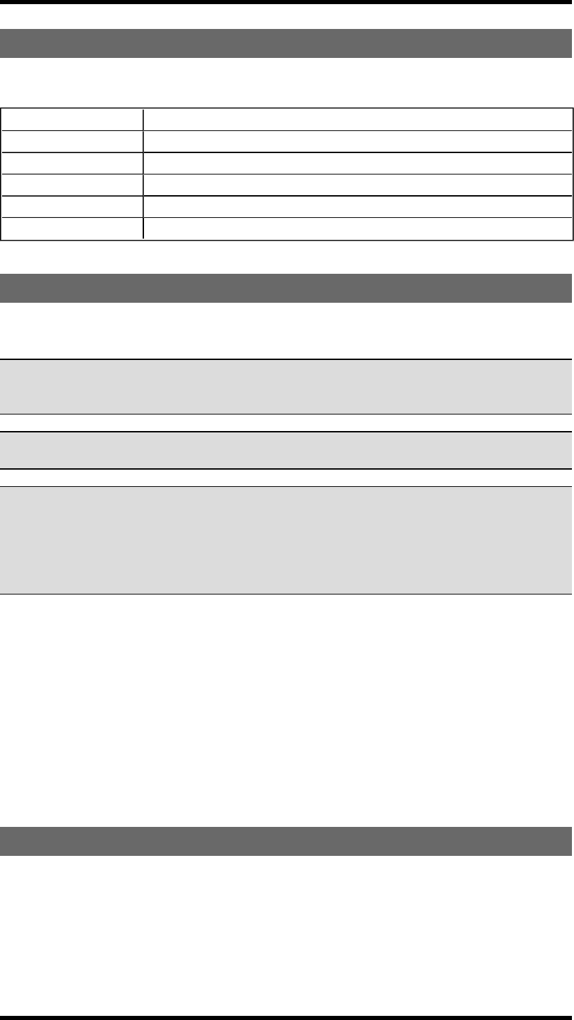
Number of transmitters registered in the receiver
RELAY LED NO. STATUS NO. OF TRANSMITTERS
1 ON 1
2 ON 2
3 ON 3
4 ON 4
5 ON 5
6 ON 6
7 ON 7 or more
Example: Relay LED 2 lights, which means that 2 transmitters are currently registered in the receiver.
ERASE
Erase a transmitter from the receiver
NOTE! If a transmitter is lost or becomes seriously damaged, it is possible to erase it from the receiver.
We do not recommend this way. Contact your representative for assistance.
NOTE! If the transmitter already have receivers registered, we recommend that you erase all receivers
from the transmitter before starting the replacement. The receiver will automatically be stored in the
same position as it was stored in the old transmitter. If this position is not available, the replacement will
not take place.
1. Make sure that the stop button is pressed.
2. Pull out the stop button.
The top LED lights (green when the battery capacity is good, red when the battery capacity is poor).
3. Press the right start button. Keep pressed.
4. Press the stop button.
5. Release the right start button.
The top LED flashes (green when the battery capacity is good, red when the battery capacity is poor)
when in menu mode.
-24 -
6. Go to [Erase].
7. Select by pressing the left start button .
8. Select a receiver. Confirm by pressing the left start button. The display shows [Erasing] while the
process is ongoing.
If the erasing fails, the display shows [FAILED]. The transmitter turns off.
If the erasing succeeds, the display shows [OK]. The transmitter turns off.
REPLACE
You can replace a registered transmitter with another transmitter without having access to the receiver.
IMPORTANT! If the transmitter that needs to be replaced is registered in more than one receiver, it will
only be replaced in one receiver at a time. If you want to replace a transmitter in more than one
receiver, you need to perform a replacement for each receiver.
IMPORTANT! Do not perform this when the receiver is in a session with another transmitter. The
radio communication may become disturbed or broken.
NOTE! If the transmitter already have receivers registered, we recommend that you erase all receivers
from the transmitter before starting the replacement. The receiver will automatically be stored in the
same position as it was stored in the old transmitter. If this position is not available, the replacement will
not take place.
Replace a transmitter with a new transmitter
1. Make sure that the stop button is pressed.
2. Pull out the stop button.
The top LED lights (green when the battery capacity is good, red when the battery capacity is poor).
3. Press the right start button. Keep pressed.
4. Press the stop button.
5. Release the right start button.
The top LED flashes (green when the battery capacity is good, red when the battery capacity is poor)
when in menu mode.
6. Go to [Replace]. Select by pressing the left start button.
7. Enter the serial number/ID code for the transmitter that you want to replace by pressing the buttons
according to the table below:
PRESS BUTTON TO
1 count -1
2 count +1
3 go left
4 go right
-25 -

8.Press the left start button.
The display shows [Replacing] while the process is ongoing.
If the replacement fails, the display shows [FAILED].The transmitter turns off.
If the replacement succeeds, the display shows [OK]. The transmitter turns off.
AUTOMATIC SHUTDOWN
Turning on automatic shutdown can save battery capacity by automatically turning the transmitter off
when no function has been activated for a set time.
Set the time for automatic shutdown
1. Start the transmitter.
2. Enter menu mode.
3. Go to [Auto Shutdown]. Select by pressing the left start button.
4. Select the time that you want for automatic shutdown: 0-255 minutes. If you want to turn off
automatic shutdown, select 0. Confirm by pressing the left start button.
FREQUENCIES & CHANNELS
NOTE! The receiver will automatically detect and switch to the same channel that the transmitter is
using.
Switch channel on the transmitter
1. Make sure that the stop button is pressed.
2. Pull out the stop button.
The top LED lights (green when the battery capacity is good, red when the battery capacity is poor).
3. Press the right start button. Keep pressed.
4. Press the stop button.
5. Release the right start button.
The top LED flashes (green when the battery capacity is good, red when the battery capacity is poor)
when in menu mode.
6. Go to [Channel/Bank].
7. Go to the frequency table and select a channel. Confirm by pressing the left start button.
-26 -
FREQUENCY BAND 2.4 GHZ
CHANNEL FREQUENCY
11 2405
12 2410
13 2415
14 2420
15 2425
16 2430
17 2435
18 2440
19 2445
20 2450
21 2455
22 2460
23 2465
24 2470
25 2475
26 2480
RELAY FUNCTIONALITY
NOTE! If Operating mode 0 is selected, you can not make these settings. Contact your representative
for assistance.
NOTE! Momentary relay functionality is default. That means that the relay will only be activated when
you press a button on the transmitter. When the button is released, the relay deactivates. Setting a relay
to latching means that the relay gets activated every time that you press a button, but in this case the
relay remains active until the button is pressed again.
NOTE! Before starting to perform these settings, make sure that the stop relays are deactivated!
NOTE! The settings options depend on the selected Operating mode.
Momentary and latching relay functionality
1. Press the receiver Function button 5 times. Function LED 5 flashes red.
2. Relay LEDs 1-19 light when the corresponding relay has a latching functionality:
Relay LED OFF= momentary relay functionality.
Relay LED ON= latching relay functionality
3. Press the receiver Select button to switch relay functionality.
4. The relay LED for the first relay available flashes. If that relay is momentary, function LED 5 is off. If
that relay is latching, function LED 5 lights.
5. Press the receiver Function button if you want to switch functionality. The status of function LED 5
changes.
-27 -
6. Press the receiver Select button to step to the next available relay. When you have stepped through
all the available relays, the receiver exits the LED menu and restarts.
Interlocking
What function relays that are available for interlocking, i.e. that can be blocked or prioritized when
pressed at the same time, depends on what Operating mode that is selected in the receiver. The relays
that have a direction function have automatic interlocking between opposite directions, e.g. up and
down. The relays that have a button function can be interlocked. Interlocking between relays is made in
the PC program Settings manager.
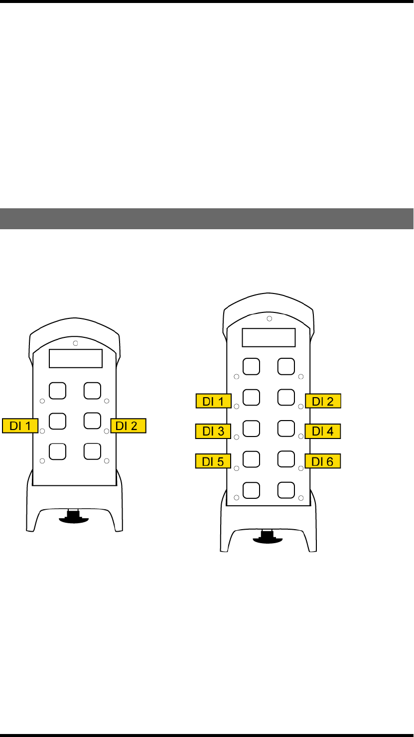
DIGITAL INPUTS
The digital inputs on the receiver are connected to the transmitter LEDs. If you need to make other
settings for the digital inputs indications on the transmitter, please contact your representative for
assistance.
-28 -
Chapter 6: BATTERY GUIDE
CHAPTER 6: BATTERY GUIDE
BATTERY PRECAUTIONS
Observe the following general battery warnings:
n As batteries contains flammable substances such as lithium or other organic solvents, they may
cause heating, rupture or ignition.
n Risk of explosion if battery is replaced with a battery of an incorrect type.
n Do not short circuit, disassemble, deform or heat batteries.
n Never try to charge a visibly damaged or frozen battery.
n Keep batteries out of reach of small children. Should a child swallow a battery, consult a phy-
sician immediately.
n Avoid direct soldering to batteries.
n When discarding batteries, insulate the + and - terminals of batteries with insulating/ masking
tape. Do not put multiple batteries in the same plastic bag.
n When improperly disposed, lithium batteries may short circuit, causing them to become hot,
burst or ignite.
n Store in a cool location. Keep batteries away from direct sunlight, high temperature, and high
humidity.
n Do not throw batteries into fire.
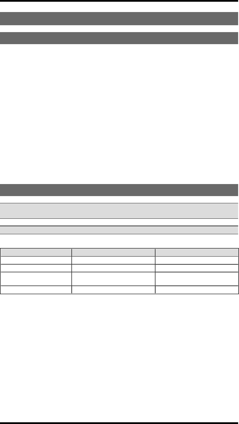
BATTERY INFORMATION
IMPORTANT! Electronics and batteries must be physically separated before disposal. Make sure that
electronics or batteries are not thrown in the household waste.
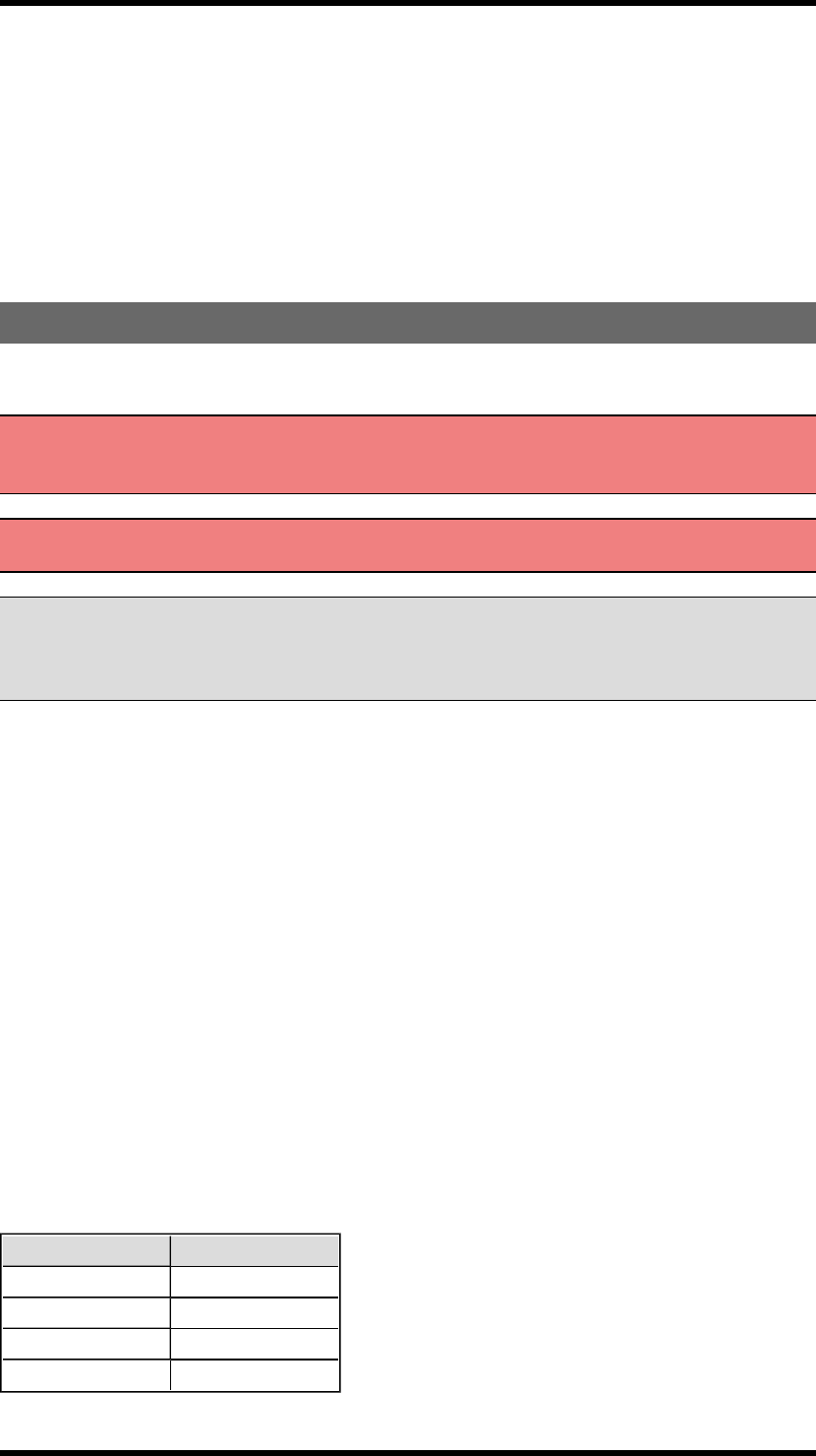
IMPORTANT! For transmitters with an on/off switch, the switch must be in on position when charging.
T00009-22 T00011-24
Battery type Internal, rechargeable lithium-ion battery External, rechargeable lithium-ion battery
Operating time Approx. 16 h. with continuous usage Approx. 16 h. with continuous usage
Charge Charger plug in the back of the transmitter Charger plug in the back of the transmitter
or in the Tele Radio 5 V DC charger unit
Charging temperature 0- 45°C/ 32-113 °F 0- 45°C/ 32-113 °F
-29 -
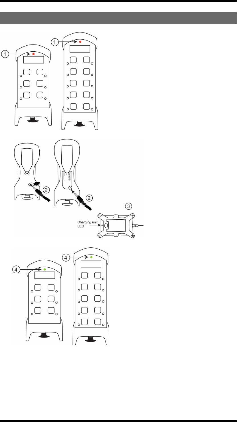
CHARGE THE BATTERY
1.When approx. 10% of the battery capacity
remains, the top LED lights red and the internal
buzzer beeps 3 times.
2. Put the charger plug into the socket in the back of
the transmitter. While charging, the top LED flashes
red.
3.The external battery can also be charged in a Tele
Radio AB charger unit .
4. When fully charged, the top LED lights
green.
-30 -

NOTE! For lithium-ion batteries, overcharging is not a problem. Lithium-ion batteries do not need to be fully discharged before being
recharged. Charging the battery before fully discharged will not cause premature loss of function. Lithium-ion batteries are designed
for operating environments from 0ºC to 60ºC/ 32ºF to 140ºF. Note that the environmental temperature and the operating
temperature are not necessarily the same. The higher the temperatures, the faster the discharge. When you do not intend to use the
transmitter for a longer period of time, we recommend that you remove the battery from the transmitter. The transmitter uses
current even when being turned off. Leaving the battery in the transmitter may affect the battery life span. Improper long term
storage of lithium-ion batteries can reduce their effective life. New lithium-ion batteries should be stored in a location with ambient
temperatures between 20ºC to 38ºC/ 70º to 100ºF at a 40% state of charge or lower. After use, batteries can be stored at higher
charge levels. After a longer period of storage, we recommend recharging of batteries prior to being placed back into service or use.
Batteries stored in cold environments may need to be stabilized within normal temperature ranges prior to recharging and use.
Batteries can be replaced when they are no longer capable of holding 80% of their original capacity. Users should consider how
frequently an old battery is recharged compared to when it was new. We recommend that you check with your representative if
you need further details.
REMOVAL OF INTERNAL BATTERY
IMPORTANT! Electronics and batteries must be physically separated before disposal. Make sure that
electronics or batteries are not thrown in the household waste.
1. Remove the clip. Remove the rubber cover by hand. Use a screwdriver to unscrew the 2 screws.
2. Use a screwdriver to unscrew the 4 screws. Remove the front encapsulation by hand. Turn the
transmitter around, so that the buttons face up.
3. Use a screwdriver to unscrew the screw in the middle of the transmitter. Lift the circuit board up by
hand.
4. The battery pack is placed behind the circuit board. Remove the battery by hand.
ROHS AND WEEE
In accordance with Directive 2002/95/EC on restriction of the use of certain hazardous substances in
electrical and electronic equipment (RoHS) and Directive 2002/96/EC on waste electrical and
electronic equipment (WEEE), Tele Radio AB strives to minimize the use of hazardous materials,
promotes reuse and recycling, and reduces emissions to air, soil and water. When a commercially viable
alternative is available, Tele Radio AB strives to restrict or eliminate substances and materials that pose
an environmental, health or safety risk.
-31 -

GUARANTEE, SERVICE, REPAIRS AND MAINTENANCE
The Tele Radio AB products are covered by a guarantee/warranty against material, construction and
manufacturing faults. During the guarantee/warranty period, Tele Radio AB may replace the product or
faulty parts. Work under guarantee/warranty must be carried out by Tele Radio AB or by an authorized
service centre specified by Tele Radio AB.
This is not covered by the guarantee/ warranty:
n Faults resulting from normal wear and tear
n Parts of a consumable nature
n Products that have been subject to unauthorized modifications
n Faults resulting from incorrect installation and use
n Damp and water damage
Maintenance:
n Repairs and maintenance must be carried out by qualified personnel
n Use spare parts from Tele Radio AB only
n Contact your representative if you require service or other assistance
n Keep the product in a dry, clean place
n Keep contacts and antennas clean
n Wipe off dust using a slightly damp, clean cloth
IMPORTANT! Never use cleaning solutions or high-pressure water.
-32 -