Tele Radio T60TX-0XSTL T60 MIDI TRANSMITTER User Manual IM T60 001 A5 US FCC OK1 indd
Tele Radio AB T60 MIDI TRANSMITTER IM T60 001 A5 US FCC OK1 indd
USERS MANUAL

DK
SE
NL
ES
FRDE
GB
US NO
176
CONTENTS / AMERICAN
176 Important Information
177 Codes
177 Placement of the Aerial and Receiver
178 The Transmitter
181 The Receiver
191 Supplement for the 460 system
193 Service and Support
194 Trouble Shooting Chart
195 Terms and conditions of sale
199 FCC Statements
200 Coding Tables 1-10, Appendix A
201 Coding Tables 0-15, Appendix B
202 Coding Tables
460-93, Appendix C
207
Connecting the receiver – see Appendix D
IMPORTANT!
In order to make optimal use of your system, it is important that
you take the time to read through this manual before you begin
to install/program your equipment.
GENERAL INFORMATION
The system works at the frequency 433.92MHz and uses frequency
modulation, commonly referred to as FM. The main benefi t of using FM
instead of the more common AM (amplitude modulation) is that FM is less
sensitive to the electrical interference generated by computers, electric
motors, etc.
Objects positioned between the transmitter and receiver aerial, especially
large metal objects (think about the reinforcement rods in concrete walls),
can affect the range in a very unpredictable manner, depending on how the
radio signals spread.
The effect of other radio transmitters operating on the same frequency
in the vicinity also affects the range. Due to these factors, it is diffi cult to
provide any general advice other than that if there is a free line of visibility
between the transmitter and the receiver the range with an optimal signal
should be the best.
The normal range for the transmitter in an interference-free environment
is about 50-100m.

SE
NLES
FR
DE
GB
US NO DK
177
T60 CODES
The transmitter and receiver that are to be used together must be coded
together before use. The T60 system has two different types of codes.
Adjustable codes:
All transmitters are equipped with a code switch that consists of 10 three-
position switches, which makes it possible to choose freely among 59,049
different codes.
Fixed individual code:
Each transmitter is supplied with a fi xed individual code that cannot be
changed.
“Learning” the codes:
In the T60 system, the transmitter and receiver are coded together
through a self-instruction process, in other words, the receiver “learns” the
transmitter’s code. You can have the receiver learn only the adjustable code
or both the adjustable and fi xed individual code.
Compatible with the 460 system
The T60 system is compatible with Tele Radio’s 460 system.
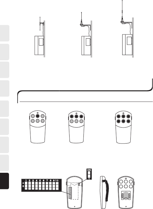
PLACEMENT OF THE AERIAL AND RECEIVER
The receiver should be placed:
-As far as is possible, protected from the elements.
-With cable holders facedown.
Placement of the receiver aerial
-Place the aerial high above the ground.
-The aerial should not be in the vicinity of metal objects such as electrical cables
and other aerials.
The normal range for the transmitter in an interference-free environment
is about 50-100m.
DK
SE
NL
ES
FRDE
GB
US NO
178
DIP-433K3
1/4-433Kx
5/8-433Kx
X= 3, 5, or 10m aerial cable
+
0
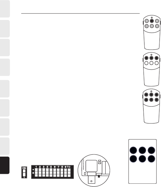
HANDHELD TRANSMITTER MINI
Dimensions:
84x40x16mm
T60TX-01SHL
with 1 button function
T60TX-03SHL
with 3 button functions
T60TX-06SHL
with 6 button functions
Battery 3V
123
456
1 2 3
+
4
123 56789 1
0
+
0
(B)
ON
1
(A)
System switch
Code switch
T60TX-0XSHL
SE
NLES
FR
DE
GB
US NO DK
179
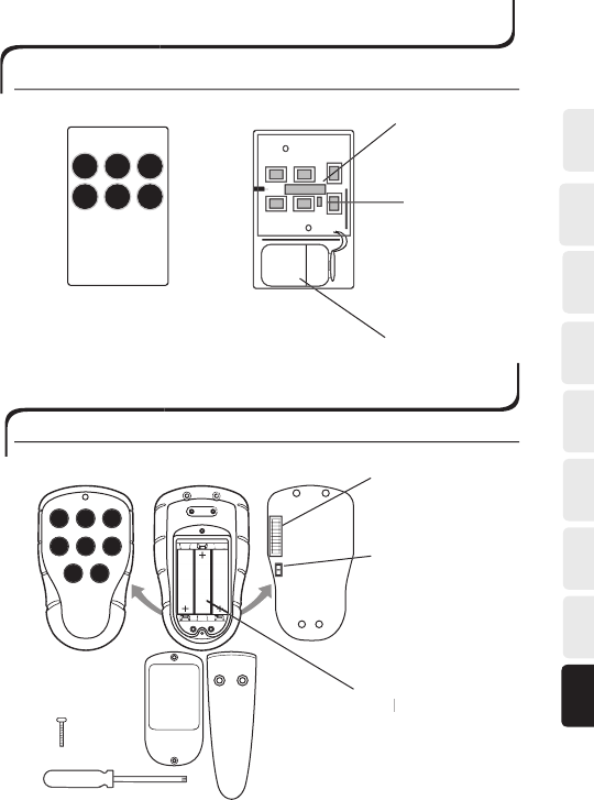
Dimensions: 98x62x22mm
(A)
(B)
System switch
Code switch
Battery 9V
HANDHELD TRANSMITTER MIDI
(A)
(A)
(B)
Battery
1,5V, AAA
Battery 1,5V, AAABattery
+
+
87
1
4
23
56
8x
ON
1
T60TX-08STL
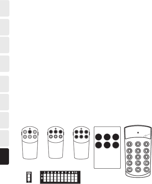
HANDHELD TRANSMITTER MIDI-T
T60TX-0XSTL
Code switch
System switch
T60TX-0XSTL
DK
SE
NL
ES
FRDE
GB
US NO
180
System switch*
*Note: During adjustment, the transmitter must be turned off.
(B)
(A)
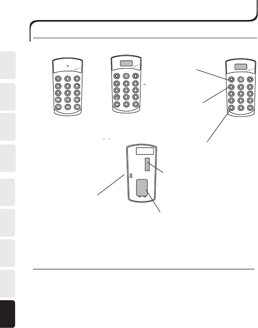
MOBILE TRANSMITTER MAXI
Transmitter T60TX-15SML
with 15 button functions
Dimensions:
143x62x38mm
Function buttons
Battery 9V
Port no. buttons
Shortcuts for functions
Shortcuts for functions
T60TX-15DML
Code switch
SHORTCUT FOR ONE FUNCTION (T60TX-15DML)
The * and # buttons are used to program a shortcut (1 selection per but-
ton) for a specifi c function.
To program a shortcut set the port you wish
to save, press * or # for more than 3 seconds (the display fl ashes). The
port has now been saved as a shortcut. To reach the shortcut, press the
appropriate button once.
T60TX-15SML/T60TX-15DML T60RX-0XYSL
SE
NLES
FR
DE
GB
US NO DK
181
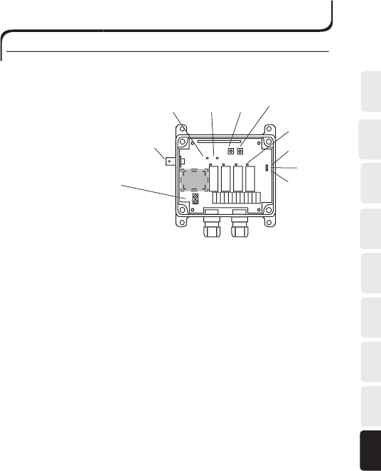
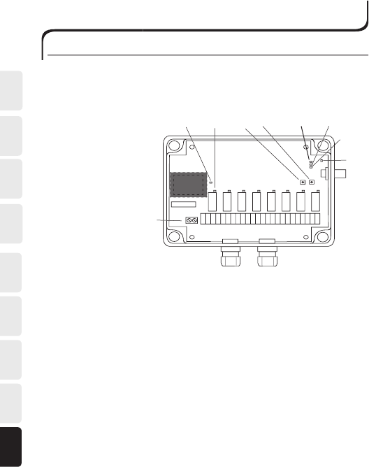
T60RX-0XYSL
Operating voltage: 12-28V AC/DC or 48/115/230V AC
Dimensions: 132x133x45mm
Enclosure: IP 65
4
RECEIVER
4
1
2
3
5
6
7
8
9
10
*
1 2 3 4 5 6 7 8 9 10 11 12
Note: Connecting the recei-
ver – see Appendix D
1. Yellow LED. Lights when the receiver has the correct supply voltage.
2. Green LED. Lights when the receiver receives a radio signal.
3. Function button.
4. Select button.
5. Red LED. Each relay is fi tted with an LED that lights when the
relay switches.
6. Red LED.
6.1. Lights. -Code learning enabled.
6.2. Flashes. - Adjustable code learnt (1-10).
6.3. Flashes twice. - One or more fi xed individual codes have been learnt.
7. Yellow LED. Flashes when one of the relays has a latching function.
8. Green LED. Flashes when one of the relays is interlocked.
9. Connection terminal for the supply voltage.
10. BNC contact for the aerial.
DK
SE
NL
ES
FRDE
GB
US NO
182
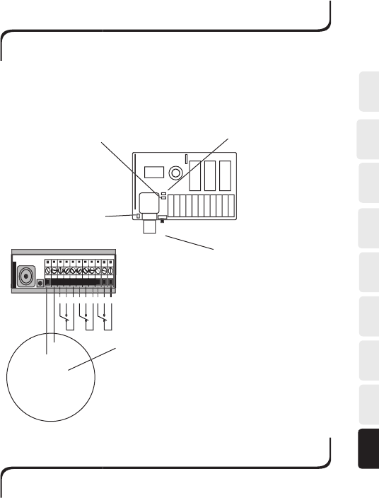
T60RX-0XYSL
Operating voltage: 12-28V AC/DC or 48/115/230V AC
Dimensions: 175x125x45mm
Enclosure: IP 65
ROBUST RECEIVER
2
3
4
5
8
9
10
Note: Connecting the
receiver – see Appendix D
* TRAFO
1
6
7
1. Yellow LED. Lights when the receiver has the correct supply voltage.
2. Green LED. Lights when the receiver receives a radio signal.
3. Function button.
4. Select button.
5. Red LED. Each relay is fi tted with an LED that lights when the
relay switches.
6. Red LED.
6.1. Lights. - Code learning enabled.
6.2. Flashes. - Adjustable code learnt (1-10).
6.3. Flashes twice. - One or more fi xed individual codes have been learnt.
7. Yellow LED. Flashes when one of the relays has a latching function.
8. Green LED. Flashes when one of the relays is interlocked.
9. Connection terminal for the supply voltage.
10. BNC contact for aerial.

SE
NLES
FR
DE
GB
US NO DK
183
T60RX-0XYSL
PROGRAMMING RECEIVERS T60RX-0XYSL
The function and select buttons on the receiver are used to program it.
The
function button is used to step
through the different program alternatives. The select button is used to
confirm program alternative selections.
Initially, it is possible to step through the following alternatives by pressing
the function button.
RED LED (no. 6) - Learn a transmitter’s code
YELLOW LED (no. 7) - Set the momentary/latched relay function
GREEN LED (no. 8) - Set the interlock function
When one of the above program alternatives has been selected using the
select button, the function button is used to step through which relay or
relays are to be programmed. The red LEDs above the relays indicate which
relay or relays are selected. See further under the appropriate programming
sequence.
LEARNING THE TRANSMITTER’S CODE
Adjustable code
Ensure that the desired adjustable code is set on the transmitter’s code
switch.
1. Use the function button to select the “learn code” program alternative
(RED LED).
2. Confi rm the selection with the select button. The red LEDs above the
relays light.
3.Using the function button, it is possible to step through to the relay or
relays to be coded.
- If a single relay is selected, it will be controlled by the transmitter
button used during the learning process.
- If all relays are selected, the system will exhibit normal functionality.
That is, the transmitter’s fi rst button is to control relay 1, button 2 is to
control relay 2, and so on.
4. Confi rm that the adjustable code is to be learnt by pressing the select
button once.

DK
SE
NL
ES
FRDE
GB
US NO
184
5. Program the transmitter’s code by holding down the desired transmitter
button until red LED no. 6 fl ashes three times.
Red LED (no. 6) flashes to indicate that the transmitter’s adjustable code has
been stored.
Adjustable code and fi xed individual code
1. Use the function button to select the “learn code” program alternative
(RED LED).
2. Confi rm the selection with the select button. The red LEDs above the
relays light.
3. Using the function button, it is possible to step through to the relay or
relays to be coded.
- If a single relay is selected, it will be controlled by the transmitter
button used during the learning process.
- If all relays are selected, the system will exhibit normal functionality.
That is, the transmitter’s fi rst button is to control relay 1, button 2 is to
control relay 2, and so on.
4. Confi rm that an adjustable code and fi xed individual code are to be
learnt in the following manner:
- Press the select button and release it after 0.3 - 4 seconds.
- Press the select button again within 1 second and hold it down for at
least 1 second.
5. Learn the transmitter’s code by holding down the desired transmitter
button until red LED no. 6 fl ashes three times.
Red LED (no. 6) double-flashes to indicate that the transmitter’s adjustable
and fixed individual codes have been stored.
Erase codes
1. Select the “learn code” program alternative (RED LED).
2. Confi rm the selection with the select button. The red LEDs above the
relays light.
3. Using the function button, step through to the relay or relays to be
erased.
4. Hold down the select button until the LED(s) above the relay(s) goes
(go) out (at least 6 seconds.)

SE
NLES
FR
DE
GB
US NO DK
185
PROGRAMMING THE MOMENTARY / LATCHED FUNCTION
The receivers’ relays are set to momentary function as standard.
1. Use the function button to select the “momentary/latched function”
program alternative (YELLOW LED).
2. Confi rm the selection with the select button. The red LED above relay
1 lights.
3. Use the select button to set whether the relay is to have a latched
function or not. The YELLOW LED lights when the latched function is
activated.
4. Step through the other relays using the function button and select
whether they are to have a momentary or latched function using the
select button. Once all the relays have been stepped through, program-
ming is fi nished.
YELLOW LED (7) fl ashes when one or more relays have a latched function.
PROGRAMMING THE INTERLOCK FUNCTION
The following interlock alternatives can be selected:
Interlock between relays 1 and 2
Interlock between relays 3 and 4
Interlock between relays 5 and 6 (Robust transmitter)
Interlock between relays 7 and 8 (Robust transmitter)
1. Use the function button to select the “interlock function” program
alternative (GREEN LED).
2. Confi rm the selection with the select button. The red LEDs above
relays 1 and 2 light.
3. Use the select button to set whether interlock is activated or not. The
GREEN LED lights when interlock is activated.
4. Step through the other relay pairs using the function button and select
whether interlock is to be activated or not. Once all the relay pairs
have been stepped through, programming is fi nished.
The GREEN LED (no. 8) flashes when the interlock function is activated.
It is possible to program interlocks between functions other than those
above by programming individual transmitter buttons’ codes into individual
relays (see learning codes). Example: If transmitter buttons 1 and 3 are
programmed into relays 1 and 2 respectively, then in practice, an interlock
can be set between functions 1 and 3.

DK
SE
NL
ES
FRDE
GB
US NO
186
ERASE ALL CODES AND SETTINGS
Press both function button and select button for more than 4 seconds
to erase all codes, settings of relay functions and interlocking. Red, yellow
and green LED together with red LED´s above relays lights until erase is
complete.
SE
NLES
FR
DE
GB
US NO DK
187
DIN-RECEIVER T60RX-03ADL
Frequency: 433.92MHz
Operating voltage: 12-24V AC/DC
Dimensions: 86x30x58mm
Enclosure: IP 20, for internal installation
12/24V AC/DC
12/24V AC/DC
C NO NC C NO NC C NO NC
Green LED indicates
signal reception.
Button for self-instruction/
erasing.
Red LED indicates programming
status.
Yellow LED indicates supply
voltage.
Power connection.
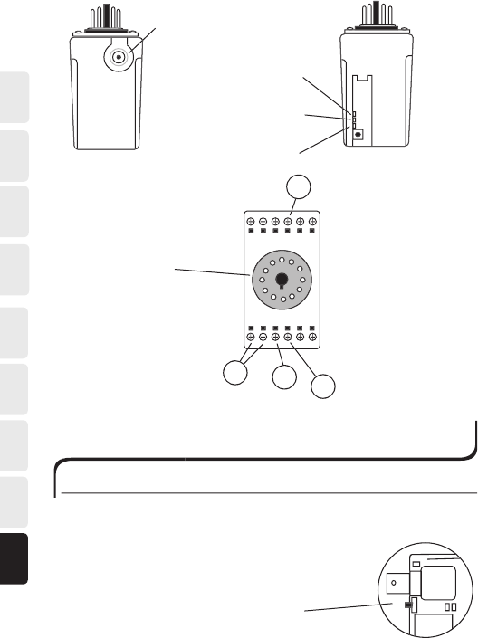
PLUG-IN RECEIVER T60RX-01APL
Frequency: 433.92MHz
Operating voltage: 12-24V AC/DC
Dimensions: 70x58x40mm
Enclosure: IP 23, for internal installation
DK
SE
NL
ES
FRDE
GB
US NO
188
5
6
11
10
Green LED indicates signal
reception.
Button for self-instruction/
erasing.
Red LED indicates
programming status.
Yellow LED indicates supply
voltage.
BNC connector.
Side 1
Side 2
Power connection
11-pin connector
5. 12-24V AC/DC
6. 12-24V AC/DC
10. NO
11. C
PROGRAMMING RECEIVER T60RX-03ADL,
T60RX-01APL, AND T60RX-01ARL
SELF-INSTRUCTION FOR ADJUSTABLE AND FIXED CODES
Register adjustable code:
1. Press the self-instruction button for at least 0.3 seconds, max. 4 seconds.
2. Release the button.
-Programming mode, red LED lights.
3. Press the desired function button.
-Red LED fl ashes rapidly three times.
4. The adjustable code is now stored.
-Red LED fl ashes. Once every other second.
T60TX-15SML AND T60RX-03ADL
SE
NLES
FR
DE
GB
US NO DK
189
SELF-INSTRUCTION FOR ADJUSTABLE AND FIXED CODES
Register adjustable code:
Register fixed individual code:
1. Press the self-instruction button for at least 0.3 seconds, max. 4 seconds.
2. Release the button (less than 1 second).
3. Press the button again (longer than 1 second).
-Private program mode, red LED goes out and lights again.
4. Press the desired function button.
-Red LED fl ashes rapidly three times.
5. The private code is now stored.
-Red LED double-fl ashes every other second.
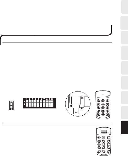
CO-PROGRAMMING THE TRANSMITTER AND
DIN-RECEIVER
T60TX-15SML AND T60RX-03ADL
1. Check that the transmitter’s system switch (A) is in the ON position.
2. Set a unique code on the transmitter’s code switch (B) 1-10.
3.
Press the self-instruction button (C) on the receiver.
-Red LED lights (programming mode 6 seconds).
4. If buttons 1-3 are pressed, the relays in the receiver will function as
buttons 1-3. If buttons 4-6 are pressed, the relays in the receiver will
function as buttons 4-6, and so on.
5. Press the desired function button (1-15) on the transmitter.
-Red LED fl ashes three times.
6. Check that the relay switches when the same function button
is
pressed again.
(A)
(B)
(C)
ON
1
4
123 56789 1
0
+
0
T60TX-15DML AND T60RX-03ADL
1. Check that the transmitter’s system switch (A) is in the ON
position.
2. Set a unique code on the transmitter’s code switch (B) 1-10.
3. Press the self-instruction button (C) on the receiver.
-Red LED lights (programming mode 6 seconds).
DK
SE
NL
ES
FRDE
GB
US NO
190
4. Press the desired port number button (0-999) and an optional function
button (up, stop, down) on the transmitter.
-Red LED fl ashes three times.
5. Check that the relay switches when one of the transmitter buttons is
pressed again.
T60TX-0XSHL/-SOL/-STL AND T60RX-03ADL
1. Check that the transmitter’s system switch (A) is in the ON
position.
2. Set a unique code on the transmitter’s code switch (B) 1-10.
3. Press the self-instruction button (C) on the receiver.
-Red LED lights (programming mode 6 seconds).
4. If buttons 1-3 are pressed, the relays in the receiver will
function as buttons 1-3. If buttons 4-6 are pressed, the
relays in the receiver will function as buttons 4-6, and so on.
5. Press the desired function button (1-6) on the transmitter.
-Red LED fl ashes three times.
6. Check that the relay switches when the same function
button is pressed again.
41 2 3 5 6 7 8 9 1
0
(A)
(B)
ON
1
(C)
4
123
5678
9 1
0
4
123 56789 1 0
+
0
3
456
31 2
1 2
T60TX-15DML*
Type 401RVL9 and 403RVL9 transmitters with knob 1-10:

SE
NLES
FR
DE
GB
US NO DK
191
SUPPLEMENT FOR THE 460 SYSTEM
T60TX-15DML*
Type 401RVL9 and 403RVL9 transmitters with knob 1-10:
1. Check that the transmitter’s system switch (A) is in position 1 (OFF).
2. Check that code switch (B) 9 is in the 0 (zero) position.
3. Set code switch 10 to either the minus or plus position depending on
whether you are using A or B coding on the old transmitter (robust
transmitter).
4. Set a code on the transmitter’s 4 fi rst switches (code switches 1-4)
identical to the receiver’s (code switches 5-8 not used).
5. Check that the relay switches when one of the transmitter buttons is
pressed. The numbers on the transmitter display correspond to the
knob. Press a number followed by the transmit button and verify that
the corresponding relay switches. See code table 1-10, Appendix A.
* Transmitter T60TX-15DML in the T60 system is compatible with
transmitter Type 401RVL9 and 403RVL9 in the 460 system.
(A)
(B)
4
123
56789 1
0
+
0
ON
1
Type 401RVL9 and 403RVL9 with knob 0-15:
1. Check that the transmitter’s system switch (A) is in position 1 (OFF).
2. Check that code switch (B) 9 is in the - (minus) position.
3. Set code switch 10 to either the minus or plus position depending on
whether you are using A or B coding on the old transmitter (robust
transmitter).
4. Set a code on the transmitter’s 4 fi rst switches (code switches 1-4)
identical to the receiver’s (code switches 5-8 not used).
5. Check that the relay switches when one of the transmitter buttons is
pressed.
See code table 0-15, Appendix B.
DK
SE
NL
ES
FRDE
GB
US NO
192
Type 460-93 transmitter:
1. Check that the transmitter’s system switch (A) is in position 1 (OFF).
2. Check that code switch (B) 9 is in the + (plus) position.
3. Set codes on the transmitter’s 3 fi rst switches (code switches 1-3)
identical to the receiver’s codes (code switches 4-8 not used).
4. Check that the relay switches when one of the transmitter buttons is
pressed.
See code table 460-93, Appendix C.
Note:
When you select the port on the T60TX-15DML transmitter, a combina-
tion of the fi rst digit and the last two digits is entered when used together
with a 460-93 transmitter.
Example
: In order to control port A2 in accordance with table A, enter
the combination 102; to control port D3 in accordance with table D, enter
the combination 403; and so on.
T60TX-0XSHL/-SOL/-STL AND T60TX-15SML
Type 401L-406L transmitter:
1. Check that the transmitter’s system switch (A) is in position 1 (OFF).
2. Set codes on the transmitter’s code switches (B) 1-8 identical to the
existing receiver (9-10 not used).
3. Check that the relay switches when the same function button is
pressed again.
(A)
123
456
1 2 3
ON
1
(B)
4
123 56789 1
0
+
0

SE
NLES
FR
DE
GB
US NO DK
193
SERVICING AND MAINTENANCE
SERVICING
If you require servicing or support, or if you need to return an item or
make a complaint, please contact your dealer.
When contacting a dealer regarding a servicing or support matter, please
have the following information to hand: System, model and a description of
the problem.
If you subsequently need to return an item or make a complaint, it would
make matters easier if you could please include information regarding
invoice number and delivery date.
NOTE! The warranty does not apply to faults that have arisen due to modifi cations to
products, incorrect installation or abnormal use.
RECYCLING, SCRAPPING
T60 systems and any accessories and spare parts no longer in use should
be scrapped and recycled according to local environmental regulations.
DK
SE
NL
ES
FRDE
GB
US NO
194
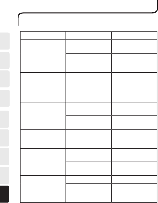
FAULTY FUNCTION
POSSIBLE CAUSES
REMEDY
The receiver does
not work when you
transmit.
The receiver is incor-
rectly connected.
Inspect receiver con-
nections.
Incorrect operat-
ing voltage to the
receiver.
Check the supply
voltage.
The receiver’s green
LED lights when you
transmit, but the re-
lays are not activated.
The codes in the
transmitter and
receiver do not cor-
respond, i.e., they are
not identical.
Check the coding.
The receiver’sgreen
LED does not light
when you transmit.
The battery is dis-
charged.
Replace the battery.
The transmitter is
damaged.
Contact your dealer
.
The receiver’s green
LED lights when you
are not transmitting.
Another unit is trans-
mitting in the vicinity
on a similar frequency.
Contact your dealer
.
The transmitter’s LED
does not light when
you transmit.
The battery is dis-
charged.
Replace or charge the
battery.
The transmitter is
damaged.
Contact Tele Radio’s
support.
The range istoo short.
Bad battery.
Replace the battery.
Aerial cables are dam-
aged or incorrectly
installed.
Check the aerial
connection.
TROUBLE SHOOTING CHART
If the equipment is not working as it should, we would ask you to follow
the steps below.
If you have followed these instructions and still cannot get the radio system to work properly,
please contact your dealer.

SE
NLES
FR
DE
GB
US NO DK
195
TELERADIO COMPANY TERMS AND CONDITIONS OF SALE
1. AGREEMENT: The Purchaser grants to TeleRadio and TeleRadio retains a
security interest in all equipment shipped pursuant to this contract and the
proceeds thereof until the Purchaser shall have made full payment for the
equipment. In the event of a failure to make payment on the date when due
in accordance with the terms designated, the entire balance shall become
due and payable at once. In case of default of payment, TeleRadio shall have
the right to enter the premises of purchaser and take possession of the
equipment immediately, wherever it may be found, and remove it with or
without process of law and may retain all money paid hereunder as liquida-
ted damages and rental for said equipment. While any amounts are payable
to TeleRadio, the Purchaser shall not sell, mortgage, pledge or lease said
TeleRadio equipment without the prior written permission of TeleRadio.
2. WARRANTIES: Subject to the limitations below, TeleRadio warrants all of
its products to be free from material defects in material and workmanship.
However, TeleRadio’s liability under such warranty shall be limited to repair
or replacement of any product which TeleRadio’s inspection shall disclose
to have been defective. This warranty does not apply to any products, which
have been subject to abuse, mishandling, or improper use, and does not
include field labor of any type. TeleRadio’s quotation does not include price
provision for performance bond of indemnity. Therefore, the additional cost
incurred to provide such a bond shall be added to the total amount of this
quote and paid by Purchaser. The warranty period for any equipment ship-
ped hereunder is one (1) year and covers all labor and material manufactu-
red by TeleRadio, provided Purchaser returns them to the factory for repair.
Defective items will be repaired or replaced free of charge at TeleRadio’s
discretion, during the one- (1) year term of this warranty. Freight and/or
postage are not covered by said warranty and will be paid by Purchaser. Any
services rendered in the field will be performed at current rates for time
and travel at the discretion of TeleRadio and will be paid by the Purchaser.
All commercial grade products of TeleRadio carry a warranty period of one
(1) year. Batteries, cases, switches, and such other items subject to normal
wear and deterioration are not included in this warranty.
TeleRadio’s warranty period begins at system receipt after direct shipment
to the Purchaser.

DK
SE
NL
ES
FRDE
GB
US NO
196
-
IN NO EVENT WILL TELERADIO BE LIABLE FOR INDIRECT, SPECIAL,
INCIDENTAL OR CONSEQUENTIAL DAMAGES.EXCEPT AS STATED
ABOVE, TELERADIO MAKES NO REPRESENTATIONS OR WARRANTIES,
EXPRESSED OR IMPLIED, NO OTHER REPRESENTATION OR
WARRANTY IS GIVEN, AND NO AFFIRMATION OF TELERADIO OR
ITS REPRESENTATIVES BY WORD OR ACTION SHALL CONSTITUTE
A WARRANTY. THERE ARE NO WARRANTIES WHICH EXTEND
BEYOND THE ONE (1) YEAR PERIOD DESCRIBED HEREIN. TELERADIO
SPECIFICALLY DISCLAIMS, AND PURCHASER HEREBY WAIVES, ANY
WARRANTIES OF MERCHANTABILITY OR FITNESS FOR PARTICULAR
PURPOSE.
3. PAYMENT: In the event credit is applied for and granted, terms shall be
net thirty (30) days. All equipment will be invoiced at time of shipment. In
the event any payment is not received according to the terms set forth her-
ein, TeleRadio may, at its discretion, assess interest at the rate of 1 and 1/2
percent per month or the maximum rate allowed by law. The Purchaser also
agrees to pay any reasonable and customary legal fees or agency commis-
sions sustained by TeleRadio in pursuit of any payment which is past due.
4. TAXES: The Purchaser agrees to pay any federal excise, state or local
taxes, if any.
5. PRODUCT OR PRICE CHANGE: The contract, product specification, and
statements concerning products and any published prices are subject to
change without prior notification. The only exceptions are special quotations
and purchase orders accepted by TeleRadio.
6. DELIVERY & LIABILITY: TeleRadio shall not be liable for loss or damage
of any kind resulting from carrier delay, or inability to deliver on account
of Acts of God, fire, labor troubles, accidents, acts of civil or military aut-
horities, fuel, labor or material shortages, or other such conditions beyond
TeleRadio’s control. The promised delivery date is the best estimate pos-
sible based on current and anticipated factory load. All shipments are made
F.O.B. factory dock unless otherwise stated. All transportation, when not
F.O.B. factory dock unless otherwise stated. All transportation, when not
specified by Purchaser, will be the least expensive surface transportation.
Costs of packing for domestic shipment are included in the quoted price.
Any special packing may result in additional charges to Purchaser.

SE
NLES
FR
DE
GB
US NO DK
197
FCC STATEMENTS
15.19 - TWO PART WARNING STATEMENT
THIS DEVICE COMPLIES WITH PART 15 OF THE FCC RULES.
OPERATION IS SUBJECT TO THE FOLLOWING TWO CONDITIONS:
(1) THIS DEVICE MAY NOT CAUSE HARMFUL INTERFERENCE, AND
(2) THIS DEVICE MUST ACCEPT ANY INTERFERENCE RECEIVED,
INCLUDING INTERFERENCE THAT MAY CAUSE UNDESIRED OPERA-
TION.
15.21 - MODIFICATION STATEMENT
NOTE: THE MANUFACTURER IS NOT RESPONSIBLE FOR ANY RADIO
OR TV INTERFERENCE CAUSED BY UNAUTHORIZED MODIFICA-
TIONS TO THIS EQUIPMENT. SUCH MODIFICATIONS COULD VOID
THE USER´S AUTHORITY TO OPERATE THE EQUIPMENT.
7. RETURNS & CANCELLATIONS: Orders placed by Purchaser, and ente-
red upon TeleRadio’s books cannot be canceled or changed except with
TeleRadio’s consent and upon terms that will indemnify TeleRadio against all
losses. TeleRadio shall not accept returns without a request and authoriza-
tion issued by it before shipment. All return shipments must be prepaid by
the Purchaser and properly packed. TeleRadio
shall not be responsible for damages incurred during such shipment.
8. GENERAL: All orders are subject to factory acceptance and shall not
be considered a contract unless such order is accepted in writing by an
authorized executive of Teleradio. Teleradio reserves the right to correct any
clerical errors which may occur in quotations. Teleradio shall not be bound
by any statements or promises made by any representative of TeleRadio
which are not stated in and made a part of this contract. This contract is
expressly made subject to the terms and conditions contained herein and
will be interpreted accordingly if a conflict arises with Purchaser or its terms
of purchase. The parties stipulate to the venue and jurisdiction of the courts
located in Allegheny County, Pennsylvania for the resolution of any dispute
that may arise hereunder.
TeleRadio Company, 1006 Corporate Lane, Unit C, Murry Corporate Park,
Export, PA 15632