Tele Radio T60TX-0XSTL T60 MIDI TRANSMITTER User Manual IM T60 001 A5 US FCC OK1 indd
Tele Radio AB T60 MIDI TRANSMITTER IM T60 001 A5 US FCC OK1 indd
UserManual.wiki
>
Tele Radio
>
T60TX 0XSTL User Manual
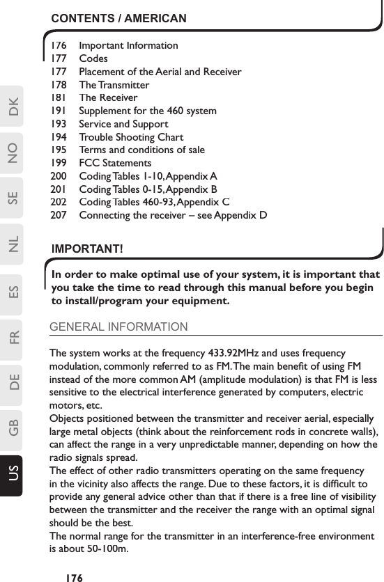
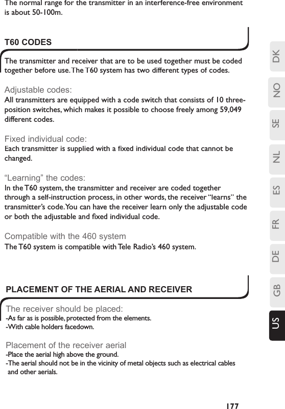
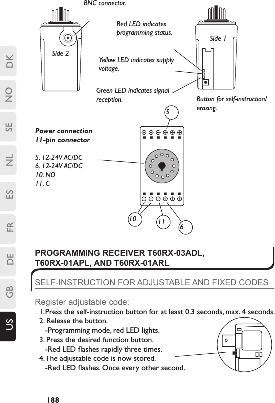
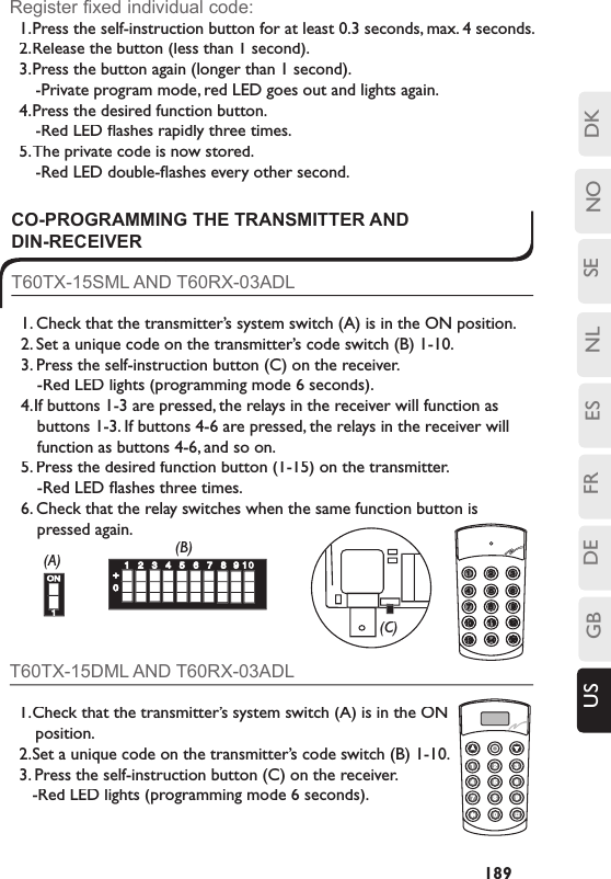
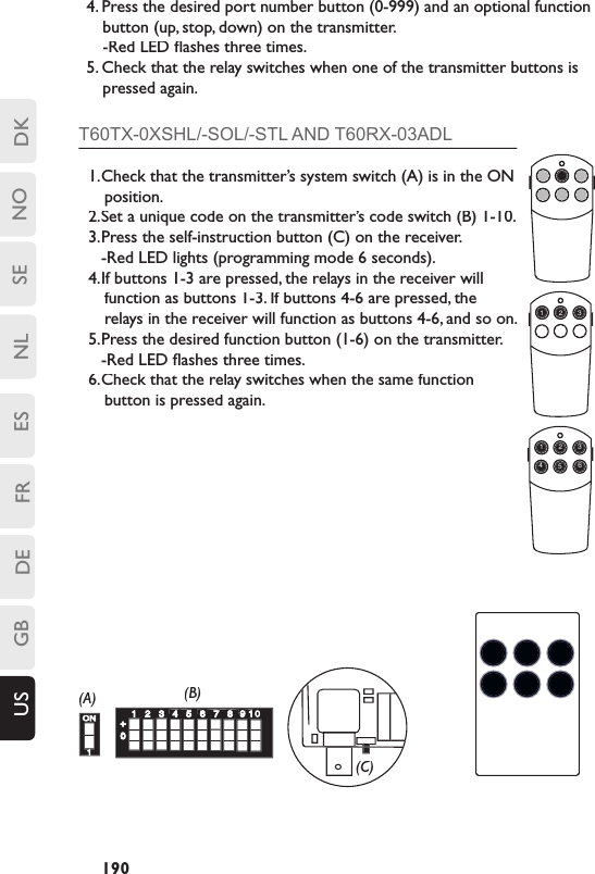
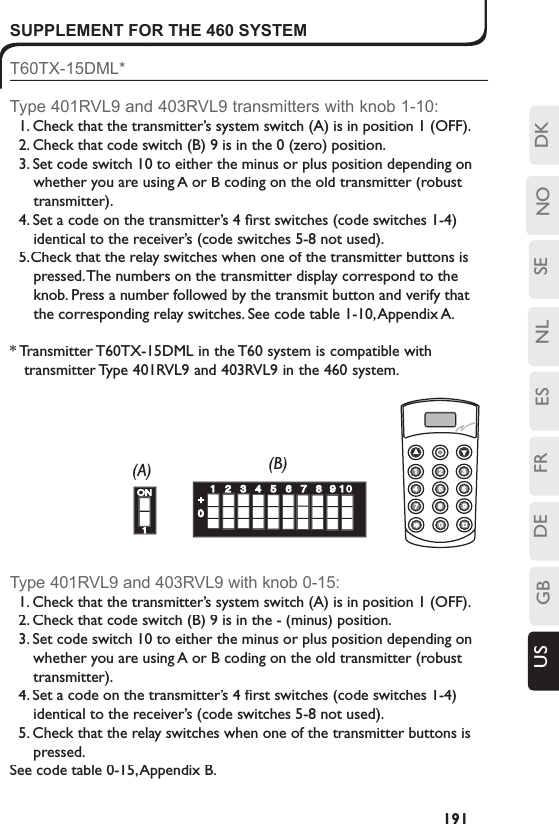
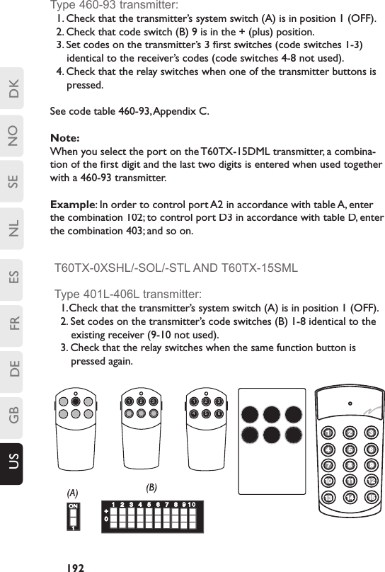
USERS MANUAL
Navigation menu
Upload a User Manual
Namespaces
Wiki Guide
HTML
PDF
Info
Views
User Manual
Discussion / Help
Navigation