Tele Supply AS JTM-30C NDB Transmitter User Manual New strings 15 12 2006
Tele Supply AS NDB Transmitter New strings 15 12 2006
user manual

TELE SUPPLY AS
Rev Date
Rev.
Document ID
June 7th 2016
PN2
5. OPERATOR MANUAL JTM-30
Prepared by
Approved by
Magne Strandengen
Geir Jacobsen
5. JTM-30C NDB Operator User Manual
Copyright 2014 - TELE SUPPLY AS
Page 1(14)
5. OPERATION AND MONITORING OF THE NDB TRANSMITTER TYPE JTM-30C ............ 2
5.1 OPERATION FROM REMOTE CONTROL UNITS TYPE JTM-30R ........................................................... 2
5.1.1 LED indication DC Voltage input to the Transmitter «DC ON». .............................................. 2
5.1.2 LED indication «RF Output» from the Transmitter «CARR» .................................................... 3
5.1.3 LED indication Morse signal «MOD» ....................................................................................... 3
5.1.4 LED indication Alarm «ALARM» .............................................................................................. 3
5.1.5 Switch for switching the Transmitter ON/OFF/Remote Activate/Deactivate/Remote» .............. 3
5.1.6 Switch for switching the local Loudspeaker ON/OFF................................................................ 3
5.2 OPERATION FROM PC ......................................................................................................................... 3
5.2.1 MONITORING ONLY (level 0) .................................................................................................. 4
5.2.2 OPERATOR (Level 1) ............................................................................................................... 4
5.2.3 ADMINISTRATOR (Level 2) ...................................................................................................... 5
5.3 COLOR AND NUMBER INFORMATION ON THE PC ................................................................................ 5
5.3.1 Power (WPEP) ........................................................................................................................... 5
5.3.2 Current /A) ................................................................................................................................. 6
5.3.3 Power Amplifier Temp (C) ......................................................................................................... 6
5.3.4 Antenna VSWR ........................................................................................................................... 6
5.3.5 Ambient Temp (C) ...................................................................................................................... 6
5.4 OPERATION FROM PC LOCALLY OR VIA INTERNET (SINGLE SITE MODE).......................................... 6
5.4.1 RUN ............................................................................................................................................ 8
5.4.2 RUN ............................................................................................................................................ 8
5.4.3 AUTO LEVEL ............................................................................................................................. 9
5.4.4 IDLE ........................................................................................................................................... 9
5.4.5 STOP .......................................................................................................................................... 9
5.4.6 READ .......................................................................................................................................... 9
5.4.7 BLOCK A/B ................................................................................................................................ 9
5.4.8 TRANSMITTER RESET .............................................................................................................. 9
5.5 OPERATION FROM PC LOCALLY OR VIA INTERNET (MULTI SITE MODE)........................................... 9
5.6 FCC STATEMENTS FOR POWER SUPPLY ASSEMBLY HWS300-24 .................................................... 13
5.6.1 Compliance Statement (Part 15.19.) ........................................................................................ 13
5.6.2 Warning (Part 15.21) ............................................................................................................... 13
5.6.3 FCC Interference Statement (Part 15.105 (b)) ......................................................................... 13
5.7 IC STATEMENTS FOR POWER SUPPLY ASSEMBLY HWS300-24 ....................................................... 14
5.7.1 English ...................................................................................................................................... 14
5.7.2 French ...................................................................................................................................... 14
Document ID
Rev.
Rev Date
5. OPERATOR MANUAL JTM-30
PN2
June 7th 2016
5. JTM-30C NDB Operation User Manual
Copyright 2014 - TELE SUPPLY AS
Page 2(14)
5. OPERATION AND MONITORING OF THE NDB TRANSMITTER TYPE JTM-30C
Operation and monitoring of the NDB Transmitter is possible with external mounted Remote Controls and/or
operation for dedicated PC directly connected to the equipment, or from PC via Internet
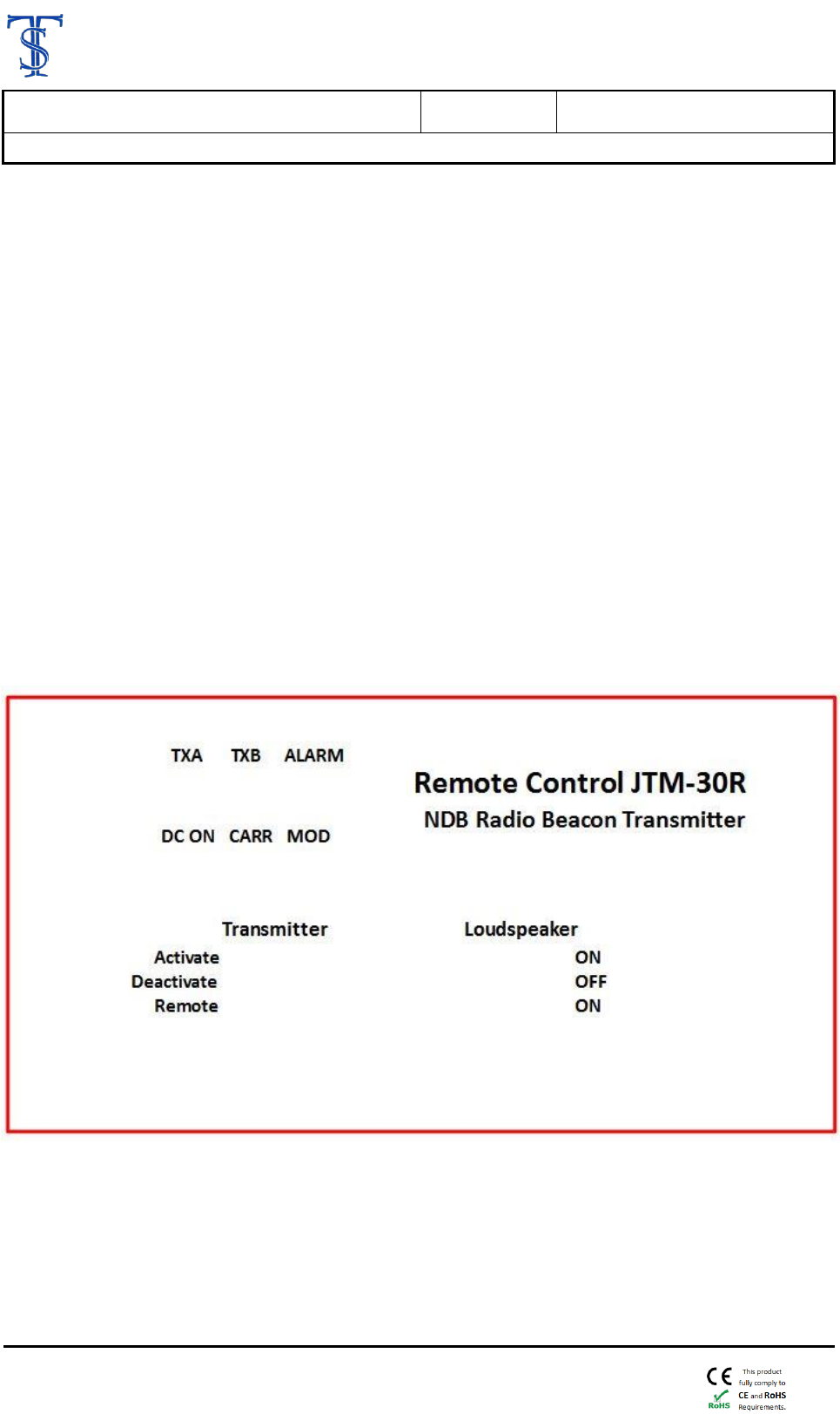
5.1 Operation from Remote Control Units Type JTM-30R
Switching the equipment ON (Activate), OFF (Deactivate) and Remote.
Remote Control Units may be daisy chained.
The Remote Control is provided with following indicators and switches:
• LED indicating DC Voltage input to the Transmitter «DC ON»
• LED indicating which transmitter in operation «TXA» or «TXB»
• LED Indicating sufficient «RF Output» from the Transmitter «CARR»
• LED indicating Morse signal «MOD»
• LED indicating Alarm «ALARM»
• Switch for switching the Transmitter ON/OFF/Remote
«Activate/Deactivate/Remote»
• Switch for switching the local Loud Speaker ON or OFF
Front Panel view
5.1.1 LED indication DC Voltage input to the Transmitter «DC ON».
If this LED is lit it indicates that there is DC supply voltage (nominal 24V DC) into
the NDB Transmitter, and that the Fuse F1 inside the Transmitter cabinet is ON

Rev Date
Rev.
Document ID
May 12th 2016
PN1
5. OPERATOR MANUAL JTM-30
5. JTM-30C NDB Operation User Manual
Copyright 2014 - TELE SUPPLY AS
Page 3(14)
LED indication which transmitter in operation «TXA» or «TXB»
If LED marked «TXA» is lit it indicates that the Main Transmitter is in operation.
As DUAL Transmitter the equipment starts with «TXA» in operation and change-
over to «TXB» if the RF output is to low, or if failure
The change-over will take place approx. after 1 minute, if failure
If LED marked «TXB» is lit it indicates that the Reserve Transmitter is in operation.
As SINGLE Transmitter, only «TXB» is in operation
5.1.2 LED indication «RF Output» from the Transmitter «CARR»
If LED marked «CARR» is lit it indicates that the transmitter in generating sufficient
RF output energy to the Antenna.
If the RF Output, for transmitter in operation, fails the «CARR» LED will be unlit
5.1.3 LED indication Morse signal «MOD»
The LED marked «MOD» will be blinking as the Morse signal progresses
If this LED is not blinking it is an indicting that the Transmitter is not sending any
Morse signal
5.1.4 LED indication Alarm «ALARM»
If both Transmitters («TXA» and «TXB»), for some reason, stops sending Morse
and/or do not generate sufficient RF carrier output the LED marked «ALARM» will
be lit
The equipment will now either switch itself OFF or continue to transmit with low
power depending on the Exciter programming
5.1.5 Switch for switching the Transmitter ON/OFF/Remote
Activate/Deactivate/Remote»
If the Transmitter is in operation and turning this switch from Deactivate to Activate
nothing will happen
If the Transmitter is in operation and turning this switch from Activate to Deactivate
the Transmitter will switch OFF
If the switch is set in position «Remote» the next Remote Control takes over
5.1.6 Switch for switching the local Loudspeaker ON/OFF
The Remote Control has a built-in loudspeaker
If this switch is in position ON you will hear the Morse signal in this internal loud
speaker
It the RF Output is very low (change-over or Alarm situation) you may not hear
Morse signal in this loudspeaker
5.2 Operation from PC
Operation and monitoring of the NDB Transmitter is possible from a dedicated PC directly connected
to the equipment, or from PC via Internet.
As operator you have two alternatives. “Monitoring only” or “Operator”.

Document ID
Rev.
Rev Date
5. OPERATOR MANUAL JTM-30
PN2
June 7th 2016
5. JTM-30C NDB Operation User Manual
Copyright 2014 - TELE SUPPLY AS
Page 4(14)
It is only possible to Monitor or Operate the Transmitter from one (1) PC ONLY.
Once a PC is connected to the Transmitter directly, connected to the Transmitter or via Internet,
no other PC may Monitor or Operate the Transmitter.
From the Remote Control Panels connected to the Transmitter, you may at any time switch OFF
or switch ON the Transmitter irrespective the status of the PC connection.
From PC you may Monitor or Operate a SINGLE Transmitter or any of the other Transmitters
via the MULTI Site selection.
As OPERATOR you only have «Priority 1» access.
5.2.1 MONITORING ONLY (level 0)
This function is meant for monitoring only of one (“Single Site”) or several (“Multi Site”) NDB
Transmitters over Internet from PC.
The equipment may be monitored from an external PC via one pair of wires
+ ground cable connected to a RS-485 /USB Interface box at the PC.
When logged in to the PC as “General user” (level 0) you may only monitor the equipment such as:
Monitoring which Transmitter in operation (Main or Reserve)
Monitoring RF Output power
Monitoring DC input Current to the equipment
Monitoring temperature at the High Power Amplifier (HPA)
Monitoring Tuning Condition (VSWR)
Monitoring ambient temperature (temperature inside transmitter cabinet)
Monitoring if the equipment gives an alarm
Check RF Power Output and other conditions on both Transmitter
Reading event log that records all system events, such as restart, parameter changes and
error events
5.2.2 OPERATOR (Level 1)
The equipment may be fully controlled and monitored from an external PC via one pair of wires
+ ground cable connected to a RS-485 /USB Interface box at the PC.
Distance between Transmitter and PC may be as long as required (up to 500m).
When logged in to the PC as “General user” (level 1) you only may perform normal Operation and
monitoring of the equipment such as :
Switching the equipment ON or OFF
Monitoring which Transmitter in operation (Main or Reserve)
Monitoring RF Output power
Monitoring DC input Current to the equipment
Monitoring temperature at the High Power Amplifier (HPA)
Monitoring Tuning Condition (VSWR)
Monitoring ambient temperature (temperature inside transmitter cabinet)
Monitoring if the equipment gives an alarm
Check RF Power Output and other conditions on both Transmitter
Reading event log that records all system events, such as restart, parameter changes and error events
Rev Date
Rev.
Document ID
May 12th 2016
PN1
5. OPERATOR MANUAL JTM-30
5. JTM-30C NDB Operation User Manual
Copyright 2014 - TELE SUPPLY AS
Page 5(14)
5.2.3 ADMINISTRATOR (Level 2)
NOTE ! This is for information ONLY.
Level 2 access shall only be available for administrator in connection with
configuration of the Transmitter during Commissioning
When logged in to the PC as “Administrator” you may, in addition to “General user” as
specified above, have full access and ability to configure and make adjustment and
monitoring of the Transmitter such as :
Setting Carrier frequency
Setting RF power output
Setting Modulation type - Morse, Audio or MSK (option)
Setting Modulation depth
Setting Morse tone frequency and Morse sequence (ID)
Setting Keying rate
Setting of four (4) different Morse messages
Selection of type of timer and setting of time
RESET of Main or Reserve Transmitter, if failed (Alarm)
Setting User name and Pass words and selection of mode for Reserve Transmitter
Reading event log that records all system events, such as restart, parameter changes and
error events.
(The JTM-30C has a built-in non-volatile memory sufficient for storage of the entire transmitter
configuration, and enabling stand-alone un-attended operation. Saving the configuration in
solid-state memory is controlled via the PC interface).
5.3 Color and number information on the PC
Readings in the PC windows.
The numbers in the windows are not absolute values, but approx. information only for
quick status overview.
5.3.1 Power (WPEP)
The “Power (WPEP)” window is an indication to check that the Transmitter is
generating RF output to the Antenna. When the Transmitter is switched ON and under
normal condition the background of the window is GREEN, and will be GREEN as log
at the RF Power output is 70% or higher than programmed “RF pow. (%)”.
E.g. if “RF pow. (%)” is configured to 50% and the number in the “Power (WPEP)”
window is above approx. 35 the background is GREEN, but the background will turn to
YELLOW if the number in this window is below approx. 35.
The equipment is still operational if the background is YELLOW, but RF output is
reduced due to poor Antenna tuning and/or due to poor cleaning of the Antenna
Insulators.

Document ID
Rev.
Rev Date
5. OPERATOR MANUAL JTM-30
PN2
June 7th 2016
5. JTM-30C NDB Operation User Manual
Copyright 2014 - TELE SUPPLY AS
Page 6(14)
5.3.2 Current /A)
This window shoes the DC current supplied to the Transmitter.
Under normal condition the window is white, and will be white as log at the DC current
is less than 15 Amp. If the DC current is higher than 15 Amps the background turns
RED indicating excessed DC current indicating that the DC drain current to the
Transmitter is too high.
5.3.3 Power Amplifier Temp (C)
This window shoes the temperature (Co) at the Output RF Transistors
When transmitter is switched ON the background of the window is white and will
indicate the temperature on the Output Transistors. During operation the temperature
will increase, but normally not exceed 65 Co.
If the temperature for some reason should increase above 80 Co the background
becomes RED.
The RF Output Amplifier will operate normally up to 90 Co. If exceeding 90 Co the RF
Amplifier will shut-down. When after the RF Amplifier has cooled down to temperature
below70 Co the RF Amplifier will operate normally again.
5.3.4 Antenna VSWR
This window is inserted to have control over the impedance matching and Antenna
Tuning. During ideal conditions the VSWR should show less than 1,5.
The Transmitter is considered operating correctly as long as the VSWR shows below 2,5.
After finishing fine tuning of the Antenna Tuning Coil adjust the Impedance matching
to minimum VSWR.
If the VSWR figures exceed approx. 3,5 the background first turns YELLOW, which is
an indication the Antenna Tuning and/or Impedance matching is not optimal.
The equipment is still operational if the background is YELLOW, but RF output may be
reduced due to poor Antenna tuning and/or due to poor cleaning of the Antenna
Insulators.
If the figure exceeds approx. 5,0 it is an indication the equipment then the
Antenna Tuning is not correct and/or problem with the Antenna or Antenna
Insulators.
5.3.5 Ambient Temp (C)
This window shows the temperature (Co) at the Exciter (temperature inside Transmitter
cabinet).
5.4 Operation from PC locally or via Internet (Single Site Mode)
When starting the PC program
This in order to avoid possible unwanted change of configuration, which was set
during commissioning of the equipment, it is of importance to dedicate a separate
User Name for the OPERATOR.

Rev Date
Rev.
Document ID
May 12th 2016
PN1
5. OPERATOR MANUAL JTM-30
5. JTM-30C NDB Operation User Manual
Copyright 2014 - TELE SUPPLY AS
Page 7(14)
As OPERATOR you are allowed to switch the equipment ON and OFF and to
monitor all transmitter settings.
The PC program is in SINGLE Site mod when the upper right button indicate “Multi
Site”.
Select which Transmitter (Transmitter A or Transmitter) to be controlled or monitored.
When PC is connected to the Transmitter for supervision and control you may use
this PC to switch the Transmitter ON or OFF.
As OPERATOR you will only have access to switch the Transmitter ON or OFF
This shall be the case also if acting as OPERATOR via Internet
As OPERATOR you will, however, see all configuration of the equipment on the
PC
Document ID
Rev.
Rev Date
5. OPERATOR MANUAL JTM-30
PN2
June 7th 2016
5. JTM-30C NDB Operation User Manual
Copyright 2014 - TELE SUPPLY AS
Page 8(14)
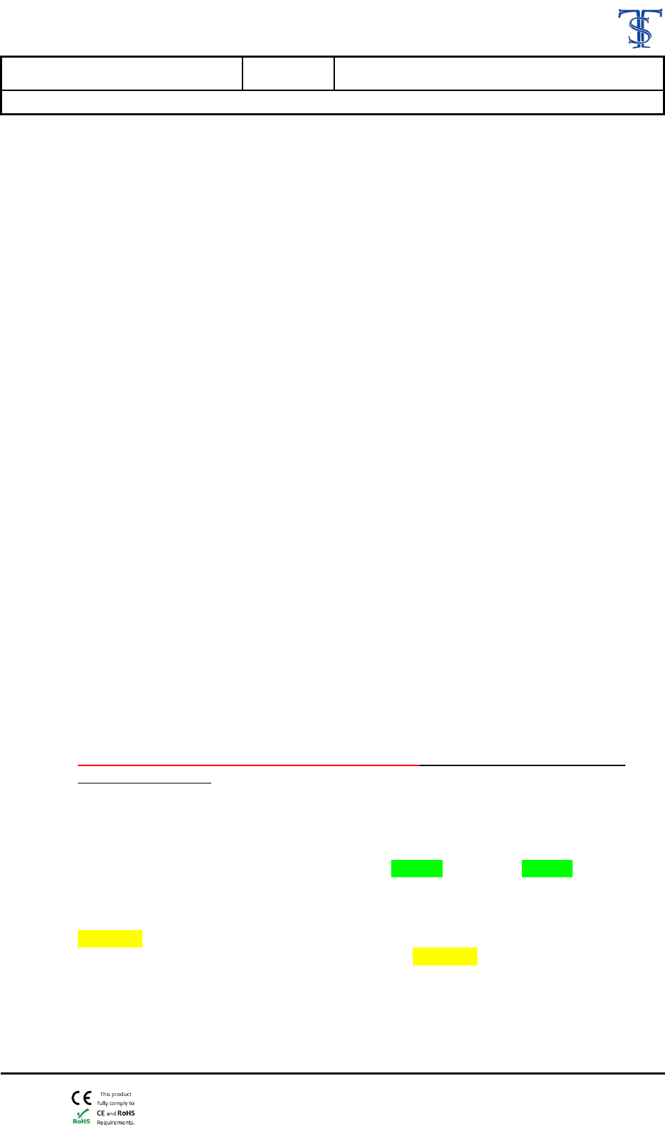
As OPERATOR you only have access to these Control buttons
5.4.1 RUN
When activating “RUN” you switch ON the Transmitter for normal operation.
Carrier ON and sending Morse signals. All monitoring circuits are activated.
5.4.2 RUN
When activating “MAN TUNE” you switch on the Transmitter with the Carrier ON only.

Rev Date
Rev.
Document ID
May 12th 2016
PN1
5. OPERATOR MANUAL JTM-30
5. JTM-30C NDB Operation User Manual
Copyright 2014 - TELE SUPPLY AS
Page 9(14)
5.4.3 AUTO LEVEL
When activating “AUTO LEVEL” you switch ON the Transmitter and start an internal test
and adjustment. When activating you will see that the window “Pwr correction” first turns
YELLOW and becomes GRAY after finishing adjustment of the RF Power Output.
This is an operation which only may be needed when changing the frequency considerably
and/or if replacing the RF Amplifier. Typical value in the “Pwr correction” window is 35
to 40. With RF Amplifier Type JTM-30HPA or JTM-30HPA2 this function is not needed.
5.4.4 IDLE
When activating “IDLE” you switch ON the Transmitter, but without generating RF
input/output from the RF Amplifier. This knob is only to check that the Idle current setting
of the RF Power Output Transistors.
Typical reading in the “Current (A)” window is approx. 0,6 to 0.9.
5.4.5 STOP
When activating “STOP” you switch OFF the Transmitter.
5.4.6 READ
When activating “READ” you ask the Exciter to send updated information on configured
information to the PC.
5.4.7 BLOCK A/B
When activating “BLOCK A/B” you stop the operation on Transmitter in operation.
E.g. if Transmitter “A” is in operation and initiation “BLOCK A” you force the transmitter
to switch over to Transmitter “B”.
5.4.8 TRANSMITTER RESET
If the Transmitter in operation (A or B) stops operation and switches over the upper window
of “TRANSMITTER STATUS” turns RED and indicates Alarm.
If you want to reset the Transmitter, or Alarm status, activate “TRANSMITTER RESET”
and the Transmitter will be reset back to normal operation again.
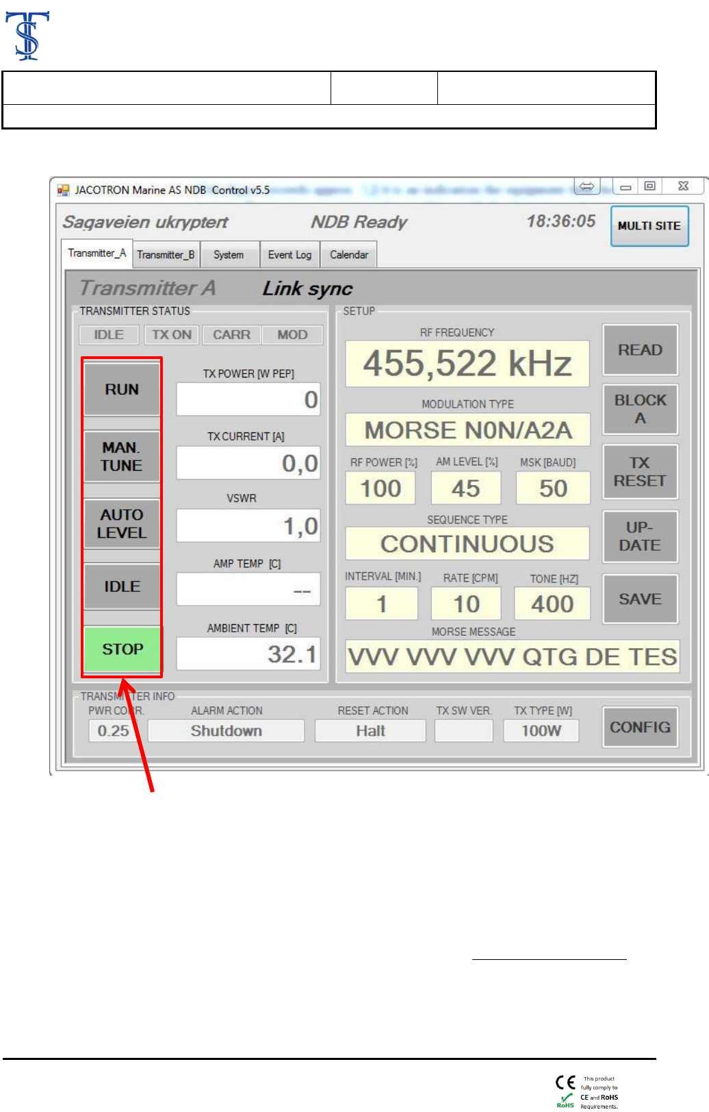
5.5 Operation from PC locally or via Internet (Multi Site Mode)
For “Multi Site Mode” operation activate “Multi Site” block located on upper right PC window
and you will see ”Main Window” to the left and “Multi Site Window” to the right.
Document ID
Rev.
Rev Date
5. OPERATOR MANUAL JTM-30
PN2
June 7th 2016
5. JTM-30C NDB Operation User Manual
Copyright 2014 - TELE SUPPLY AS
Page 10(14)
The new “Multi Site” window enabling monitoring of up to 90 remote located JTM NDB
Transmitters over Internet.
Prior to start monitoring of these NDB Transmitters each one of them needs to be configured.
When all Remote located JTM NDB Transmitters, you want to monitor, has been configured the
name of the station will be displayed and you can start to monitor these stations by activating block
“RUN TEST”.
The scanner program starts to scan one station at the time in series and the status result for each station
(NDB Transmitters) will be displayed.
The program will scan each individual NDB stations one after the other.
Result of this test will be indicated as “CONTROL” “ TESTING”, “ABSENT”, “GOOD”, or
“FAILURE”.
“CONTROL” indicates which NDB Station shown in the Main Window.
“ TESTING” indicates which NDB Transmitter which is under testing at the moment.
“ABSENT”, indicates no data (Internet) connection with this NDB Transmitter
“GOOD”, indicates that the test result with this station is positive. It indicate that the NDB
Transmitter operate as instructed.
“FAILURE” indicates that the result from the test with this station indicate that either Transmitter
“A” or “B” display ALALM.
Main Window Multi Site Window
Rev Date
Rev.
Document ID
May 12th 2016
PN1
5. OPERATOR MANUAL JTM-30
5. JTM-30C NDB Operation User Manual
Copyright 2014 - TELE SUPPLY AS
Page 11(14)
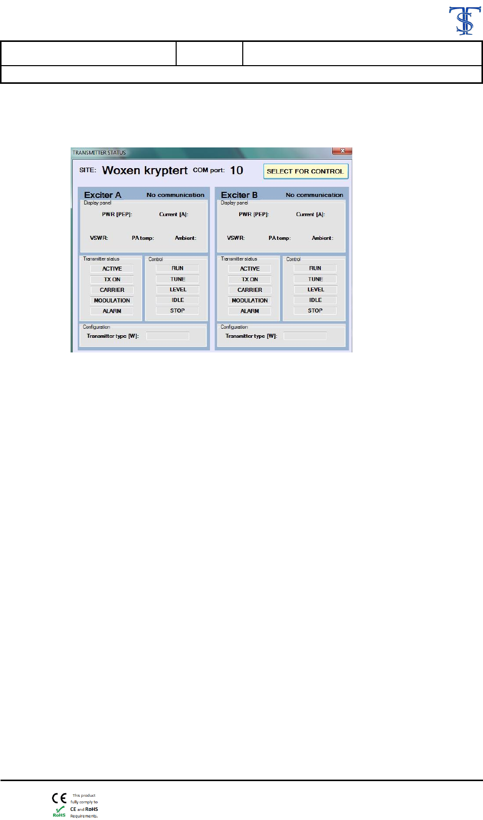
If you want to check more parameter in details of this new station, or start to take control or monitor
selected station under Multi Site window, select the station and a window pops up. See below.
Document ID
Rev.
Rev Date
5. OPERATOR MANUAL JTM-30
PN2
June 7th 2016
5. JTM-30C NDB Operation User Manual
Copyright 2014 - TELE SUPPLY AS
Page 12(14)
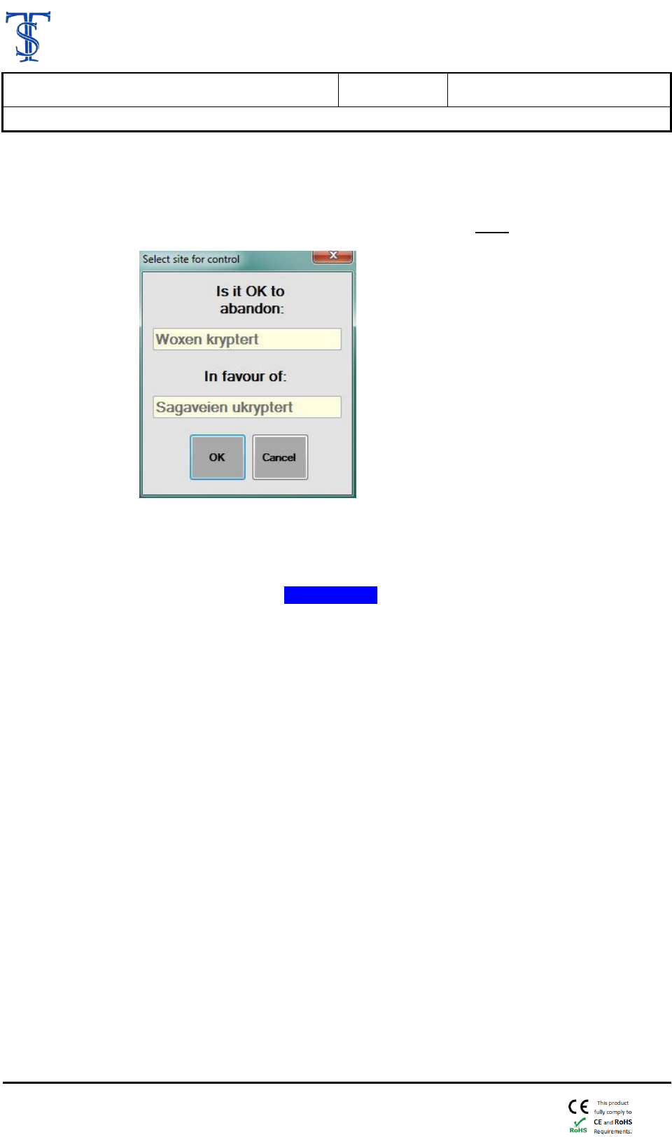
Activate “SELECT FOR CONTROL” and a new Pop-up window.
NOTE! This pop-up window will only be displayed if Multi site TEST is NOT running
You will be asked if is OK to abandon station now under control/monitoring in the main window in favor of
the new selected station in Multi site window.
If activating “OK” the program will from now on use the new selected this station to be displayed in the
Main window and this station will be marked “CONTROL”” in the Multi site window.

Rev Date
Rev.
Document ID
May 12th 2016
PN1
5. OPERATOR MANUAL JTM-30
5. JTM-30C NDB Operation User Manual
Copyright 2014 - TELE SUPPLY AS
Page 13(14)
5.6 FCC Statements for Power Supply assembly HWS300-24
5.6.1 Compliance Statement (Part 15.19.)
This device complies with Part 15 of the FCC Rules. Operation is subject to the following two
conditions:
1. This device may not cause harmful interference, and
2. This device must accept any interference received, including interference that may cause
undesired operation.
The Power Supply Assembly Conducted & Radiated EMI complies to :
EN55011 / EN55022, FCC VCCI Class B
5.6.2 Warning (Part 15.21)
Changes or modifications not expressly approved by the party responsible for compliance could
void the user’s authority to operate the equipment.
5.6.3 FCC Interference Statement (Part 15.105 (b))
This equipment has been tested and found to comply with the limits for a Class B digital device,
pursuant to Part 15 of the FCC Rules. These limits are designed to provide reasonable
protection against harmful interference in a residential installation. This equipment generates,
uses and can radiate radio frequency energy and, if not installed and used in accordance with the
instructions, may cause harmful interference to radio communications. However, there is no
guarantee that interference will not occur in a particular installation.
If this equipment does cause harmful interference to radio or television reception, which can be
determined by turning the equipment off and on, the user is encouraged to try to correct the
interference by one or more of the following measures:
Reorient or relocate the receiving antenna.
Increase the separation between the equipment and receiver.
Connect the equipment into an outlet on a circuit different
from that to which the receiver is connected.
Consult the dealer or an experienced radio/TV technician for help.

Document ID
Rev.
Rev Date
5. OPERATOR MANUAL JTM-30
PN2
June 7th 2016
5. JTM-30C NDB Operation User Manual
Copyright 2014 - TELE SUPPLY AS
Page 14(14)
5.7 IC Statements for Power Supply assembly HWS300-24
5.7.1 English
This device complies with Industry Canada’s Licence-Exempt RSSs. Operation is subject to
the following two conditions:
1) this device may not cause interference, and
2) this device must accept any interference, including interference that may cause
undesired operation of the device.
CAN ICES-3 (B) / NMB-3 (B)
5.7.2 French
Le présent appareil est conforme aux CNR d’Industrie Canada applicables aux appareils radio
exempts de licence. L’exploitation est autorisée aux deux conditions suivantes :
1) l’appareil ne doit pas produire de brouillage;
2) l’appareil doit accepter tout brouillage radioélectrique subi, même si le brouillage est
susceptible d’en compromettre le fonctionnement.
CAN ICES-3 (B) / NMB-3 (B)