TeleEpoch PACE4 PACE4 User Manual
TeleEpoch Limited PACE4
User manual

1
InstructionsforSiteInstallationand
Commissioning
Overview
1. Briefing/TeamedTraining/TechnicalAssistance:TechnicianswhohavenotinstalledPACE+PACECloud
willbebriefedonoperationandinstallation,eitherinperson,viaWebinarortele‐training.Trainingwill
includeinstructionsoninstallation,documentation,closeout,andcontactingtechnicalsupport.
2. AboutInstallingthePACE4Suite:ThePACE4moduleinstallswithinthelowvoltagecontrollines,and
usingadaptivesoftware,periodicallysimulatesathermostat‐satisfiedsignaltocompressor/fanandburner
elementswhilemaintainingtheOEMsequenceofoperationandblower/fanoperationforcooling,toimprove
heattransferduringeithercoolingorheating.Equipmentruntimeisreducedwhilecoolingandheatingis
continued,andaswithanautomobile’sengine,thePACE4module’s“hypermiling”softwareenforces
maximum‐cycleandanti‐shortcyclinglimits.Refertothehelpsectionintheon‐screenmenuformoredetails.
3. PACE4CloudConnectivity:Inadditiontostandaloneofflineoperation,thePACE4modulecanconnect
tothePACE4CloudusingeitherWiFiorCellular(4GLTE)communication.Asingle‐purposecellularorWiFi
antenna,oraCellular+WiFicomboantennawillbeprovidedwhencommunicationisopted‐inbythe
customer.
Cellular:Inthisconfiguration,thePACE4moduleusestheintegratedcellularradioforcommunication,
withouttheneedforanadditionaldevice.
WiFi:Inthisconfiguration,allPACE4modulesatasiteconnectviaWiFi,toacentralWiFitointernet
gateway,whichinturnconnectstoPACE4Cloud.
FeaturesaddedwithPACE4Cloudconnectivityincludetheabilityto:
ParticipateinAutomatedDemandResponseprograms
BypassandprogramPACE4modulesremotely
Remotemonitoringof:
o Thermostatsignals
o PACE4state
o Supply,returnandothertemperaturesdependentonthermistorsinstalled
2
o Energyconsumptionandsavings
(Theconnectionmethodmustbeconfiguredusingtheon‐screenoptionsonthedevice.Refertothe
document“ProjectSpecificGuidelines”todeterminemeansofcommunication)
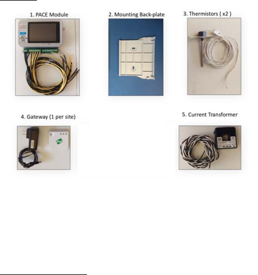
4. Components:ThefollowingcomponentsareincludedintypicalPACE4installations.Theirpurposeand
otherdetailsshallbecoveredduringtraining.
SummaryofSteps
1. InitialHVACData/HVACSurvey:Agoaloftheprojectistocomplete,foreachsite,a100%HVACsite
surveyprovidingthemanufacturer,modelnumber,equipmentconditionnotes,andretrofitsinstalled.AWeb
linkutilitytoassistinthissurveywillbeprovidedtoyou.TheWeblinkistoasitewithpull‐downmenusto
allowanyonewithanInternet‐connectedmobiledevice(phone,tablet,laptop)toentersiteHVACdataand
conditionnotes,anduploadittoadatabaseforthecustomertoreview.ThelinkbelowistotheWeblink:
2.
uni
t
PA
C
bac
3.
du
w
h
24
4.
air
co
m
H
V
Mounti
t
,usingthe
C
E4modul
e
kplate.
PACE4
ringthetr
a
h
ilewiringt
Vsourceis
Installi
n
temperat
u
m
municati
o
V
ACcabinet
ngthehar
d
provided
b
e
intothet
o
NodeInst
a
a
iningtod
e
hePACE44
notavaila
b
n
gOtherC
o
u
resensor
s
o
n,anant
e
(SeeFigur
e
d
ware:Th
e
b
ackplate.
o
plipoft
h
a
llation:A
s
e
terminea
totheHV
A
b
le,thepro
v
o
mponents
s
,acurren
e
nnamust
e
2.).Step‐
b
e
PACE4m
o
Screwthe
h
ebackpla
t
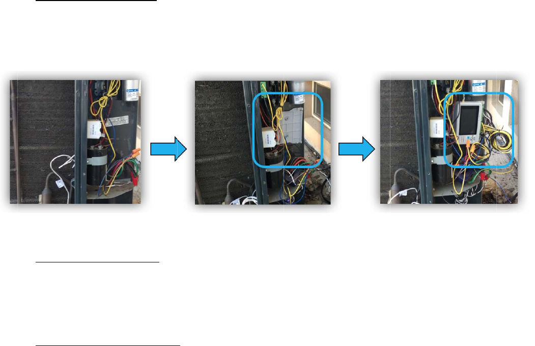
Figure1.
s
sessthe
H
suitableIn
t
A
Ccontrols.
v
idedpow
e
:TypicalP
A
ttransfor
m
beattache
d
b
y‐stepinst
r
o
dulecan
b
back‐plate
t
e,andsna
Mount
i
H
VACunit
s
t
erception
Useanon‐
e
radapter
m
A
CE4install
a
m
er&at
h
d
totheP
A
r
uctionsin
t
b
emounte
d
atanappr
o
pthebott
o
i
ngthePA
C
s
chematics
pointfort
h
board24V
m
aybeuse
d
a
tionsrequ
h
ermalswi
t
A
CE4mod
u
t
hesection
d
insideth
e
o
priatespo
o
mintoth
e
C
E44
andcontr
o
h
ePACE4
N
AC/DCso
u
d
instead.
iretheins
t
t
ch(referr
e
u
le,andm
o
belowpro
v
e
controlc
a
tinsideth
e
e
2clipsat
o
lsandins
N
ode.Refe
r
u
rcetopo
w
t
allationof
e
dtoase
x
o
untedon
v
idedetail
e
a
binetoft
h
e
cabinet.
S
thebotto
m
tructions
p
r
totermin
a
w
erthePAC
E
supplyan
d
x
tendsens
theoutsid
e
e
dinstructi
o
3
h
eHVAC
S
lidethe
m
ofthe
p
rovided
a
llabels
E
44.Ifa
d
return
or).For
e
ofthe
o
ns.
5.
O
n
en
t
be
h
6.
us
e
fo
r
7.
inv
e
att
bas
e
PACE4
n
cepowere
t
eringthe
H
h
avior.
SiteAc
c
e
onlythe
c
r
projectsit
e
Hardw
a
e
ntorydoc
u
echgroup
@
e
duponcu
LTE
A
Port
Configurat
i
d‐up,confi
H
VACunitt
y
c
ess/SiteCl
c
ontactinf
o
e
closeout,
a
reInvento
u
mentation
@
PACE4con
t
rrentwork
A
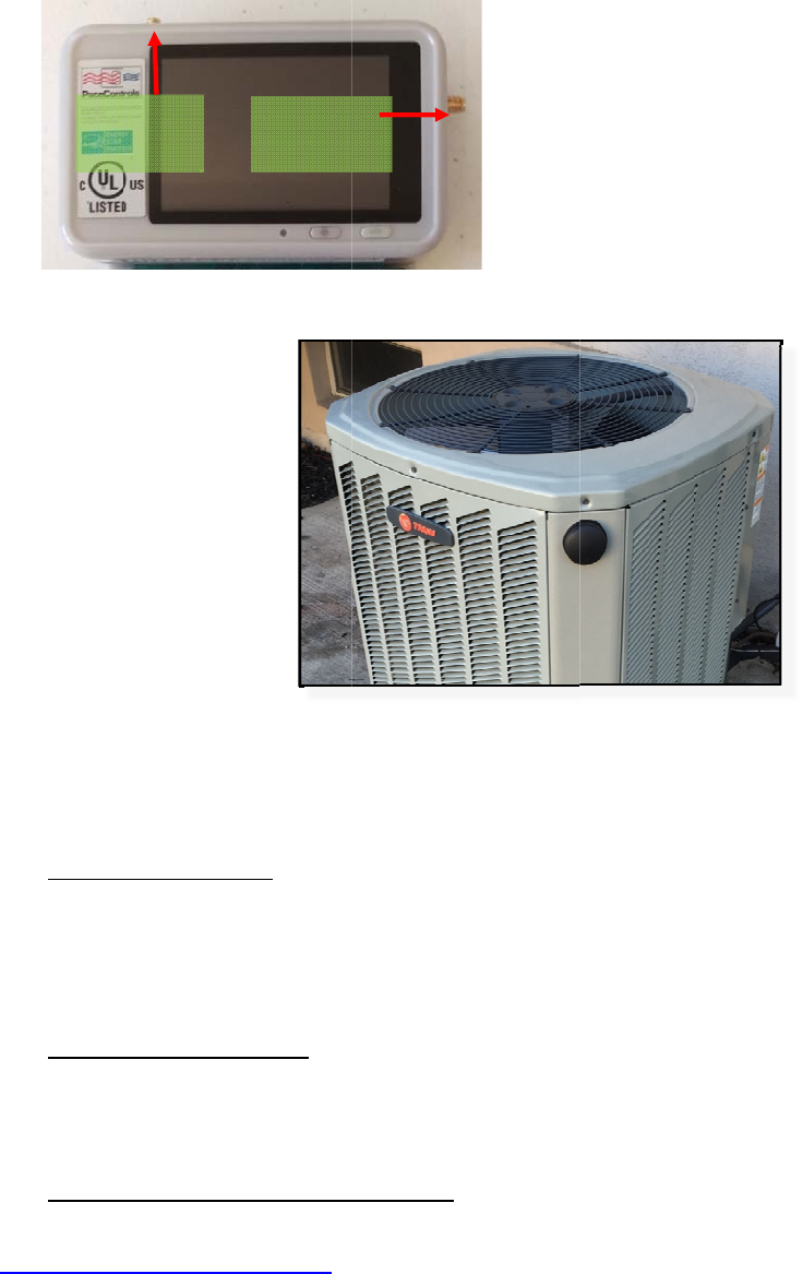
ntenna
Figur
e
i
on:PACE4
m
guretheP
A
y
pe,locati
o
oseout:Pl
e
o
rmationp
r
withsigna
t
ry/Invento
r
provided.
t
rols.comt
o
plans.
WIFIAntenn
Port
e
2.
An
m
odulesa
r
A
CE4node
o
nserviced,
e
asefollo
w
r
ovided.Foll
t
uresobtai
n
r
yControl
:
Attheen
d
o
reportre
m
a
n
tennamou
r
eequippe
d
usingthe
nameplat
e
w
procedure
owinstruc
t
n
edperdir
e
Installing
d
ofeachp
r
m
aininginv
e
ntedonan
d
withan
L
on‐screen
i
e
data,and
o
soutlined
b
t
ionsonth
e
e
ctionofth
e
technician
s
r
ojectday,
t
e
ntoryand
HVACunit
L
CDtouchs
i
nstruction
s
o
therpara
m
b
yclientpr
e
HVACsur
e
clientpro
j
s
shouldre
f
t
echnicians
makereq
u
creentoa
l
s
.Configur
a
m
eterstot
w
ojectstaff
f
veywebli
n
j
ectstaffo
r
f
ertopac
k
shoulde‐
m
u
estsfora
d
l
lowconfig
a
tionsteps
w
eaktheal
g
f
orsiteacc
e
n
korasde
s
r
PACE4Co
n
k
inglistsa
n
m
ailPACE4
C
d
ditionalin
v
4
uration.
include
g
orithm
e
ss,and
s
ignated
n
trols.
n
dother
C
ontrols
v
entory,
5
FCC Statement
§ 15.19 Labeling requirements.
This device complies with part 15 of the FCC Rules. Operation is subject to the following two conditions: (1)
This device may not cause harmful interference, and (2) this device must accept any interference received,
including interference that may cause undesired operation.
§ 15.21 Information to user.
Any Changes or modifications not expressly approved by the party responsible for compliance could void the
user's authority to operate the equipment.
§ 15.105 Information to the user.
Note: This equipment has been tested and found to comply with the limits for a Class B digital device, pursuant
to part 15 of the FCC Rules. These limits are designed to provide reasonable protection against harmful
interference in a residential installation. This equipment generates uses and can radiate radio frequency energy
and, if not installed and used in accordance with the instructions, may cause harmful interference to radio
communications. However, there is no guarantee that interference will not occur in a particular installation. If
this equipment does cause harmful interference to radio or television reception, which can be determined by
turning the equipment off and on, the user is encouraged to try to correct the interference by one or more of the
following measures:
-Reorient or relocate the receiving antenna.
-Increase the separation between the equipment and receiver.
-Connect the equipment into an outlet on a circuit different from that to which the receiver is connected.
-Consult the dealer or an experienced radio/TV technician for help.
This equipment complies with FCC radiation exposure limits set forth for an
uncontrolled environment. This equipment should be installed and operated withminimum distance 20cm
between the radiator & your body.