Teledyne Controls a business unit of Teledyne Technologies WQAR-364-4R Wireless Groundlink(R) Quick Access Recorder User Manual WGL Comm Operations Guide
Teledyne Controls, a business unit of Teledyne Technologies Wireless Groundlink(R) Quick Access Recorder WGL Comm Operations Guide
user guide
501 Continental Blvd. UG2243800-300
El Segundo, CA 90245 USA Sep 16, 2013-Revised Nov 12, 2013
WQAR
WIRELESS GROUNDLINK® - QUICK ACCESS RECORDER
PART NUMBER
2243800-360 2243800-362 2243800-364
USER'S GUIDE

P a g e | i
Use and disclosure shall be in accordance with the proprietary legend and DCS located on page i.
UG2243800-300 Sep 16, 2013
Revised Nov 12, 2013
PROPRIETARY STATEMENT: This is confidential and proprietary information
of Teledyne Controls and may not be used or disclosed by the recipient
without the prior written consent of Teledyne Controls and then only in
accordance with specific written instructions of Teledyne Controls. By
receipt hereof, in addition to any obligation the recipient has under any
confidentiality agreement with Teledyne Controls, neither recipient nor its
agents, representatives or employees will copy, reproduce or distribute this
information, in whole or in part, at any time, without the prior written
consent of Teledyne Controls and that it will keep confidential all information
contained herein.
DESTINATION CONTROL STATEMENT (DCS):
These commodities, technologies, and/or software are exported from the
United States in accordance with the US Export Administration Regulations.
Diversion contrary to U.S. law is prohibited. U.S. prohibits disposition of
these commodities to any end operator for any end use related to the
design, development, production, stockpiling or use of chemical, biological or
nuclear weapons, or missiles, without the prior approval of the U.S.
Government.
© Copyright 2012 by Teledyne Controls All rights reserved. Printed in the U.S.A.
No part of this document may be transmitted, reproduced, or copied in any form
or by any means without the prior written consent of Teledyne Controls Inc. Due
to Teledyne Controls commitment to constantly improve the quality and
performance of our products, information contained in this document is subject
to change without notice.
Teledyne Controls
501 Continental Boulevard.
El Segundo, CA 90245

P a g e | ii
Use and disclosure shall be in accordance with the proprietary legend and DCS located on page i.
UG2243800-300 Sep 16, 2013
Revised Nov 12, 2013
US Federal Communication Commission (FCC) and
Industry Canada (IC) User Notifications.
Interference (FCC part 15.19 / IC RSS-GEN ch. 7.1.3)
This device complies with FCC part 15 and Industry Canada license-exempt RSS
standards. Operation is subject to the following two conditions:
1. this device may not cause interference, and
2. this device must accept any interference, including
interference that may cause undesired operation of the
device.
Le présent appareil est conforme aux CNR d'Industrie Canada applicables aux
appareils radio exempts de licence. L'exploitation est autorisée aux deux
conditions suivantes :
1. l'appareil ne doit pas produire de brouillage, et
2. l'utilisateur de l'appareil doit accepter tout brouillage
radioélectrique subi, même si le brouillage est susceptible
d'en compromettre le fonctionnement.
Modifications
Changes or modifications made to this equipment not expressly approved by
the manufacturer Teledyne Controls may void the FCC and IC authorization to
operate this equipment.
RF Exposure
Radio Frequency (RF) radiation exposure Information:
This equipment complies with FCC and IC radiation exposure limits set forth for
an uncontrolled environment. This equipment should be installed and operated
with a minimum distance of 20 cm between its RF radiating structures and human

P a g e | iii
Use and disclosure shall be in accordance with the proprietary legend and DCS located on page i.
UG2243800-300 Sep 16, 2013
Revised Nov 12, 2013
bodies. Co-location of this transmitter (simultaneous transmission) with other
transmitters shall be subject to maximum exposure re-evaluation.

P a g e | iv
Use and disclosure shall be in accordance with the proprietary legend and DCS located on page i.
UG2243800-300 Sep 16, 2013
Revised Nov 12, 2013
Contents
Table of Figures ................................................................................ v
Definitions ....................................................................................... vi
Section 1 – General ........................................................................... 5
Introduction .......................................................................................... 5
Scope of this document ......................................................................... 6
WQAR Operation Overview ................................................................... 6
Aircraft Signaling ...................................................................................................7
ACMS Reporting ....................................................................................................7
RF Interlocks ..........................................................................................................8
Mobile Networks ...................................................................................................8
Download on Demand (DOD) ................................................................................8
Run Control .........................................................................................................11
Section 2 – System Overview ......................................................... 120
Boot up and Pre-Flight Operations ...................................................... 120
In-Flight Operations ........................................................................... 120
Post Flight Operations ........................................................................ 120
Upgrading and Configuring Your WQAR .............................................. 131
Section 3 – WQAR Operations ....................................................... 153
Front Panel ........................................................................................ 153
Front Panel Display ............................................................................ 153
FAIL Indicator ..................................................................................... 186

P a g e | v
Use and disclosure shall be in accordance with the proprietary legend and DCS located on page i.
UG2243800-300 Sep 16, 2013
Revised Nov 12, 2013
Front Panel Buttons ............................................................................ 186
Access Door ....................................................................................... 186
Antennae ........................................................................................... 197
Date/Time ......................................................................................... 208
System Menus.................................................................................... 208
Entering and Exiting Menus ................................................................ 208
Table of Figures
Figure 1 – Wireless GroundLink Quick Access Recorder (WQAR) ..................... 5
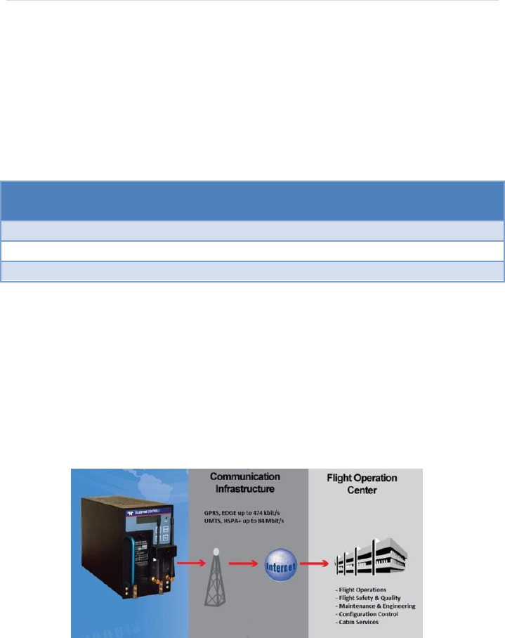
Figure 2 – Wireless GroundLink Communication Diagram ............................... 6
Figure 3 – WQAR Front Panel ....................................................................... 153
Figure 4 – WQAR Display (Run Control Enabled) .......................................... 164
Figure 5 – WQAR Display (Non-Run Control Enabled) .................................. 164
Figure 6 – WQAR Display (Data out of Sync)................................................. 164
Figure 7 – WQAR Display (Data In Sync) ....................................................... 164
Figure 8 – Behind the Access Door ............................................................... 197

P a g e | vi
Use and disclosure shall be in accordance with the proprietary legend and DCS located on page i.
UG2243800-300 Sep 16, 2013
Revised Nov 12, 2013
Definitions
3G 3rd Generation Cellular Protocol
A/C Aircraft
ACMS Aircraft Condition Monitoring System
AMI Airline Modifiable Items
ARINC Aeronautical Radio
Incorporated
DFDAU Digital Flight Data Acquisition Unit
DOD Download On Demand
eADL enhanced Airborne Data Loader
FDIMU Flight Data Interface Management Unit
OPC Operation Program Configuration
OPS Operation Program Software
QAR Quick Access Recorder
RCD Recording Completion Delay
RF Radio Frequency
TMI Teledyne Modifiable Items
UTC Universal Time, Coordinated
WGCM Wireless GroundLink® Ground Communication Manager
WPS Words per Second
WQAR Wireless GroundLink® -- Quick Access Recorder
P a g e | 7
Use and disclosure shall be in accordance with the proprietary legend and DCS located on page i.
UG2243800-300 Sep 16, 2013
Revised Nov 12, 2013
Section 1 – General
Introduction
The Teledyne Controls new Wireless GroundLink® Quick Access Recorder
(WQAR), also known as the WQAR, is the latest addition to the QAR family of
products (Figure 1). This compatible replacement for any QAR provides
convenient access to airborne data by transmitting it over a high-speed
cellular connection. It can receive flight data from any acquisition unit that is
ARINC 717 compliant. The front panel display gives status while the buttons
allow the operator to perform testing as well as view the configuration of the
unit.
Figure 1 – Wireless GroundLink Quick Access Recorder (WQAR)
P a g e | 8
Use and disclosure shall be in accordance with the proprietary legend and DCS located on page i.
UG2243800-300 Sep 16, 2013
Revised Nov 12, 2013
Scope of this document
This user’s guide describes the functions of the WQAR (P/N 2243800-36X)
using the BOOT and OPS software (P/N 711745), version D. Sections in this
guide include System Overview, Operations, Common Procedures, Fault
Procedures, and other reference information.
The hardware variants in this WQAR family are listed below:
Part Number
Connector
Type
Description
2243800-360
ARINC600
No Radios installed
2243800-362
ARINC600
Two radios with two antennae
2243800-364
ARINC600
Four radios with two antennae
For information on Teledyne Controls’ WQAR (P/N 2243800-XX), refer to OG2243800.
WQAR Operation Overview
The primary purpose of the WQAR is to record and store flight data provided
to it by a data acquisition unit such as a DFDAU or FDIMU. Then, while the
aircraft is on the ground, it wirelessly transmits that data to a base station
using high-speed 3G/4G cellular technology (where available). A backup copy
of your data is stored on a removable Compact Flash (CF) card where it sits
encrypted to ensure the safety of your data.
Figure 2 – Wireless GroundLink Communication Diagram

P a g e | 9
Use and disclosure shall be in accordance with the proprietary legend and DCS located on page i.
UG2243800-300 Sep 16, 2013
Revised Nov 12, 2013
Aircraft Signaling
The WQAR supports two different aircraft signaling types with their
accompanying speeds:
BI-POLAR: In addition to the standard hard-coded 64, 128,
256, 384,512, 1024, and 2048 WPS rates, the WQAR
supports AUTO mode where it dynamically determines the
rate of the signal as it is coming in. It also supports a
DISCRETE mode where, during bootup, it determines the
speed by monitoring speed discretes activated from the
acquisition unit.
BI-PHASE: In addition to the standard hard-coded 64, 128,
256, 384, 512, 1024, and 2048 WPS rates, the WQAR
supports AUTO mode where it dynamically determines the
rate of the signal as it is coming in. It also supports a
DISCRETE mode where, during boot up, it determines the
speed by monitoring speed discretes activated from the
acquisition unit.
If the WQAR is moved between multiple aircraft where both BI-PHASE and BI-
POLAR are used alternatively, the signal mode can be put into DISCRETE
mode where, during bootup, it monitors the BI-PHASE SELECT discrete. If this
discrete is active, the WQAR will set itself to BI-PHASE. If this discrete is not
active or not present in the aircraft, the WQAR will set itself to BI-POLAR.
After determining the signal, it will determine the speed of the signal using
the methods described above.
ACMS Reporting
In addition to the standard ARINC717 flight data, the WQAR can also record
ARINC429 data (ACMS reports) if the acquisition unit sends such reports.
When enabled, upon landing, the WQAR will power up the radios but wait a

P a g e | 10
Use and disclosure shall be in accordance with the proprietary legend and DCS located on page i.
UG2243800-300 Sep 16, 2013
Revised Nov 12, 2013
fixed amount of time before sending any data to allow for these reports to
come in. This delay is referred to as the Recording Completion Delay (RCD)
and can be set to any length. The typical setting is five minutes. Once the
RCD has elapsed, the WQAR will send both the ARINC717 and ARINC429 data
in a single file.
RF Interlocks
Aircraft regulations prohibit the WQAR radios from transmitting while the
aircraft is in the air. To comply with this regulation, Teledyne Controls has
incorporated hardware, referred to as RF Interlocks, which provides strict
controls to allow power to be applied to the radios only while the aircraft is
on the ground.
Mobile Networks
The WQAR transmits data utilizing the 3G/4G networks all over the world,
including Korea and Japan, by dynamically determining the cellular
frequencies wherever the aircraft is located.
The SIM cards used inside the WQAR are installed on a Removable SIM
Module should the customer wish to use a different cellular provider.
Download on Demand (DOD)
While most customers prefer the WQAR to transmit data in their home
network, during a flight emergency or other situation, they might find it
necessary to transmit while the aircraft is outside their home network.
Download on Demand enables the customer to direct the WQAR to override
all restrictions and transmit during these situations. If that data is ever
needed, customers can send a DOD command to the WQAR using their Base
Station. As soon as the WQAR receives this message, all accumulated flight
data will be sent back to the Base Station immediately.
P a g e | 11
Use and disclosure shall be in accordance with the proprietary legend and DCS located on page i.
UG2243800-300 Sep 16, 2013
Revised Nov 12, 2013
Run Control
Run Control is a feature in the WQAR that prevents extraneous or non-
essential data from being recorded. Typically, the WQAR will record all data
sent to it by the Acquisition Unit. However, some aircraft manufacturers
(such as Airbus) or other Acquisition Unit manufacturers require the WQAR
to record only when commanded by the Acquisition Unit. With the
appropriate aircraft wiring in place, the Acquisition Unit can command the
WQAR to record. This concept is called Run Control.
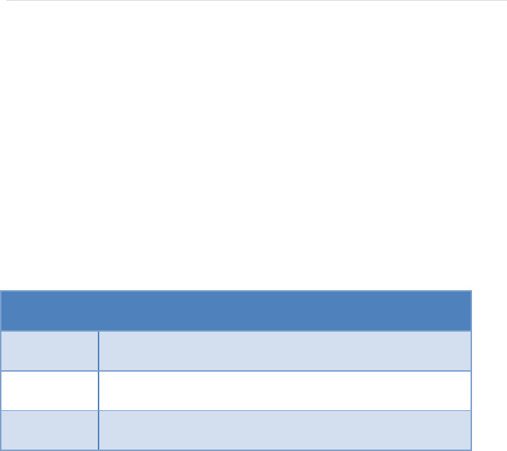
When this feature is enabled, the WQAR will show Run Control status on the
front panel display (See Section 3). The WQAR can be set to one of three
modes:
Run Control
Mode
Description
0
Run Control Feature is not used. Flight Data is recorded
at all times.
1
Run Control Feature is used. Flight Data is recorded
when commanded by the Acquisition Unit.
2
Run Control Feature is used (Record in Air). Flight Data
is recorded only when the RF Interlocks are engaged.
This mode is enabled by a setting in the configuration files (OPC).

P a g e | 12
Use and disclosure shall be in accordance with the proprietary legend and DCS located on page i.
UG2243800-300 Sep 16, 2013
Revised Nov 12, 2013
Section 2 – System Overview
Boot up and Pre-Flight Operations
Upon cold start, the WQAR FAIL light will blink slowly while it performs self-
diagnostic tests. The FAIL light will blink quickly as the OPS software boots,
determines the signal and speed of the incoming flight data, and adapts itself
to the aircraft and cellular environment. During this time, the output FAIL
discrete will not be set. After boot up is complete, the FAIL light will
extinguish and the display will momentarily show STARTUP BIT COMPLETE
followed by the normal SYSTEM STATE display as shown in Section 3 which
indicates the WQAR is ready for operation. The boot up process takes
approximately two minutes.
In-Flight Operations
Just prior to take-off, the WQAR will begin recording all incoming ARINC 717
and report data from the acquisition unit into internal memory. During flight,
the data will be periodically compressed to ready it for transmission. An
encrypted copy is also saved onto the removable CF card (P/N 2234641-008).
Post Flight Operations
Upon landing, the RF Interlocks will disengage and the radio(s) will power on
and make contact with the Wireless Ground Communication Manager
(WGCM). However, if the optional Recording Completion Delay (RCD) is
enabled, flight data will not transmit until the RCD has expired (See Section 1,
ACMS Reporting, for details). During this delay, the WQAR will continue to
receive final airborne data and ACMS reports (if present) and insert that into
the compressed file for that flight and close the file. If the WQAR determines
that it is permitted to transmit at the current destination, it will send the
flight data to the WGCM. If not, at the next destination, it will make the
determination again. It will continue to do all of the above at every

P a g e | 13
Use and disclosure shall be in accordance with the proprietary legend and DCS located on page i.
UG2243800-300 Sep 16, 2013
Revised Nov 12, 2013
destination until the aircraft arrives in a permitted cellular network where it
will transmit all accumulated data. If a transmission is interrupted for any
reason, the WQAR does not need to re-transmit from the beginning. It has
the ability to resume from the point of interruption. The radios will remain
powered on while the aircraft is on the ground whether transmissions occur
or not. If the Download on Demand (DOD) feature is enabled, the WQAR will
accept any DOD messages if they are sent. See Section I for an overview on
this feature. Contact Teledyne Controls Customer Services for more
information.
If the cellular radios cannot transmit for any reason, data can still be
retrieved by ejecting the compact flash (CF) card using the procedure in
Section 4. See Section 5 for specific details.
Upgrading and Configuring Your WQAR
Only the aircraft tail number can be changed via the front panel buttons.
However, the Radios can be disabled and the Run Control mode can be
overridden via the front panel. These changes will persist through power
cycling.
In general, there are two software components in the WQAR: The OPS
(software) and OPC files (configuration files). The OPS and OPC files are
ARINC 665 Loadable Software Parts (LSPs).
The OPS, which runs on the WQAR, can be upgraded using the procedures
found in Service Bulletins provided by Teledyne Controls. Contact Teledyne
Controls Customer Services for details.
P a g e | 14
Use and disclosure shall be in accordance with the proprietary legend and DCS located on page i.
UG2243800-300 Sep 16, 2013
Revised Nov 12, 2013
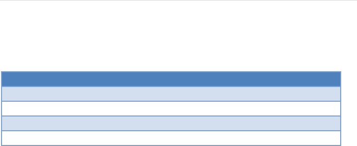
The OPC LSPs, which contain parameters, configure the WQAR to adapt it to
your aircraft and cellular environment. These LSPs, customized for each
operator, are installed in every WQAR at the factory and are listed below.
LSP
Description
Customer Modifiable
AII
Aircraft Interface Items
No
AMI
Airline Modifiable Items
Yes
TMI
Teledyne Modifiable Items
No
Switch
Switch Configuration Items
No
P a g e | 15
Use and disclosure shall be in accordance with the proprietary legend and DCS located on page i.
UG2243800-300 Sep 16, 2013
Revised Nov 12, 2013
Section 3 – WQAR Operations
Front Panel
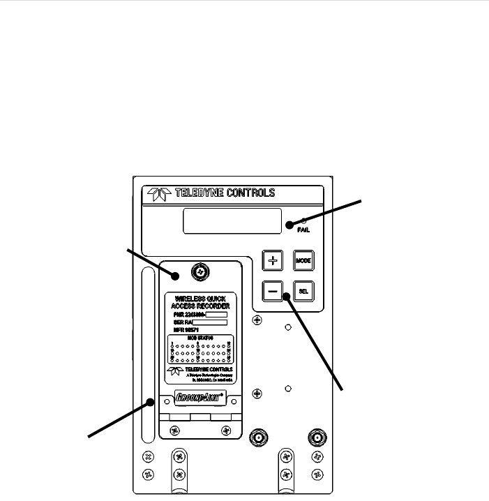
The WQAR has a front panel interface to allow the operator to check status
as well as perform diagnostics and other maintenance activity (Figure 3).
Antennae have been removed for clarity in Figure 3.
Figure 3 – WQAR Front Panel
Front Panel Display
The blue backlit front panel display has two lines with 16 characters each and
shows the status of the unit. The top line displays the general status of the
unit including failure status. Figures 4 and 5 shows normal post-boot-up
Access Door
Handle
Front Panel
Buttons
Front Panel
Display
P a g e | 16
Use and disclosure shall be in accordance with the proprietary legend and DCS located on page i.
UG2243800-300 Sep 16, 2013
Revised Nov 12, 2013
status for Run-Control enabled aircraft (usually Airbus) and Non-Run-Control
enabled aircraft (usually Boeing and others).
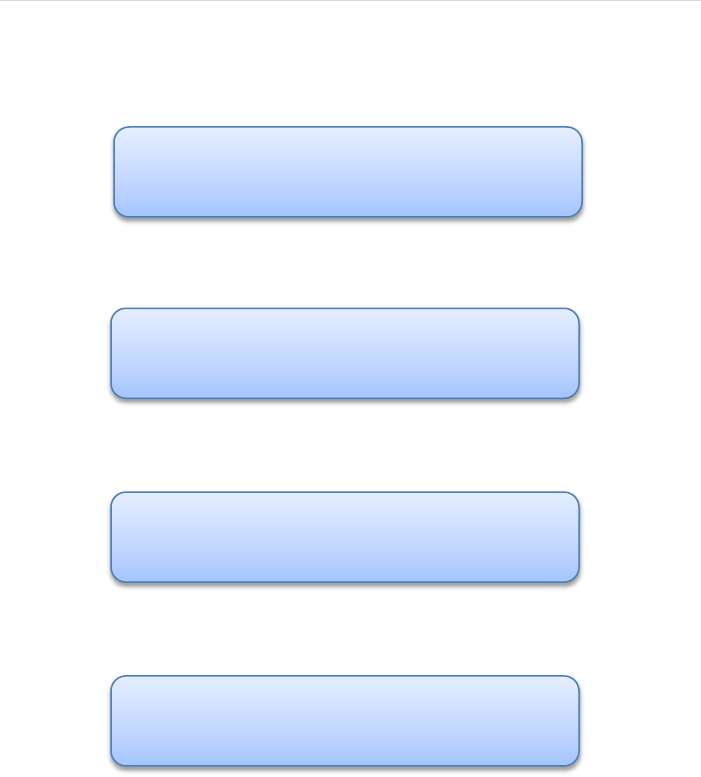
Figure 4 – WQAR Display (Run Control Enabled)
Figure 5 – WQAR Display (Non-Run Control Enabled)
Figure 6 – WQAR Display (Data out of Sync)
Figure 7 – WQAR Display (Data In Sync)
Figures 6 and 7 show an example of the display when flight data is coming in
when it is out-of-sync and in-sync respectively. In addition, Figure 7 indicates
that the WQAR has recorded ACMS report(s) by displaying “Msg”.
RUN DISABLED
R_On : :Ioff
R_On : :Ioff
RawIn:NoSync
R_On : :Ioff
RawIn:SyncIn:Msg
R_On : :Ioff

P a g e | 17
Use and disclosure shall be in accordance with the proprietary legend and DCS located on page i.
UG2243800-300 Sep 16, 2013
Revised Nov 12, 2013
The bottom line has three sections separated by colons (:) which indicate the
status of hardware inside the WQAR:
Left Section: Monitors the status of the cellular radios by
displaying whether power is applied to the radios and the
connection status.
R_On: Radio(s) are powered on. This is the default
state while the aircraft is on the ground.
R_Off: Radio(s) are powered off.
CON: Connected. The WQAR has achieved a
connection with the WGCM. “NO_CON” may be
displayed if a connection attempt fails.
DN: Downloading. The WQAR is currently downloading
data to the base station.
UP: Uploading. The WQAR is currently uploading data
from the base station.
Middle Section: Monitors the status of the airborne data
files such as whether the files are ready for transmission.
RDY: Ready. The WQAR has met the minimum raw
data requirements to transmit data.
RCD: Recording Completion Delay. The WQAR is
waiting for any final data from the acquisition unit
before performing final compression and closing of the
data file.
CMP: Compression. The WQAR is actively compressing
data at this time.
<Blank>: The WQAR is not in any of the above states.
Right Section: Monitors the status of the RF Interlocks. A
discussion of the RF interlocks is in Section 1. In Figures 4
and 5, the RF Interlocks are shown to be off.
P a g e | 18
Use and disclosure shall be in accordance with the proprietary legend and DCS located on page i.
UG2243800-300 Sep 16, 2013
Revised Nov 12, 2013
Ion: Interlocks are engaged. The radios are restricted
from receiving power.
Ioff: Interlocks are not engaged. The radios are no
longer restricted from receiving power.
FAIL Indicator
The WQAR is equipped with an amber-colored FAIL indicator which will
illuminate whenever a hardware fault is detected, configuration files are
missing, or if the internal flight data card is full. The FAIL discrete will usually
(but not always) be activated whenever the FAIL indicator is illuminated.
Front Panel Buttons
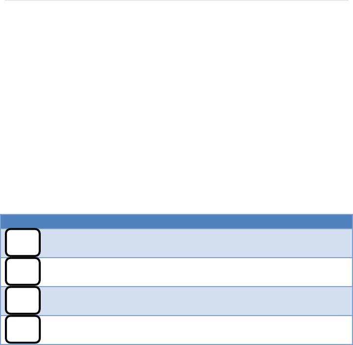
There are four buttons on the front panel:
Button
Description
This button is used to exit out of the current menu or to escape
certain functions in process.
The SELECT button is used to enter into the selected menu. It is
also used to choose or confirm any changes made to the LRU.
The + (PLUS) button is used to advance though the various
menus and parameters.
The – (MINUS) button is used to reverse though the various
menus and parameters.
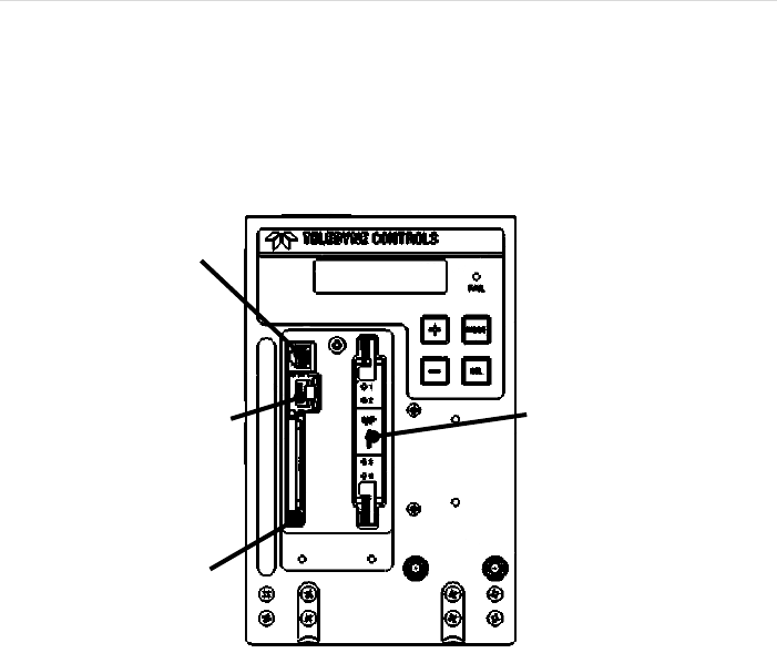
Access Door
The outside of the access door has the label which displays the Part Number,
Serial Number, and MOD Status. The door, which swings down, can be
opened by rotating the thumbscrew counter-clockwise. Behind the door are
the Removable SIM Module (RSM), the Compact Flash (CF) Recording Media,
the RJ-45 port, and the RS-232 Console Port. The CF Recording Media (P/N
MODE
SEL
+
-
P a g e | 19
Use and disclosure shall be in accordance with the proprietary legend and DCS located on page i.
UG2243800-300 Sep 16, 2013
Revised Nov 12, 2013
2234641-008) contains encrypted backup flight data and system log file. The
Removable SIM Module can hold up to four SIM cards, one for each of the
four cellular radios inside the LRU. Maintenance procedures for the
Removable SIM Module and CF cards are in Section 4.
Figure 8 – Behind the Access Door
Antennae
There are two antennae connected to elbow connectors at the front of the
unit and are secured in place with a bumper to discourage handling. They
can be replaced using the appropriate procedure. Contact Teledyne Controls
Sales Department for replacement parts. The antenna replacement
procedure will be in a Service Bulletin.
CF Card
Ejection Button
RJ-45 Port
(ARINC 615A Data
Loader Port)
RJ-11 Console
Port
Removable
SIM Module

P a g e | 20
Use and disclosure shall be in accordance with the proprietary legend and DCS located on page i.
UG2243800-300 Sep 16, 2013
Revised Nov 12, 2013
Date/Time
The WQAR has a system clock (UTC) and is set at the factory using the front
panel System Menus. The clock’s power source is a super-capacitor inside
the WQAR which lasts approximately 30 days. The clock will lose its time if it
doesn’t have access to aircraft power for that length of time. The WQAR
does not use the Captain’s clock to refresh the clock. However, if configured,
the WQAR will update the clock whenever it connects to the Wireless
Groundlink Communication Manager. This time update takes up to
approximately five minutes and the FAIL light will blink during this time and
the unit will reboot. After reboot, the WQAR will be operational with the
proper time.
System Menus
The WQAR menus are accessed using the Front Panel Buttons and are viewed
in the Front Panel Display. After bootup, the unit defaults to the SYSTEM
STATE menu which displays the system status as shown in Figures 4 and 5. If
the WQAR buttons experience no activity for 30 minutes for top-level menus
and 10 minutes for sub-menus, the WQAR automatically returns to this
menu.
Entering and Exiting Menus
To exit any menu, including the SYSTEM STATE menu, press the MODE
button. To enter any menu, including the SYSTEM STATE menu, press the SEL
button. After viewing any menu, it is always good practice to return to the
SYSTEM STATE menu.