Teledyne 200Ah Users Manual INSTRUCTION NITROGEN OXIDES ANALYZER
200AH to the manual 9f4a59fd-de5a-49df-ae9f-46d2812afb7a
2015-02-03
: Teledyne Teledyne-200Ah-Users-Manual-464569 teledyne-200ah-users-manual-464569 teledyne pdf
Open the PDF directly: View PDF ![]() .
.
Page Count: 196 [warning: Documents this large are best viewed by clicking the View PDF Link!]
- INSTRUCTION MANUAL MODEL 200AH NITROGEN OXIDES ANALYZER
- SAFETY MESSAGES
- LIST OF TABLES
- 1. HOW TO USE THIS MANUAL
- 2. GETTING STARTED
- 3. SPECIFICATIONS, WARRANTY
- 4. THE M200AH NOX ANALYZER
- 4.1. Principle of Operation
- 4.2. Operation Summary
- 5. SOFTWARE FEATURES
- 5.1. Index to Front Panel Menus
- 5.2. Sample Mode
- 5.3. Set-Up Mode
- 5.4. M200AH Operating Modes
- 5.5. 4-20 mA Current Loop
- 5.6. Status Output
- 5.7. RS-232 Interface
- 6. OPTIONAL HARDWARE AND SOFTWARE
- 7. CALIBRATION AND ZERO/SPAN CHECKS
- 7.1. Manual NOX Zero/Span Check or Cal With Zero/Span Gas in the Sample Port
- 7.2. Manual O2 Zero/Span Check or Cal With Zero/Span Gas in the Sample Port
- 7.3. Manual Zero/Span Check with Zero/Span Valves Option
- 7.4. Dynamic Zero/Span Calibration Using AutoCal
- 7.5. Use of Zero/Span Valves with Remote Contact Closure
- 7.6. NO Only Mode Calibration
- 7.7. NOX Only Mode Calibration
- 7.8. Calibration Requirements for AutoRange or Remote Range
- 7.9. Calibration Requirements for Independent Range
- 7.10. Calibration Quality
- 7.11. Converter Efficiency Compensation
- 7.12. Recommendations for CEM Applications
- 8. MAINTENANCE
- 9. TROUBLESHOOTING AND ADJUSTMENTS
- 9.1. Operation Verification - Diagnostic Techniques
- 9.2. Performance Problems
- 9.2.1. AC Power Check
- 9.2.2. Flow Check
- 9.2.3. No Response to Sample Gas
- 9.2.4. Negative Output
- 9.2.5. Excessive Noise
- 9.2.6. Unstable Span
- 9.2.7. Unstable Zero
- 9.2.8. Inability to Span
- 9.2.9. Inability to Zero
- 9.2.10. Non-Linear Response
- 9.2.11. Slow Response
- 9.2.12. Analog Output Doesn't Agree With Display Concentration
- 9.3. Subsystem Troubleshooting and Adjustments
- APPENDICES

INSTRUCTION MANUAL
MODEL 200AH
NITROGEN OXIDES ANALYZER
©TELEDYNE INSTRUMENTS
ADVANCED POLLUTION INSTRUMENTATION DIVISION
(T-API)
9480 CARROLL PARK DRIVE
SAN DIEGO, CA 92121-5201
TOLL-FREE: 800-324-5190
FAX: 858-657-9816
TEL: 858-657-9800
E-MAIL: api-sales@teledyne.com
WEB SITE: www.teledyne-api.com
01620 REV. G2
DCN 5333
Copyright 2006 T-API Inc. 03 March 2009
PRINT DATE: 03 March 2009
THIS PAGE IS INTENTIONALLY LEFT BLANK
Teledyne API Model 200AH NOX Analyzer Instruction Manual, 06492, Rev. G2
i
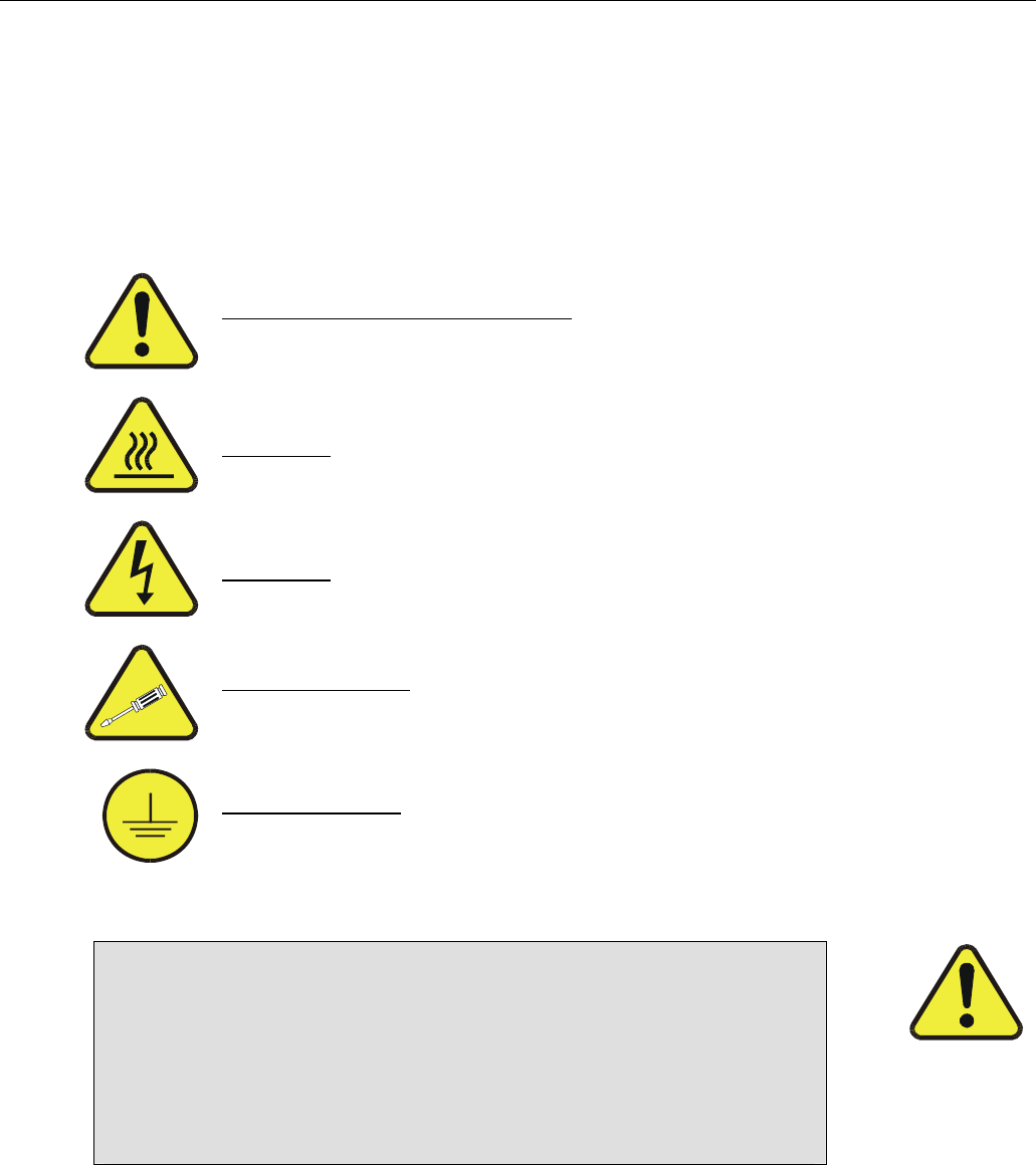
SAFETY MESSAGES
Your safety and the safety of others is very important. We have provided many important safety messages
in this manual. Please read these messages carefully.
A safety message alerts you to potential hazards that could hurt you or others. Each safety message is
associated with a safety alert symbol. These symbols are found in the manual and inside the instrument.
The definition of these symbols is described below:
GENERAL WARNING/CAUTION: Refer to the instructions for details on the
specific danger.
CAUTION: Hot Surface Warning
CAUTION: Electrical Shock Hazard
Technician Symbol: All operations marked with this symbol are to be performed
by qualified maintenance personnel only.
Electrical Ground: This symbol inside the instrument marks the central safety
grounding point for the instrument.
CAUTION
The analyzer should only be used for the purpose
and in the manner described in this manual.
If you use the analyzer in a manner other than that for which
it was intended, unpredictable behavior could ensue with
possible hazardous consequences.

Teledyne API Model 200AH NOX Analyzer Instruction Manual, 06492, Rev. G2
ii
THIS PAGE IS INTENTIONALLY LEFT BLANK

Teledyne API Model 200AH NOX Analyzer Instruction Manual, 06492, Rev. G2
iii
Table of Contents
SAFETY MESSAGES ........................................................................................... I
LIST OF TABLES.............................................................................................. VIII
1. HOW TO USE THIS MANUAL...................................................................... 1-1
2. GETTING STARTED..................................................................................... 2-1
2.1. UNPACKING.................................................................................................................... 2-1
2.2. ELECTRICAL AND PNEUMATIC CONNECTIONS .................................................................... 2-1
2.3. INITIAL OPERATION ......................................................................................................... 2-7
3. SPECIFICATIONS, WARRANTY.................................................................. 3-1
3.1. SPECIFICATIONS ............................................................................................................. 3-1
3.2. WARRANTY .................................................................................................................... 3-2
4. THE M200AH NOX ANALYZER ................................................................... 4-1
4.1. PRINCIPLE OF OPERATION ............................................................................................... 4-1
4.1.1. NOX Measurement................................................................................................. 4-1
4.1.2. Oxygen Measurement (Option) ............................................................................. 4-2
4.2. OPERATION SUMMARY .................................................................................................... 4-5
4.2.1. NOX Sensor Module, Reaction Cell, Detector........................................................ 4-5
4.2.2. Oxygen Sensor Module (Option) ........................................................................... 4-5
4.2.3. Pneumatic Sensor Board....................................................................................... 4-6
4.2.4. Computer Hardware and Software ........................................................................ 4-6
4.2.5. V/F Board .............................................................................................................. 4-7
4.2.6. Front Panel............................................................................................................ 4-7
4.2.7. Power Supply Module............................................................................................ 4-8
4.2.8. Pump, Valves, Pneumatic System......................................................................... 4-8
4.2.9. Ozone Generator................................................................................................. 4-11
4.2.10. NO2 - NO Converter .......................................................................................... 4-11
5. SOFTWARE FEATURES.............................................................................. 5-1
5.1. INDEX TO FRONT PANEL MENUS....................................................................................... 5-1
5.1.1. Sample Menu ........................................................................................................ 5-6
5.1.2. Set-Up Menu ......................................................................................................... 5-7
5.2. SAMPLE MODE ............................................................................................................. 5-11
5.2.1. Test Functions..................................................................................................... 5-11
5.2.2. CAL, CALS, CALZ, Calibration Functions............................................................ 5-15
5.3. SET-UP MODE.............................................................................................................. 5-17
5.3.1. Configuration Information (CFG) ......................................................................... 5-17
5.3.2. Automatic Calibration (AutoCal) .......................................................................... 5-17
5.3.3. Data Acquisition System (DAS)........................................................................... 5-18

Teledyne API Model 200AH NOX Analyzer Instruction Manual, 06492, Rev. G2
iv
5.3.4. Range Menu........................................................................................................ 5-20
5.3.5. Password Enable................................................................................................. 5-23
5.3.6. Time of Day Clock ............................................................................................... 5-23
5.3.7. Diagnostic Mode.................................................................................................. 5-23
5.3.8. Communications Menu........................................................................................ 5-24
5.3.9. Variables Menu (VARS) ...................................................................................... 5-24
5.4. M200AH OPERATING MODES........................................................................................ 5-25
5.4.1. NO/NOx/NO2 Switching Mode.............................................................................. 5-25
5.4.2. NOX Only Mode ................................................................................................... 5-26
5.4.3. NO Only Mode..................................................................................................... 5-26
5.5. 4-20 MA CURRENT LOOP .............................................................................................. 5-27
5.6. STATUS OUTPUT........................................................................................................... 5-27
5.7. RS-232 INTERFACE ...................................................................................................... 5-28
5.7.1. Setting up the RS-232 Interface .......................................................................... 5-28
5.7.2. Command Summary............................................................................................ 5-31
5.7.3. TEST Commands and Messages........................................................................ 5-35
5.7.4. WARNING Commands and Messages................................................................ 5-36
5.7.5. CALIBRATION Commands and Messages ......................................................... 5-37
5.7.6. DIAGNOSTIC Commands and Messages........................................................... 5-38
5.7.7. DAS Commands and Messages.......................................................................... 5-39
5.7.8. VARIABLES Commands and Messages ............................................................. 5-41
6. OPTIONAL HARDWARE AND SOFTWARE................................................ 6-1
6.1. RACK MOUNT OPTIONS................................................................................................... 6-1
6.2. ZERO/SPAN VALVES OPTION ........................................................................................... 6-2
6.2.1. Autocal - Setup Zero/Span Valves......................................................................... 6-3
6.3. OXYGEN SENSOR OPTION ............................................................................................... 6-4
6.4. ISOLATED 4-20 MA CURRENT LOOP OPTION ..................................................................... 6-5
6.5. MOLYBDENUM CONVERTER OPTION ................................................................................. 6-5
6.6. EXTERNAL DESICCANT CANISTER OPTION ........................................................................ 6-5
6.7. ALTERNATE BYPASS FLOW ORIFICE OPTION ..................................................................... 6-5
6.8. M501 EXTERNAL CONVERTER OPTION............................................................................. 6-5
7. CALIBRATION AND ZERO/SPAN CHECKS ............................................... 7-1
7.1. MANUAL NOX ZERO/SPAN CHECK OR CAL WITH ZERO/SPAN GAS IN THE SAMPLE PORT...... 7-3
7.2. MANUAL O2 ZERO/SPAN CHECK OR CAL WITH ZERO/SPAN GAS IN THE SAMPLE PORT ........ 7-6
7.3. MANUAL ZERO/SPAN CHECK WITH ZERO/SPAN VALVES OPTION......................................... 7-7
7.4. DYNAMIC ZERO/SPAN CALIBRATION USING AUTOCAL........................................................ 7-9
7.5. USE OF ZERO/SPAN VALVES WITH REMOTE CONTACT CLOSURE ...................................... 7-10
7.6. NO ONLY MODE CALIBRATION....................................................................................... 7-11
7.7. NOX ONLY MODE CALIBRATION ..................................................................................... 7-11
7.8. CALIBRATION REQUIREMENTS FOR AUTORANGE OR REMOTE RANGE................................ 7-11
7.9. CALIBRATION REQUIREMENTS FOR INDEPENDENT RANGE ................................................ 7-12
7.10. CALIBRATION QUALITY ................................................................................................ 7-12
7.11. CONVERTER EFFICIENCY COMPENSATION..................................................................... 7-13
7.12. RECOMMENDATIONS FOR CEM APPLICATIONS .............................................................. 7-14

Teledyne API Model 200AH NOX Analyzer Instruction Manual, 06492, Rev. G2
v
7.12.1. Calibration Gasses ............................................................................................ 7-14
7.12.2. Calibration Frequency ....................................................................................... 7-15
7.12.3. Converter Efficiency .......................................................................................... 7-15
8. MAINTENANCE ............................................................................................ 8-1
8.1. MAINTENANCE SCHEDULE ............................................................................................... 8-1
8.2. REPLACING THE SAMPLE PARTICULATE FILTER ................................................................. 8-2
8.3. REPLACING THE CONVERTER........................................................................................... 8-4
8.4. CLEANING THE REACTION CELL ....................................................................................... 8-6
8.5. PNEUMATIC LINE INSPECTION .......................................................................................... 8-9
8.6. LEAK CHECK PROCEDURE ............................................................................................. 8-13
8.7. LIGHT LEAK CHECK PROCEDURE.................................................................................... 8-13
8.8. PROM REPLACEMENT PROCEDURE ................................................................................ 8-14
9. TROUBLESHOOTING AND ADJUSTMENTS.............................................. 9-1
9.1. OPERATION VERIFICATION - DIAGNOSTIC TECHNIQUES ...................................................... 9-2
9.1.1. Fault Diagnosis with TEST Variables .................................................................... 9-2
9.1.2. Fault Diagnosis with WARNING Messages........................................................... 9-8
9.1.3. Fault Diagnosis using DIAGNOSTIC Mode ......................................................... 9-10
9.1.4. M200AH Internal Variables.................................................................................. 9-17
9.1.5. Test Channel Analog Output ............................................................................... 9-19
9.1.6. Factory Calibration Procedure............................................................................. 9-20
9.2. PERFORMANCE PROBLEMS............................................................................................ 9-24
9.2.1. AC Power Check ................................................................................................. 9-24
9.2.2. Flow Check.......................................................................................................... 9-25
9.2.3. No Response to Sample Gas .............................................................................. 9-25
9.2.4. Negative Output................................................................................................... 9-26
9.2.5. Excessive Noise .................................................................................................. 9-26
9.2.6. Unstable Span..................................................................................................... 9-27
9.2.7. Unstable Zero...................................................................................................... 9-28
9.2.8. Inability to Span................................................................................................... 9-28
9.2.9. Inability to Zero.................................................................................................... 9-28
9.2.10. Non-Linear Response........................................................................................ 9-29
9.2.11. Slow Response.................................................................................................. 9-30
9.2.12. Analog Output Doesn't Agree With Display Concentration................................ 9-30
9.3. SUBSYSTEM TROUBLESHOOTING AND ADJUSTMENTS....................................................... 9-31
9.3.1. Computer, Display, Keyboard.............................................................................. 9-31
9.3.2. RS-232 Communications..................................................................................... 9-34
9.3.3. Voltage/Frequency (V/F) Board........................................................................... 9-37
9.3.4. Status/Temp Board.............................................................................................. 9-43
9.3.5. Power Supply Module.......................................................................................... 9-45
9.3.6. Ozone Generator................................................................................................. 9-49
9.3.7. Flow/Pressure Sensor ......................................................................................... 9-53
9.3.8. NOX Sensor Module ............................................................................................ 9-58
9.3.9. Z/S Valves ........................................................................................................... 9-63
9.3.10. Pneumatic System............................................................................................. 9-64


Teledyne API Model 200AH NOX Analyzer Instruction Manual, 06492, Rev. G2
vii
LIST OF FIGURES
FIGURE 2-1: REMOVAL OF SHIPPING SCREWS & CHECK FOR CORRECT POWER ............................ 2-3
FIGURE 2-2: REAR PANEL ......................................................................................................... 2-4
FIGURE 2-3: REAR PANEL WITH O2 OPTION................................................................................ 2-5
FIGURE 2-4: INLET AND EXHAUST VENTING RECOMMENDATIONS.................................................. 2-6
FIGURE 2-5: FRONT PANEL ..................................................................................................... 2-12
FIGURE 2-6: ASSEMBLY LAYOUT.............................................................................................. 2-13
FIGURE 2-7: ASSEMBLY LAYOUT – O2 SENSOR OPTION............................................................. 2-14
FIGURE 4-1: PARAMAGNETIC SENSOR........................................................................................ 4-3
FIGURE 4-2: BLOCK DIAGRAM ................................................................................................... 4-4
FIGURE 4-3: EXTERNAL PUMP PACK ........................................................................................ 4-10
FIGURE 5-1: SAMPLE MENU TREE ............................................................................................. 5-2
FIGURE 5-2: SETUP MENU TREE ............................................................................................... 5-3
FIGURE 5-3: SETUP MENU TREE- UNITS WITH O2 SENSOR .......................................................... 5-4
FIGURE 5-4: SETUP MENU TREE – UNITS WITH O2 SENSOR......................................................... 5-5
FIGURE 8-1: REPLACING THE PARTICULATE FILTER..................................................................... 8-3
FIGURE 8-2: CONVERTER ASSEMBLY ......................................................................................... 8-5
FIGURE 8-3: REACTION CELL ASSEMBLY.................................................................................... 8-7
FIGURE 8-4: SAMPLE/BYPASS FLOW CONTROL ASSEMBLY .......................................................... 8-8
FIGURE 8-5: PNEUMATIC DIAGRAM .......................................................................................... 8-10
FIGURE 8-6: PNEUMATIC DIAGRAM WITH ZERO/SPAN VALVES.................................................... 8-11
FIGURE 8-7: PNEUMATIC DIAGRAM WITH OXYGEN SENSOR........................................................ 8-12
FIGURE 9-1: SPAN CALIBRATION VOLTAGE............................................................................... 9-23
FIGURE 9-2: CPU BOARD JUMPER SETTINGS........................................................................... 9-33
FIGURE 9-3: RS-232 PIN ASSIGNMENTS.................................................................................. 9-35
FIGURE 9-4: V/F BOARD JUMPER SETTINGS............................................................................. 9-42
FIGURE 9-5: POWER SUPPLY MODULE LAYOUT ........................................................................ 9-47
FIGURE 9-6: ELECTRICAL BLOCK DIAGRAM............................................................................... 9-48
FIGURE 9-7: OZONE GENERATOR SUBSYSTEM ......................................................................... 9-52
FIGURE 9-8: FLOW/PRESSURE SENSOR ................................................................................... 9-55
FIGURE 9-9: NOX SENSOR MODULE ........................................................................................ 9-56
FIGURE 9-10: NOX SENSOR MODULE ...................................................................................... 9-57
FIGURE 9-11: PMT COOLER SUBSYSTEM ................................................................................ 9-60
FIGURE 9-12: HIGH VOLTAGE POWER SUPPLY ......................................................................... 9-62

Teledyne API Model 200AH NOX Analyzer Instruction Manual, 06492, Rev. G2
viii
LIST OF TABLES
TABLE 2-1: FINAL TEST AND CALIBRATION VALUES ................................................................... 2-15
TABLE 4-1: SAMPLING MODES OF THE M200AH......................................................................... 4-1
TABLE 4-2: FRONT PANEL STATUS LED'S.................................................................................. 4-8
TABLE 4-3: OZONE GENERATOR START-UP TIMING................................................................... 4-11
TABLE 5-1: M200AH SAMPLE MENU STRUCTURE....................................................................... 5-6
TABLE 5-2: M200AH SETUP MENU ........................................................................................... 5-7
TABLE 5-3: M200AH SETUP MENU ........................................................................................... 5-9
TABLE 5-4: M200AH SETUP MENU ......................................................................................... 5-10
TABLE 5-5: DAS DATA CHANNEL EDITING................................................................................ 5-19
TABLE 5-6: CALIBRATE, SETUP PASSWORDS ............................................................................ 5-23
TABLE 5-7: M200AH OPERATING MODES ................................................................................ 5-25
TABLE 5-8: STATUS OUTPUT PIN ASSIGNMENTS ....................................................................... 5-27
TABLE 5-9: RS-232 PORT SETUP - FRONT PANEL .................................................................... 5-29
TABLE 5-10: RS-232 SWITCHING FROM TERMINAL MODE TO COMPUTER MODE ......................... 5-30
TABLE 5-11: RS-232 TERMINAL MODE EDITING KEYS............................................................... 5-31
TABLE 5-12: RS-232 COMMAND SUMMARY.............................................................................. 5-32
TABLE 5-13: RS-232 COMMAND SUMMARY.............................................................................. 5-33
TABLE 5-14: RS-232 INTERFACE COMMAND TYPES.................................................................. 5-34
TABLE 5-15: RS-232 TEST MESSAGES.................................................................................... 5-35
TABLE 5-16: RS-232 WARNING MESSAGES ............................................................................. 5-36
TABLE 5-17: RS-232 CALIBRATION MESSAGES ........................................................................ 5-37
TABLE 5-18: RS-232 CALIBRATION COMMANDS ....................................................................... 5-38
TABLE 5-19: RS-232 DIAGNOSTIC COMMAND SUMMARY........................................................... 5-39
TABLE 6-1: ZERO/SPAN VALVE OPERATION................................................................................ 6-2
TABLE 6-2: SETUP AUTOMATIC ZERO/SPAN CHECKING OR CALIBRATION ...................................... 6-3
TABLE 6-3: ACTION OF MODE FIELD IN AUTOCAL ...................................................................... 6-4
TABLE 7-1: TYPES OF ZERO/SPAN CHECK AND CALIBRATION....................................................... 7-2
TABLE 7-2: MANUAL ZERO CALIBRATION PROCEDURE - ZERO GAS THRU SAMPLE PORT ............... 7-3
TABLE 7-3: ENTER EXPECTED SPAN GAS CONCENTRATIONS PROCEDURE.................................... 7-4
TABLE 7-4: MANUAL SPAN CALIBRATION PROCEDURE - SPAN GAS THRU SAMPLE PORT................ 7-5
TABLE 7-5: MANUAL O2 ZERO CALIBRATION PROCEDURE - ZERO GAS THRU SAMPLE PORT........... 7-6
TABLE 7-6: MANUAL O2 SPAN CALIBRATION PROCEDURE - SPAN GAS THRU SAMPLE PORT........... 7-7
TABLE 7-7: MANUAL ZERO CHECK PROCEDURE - Z/S VALVES ..................................................... 7-8
TABLE 7-8: MANUAL SPAN CHECK PROCEDURE - Z/S VALVES ..................................................... 7-9
TABLE 7-9: Z/S VALVE MODES WITH REMOTE CONTACT CLOSURE............................................. 7-10
TABLE 7-10: CALIBRATION REQUIREMENTS FOR AUTORANGE OR REMOTE RANGE ...................... 7-12
TABLE 7-11: CALIBRATION QUALITY CHECK.............................................................................. 7-13
TABLE 7-12: CONVERTER EFFICIENCY - AUTOMATIC CALCULATION ............................................ 7-14
TABLE 8-1: PREVENTATIVE MAINTENANCE SCHEDULE ................................................................. 8-1
TABLE 9-1: TEST FUNCTIONS .................................................................................................... 9-3
TABLE 9-2: FRONT PANEL WARNING MESSAGES......................................................................... 9-9
TABLE 9-3: SUMMARY OF DIAGNOSTIC MODES ......................................................................... 9-11

Teledyne API Model 200AH NOX Analyzer Instruction Manual, 06492, Rev. G2
ix
TABLE 9-4: DIAGNOSTIC MODE - SIGNAL I/O ............................................................................ 9-12
TABLE 9-5: MODEL 200AH VARIABLES .................................................................................... 9-18
TABLE 9-6: TEST CHANNEL READINGS ..................................................................................... 9-19
TABLE 9-7: MOTHERBOARD JUMPER SETTINGS......................................................................... 9-39
TABLE 9-8: V/F BOARD SWITCH SETTINGS............................................................................... 9-39
TABLE 9-9: POWER SUPPLY MODULE SUBASSEMBLIES.............................................................. 9-46
TABLE 9-10: POWER SUPPLY MODULE LED OPERATION........................................................... 9-49
TABLE 9-11: OZONE GENERATOR CONTROL CONDITIONS.......................................................... 9-50

Teledyne API Model 200AH NOX Analyzer Instruction Manual, 06492, Rev. G2
x
THIS PAGE IS INTENTIONALLY LEFT BLANK

Teledyne API Model 200AH NOX Analyzer Instruction Manual, 06492, Rev. G2
1-1
1. HOW TO USE THIS MANUAL
The Model 200AH has been designed to produce accurate data, be serviceable, reliable and easy
to use. The M200AH's microprocessor continually checks operating parameters such as
temperature, flow, and critical voltages. The instruments design uses top mounted, modular
components with captive screws to facilitate repair and ease of access. If you encounter any
difficulty refer to the Troubleshooting Section 9 - General Hints.
We recognize that the need for information from this manual changes as time passes. When the
instrument first arrives, it is necessary to get it up and running quickly and verify its correct
operation. As time passes, more detailed information is often required on special configurations,
calibration alternatives and other operational details. Finally there is the need for periodic
maintenance and to quickly troubleshoot problems to assure maximum reliability and data
integrity.
To address these needs, we have created three indexes to the information inside. They are:
Table of Contents:
Outlines the contents of the manual in the order the information is presented. This is a good
overview of the topics covered in the manual. There is also a list of Tables and a list of Figures.
Index to M200AH Front Panel Menus:
The Menu Index briefly describes the front panel menus and refers you to other sections of the
manual that have a detailed explanation of each menu selection.
Troubleshooting Section 9:
The Troubleshooting Section allows you to diagnose and repair the instrument based on
variables in the TEST menu, the results of DIAGNOSTIC tests, and performance faults such as
excessive noise or drift. The troubleshooting section also explains the operation, adjustment,
diagnosis and testing of each instrument subsystem.
If you are unpacking the instrument for the first time, please refer to Getting Started in
Section 2.

Teledyne API Model 200AH NOX Analyzer Instruction Manual, 06492, Rev. G2
1-2
THIS PAGE IS INTENTIONALLY LEFT BLANK

Teledyne API Model 200AH NOX Analyzer Instruction Manual, 06492, Rev. G2
2-1
2. GETTING STARTED
2.1. Unpacking
CAUTION
Your safety and the safety of others is very important. We
have provided many important safety messages in this manual.
Please read these messages carefully.
To avoid personal injury, always use two persons to
lift and carry the Model 200AH.
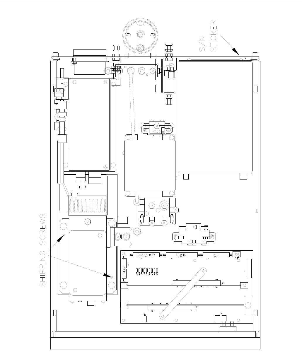
1. Before operation it is necessary to remove the shipping hold-down screws. Remove the
instrument cover, then remove 2 screws as shown in Figure 2-1.
2. Also check for internal shipping damage, and generally inspect the interior of the instrument
to make sure all circuit boards and other components are in good shape.
3. Please check the voltage and frequency label on the serial number tag on the rear panel.
Compare that to your local power before plugging in the Instrument.
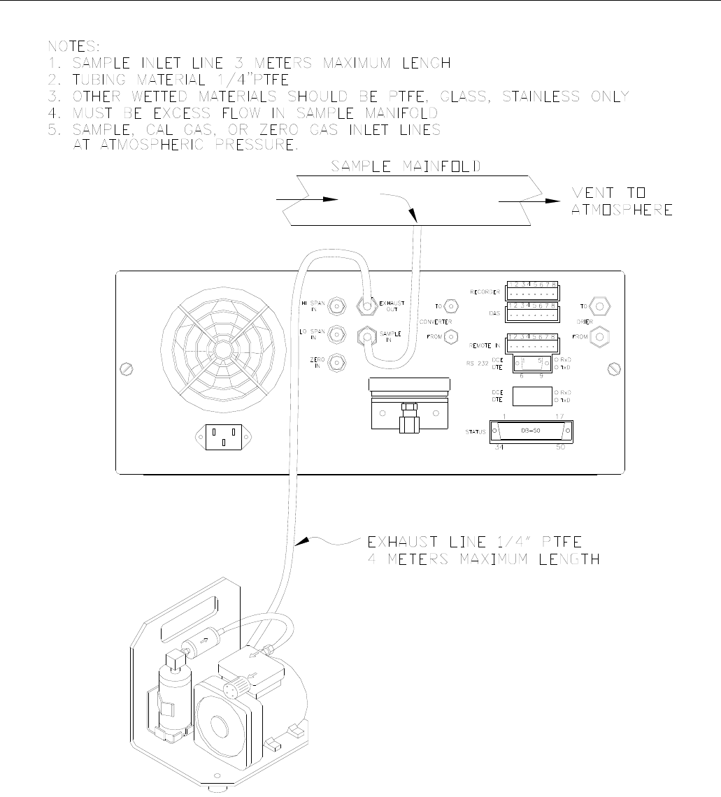
2.2. Electrical and Pneumatic Connections
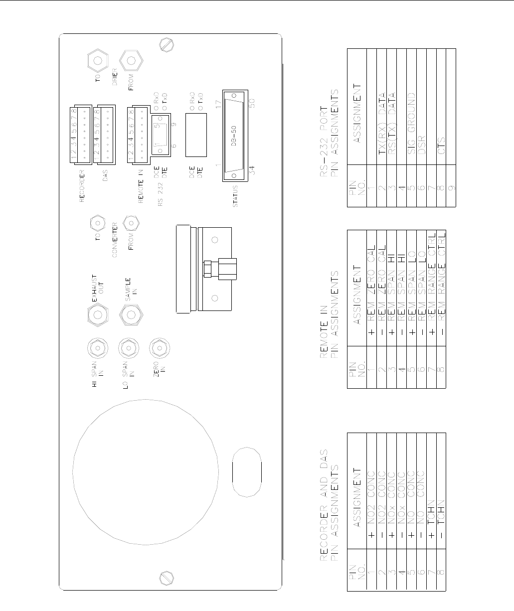
1. Refer to Figure 2-2 to locate the rear panel electrical and pneumatic connections.
2. Attach the pump to the “Exhaust Out” port on the instrument rear panel. The exhaust from
the pump should also be vented to atmospheric pressure.
3. Attach the sample inlet line to the sample inlet port. For initial testing, sample gas can be
calibration gas or stack gas. The pressure of the sample gas at the inlet port should be at
ambient pressure and constant. See Figure 2-4.
4. If desired, attach the analog output connections to a strip chart recorder and/or datalogger.
Refer to Figure 9-4 - Analog Output Voltage Ranges - for switch settings. Factory default
setting is 0-5 VDC.
5. Connect the power cord to the correct voltage line, then turn to Section 2.3 Initial Operation.

Teledyne API Model 200AH NOX Analyzer Instruction Manual, 06492, Rev. G2
2-2
WARNING
Analyzer Exhaust – O3 Scrubber – Pump Pack
Danger – Analyzer exhaust contains ozone.
Do not defeat the internal zone scrubber. This device must always
be present between the analyzer reaction cell and pump.
Vent pump exhaust to well ventilated area at atmospheric pressure.
FIRE or EXPLOSION HAZARD
If the optional charcoal NO2 scrubber is used on the exhaust,
charcoal treated with halogen compounds must not be used.
Use only Teledyne API P/N 00596 charcoal.
Wait at least 5 minutes after turning off pump before
removing NO2 scrubber.
WARNING
Lethal voltages present inside case.
Do not operate with cover off during normal operation.
Before operation check for correct
input voltage and frequency.
Do not operate without proper chassis grounding.
Do not defeat the ground wire on power plug.
Turn off analyzer power before disconnecting
electrical subassemblies.
Teledyne API Model 200AH NOX Analyzer Instruction Manual, 06492, Rev. G2
2-3
Figure 2-1: Removal of Shipping Screws & Check for Correct Power
Teledyne API Model 200AH NOX Analyzer Instruction Manual, 06492, Rev. G2
2-4
Figure 2-2: Rear Panel
Teledyne API Model 200AH NOX Analyzer Instruction Manual, 06492, Rev. G2
2-5
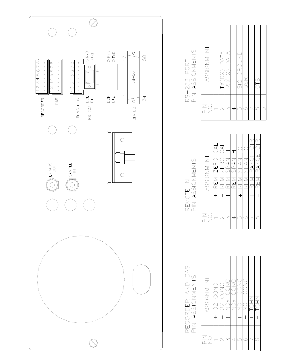
Figure 2-3: Rear Panel with O2 Option
Teledyne API Model 200AH NOX Analyzer Instruction Manual, 06492, Rev. G2
2-6
Figure 2-4: Inlet and Exhaust Venting Recommendations

Teledyne API Model 200AH NOX Analyzer Instruction Manual, 06492, Rev. G2
2-7
2.3. Initial Operation
1. Turn on the instrument power.
2. The display should immediately light, showing the computer’s memory configuration, then
the instrument type - M200AH. If you are unfamiliar with the M200AH, we recommend that
you read the overview Section 4 before proceeding. A diagram of the software menu trees is
in Figure 5-1 and Figure 5-2.
3. The M200AH requires about 30 minutes for all internal components to come to temperature.
During this time the ozone generator power is OFF until the membrane dryer has time to
purge itself, therefore there will be no response from the instrument, even if span gas is
coming in the sample port. Many warning conditions are not displayed during this time, even
though temperatures and other conditions are out of specification. All warning messages are
enabled after 30 minutes of operation.
4. While waiting for instrument temperatures to stabilize, you can check for correct operation
by using some of the M200AH's diagnostic and test features.
5. Examine the TEST functions by comparing the values listed in Table 2-1 to those in the
display. Remember that as the instrument warms up the values may not have reached their
final values yet. If you would like to know more about the meaning and utility of each TEST
function refer to Table 9-1. Also, now is a good time to verify that the instrument was
shipped with the options you ordered. Table 2-1 also contains the list of options. Section 6
covers setting up the options.
6. Electric Test and Optic Test both generate simulated signals in the M200AH.
A. Electric Test checks the electronics of the PMT signal path. To operate Electric Test from
the front panel:
1) Scroll the TEST function to PMT.
2) Press SETUP-MORE-DIAG, then press ENTR to accept the default password. Scroll
to Electric Test and press ENTR to turn it on. Instrument responses should come to the
values indicated in Table 2-1. To turn off this test press EXIT. For more information
on the circuitry being tested refer to the Troubleshooting Section 9.1.3.2.
B. Optic Test is an "end to end" test of the analyzer HVPS-PMT-detector-electronics-
computer. It simulates a signal by turning on a LED in the Sensor Module. To operate
Optic Test from the front panel:
1) Scroll the TEST function to PMT.
2) Press SETUP-MORE-DIAG, then press ENTR to accept the default password. Scroll
to Optic Test and press ENTR to turn on optic test. Instrument response should come
up to the values indicated in Table 2-1. To turn off this test press EXIT. To return to
the SAMPLE mode press EXIT until SAMPLE is displayed in the upper left display.
For more information about OT operation see Section 9.1.3.3.

Teledyne API Model 200AH NOX Analyzer Instruction Manual, 06492, Rev. G2
2-8
7. When the instrument is warmed up, re-check the TEST functions against Table 2-1. All of
the readings should compare closely with those in the table. If they do not see Section 9.1.1.
The next task is to calibrate the analyzer. There are several ways to do a calibration, they are
summarized in Table 7-1. For a preliminary checkout we recommend calibration with span
gas coming in through the sample port. The procedure is:
Step 1 - Set the range, then enter the expected NOx, NO and O2 span gas concentrations:
Step For Units w/o
O2 Option For Units with
O2 Option Comment
1. Press
CAL-CONC-NOX Press
CAL-NOX-ENTR
CONC-NOX
This key sequence causes the M200AH to
prompt for the expected span concentration.
Enter the span value by pressing the key under
each digit until the expected value is set.
2. Press ENTR Press ENTR ENTR stores the expected NOx span value. The
internal formulas are adjusted to compute this
number when span gas concentration is input
into the instrument.
3. Press
CAL-CONC-NO Press
CAL-NOX-ENTR
CONC-NO
In the same CAL-CONC sub menu press the
NO button and enter the expected NO span
value. As before this value will be used in the
internal formulas to compute the NO
concentration value.
4. Press ENTR Press ENTR ENTR stores the expected NO span value. The
internal formulas are adjusted to compute this
number when span gas concentration is input
into the instrument.
5. Press
CAL-O2-CONC Enter the expected O2 span value by pressing
the key under each digit until the expected
value is set.
6. Press ENTR ENTR stores the expected O2 span value. The
internal formulas are adjusted to compute this
number when span gas concentration is input
into the instrument.
7. Press EXIT Press EXIT Returns instrument to SAMPLE mode.
8. Press
SETUP-RNGE-
MODE-SNGL
Press
SETUP-RNGE-
MODE-SNGL
If necessary, you may want to change ranges.
Normally the instrument is shipped in single
range mode set at 100 ppm for NOx and 25%
for O2. We recommend doing the initial
checkout with these ranges.
9. Press
SETUP-RNGE-SET Press
SETUP-RNGE-SET
After SETUP-RNGE-SET, enter 100 and press
ENTR. The instrument will now be in the
100 ppm range for NOx and (if installed) will
display the O2 range. Enter 25.0 and press
ENTR.

Teledyne API Model 200AH NOX Analyzer Instruction Manual, 06492, Rev. G2
2-9
Step 2 - Calibrate the instrument for NOX:
Zero/Span Calibration Procedure
Step For Units w/o
O2 Option For Units with
O2 Option Comment
1. Input NOX Zero gas Input NOX Zero gas Allow Zero gas to enter the sample port on
the rear of the instrument.
2. Press CAL Press CAL-NOX The M200AH enters the calibrate mode from
sample mode.
3. Wait 10 min Wait 10 min Wait for reading to stabilize at the zero value.
If you wait less than 10 minutes the final zero
value may drift.
4. Press ZERO Press ZERO The ZERO button will be displayed.
5. Press ENTR Press ENTR Pressing ENTR actually changes the
equations and zeros the instrument.
6. Press EXIT and
input NOX Span gas Press EXIT and
input NOX Span gas M200AH returns to the CAL menu. Now
switch gas streams to span gas.
7. Wait 10 min Wait 10 min Wait for reading to stabilize at the span
value.
8. Press SPAN Press SPAN The SPAN button should be displayed. If
there is no SPAN button check the
Troubleshooting Section 9.2.8 for
instructions on how to proceed. In certain
circumstances at low span gas concentrations
both the ZERO and SPAN buttons will
appear.
9. Press ENTR Press ENTR Pressing ENTR actually changes the
equations so that the concentration displayed
is the same as the expected span
concentration you entered above, thus
spanning the instrument.
10. Press EXIT Press EXIT Pressing EXIT returns the instrument to
SAMPLE mode.
11. Input O2 Zero gas Allow Zero gas to enter the sample port on
the rear of the instrument.
12. Press CAL-O2 The M200AH enters the calibrate mode from
sample mode.
(table continued)

Teledyne API Model 200AH NOX Analyzer Instruction Manual, 06492, Rev. G2
2-10
Zero/Span Calibration Procedure (Continued)
Step For Units w/o
O2 Option For Units with
O2 Option Comment
13. Wait 10 min Wait for reading to stabilize at the zero value.
If you wait less than 10 minutes the final zero
value may drift.
14. Press ZERO The ZERO button will be displayed.
15. Press ENTR Pressing ENTR actually changes the
equations and zeros the O2 channel of the
instrument.
16. Press EXIT and
input O2 Span gas M200AH returns to the CAL menu. Now
switch gas streams to span gas.
17. Wait 10 min Wait for reading to stabilize at the span
value.
18. Press SPAN The SPAN button should be displayed. If
there is no SPAN button check the
Troubleshooting Section 9.2.8 for
instructions on how to proceed. In certain
circumstances at low span gas concentrations
both the ZERO and SPAN buttons will
appear.
19. Press ENTR Pressing ENTR actually changes the
equations so that the concentration displayed
is the same as the expected span
concentration you entered above, thus
spanning the instrument.
20. Press EXIT Pressing EXIT returns the instrument to
SAMPLE mode.

Teledyne API Model 200AH NOX Analyzer Instruction Manual, 06492, Rev. G2
2-11
Step 3 - Review Quality of calibration:
Calibration Quality Check Procedure
Step For Units w/o
O2 Option For Units with
O2 Option Comment
1. Scroll the TEST
function menu until
the NOX SLOPE is
displayed.
Scroll the TEST
function menu until
the NOX SLOPE is
displayed.
The SLOPE value for NOX should be 1.0
0.3. If the value is not in this range, check
Section 7.1 or 9. If the SLOPE value is in the
acceptable range the instrument will perform
optimally.
2. Scroll the TEST
function menu until
the NO SLOPE is
displayed.
Scroll the TEST
function menu until
the NO SLOPE is
displayed.
The SLOPE value for NO should be 1.0
0.3. If the value is not in this range, check
Section 7.1 or 9. If the SLOPE is in the
acceptable range the instrument will perform
optimally.
NOTE: The NO and NOx slopes should be
equal within 0.3.
3. Scroll the TEST
function menu until
the O2 SLOPE is
displayed.
The SLOPE value for O2 should be 1.0 0.3.
If the value is not in this range, check Section
7.1 or 9. If the SLOPE value is in the
acceptable range the instrument will perform
optimally.
4. Scroll the TEST
function menu until
the NOX OFFS is
displayed.
Scroll the TEST
function menu until
the NOX OFFS is
displayed.
The M200AH will display the OFFSET
parameter for the NOX equation. This number
should be near zero. A value of 0.0 50
indicates calibration in the optimal range. If
the OFFSET value is outside this range,
check Section 7.1 or 9.1 for procedures to
correct the OFFSET value to near zero.
5. Scroll the TEST
function menu until
the NO OFFS is
displayed.
Scroll the TEST
function menu until
the NO OFFS is
displayed.
The Instrument will now display the NO
OFFSET value. It should also have a value
near zero (0.0 50).
6. Scroll the TEST
function menu until
the O2 OFFS is
displayed.
The Instrument will now display the O2
OFFSET value. It should also have a value
near zero (0.0 50).
Step 4 - The M200AH is now ready to measure sample gas.
Teledyne API Model 200AH NOX Analyzer Instruction Manual, 06492, Rev. G2
2-12
Figure 2-5: Front Panel
Teledyne API Model 200AH NOX Analyzer Instruction Manual, 06492, Rev. G2
2-13
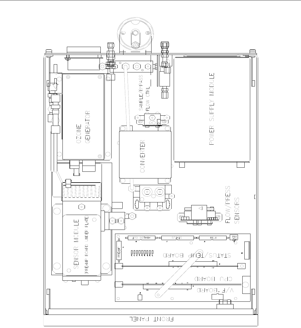
Figure 2-6: Assembly Layout
Teledyne API Model 200AH NOX Analyzer Instruction Manual, 06492, Rev. G2
2-14
Figure 2-7: Assembly Layout – O2 Sensor Option

Teledyne API Model 200AH NOX Analyzer Instruction Manual, 06492, Rev. G2
2-15
Table 2-1: Final Test and Calibration Values
TEST Values Observed
Value Units Nominal Range Reference Section
RANGE ppm 5-5000 5.3.4
O2 RANGE % 5-100 5.3.4
NOX STB ppm 0.0 - 0.2 9.1.1, 9.2.5, Table 9-1
SAMP FLW cc/min 300 50 (Default)
550 50 (Optional)
9.3.7, Table 9-1
OZONE FL cc/min 250 15 9.3.6
PMT mV 0-5000 9.3.8
AZERO mV -10 to +50 4.1
HVPS V 400 - 700 constant 9.3.8.5
DCPS mV
2500 200 9.3.5
RCELL TEMP C 50 2 9.3.8.2
O2 CELL TEMP(1) C 50 2
BLOCK TEMP(2) C 50 2 9.3.4.1
BOX TEMP C 8-48 9.3.4.1
PMT TEMP C 7 1 9.3.8.4
CONV TEMP C 700 10 (Std)
315 5 (Moly)
9.3.4.1
RCEL PRES IN-Hg-A 2 - 10 constant 9.3.7
SAMP PRES IN-Hg-A 25 - 30 constant 9.3.7
Electric Test &Optic Test
Electric Test
PMT Volts mV 2000 200 9.1.3.2
NO Conc ppm 250 25 9.1.3.2
NOx Conc ppm 250 25 9.1.3.2
OPTIC TEST
PMT Volts mV 100 20 9.1.3.3
NO Conc ppm 12.5 2 9.1.3.3
NOx Conc ppm 12.5 2 9.1.3.3
(table continued)
Teledyne API Model 200AH NOX Analyzer Instruction Manual, 06492, Rev. G2
2-16
Table 2-1: Final Test and Calibration Values (Continued)
Parameter Observed
Value Units Nominal Range Reference Section
NO Span Conc ppm 0.5 - 5000 Table 7-3
NOx Span Conc ppm 0.5 - 5000 Table 7-3
O2 Span Conc % 5 - 100 Table 7-3
NO Slope - 1.0 0.3 7.1, 7.10
NOx Slope - 1.0 0.3 7.1
O2 Slope - 1.0 0.3 7.1, 7.10
NO Offset mV 25 7.1, 7.2
NOx Offset mV 25 7.1, 7.2
O2 Offset % 1.0 7.1, 7.2
Conv Efficiency % 0.75 - 1.10 7.11, 5.2.2.7
NOx Noise at Zero ppm 0.0 - 0.2 Table 9-1
NOx Noise At Span ppm 0.1 - 0.5 Table 9-1
O2 Noise at Zero % Table 9-1
O2 Noise At Span % Table 9-1
Measured Flows
Sample Flow cc/min 50 20 9.3.7, Figure 9-8
Bypass Flow cc/min 250 (Std)
500 (Optional) Figure 8-4
Ozone Flow cc/min 250 15 9.3.7, Figure 9-8
Factory Installed Options Option Installed
Power Voltage/Frequency
O2 Sensor
Rack Mount, w/ Slides
Rack Mount, w/ Ears Only
Rack Mount, External Pump w/o Slides
Stainless Zero/Span Valves
4-20 mA Current Loop Output, Isolated
Bypass flow 500 cc/min
Molybdenum Converter
Desiccant Canister - O3 generator
PROM # Serial #
Date Technician
(1) Units with O2 Option , Only
(2) Units w/o O2 Option, Only

Teledyne API Model 200AH NOX Analyzer Instruction Manual, 06492, Rev. G2
3-1
3. SPECIFICATIONS, WARRANTY
3.1. Specifications
NOX Specifications O2 Option
Operating Modes NO/NOx switching mode, NO only
mode, NOx only mode. Paramagnetic Sensor
Ranges In 1 ppm increments from 5 ppm to
5000 ppm; Single range, independent
ranges or autoranging
In 1 % increments from 5 % to
100%, Independent of NOX range
Noise at zero <0.020 ppm RMS 0.05% O2
Noise at span <0.5% of reading RMS above 20 ppm <0.1% O2
Detection Limit (Note 1) 0.040 ppm 0.1% O2
Zero Drift (Note 2) <0.5% full scale/24 hours 0.1% O2
Zero Drift (Note 2) <1.0% full scale/7 days 0.1% O2
Span Drift (Note 2) <1% FS/24 hours 0.1% O2
Lag Time
- Switching Mode - 20 sec (Note 3)
- NOx mode - 4 sec (Note 3)
< 4sec
Response Time
- Switching Mode - 95% in < 40 sec (Note 3)
- NOx mode - 95% in < 10 sec (Note 3)
95% in <10 sec
Sample Flow Rate (Analyzer) 370 cc/min 10% (Including bypass)
Sample Flow Rate (Sensors) 40 cc/min 10% 80 cc/min 10%
Linearity 1% of full scale 0.1% O2
Precision 0.5% of reading 0.1% O2
Temperature Range 5-40C
Humidity 0-95% RH non-condensing
Temp Coefficient < 0.1% per C < 0.1% per C
Voltage Coefficient < 0.1% per V < 0.1% per V
Dimensions HxWxD 7"x17"x23.6" (18 cm x 43 cm x 61 cm)
Weight, Analyzer 45 lbs (22 kg)
Weight, Pump Pack 16 lbs (7 kg)
Power, Analyzer 100 V~ 50/60 Hz, 120 V~ 60 Hz, 220 V~ 50 Hz, 240 V~ 50 Hz, 200 watts
Power, Analyzer4 230 V~ 50 Hz, 2.5A
Power, Ext Pump 110 V~ 60 Hz, 220 V~ 50 Hz, 240 V~ 50 Hz, 295 watts
Power, Ext Pump4 230 V~ 50 Hz, 2.5A
Environmental Installation Category (Over-voltage Category) II
Pollution Degree 2
Analog Resolution 1 part in 2048 of selected voltage or
current range 1 part in 2048 of selected voltage or
current range
Recorder Output 0-100mV, 0-1, 5, 10v, bipolar 0-100mV, 0-1, 5, 10v, bipolar
Current Loop Option 4-20ma isolated 4-20ma isolated
Status 12 Status Outputs from opto-isolator
Measurement Units ppm, mg/m3 %
1. Defined as twice the zero noise level.
2. At constant temperature and voltage.
3. Lag & response times longer for external converter option.
4. Electrical ratings for CE Mark compliance.

Teledyne API Model 200AH NOX Analyzer Instruction Manual, 06492, Rev. G2
3-2
3.2. Warranty
WARRANTY POLICY (02024c)
Prior to shipment, Teledyne API equipment is thoroughly inspected and tested. Should
equipment failure occur, Teledyne API assures its customers that prompt service and support
will be available.
COVERAGE
After the warranty period and throughout the equipment lifetime, Teledyne API stands ready to
provide on-site or in-plant service at reasonable rates similar to those of other manufacturers in
the industry. All maintenance and the first level of field troubleshooting is to be performed by
the customer.
NON-TELEDYNE API MANUFACTURED EQUIPMENT
Equipment provided but not manufactured by Teledyne API is warranted and will be repaired to
the extent and according to the current terms and conditions of the respective equipment
manufacturers warranty.
GENERAL
Teledyne API warrants each Product manufactured by Teledyne API to be free from defects in
material and workmanship under normal use and service for a period of one year from the date of
delivery. All replacement parts and repairs are warranted for 90 days after the purchase.
If a Product fails to conform to its specifications within the warranty period, Teledyne API shall
correct such defect by, in Teledyne API's discretion, repairing or replacing such defective
Product or refunding the purchase price of such Product.
The warranties set forth in this section shall be of no force or effect with respect to any Product:
(i) that has been altered or subjected to misuse, negligence or accident, or (ii) that has been used
in any manner other than in accordance with the instruction provided by Teledyne API or (iii)
not properly maintained.
THE WARRANTIES SET FORTH IN THIS SECTION AND THE REMEDIES
THEREFORE ARE EXCLUSIVE AND IN LIEU OF ANY IMPLIED WARRANTIES OF
MERCHANTABILITY, FITNESS FOR PARTICULAR PURPOSE OR OTHER
WARRANTY OF QUALITY, WHETHER EXPRESSED OR IMPLIED. THE
REMEDIES SET FORTH IN THIS SECTION ARE THE EXCLUSIVE REMEDIES FOR
BREACH OF ANY WARRANTY CONTAINED HEREIN. TELEDYNE API SHALL
NOT BE LIABLE FOR ANY INCIDENTAL OR CONSEQUENTIAL DAMAGES
ARISING OUT OF OR RELATED TO THIS AGREEMENT OF TELEDYNE API'S
PERFORMANCE HEREUNDER, WHETHER FOR BREACH OF WARRANTY OR
OTHERWISE.
TERMS AND CONDITIONS
All units or components returned to Teledyne API should be properly packed for handling and
returned freight prepaid to the nearest designated Service Center. After the repair, the equipment
will be returned, freight prepaid.
Teledyne API Model 200AH NOX Analyzer Instruction Manual, 06492, Rev. G2
4-1
4. THE M200AH NOX ANALYZER
4.1. Principle of Operation
4.1.1. NOX Measurement
The Teledyne API Model 200AH Analyzer is designed to measure the concentration of nitric
oxide [NO], total oxides of nitrogen [NOx] and, by calculation, nitrogen dioxide [NO2] (Note: the
calculation of NO2 is not available in instruments equipped with the Oxygen measurement
option.) With the proper setup, it can operate in any of three sampling modes.
Table 4-1: Sampling Modes of the M200AH
Mode Description
NO/NOX
switching mode Converter is switched, measures NO, NOx, and NO2.
NO only mode Converter is switched out of sample stream. Nitric Oxide is only
gas measured.
NOx only mode Converter is switched into the sample stream, NOx is only gas
measured.
Regardless of which sampling mode the instrument is operating in, the signal from the M200AH
comes from the light emitted from the chemiluminescent gas phase reaction of nitric oxide [NO]
and ozone [O3] as follows:
223 O*NOONO
hvNO*NO 22
The reaction of NO with ozone results in electronically excited NO2 molecules as shown in the
first equation above. The excited NO2 molecules release their excess energy by emitting a
photon and dropping to a lower energy level as shown in the second equation. It has been shown
that the light intensity produced is directly proportional to the [NO] concentration present.
In the NO mode, the sample gas is routed directly into the reaction cell. Any NO gas present
reacts with ozone, producing light as described above.
In the NOX mode, the sample gas is routed through a NO2 to NO converter, and any NO2 present
is reduced to NO. The NO initially present remains as NO, therefore the signal is the sum of NO
and NO2 present in the sample gas stream.
In the NO/NOX switching mode the Analyzer samples the gas stream and measures [NO]
concentration by digitizing the signal from the Analyzer's photomultiplier tube (PMT). The
Teledyne API Model 200AH NOX Analyzer Instruction Manual, 06492, Rev. G2
4-2
concentration is measured and stored internally. The valve is then switched, routing the sample
gas through the converter, the signal measured is the NOX concentration which is also stored in
the computer.
The [NO2] component is calculated by subtracting [NOX] - [NO] = [NO2] using the built-in
computer. The three results [NO], [NOX], and [NO2] are then further processed and stored by the
computer yielding several instantaneous and long term averages for all three components.
Periodically, the AutoZero valve switches allowing the analyzer to read zero background. The
AutoZero readings are subtracted from all of the other readings. This improves zero baseline
stability.
4.1.2. Oxygen Measurement (Option)
The Oxygen Sensor used in M200AH utilizes the paramagnetic susceptibility of oxygen, a
physical property that distinguishes oxygen from most other common gases.
The sensor incorporates two nitrogen-filled glass spheres mounted on a strong rare metal taut-
band suspension. This assembly is suspended in a symmetrical non-uniform magnetic field.
When the surrounding gas contains paramagnetic oxygen, the glass spheres are pushed further
away from the strongest part of the magnetic field. The strength of the torque acting on the
suspension is proportional to the oxygen content of the surrounding gases.

Teledyne API Model 200AH NOX Analyzer Instruction Manual, 06492, Rev. G2
4-3
Figure 4-1: Paramagnetic Sensor
Refer to Figure 4-1. The measuring system is “null-balanced”. First, the ‘zero’ position of the
suspension assembly, as measured in nitrogen. is sensed by a split photo-sensor that receives
light reflected from a mirror attached to the suspension assembly. The output from the photo-
sensor is fed back to a coil wound around the suspension assembly. This feedback achieves two
objectives:
a) First, when oxygen is introduced to the cell, the torque acting upon the suspension
assembly is balanced by a restoring torque due to this feedback current in the coil. The
feedback current is directly proportional to the volume magnetic susceptibility of the
sample gas and hence, after calibration, to the partial pressure of oxygen in the sample.
A voltage output is derived which is proportional to the current.
b) Second. the electromagnetic feedback “stiffens” the suspension, damping it heavily and
increasing its natural frequency, making the suspension resilient to shock.
Teledyne API Model 200AH NOX Analyzer Instruction Manual, 06492, Rev. G2
4-4
Figure 4-2: Block Diagram

Teledyne API Model 200AH NOX Analyzer Instruction Manual, 06492, Rev. G2
4-5
4.2. Operation Summary
4.2.1. NOX Sensor Module, Reaction Cell, Detector
The sensor module is where light from the chemilumenescent reaction is generated and detected.
It is the most complicated and critical sub-assembly in the entire analyzer. It consists of the
following assemblies and functions:
1. The reaction cell and ozone flow control module
2. Reaction cell heater/thermistor
3. PMT and High Voltage Power Supply
4. PMT cooler/cold block/heatsink/fan
5. Preamp assembly:
A. Preamp range control hardware
B. HVPS control
C. PMT cooler temp control
D. Electric test electronics
E. Optic test electronics
4.2.2. Oxygen Sensor Module (Option)
The main components of Oxygen Sensor are:
1. The transducer body consists of the paramagnetic cell and the magnet frame.
The interior of the paramagnetic cell is the only sample wetted surface. It is a precision
machined component containing the suspension assembly, and is secured within the magnet
frame.
2. Optical Assembly and Electronics Control PCB.
The optical assembly consists of a precision machined optical mounting bracket onto which
the integrated electronics board and the small photo-sensor board are fitted. The optical
assembly is secured to the magnet frame.
The electronics board contains the LED source, temperature compensation thermistors and
all other associated signal processing components, including a 16-way DC connector and the
multi-turn zero and span potentiometers.

Teledyne API Model 200AH NOX Analyzer Instruction Manual, 06492, Rev. G2
4-6
4.2.3. Pneumatic Sensor Board
The sensor board consists of 2 pressure sensors and a flow sensor. One pressure sensor measures
the pressure in the reaction cell. The reaction cell is maintained at about one-quarter of
atmospheric pressure. The second pressure sensor measures the pressure upstream of the reaction
cell, which is near ambient pressure. From these two pressures the sample flow rate can be
computed and is displayed as sample flow in the TEST menu. Finally, a solid state flow meter
measures the ozone flow directly. Likewise, it is displayed as a TEST function.
The M200AH displays all pressures in inches of mercury-absolute (in-Hg-A). Absolute pressure
is the reading referenced to a vacuum or zero absolute pressure. This method was chosen so that
ambiguities of pressure relative to ambient pressure can be avoided.
For example, if the vacuum reading is 25" Hg relative to room pressure at sea level the absolute
pressure would be 5" Hg. If the same absolute pressure was observed at 5000 ft altitude where
the atmospheric pressure was 5" lower, the relative pressure would drop to 20" Hg, however the
absolute pressure would remain the same 5" Hg-A.
4.2.4. Computer Hardware and Software
The M200AH Analyzer is controlled by a micro computer. The computers' multitasking
operating system allows it to do instrument control, monitor test points, provide analog output
and provide a user interface via the display, keyboard and RS-232 port. These operations appear
to be happening simultaneously but are actually done sequentially based on priority queuing
system maintained by the operating system. The jobs are queued for execution only when
needed, therefore the system is very efficient with computer resources.
The M200AH is a true computer based instrument. The microprocessor does most of the
instrument control functions such as temperature control, valve switching. Data collection and
processing are done entirely in the CPU with the final concentration values being sent to a D/A
converter to produce the instrument analog output.
The computer memory is divided into 3 sections: ROM memory contains the multi-tasking
operating system code plus the instructions that run the instrument. The RAM memory is used to
hold temporary variables and current concentration data. The EEPROM memory contains the
instrument set-up variables such as range and instrument ID number. The EEPROM data is non-
volatile so the instrument can lose power and the current set-up information is preserved.

Teledyne API Model 200AH NOX Analyzer Instruction Manual, 06492, Rev. G2
4-7
4.2.5. V/F Board
The computer CPU board communicates via 2 major hardware assemblies. These are the V/F
board and the front panel display/keyboard. The V/F board communicates with the CPU via the
STD-100 bus.
The V/F board includes of A/D input channels, digital I/O channels, and analog output channels.
The computer receives all of the instrument data and provides all control functions through the
V/F board.
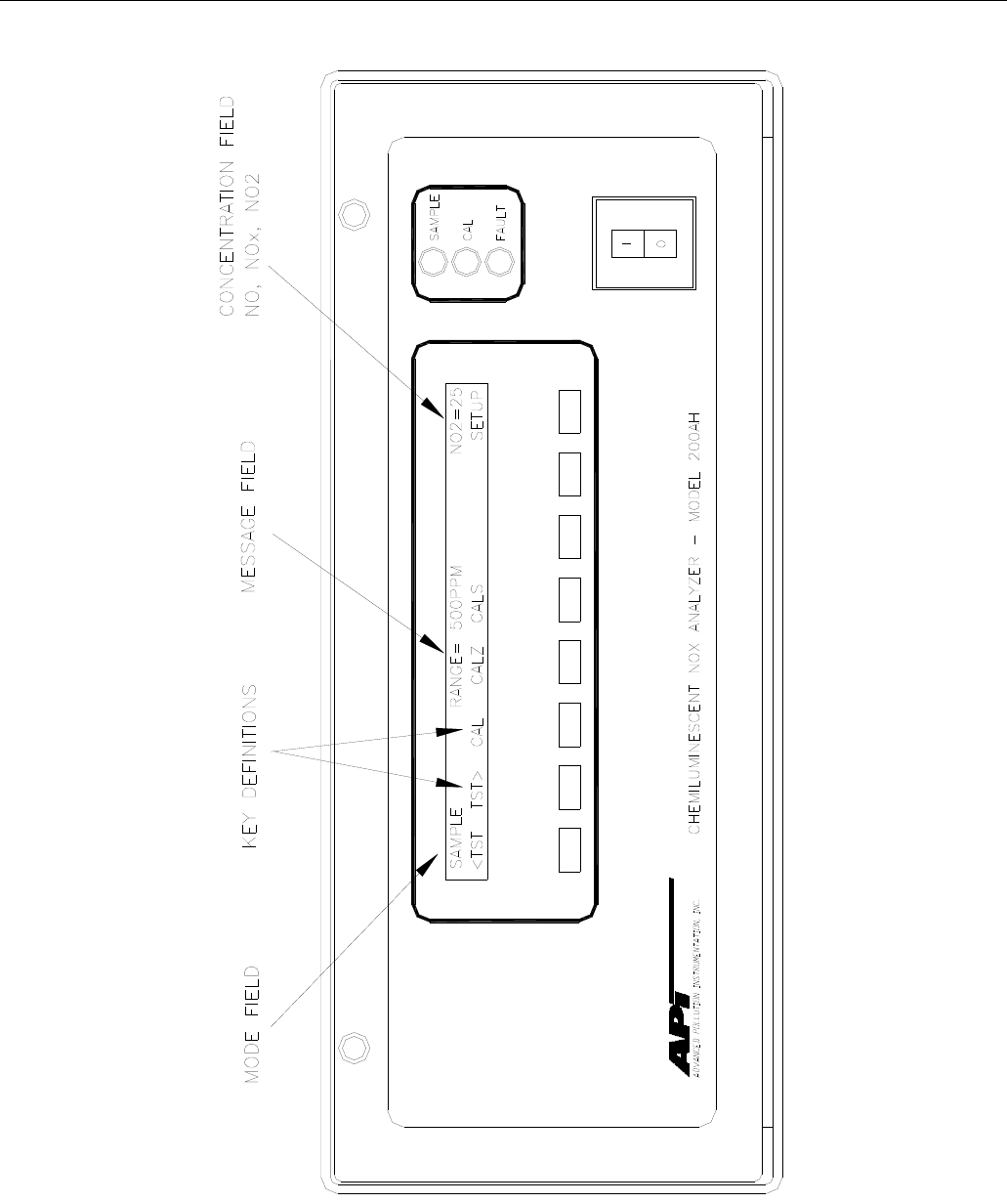
4.2.6. Front Panel
The front panel of the M200AH is shown in Figure 2-5. The front panel consists of a 2 line
display and keyboard, 3 status LED's and power switch. Communication with the display,
keyboard, and status LED's is done via the computers on-board parallel port. The M200AH was
designed as a computer controlled instrument, therefore all major operations can be controlled
from the front panel display and keyboard.
The display consists of 2 lines of 40 characters each. The top line is divided into 3 fields, and
displays information. The first field is the mode field.
The center field displays TEST values. The TEST functions allows you to quickly access many
important internal operating parameters of the M200AH. This provides a quick check on the
internal health of the instrument. The right hand field shows current concentrations values of
NO, NOX, and NO2.
The M200AH can operate in any of 3 different sampling modes - NO only, NOX only, and
NO/NOX switching mode. For the NO or NOX only modes just the single gas being measured is
displayed. For the NO/NOX switching mode, the display scrolls between the NO, NOX, and NO2
concentration values every 4 seconds.
4.2.6.1. Keyboard
The second line of the display contains eight fields, each field defines the key immediately
below it. By redefining the keys dynamically it is possible to simplify the instrument electronics
and user interface.
4.2.6.2. Status LED's
At the right of the display there are 3 status LED's. They can be in three states, OFF, ON, and
Blinking. The meanings of the LED's are given in Table 4-2.

Teledyne API Model 200AH NOX Analyzer Instruction Manual, 06492, Rev. G2
4-8
Table 4-2: Front Panel Status LED's
LED State Meaning
Green Off
On Monitoring
Blinking
NOT monitoring, DAS disabled
Monitoring normally, taking DAS data
Monitoring, DAS in HOLDOFF mode(1)
Yellow Off
On
Blinking
AutoCal disabled
AutoCal enabled
Calibrating
Red Off
Blinking No warnings exist
Warnings exist
(1) This occurs during Calibration, DAS holdoff, after power-up and in Diagnostic mode.
4.2.6.3. Power Switch
The power switch has two functions. The rocker switch controls overall power to the instrument,
in addition it includes a circuit breaker. If attempts to power up the M200AH result in a circuit
breaker trip, the switch automatically returns to the OFF position, and the instrument will not
power up.
4.2.7. Power Supply Module
The Power supply module supplies AC and DC power to the rest of the instrument. It consists of
a 4 output linear DC power supply and a 15 volt switching supply. In addition, it contains the
switching circuitry to drive the DC operated valves and several switched AC loads to operate the
Rx cell heater, converter heaters and the ozone generator. The only voltages not generated in the
PSM are the high voltage DC required by the PMT which is generated inside the sensor module
and the high voltage AC used by the ozone generator.
4.2.8. Pump, Valves, Pneumatic System
A standard M200AH comes with 2 valves, the NO/NOX valve and the AutoZero valve, see
Figure 4-2. Depending on the selected operating mode, the NO/NOX valve:
1. NO only mode - routes sample gas continuously into the reaction cell.
2. NOX only mode - routes sample gas continuously through the converter, then into the
reaction cell.
3. NO/NOX switching mode - switches gas alternately around, then through the converter to
measure NO, NOX, and by calculation NO2.
The AutoZero valve provides a continuous zero reference. Periodically, the valve switches to
turn off sample gas to the reaction cell. The ozone continues to flow. The zero reading is
averaged and used to compensate subsequent readings for PMT zero offset.

Teledyne API Model 200AH NOX Analyzer Instruction Manual, 06492, Rev. G2
4-9
An external pump comes as standard equipment. The Pump Pack includes a vacuum pump and
ozone scrubber. It is supplied with 0.25" tube fitting to connect to the exhaust fitting on the
M200AH rear panel. See Figure 2-4 for hook-up information. The pump pack is turned on by
plugging the power cord into an AC outlet, see Figure 4-3.
The pump is supplied as standard equipment, however if you are supplying a pump, it must have
the following characteristics:
1. The pump must supply 2 slpm at 5"Hg-A.
2. The ozone scrubber must remove all ozone from the analyzer exhaust.
3. Connect the exhaust (Figure 2-4) to a pump with a <3 m length of 1/4" O.D. PTFE tubing.
Failure to meet the performance specifications will result in poor analyzer performance, damage
to the pump, damage to the analyzer, and may jeopardize warranty repairs. Teledyne API
strongly recommends that the factory supplied pump be used with the M200AH.
NOTE
On vacuum vs absolute pressure:
Many vacuum gauges read relative to ambient pressure, therefore
a reading of 25" of mercury (Hg) at sea level (which would give an
absolute pressure of about 5" Hg in the reaction cell) would read
only 20" Hg at high altitude sites. Therefore in this manual the vacuum
specification of 5" Hg pressure is given as an absolute pressure
- 5" Hg-A - reference against zero absolute pressure (a perfect vacuum)
thus removing ambiguities for high altitude sites.
A 47 mm diameter sample filter is provided as standard equipment to remove particulate matter
from the sample gas. It is important that the filter be maintained at regular intervals because
particulates trapped on the filter have been shown to alter the concentration of the sample. A
suggested schedule is shown in Section 8 - Maintenance. It should be noted however that more
or less frequent maintenance may be required depending on the situation.
Teledyne API Model 200AH NOX Analyzer Instruction Manual, 06492, Rev. G2
4-10
Figure 4-3: External Pump Pack
Teledyne API Model 200AH NOX Analyzer Instruction Manual, 06492, Rev. G2
4-11
4.2.9. Ozone Generator
Because of the instability of ozone, it is necessary to generate this gas inside the analyzer. The
ozone generation module consists of a switching power supply that drives a high voltage
transformer and silent discharge tube. The generator’s dry air supply uses a membrane drier to
supply air with a dew point of 0C or less. The exhaust side of the membrane is connected to the
vacuum manifold at the rear of the instrument. A complete description and service requirements
for this module can be found in Section 9.3.6.
Normal room air contains enough water vapor to damage the generator and components
downstream, therefore the ozone GENERATOR MAY NOT TURN ON IMMEDIATELY
AFTER POWER UP. The delay is built into the instrument to allow the dryer to start operating
and purge the system with dry air. Table 4-3 details the conditions for turning on the ozone
generator.
Table 4-3: Ozone Generator Start-up Timing
Time Since Last Power-up Ozone Gen State Program Action
< 1 hour ON at power-up Gen ON immediately after power-up.
> 1 hour OFF at power-up Wait 30 min, then turn gen ON.
4.2.10. NO2 - NO Converter
The converter is a length of 1/8” tubing heated to 700C. The converter's function is to reduce
nitrogen dioxide (NO2) to nitric oxide (NO). The temperature control for this module is done by
the computer. To accurately measure converter efficiency, there should be oxygen present in the
NO2 calibration gas.
NOTE
For the converter to operate properly there should be a few
percent oxygen present in the sample stream.

Teledyne API Model 200AH NOX Analyzer Instruction Manual, 06492, Rev. G2
4-12
THIS PAGE IS INTENTIONALLY LEFT BLANK

Teledyne API Model 200AH NOX Analyzer Instruction Manual, 06492, Rev. G2
5-1
5. SOFTWARE FEATURES
The M200AH control software has two major operating modes. The SAMPLE mode is the
normal mode when the instrument is taking data. The software menu that covers the SAMPLE
mode is diagrammed in Figure 5-1.
When the instrument is initially installed, or problems indicate a need for diagnostics, the
SETUP menu is used. The SETUP menu is diagrammed in Figure 5-2.
5.1. Index to Front Panel Menus
The next several pages contain two different styles of indexes that will allow you to navigate the
M200AH software menus. The first two pages show a "tree" menu structure to let you see at a
glance where each software feature is located in the menu. The second menu contains a brief
description of each key mnemonic and a reference to the section of the manual that describes its
purpose and function in detail.
Teledyne API Model 200AH NOX Analyzer Instruction Manual, 06492, Rev. G2
5-2
Figure 5-1: Sample Menu Tree
Teledyne API Model 200AH NOX Analyzer Instruction Manual, 06492, Rev. G2
5-3
Figure 5-2: Setup Menu Tree
Teledyne API Model 200AH NOX Analyzer Instruction Manual, 06492, Rev. G2
5-4
Figure 5-3: Setup Menu Tree- Units with O2 Sensor
Teledyne API Model 200AH NOX Analyzer Instruction Manual, 06492, Rev. G2
5-5
Figure 5-4: Setup Menu Tree – Units with O2 Sensor

Teledyne API Model 200AH NOX Analyzer Instruction Manual, 06492, Rev. G2
5-6
5.1.1. Sample Menu
Table 5-1: M200AH Sample Menu Structure
Level 1 Level 2 Level 3 Level 4 Level 5 Description Reference
Section
TEST
TST> Test functions 5.2.1,
Table 9-1
CAL Zero/Span calibration w/ gas through sample
port 5.2.2.1, 7.1
CALZ Zero calibration w/ zero gas from zero valve
option 5.2.2.3,
7.1, 7.2
CALS Span calibration w/ span gas from low or high
concentration span valve option 5.2.2.4,
7.1, 7.2
LOW/
HIGH Only present if AutoRange is selected. Used
to select which range instrument will be
calibrated in. Selects which slopes, offsets,
expected span values, etc. will be updated and
displayed.
5.3.4.2, 7.8
ZERO Press ZERO then ENTR will zero analyzer 5.2.2.3,
7.1, 7.2
SPAN Press SPAN then ENTR will span analyzer 5.2.2.5,
7.1, 7.2,
5.2, 2.3
CONC Expected NO/NOx span concentrations and
Conv efficiency setup Table 7-3
NOX
CONC Enter expected NOx span concentration 5.2.2
Table 7-3
NO
CONC Enter expected NO span concentration 5.2.2,
Table 7-3
CONV Sub-menu for converter efficiency setup and
verification 5.2.2.7,
7.11
NO2 Expected NO2 concentration for converter
efficiency calculation 5.2.2.7,
7.11
CAL Automatic converter efficiency calibration
and entry 5.2.2.7,
7.11
SET Set the converter efficiency manually 5.2.2.7,
7.11
SETUP The SETUP Menu - See next table. Table 5-2

Teledyne API Model 200AH NOX Analyzer Instruction Manual, 06492, Rev. G2
5-7
5.1.2. Set-Up Menu
Table 5-2: M200AH Setup Menu
Level 1 Level 2 Level 3 Level 4 Description Reference
Section
CFG CFG is primarily used for showing
special configuration options and
factory special software.
5.3.1
PREV,
NEXT,
LIST
PREV, NEXT can be used to scroll
through the configuration list. LIST
automatically scrolls the list.
5.3.1
AUTOCAL Automatic span check or calibration 5.3.2
PREV
SEQUENCE Select a sequence of pre programmed
calibration commands
Scroll backwards
5.3.2
NEXT
SEQUENCE Select a sequence of pre programmed
calibration commands
Scroll forwards
5.3.2
MODE Choose from a list of 7 modes plus
disable 5.3.2
PREV Scroll back to choose type of
calibration performed 5.3.2
NEXT Scroll forward to choose type of
calibration performed 7.7
DISABLE Disable selected calibration sequence. 7.7
ZERO Do a zero calibrate 7.7
ZERO-LO Do a zero and low span calibrate 5.3.2, 6.2
ZERO-HI Do a zero and high span calibrate 5.3.2, 6.2
(table continued)
Teledyne API Model 200AH NOX Analyzer Instruction Manual, 06492, Rev. G2
5-8
Table 5-2: M200AH Setup Menu (Continued)
Level 1 Level 2 Level 3 Level 4 Description Reference
Section
ZERO-LO-
HI Do a zero, low, and high span
calibrate 5.3.2, 6.2
LO Do a low span calibrate 5.3.2, 6.2
HI Do a high span calibrate 5.3.2, 6.2
LO-HI Do a low and high span calibrate 5.3.2, 6.2
SETTINGS
TIMER
ENABLE Enable/Disable chosen sequence 5.3.2,6.2
START
DATE Start date of selected sequence 5.3.2, 6.2
START
TIME Start time of selected sequence 5.3.2, 6.2
DELTA
DAYS Number of days to shift start time
each time sequence is run 5.3.2, 6.2
DELTATI
ME Number of hours to shift start time
each time sequence is run 5.3.2, 6.2
DURATIO
N Number of minutes to spend at each
step in sequence 5.3.2, 6.2
CALIBRA
TE ON=compute new slope and/or offset
OFF=do a span/zero check 5.3.2, 6.2
RANGE
TO CAL If AutoRange is ON, select which
range to calibrate LO or HI 5.3.2, 6.2

Teledyne API Model 200AH NOX Analyzer Instruction Manual, 06492, Rev. G2
5-9
Table 5-3: M200AH Setup Menu
Level 1 Level 2 Level 3 Level 4 Level 5 Description Reference
Section
DAS Data Acquisition menu 5.3.3
VIEW Select which DAS data collector to view 5.3.3
PREV-
NEXT Scroll through data collectors CONC,
PNUMTC, CAL DAT
EDIT UP Examine the DAS data buffer
UP10 Move UP 10 averages in the DAS data
buffer
DOWN Examine the DAS data buffer - move
down and display next average
DOWN10 Move DOWN 10 averages in the DAS
data buffer
RANGE Sets the output range 5.3.4
MODE Type of range output 5.3.4
SING All 3 outputs are on the same single
range 5.3.4.1
AUTO All 3 outputs AutoRange between 2
different ranges 5.3.4.2
REM Same as AutoRange, except external
contacts set range 5.3.4.2
IND Each range can be set independently 5.3.4.3
OFFS Allows a offset bias voltage to all
analog output channels 5.3.6
UNIT Unit selection menu 5.3.4.6
PPM Selects PPM units 5.3.4.6
MGM Selects milligrams per cubic meter units 5.3.4.6
SET
IF
SINGLE SET Sets the range of the instrument if in
SINGLE range mode 5.3.4.1
IF
AUTO
OR
REM
LO/HI Sets the low and high ranges for
AUTORANGE or Remote Range. 5.3.4.2
IF
INDEP NO NOX
NO2 Sets each INDEPENDENT range.
DIL Sets dilution factor. 5.3.4.5

Teledyne API Model 200AH NOX Analyzer Instruction Manual, 06492, Rev. G2
5-10
Table 5-4: M200AH Setup Menu
Level 1 Level 2 Level 3 Level 4 Level 5 Description Reference
Section
PASS Password protection 5.3.5
ON/OFF Enable password protection of
calibration and setup menus. 5.3.5
CLOCK Time of day clock 5.3.6
TIME Set the time of day 5.3.6
DATE Set the date 5.3.6
MORE Drop to next lower level of menus
COMM Communications setup menu 5.3.8
BAUD Set the BAUD rate, there are more RS-
232 options in the VARS menu. 5.3.8
ID Set the instrument ID 5.3.8
VARS Internal software variables 5.3.9
PREV,
NEXT,
JUMP,
EDIT
PREV, NEXT scroll up and down
through the VARS menu. Jump will go
to variable number selected, EDIT will
allow changing the selected variable.
5.3.9
VARS User level variables. 5.3.9
DIAG Diagnostic menu 5.3.7, 9
PREV,
NEXT,
JUMP
PREV, NEXT scroll up and down
through the DIAG menu. 5.3.7, 9
8 DIAG
MODES There are 8 diagnostic menus for testing
various sections of the M200AH 9.1.3
EXIT Exit from the SETUP menu 9.1

Teledyne API Model 200AH NOX Analyzer Instruction Manual, 06492, Rev. G2
5-11
5.2. Sample Mode
5.2.1. Test Functions
NOTE
In any of the following TEST functions, if a value of
XXXX is displayed, that indicates an off scale and
therefore meaningless reading.
TEST functions allow the operator to examine several important operating parameters of the
M200AH to verify correct Analyzer operation. If faults are discovered, refer to Troubleshooting
Section 9.
Range (RANGE)
This is the Range of the instrument. In single range mode there is one range for all 3 rear panel
analog outputs.
The AutoRange option allows 2 different ranges for each channel, and will automatically switch
to the other range dynamically as concentration values require. By selecting Remote AutoRange,
the range change can be controlled remotely. The TEST values will show the range the
instrument is currently operating in, and will dynamically display range change information
when necessary.
Independent range option allows different ranges for each output. When enabled, there will be
three range values displayed, NO, NOX and NO2.
NOTE
Each of the range modes Single range, Auto range, and
Independent ranges are mutually exclusive.
Oxygen Sensor Range (O2 RANGE) (Option)
For units equipped with the O2 Sensor Option, this is the Full Scale Range of the rear panel O2
analog output.

Teledyne API Model 200AH NOX Analyzer Instruction Manual, 06492, Rev. G2
5-12
Signal Stability (STABIL, NOX STB)
The instrument noise is computed by calculating the standard deviation of the last 10 minutes of
concentration data. If NO/ NOX switching mode is selected, the noise reading is that of the NOX
channel. If NO only or NOX only mode is selected the Noise applies to the mode selected. The
noise value only becomes meaningful if sampling a constant concentration for more than
10 minutes. The noise value should be compared to the value observed in the factory check-out.
Sample Flow (SAMP FLW)
The SAMPLE FLOW test function is computed from the pressure measured up-stream of the
sample flow orifice. The pressure down-stream of the orifice is also checked to assure the
assumptions of the equation are valid. This will register variations in flow caused by changes in
atmospheric pressure, but will not detect a plugged sample flow orifice. The sample flow into the
reaction cell is 50 10 cc/min with a bypass flow of 250 cc/min 50. The instrument reports a
flow of 290 50 cc/min.
Ozone Flow (OZONE FLW)
The OZONE FLOW test function is directly measured by a solid state flow meter. Variations in
this value indicate variations in ozone flow. The nominal value for ozone flow is 250
10 cc/min.
PMT Voltage (PMT)
The PMT VOLTAGE measures the PMT signal at the output of the preamp board. The
waveform of the PMT voltage can be complex, and vary from near 0 mV when zero gas is in the
reaction cell to 5000 mV when there is large amounts of NO being measured. If the PMT reading
is consistently 5000 mV, that indicates an off-scale reading. Typical readings bounce around,
which is normal.
AutoZero Voltage (AZERO)
The AutoZero Voltage is the PMT output when the AutoZero valve is actuated. It provides a
zero reference which is subtracted from all NO and NOX readings. The value typically will be
near
0 mV. Readings in the range –10 to +50 mV are acceptable. High readings indicate a light leak
in the reaction cell, recent exposure of the PMT to light, or contamination in the reaction cell.
High Voltage Power Supply Voltage (HVPS)
The HVPS reading is a measure of the scaled-up HVPS programming voltage. The voltage used
to set the HVPS output is generated on the Preamp board. Its value is between 0 and 1 volt,
corresponding to a voltage of 0 to 1000 volts out of the HVPS. The HVPS front panel TEST
measurement should typically be in the range of 400-600V.

Teledyne API Model 200AH NOX Analyzer Instruction Manual, 06492, Rev. G2
5-13
DC Power Supply Voltage (DCPS)
The DCPS voltage is a composite of the 5 and 15 VDC voltages in the Power Supply Module.
This is meant to be a quick indicator to show if the PSM is working correctly. The nominal value
is 2500 mV 200 mV.
Reaction Cell Temperature (RCEL TEMP)
This is a measurement of the temperature of the reaction cell. It is controlled by the computer to
50 2C. Temperatures outside this range will cause the M200AH output to drift.
Box Temperature (BOX TEMP)
This TEST function measures the temperature inside the chassis of the M200AH. The
temperature sensor is located on the Status/Temp Board. Typically it runs 2 to 10C higher than
the ambient temperature. The M200AH has been engineered to maintain stable output over 5 to
40C ambient temperature range.
PMT Temperature (PMT TEMP)
The temperature of the PMT is closely controlled by a dedicated proportional temperature
controller. The nominal set-point is 7 1C. Readings outside this range will cause instrument
drift due to gain changes in the PMT detector.
Block Temperature (BLOCK TEMP)
The block temperature is the temperature of the sample flow orifice. The block is mounted near
the rear of the instrument and is located upstream of the converter. Running the converter at low
pressure improves its conversion efficiency. The normal temperature of the sample orifice block
is 50 2C, and is controlled by the computer.
Oxygen Sensor Temperature (O2 TEMP) (Option)
For instruments equipped with O2 sensor option, the O2 temperature reading replaces the Block
Temp reading and is the temperature of the oven housing the O2 sensor. Also included the oven
is the sample flow control orifice. The normal temperature of the oven is 50 2°C, and is
controlled by the computer.
Converter Temperature (CONV TEMP)
The converter temperature monitors the temperature of the NO2-to-NO converter and is
controlled by the computer. The nominal set-point is 700 10°C. The temperature sensor inside
the converter is a type-K thermocouple. The thermocouple amplifier is located on the
STATUS/TEMP board. If the thermocouple breaks, the circuit will turn off power to the heater.

Teledyne API Model 200AH NOX Analyzer Instruction Manual, 06492, Rev. G2
5-14
If the analyzer is equipped with the molybdenum converter option the TEST function will report
MOLY TEMP, the temperature setpoint will be 315 10°C.
If the analyzer is equipped with the Model 501 external converter option, the converter
temperature is shown on the front panel of the M501. The TEST function O3KL will report the
temperature of the catalytic ozone killer located inside the converter can.
Reaction Cell Pressure (RCEL)
The pressure in the reaction cell is measured by a solid state pressure sensor which measures
absolute pressure. Absolute pressure was chosen because it is an unambiguous measure of cell
pressure. This pressure will vary depending on several things.
1. The type of pump attached to the analyzer.
2. Variations in local weather will cause a 0.3 in-Hg change in pressure.
3. The altitude of the analyzer will cause the cell pressure to change.
Nominal values are 3 to 10 in-Hg-A. Typical reading is about 5 in-Hg-A at sea level for the
standard pump.
Sample Pressure (SAMP)
The sample pressure is measured by one of the pressure sensors on the sensor board. The sample
pressure typically runs slightly below atmospheric pressure. Sample pressure will change with
varying atmospheric pressure (like the weather) because the sensor is an absolute pressure
sensor. It will also change with altitude.
NOX, NO, O2 Slope and Offset Values (NOX SLOPE, NOX OFFS, NO SLOPE, NO OFFS,
O2 SLOPE, O2 OFFS)
The slope (m) and intercept (b) coefficients of straight line equations (y = mx + b) determine the
calibration of the M200AH. The slope parameter(m) can be thought of as a gain term which
determines the steepness of the calibration curve. The offset (b) parameter compensates for
differences in the background signal of the NO and NOX channels. This is primarily due to the
background of the converter.
These parameters contain valuable information about the quality and validity of the calibration.
For example the NO and NOX slope values should not differ by more than 0.1 from each other.
Larger values indicate a flow imbalance such as a leak or problems with the converter. Refer to
Section 7.10 Calibration Quality for details on how to use these values.
Time (TIME)
This is the output of the internal time of day clock.

Teledyne API Model 200AH NOX Analyzer Instruction Manual, 06492, Rev. G2
5-15
5.2.2. CAL, CALS, CALZ, Calibration Functions
The calibration and zero/span checking of the M200AH analyzer is treated in detail in Section 7,
Table 7-1 summarizes types of calibration.
5.2.2.1. CAL, CALS, CALZ
The CAL, CALS, and CALZ keys control the calibration functions of the analyzer. In the CAL
mode the analyzer can be calibrated with zero/span gas coming in through the sample input port
on the rear panel. If the analyzer is equipped with the Zero/Span valve option, the CALZ and
CALS buttons operate the Zero/Span valves. The setup of this option is covered in Section 6.2,
and operation is explained in Section 7.
5.2.2.2. Gas To Cal
For units equipped with the Oxygen Sensor Option, depressing the CAL key will cause the
instrument to prompt for which gas sensor to calibrate; NOX or O2. After the desired gas is
selected, the instrument will display ZERO, SPAN, and CONC keys as described below.
5.2.2.3. Zero
Pressing the ZERO key along with ENTR will cause the instrument to adjust the OFFSET value
of the internal formulas so that the instrument reads zero. The M200AH allows zero adjustment
over a limited range of signal levels, therefore the signal does not have to be exactly zero for the
instrument to do a zero cal. The instrument will not, however, allow a zero cal on any signal
level, therefore it is not possible to zero the instrument with high concentrations of span gas in
the reaction cell. If the ZERO key does not come on as expected, check Section 9.2.9.
5.2.2.4. Span
Pressing the SPAN key along with ENTR will cause the instrument to adjust the SLOPE value of
the internal formula so the instrument displays the span value. The expected NOX, NO span
concentrations must be entered before doing a SPAN calibration. See Table 7-3.
Like the Zero calibration, the Span cal cannot be done with any concentration of span gas. If
signal level is outside certain limits the SPAN key will not be illuminated. If you encounter this
condition see Section 9.2.8. It is also possible at low levels of span concentration that BOTH the
ZERO and SPAN keys might be on, thus allowing you to either zero or span the instrument. In
this case care must be taken to perform the correct operation or the analyzer can become miss-
calibrated.

Teledyne API Model 200AH NOX Analyzer Instruction Manual, 06492, Rev. G2
5-16
5.2.2.5. NO, NOX and O2 Cal Concentration
Before the M200AH can be spanned, it is necessary to enter the expected span concentrations for
NO and NOX. In single range mode there is one value each for the NO, NOX and O2 expected
span values. The span values are entered by pressing CAL-CONC-NO or CAL-CONC-NOX or
CAL-O2-CONC keys for NO , NOX and O2 span concentrations respectively.
If AutoRange is enabled, there is a different slope and offset for each of the 2 ranges for a total
of 4 expected span concentrations. Therefore there will be 2 span concentrations for NO and 2
span values for NOX. When AutoRange is enabled, the path to the expected span concentrations
contain an extra step. For the LOW concentration range the path is CAL-LOW-CONC-NO for
NO, and CAL-LOW-CONC-NOX for NOX. For the HIGH concentration range the pathways are
CAL-HIGH-CONC-NO and CAL-HIGH-CONC- NOX. These values must be entered to
correctly calibrate the instrument.
5.2.2.6. Formula Values
The slope and offset terms should be checked after each calibration. The values for these terms
contain valuable information about internal health of the analyzer. The range of acceptable
values and their meanings is given in Section 7.10.
To compute the NOX and NO or O2 concentrations, the formula for a straight line is used.
Where:
y = the NOx or NO or O2 concentration
m = the slope
x = the conditioned sensor output
b = the offset
y = mx + b
In comparison with analog analyzers the slope term is equivalent to the "span pot" and the b term
is equivalent to the "zero pot". Again, like an analog analyzer there is only a limited range of
adjustment allowed for either term, and there are consequences of having the values near the
high or low limits of their respective adjustment ranges.
The (x) term is the conditioned PMT signal. PMT signal is adjusted for current zero, AutoZero
value, range, temperature, and pressure.
The offset (b) term is the total background light. Therefore in the case of the NO channel the b
term should be very close to zero. The (b) for the NOX channel is often slightly higher than the
term for the NO channel. The extra background is mostly from the converter. The (b) term
incorporates the PMT reading, the AutoZero value, the current span value, temperature and
pressure compensation factors.

Teledyne API Model 200AH NOX Analyzer Instruction Manual, 06492, Rev. G2
5-17
Because the span calibration calculation includes zero calibration data and zero calibration
includes span calibration data, the zero and span calibrations can be performed in any order and
the instrument will be accurately calibrated either way.
After every zero or span calibration, it is very important to check the QUALITY of the
calibration. The calibration of the M200AH involves balancing several sections of electronics
and software to achieve an optimum balance of accuracy, noise, linearity and dynamic range.
See Section 7.10 for the calibration quality check procedure.
5.2.2.7. Automatic Converter Efficiency Compensation
The M200AH can automatically compensate the NOX and NO2 readings for the converter
efficiency. There are 2 ways to enter the converter efficiency into the instrument. If the
instrument is in single or independent range modes, there is just one converter efficiency
parameter. If the converter efficiency is determined by some outside method, the efficiency
coefficient can be keyed in as a decimal fraction through the front panel. The path is CAL-
CONC-CONV-SET. The second method is to have the M200AH compute the efficiency using
the CAL-CONC-CON-CAL menu. See the Calibration Section 7.11 - Converter Efficiency for
details.
If AutoRange is enabled there will be 2 converter efficiencies, one for low range and one for
high range. The procedure is identical for each range. To access the converter efficiency menu,
the path is CAL-LOW-CONC-CONV for LOW range and CAL-HIGH-CONC-CONV for HIGH
range. If NOX or NO ONLY mode is set, the converter efficiency is disabled with the value set to
1.0000.
To disable the compensation, press CAL-CONV-SET and enter 1.0000 as the efficiency. Factory
default is 1.0000.
5.3. Set-Up Mode
5.3.1. Configuration Information (CFG)
This menu item will tell if the installed software has factory special features or other non-
standard features. If you call Teledyne API service you may be asked for information from this
menu.
5.3.2. Automatic Calibration (AutoCal)
The AutoCal feature allows the M200AH to automatically operate the Zero/Span Valve option.
This option allows a variety of periodic instrument calibrations and calibration checks.
Information on setting up AutoCal is in Section 6.2.

Teledyne API Model 200AH NOX Analyzer Instruction Manual, 06492, Rev. G2
5-18
5.3.3. Data Acquisition System (DAS)
The M200A contains a flexible and powerful built in data acquisition system (DAS) that enables
the analyzer to store concentration data as well as diagnostic parameters in its battery backed
memory. This information can be viewed from the front panel or printed out through the RS-232
port. The diagnostic data can be used for performing “Predictive Diagnostics” and trending to
determine when maintenance and servicing will be required.
The logged parameters are stored in what are called “Data Channels.” Each Data Channel can
store multiple data parameters. The Data Channels can be programmed and customized from the
front panel. A set of default Data Channels has been included in the M200A software. For more
information on programming custom Data Channels, a supplementary document containing this
information can be requested from Teledyne API.
5.3.3.1. Data Channels
The function of the Data Channels is to store, report, and view data from the analyzer. The data
may consist of NO, NOX, NO2, O2 concentration, or may be diagnostic data, such as the sample
flow or reaction cell pressure.
The M200AH comes pre-programmed with a set of useful Data Channels for logging
concentration and predictive diagnostic data. The default Data Channels can be used as they are,
or they can be changed by the user to fit a specific application. They can also be deleted to make
room for custom user-programmed Data Channels.
The data in the default Data Channels can be viewed through the SETUP-DAS-VIEW menu.
Use the PREV and NEXT buttons to scroll through the Data Channels and press VIEW to view
the data. The last record in the Data Channel is shown. Pressing PREV and NEXT will scroll
through the records one at a time. Pressing NX10 and PV10 will move forward or backward 10
records. For Data Channels that log more than one parameter, such as PNUMTC, buttons labeled
<PRM and PRM> will appear. These buttons are used to scroll through the parameters located
in each record.
Teledyne API Model 200AH NOX Analyzer Instruction Manual, 06492, Rev. G2
5-19
The function of each of the default Data Channels is described below:
CONC: Samples NOX, NO and NO2 (NOX, NO and O2 if the instrument is equipped
with the Oxygen option) concentration data at one minute intervals and stores
an average every hour with a time and date stamp. Readings during calibration
and calibration hold off are not included in the data. The last 800 hourly
averages are stored.
PNUMTC: Collects sample flow and sample pressure data at five minute intervals and
stores an average once a day with a time and date stamp. This data is useful for
monitoring the condition of the pump and critical flow orifice (sample flow)
and the sample filter (clogging indicated by a drop in sample pressure) over
time to predict when maintenance will be required. The last 360 daily averages
(about
1 year) are stored.
CALDAT: Logs new slope and offset every time a zero or span calibration is performed,
also records the sample concentration reading just prior to performing a
calibration.
NOTE:
This Data Channel collects data based on an event (a calibration) rather than a timer.
This Data Channel will store data from the last 200 calibrations. This does not
represent any specific length of time since it is dependent on how often calibrations are
performed. As with all Data Channels, a time and date stamp is recorded for every data
point logged.
Table 5-5: DAS Data Channel Editing
Step Action Comment
1. Press SETUP-DAS-EDIT Enter DAS menu to edit Data Channels
2. Press PREV/NEXT Select Data Channel to edit
3. Press EDIT Enter the Edit menu for the selected Data Channel
4. Press SET> (5 times) Scroll through Data Channel properties until RS-232
REPORT: OFF is displayed
5. Press EDIT Edit selected setup property
6. Toggle OFF to ON Change RS-232 REPORT property
7. Press ENTR Accepts change
8. Press EXIT (4 times) Exits back to sample menu

Teledyne API Model 200AH NOX Analyzer Instruction Manual, 06492, Rev. G2
5-20
5.3.4. Range Menu
For NOX measurements, the instrument operates on any full scale range from 5 to 5,000 ppm.
The range is the concentration value that equals the maximum voltage or current output on the
rear panel of the instrument.
If the range you select is between 5 and 500 ppm the front panel will read the concentration
anywhere from 0 to 500 ppm regardless of the range selected. If the range selected is from 501 to
5,000 ppm the front panel will read from 0 to 5,000 ppm. The apparently wider range of front
panel readouts is because the M200AH has 2 internal hardware ranges, namely 0-500 ppm and
0-5,000 ppm. The analog output is scaled for the range selected, however the front panel reading
can display correct concentrations over the entire physical range.
For O2 measurements (option), the instrument operates on any full scale range from 5 to 100
percent. The range is the concentration value that equals the maximum voltage or current output
on the rear panel of the instrument.
NOTE
Only one of the following range choices can be active at any one time.
There are 3 range choices for NOX measurements (O2 Measurements are always made on a
single range):
1. Single Range
2. Auto Range
A. Remote Range
3. Independent Ranges
5.3.4.1. Single Range (NOx Measurements)
This range option selects a single range for all output channels (NO, NOX, NO2) of the M200AH.
To select Single Range press SETUP-RNGE-MODE-SING, then press ENTR. To set the value
for the range press SETUP-RNGE-SET, and enter the full scale range desired from 5 ppm to
5,000 ppm.
5.3.4.2. Auto Range and Remote Range (NOX Measurements)
Auto Range allows each of the 3 output signals (NO, NOX, NO2) to automatically range between
a low value and a higher value. The Hi range mode is signaled by a bit on the STATUS
connector see Table 5-8. When the instrument output increases to 98% of the low range value it
will Auto Range into Hi range. In Hi range, when the output decreases to 75% of low range it
will change to the lower range. If you select a Hi range that is less than Low range, the M200AH
will remain locked in Low range and behave as a Single Range instrument.

Teledyne API Model 200AH NOX Analyzer Instruction Manual, 06492, Rev. G2
5-21
To set up Auto Range press SETUP-RNGE-MODE-AUTO, then press ENTR. To set the values
press SETUP-RNGE-SET. The M200AH will prompt you for LO, then HI which is the lower
and upper ranges of Auto Range. Key in the value desired, then press ENTR.
Remote Range works the same as AutoRange except that the LO/HI range decision is made via
remote status inputs on the rear panel, see Figure 2-2 for pinout. Calibration of Remote Range is
also the same as for AutoRange see Section 7.8. To select Remote AutoRange press SETUP-
RNGE-MODE-REM, then press ENTR.
5.3.4.3. Independent Ranges (NOX Measurements)
Independent Ranges allows you to select different ranges for NO, NOX, and NO2.
To set up Independent Ranges press SETUP-RNGE-MODE-IND, then press ENTR. To set the
values press SETUP-RNGE-SET. The M200AH will prompt you for the range of NO, NOX and
NO2 channels. Key in the desired range for each channel, then press ENTR after each value.
5.3.4.4. O2 Range
To set the value for the range press SETUP-RNGE-SET-O2, and enter the full scale range
desired from 5 percent to 100 percent.
5.3.4.5. Dilution Ratio
The dilution feature allows the M200AH to be used with a stack dilution probe. With the
Dilution feature you can select the range and display the concentration at the value and units of
the un-diluted gas in the stack. The dilution probe dilutes the gas by a fixed ratio so the analyzer
is actually measuring a much lower concentration than is actually present in the stack.
The software scales the diluted sample gas concentration readings so that the outputs show the
actual stack concentrations. Also, when calibrating the instrument or setting the ranges the
values selected are scaled to reflect the actual stack concentrations. The scaled readings are sent
to the display, analog outputs, and RS-232 port.
To use the Dilution feature:
1. SELECT UNITS
For stack measurement, select PPM units. To set units, press SETUP-RANGE-UNIT-PPM. Press
ENTR after the unit selection is made, then EXIT to return to upper level menus.
2. SET DILUTION RATIO
The dilution ratio of the probe is entered by SETUP-RANGE-DIL. Accepted values are 1 to
1000. Press ENTR, and EXIT to return to upper level menus. A value of 1 disables the dilution
feature.

Teledyne API Model 200AH NOX Analyzer Instruction Manual, 06492, Rev. G2
5-22
3. SELECT RANGE
The range selection is the same with dilution as with normal monitoring. See Section 5.3.4 for
information on range selection. You should note however, the value entered should be the actual
concentration of the calibration gas entering the dilution probe. The units of this number is ppm.
4. CALIBRATION
When the above selections have been made, the instrument now must be calibrated through the
dilution probe.
NOTE
Units are now in PPM. See Section 7.1 for calibration methods.
5.3.4.6. Concentration Units
The M200AH can display NOX concentrations in ppm or mg/m3 and if equipped with the
Oxygen Sensor option, displays O2 concentrations in %. To change the current NOX units press
SETUP-RANGE-UNIT. Select PPM or MGM, then press ENTR. Remember, you should now
reset the expected span concentration values in the new units and re-calibrate the instrument
using one of the methods in Section 7. The following equations give approximate conversion
values. The exact values depend on the standard temperature and pressure used by your
regulatory agency.
NO ppm x 1.34 = NO mg/m3
NO2 ppm x 2.05 = NO2 mg/m3
NOTE
Changing units affects all of the RS-232 values, all of the
display values, and all of the calibration values.
Example:
If the current units are in ppm with the span value at 400 ppm, and
the units are changed to mg/m3 the span value is NOT re-calculated
to the equivalent value in mg/m3. Therefore the span value now
becomes 400 mg/m3 instead of 400 ppm. Re-enter the expected
span concentrations in mg/m3 units and recalibrate.

Teledyne API Model 200AH NOX Analyzer Instruction Manual, 06492, Rev. G2
5-23
5.3.4.7. Recorder Offset
If necessary, a recorder offset can be introduced into the analog output voltages. This can be
used to bias the output voltage or current 10%. It is intended for older design chart recorders
that cannot show slightly negative readings. It can also be used to bias the input to a datalogger
to offset small external ground loop voltages that are sometimes present in monitoring systems.
To set the recorder offset, press SETUP-RANGE-OFFS and enter the offset voltage desired in
percent. The recorder offset will bias both the recorder and DAS analog outputs.
5.3.5. Password Enable
If passwords are enabled, one of the values shown in Table 5-6 are required to calibrate or setup
the instrument. If the 512 password is known, only calibrations can be performed. If the 818
password is known, the SETUP mode can be accessed. The 101 password can be used to enter
both calibration and SETUP menus. A list of passwords is in Table 5-6.
Table 5-6: Calibrate, Setup Passwords
Password Usage Password
Calibration Password Use to get into CAL menus 512, 101
Setup Password Use to get into SETUP menus 818, 101
5.3.6. Time of Day Clock
The instrument has an internal time of day clock. The time of day can be set by pressing SETUP-
CLOCK-TIME and entering the time in 24hr format. In a similar manner the date can be entered
by pressing SETUP-CLOCK-DATE and entering the date in a dd-mmm-yy format. If you are
having trouble with the clock running slow or fast, the speed of the clock can be adjusted by
selecting the CLOCK_ADJ variable in the SETUP-MORE-VARS menu.
5.3.7. Diagnostic Mode
The M200AH Diagnostic Mode allows additional tests and calibrations of the instrument. These
features are separate from the TEST functions because each DIAG function has the ability to
alter or disable the output of the instrument. While in DIAG mode no data is placed in the DAS
averages. Details on the use of Diagnostic mode are in Section 9.1.3.

Teledyne API Model 200AH NOX Analyzer Instruction Manual, 06492, Rev. G2
5-24
5.3.8. Communications Menu
The COMM menu allows the RS-232 BAUD rate to be set. To set the BAUD rate press SETUP-
MORE-COMM-BAUD, select the appropriate BAUD rate, then press ENTR.
The instrument ID number can also be set. This ID number is attached to every RS-232 message
sent by the M200AH. To set the ID press SETUP-MORE-COMM-ID and enter a 4 digit number
from 0000-9999, then press ENTR. There are more RS-232 setups in the VARS menu
Section 5.3.9.
5.3.9. Variables Menu (VARS)
This menu enables you to change the settings on certain internal variables. The VARS are
defined in Table 9-5 which is located in the Troubleshooting Section 9.1.4.

Teledyne API Model 200AH NOX Analyzer Instruction Manual, 06492, Rev. G2
5-25
5.4. M200AH Operating Modes
The M200AH has two main operating modes. The instrument is normally in SAMPLE mode
when it is taking data or doing a calibration. The second main mode is the SETUP mode. In this
mode the many features of the instrument can be altered, enabled or disabled. Within these two
main modes there are many other operating modes which are shown in Table 5-7. The mode the
instrument is operating in is shown in the upper left of the front panel display.
Table 5-7: M200AH Operating Modes
Mode Description
ZERO CAL D Automatic dynamic zero calibration
ZERO CAL A Automatic zero calibration
ZERO CAL R Remote zero calibration
ZERO CAL M Manual zero calibration
SPAN CAL D Automatic dynamic span calibration
SPAN CAL A Automatic span calibration
SPAN CAL R Remote span calibration
SPAN CAL M Manual span calibration
M-P CAL Manual multi-point calibration
DIAG ELEC Electrical diagnostic test
DIAG OPTIC Optical diagnostic test
DIAG OZONE Ozone generator diagnostic test
DIAG AOUT D/A output diagnostic test
DIAG Main diagnostic menu
DIAG I/O Signal I/O diagnostic
DIAG RS232 RS232 output diagnostic
SETUP x.x Setup mode (X.X is software version)
SAMPLE ZS Sampling; automatic dynamic zero and span calibration enabled
SAMPLE Z Sampling; automatic dynamic zero calibration enabled
SAMPLE S Sampling; automatic dynamic span calibration enabled
SAMPLE A Sampling; automatic cal. Enabled
SAMPLE Sampling; automatic cal. Disabled
5.4.1. NO/NOx/NO2 Switching Mode

Teledyne API Model 200AH NOX Analyzer Instruction Manual, 06492, Rev. G2
5-26
This is the most common mode of operation. It provides continuous output of NO, NOX and NO2
gas concentrations. To select switching mode press SETUP-MORE-VARS-ENTR and press
NEXT to scroll to the MEASURE-MODE variable. Set the value of this variable to NO NOX,
then press ENTR. Press EXIT to return to SAMPLE mode.
5.4.2. NOX Only Mode
In this mode only NOX is measured. The converter is in the sample stream continuously. The
output of the detector is sampled continuously. Since only NOX is being measured, there are 2
advantages to this mode. First, it is possible to optimize for shortest response time. Second, NOX
is being continuously measured so that short transient events can be captured.
NOTE
It is not possible to apply converter efficiency compensation to the NOX reading.
The NOX reading is composed of a NO component and a NO2 component. The NO2 component
is the only one impacted by the converter efficiency, and since the instrument is always in NOX
mode it is not possible to know the fraction of the NOX reading that is NO2.
To select NOX only mode press SETUP-MORE-VARS and press NEXT to scroll to the
MON_MODE variable. Set the value to NOX, then press ENTR. Press EXIT to return to
SAMPLE mode.
5.4.3. NO Only Mode
In this mode only NO is measured. The converter is always out of the sample stream. The output
of the detector is sampled continuously. Since only NO is being measured, there are 2
advantages to this mode. First, it is possible to optimize for shortest response time. Second, NO
is being continuously measured so that short transient events can be captured.
To select switching mode press SETUP-MORE-VARS and press NEXT to scroll to the
MON_MODE variable. Set the value of this variable to NO, then press ENTR. Press EXIT to
return to SAMPLE mode.
Teledyne API Model 200AH NOX Analyzer Instruction Manual, 06492, Rev. G2
5-27
5.5. 4-20 mA Current Loop
The analog signal output is available on the rear panel as a voltage or 4-20 mA current output.
Optionally the current loop outputs can be isolated. See Section 6.3 for a description of isolated
current loop outputs.
The current outputs come out on the same terminals that are used for voltage outputs see
Figure 2-2. The NO, NOx, NO2 and Test Channel outputs have current loop capabilities. See
Troubleshooting Section 9.3.4.4 for electrical specifications.
The factory default is voltage outputs. To convert from voltage to current loop, move the
jumpers on the motherboard from the default B-C (rear pins) position to the A-B (forward pins)
position. See the 01110 Motherboard schematic in the Appendix.
5.6. Status Output
The status output is an option that reports Analyzer conditions via contact closures on the rear
panel. The closures are available on a 50 pin connector on the rear panel. The contacts are NPN
transistors which can pass 50 ma of direct current. The pin assignments are listed in Table 5-8.
Table 5-8: Status Output Pin Assignments
Output # Pin # Definition Condition
1 1,2 ZERO CAL CLOSED IN ZERO CAL
2 3,4 SPAN CAL CLOSED IN HIGH SPAN CALIBRATION
3 5,6 FLOW ALARM CLOSED IF FLOW WARNING
4 7,8 TEMP ALARM CLOSED IF ANY TEMP WARNING
5 9,10 DIAG MODE CLOSED IN DIAG MODE
6 11,12 POWER OK CLOSED IF SYSTEM POWER OK
7 13,14 CONC ALARM CLOSED IF CONCENTRATION
WARNING
8 27,28 LOW SPAN CAL CLOSED IN LOW SPAN CALIBRATION
9 SPARE
10 19,20 AUTORANGE - HI CLOSED IF IN HIGH RANGE
11 21,22 SYSTEM OK CLOSED IF NO FAULTS PRESENT
12 23,24 RX CELL PRESS CLOSED IF ABS PRES > 15" HG
The Status Board schematic can be found in the Appendix Drawing 01087.

Teledyne API Model 200AH NOX Analyzer Instruction Manual, 06492, Rev. G2
5-28
5.7. RS-232 Interface
The RS-232 communications protocol allows the instrument to be connected to a wide variety of
computer based equipment. The interface provides two basic functions in the M200AH.
1. First is a comprehensive command interface for operating and diagnosing the analyzer. The
command set can be used interactively or operated via stored program. This interface has, in
fact, more capabilities than the front panel keyboard.
2. The interface can provide an audit trail of analyzer events. In this function the port sends out
messages about instrument events like calibration or warning messages. If these messages are
captured on a printer or remote computer, they provide a continuous audit trail of the
analyzers operation and status.
5.7.1. Setting up the RS-232 Interface
The baud rate is set from the front panel by SETUP-MORE-COMM-BAUD. Select the baud rate
appropriate for your application from 300 to 19,200. It is important to note that the other device
must have identical settings in order for the communications to work correctly.
Second is physical wiring of the analyzer to the other unit. We have incorporated into the
Analyzer LED's that signal the presence of data on the communications lines, and also a switch
which can easily re-configure the analyzer from DCE to DTE if necessary. In addition, the front
panel diagnostics allow test data streams to be sent out of the port on command. This flexibility
and diagnostic capability should simplify attaching our equipment to other computers or printers.
If problems occur, see the Troubleshooting Section 9.3.2.
Setup from the Front Panel
There are 3 additional RS-232 setups that can be done via the front panel.
1. Set the Instrument ID number by SETUP-MORE-COMM-ID, and enter a 4 digit number
from 0000-9999. This ID number is part of every message transmitted from the port.
2. Set the BAUD rate by SETUP-MORE-BAUD, then select the desired BAUD rate.
3. Set the RS-232 mode bit field in the VARS menu. To get to the variable press, SETUP-
MORE-VARS and scroll to RS-232_MODE, then press EDIT. The possible values are:
Teledyne API Model 200AH NOX Analyzer Instruction Manual, 06492, Rev. G2
5-29
Table 5-9: RS-232 Port Setup - Front Panel
Decimal
Value Description
1 Turns on quiet mode (messages suppressed)
2 Places analyzer in computer mode (no echo of characters)
4 Enables Security Features (Logon, Logoff)
8 Enables RS-232 menus display on M200AH front panel display
16 Enable alternate protocol
32 Enable RS-232 multidrop protocol
NOTE
To enter the correct value, ADD the decimal values of the features you
want to enable. For example if LOGON and front panel RS-232
menus are desired, the value entered would be 4 + 8 = 12.
Security Feature
The RS-232 port can be connected to a public telephone line which could compromise
instrument security. If the LOGON feature is implemented, the port has the following attributes:
1. A password is required before the port will operate.
2. If the port is inactive for 1 hour, it will automatically LOGOUT.
3. Repeat attempts at logging on with incorrect passwords will cause subsequent logins to be
disabled for 1 hour.
4. If not logged on, the only command that is active is the "?". If this command is issued the
M200AH will respond with MUST LOG ON.
5. The following messages will be given at logon.
LOG ON SUCCESSFUL Correct password given
LOG ON FAILED Password not given or incorrect
LOG OFF SUCCESSFUL Logged off
The RS-232 LOGON feature must be enabled from the front panel by setting bit 4 from
Table 5-9. Once the feature is enabled, to logon type:
LOGON 940331
Teledyne API Model 200AH NOX Analyzer Instruction Manual, 06492, Rev. G2
5-30
940331 is the default password. The password can be changed to any number from 0 to 999999
by the variable RS232_PASS. To change the password enter the command
V RS232_PASS=940331
which sets the password to the factory default.
Protocol of Port Communication
The RS-232 interface has two protocols of communication, because if the port is attached to a
computer it needs to have different characteristics than if used interactively. Consequently, there
are two primary styles of operation: terminal mode and computer mode.
When an operator is communicating with the analyzer via a terminal, the analyzer should be
placed into TERMINAL MODE, which echoes keystrokes, allows editing of the command line
using the backspace and escape keys, and allows recall of the previous command. When a host
computer or data logger is connected to the analyzer, it should be placed into COMPUTER
MODE, which does not echo characters received or allow the special editing keys. See
Table 5-10 for relevant commands.
Table 5-10: RS-232 Switching From Terminal Mode to Computer Mode
Key Function
Control-T (ASCII 20 decimal) Switch to terminal mode (echo, edit)
Control-C (ASCII 3 decimal) Switch to computer mode (no echo, no edit)
If the command line doesn't seem to respond to keystrokes or commands, one of the first things
you should do is send a Control-T to switch the command line interface into terminal mode.
Also, some communication programs remove CTRL-T and CTRL-C characters from the byte
stream, therefore these characters will not be sent to the analyzer. Check your communications
program owners manual.
Entering Commands in Terminal Mode
In terminal mode, all commands must be terminated by a carriage return; commands are not
processed until a carriage return is entered. While entering a command you may use the
following editing keys:
Teledyne API Model 200AH NOX Analyzer Instruction Manual, 06492, Rev. G2
5-31
Table 5-11: RS-232 Terminal Mode Editing Keys
Key Function
CR (carriage return) Execute command
BS (backspace) Backspace one character to the left
ESC (escape) Erase entire line
Control-R (ASCII 18 decimal) Recall previous command
Control-E (ASCII 5 decimal) Recall and execute previous command
NOTE
To open the help screen, Type "?" and press the Enter key.
Commands are not case-sensitive; you should separate all command elements (i.e. keywords,
data values, etc.) by spaces.
Words such as T, SET, LIST, etc. are called keywords and are shown on the help screen in
uppercase, but they are not case-sensitive. You must type the entire keyword; abbreviations are
not accepted.
5.7.2. Command Summary
The information contained in the rest of this section covers all of the normal commands that are
required to operate the instrument from a remote terminal. If you are going to be writing
computer programs to communicate with the M200AH (i.e. operating the port in COMPUTER
MODE) we suggest that you order a supplementary manual "The RS-232 Interface", Teledyne
API part number 01350. This manual shows additional features of the port designed to support a
computer driven interface program.

Teledyne API Model 200AH NOX Analyzer Instruction Manual, 06492, Rev. G2
5-32
Table 5-12: RS-232 Command Summary
Commands Definition
? Print help screen
T SET ALL Enable display of all test variables during T LIST
T SET name Display only NAME during T LIST
T LIST [ALL] Print all test variables enabled with T SET or ALL warnings
T name Print single test, "name" from Table 5-15
T CLEAR ALL Disable T LIST, use with T SET name
W SET ALL Enable display of all warnings during W LIST
W LIST [ALL] Print warnings enabled with W SET or ALL warnings
W name Print individual "name" warning from Table 5-16
W CLEAR ALL Disable W LIST, use with W SET
C LIST Print calibration commands
C command Execute calibration "command" from Table 5-18
D LIST Prints all I/O signal values
D name Prints single I/O signal value/state
D name=value Sets variable to new "value"
D LIST NAMES Lists diagnostic test names
D ENTER name Enters and starts 'name' diagnostic test
D EXIT Exits diagnostic mode
D SYS_RESET Resets analyzer(same as power-on)
D RAM_RESET System reset, plus erases RAM. Initializes DAS, NO, NOx,
NO2 conc readings, calib not affected.
D EE_RESET System reset, plus erases EEPROM (RAM_RESET actions +
setup variables, calibration to default values.
V LIST Print all variable names
V name Print individual "name" variable
V name=value Sets variable to new "value"
V CONFIG Print analyzer configuration
R count Print last "count" DAS averages
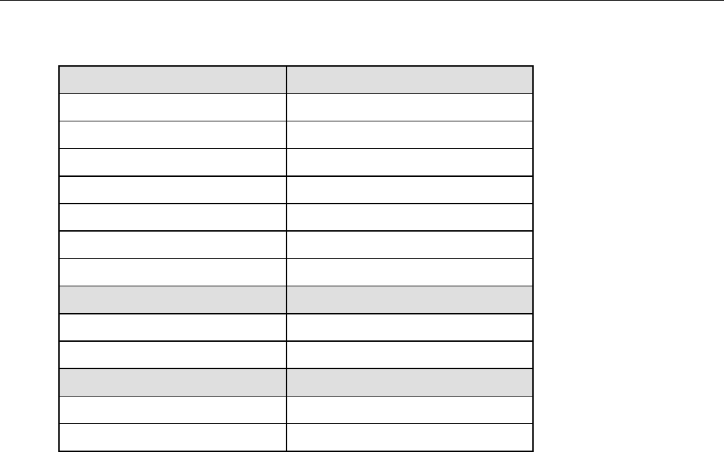
Teledyne API Model 200AH NOX Analyzer Instruction Manual, 06492, Rev. G2
5-33
Table 5-13: RS-232 Command Summary
Terminal Mode Editing Keys Definition
V MODE Print current analyzer mode
BS Backspace
ESC Erase line
^R Recall last command
^E Execute last command
CR Execute command
^C Switch to computer mode
Computer Mode Editing Keys Definition
LF Execute command
^T Switch to terminal mode
Security Features Definition
LOGON password Establish connection to analyzer
LOGOFF Disconnect from analyzer
General Output Message Format
Reporting of status messages for use as an audit trail is one of the two principal uses for the
RS-232 interface. You can effectively disable the asynchronous reporting feature by setting the
interface to quiet mode, see Table 5-9. All messages output from the analyzer (including those
output in response to a command line request) have the format:
X DDD:HH:MM IIII MESSAGE
X is a character indicating the message type, as shown in Table 5-14.
DDD:HH:MM is a time-stamp indicating the day-of-year (DDD) as a number from 1 to 366, the
hour of the day (HH) as a number from 00 to 23, and the minute (MM) as a number from 00
to 59.
IIII is the 4-digit machine ID number.
MESSAGE contains warning messages, test measurements, DAS reports, variable values, etc.
The uniform nature of the output messages makes it easy for a host computer to parse them.

Teledyne API Model 200AH NOX Analyzer Instruction Manual, 06492, Rev. G2
5-34
Table 5-14: RS-232 Interface Command Types
First Character Message Type
C Calibration status
D Diagnostic
R DAS report
T Test measurement
V Variable
W Warning
There are 6 different types of messages output by the M200AH. They are grouped below by type
in Table 5-15 – Table 5-19. The meanings of the various messages are discussed elsewhere in the
manual. The TEST, DIAGNOSTIC and WARNING messages are discussed in Sections 9.1.1,
9.1.2, 9.1.3. DAS and VARIABLES are discussed in Sections 5.3.3 and 5.3.9. CALIBRATE is
discussed in Section 7.

Teledyne API Model 200AH NOX Analyzer Instruction Manual, 06492, Rev. G2
5-35
5.7.3. TEST Commands and Messages
Table 5-15: RS-232 Test Messages
Name Message Description
NOXRANGE1 NOX RNG=xxxxx ppm Indep. range for NOx channel
NORANGE(1) NO RNG=xxxxx ppm(3) Indep. range for NO channel
NO2RANGE(1) NO2 RNG=xxxxx ppm(3) Indep. range for NO2 channel
RANGE(2) RANGE=xxxxx ppm(3) Analyzer range
STABIL STABIL=xxxx.xx ppm Std. Deviation of last 10 min of conc values
FLOW SAMPLE FL=xxx CC/M Sample flow rate
OFLOW OZONE FL=xxxx CC/M Ozone flow rate
PMT PMT=xxxxxx MV PMT output
NORM PMT NORM_PMT=xxxxxxx MV PMT output adjusted for T/P compensation
AZERO AZERO=xxxxxx MV AutoZero offset value
HVPS HVPS=xxxxx V High voltage power supply
DCPS DCPS=xxxxxx MV DC power supply
RCTEMP RCELL TEMP=xxx C Reaction cell temperature
BOXTEMP BOX TEMP=xxx C Internal box temperature
PMTTEMP PMT TEMP=xxx C PMT temperature
BLOCKTEMP BLOCK=xxx C Sample flow control block temp
CONVTEMP CONV TEMP=xxx C Converter temperature
RCPRESS RCEL=xxx.x IN-HG-A Rx Cell Pressure
SMPPRESS SAMP=xxx.x IN-HG-A Sample Pressure
NOXSLOPE NOXSLOPE=xxxxx NOX Slope Parameter
NOXOFFSET NOXOFFS=xxxxx NOX Offset Parameter
NOSLOPE NOSLOPE=xxxxxx NO Slope Parameter
NOOFFSET NOOFFS=xxxxxx NO Offset Parameter
CLKTIME TIME=HH:MM:SS Time of day
(1)Displayed when independent range is enabled.
(2)Displayed when single or AutoRange is enabled.
(3)Depends on which units are currently selected.

Teledyne API Model 200AH NOX Analyzer Instruction Manual, 06492, Rev. G2
5-36
The T command lists TEST messages. Examples of the T command are:
T LIST Lists test messages currently enabled with T SET
T LIST ALL Lists all test messages
T CONVTEMP Prints the temperature of the converter
T LIST NOX Prints NOx concentration message
T NOX Prints concentration message
5.7.4. WARNING Commands and Messages
Table 5-16: RS-232 Warning Messages
Name Message Description
WSYSRES SYSTEM RESET Analyzer was reset/powered on
WRAMINIT RAM INITIALIZED RAM was erased
WSMPFLOW SAMPLE FLOW WARN Sample flow out of spec.
WOZONEFLOW OZONE FLOW WARNING Ozone flow out of spec.
WRCELLP RCELL PRESS WARNING Rx cell pressure out of spec.
WBOXTEMP BOX TEMP WARNING Box temp. out of spec.
WRCELLT RCELL TEMP WARNING Reaction cell temp. out of spec.
WCONVTMP CONV TEMP WARNING Converter temp. out of spec.
WOBLKTMP ORIFICE BLK TEMP WARN Orifice block temp out of spec.
WDCPS DC POWER SUPPLY WARN DC Power voltage out of spec.
WDYNZERO CANNOT DYN ZERO Dynamic zero cal. out of spec.
WDYNSPAN CANNOT DYN SPAN Dynamic span cal. out of spec.
WBLKTEMP SAMPLE FLOW ORIFICE
BLOCK TEMP WARNING Temperature out of spec.
WOZONEGEN OZONE GEN OFF Ozone generator is off
WAUTOZERO AZERO WRN XXX.X MV AutoZero reading out of spec.
WADINS A/D NOT INSTALLED A/D board not installed or broken
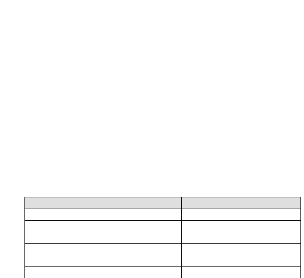
Teledyne API Model 200AH NOX Analyzer Instruction Manual, 06492, Rev. G2
5-37
Whenever a warning message is reported on the analyzer display, if the RS-232 interface is in
the normal mode(i.e. not in quiet mode) the warning message is also sent to the RS-232
interface. These messages are helpful when trying to track down a problem with the analyzer and
for determining whether or not the DAS reports are actually valid. The warning message format
is for example:
W 194:11:03 0000 SAMPLE FLOW WARN
The format of a warning command is W command. Examples of warning commands are:
W LIST List all current warnings
W CLEAR ALL Clear all current Warnings
Individual warnings may be cleared via the front panel or the command line interface. To clear
the sample flow warning shown above the command would be:
W WSMPFLOW
5.7.5. CALIBRATION Commands and Messages
Table 5-17: RS-232 Calibration Messages
Message Description
START ZERO CALIBRATION Beginning zero calibration
FINISH ZERO CALIBRATION, NO2=xxxxx ppm(1) Finished zero calibration
START SPAN CALIBRATION Beginning span calibration
FINISH SPAN CALIBRATION, NO2=xxxxx ppm(1) Finished span calibration
START MULTI-POINT CALIBRATION Beginning multi-point calibration
FINISH MULTI-POINT CALIBRATION Finished multi-point calibration
(1)Depends on which units are currently selected.
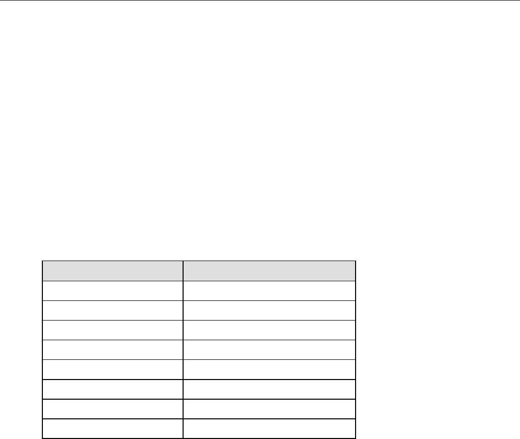
Teledyne API Model 200AH NOX Analyzer Instruction Manual, 06492, Rev. G2
5-38
Whenever the analyzer starts or finishes a calibration, it issues a status report to the RS-232
interface. If the RS-232 interface is in the normal mode, these reports will be sent. Otherwise,
they will be discarded. The format of these messages is:
C DDD:HH:MM IIII CALIBRATION STATUS MESSAGE
An example of an actual sequence of calibration status messages is:
C DDD:HH:MM IIII START MULTI-POINT CALIBRATION
C DDD:HH:MM IIII FINISH MULTI-POINT CALIBRATION
There are several methods of both checking the calibration and calibrating the M200AH, these
are discussed in Section 7. C LIST lists the calibration commands available. The C command
executes a calibration command, which may be one of the following:
Table 5-18: RS-232 Calibration Commands
Command Description
C LIST List calibration commands
C ZERO Enter zero calibration mode
C SPAN Enter span calibration mode
C COMPUTE ZERO Do a zero calibration
C COMPUTE SPAN Do a span calibration
C EXITZ Exit zero calibration
C EXITS Exit span calibration
C EXIT Exit zero or span calibration
5.7.6. DIAGNOSTIC Commands and Messages
When Diagnostic mode is entered from the RS-232 port, the diagnostic mode issues additional
status messages to indicate which diagnostic test is currently selected. Examples of Diagnostic
mode messages are:
D DDD:HH:MM IIII ZERO VALVE=ON
D DDD:HH:MM IIII ENTER DIAGNOSTIC MODE
D DDD:HH:MM IIII EXIT DIAGNOSTIC MODE

Teledyne API Model 200AH NOX Analyzer Instruction Manual, 06492, Rev. G2
5-39
The following is a summary of the Diagnostic commands.
Table 5-19: RS-232 Diagnostic Command Summary
Command Description
D LIST Prints all I/O signal values. See Table 9-4 for Sig I/O definitions.
D NAME=VALUE Examines or sets I/O signal. Must issue D ENTER SIG command
before using this command.
D LIST NAMES Prin is command.ts names of all diagnostic tests.
D ENTER SIG
D ENTER OT
D ENTER ET
Executes SIGNAL I/O diagnostic test.
Executes Optic Test diagnostic test.
Executes Elect Test diagnostic test.
Use D EXIT to leave these diagnostic modes.
D EXIT Must use this command to exit SIG, ET or OT Diagnostic modes.
D SYS_RESET Resets analyzer software (same as power on).
D RAM_RESET Resets analyzer software and erases RAM. Erases NO, NOX, NO2 conc
values, erases all DAS data. Keeps setup variables and calibration.
(Same as installing new software version.)
D EE_RESET Resets analyzer software and erases RAM and EEPROM. Returns all
setup variables to factory defaults, resets calibration values.
5.7.7. DAS Commands and Messages
The M200AH contains a flexible and powerful built in data acquisition system (DAS) that
enables the analyzer to store concentration data as well as diagnostic parameters in its battery
backed memory. This information can be printed out through the RS-232 port. The diagnostic
data can be used for performing “Predictive Diagnostics” and trending to determine when
maintenance and servicing will be required.
To print out the properties of all of the data channels enter:
D PRINT
To print the properties of just a single data channel enter:
D PRINT "name”
For example to print the properties of the CONC data channel enter:
D PRINT “CONC”

Teledyne API Model 200AH NOX Analyzer Instruction Manual, 06492, Rev. G2
5-40
To print records from a DAS data channel enter:
D REPORT “name” RECORDS=nnn COMPACT|VERBOSE
Examples of reports are:
D REPORT “CONC” RECORDS=35 VERBOSE
D REPORT “CALDAT” RECORDS=10
D REPORT “PNUMTC” RECORDS=155 VERBOSE
Automatic RS-232 reporting can be independently enabled and disabled for each Data Channel.
For all default data channels, automatic reporting is initially set to “OFF.” If this property is
turned on, the Data Channel will issue a report with a time and date stamp to the RS-232 port
every time a data point is logged. The report format is shown below:
D 94:08:00 0200 CONC : AVG NXCNC1 = 1234.5 PPB
D 94:08:00 0200 CONC : AVG NOCNC1 = 1234.5 PPB
D 94:08:00 0200 CONC : AVG N2CNC1 = 1234.5 PPB
One CONC report consists of:
D = Type of report (Diagnostic)
94:08:00 = Time and Date stamp (Julian day, Hr, Min)
0200 = Instrument ID number
CONC = Data Channel name
CONC = concentration data
PNUMTC = pneumatic parameters
CALDAT = calibration parameters
AVG = Type of data
AVG = average reading
INST = instantaneous reading
NXCNC1 = 1234.5 PPB = Name of the parameter
NX = NOX
NO = NO
N2 = NO2

Teledyne API Model 200AH NOX Analyzer Instruction Manual, 06492, Rev. G2
5-41
All of the default Data Channels sample more than one parameter, for these channels, each
parameter is printed on a separate line.
There is also a compact format. If this attribute is enabled, all 3 concentration parameters are
printed on one line as shown below:
D 94:08:00 0200 CONC : 120.0 100.0 20.0
The parameters are in the order of NOX, NO, and NO2.
To change any of the attributes of a particular data channel, the channel attributes are edited
from the front panel. The following table uses the example of Automatic Reporting. Other
attributes can be edited in a similar fashion.
5.7.8. VARIABLES Commands and Messages
The M200AH operational modes are listed above. To list the analyzer's current mode type:
V MODE Lists M200AH current operational mode
See Table 5-7 for list of operational modes and meanings.
Model M200AH Internal variables
The M200AH has a number of internal setup variables. Essentially all of these are set at time of
manufacture and should not need to be changed in the field. A list of user accessible variables is
shown in Table 9-5.
A list of variables and their settings can be requested over the RS-232 port by:
V LIST Lists internal variables and values
The output from this command is quite long and will not be shown here. The general format of
the output is:
name = value warning_lo warning_hi <data_lo> <data_hi>

Teledyne API Model 200AH NOX Analyzer Instruction Manual, 06492, Rev. G2
5-42
Where:
name = name of the variable
value = current value of variable
warning_lo = lower limit warning (displayed if applicable)
warning_hi = upper limit warning (displayed if applicable)
data_lo = lower limit of allowable values
data_hi = upper limit of allowable values
Variables can be changed. Before changing the settings on any variables, please make sure you
understand the consequences of the change. We recommend you call the factory before changing
the settings on any variables. The general format for changing the settings on a variable is:
V LIST name[=value [warn_lo [warn_hi]]]
For example to change the warning limits on the box temperature type:
V BOX_SET 30 10 50
and the CPU should respond with:
V DDD:HH:MM IIII BOX_SET=30 10 50(0-60)
The CONFIG command lists the software configuration.
For example:
V CONFIG list software configuration
The format of this listing is shown in the example below.
CONFIG[0] = Revision H.7
CONFIG[1] = NOx Analyzer
CONFIG[2] = SBC40 CPU

Teledyne API Model 200AH NOX Analyzer Instruction Manual, 06492, Rev. G2
6-1
6. OPTIONAL HARDWARE AND SOFTWARE
Optional equipment offered with the M200AH includes:
1. Rack mount with slides
2. Rack mount without slides, ears only
3. Rack mount for external pump
4. Stainless Steel zero/span valves*
5. Oxygen Sensor*
6. 4-20mA, isolated outputs
7. Molybdenum Converter
8. Model 501 External Stainless Steel/Molybdenum Converter
9. External Desiccant Canister
10. Alternate Bypass Flow Orifice - 500 cc/min
*Note: Zero/Span Valves and an Oxygen Sensor cannot be installed in the same instrument.
6.1. Rack Mount Options
Rack Mount including slides and ears, permits the Analyzer to be mounted in a standard 19"
wide x 24" deep RETMA rack. This permits convenient slide out operation for servicing. It can
also be ordered without slides for applications requiring the instrument to be rigidly mounted in
a RETMA rack.
The external pump can be ordered in the following configurations:
1. External pump pack - this configuration comes standard with the M200AH.
2. Pump Pack with rack mount - fixed tray.
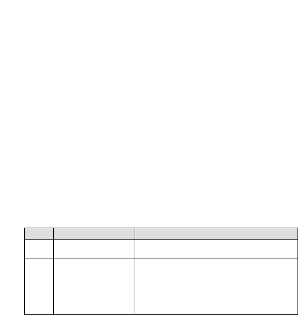
Teledyne API Model 200AH NOX Analyzer Instruction Manual, 06492, Rev. G2
6-2
6.2. Zero/Span Valves Option
The Zero/Span Valve option consists of a manifold of stainless steel valves plus drive electronics
connected to the CPU. The Option consists of two variations. Option 50 has 2 - 2-way valves,
1 3-way valve and operates in 3 modes:
1. Sample mode, all 3 valves off, sample gas flows through the sample port to the instrument.
2. Zero mode, sample-cal valve is energized to shut off sample flow, zero valve is energized to
input zero gas.
3. Span mode, sample-cal valve is energized to shut off sample flow, span valve is energized to
input low concentration range span gas.
Option 52 consists of all of the features in Option 50 plus a second span valve to allow a low and
high concentration of span gas.
See
Figure 2-6 for valve location. Fittings on the rear panel are for two concentrations of span gas
plus zero gas. (See Figure 2-2 and Figure 2-4) The valves are can be operated by several
methods shown in Table 6-1.
Note: The Zero/Span Valves option cannot be included in an instrument that also includes an Oxygen
Sensor.
Table 6-1: Zero/Span Valve Operation
Mode Description Reference Section
1. Front panel operation via
CALS and CALZ buttons Calibration Section 7 - Manual Zero/Span Check
2. Automatic operation using
AUTOCAL Setup and use of AUTOCAL is described in Table 6-2 and
Section 7.2
3. Remote operation using the
RS-232 interface Setup described in Section 6.2 Operation of AUTOCAL
described in Section 7.2
4. Remote operation using
external contact closures Section 7.5 - Automatic operation using external contact
closures. Table 7-12 and Section 9.3.4.3
Zero and span gas inlets should supply their respective gases in excess of the demand of the
Analyzer. Supply and vent lines should be of sufficient length and diameter to prevent back
diffusion and pressure effects. See Figure 2-4 for fitting location and tubing recommendations.
Note that Zero/Span Valves cannot be included in an instrument that also includes the Oxygen
sensor option.

Teledyne API Model 200AH NOX Analyzer Instruction Manual, 06492, Rev. G2
6-3
6.2.1. Autocal - Setup Zero/Span Valves
The Zero/Span valves can be set up to operate automatically. Table 6-2 in this section describes
Autocal setup.
Table 6-2: Setup Automatic Zero/Span Checking or Calibration
Step Action Comment
1. Press SETUP-ACAL This button sequence will cause the AUTOCAL menu to be displayed.
2. Press PREV or
NEXT This selects a SEQUENCE. Up to 3 Sequences can be defined. A
Sequence is a definition of zero/span calibrations along with timing
information.
3. Select MODE, then
PREV or NEXT MODE allows you to select the order of zero, low-span or high-span
that will be performed, MODES are listed in Table 6-3. Use PREV -
NEXT to scroll the list of choices, then press ENTR to select. To
disable a sequence, select DISABLE from the menu.
4. Press SET This menu sets up several timers and selects calibration or calibration
check.
1. TIMER ENABLE – If set to ON, the defined sequence will
execute. If set to OFF, the sequence will remain in memory, but
will not execute.
2. START DATE - calendar date to start sequence dd-mmm-yy, day-
month-year format.
3. START TIME - time of day sequence will start. hh-mm, hours-
minutes in 24 hr format.
4. DELTA DAYS and DELTA HOURS:MIN is the time between
each activation of the sequence. By setting the Delta Hours
variable to be other than an exact number of days, the sequence
can move ahead or be delayed each time it is run. For example, by
setting DELTA DAYS = 1 and DELTA HOURS = 1:00, the
sequence will execute 1 hour later each day. To set it to move back
½ hour each day, DELTA DAYS = 0, DELTA HOURS = 23:30.
5. DURATION -Amount of time for each zero/span point.
6. CALIBRATE – If set to ON, will calibrate(adjust slope and
offset). If OFF will check, but not change calibration.
7. 7. RANGE-TO-CAL Selects the range to calibrate LO or HI.
Applicable to AutoRange and RemoteRange modes.
5. Press EXIT The M200AH now exits the AUTOCAL SETUP menu. For each
enabled sequence, the M200AH will now AUTOCAL at the defined
times.

Teledyne API Model 200AH NOX Analyzer Instruction Manual, 06492, Rev. G2
6-4
Table 6-3: Action of MODE Field in AutoCal
MODE CALIBRATE = ON CALIBRATE = OFF
ZERO Zero calibrates LO or HI (depending
on RANGE-TO-CAL), SINGLE or
IND ranges.
Zero checks LO or HI (depending on
RANGE-TO-CAL), SINGLE or IND
range.
ZERO-LO Zero and low span calibrates LO,
SINGLE or IND ranges. Zero and low span checks LO, SINGLE
or IND ranges.
ZERO-HI Zero cals & span cals HI, SINGLE or
IND range with HI span gas. Zero checks & span checks on HI,
SINGLE or IND range with HI span
gas.
ZERO-LO-HI Zero cals, span cals LO and HI range.
LO span gas for LO range, HI span
gas for HI range.
Zero cals & span cals in SINGLE or
IND range using HI span gas. LO
span is cal check only.
Zero checks, span checks both ranges.
LO span gas for LO range, HI span gas
for HI range. Does 3 point check in
SINGLE or IND range modes.
LO-HI Span cals LO range with LO span gas,
Span cals HI range with HI span gas
in AutoRange mode. Span cals
SINGLE or IND range with HI span
gas. LO span is cal check only.
Span checks LO range with LO span
gas, Span checks HI range with HI span
gas. Does 2 point check in SINGLE or
IND range mode.
LO Span cals LO range with LO span gas.
Span cals SINGLE or IND range with
LO span gas.
Span checks LO range with LO span
gas. Span checks SINGLE or IND range
with LO span gas.
HI Span cals on HI range with HI span
gas. Span cals SINGLE or IND range
with HI span gas.
Span checks on HI range with HI span
gas. Span checks SINGLE or IND range
with HI span gas.
6.3. Oxygen Sensor Option
The Model 200AH can be equipped with an optional paramagnetic oxygen sensor that is capable
of measuring full scale ranges from 5% to 100%. The option consists of the paramagnetic sensor
module, an interface electronics board, a flow control orifice that generates a flow of about
80 cc/min through the sensor, and a temperature controlled oven that maintains the sensor and
flow control orifice at 50C.
Note that an Oxygen Sensor cannot be included in an instrument that also includes the Zero/Span
Valves option.

Teledyne API Model 200AH NOX Analyzer Instruction Manual, 06492, Rev. G2
6-5
6.4. Isolated 4-20 mA Current Loop Option
The M200AH comes equipped with 4-20mA current loop. The electrical ground of this output is
part of the instrument ground. In certain applications the instrument ground must be isolated
from the external ground. For applications requiring electrical isolation, we offer optional
isolated current loop outputs. With the exception of electrical isolation, the setup and usage is
identical to the standard equipment current loop output. The calibration procedure is located in
the Troubleshooting Section 9.
6.5. Molybdenum Converter Option
The Molybdenum Converter is used in applications where the NO2 concentration will not be
expected to exceed 5 ppm. In these applications it exhibits very high conversion efficiencies,
thus enabling the accurate measurement of low concentrations of NO2. Operating the Converter
where the concentrations exceed 5 ppm will cause lower efficiencies and will shorten the life of
the converter.
6.6. External Desiccant Canister Option
This Option is located between the PermaPure Dryer and the ozone flowmeter. See Figure 2-2
for location and Figure 8-5 for pneumatic schematic. It is mounted external to the analyzer. It
should be used at extremely humid sites, or where the -70°C dewpoint air produced helps in
reducing reaction cell contamination and window clouding.
6.7. Alternate Bypass Flow Orifice Option
The standard bypass flow is 250 cc/min. For those applications requiring a higher
sample flow, this option provides a 500 cc/min bypass flow. The overall sample flow is
550 cc/min with this option installed. The orifice is located in the vacuum manifold at
the rear of the instrument see
Figure 2-6.
6.8. M501 External Converter Option
The M200AH can be ordered with a Model 501 Thermal Converter. Its conversion performance
is very similar to the Mini HiCon. The advantage of this converter is that it is less prone to
plugging because it is constructed of larger diameter tubing, also the conversion efficiency is
very high because the thermal converter is followed by a molybdenum converter. Since the
converter is external to the M200AH the response of the instrument is considerably slower if
operated in the NO/NOX switching mode. This is due to the larger internal volume that must be
purged during the NO/NOX measurement cycle. This effect is less noticeable if the M200AH is
being operated in the NOX only mode.

Teledyne API Model 200AH NOX Analyzer Instruction Manual, 06492, Rev. G2
6-6
The M501 contains 2 converters, a high temperature stainless steel and a molybdenum converter.
While this combination produces very high conversion efficiencies, the life of the moly must be
considered. If high levels of NO2 are expected in the sample stream, the high temperature
converter converts only about 90 % of the total NO2, the moly must convert the rest. Since the
moly operates by reacting the molybdenum metal with the NO2, its lifetime can be quite short if
high levels (>50 ppm) of NO2 are present.
In instruments that have the external converter option, the Mini HiCon housing assembly
contains only the catalytic ozone killer and a heater to keep the ozone catalyst temperature at
200°C. Its temperature is monitored in the TEST function O3KL.

Teledyne API Model 200AH NOX Analyzer Instruction Manual, 06492, Rev. G2
7-1
7. CALIBRATION AND ZERO/SPAN CHECKS
There are several ways to check and adjust the calibration of the M200AH. These different
methods are summarized in the following Table 7-1. In addition, all of the methods described in
this section can be initiated and controlled via the RS-232 port, see Section 5.7 for details.
We strongly recommend that NOX SPAN CALIBRATION be done with NO span gas. Since NO
is unaffected by the converter, both channels can be accurately calibrated. It is also important
that there be some oxygen in the span gas. Inaccurate calibration of the NOX channel can result
from calibration gasses containing no oxygen. All calibration gasses must have a dew point of
< 20C.
NOTE
The quality of calibration can be no better than the accuracy and
quality of the calibration gasses used. See Section 7.10 Calibration
Quality for recommendations on calibration gasses and Section 9.2.10.
NOTE
If there are any problems completing any of the following procedures,
refer to Section 9.2.8 and 9.2.9- Unable to Span or Zero.
Before Calibration
1. Use the SETUP-RNGE menu to set the range the instrument will be operated in.
2. If you are using any of the following features, they must be set up before calibration:
A. Autoranging or Remote Ranging - See Section 7.8
B. Independent Ranges - See Section 7.9
C. NO only or NOX only mode, Section 7.6 and 7.7
Normal calibration assumes that these features are already set up.

Teledyne API Model 200AH NOX Analyzer Instruction Manual, 06492, Rev. G2
7-2
Table 7-1: Types of Zero/Span Check and Calibration
Section Type of Cal or Check Description
7.1 Manual Z/S Check or Calibration
with span gas in the sample port This calibration method uses calibration gas coming
in through the sample port. Zero/Span valves do not
operate.
7.2 Manual Z/S Check or Calibration
with Z/S Valve Option How to operate Zero/Span Valves Option. Can be
used to check or adjust calibration.
7.4 Dynamic Z/S Calibration with
Z/S Valves Option Operates Z/S valves periodically and adjusts
calibration.
7.5 Use of Z/S Valves with Remote
Contact Closure Operates Z/S valves with rear panel contact closures.
Without valves, can be used to switch instrument into
zero or span cal mode. Used for either checking or
adjusting zero/span.
7.6 NO Only Mode Calibration Covers requirements if calibrating in NO only mode.
7.7 NOx Only Mode Calibration Covers requirements if calibrating in NOx only mode.
7.8 Calibration Requirements for
AutoRange or Remote range Covers special requirements if using AutoRange or
Remote Range control.
7.9 Calibration Requirements for
Independent Ranges Covers special requirements if using Independent
Range.
7.10 Calibration Quality Information on how to determine if the calibration
performed will result in optimum instrument
performance.
7.11 Converter Efficiency
Compensation Covers methods to automatically compensate for
converter efficiency.

Teledyne API Model 200AH NOX Analyzer Instruction Manual, 06492, Rev. G2
7-3
7.1. Manual NOX Zero/Span Check or Cal With Zero/Span
Gas in the Sample Port
The calibration of the instrument can be checked or adjusted using gas coming in the sample
port. This method is often used when the calibration gas is supplied from the stack sample probe
or external tank and valve system. This is the calibration method to use if the instrument is
purchased without the Zero/Span Valve.
Table 7-2 details the zero calibration procedure with zero gas coming in through the sample port.
Table 7-2: Manual Zero Calibration Procedure - Zero Gas Thru Sample Port
Step Number Action Comment
1. Check “Before
Calibration” Check “Before Calibration” Section 7 above before
proceeding.
2. Press CAL The M200AH enters the calibrate mode from sample mode.
The zero gas must come in through the sample port.
3. Select LO or HI
Range If AutoRange is enabled you will be prompted for which
range to calibrate. Select the LO or Hi range, then press
ENTR.
4. Wait 10 min Wait for reading to stabilize at zero value.
5. Press ZERO If you change your mind after pressing ZERO, you can still
press EXIT here without zeroing the instrument.
6. Press ENTR Pressing ENTR actually changes the calculation equations.
7. Press EXIT M200AH returns to sampling. Immediately after calibration,
data is not added to the DAS averages.

Teledyne API Model 200AH NOX Analyzer Instruction Manual, 06492, Rev. G2
7-4
Enter the expected NOx and NO span gas concentrations:
Table 7-3: Enter Expected Span Gas Concentrations Procedure
Step Number Action Comment
1. Check “Before
Calibration” Check “Before Calibration” Section 7 before proceeding.
2. Press
CAL-CONC-
NOX
This key sequence causes the M200AH to prompt for the
expected NOX concentration.
Enter the NOX span concentration value by pressing the key
under each digit until the expected value is set. This menu
can also be entered from CALS or CALZ.
3. Press ENTR Pressing ENTR stores the NO span value and returns the
prompt to the CONC menu.
4. Press
CAL-CONC-NO This key sequence causes the M200AH to prompt for the
expected NO concentration.
Enter the NO span concentration value by pressing the key
under each digit until the expected value is set. This menu
can also be entered from CALS or CALZ
5. Press ENTR Pressing ENTR stores the NO span value and returns the
prompt to the CONC menu.
6. Press EXIT Returns instrument to SAMPLE mode.
If desired, compensation for converter efficiency (CE) can be included in the NOx and NO2
concentration calculation. The CE must be entered prior to calibration. Refer to Section 7.10 for
the CE procedure.

Teledyne API Model 200AH NOX Analyzer Instruction Manual, 06492, Rev. G2
7-5
Table 7-4: Manual Span Calibration Procedure - Span Gas Thru Sample Port
Step Number Action Comment
1. Press
CAL-CONC-NO This key sequence causes the M200AH to prompt for the
expected NO concentration.
Enter the NO span concentration value by pressing the key
under each digit until the expected value is set. This menu
can also be entered from CALS or CALZ.
2. Press ENTR Pressing ENTR stores the NO span value and returns the
prompt to the CONC menu.
3. Press CAL The M200AH enters the calibrate mode. NO span gas should
be fed to the sample port.
4. Select LOW or
HIGH If AutoRange is selected, it is necessary to select which range
to calibrate. This prompt will not be displayed unless
Autorange or Remote range is selected.
5. Wait 10 min Wait for reading to stabilize at span value.
6. Press SPAN If you change your mind after pressing SPAN, you can still
press EXIT here without spanning the instrument.
7. Press ENTR Pressing ENTR actually changes the calculation equations
and causes the instrument to read the expected NO and NOX
span concentrations.
8. Press EXIT M200AH returns to sampling. Immediately after calibration,
data is not added to the DAS averages.

Teledyne API Model 200AH NOX Analyzer Instruction Manual, 06492, Rev. G2
7-6
7.2. Manual O2 Zero/Span Check or Cal With Zero/Span
Gas in the Sample Port
The calibration of the O2 Sensor can be checked or adjusted using gas coming in the sample port.
This method is often used when the calibration gas is supplied from the stack sample probe or
external tank and valve system.
Table 7-5 details the zero calibration procedure with zero gas coming in through the sample port.
Table 7-5: Manual O2 Zero Calibration Procedure - Zero Gas Thru Sample Port
Step Number Action Comment
1. Check “Before
Calibration” Check “Before Calibration” Section 7 above before
proceeding.
2. Press
CAL-O2-ENTR The M200AH enters the calibrate mode for O2. The zero gas
must come in through the sample port.
4. Wait 10 min Wait for reading to stabilize at zero value.
5. Press ZERO If you change your mind after pressing ZERO, you can still
press EXIT here without zeroing the instrument.
6. Press ENTR Pressing ENTR actually changes the calculation equations.
7. Press EXIT M200AH returns to sampling. Immediately after calibration,
data is not added to the DAS averages.
Table 7-6 details the span calibration procedure with span gas coming in through the sample
port.

Teledyne API Model 200AH NOX Analyzer Instruction Manual, 06492, Rev. G2
7-7
Table 7-6: Manual O2 Span Calibration Procedure - Span Gas Thru Sample Port
Step Number Action Comment
1. Press
CAL-O2-CONC This key sequence causes the M200AH to prompt for the
expected O2 concentration.
Enter the O2 span concentration value by pressing the key
under each digit until the expected value is set.
2. Press ENTR Pressing ENTR stores the O2 span value and returns the
prompt to the CAL menu.
3. Wait 10 min Wait for reading to stabilize at span value.
4. Press SPAN If you change your mind after pressing SPAN, you can still
press EXIT here without spanning the instrument.
5. Press ENTR Pressing ENTR actually changes the calculation equations
and causes the instrument to read the expected O2 span
concentration.
6. Press EXIT M200AH returns to sampling. Immediately after calibration,
data is not added to the DAS averages.
7.3. Manual Zero/Span Check with Zero/Span Valves
Option
The Zero/Span valve option can be operated from the front panel keyboard as described below.
The Zero/Span valves allow zero and span gas come in through ports on the rear panel of the
instrument. The Zero/Span valves can be set up to operate automatically on a periodic schedule.
See Section 6.2 to setup automatic zero/span feature.

Teledyne API Model 200AH NOX Analyzer Instruction Manual, 06492, Rev. G2
7-8
Table 7-7: Manual Zero Check Procedure - Z/S Valves
Step Number Action Comment
1. Check “Before
Calibration” Check “Before Calibration” Section 7 before proceeding.
2. Press CALZ The analyzer enters the zero calibrate mode. This switches the
sample/cal and zero valve to allow zero gas to come in
through the zero gas inlet port in the rear panel.
3. Select LO or HI
range If AutoRange is enabled you will be prompted for which
range to calibrate. Select the LO or HI range, then press
ENTR.
4. Wait 10 min Wait for reading to stabilize at zero value.
5. Press ZERO If you change your mind after pressing ZERO, you can still
press EXIT here without zeroing the instrument.
6. Press ENTR Pressing ENTR actually changes the calculation equations,
forcing the reading to zero.
7. Press EXIT M200AH returns to sample mode. Immediately after
calibration, readings do not go into the DAS averages.
Refer to Table 7-3 to enter expected NO and NOx values.

Teledyne API Model 200AH NOX Analyzer Instruction Manual, 06492, Rev. G2
7-9
Table 7-8: Manual Span Check Procedure - Z/S Valves
Step Number Action Comment
1. Press CALS The M200AH enters the span calibrate mode and switches the
Z/S valves to admit NO span gas.
2. Select LO or HI
range If AutoRange is enabled you will be prompted for which
range to calibrate. Select the LO or HI range, then press
ENTR.
3. Wait 10 min Wait for reading to stabilize at span value.
4. Press SPAN If you change your mind after pressing SPAN, you can still
press EXIT here without spanning the instrument.
5. Press ENTR Pressing ENTR actually changes the calculation equations
and causes the instrument to read the expected NO and NOX
span concentrations.
6. Press EXIT The Zero/Span valves are switched back to admit gas through
the sample port and instrument returns to SAMPLE mode.
Immediately after calibration, data is not added to the DAS
averages.
7.4. Dynamic Zero/Span Calibration Using AutoCal
The M200AH can be automatically calibrated periodically using the Zero/Span Valve Option
and features in the AUTOCAL menu. The Dynamic Zero/Span feature can be enabled when an
AutoCal Sequence is set up. Refer to Section 6.2 for information.
With the Dynamic AutoCal in operation, the M200AH is being continuously re-calibrated. We
recommend that the quality of the calibrations be carefully monitored to assure that the
instrument is performing correctly. Subtle fault conditions can sometimes be masked by
continuous re-calibration.

Teledyne API Model 200AH NOX Analyzer Instruction Manual, 06492, Rev. G2
7-10
7.5. Use of Zero/Span Valves with Remote Contact
Closure
The Zero/Span valve option can be operated using Remote Contact Closures provided on the rear
panel. See Figure 2-2 for connector location and pinout. There are 3 sets of contacts on the rear
panel. They operate the zero valve, LO span valve, and HI span valve. To operate the valves,
they must be held closed for at least 1 second. The valve will remain in operation for as long as
the contacts are closed. In order to operate the valves again, the contact closures should be held
open for at least 1 second, then may be closed again.
The default action is to do a span check when the valves are operated. A span check does not
calibrate the instrument when the valves are operated. To calibrate the M200AH when the valves
are operated, go to the VARS section on the front panel menus. Press SETUP-MORE-VARS,
then scroll to DYN_ZERO.
DYN_LO_SPAN or DYN_HIGH_SPAN, and set the variable to ON. With the variable in the
ON state, the M200AH will calibrate when the contact closure is released.
Table 7-9 shows what type of check is performed based on the settings of the three contact
closures.
Table 7-9: Z/S Valve Modes with Remote Contact Closure
External Zero
Contact Closure External LO Span
Contact Closure External HI Span
Contact Closure Operation
Open Open Open State when in SAMPLE mode,
normal monitoring.
Open Closed Open Low Span check or calibrate*
Open Open Closed High Span check or calibrate*
Closed Open Open Zero check or calibrate*
*Calibrate only if Dynamic Calibration Variable is ON

Teledyne API Model 200AH NOX Analyzer Instruction Manual, 06492, Rev. G2
7-11
7.6. NO Only Mode Calibration
For details on the operation of this mode, check Section 5.4. In NO only mode, the span check or
span calibration is operated using the same procedures covered in Sections 7.1 to 7.5. The main
difference to note is that only one channel, namely the NO channel will be checked or calibrated.
For example in Table 7-3 - Entering the Expected Span value, only the NO concentration is
required. The NO/NOx valve is continuously in the NO mode. And since the converter is never
switched into the sample gas stream, none of the converter efficiency procedures apply.
7.7. NOX Only Mode Calibration
For details on the operation of this mode, check Section 5.4. In NOX only mode, the span check
or span calibration is operated using the same procedures covered in Sections 7.1 to 7.5. The
main difference to note is that only one channel, namely the NOX channel, will be checked or
calibrated. For example in Table 7-3 - Entering the Expected Span value, only the NOX
concentration is required. The NO/NOX valve is continuously in the NOX mode.
Since the instrument is always in NOX mode it is not possible to apply converter efficiency
compensation to the NOX value. This is because the efficiency should only be applied to the NO2
portion of the signal. The valve never switches to measure the proportion of NO in the sample
gas, therefore the fraction of the sample that is NO2 is unknown.
It is recommended that the converter efficiency be measured when the instrument is calibrated.
This procedure is covered in Section 7.10.
7.8. Calibration Requirements for AutoRange or Remote
Range
In AutoRange there are two separate calibrations for Low range and High range. There are 2
independent slopes and 2 offsets and 2 sets of converter efficiency parameters. The instrument
applies the appropriate values depending on whether the instrument is in low range or high
range.

Teledyne API Model 200AH NOX Analyzer Instruction Manual, 06492, Rev. G2
7-12
Table 7-10: Calibration Requirements for AutoRange or Remote Range
No matter which calibration method you choose from this chapter, all of the following
parameters must be set to properly calibrate the instrument on AutoRange or Remote range.
Parameter Low Range High Range
Range Low Range is selected by pressing
CONC-LO on the front panel. High Range is selected by pressing
CONC-HI on the front panel.
Slope NOX and NO slopes for low range
are set by span calibration. NOX and NO slopes for high range
are set by span calibration.
Offset NOX and NO offsets for low range
are set by zero calibration. NOX and NO offsets for high range
are set by zero calibration.
Converter Efficiency CE can be set by one of the
procedures in Section 7.11.
Converter efficiency is optional.
CE can be set by one of the
procedures in Section 7.11.
Converter efficiency is optional.
7.9. Calibration Requirements for Independent Range
In Independent Range mode there is one set of calibration parameters. That is, NOX and NO
slopes and NOX and NO offsets, and one converter efficiency parameter. The calibration of the
M200AH using independent range is the same as calibration in single range. To achieve
independent ranges, the computer scales the 3 outputs using the ranges keyed in by the operator.
7.10. Calibration Quality
After calibration is complete, it is very important to check the QUALITY of the calibration. The
calibration of the M200AH involves balancing several sections of electronics and software to
achieve optimum accuracy, noise, linearity and dynamic range.
The slope and offset parameters are similar to the span and zero pots on an analog instrument.
Just as in the analog instrument, if the slope or offset get outside of a certain range, the
instrument will not perform as well.
The slope value will be slightly different on the NO and NOX channels. This is due to slight
differences in pneumatic resistance in each pathway. If the slopes are significantly different,
there is a calibration error or a cross port leak in the switching valve. If there is a sudden change
in slopes after a calibration, that usually indicates a change in reaction cell pressure. Check the
Troubleshooting Section 9.
The offset value gives information about the background signal level. Check the observed offset
value against the factory value in Table 2-1. If significantly higher, check Section 9.1.6.
Increasing readings are a predictor of problems.

Teledyne API Model 200AH NOX Analyzer Instruction Manual, 06492, Rev. G2
7-13
Table 7-11: Calibration Quality Check
Step
Number Action Comment
1. Scroll the TEST function
menu until the NOX
SLOPE is displayed.
The SLOPE value for NOX should be 1.0 0.3. If the value is
not in this range, check Section 9.1.6. If the SLOPE value is
in the acceptable range the instrument will perform optimally.
2. Scroll the TEST function
menu until the NOX
OFFSET is displayed.
This number should be near zero. A value of 0.0 50
indicates calibration in the optimal range. This number
already has the AutoZero value subtracted out and is mainly
the background signal due to the molybdenum converter. If
the OFFSET value is outside this range, check Section 9.1.6.
3. Scroll the TEST function
menu until the NO
SLOPE is displayed.
The SLOPE value for NO should be 1.0 0.3. If the SLOPE
is in the acceptable range the instrument will perform
optimally. If the value is not in this range, check
Section 9.1.6.
NOTE: The NO and NOX slopes should be equal within 0.1.
4. Scroll the TEST function
menu until the NO
OFFSET is displayed.
The instrument will now display the NO OFFSET value. It
should also have a value near zero (0.0 50). This number
already has the AutoZero reading subtracted out and should
be near zero. If the OFFSET value is outside this range, check
Section 9.1.6.
7.11. Converter Efficiency Compensation
The converter efficiency factor compensates NO2 readings for converter efficiency. The NO2
component of the NOX reading is also compensated when instrument is in switching mode. An
efficiency factor of 1.0 disables efficiency compensation, acceptable values are .80 to 1.20.
There are some fault conditions that can be revealed by a NO2 channel linearity check, such as a
faulty switching valve or a partially plugged converter. For the converter to operate properly
there should be at least a few percent oxygen present in the sample stream.
There are 2 ways to enter the NO2 converter efficiency.
Method 1 is covered in Table 7-12.

Teledyne API Model 200AH NOX Analyzer Instruction Manual, 06492, Rev. G2
7-14
Table 7-12: Converter Efficiency - Automatic Calculation
Step
Number Action Comment
1. Preparation Make sure a calibration is completed before setting up
Converter efficiency.
2. Press
CAL-CONC-CON-NO2 Enter the expected NO2 concentration, then press ENTR.
3. Input a known
concentration of NO2
calibration gas.
Allow reading to stabilize for 10 minutes.
4. Press CAL-ENTR By pressing ENTR the M200AH will calculate the ratio of
the observed to expected NO2 and will use that ratio to
compensate future NO2 readings. The calculated value can be
seen by pressing the SET button.
NOTE: The CAL button will come on only if the Instrument is
measuring NO2 gas and ratio is between the limits of 0.80 - 1.20.
5. Press EXIT EXIT will return instrument to SAMPLE mode.
Method 2. If the converter efficiency is determined by some external means, the value can be
directly entered. Press CAL-CONC-CON-SET, then key in the ratio and press ENTR, then
EXIT.
7.12. Recommendations for CEM Applications
7.12.1. Calibration Gasses
The following is our recommendation for calibration gasses and equipment for the M200AH.
Regulator Specifications:
Ultra high purity, two-stage stainless steel body with stainless steel diaphragms, Tefzel and
Teflon seats and seals, CGA 660 type. Gauges are 0-4000 psig inlet with 0-100 psig outlet.
Nitric Oxide Calibration Gas specifications:
Use NO in nitrogen, EPA protocol 1, NIST traceable (long lead item, order early) for CEMS
Certification Test gas and acid rain applications.
Use NO in nitrogen at 80% of calibration range 2% for routine calibration.
Example: Order 80 ppm NO in N2 if calibrating the 0-100 ppm range.

Teledyne API Model 200AH NOX Analyzer Instruction Manual, 06492, Rev. G2
7-15
NOTE
It is important to note that if you are using blended calibration gasses,
other components of the blend can interfere with the NO concentration
value. This can affect calibration accuracy and linearity. See
Section 9.2.10 for additional details.
Zero Air:
Ultra Zero Grade Air, 99.999% pure
Nitrogen:
Ultra High purity Nitrogen, 99.999% pure
7.12.2. Calibration Frequency
Typically, the data acquisition system will perform a daily calibration. This consists of switching
valves to have calibration gas introduced at the sample probe and passing through the entire
sample induction system. The instrument or data acquisition system’s slope and offset will be
adjusted to produce the correct response of the system.
Once per quarter, the M200AH should be calibrated using one of the procedures in Section 7.
Also a 3 point linearity check (zero, low span, high span) will be performed to confirm system
linearity.
It is important to note that when doing a linearity check, the calibration gasses have analysis
errors. For example if 2% standards are being used, the linearity could be theoretically be as
much as 4% in error, even if the instrument and sample induction system are “perfect”. Teledyne
API recommends that EPA Protocol 1 ( 1%) gasses be used for linearity checks to minimize
non-linear responses due to analysis errors of the gas bottles.
7.12.3. Converter Efficiency
In many applications the NO2 concentration is low enough (<5%) that converter efficiency
checks are not required. If your application requires an efficiency check, refer to 40 CFR, Part 60
Method 7E for the recommended procedure. Refer to Section 7.11 if automatic converter
efficiency compensation is required.

Teledyne API Model 200AH NOX Analyzer Instruction Manual, 06492, Rev. G2
7-16
THIS PAGE IS INTENTIONALLY LEFT BLANK
Teledyne API Model 200AH NOX Analyzer Instruction Manual, 06492, Rev. G2
8-1
8. MAINTENANCE
8.1. Maintenance Schedule
NOTE
The operations outlined in this chapter are to be
performed by qualified maintenance personnel only.
Table 8-1: Preventative Maintenance Schedule
Item Maintenance Interval Reference Section
TEST functions 6 - 12 month intervals Table 9-1
Zero/Span Calibration Annually or after repairs Section 7
Zero/Span checks Daily Section 7, Table 6-2
Particulate Filter Weekly as needed Figure 8-1
Filter for PermaPure Drier Replace every 24 months Figure 9-7
Filter for Ozone Scrubber Replace every 24 months Figure 4-
Drierite Canister Replace when Drierite changes
from blue to red. Section 9.3.6
Reaction cell window Clean annually or as necessary Section 9.3.8, Figure 8-3
Ozone Flow Check TEST function every
year Figure 9-7, Section 9.3.7
Sample Flow Check TEST function every
year Figure 8-4, Figure 8-5
Section 9.3.7
Converter Check efficiency every 6
months Figure 8-2, Section 7.10
Pneumatic Lines Examine every 12 months,
clean if necessary Figure 8-5, Figure 8-6
Factory Calibration Calibrate each year or after
repairs Sections 9.1.6
Leak Check Check every year or after other
maintenance. Sections 8.6, 9.3
Rx Cell O-rings Replace every 12 months Figure 8-3
O-rings Replace every 12 months Figure 9-9, Figure 9-10

Teledyne API Model 200AH NOX Analyzer Instruction Manual, 06492, Rev. G2
8-2
8.2. Replacing the Sample Particulate Filter
The particulate filter should be inspected often for signs of plugging or contamination. It is also
common for dirt particles to absorb NO2, thus causing the reading to be low. A discoloration of
the filter membrane indicates that the filter is dirty and should be changed.
To change the filter:
1. Locate the sample filter on the outside rear panel.
2. Unscrew the hold-down ring, remove the Teflon o-ring and then the filter disc. See
Figure 8-1 for an exploded view of the filter assembly.
3. Replace the filter, being careful that the element is fully seated in the bottom of the holder.
Replace the Teflon o-ring, then screw on the hold-down ring and hand tighten.
Teledyne API Model 200AH NOX Analyzer Instruction Manual, 06492, Rev. G2
8-3
Figure 8-1: Replacing the Particulate Filter

Teledyne API Model 200AH NOX Analyzer Instruction Manual, 06492, Rev. G2
8-4
8.3. Replacing the Converter
The Converter is located in the center of the instrument, refer to
Figure 2-6 for its location. The heater, thermocouple, ozone scrubber and converter are designed
to be replaced as a single unit.
1. Turn off the power to the M200AH and allow the converter to cool.
2. Remove the entire assembly from the chassis:
CAUTION
The converter operates at about 700°C. Severe burns can result if
not enough time is allowed for the assembly to cool. Do not
handle assembly until it is at room temperature.
A. Remove the pneumatic fittings from the valves.
B. Remove the Molex connectors to the valve bracket, thermocouple wire and cartridge
heater.
C. Remove the converter assembly from the chassis by loosening the 4 captive screws that
secure the assembly to the chassis.
3. Disconnect the gas fittings and power cable grounding from the can.
4. Remove the valve assembly and bottom bracket and re-attach those two parts to the
replacement converter assembly.
5. Re-attach the pneumatic fittings and valve assembly to the can.
6. Install the assembly back into the analyzer. Re-attach the electrical and pneumatic fittings.
Leak check the assembly when completed.
7. Turn the power back on. The insulation can emit a burnt odor for the first 24 hours, this is
normal. Allow the converter to burn-in for 24 hours, then re-calibrate the instrument.
Teledyne API Model 200AH NOX Analyzer Instruction Manual, 06492, Rev. G2
8-5
Figure 8-2: Converter Assembly

Teledyne API Model 200AH NOX Analyzer Instruction Manual, 06492, Rev. G2
8-6
8.4. Cleaning the Reaction Cell
The reaction cell should be cleaned whenever troubleshooting points to it as the cause of the
trouble. A dirty cell and window will cause excessive noise, unstable span or zero, or low
response. To clean the reaction cell it is necessary to remove the reaction cell from the sensor
housing. Use the following guide:
1. Turn off the instrument power and vacuum pump.
2. Loosen the hold down screws for pneumatic sensor assembly & move the assembly to the
side.
3. Disconnect the exhaust fitting and inlet fittings. See Figure 8-3.
4. Loosen four screws holding the reaction cell to the sensor.
5. Disconnect heater/thermistor and lift the cell away.
6. The reaction cell will separate into two halves:
A. The manifold assembly.
B. The reaction block with reaction sleeve and window.
7. Push the reaction sleeve and window gently out of the reaction cell. Clean the assembly with
any of the following:
A. Ammonia free glass cleaner.
B. Baking soda (sodium bicarbonate) and water solution.
C. Simple Green 10:1 dilution.
Rinse with distilled or de-ionized water, wipe with a clean tissue, and dry. It is normally
not necessary to clean the ozone flow or sample flow orifices because they are protected
by fritted filters. However, the following procedure is included here for completeness.
8. The manifold assembly should be cleaned by removing the o-ringed fittings, springs, fritted
filter, orifices and O-rings from the ozone inlet. (NOTE: That the sample inlet does not
contain a sample flow control orifice. The sample flow control orifice is located in a heated
block at the rear of the instrument.) It is suggested that the orifice, filter and o-rings be
replaced unless an ultrasonic cleaner and methanol or methylene chloride is available. Both
orifice and sintered filter may be cleaned in either solvent by an ultrasonic bath for 30
minutes. Replace o-rings.
9. Do not remove the sample and ozone nozzles. They are Teflon threaded and require a special
tool for re-assembly. If necessary, the manifold with nozzles attached can be cleaned in an
ultrasonic bath.
Teledyne API Model 200AH NOX Analyzer Instruction Manual, 06492, Rev. G2
8-7
10. Reassemble in the reverse order of disassembly, being sure to seat the paper gasket in the
reaction cell before installing the window. After inserting the window, drop the o-ring in
before inserting the sleeve. Reconnect pneumatics and heater connections, then re-attach the
pneumatic sensor assembly.
11. Perform leak check procedure covered in Section 8.6. Perform light leak procedure covered
in Section 8.7. The cleaning procedure is complete.
12. The analyzer span response will fall 10-12% in the first 1-2 days after cleaning due to the
window re-conditioning.
Figure 8-3: Reaction Cell Assembly
Teledyne API Model 200AH NOX Analyzer Instruction Manual, 06492, Rev. G2
8-8
Figure 8-4: Sample/Bypass Flow Control Assembly

Teledyne API Model 200AH NOX Analyzer Instruction Manual, 06492, Rev. G2
8-9
8.5. Pneumatic Line Inspection
Particulate matter in the pneumatic lines will affect both flow rate and response time. It is
important that the pneumatic system be periodically inspected and thoroughly cleaned if
necessary. Clean by disassembling and passing methanol through three times. Dry with nitrogen
or suitable clean zero air.
Also inspect all pneumatic lines for cracks and abrasion on a regular basis. Replace as necessary.
Refer to the pneumatic diagram in Figure 8-5, Figure 8-6.
Teledyne API Model 200AH NOX Analyzer Instruction Manual, 06492, Rev. G2
8-10
Figure 8-5: Pneumatic Diagram
Teledyne API Model 200AH NOX Analyzer Instruction Manual, 06492, Rev. G2
8-11
Figure 8-6: Pneumatic Diagram with Zero/Span Valves
Teledyne API Model 200AH NOX Analyzer Instruction Manual, 06492, Rev. G2
8-12
Figure 8-7: Pneumatic Diagram with Oxygen Sensor

Teledyne API Model 200AH NOX Analyzer Instruction Manual, 06492, Rev. G2
8-13
8.6. Leak Check Procedure
If a leak checker is not available, it is possible to leak check the instrument using the M200AH's
pump plus a shut-off valve.
1. Turn off instrument power and pump power.
2. Cap the sample inlet port, ozone generator air inlet, and zero air inlet (if Z/S valve option
present).
3. Insert a shut-off valve between the sample pump and the vacuum manifold at the rear of the
instrument.
4. Turn on the sample pump and set the TEST function to RCEL, which measures the reaction
cell pressure. Turn off the shutoff valve and monitor the cell pressure. The pressure should
not increase more than 1 PSI in 5 minutes.
If you have a leak checker:
1. Turn off instrument power and pump power.
2. Disconnect pump at rear panel. Cap the sample inlet port, ozone generator air inlet, and zero
air inlet (if Z/S valve option present) and connect leak checker to exhaust port.
CAUTION
Pressure must be less than 15 psi.
3. Pressurize system and check for leaks by watching overall pressure. The pressure should not
drop more than 1 “-Hg in 5 minutes (0.5 PSIG in 5 min).
If instrument fails pressure test, each fitting needs to be leak checked with soap solution to find
the location. Be careful that the system is always pressurized so as not to draw soap solution into
the plumbing system. Make sure you dry off any accumulated soap solution. Refer to Figure 8-4,
Figure 8-5 for pneumatic diagrams.
8.7. Light Leak Check Procedure
1. Scroll the TEST functions to PMT.
2. Input zero gas.
3. Shine a powerful flashlight or portable incandescent light at the inlet and outlet fitting, and at
all the joints of the reaction cell. The PMT value should not respond to the light.
If there is a response, tighten the joints or replace the tubing with new black PTFE tubing. We
often find light leaks are caused by o-rings being left out of the sensor assembly.

Teledyne API Model 200AH NOX Analyzer Instruction Manual, 06492, Rev. G2
8-14
8.8. Prom Replacement Procedure
Preparation: If any setup changes such as RANGE, AUTOCAL, ON/OFF etc. have been made,
record the changes because all settings should be checked after the PROM is changed. See
Figure 9-2 for location of prom on CPU card.
1. Turn the machine off.
NOTE
The PROM is static sensitive, be sure that you are properly
grounded before handling any of the electronics.
2. Remove the hold down screw that holds in the V/F-CPU assembly to the motherboard.
Disconnect the J9 power connector from the motherboard. Gently lift the assembly far
enough out of the instrument to remove the connector to the display and the RS-232
connector.
3. Locate the CPU board, which is attached to the larger V/F board.
4. Remove the CPU-V/F board assy, laying it down on an insulating surface such that the board
edge pins on the PCB are on the left. The PROM chip will be at the top center. See
Figure 9-2 for prom location. Gently pry the chip from its socket and replace it with the new
chip. Install the chip in the left end of the socket with the notch facing to the right. Make sure
that all of the legs insert into the socket correctly.
5. Re-attach the CPU board to the V/F board, re-connect the RS-232 and front panel display
cables, and then re-attach the assembly to the motherboard.
6. Turn the M200AH ON and observe the front panel display. As the machine goes through the
setup the version number will be displayed on the front panel. It should read the same as the
version number printed on the prom.
7. Check and re-enter if necessary any non-default settings such as RANGE or AUTOCAL. Re-
enter the SPAN value. Check all settings to make sure that expected setup parameters are
present.
8. Re-calibrate the machine so that the default slope and intercept are overwritten with the
correct values.
Teledyne API Model 200AH NOX Analyzer Instruction Manual, 06492, Rev. G2
9-1
9. TROUBLESHOOTING AND ADJUSTMENTS
NOTE
The operations outlined in this chapter are to be
performed by qualified maintenance personnel only.
This section of the manual contains information on diagnosing and repairing instrument
performance problems. It contains information on how to use and interpret TEST and
DIAGNOSTIC data as well as WARNING messages the instrument generates. There is
information on how to troubleshoot the instrument subsystems. Finally there is information on
how to perform adjustments such as DAC calibration procedures.
This manual provides troubleshooting procedures that address problems to the board level. For
component level troubleshooting, consult the schematics for the appropriate board in
Appendix A-1.
NOTE
The values of the readings shown on the front panel of the
instrument may at times read XXXXXX. This means that the
reading is off scale and therefore meaningless.
General Troubleshooting Hints
1. Think of the analyzer as three sections:
Section 1: Pneumatics - Over 50% of all analyzer problems are traced to leaks in the pump,
sample filter, instrument internal pneumatics, calibrator or external sample handling
equipment. Suspect a leak first, and check Section 9.2.
Section 2: Electronics - data processing section. This can be readily checked out using
Electric Test in Section 9.1.3.2.
Section 3: Optics - Optical section consisting of PMT, HVPS, Preamp, and signal
processing. Refer to Section 9.1.3.3 on use of Optical Test.
2. Is the fault light on? If it stays on after your clear the warning messages, see Section 9.1.2
3. Compare the TEST functions to the factory values in Table 2-1, this will often provide
important clues as to the problem. If discrepancies are noted see Table 9-1.

Teledyne API Model 200AH NOX Analyzer Instruction Manual, 06492, Rev. G2
9-2
4. Pay special attention to the slopes, the slopes are the software equivalent of the span pot on
an analog instrument. If the slopes are not 1.0 0.3 the gain has changed, usually from a
change in cell pressure (vacuum) - compare to value in Table 2-1. - possible causes:
A. Partially plugged ozone killer
B. Change of pump or malfunctioning pump
C. Plugged pneumatics
D. Miss-calibration
E. Change in altitude
5. Check the AutoZero reading in the TEST functions. Compare it to the value in the factory
checkout Table 2-1. If it is significantly (>25 mV) higher, then:
A. Turn the ozone generator off (Use DIAG function). See if the AutoZero reading drops
more than 25 mV.
B. If the reading drops, the reaction cell could be contaminated. Perform the cleaning
procedure in Section 8.4.
C. If the reading remains high, there could be a light leak. Perform the procedure in
Section 8.7. High readings also occur if the PMT has been recently exposed to high light
levels, such as dis-assembly of the sensor assembly. This is normal. It usually requires
24 hours for levels to return to normal.
6. Check the Offset value in the TEST functions.
Compare it to the value in the factory checkout Table 2-1. If the reading is significantly
greater than the factory test value, the reaction cell could be contaminated or there could be a
light leak in the cell. Verify this fault by turning the ozone generator off and see if the
AutoZero reading drops more than 25 mV.
7. Perform the leak check procedure in Section 8.6. If slopes are different from each other by
> 0.3, this usually indicates a leak in the switching (NO/NOX) valve, partially plugged
converter, or improper calibration.
8. Incorrect span gas concentration - this could come either from wrong certificate on
calibration gas bottle, incorrect flows or setup in the calibrator, or entering the expected span
gas concentration incorrectly, see Table 7-3. If the instrument does not respond to span gas
check Section 9.2.3.
The above should get you started in diagnosing and repairing the most common faults. If these
reasons have been eliminated, the next thing to do is a Factory Calibration covered in
Section 9.1.6 or check Section 9.2 for other fault diagnosis. If difficulties persist contact our
service department. The toll free 800 telephone number is on the cover page of this manual.
9.1. Operation Verification - Diagnostic Techniques
9.1.1. Fault Diagnosis with TEST Variables

Teledyne API Model 200AH NOX Analyzer Instruction Manual, 06492, Rev. G2
9-3
The Table 9-1 indicates possible fault conditions that could cause the TEST functions to be
outside the acceptable range.
Table 9-1: Test Functions
Test Function Factory Set-Up Comment
RANGE 500 PPM This is the Range of the instrument. In single range mode (standard
configuration) all 3 outputs have the same range. If NOx range-2 is
enabled there will be an indication of the range for this output.
Auto range option allows 2 different ranges for instrument output,
and will automatically switch all outputs to the other range
dynamically as concentration values require. The TEST values will
show the range the instrument is currently operating in, and will
dynamically display the alternate range as the range changes occur.
Independent range option allows different ranges for each output.
When enabled, there will be 3 range values displayed. If NOx
range-2 is enabled there will be an indication of the range for this
output making a total of 4 range indications.
STABIL Check value in
Final Test Values
Table 2-1
The instrument noise is determined by computing the standard
deviation of the last 10 minutes of data. It is computed using NOx
channel data when in the NO/NOx switching mode or NOx only
mode. When in the NO only mode it uses the NO data. The noise
value only becomes meaningful if sampling a constant
concentration for more than 10 minutes. The noise value should be
compared to the value observed in the factory check-out.
Faults that cause high noise values are:
1. Gas leaks
2. Light leak
3. Faulty HVPS
4. Defective Preamp board
5. Outgassing Moly converter
6. PMT recently exposed to room light
7. Dirty/contaminated reaction cell
8. Mis-calibrated (slope - offset outside of limits)
(table continued)

Teledyne API Model 200AH NOX Analyzer Instruction Manual, 06492, Rev. G2
9-4
Table 9-1: Test Functions (Continued)
Test Function Factory Set-Up Comment
SAMPLE FLW 290 cc/min 30 This is the instrument flow. It is computed using the up stream and
down stream pressures across the sample and bypass flow orifices.
This method can give a false flow indication if the orifice is
plugged and the sample pump is creating a pressure drop. It should
be taken into account when diagnosing instrument faults.
- A rapid method of determining if the orifice is plugged is to
disconnect the sample, bypass or ozone tubes upstream of their
respective locations, then briefly put your finger over the fitting.
You should feel the vacuum build up. The bypass flow should be
250 cc/min, the ozone 250 cc/min, and sample flow of 50 cc/min.
- Another reliable method is to attach a rotameter or soap bubble
flowmeter to the fittings to measure the flow.
Flow rate will change a few cc/min due to changes in ambient air
pressure such as cycling of air conditioning, or passing weather
fronts. Changing altitude changes the ambient air pressure and
therefore the sample flowrate. This effect is about 15-20 cc/min per
1000 feet of altitude change. If required, the output of the
instrument can be compensated for pressure. See Section 5.3.9,
Table 9-5.
OZONE FL 250 cc/min 25 This is the Ozone flow. It is measured by a solid state flow meter,
and thus is a true indication of flow.
If you suspect there is no ozone being generated, disconnect the
tube at the reaction cell and rub the end of the tube on your
fingertips, then sniff your fingers. The odor of ozone should be
readily apparent.
(table continued)

Teledyne API Model 200AH NOX Analyzer Instruction Manual, 06492, Rev. G2
9-5
Table 9-1: Test Functions (Continued)
Test Function Factory Set-Up Comment
PMT 0-5000 mV This is the instantaneous output of the PMT. During normal
operation the value varies widely as the M200AH switches from
NO to NOx modes. Changes in reading will be synchronized with
valve switching. The PMT voltage values will be relatively constant
when:
1. Electric test - variation in the 2000 mV signal observed will be
sampling errors of the V/F board and preamp noise. See
Section 9.1.3.2.
2. Optic test - variation in the 100 mV signal will be PMT dark
current, preamp, HVPS plus item 1 above. See Section 9.1.3.3.
3. Sampling zero gas - signal from 1, 2 plus signal from ozone
generator air.
4. Sampling pure NO span gas - signal will be 1, 2, 3, above plus
signal from chemiluminescent reaction. Slight pulsation’s will
be noticed as the M200AH switches from NO to NOx. This is
due to differences in flowrates (Cv) in each channel. These
differences are taken out in the calibration process resulting in
slightly different slopes for the NO and NOx channels. Large
pulsation’s when switching to the NOx channel is indicative of
a bad converter.
5. When sampling zero gas the PMT reading should be less than
50 mV and relatively constant.
High or noisy readings could be due to:
1. Electric test - variation in the 2000 mV signal observed will be
sampling errors of the V/F board and preamp noise. See
Section 9.1.3.2.
2. Excessive background light which is caused by a possible
contaminated reaction cell.
3. Humidity (undried ambient air) in the ozone generator feed air.
4. PMT recently exposed to room light. It takes 24-48 hours for
the PMT to adapt to dim light.
5. Light leak in reaction cell.
6. Miswiring of the thermoelectric cooler causing the PMT to be
heated.
(table continued)

Teledyne API Model 200AH NOX Analyzer Instruction Manual, 06492, Rev. G2
9-6
Table 9-1: Test Functions (Continued)
Test Function Factory Set-Up Comment
NORM PMT 0-5000 mV Normalized PMT voltage. Takes raw PMT voltage and applies
temperature and pressure corrections. Use NORM PMT when
doing the factory calibration procedure. A slope of 1.0 can be
achieved for high altitude sites and pumps that are significantly
down from their maximum vacuum.
AZERO -20-100 mV
Check value in
Table 2-1
AZERO is the current value of the AutoZero circuit reading. The
number typically should around zero. The value may be temporarily
outside this range if the PMT has been recently been exposed to
light or the instrument has been turned off for several days. If the
value stays outside this range, check the AutoZero and NO/NOx
valve for a cross port leak. Use Diagnostic mode to manually check
the AutoZero valve for correct operation.
HVPS 400-600 VDC This represents the scaled-up HVPS programming voltage to the
HVPS. The design of the HVPS precludes taking a single reading
that indicates the health of the supply. Refer to the HVPS
Troubleshooting Section 9.3.8.5 for a procedure for testing the
HVPS. This TEST function is used primarily to set the HVPS
voltage value. The supply will function over a voltage range of 375
to 1000 VDC. A value in the 400 to 600 volt range is common for
the M200AH.
DCPS 2500 200 mV DCPS is a composite of the +5 and 15 VDC supplies. It has been
arbitrarily set at 2500 200 mV. If it is not in this range one of the
voltages in the supply is not working. Check the procedures for
diagnosing the Power Supply Module.
RCELL TEMP 50 2 The reaction cell temperature is controlled to 50°C 2°C by the
computer. It should only read other values when the instrument is
warming up. If the value is outside the acceptable range, go to the
procedure for diagnosing the Reaction cell temp supply. The alarm
limits are less than 45°C and greater than 55°C.
BOX TEMP 8-48°C The Box Temp is read from a thermistor on the Status/Temp board
(01086). It should usually read about 5°C above room temp. The
M200AH is designed to operate from 5 to 40°C ambient. Therefore
the box temperature should be in the range of about 10 to 50°C.
Temperatures outside this range will cause premature failures of
components, and poor data quality. Warning limits are < 8°C and
> 48°C.
PMT TEMP 7 1°C The PMT detector is very temperature sensitive. The PMT
temperature should always be 7°C, except at power-up.
Temperatures more than 1°C from the set point indicate problems
with the cooler circuit. See Section 9.3.8.4 for PMT cooler
diagnostic and troubleshooting. Warning limits are < 5°C and
> 14°C.
BLOCK TEMP 50°C 2 Temperature of the orifice block that houses the sample flow
orifice. Should be 50°C except when the instrument is warming up.

Teledyne API Model 200AH NOX Analyzer Instruction Manual, 06492, Rev. G2
9-7
Table 9-1: Test Functions (Continued)
Test Function Factory Set-Up Comment
O2 TEMP
(Option) 50°C 2 Temperature of the oven that houses the optional O2 sensor and the
sample flow orifice. Should be 50°C except when the instrument is
warming up.
CONV TEMP
O3KL TEMP 700°C 10°C
315°C 5°C
200 10°C
The CPU controls the converter temp to 700°C. After cold start it
requires about 30 min to come to temperature. After temperature is
reached, it should not vary more than 10°C. See Section 9.3.4 for
troubleshooting. Warning limits are < 690°C and > 720°C.
The M200AH can be equipped with a molybdenum converter as an
option. The troubleshooting is the same as listed above except the
warning limits are <290°C and > 320°C.
If the M200AH is equipped with the M501 external converter
option, the converter housing is equipped with a heater to warm the
ozone killer catalyst to 200°C.
RCEL PRESS 3 – 10 “-Hg-A
(Thomas 607) RCEL is the pressure in the Reaction Cell. The instrument is very
sensitive to variations in reaction cell pressure. 10% change in
output per 1"Hg pressure is typical. Higher altitudes will decrease
cell pressure due to lower pump back pressure. Pressures higher
than the acceptable range will decrease instrument sensitivity and
increase noise.
SAMP PRESS 29.5"Hg at sea
level The sample pressure is taken upstream of the reaction cell. It
usually runs about 0.5" less than ambient pressure due to the
restrictions in the sample intake tubing. Sample pressure should be
within 1"Hg of atmospheric pressure. The pressure sensor used
reports absolute pressure and therefore is sensitive to altitude,
weather fronts, and room air conditioning. Change due to altitude is
about 1" per
1000 ft., other changes are 0.4" maximum. Pressurizing the
sample inlet will cause the M200AH to be noisy and to shift its
reading.
SLOPE 1.0 0.3 NO, NOx and O2 SLOPE. The slope is a software gain factor used
to calibrate the analyzer. When the instrument is span calibrated,
this parameter is set so the analyzer front panel and analog output
show the expected span gas concentration. There can be 2 values
for SLOPE if AutoRange is enabled.
OFFSET 0 25 NO, NOx and O2 OFFSET. The offset is used to zero the analyzer.
When the instrument is zeroed, the offset term is set so the
concentration reads 0 ppm. There can be 2 values for OFFSET if
AutoRange is enabled.
TIME This is the time of day clock readout. It is used to time the AutoCal
cycles. The speed of the clock can be adjusted by the CLOCK_ADJ
variable in the VARS menu. The clock can be set via SETUP-
CLOCK-TIME from the front panel.

Teledyne API Model 200AH NOX Analyzer Instruction Manual, 06492, Rev. G2
9-8
9.1.2. Fault Diagnosis with WARNING Messages
The M200AH monitors several internal values for alarm conditions. If the condition for an alarm
is met, the alarm is displayed on the front panel and the warning is transmitted out the RS-232
port. Any time the instrument is powered up the SYSTEM RESET alarm will be displayed.
Generally, it is ok to ignore warnings that are displayed shortly after power-up only if they
persist should they be investigated.
Table 9-2 shows the warning messages and gives some possible causes.

Teledyne API Model 200AH NOX Analyzer Instruction Manual, 06492, Rev. G2
9-9
Table 9-2: Front Panel Warning Messages
Message Description
SYSTEM RESET Analyzer was reset/powered on. This warning occurs every
time the instrument is powered up, as in a power failure. It also
occurs if the RAM or EEPROM is reset.
RAM INITIALIZED RAM was erased. The RAM contains the DAS averages, which
get erased when the RAM is initialized. It also contains
temporary data used by the M200AH to calculate
concentrations. No setup variables are stored in the RAM.
SAMPLE FLOW WARN The calculated sample flow is outside the hi/low limits. Since
the flow is calculated, it probably means the pressure has gotten
too low. This warning can be caused by a plugged sample inlet.
AZERO WRN XXX.X MV AutoZero reading out of specification, XXX.X is actual
reading.
OZONE FLOW WARNING Ozone flow out of spec, warnings occur most often due to loss
of vacuum, which causes the ozone flow to go to zero. They
also can occur due to a flow sensor failure.
VACUUM WARNING Vacuum out of spec. warnings are caused by leaks, pump
failure or disconnected pump.
BOX TEMP WARNING Box temp out of spec. Instrument fan failure, enclosure
temperature failure. Operation of the M200AH in a too warm or
cold environment will cause degradation of data quality and
shorten the life of the instrument.
RCELL TEMP WARNING Reaction cell temp. out of spec. The warning message is most
often present during initial warm-up or if the connector to the
heaters is not plugged in after dis-assembly. It can also occur if
the thermistor is not in position in the reaction cell.
PMT TEMP WARNING PMT temp out of spec. The PMT temp has its own proportional
controller on the preamp board. Warnings sometimes occur
during initial operation. The warning can occur if the 7 pin
connector to the interior of the sensor is not plugged in. The test
points on the TEC control board should be checked for proper
voltage (+15 VDC 0.5).
CONV TEMP WARNING Converter temp. out of spec. The Converter temp is controlled
by the CPU. It has a thermocouple with amplifier on the
Status/Temp board. Because of the high temperature of the
converter (700°C) the temp warning will tend to be the last
warning to clear as the instrument is powered on.
(table continued)

Teledyne API Model 200AH NOX Analyzer Instruction Manual, 06492, Rev. G2
9-10
Table 9-2: Front Panel Warning Messages (Continued)
Message Description
BLOCK TEMP WARNING The sample flow orifice is located in a separate temperature
controlled block near the rear of the instrument. This message is
most often present during warm-up. It can also occur if heater is
not plugged in, or if thermistor has fallen out of block.
DCPS WARNING DCPS is out of specification 2500 mV 200 mV. Check each
DCPS voltage per Section 9.3.5.
OZONE GEN OFF Ozone generator is turned off. See Table 9-11 for conditions.
CANNOT DYN ZERO Dynamic zero cal. out of spec. The reading of the PMT was too
high for the ZERO button to appear. Make sure the instrument
is receiving zero gas. Check for dirty reaction cell. Do the
factory calibration procedure located in Section 9.1.6.
CANNOT DYN SPAN Dynamic span cal. out of spec. The reading of the PMT was too
high or low for the SPAN button to appear. Make sure the
instrument is receiving correct concentration span gas. Make
sure the expected span concentration is entered. Check for dirty
reaction cell. Do the factory calibration procedure located in
Section 9.1.6.
A/D NOT INSTALLED V/F board has failed. The V/F board did not respond to
commands from the CPU. This probably means 1. Board not
seated in socket, 2. defective board, 3. defective back plane
connector.
9.1.3. Fault Diagnosis using DIAGNOSTIC Mode
Diagnostic mode can be looked at as a tool kit of diagnostics to help troubleshoot the instrument.
To enter DIAG mode press:
SETUP-MORE-DIAG
The diagnostic modes are summarized in Table 9-3. To access these functions, after you have
pressed SETUP-MORE-DIAG, then press NEXT, PREV to select the desired mode, then press
ENTR to select the desired mode. This section is a detailed description of the test and
suggestions for its use.

Teledyne API Model 200AH NOX Analyzer Instruction Manual, 06492, Rev. G2
9-11
Table 9-3: Summary of Diagnostic Modes
DIAG Mode Description
SIGNAL I/O Gives access to the digital and analog inputs and outputs on the
V/F board. The status or value of all of the signals can be seen.
Some of the signals can be controlled from the keyboard.
Table 9-4 gives details on each signal and information on
control capabilities.
NOTE: Some signals can be toggled into states that indicate
warnings or other faults. These settings will remain in effect until
DIAG mode is exited, then the M200AH will resume control over the
signals.
ANALOG OUTPUT Causes a test signal to be written to the analog output DAC's.
The signal consists of a scrolling 0%, 20%, 40%, 60%, 80%,
100% of the analog output value. The scrolling may be stopped
by pressing the key underneath the % display to hold the
displayed value. The exact voltage values depend on the jumper
settings on the analog output buffer amplifiers on the V/F card.
DAC CALIBRATION The analog output is created by 4 digital-to-analog converters
located on the V/F card. This selection starts a procedure to
calibrate these outputs. Refer to Section 9.3.3.1 for a detailed
procedure.
TEST CHANNEL Using the test channel, it is possible to route some of the
internal analog signals out of the 4th analog output port. This
Diagnostic mode is useful for intermittent problems, since the
signal can be captured on a strip chart recorder and examined
for periods of fault conditions.
OPTICAL TEST Sets the M200AH into a known state and turns on an LED near
the PMT to test the instrument signal path. See Section 9.3.3.1
for details on using this test.
ELECTRICAL TEST Tests just the electronic portion of the PMT signal path. Used in
conjunction with optic test, see Section 9.1.3.2.
O3 GEN OVERRIDE This function controls the power to the ozone generator. Unlike
the other Diagnostic tests, O3 Gen Power remains in the state
(ON/OFF) you set it to even when Diagnostic mode is exited.
Function does not indicate status of generator.
RS-232 Causes a 1-second burst of data to be transmitted from the RS-
232 port. Used to diagnose RS-232 port problems. See Section
9.1.3.7, 9.3.2 for RS-232 port diagnostic techniques.

Teledyne API Model 200AH NOX Analyzer Instruction Manual, 06492, Rev. G2
9-12
9.1.3.1. Signal I/O Diagnostics
Table 9-4: Diagnostic Mode - Signal I/O
No. Signal Control Description
0 DSP_BROWNOUT NO Display brownout is used to keep the display from
getting corrupted during low line voltage conditions.
Circuitry on the Status/Temp board senses low line
voltage and sets this bit. The CPU reads this and
generates the BROWNOUT_RST signal described
below.
1 EXT_ZERO_CAL NO Shows state of status input bit to cause the M200AH
to enter Zero Calibration mode. Use to check external
contact closure circuitry.
2 EXT_SPAN_CAL NO Shows state of status input bit to cause the M200AH
to enter the Span Calibration mode. Use to check
external contact closure circuitry.
3 EXT_LOW_SPAN NO Shows state of status input bit to switch the low span
concentration valve in the zero/span valve option.
4 REMOTE_RANGE_HI NO Shows state of status input bit to switch the remote
range control from low to high range.
5 SPAN_VALVE YES Switches the Span valve. Use this bit to test the valve
function.
6 CAL_VALVE YES Switches the Cal valve. Use this bit to test the valve
function.
7 NOX_VALVE YES Switches the NO/NOx valve. Use this bit to test the
valve function.
8 RCELL_HEATER YES Shows the status of the reaction cell heater. This has
the same function as the LED in the PSM.
9 BLOCK_HEATER YES Shows the status of the sample flow orifice block
heater. This has the same function as the LED in the
PSM.
10 ELEC_TEST YES Turns on electric test bit in preamp. Should be used
for troubleshooting Preamp logic lines. We
recommend you use the ET button in the DIAG menu
to operate electric test.

Teledyne API Model 200AH NOX Analyzer Instruction Manual, 06492, Rev. G2
9-13
Table 9-4: Diagnostic Mode - Signal I/O (Continued)
No. Signal Control Description
11 OPTIC_TEST YES Turns on optic test bit in preamp. Should be used for
troubleshooting Preamp logic lines. We recommend
you use the OT button in the DIAG menu to operate
optic test.
12 BROWNOUT_RESET YES Brownout reset works in conjunction with
DSP_BROWNOUT. When DSP_BROWNOUT is set
the CPU sends a signal to reset the display and clear
the DSP_BROWNOUT.
13 CONV_HEATER NO Shows the status of the converter heater. This has the
same function as the LED in the PSM.
14 O3GEN_STATUS YES Switches power to the ozone generator. Can be used to
force the ozone generator to turn on.
15 ST_LOW_SPAN_CAL YES Status Bit - state of the low concentration span valve
Logic high = valve open to admin span gas
Logic low = valve closed
16 AUTOZERO_VALVE YES Switches the AutoZero valve. Use this bit to test the
valve function.
17 ST_RCELL_PRESS YES Status Bit - Reaction Cell Pressure alarm
Logic high = pressure out of acceptable range
Logic low = pressure inside acceptable range
18 PREAMP_RANGE_HI YES Switches the preamp hardware range. Standard ranges
are 500 and 5,000 ppm. Logic high = 5,000 ppm; logic
low = 500 ppm. M200AH will reset range to correct
value based on user set range value.
19 ST_CONC_ALARM YES
20 ST_ZERO_CAL YES Status Bit - Zero Calibration mode
Logic high = M200AH in Zero cal mode
Logic low = Not in Zero cal mode
21 ST_SPAN_CAL YES Status Bit - Span Calibration mode
Logic high = M200AH in Span cal mode
Logic low = Not in Span cal mode
(table continued)

Teledyne API Model 200AH NOX Analyzer Instruction Manual, 06492, Rev. G2
9-14
Table 9-4: Diagnostic Mode - Signal I/O (Continued)
No. Signal Control Description
22 ST_FLOW_ALARM YES Status Bit - Flow alarm
Logic High = Sample/Ozone flow out of spec
Logic Low = Flows within spec
23 ST_TEMP_ALARM YES Status Bit - Temperature alarm
Logic High = Rxcell, Conv, Box temps out of spec
Logic Low = Temps within spec
24 ST_DIAG_MODE YES Status Bit - In Diagnostic mode
Logic High = M200AH in Diagnostic mode
Logic Low = Not in Diag mode
25 ST_POWER_OK YES Status Bit - Power OK
Logic High = Instrument power is on
Logic Low = Instrument power is off
26 ST_SYSTEM_OK YES Status Bit - System OK
Logic High = No instrument warnings present
Logic Low = 1 or more alarms present
27 ST_HIGH_RANGE YES Status Bit - Autorange High Range
Logic High = M200AH in high range of autorange
mode
Logic Low = M200AH in low range of autorange
mode
28 PMT_SIGNAL NO Current PMT voltage. Same as PMT voltage in TEST
menu. Bi-polar, typically in 0-5000 mV range. A
constant value of 5000 mV indicates offscale.
29 SAMPLE_PRES NO Sample pressure in mV. Typical sea level value =
4300 mV for 29.9" Hg-A.
30 RCELL_TEMP NO Reaction Cell temperature. Typically 3500 mV for
50°C.
31 BOX_TEMP NO Box Temperature. Typically 1800 mV for 25°C
32 BLOCK_TEMP NO Temperature of the sample flow control orifice.
Typically 3500 mV for 50°C.
(table continued)

Teledyne API Model 200AH NOX Analyzer Instruction Manual, 06492, Rev. G2
9-15
Table 9-4: Diagnostic Mode - Signal I/O (Continued)
No. Signal Control Description
33 PMT_TEMP NO PMT cold block temperature. Typically 4300 mV for
7°C.
34 DCPS_VOLTAGE NO DC power supply composite voltage output. Typically
2500 mV.
35 RCELL_PRESS NO Reaction Cell Pressure in mV. Typically 1270 mV for
5" Hg-A at sea level. Is an absolute pressure so higher
values means higher absolute pressures.
36 OZONE_FLOW NO Ozone flowmeter voltage. Typically 3200 mV at
250 cc/min.
37 CONV_TEMP NO Converter temp. Typically XXXX mV at 700°C
38 HVPS_VOLTAGE NO HVPS programming voltage. Output of HVPS is
1000x value present. 700 mV = 700 VDC output.
39 DAC_CHAN_0 NO Output of NOX channel in mV.
40 DAC_CHAN_1 NO Output of NO channel in mV.
41 DAC_CHAN_2 NO Output of NO2 channel in mV.
42 DAC_CHAN_3 NO Test Channel output. Also second NOX output.
43 NOX_CONC YES NOX DAC programming voltage. The following 3
signals can be set to output specific voltages to each
DAC. Use in conjunction to ANALOG OUTPUT test
to check each DAC output channel. The value keyed
in should appear on the appropriate analog output
channel. This value overrides data being written from
the analyzer. Value reverts to instrument output when
function is exited.
44 NO_CONC YES NO DAC programming voltage. See above for
description.
45 NO2_CONC YES NO2 DAC programming voltage. See above for
description.
46 TEST_OUTPUT NO Displays voltage of selected analog signal.

Teledyne API Model 200AH NOX Analyzer Instruction Manual, 06492, Rev. G2
9-16
9.1.3.2. Electric Test
This function injects a constant voltage between the preamplifier and the buffer amplifier on the
preamp board. Electric test checks part of the preamp, the V/F and computer for proper
functioning. The result of electric test should be a smooth quiet signal as shown by constant
values for the NO, NOX concentrations, the NO2 concentration should be near zero. Likewise the
analog outputs should produce a smooth quiet trace on a strip chart.
Procedure:
1. Scroll the TEST function to PMT.
2. Press SETUP-MORE-DIAG, then scroll to ELECT TEST by pressing the NEXT button.
When ET appears, press ENTR to turn it on.
3. The value in PMT should come up to 2000 mV 200 mV in less than 15 sec.
If the HVPS or the span gain adjust on the preamp card has been changed without doing a
FACTORY CALIBRATION, the reading in step 3 may be different than 2000 mV, since the
overall calibration affects ELECTRIC TEST. See Section 9.1.6 for factory calibration procedure.
4. To turn off ET, press EXIT.
If ET is a steady, that means the Power Supply Module, Preamp buffer amplifier, V/F, CPU, and
display are all working properly.
9.1.3.3. Optic Test
Optic test turns on a small LED inside the PMT housing which simulates the signal from the
reaction cell. OT tests the entire signal detection subsystem. By observing the level, noise and
drift of this test, correct operation of many sections of the analyzer can be verified.
The implementation of OT involves several changes to instrument operating conditions. The
M200AH does the following when switching to optic test:
1. Save the current instrument setup as to AutoRange, indep range, current range and place the
instrument into the 500 ppm range.
2. Turn off power to the ozone generator to assure there is no interfering light from the reaction
cell.
3. Turns off the AutoZero valve switching.
4. Turn on the OT LED, the PMT reading in TEST functions should be 100 20 mV.
If the HVPS or the span gain adjust on the preamp card has been changed without doing a
FACTORY CALIBRATION, the reading in Step 3 may be different than 100 mV, since the
overall calibration affects OPTIC TEST. See Section 9.1.6 for factory calibration procedure.

Teledyne API Model 200AH NOX Analyzer Instruction Manual, 06492, Rev. G2
9-17
9.1.3.4. Ozone Gen Power
This diagnostic manually turns the power off and on to the ozone generator. When the M200AH
is powered up from a cold start the ozone generator is not immediately started. This is due to the
fact that humid air may be present in the generator cartridge. Humid air can produce nitric acid
aerosol which can permanently damage parts of the instrument down stream of the generator.
Using this diagnostic, it is possible to turn on the generator before the warmup time has elapsed.
If you turn the power on it will remain on after you exit the diagnostic.
9.1.3.5. Analog Output Step Test
The Step Test is used to test the functioning of the 4 DAC outputs on the V/F board. The test
consists of stepping each analog output 0-20-40-60-80-100% of the output. If the analog outputs
are set for 0-5V full scale the outputs would step 0-1-2-3-4-5 VDC. The stepping can be halted at
any value by pressing the key under the percentage on the front panel. When the test is halted,
square brackets are placed around the percentage value in the display. Pressing the key again
resumes the test. This test is useful for testing the accuracy/linearity of the analog outputs.
9.1.3.6. DAC Calibration
The Digital to Analog Converters (DAC) are calibrated when the instrument is set up at the
factory. Re-calibration is usually not necessary, but is provided here in case the V/F board needs
to be replaced and re-calibrated. The procedure for using the DAC Calibration routines is in the
Troubleshooting Section 9.3.3.1.
9.1.3.7. RS-232 Port Test
This test is used to verify the operation of the RS-232 port. When started, it outputs the ASCII
letter X for about 2 seconds. During the test it should be possible to detect the presence of the
signal with a DVM. A detailed procedure is given in the Troubleshooting Section 9.3.2.
9.1.4. M200AH Internal Variables
The M200AH software contains many adjustable parameters. Many of the parameters are set at
time of manufacture and do not need to be adjusted for the lifetime of the instrument. It is
possible to change these variables either through the RS-232 port or the front panel. Altering the
values of many of the variables will adversely affect the performance of the instrument.
Therefore it is recommended that these variables not be adjusted unless you have a clear
understanding of the effects of the change. Table 9-5 contains a description of each variable and
a brief description of its function.

Teledyne API Model 200AH NOX Analyzer Instruction Manual, 06492, Rev. G2
9-18
Table 9-5: Model 200AH Variables
No. Name Units Default
Value Value
Range Description
0 DAS_HOLDOFF min 15 0.5 - 20 Time, in minutes, that data is not
stored in the DAS after
calibration or power-up.
1 MEASURE MODE text NONOX NO, NOx,
NONOX NO = only mode
NOx = only mode
NO/NOx = switching mode
2 TPC_ENABLE Logic ON ON-OFF Temp/Pres compensation enable.
3 DYN_ZERO Logic OFF ON-OFF Calibrates instrument during
AutoCal Sequence or external
contact closure or RS-232
command.
4 DYN_SPAN Logic OFF ON-OFF Calibrates instrument during
AutoCal Sequence or external
contact closure or RS-232
command.
5 CONC_LIM_ENA LOGIC NO NO/YES Enable concentration limit
alarms.
6 NOx_CONC_LIM PPM 0 5000 NOX concentration limit alarm.
7 NO_CONC_LIM PPM 0 5000 NO concentration limit alarm.
8 NO2_CONC_LIM PPM 0 5000 NO2 concentration limit alarm.
9 SFLOW_SET cc/min. 290 0-1000 Nominal sample flow rate.
10 OFLOW_SET cc/min. 250 0-500 Nominal ozone flow rate.
11 RS232_MODE Bit
Field 8 0-99999 RS-232 port 1 mode flags. Add
values to combine flags.
1 = quiet mode
2 = computer mode
4 = enable security
8 = enable API protocol
16 = enable alternate protocol
32 = enable multidrop
64 = enable modem
128 = ignore RS-232 line errors
4096 = enable command prompt
12 CLOCK_ADJ Sec. 0 +-60 Real-time clock speed
adjustment.

Teledyne API Model 200AH NOX Analyzer Instruction Manual, 06492, Rev. G2
9-19
9.1.5. Test Channel Analog Output
Many of the TEST functions have an analog voltage associated with them. As a diagnostic aid it
is possible to route the various test voltages out the 4th analog output port. Details on using the
test channel analog output are in the Troubleshooting Section.
Table 9-6: Test Channel Readings
TEST Channel Minimum* Maximum* Description
PMT
DETECTOR 0 mV 5000 mV PMT detector output from the preamp. This
signal has been amplified and filtered. Since the
instrument is switched and uses AutoZero,
normal values can vary from -100 to 5000 mV.
Wide variations in this signal are normal.
Values should be around 0 mV when sampling
zero air.
OZONE FLOW 0 cc/min 1000 cc/min This signal is the output from the ozone
flowmeter. Values around 1150 mV indicate
zero flow. Typical values for 80 cc/min ozone
flow are around 1800 mV. Voltage should be
steady, indicating stable flow.
SAMPLE
FLOW 0 cc/min 1000 cc/min The sample flow is calculated from the
upstream pressure as measured by the
SAMPLE PRESSURE transducer.
SAMPLE
PRESSURE 0" Hg-Abs 40"-Hg-Abs The sample pressure is measured by an absolute
pressure meter. The absolute pressure at sea
level is 29.92"-Hg. The exact reading will vary
a few tenths due to passing weather fronts and
daily temperature cycling. The reading will
decrease about 1"-Hg with each 1000 ft gain in
altitude. For example, the absolute pressure at
10,000-ft (3000 m) is about 20"-Hg-A. A
typical value near sea level would be about
4200 mV.
RCELL
PRESSURE 0" Hg-Abs 40"-Hg-Abs Like the SAMPLE PRESSURE the RCELL
pressure is an absolute pressure measurement.
With the sample pump off, it should read about
atmospheric pressure. With the pump
operating, a typical value is 1300 mV for about
5"-Hg-A reaction cell pressure.
(table continued)

Teledyne API Model 200AH NOX Analyzer Instruction Manual, 06492, Rev. G2
9-20
Table 9-6: Test Channel Readings (Continued)
TEST Channel Minimum* Maximum* Description
RCELL TEMP 0C 70C Reaction Cell temperature is set to 50C. At the
setpoint, a typical reading is 3600 mV.
BLOCK TEMP 0C 70C The Block temperature is set to 50C. At the
setpoint, a typical reading is 3600 mV.
IZS TEMP 0C 70C The IZS temperature is set to 50C. At the
setpoint, a typical reading is 3600 mV.
CONV TEMP 0C 1000C The Converter temperature is 315C. At the
setpoint, a typical voltage is 3150 mV.
PMT TEMP 0C 70C The PMT temperature is unique in that the
voltage is inverse to the temperature. A typical
reading for 8C would be 4200 mV.
CHASSIS
TEMP 0C 70C The Chassis (Box) temperature is variable due
to variable ambient air temperature. The Box
temp generally runs about 5C above the
surrounding air temp. Thus in a 25C room, the
Box temp would be about 30C and have a
TEST channel voltage of about 2000 mV.
DCPS
VOLTAGE 0 mV 5000 mV The DCPS is a composite of several DC power
supply voltages in the instrument. It has been
arbitrarily set at 2500 mV, which is typical.
HVPS
VOLTAGE 0 V 5000 V The HVPS voltage is a scaled up reading of the
programming voltage going to the HVPS. Zero
to 1000mV corresponds 0-1000 VDC for the
HVPS, which is the maximum voltage possible.
A typical reading would be 700 mV
corresponding to 700 VDC for the HVPS.
*Minimum and Maximum readings depend on the DAC 3 switch settings of the V/F board. For the
standard 5VDC range, minimum corresponds to 0VDC and maximum corresponds to 5VDC.
9.1.6. Factory Calibration Procedure
The Factory Cal procedure balances the PMT, preamp, and software gain factors so the
instrument has optimum noise, linearity, and dynamic range. It should be used in the cases where
you were unable to zero or span the instrument or slope and offset values were outside of the
acceptable range and other more obvious reasons for problems have been eliminated.

Teledyne API Model 200AH NOX Analyzer Instruction Manual, 06492, Rev. G2
9-21
PMT Calibration Procedure:
NOTE
In this procedure a range of 100 ppm and a span gas concentration
of 80 ppm is used as an example. Other values can be used.
1. On the Preamp board, set S2 to 6, set S1 to 8. Turn R19 25 turns counter-clockwise, then 12
turns clockwise (see figure 2-6).
2. Set RANGE MODE to SING by pressing SETUP-RNGE-SET-MODE to select single range
operation.
3. Set the RANGE to 100 ppm by SETUP-RNGE-SET and key in 100, then press ENTR.
4. Input Zero gas into the sample port, and Scroll to the TEST function labeled NORM PMT.
The reading should be near 0mV. Readings above 50 mV indicate a pneumatic leak, light
leak, contaminated reaction cell, bad zero gas, or wet air coming into the ozone generator. If
readings are greater than 50mV the instrument will not zero or span properly see
Sections 9.2.8, 9.2.9.
5. Allow the instrument to sample zero gas for at least 10 minutes to fill the internal data filters
with zero readings. The reading is stable when the STABIL – TEST function drops to 2.0 or
less. Then zero the instrument by CAL-ZERO-ENTR.
6. Set the expected span concentration to 80 ppm. Enter the expected NOX concentration of
80 ppm by pressing CAL-CONC-NOX. Then press CAL-CONC-NO, to enter the expected
NO concentration of 80 ppm. Then press EXIT to return to the CAL menu.
7. Input 80 ppm of NO span gas in the sample inlet port.
8. Scroll to the NORM PMT - TEST function.
9. Calculate the expected PMT mV reading.
For ranges up to 500 ppm, multiply the expected span value by 8 to get the mV reading.
For ranges 501 to 5000 ppm, multiply the expected span value by .8 to get the mV reading.
In this example the expected span gas concentration is 80 ppm and therefore the expected
voltage is 80 ppm x 8 = 640 mV. As an alternate method, the voltage can be determined from
the graph in Figure 9-1. On the Y-axis find the calibration concentration in PPM, then
determine the expected voltage from the X-axis.

Teledyne API Model 200AH NOX Analyzer Instruction Manual, 06492, Rev. G2
9-22
10. Adjust S2, the HVPS coarse adjustment, on the preamp board to the setting that produces a
signal that is closest to 640 mV. Adjust S1, the HVPS fine adjustment, to the setting that
produces a signal that is closest to 640 mV. Use R19 to trim the reading to 640 50 mV. The
readings will periodically go to zero as the AutoZero circuit operates, ignore the zero
readings.
11. Allow the instrument to sample span gas for 10 minutes. The reading is stable when the
STABIL – TEST function drops to 2.0 or less. Then do a span calibration by CAL-SPAN-
ENTR. After the span is completed, do the span quality check procedure in Table 7-11. This
procedure is extremely important to assure that the instrument will operate with optimum
noise, linearity, and dynamic range.
Electric Test (ET) Procedure:
1. Any time the gain of the PMT buffer amplifier circuit (R19) is changed, that will change the
ET reading. Since the gain was adjusted in the above procedure do the following to re-adjust
the ET signal.
2. To re-adjust ET press SETUP-MORE-DIAG, then scroll to ELEC TEST and press ENTR.
3. Scroll the TEST functions until PMT is displayed.
4. Adjust R27 until 2000 mV 50 is displayed.
5. Press EXIT to return to SAMPLE mode.
Optic Test (OT) Procedure:
1. Any time the PMT buffer amplifier circuit (R19) gain and/or the PMT high voltage setting is
changed the OT reading will also change. The Factory Cal procedure can change both of
these values.
2. To re-adjust OT press SETUP-MORE-DIAG, then scroll to OPTIC TEST and press ENTR.
3. Scroll the TEST functions until PMT is displayed.
4. Adjust R25 until 100 mV 5 is displayed.
5. Press EXIT to return to SAMPLE mode.
If this procedure does not produce an instrument that will properly span please contact your local
distributor or the Teledyne API factory. Teledyne API's phone number is on the front page of
this manual.
Teledyne API Model 200AH NOX Analyzer Instruction Manual, 06492, Rev. G2
9-23
Figure 9-1: Span Calibration Voltage

Teledyne API Model 200AH NOX Analyzer Instruction Manual, 06492, Rev. G2
9-24
9.2. Performance Problems
When the response from a span check is outside the control limits, the cause for the drift should
be determined, and corrective action should be taken. Some of the causes for drift are listed
below:
NOTE
It has been our experience that about 50% of all analyzer performance
problems are sooner or later traced to leaks in some part of the system.
1. Fluctuations in flow, caused by leaks or plugged orifices.
2. Lack of preventive maintenance.
3. Change in zero air source.
A. Air containing NO leaking into zero air line.
4. Change in span gas concentration.
A. Zero air or ambient air leaking into span gas line.
B. Calibration gas tank exhaustion.
5. Leak in the NO/NOx or AutoZero switching valves.
9.2.1. AC Power Check
1. Check that power is present at main line power input. Verify that correct voltage and
frequency is present. If unit is set for 240 VAC and is plugged into 115 VAC it will appear as
no power fault.
2. Unit is plugged into a good socket. Analyzer must have 3-wire safety power input.
3. Check circuit breaker. Circuit breaker is part of the front panel power switch. It is set each
time the instrument power is turned on. If there is an internal short causing a trip, the switch
will automatically return to the OFF position when an attempt is made to turn it on.

Teledyne API Model 200AH NOX Analyzer Instruction Manual, 06492, Rev. G2
9-25
9.2.2. Flow Check
1. Check TEST function RCEL - this is the absolute pressure in the reaction cell. It should be
3 - 10 in-Hg-A.
2. Check that pump is running. Observe pump for proper operation.
3. Check that pump tubing is connected to rear of analyzer.
4. Confirm that the sample pump is producing vacuum by removing fitting at rear of analyzer
and checking for suction at fitting.
5. Check for correct flows.
The M200AH has a flow splitter. The flow into the reaction cell is 50 cc/min, and the flow
through the bypass is 250 cc/min. It is best to use a calibrated flow meter to do the following
tests. It is assumed, however that no flow meter is available.
A. To test the bypass orifice, remove the 1/8” tube that comes from the heated orifice block
to the vacuum manifold. Briefly plug the fitting on the vacuum manifold with your finger.
You should notice a vacuum build up.
B. To test the sample flow orifice, remove the tube that connects the orifice block to the
vacuum manifold (bypass flow tube). Plug the fitting on the orifice block. Remove the
fitting that connects the orifice block to the sample inlet on the rear panel. Briefly plug the
fitting on the orifice block with your finger. You should notice a vacuum build up.
C. Remove the ozone fitting and compare relative flow rates shown in the TEST menu under
OZONE FL. It should read about 250 cc/min.
D. Re-connect the sample and ozone lines, then check RCEL TEST function for proper
vacuum reading. Should be 3 – 10 "-Hg-A.
6. Broken flow or pressure sensor.
7. Leak check analyzer. See Section 8.6 for leak check procedure.
9.2.3. No Response to Sample Gas
1. Confirm general operation of analyzer.
A. Check for AC Power, Section 9.2.1.
B. Do flow checks, Section 9.2.2.
C. Confirm that sample gas contains NO or NO2.

Teledyne API Model 200AH NOX Analyzer Instruction Manual, 06492, Rev. G2
9-26
2. Check instrument electronics.
A. Do ELEC TEST procedure in DIAGNOSTIC menu Section 9.1.3.2.
B. Do OPTIC TEST procedure in the DIAGNOSTIC menu Section 9.1.3.3.
If the M200AH passes ET and OT that means the instrument is capable of detecting light and
processing the signal to produce a reading. Therefore the problem is in the pneumatics.
3. Check ozone generator subsystem. Do diagnostic test of ozone generator subsystem, see
Section 9.3.6.
9.2.4. Negative Output
1. Miss-calibration. The 'zero' gas that was used to zero the M200AH contained some NO gas -
that is it had more NO gas than that of the sample air. Also, doing a zero calibration using
sample air.
2. Reaction cell contamination - If NO/NOX OFFSET - TEST functions are greater than 50 mV,
this indicates reaction cell contamination.
3. Check for leaks.
4. Corruption of the AutoZero filter. If a significant signal was detected during the AutoZero
cycle, that higher reading can enter the AutoZero filter. The value of the AutoZero filter is
subtracted from the current reading, thus producing a negative reading. High AutoZero
readings can be caused by:
A. Leaking AutoZero valve.
B. Electronic fault in the preamp causing it to have a voltage on the PMT output pin during
the AutoZero cycle.
C. Reaction cell contamination causing high background (>40 mV) light readings.
D. Broken PMT temperature control circuit, allowing a high zero offset.
After fixing the cause of the high AutoZero readings, the M200AH will take 15 minutes for the
filter to clear itself.
9.2.5. Excessive Noise
Common reasons for excessive noise are:
1. Leak in pneumatic system.
2. Light leak - check the sensor module with strong light. Check for missing 0-rings in Sensor
Assembly.

Teledyne API Model 200AH NOX Analyzer Instruction Manual, 06492, Rev. G2
9-27
3. HVPS noisy - see HVPS test procedure. See Section 9.3.8.5.
4. Defective electronic components on preamp board. - use optic test and electric test to check
electronics, optics and observe noise.
5. Contamination of ozone generator and/or reaction cell - This can be wet air or impurities.
This can be detected by high PMT readings with zero air as sample gas. Verify this condition
by turning off the ozone generator using the DIAG mode command and observing a drop in
PMT reading of more than 25 mV. If the ozone generator or reaction cell is contaminated,
disassemble and clean.
6. Broken PMT temperature control circuit. Check PMT TEMP - TEST function.
7. Miss-calibration. Check SLOPES in TEST function.
8. Reaction cell pressure too high. Check RCEL - TEST function.
9.2.6. Unstable Span
Common causes are:
1. Leak in pneumatic system.
2. Light leak - check the sensor module with strong light. Check for missing 0-rings in Sensor
Assembly.
3. Sample lines or sample filter dirty - clean or replace.
4. Plugged sample inlet orifice - clean with methanol and sonic cleaner.
5. Defective HVPS - see HVPS test procedure.
6. Bad or defective PMT detector – replace.
7. Reaction cell temp not stable - observe warning messages, or RCELL TEMP in TEST
functions. Check diagnostic LED in Power Supply Module for normal cycling.
8. Large variations in ambient temperature - observe warning messages, or BOX TEMP in
TEST functions.
9. Pump not maintaining steady vacuum - observe warning messages, or RCEL in TEST
functions.
10. Sample vent line too short, allowing room air to mix with span gas - should be a minimum of
15" long.
11. Calibration gas source unstable.

Teledyne API Model 200AH NOX Analyzer Instruction Manual, 06492, Rev. G2
9-28
9.2.7. Unstable Zero
Common causes are:
1. Leak in pneumatic system.
2. Light leak - check the sensor module with strong light.
3. Sample lines or sample filter dirty - clean or replace.
9.2.8. Inability to Span
If the SPAN button is not illuminated when attempting to span, that means the reading is outside
of the software gain ranges allowed. In an analog instrument it would be the equivalent to the
span pot hitting the rotation stop.
Here are some things to check:
1. Check the expected span concentration values in CAL-CONC-NOX and CAL-CONC-NO,
and compare them to the concentration of the calibrator span gas being input. They should be
equal.
2. When sampling span gas, check the PMT - TEST function reading. The mV reading should
be 8x the expected span concentration in step 1. above for range settings up to 500 ppm. If
over 500 ppm the value should be 0.8x the expected span concentration.
For example, if the expected span gas concentration is 80 ppm, the PMT reading should be
8 * 80 = 640 mV 30%.
3. Check ET and OT for the correct response.
4. If the above do not check out, perform the Factory Calibration Procedure Section 9.1.6.
9.2.9. Inability to Zero
If the ZERO button is not displayed when attempting to zero, that means the reading is outside of
the software gain ranges allowed. In an analog instrument it would be the equivalent to the zero
pot hitting the rotation stop.
Here are some things to check:
1. Select the PMT - TEST function. With zero gas going into the instrument, the value should
be less than 25 mV, a number close to 0 mV is common. If you are getting a high reading
here the probable reasons are:

Teledyne API Model 200AH NOX Analyzer Instruction Manual, 06492, Rev. G2
9-29
A. A leak that admits gas containing NO.
B. Contaminated reaction cell. Remove and clean cell.
C. Wet (i.e. undried ambient air) air into the ozone generator. Check the PermaPure drier and
associated plumbing for leaks and correct operation.
D. Zero gas that isn't really zero. Make sure you're not trying to zero the machine with
sample air or span gas.
E. AutoZero filter is corrupted with high readings. Fix the cause of the high readings, then
input zero gas and wait for 15 minutes for the filter to clear.
9.2.10. Non-Linear Response
Common causes are:
1. Leak in pneumatic system.
2. Calibration gas tanks concentration in error.
A. Tanks certification test in error.
B. Even if the NO concentration is correct, different tanks may have variable concentrations
of interfering gasses. CO2 is often blended in the NO tanks, and is a known interferent
with chemiluminescent NOX analyzers. If the CO2 concentration is markedly different
between tanks, the CO2 quenching effect on NO will produce non-linearities. This effect
may also be present with gas standards that blend SO2/N2/NO. The problem arises
because the gas manufacturer uses FT-IR to do the analysis. FT-IR does not have the same
interaction between components as do chemiluminescent analyzers.
3. Variation in sample inlet pressure due to sample manifold inlet flow changes.
4. High zero background - The PMT TEST function should be near 0 mV with zero gas.
Readings above 25 mV indicate a light leak, contaminated reaction cell, bad zero gas, or wet
air coming into the ozone generator. If the reading is not less than 20 mV the instrument will
not zero or span properly. Check Section 9.2.9.
5. Calibration device in error, re-check flowrates and concentrations. This is especially true at
low concentrations. Mass Flow calibrators often become non-linear if the flow is < 1% of the
full scale flow.
6. Contamination in sample delivery system:
A. Dirt in sample lines or reaction cell.
B. Contaminated cal gas source (NO2 in NO cal gas is common).
C. Dilution air contains sample or span gas.

Teledyne API Model 200AH NOX Analyzer Instruction Manual, 06492, Rev. G2
9-30
7. Ozone concentration too low:
A. Wet air in generator - need to disassemble, clean, dry.
B. Electrical short circuit.
C. Transformer partial failure.
8. Sample inlet vent line too short - should be at least 15".
9. Sample exhaust not properly vented, creating a backpressure at the sample inlet port of the
instrument. See Figure 2-4 for venting recommendations.
9.2.11. Slow Response
1. Contaminated or dirty sample delivery pneumatics:
A. Dirty/plugged sample filter or sample lines.
B. Dirty reaction cell.
2. Sample inlet line too long.
3. Wrong materials in contact with sample - use glass, stainless steel or Teflon.
4. Sample vent line located too far from instrument sample inlet. - Locate sample inlet vent as
close as possible to analyzer.
5. Insufficient time allowed for purging of lines upstream of analyzer.
6. Leaking NO/NOX or AutoZero valve. The leak can either be external or cross-port.
7. Insufficient time allowed for calibration cal gas source to become stable.
8. Converter temperature too low.
9.2.12. Analog Output Doesn't Agree With Display Concentration
1. V/F board DAC's out of calibration. Do DAC calibration and Factory Calibration.
2. Analog outputs electrically loaded down causing voltage to sag. Could be due to input
impedance to chart recorder or data logger being too low or improper grounding. The
Recorder and DAS outputs do not have separate output drivers, the problem could be the
combined load of both could be too high.

Teledyne API Model 200AH NOX Analyzer Instruction Manual, 06492, Rev. G2
9-31
9.3. Subsystem Troubleshooting and Adjustments
9.3.1. Computer, Display, Keyboard
The purpose of this section is to determine if the computer subsystem electronics hardware are
working properly. Assessment will be made at the board level.
9.3.1.1. Front Panel Display
The front panel display is a 2 line by 40 character display. It has its own microprocessor to
decode commands and display characters. It contains a self test feature. To test the display:
1. Turn off the power to the instrument.
2. Fold down the M200AH front panel.
3. Disconnect the 24 line flat ribbon cable (J2) that connects the computer parallel port to the
keyboard.
4. Turn on the M200AH power switch.
5. Observe the front panel display. If the display successfully completes its power on self test it
will display a single underline character "_" in the left most character of the top line of the
display. If this character is present, the display is working properly.
6. Power down the analyzer, and re-attach the 24 line cable to J2, and proceed to the next test.
9.3.1.2. Single Board Computer
The SBC40 is a full function computer designed for instrument control applications. It consists
of a 16 bit 8080 microprocessor, 2 serial and one parallel ports, standard bus interface, and 4
sockets for memory. The memory sockets consist of 256k ROM containing the multitasking
operating system and application code. 32k EE prom containing the setup variables. 128k RAM
containing data collected by the instrument, and a time-of-day clock to provide event timing
services. The overall function of this board is quite complex. Complete testing of this board's
functions is not possible in the field. If component level troubleshooting of this board is
necessary contact the factory for schematics.
Like the display, the overall functioning of the CPU can be confirmed by a simple test.
Locate the CPU board on the motherboard by referring to
1. Figure 2-6.
2. Power the instrument on.
3. Locate the red LED at the top left edge of the board.
4. It should be flashing at a frequency of about once per second.
5. This flashing indicates the board is powered up and is executing instructions.

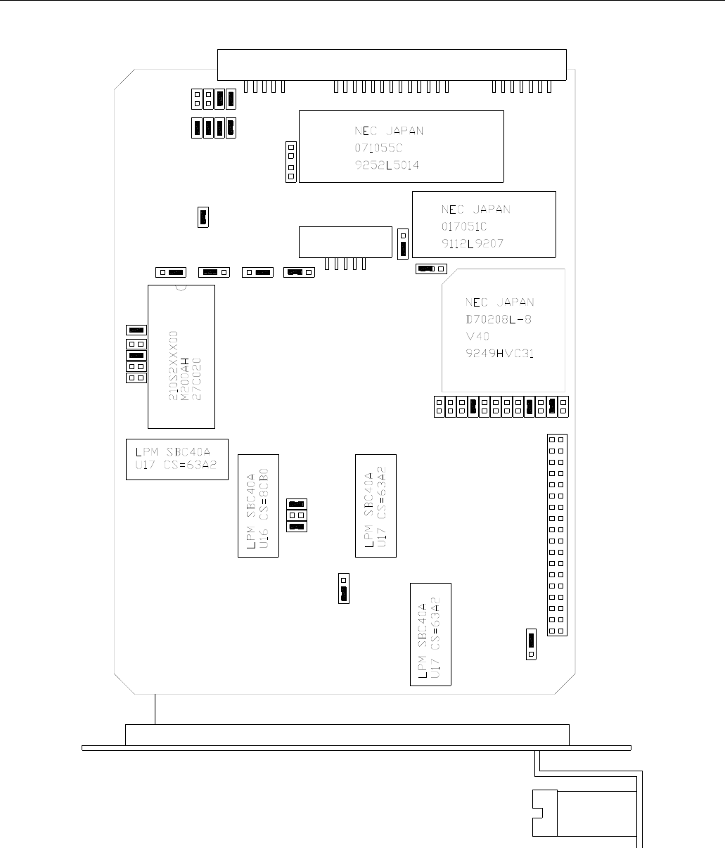
Teledyne API Model 200AH NOX Analyzer Instruction Manual, 06492, Rev. G2
9-33
Figure 9-2: CPU Board Jumper Settings

Teledyne API Model 200AH NOX Analyzer Instruction Manual, 06492, Rev. G2
9-34
9.3.1.3. Front Panel Keyboard
The keyboard consists of 8 keys and 3 LED's. Key strokes are sent to the SBC40 computers'
parallel port. The computer software detects the key strokes via CPU interrupts. The bottom line
of the display consists of 40 characters which is divided into 8 - 5 character fields. Each field
defines the function of the key immediately below it. The definition of the keys is variable and
depends on the menu level of the software.
To check the operation of the keyboard, each key should perform an operation indicated by its
current definition shown on the second line of the display.
Example #1 - testing key#1 (left most key).
At the top level menu key #1 is defined as the TEST function. Pressing this key should cause the
middle field of the top line of the display to show the various test functions.
Example #2 - testing key #8 (right most key). At the top level menu Key #8 is defined as the
SETUP key. Pressing key #8 should cause the SETUP menu to be displayed.
Example #3 - If the 5 character field above any key is blank, the key is not defined, pressing the
key has no effect.
The 3 status LED's indicate several functional states of the instrument such as calibration, fault,
and sample modes. The state of the LED's is controlled by 3 lines on the parallel port of the
SBC40. Functioning of the LED's can be checked by:
1. Turn off the M200AH power.
2. While watching the LED's, turn on the instrument power.
3. When the power comes up, the computer momentarily applies power to all 3 LED's for
approximately 1 sec. If all the LED's are observed to light, they are working properly.
9.3.2. RS-232 Communications
The M200AH uses the RS-232 communications protocol to allow the instrument to be connected
to a variety of computer based equipment. RS-232 has been used for many years and is well
documented. Generally, The M200AH uses the RS-232 communications protocol to allow the
instrument to be connected to a variety every manufacturer observes the signal and timing
requirements of the protocol very carefully. Problems arise when trying to specify connectors,
and wiring diagrams that attach the analyzer to various devices.
Teledyne API Model 200AH NOX Analyzer Instruction Manual, 06492, Rev. G2
9-35
Figure 9-3: RS-232 Pin Assignments

Teledyne API Model 200AH NOX Analyzer Instruction Manual, 06492, Rev. G2
9-36
9.3.2.1. RS-232 Port
If the RS-232 port is not working, check the following:
Physical Wiring
Refer to Figure 9-3 for the wiring diagram of the DB-9 plug on the M200A rear panel. There are
two features that make connecting the wiring easier. First is the red/green LED’s on the rear
panel. One device (such as the M200AH) provides the power to run the red LED, the other
device will provide the power for the green LED. If the wiring is hooked up correctly both
LED’s will be illuminated. There is a DTE-DCE switch, this switch interchanges pin 2 & 3 on
the
DB-9 connector. Set the DTE-DCE switch so that both LED’s are illuminated.
RS-232 Protocol (BAUD rate, Data bits, Parity)
The communication protocol for each instrument must match. In Figure 9-3 the default RS-232
parameters are listed. The BAUD rate can be changed in the software menus under SETUP-
MORE-COMM-BAUD.
Data Communications Software for a PC
You will need to purchase a software package so your computer can transmit and receive on its
serial port. There are many such programs, we use PROCOMM at Teledyne API. Once you set
up the variables in PROCOMM and your wiring connections are correct, you will be able to
communicate with the analyzer.
If connecting to a modem, check the following:
Modems are especially difficult because they may have pins that need to be at certain EIA RS-
232 levels before the modem will transmit data. The most common requirement is the Ready to
Send (RTS) signal must be at logic high (+5 V to +15 V) before the modem will transmit. The
Teledyne API analyzer sets pin 8 (RTS) to 10 volts to enable modem transmission.
To troubleshoot a modem connection first disconnect the RS-232 cable from the Analyzer and
verify (use a DVM) that you are getting a signal on Pin 2 of the RS232 port on the Analyzer. The
signal will be between -5V and -15V with respect to signal ground (pin 5). If not, there is a
problem with the CPU board or the cable. This is the transmit (TD) signal out of the Analyzer.
This should then be connected to TD input on the modem, normally Pin 2. You may need to
change the DTE/DCE switch on the M200AH so the signal is on Pin 2 of the modem.
Go to the cable connected to the modem/terminal and verify (use a DVM) that you are getting a -
5 V to -15 V signal on Pin 3 of the cable. This pin should be connected to Pin 3 of the Teledyne
API Analyzer.

Teledyne API Model 200AH NOX Analyzer Instruction Manual, 06492, Rev. G2
9-37
Check that the voltage level on Pin 8 of the Analyzer is between +5 V and +15 V. This pin
should be connected (through the cable) to Pin 4 of the modem.
Now set the baud rate of the Analyzer to the speed required by the modem and it should work. If
you are still experiencing problems, a cable adapter may be needed. Please contact the factory
for assistance.
9.3.3. Voltage/Frequency (V/F) Board
The V/F Board consists of 16 analog input channels, each software addressable, 8 digital inputs,
and 24 digital outputs, each independently addressable, and 4 independent analog output
channels. The analog input channels are connected to a V/F converter capable of 80,000 counts,
which is approximately 16 bit resolution. The integration period is software selectable from
40 msec to 2.4 secs. Commands from the SBC40 computer and digitized values from the V/F
section of the board are sent via the STD bus interface. The schematic for the board is in the
Appendix.
The overall operation of this board is quite complex, to fully check it out in all of its operational
modes is not possible in the field. Therefore a few of simple tests are described here that test one
analog input channel, the 4 analog output channels, one digital input, and one digital output.
1. V/F board analog input test.
Each analog channel is routed through a programmable 16 channel multiplexer. Chances are
that if one channel works, they all work.
A. Turn on instrument.
B. Press TEST key on front panel keyboard until DCPS test is displayed.
C. The value displayed should read 2500 200 mV.
If the M200AH passes this test, it has successfully digitized a 2500 mV composite voltage
output from the Power Supply Module. The signal should also be quiet 25 mV.
2. Analog output channel test.
In the DIAGNOSTIC menu on the front panel, there is a test that outputs a step voltage to the
4 analog outputs. This test is useful for calibrating chart recorders and dataloggers attached
to the M200AH. The test can also be useful in diagnosing faults in the V/F board.

Teledyne API Model 200AH NOX Analyzer Instruction Manual, 06492, Rev. G2
9-38
A. Turn on the instrument.
B. Enter the SETUP-MORE-DIAG menu.
C. Select the ANALOG OUTPUT test. This causes the M200AH to output a 5 step voltage
pattern to the 4 analog outputs on the rear panel. The status of the test is shown on the
front panel display. The scrolling can be stopped at any voltage by pressing the key below
the changing percentage display. The values are 0-20-40-60-80-100% of whatever voltage
range has been selected. For example the voltages would be 0, 1, 2, 3, 4, 5 V if the 5 V
range had been selected.
D. Use a DVM on each of the analog output channels to confirm the correct voltages.
If the voltages step, but are the wrong values, the V/F board may be out of calibration.
3. Digital input channel test.
The digital I/O section of the V/F board has 8 input bits and 24 output bits. Two of the
8 input bits are assign as calibration controls. See Section 7.5 for information calibration
using external contact closures.
To test the digital inputs:
A. Turn on the M200AH.
B. Connect a jumper wire across pins 1 and 2 of the “REMOTE IN” rear panel connector as
shown in Figure 2-2.
C. Shortly after closure is made the instrument should switch into zero mode as indicated on
the front panel display.
D. Remove the jumper. Shortly after the jumper is removed the instrument should exit the
zero calibrate mode.
4. Digital output channel test.
There are 24 output bits on the V/F board. The 24 bits are made up of 3 - 8 bit ports. It is
possible for a single 8 bit port or even a single bit within a port to fail.
A quick observational test of the digital outputs is to observe the LED's in the Power Supply
Module (Refer to Figure 9-5 for the location of the LED's in the PSM). The state of the
LED's can be checked from the Table 9-10. The comment section assumes the M200AH has
been running for at least 45 minutes.
A more detailed test is in the DIAGNOSTIC menu. See Diagnostic tests in Section 9.1.3.

Teledyne API Model 200AH NOX Analyzer Instruction Manual, 06492, Rev. G2
9-39
9.3.3.1. ADC/DAC Calibration Procedure
Due to the stability of modern electronics, this procedure should only need to be performed if a
major sub-assembly is exchanged or when the display voltage does not match the input voltage
or current to the V/F card. After completion, a Factory Calibration Procedure should be
performed, see Section 9.1.6.
Before the actual calibration is performed, switches on the V/F card must be correctly set and
jumpers set on the motherboard. Jumper and switch setting changes must be performed with
the instrument power OFF.
Motherboard Jumpers
The motherboard contains 4 pairs of jumpers JP1 - JP8, one pair for each analog output channel.
Each channel can be configured for either voltage or current output. Use Table 9-7 to configure
the jumpers.
Table 9-7: Motherboard Jumper Settings
Analog Output Terminal Pair
Rear panel Jumper Pair Jumper Setting for
Voltage Mode Jumper Setting for
Current Mode
DAC 0 - NOX 3 - 4 JP3 - JP4 B - C A - B
DAC 1 - NO 5 - 6 JP1 - JP2 B - C A - B
DAC 2 - NO2
(units w/o O2) 1 - 2 JP5 - JP6 B - C A - B
DAC 2 - O2
(units with O2) 1 - 2 JP5 - JP6 B - C A - B
DAC 3 - TEST 7 - 8 JP7 - JP8 B - C A - B
V/F Board Switch Settings
There are 2 different types of current outputs, Non-Isolated (std equipment) and Isolated. Each
requires a different switch setting shown below. If you are operating the instrument in voltage
output mode, the switches should be set to the desired voltage range.
Table 9-8: V/F Board Switch Settings
DAC # Sw 1 Sw 2 Sw 3 Sw 4 Sw 5 Sw 6 Sw 7
0 ON* OFF* OFF*
1 ON* OFF* OFF*
2 ON* OFF* OFF*
3 ON* OFF* OFF*
*Required settings
Teledyne API Model 200AH NOX Analyzer Instruction Manual, 06492, Rev. G2
9-40
10 V output or non-isolated current loop
Switch State Comment
3 ON Use for non-isolated current loop or 10 V output
4 OFF Use for non-isolated current loop or 10 V output
5 OFF Use for non-isolated current loop or 10 V output
6 OFF Use for non-isolated current loop or 10 V output
5 V output or isolated current loop
Switch State Comment
3 OFF Use for isolated current loop or 5 V output
4 ON Use for isolated current loop or 5 V output
5 OFF Use for isolated current loop or 5 V output
6 OFF Use for isolated current loop or 5 V output
1 V output
Switch State Comment
3 OFF Use for 1 V output
4 OFF Use for 1 V output
5 ON Use for 1 V output
6 OFF Use for 1 V output
100 mV output
Switch State Comment
3 OFF Use for 100 mV output
4 OFF Use for 100 mV output
5 OFF Use for 100 mV output
6 ON Use for 100 mV output
1. After the switches and jumpers are set, turn on instrument power and complete the following:
A. Press SETUP-MORE-DIAG, then press ENTR. Scroll to D/A CALIBRATION, press
ENTR. Press A/D to select the first task, which is to calibrate the A/D converter.
B. Connect a DVM ground lead to TP3-AGND on the V/F board. Connect the positive lead
to TP9-DAC0.

Teledyne API Model 200AH NOX Analyzer Instruction Manual, 06492, Rev. G2
9-41
C. The M200AH will display a voltage near 1% of the voltage range set in the above
procedure. Adjust R27 until the displayed voltage matches the DVM voltage, then press
ENTR.
D. The M200AH will display a voltage near 90% of the voltage range set in the above
procedure. Adjust R31 until the displayed voltage matches the DVM voltage, then press
ENTR. This step calibrates the instrument A/D converter to the external DVM.
The next task is to calibrate each of the 4 DAC output channels. The NEXT - PREV buttons
allows selection of any of the 4 D/A channels. DAC0 - the NOX channel - is displayed first.
E. The SET button has 2 functions, first to select the output mode - voltage or current. Press
VOLT and CURR depending on the type of output desired. - Remember, the VOLT or
CURR setting must match the switch and jumper settings made previously. Second,
the voltage output can be biased up to 10% of the selected range with the OFFSET
parameter. Just key in the desired offset, or press EXIT to leave the OFFSET at zero.
F. For DAC channels in VOLTAGE mode, press CAL. This will cause the instrument to
automatically calibrate the channel.
G. For DAC channels in current mode, first connect a 250 ohm resistor in series with a
current meter to the correct pair of terminals on the rear panel, see Table 9-6 for terminal
assignments. Press CAL. The instrument will output 4 mA to the rear panel terminals. UP,
DOWN and ENTR buttons will be displayed. Press the UP - DOWN buttons until the
correct reading is displayed on the meter, then press ENTR. 20 mA is then output to the
rear panel. As before, press the UP, DOWN buttons to get the correct reading, then press
ENTR.
H. To go the next channel press the NEXT button and follow the previous steps starting with
step - f. Proceed through all 4 DAC channels, then exit. To back up to previously
calibrated channels, press the PREV button.
9.3.3.2. Changing Output Voltage Ranges
Several different output voltage ranges can be selected by switch settings on the V/F board. See
Figure 9-4. If you change the analog output voltage range, the power to the instrument should be
turned off, then on and a DAC calibration performed (Section 9.3.3.1).
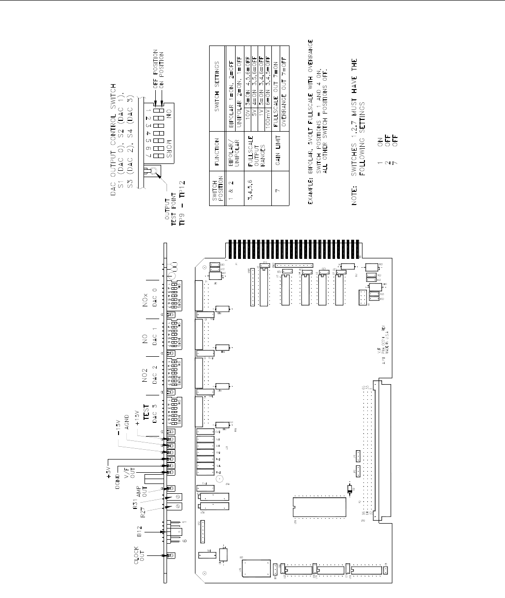
Teledyne API Model 200AH NOX Analyzer Instruction Manual, 06492, Rev. G2
9-42
Figure 9-4: V/F Board Jumper Settings

Teledyne API Model 200AH NOX Analyzer Instruction Manual, 06492, Rev. G2
9-43
9.3.4. Status/Temp Board
The Status/Temp Board is a multifunction board that:
1. Converts the resistance readings of the thermistors to a voltage.
2. Amplifies and scales the thermocouple voltage for the V/F card.
3. Provides status output circuitry.
4. Provides circuitry for contact closure inputs.
5. Provides circuitry for display brown-out/reset at low line voltage.
6. Provides circuitry for 4-20 mA outputs.
9.3.4.1. Temperature Amplifier Section
The 4 thermistor amplifiers that convert resistance into voltage monitor:
1. Reaction Cell temperature.
2. Heated Orifice block.
3. Box temperature.
4. Spare.
The voltages of the thermistor and thermocouple amplifier outputs are brought out to test points
on the edge of the board. Refer to the schematic in the Appendix for details. The voltages can
also be read using the DIAGNOSTIC - SIGNAL I/O feature. See Table 9-4 for details.
Thermistor Temperature Amplifier Adjustments
The 4 temperature amplifiers are controlled by a common pot (R34) on the upper edge of the
card.
If the temperature readouts are in error:
1. Locate the Box temp thermistor on the board and place a thermometer near the thermistor.
2. Select the BOX TEMP - TEST function on the front panel.
3. Adjust R34 until the front panel readout matches the thermometer readout. This will cause all
of the readouts to accurately measure their respective temperatures.
Converter Thermocouple Amplifier Adjustments.
The converter temperature is sensed by a Type K thermocouple. The cold junction compensation
and signal conditioning are done on the Temp/Status board.

Teledyne API Model 200AH NOX Analyzer Instruction Manual, 06492, Rev. G2
9-44
The thermocouple amplifier for the converter temperature has a gain adjustment. The voltage
across J2 reads 27.5 mV when the converter temperature is 700°C. The CPU is programmed to
always drive the temp to 700°C, so the thermocouple voltage must be used as the absolute
reference as to the correct temperature.
The temperature can be adjusted by the R6 pot. To adjust the converter temperature:
1. Select the CONV TEMP - TEST function on the front panel.
2. Wait until the converter is up to temperature, usually 30-45 min after a cold start.
3. Adjust R6 until the front panel readout equals 700C for the CONV TEMP and the voltage at
J2 is 27.5 mV.
4. Recheck the two readings 15 min later and re-adjust if necessary.
9.3.4.2. Display Brownout
During low AC line conditions the display can lock up due to insufficient voltage. When low
line conditions are approaching, this circuit senses the condition by monitoring the un-regulated
+5 VDC in the Power Supply Module. If brownout conditions are met, the DISP_BROWNOUT
line is asserted and the CPU sends a hardware RESET command to the display and sends a
BRNOUT RESET pulse back to U4. Brownout conditions will be noticed by the display flashing
every 8 seconds.
9.3.4.3. Status Output Lines, External Contact Closures
The Status lines consist of 4 active input lines, and 12 active output lines. Individual lines are set
or cleared under CPU control depending on the assigned alarm condition. The CPU also
monitors the 4 input lines for remote calibration and range control commands. The status inputs
and outputs are terminated at the rear panel, see the schematic in the Appendix.
The output lines are opto-coupled NPN transistors which can pass 50ma max of direct current
with a voltage of 30 VDC max.
The input lines are optically coupled with inputs pulled up to +5 VDC. External contacts can be
contact closures or open collector transistor contacts. DO NOT apply any voltage, since +5 VDC
is supplied internally.
Individual status lines can be set or cleared using the DIAGNOSTIC mode SIGNAL I/O. This
can be useful for simulating fault conditions in the analyzer to see if external circuitry is working
correctly. See Table 5-8 for pin assignments.

Teledyne API Model 200AH NOX Analyzer Instruction Manual, 06492, Rev. G2
9-45
9.3.4.4. 4-20 mA Current Output
There are two types of current loop outputs available for the M200AH, non-isolated (standard
equipment) and isolated (optional). These outputs may be used in place of the analog voltage
signals that appear at the rear panel connector. See Section 9.3.3.1 for setup and calibration
procedure.
Non-isolated 4-20 mA or 0-20 mA Output
Non-isolated 4-20 mA is recommended for applications requiring a current loop and the current
loop receiver has an isolated input stage. It can also be used when there a potential difference
does not exist between the ground connections of the two instruments.
Recommended load (Rl) = 100 - 600 (Max. 600)
V/F analog output voltage setting = +10 V Full Scale
Default Setting = 4-20 mA
To convert from 4-20 mA to 0-20 mA output, refer to Status/Temp Schematic 01087 sheet 2, and
the procedure in Section 9.3.3.1.
Isolated 4-20 mA or 0-20 mA Option
This option is recommended where maximum isolation from ground loops is required.
Specifications include up to 1500 V rms common mode voltage isolation (transformer coupled
input to output galvanic isolation) and 240 Vrms normal mode voltage output protection.
Recommended load (Rl) = 200 - 1000 (Max. 1200)
V/F analog output voltage setting = +5V Full Scale
Default Setting = 4-20 mA
To convert from 4-20 mA to 0-20 mA output, refer to Status/Temp Schematic in the Appendix,
and the procedure in Section 9.3.3.1.
9.3.5. Power Supply Module
The Power Supply Module consists of several subassemblies described in Table 9-10.

Teledyne API Model 200AH NOX Analyzer Instruction Manual, 06492, Rev. G2
9-46
Table 9-9: Power Supply Module Subassemblies
Module Description
Linear Power Supply
Board The linear power supply board takes multiple voltage inputs from the power
transformer and produces +5, +15, -15, +12 VDC outputs. The outputs are
routed to two external connectors, P2 and P3. See Figure 9-5. The +5 is used
for operating the CPU. The 15 is used in several locations for running op-
amps and IC's. The +12 is used for operating fans and valves.
Switching Power
Supply The switching power supply supplies +15 VDC at 4 A to the PMT cooler
control on the Sensor Module and input power for the ozone generator. The
output is made available through J10 on the Switch Board. There is a load
resistor on the Switch Board to keep the output stable when little current is
required from the supply.
Switch Board The Switch Board has many different functions. It takes logic signals from
the V/F board and uses them to switch 4-115 VAC and 4-12 VDC loads.
The board also contains the instrument central grounding tie point. It routes
unswitched AC and DC power as needed. Connector P2 programs the power
transformers to take 115, 220, 230 or 240 VAC inputs.
Power Transformers There are potentially 2 input power transformers in the PSM. The multitap
transformer T1 is in every M200AH and supplies input power for the Linear
Power Supply board described above. A second transformer T2 is added if
220, 230 or 240 VAC input is required. This transformer steps down the
220/230/240 VAC to 115 VAC/50Hz for heaters and other components.
Input power selection is done via a programming connector P2 which
provides the proper connections for either foreign or domestic power.
Circuit
Breaker/Power
Switch
The front panel contains a combination circuit breaker - input power switch.
It is connected to the PSM through J6 on the Switch Board. If an overload is
detected the switch goes to the OFF position. Switching the power back on
resets the breaker also.
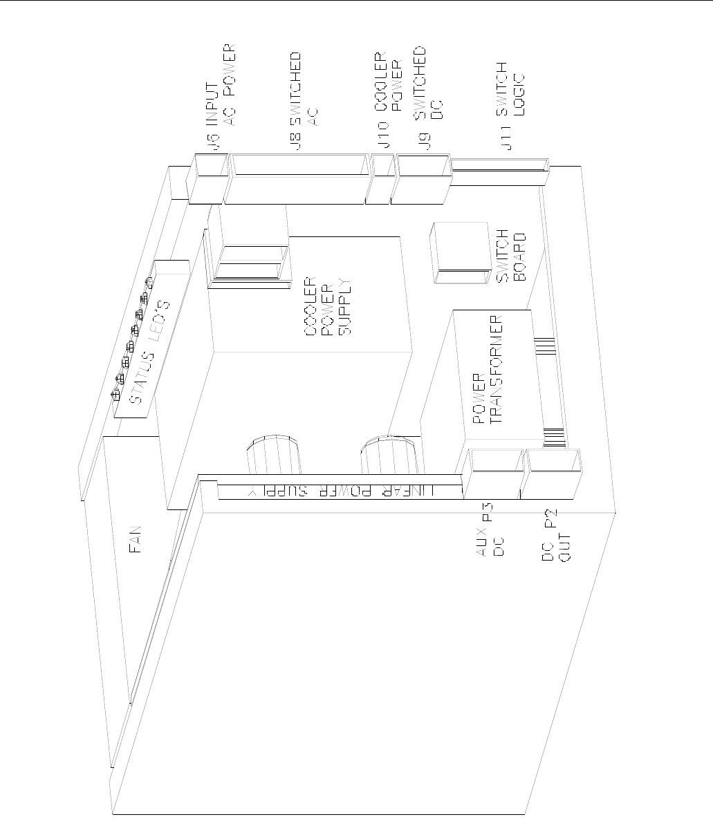
Teledyne API Model 200AH NOX Analyzer Instruction Manual, 06492, Rev. G2
9-47
Figure 9-5: Power Supply Module Layout
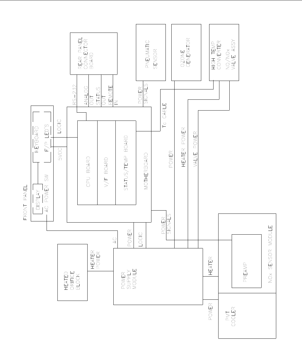
Teledyne API Model 200AH NOX Analyzer Instruction Manual, 06492, Rev. G2
9-48
Figure 9-6: Electrical Block Diagram

Teledyne API Model 200AH NOX Analyzer Instruction Manual, 06492, Rev. G2
9-49
PSM Diagnostic procedures:
The Linear Power Supply board can be tested by checking the DCPS - TEST function on the
front panel. It should read 2500 mV 200 mV. If the value is outside this range, individual
output voltages can be tested on connector P3, see the schematic in the Appendix for pinouts.
The Switching Power Supply output can be tested by observing the red LED on the TEC control
board attached to the inside of the fan duct on the Sensor Module. If the LED is on, +15 VDC is
being supplied to the cooler. The current draw through the cooler can be measured across TP1
and TP2. The value of the current in amps is 10x the voltage measured, and is typically 1.5 to 2.0
amps at room temperature.
The Switch Board can be tested by observing the diagnostic LEDS along the top edge of the
board. The following Table 9-10 describes the typical operation of each LED.
Table 9-10: Power Supply Module LED Operation
No. Function Description
1. NO/NOx Valve Should switch about every 6 sec. On = NOx mode Off = NO mode.
2. AutoZero Valve Should switch every 2 minutes. On = Azero Off = Sample mode.
3. Ozone Generator
Power Power to ozone generator is off for 30 minutes after turning on an
instrument that has been off for a long time.
If the instrument has been turned off for less than 60 minutes, the
ozone generator is immediately turned on.
4. Block Heater Should cycle ON-OFF every 20 sec to 2 min. On continuously until
up to temp.
5. Conv Heater Should cycle ON-OFF every 20 sec to 2 min. On continuously until
up to temp.
6. Reaction Cell Heater Should cycle ON-OFF every 20 sec to 2 min. On continuously until
up to temp.
9.3.6. Ozone Generator
The ozone generator subsystem consists of a permeation drier, flowmeter, transformer -
generator assembly, and driver board. The location of the components is illustrated in Figure 9-7.
Ozone is generated by drying ambient air, then passing the air between two electrodes that have
a large oscillating electric field generated by a high voltage transformer.
The generator cartridge - transformer assembly is potted to eliminate corona and increase safety.
The module cannot be disassembled.
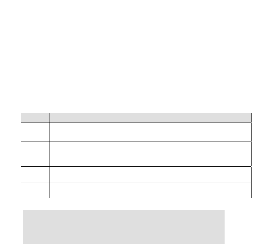
Teledyne API Model 200AH NOX Analyzer Instruction Manual, 06492, Rev. G2
9-50
Common faults in the ozone generator are:
1. A leak or some other failure in the drier will let ambient air into the generator. There is
enough water vapor in room air to cause the generator to make nitric acid aerosol. It is very
corrosive and causes the generator cartridge to short out, and plug up due to salt build-up.
This reduces the ozone concentration generated, which can cause the analyzer to be non-
linear due to insufficient ozone concentration. Also, the nitric acid can destroy parts down
stream of the generator.
2. Contaminated ozone generator cartridge. Disconnect fittings and run water through the
cartridge to clean.
3. Failure of the driver board.
Table 9-11: Ozone Generator Control Conditions
Condition Description Ozone Generator
1 Manual override off (SETUP-MORE-DIAG-OZONE GEN). OFF
2 Manual override on. ON
3 Ozone flow below low warning limit for 5 minutes
(OFLOW_SET setup variable). OFF
4 Instrument powered on for more than 30 minutes. ON
5 Instrument powered off for less than 1 hour and ozone
generator was on when instrument was powered off. ON
6 Ozone flow above low warning limit for 0.5 minutes and
condition 4 or 5 is true. ON
NOTE
The ozone generator is independently controlled in the SIGNAL I/O, OPTIC
TEST, and ELECTRICAL TEST diagnostics. After exiting these diagnostics,
the ozone generator is restored to the state specified by the above conditions.

Teledyne API Model 200AH NOX Analyzer Instruction Manual, 06492, Rev. G2
9-51
9.3.6.1. The PermaPure Drier
The PermaPure drier is constructed of 2 concentric tubes. The inner tube is a special material
that has an affinity for water vapor. The outer annulus is evacuated by the instrument pump. This
creates a concentration gradient causing water in ambient air to diffuse into the outer annulus,
thus the air in the inner tube becomes progressively drier as it progresses down the tube.
Due to the large number of connections and fittings on the drier, the most common drier fault is
leaks. Before proceeding with any other procedures check the drier for leaks.
Occasionally the drier gets contaminated. The manufacturer of the drier recommends replacing
the drier rather than trying to clean it. If cleaning is chosen, the following options are available:
1. Dirt - Clean any solids from dryer inlet by brushing. Use clean dry air to blow any loose
particles from the inlet. De-ionized water or dilute (5-10% conc HCl in de-ionized water)
hydrochloric acid can be passed thru the dryer. This should be done only with the dryer and
HCl at room temperature.
2. Contamination with organic liquids and Freons - rinse the inner and outer tubes using 1,1,1
trichlorethane. Follow the solvent with dry air to purge the solvent.
3. Inorganic salts and oxgenated hydrocarbons can be removed by rinsing with 10% nitric acid
at 50C.
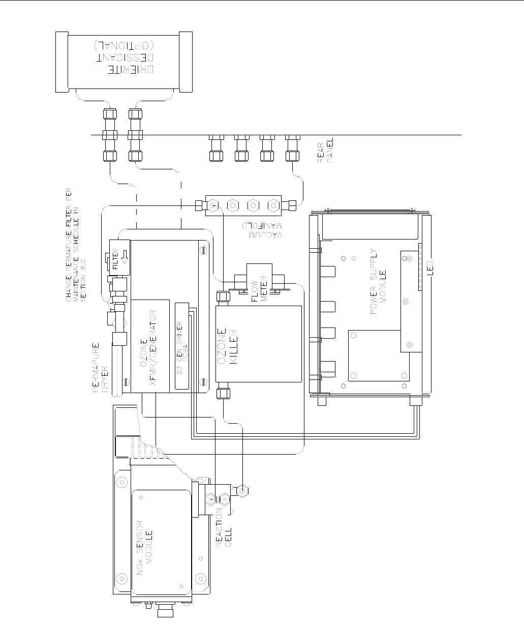
Teledyne API Model 200AH NOX Analyzer Instruction Manual, 06492, Rev. G2
9-52
Figure 9-7: Ozone Generator Subsystem

Teledyne API Model 200AH NOX Analyzer Instruction Manual, 06492, Rev. G2
9-53
9.3.7. Flow/Pressure Sensor
The flow/pressure sensor board consists of 2 pressure sensors and a flow sensor. See Figure 9-8
for a diagram of this board. From these three sensors four values are computed and displayed on
the front panel TEST functions. They are:
1. Ozone Flow - measured directly - S3, R3
2. Reaction Cell Pressure - measured directly - S2, R2
3. Sample Gas Pressure - measured directly S1, R1
4. Sample Flow - computed from sample pressure and reaction cell pressure S1, S2
The above pressures and flows are filtered to produce the front panel readings. There is a small
delay after adjustment for a steady reading when observing the TEST functions.
To adjust the OZONE flow:
1. Go to DIAG mode by pressing SETUP-MORE-DIAG, then select SIGNAL I/O, and press
ENTR. Select OZONE_FLOW by using NEXT-PREV keys.
2. Adjust R3 so that OZONE_FLOW reads 2000 mV. This is the coarse adjustment.
3. Press EXIT to return to the SAMPLE mode. Select the OZONE FL - TEST function. Plumb
a calibrated flow measuring device upstream of the ozone generator (see Figure 9-7). Use the
external device reading to make small adjustments in R3 to dial in correct flow readout on
the front panel.

Teledyne API Model 200AH NOX Analyzer Instruction Manual, 06492, Rev. G2
9-54
To adjust the SAMPLE PRESSURE:
1. Go to DIAG mode by pressing SETUP-MORE-DIAG, then select SIGNAL I/O, and press
ENTR. Select SAMPLE_PRESS by using NEXT-PREV keys.
2. Adjust R1 to read 4100 mV. This is the coarse adjustment.
3. Press EXIT to return to the SAMPLE mode. Select SAMP - TEST function. Use a calibrated
absolute pressure meter to make small adjustments to R1 until the correct absolute pressure is
displayed. 29.92 in-Hg-A is the target value at sea level. The rate of decrease is about 1"-Hg
per 1000 ft of altitude.
To adjust the REACTION CELL PRESSURE:
1. Go to DIAG mode by pressing SETUP-MORE-DIAG, then select SIGNAL I/O, and press
ENTR. Select RCELL_PRESS by using the NEXT-PREV keys.
2. Disconnect the vacuum pump at the Sample Exhaust port on the instrument rear panel.
3. Press EXIT to return to the SAMPLE mode. Select RCEL - TEST function. Use a calibrated
absolute pressure meter to make small adjustments to R1 until the correct absolute pressure is
displayed. 29.92 in-Hg-A is the target value at sea level. The rate of decrease is about 1"-Hg
per 1000 ft of altitude.
4. Re-connect the sample pump. The RCELL reading should now display the reaction cell
absolute pressure of approximately 5 in-Hg-A.
To adjust the SAMPLE FLOW:
1. In SAMPLE mode, scroll the TEST functions to SAMP FLW. Observe the reading. Then
subtract the observed reading from the desired reading.
2. Go to the VARS menu by SETUP-MORE-VARS, then pressing ENTR. Scroll to
SFLOW_SET and press EDIT. The first value displayed is the SFLOW_SET:VALUE
reading, ADD the value from step 1 to the reading shown and key in the new reading, then
press ENTR. Check the low and high warning limits, which are displayed as the next 2
values to make sure the new value does not exceed the warning limits. Press exit to return to
SAMPLE mode.
3. Observe the SAMP FLW value. If necessary repeat step 2 to adjust the reading again to
match the desired flow rate.
Teledyne API Model 200AH NOX Analyzer Instruction Manual, 06492, Rev. G2
9-55
Figure 9-8: Flow/Pressure Sensor
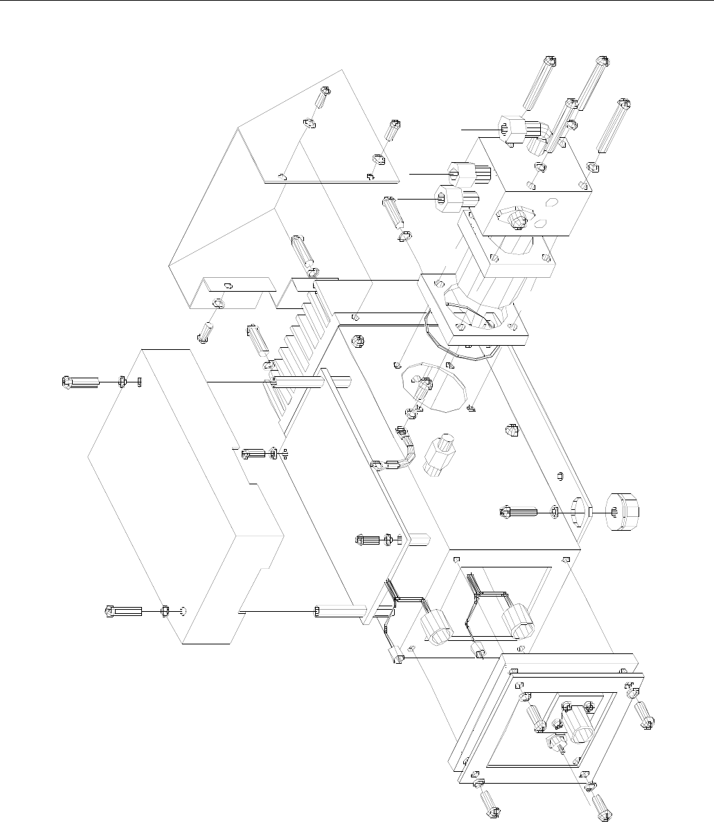
Teledyne API Model 200AH NOX Analyzer Instruction Manual, 06492, Rev. G2
9-56
Figure 9-9: NOX Sensor Module
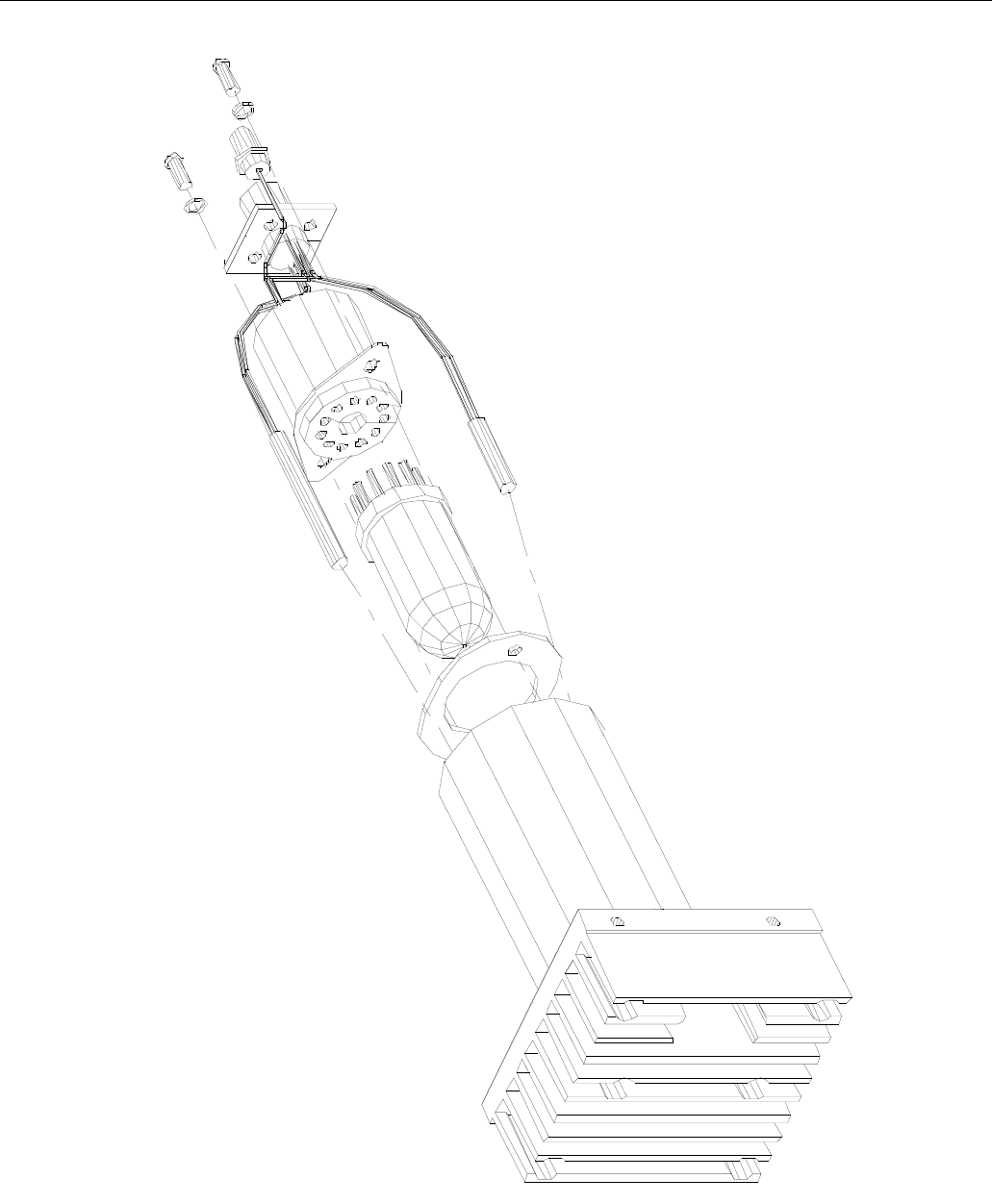
Teledyne API Model 200AH NOX Analyzer Instruction Manual, 06492, Rev. G2
9-57
Figure 9-10: NOX Sensor Module

Teledyne API Model 200AH NOX Analyzer Instruction Manual, 06492, Rev. G2
9-58
9.3.8. NOX Sensor Module
Figure 9-9 and Figure 9-10 show the assembly of the NOX sensor module.
9.3.8.1. PMT
The PMT detects the light emitted by the reaction of NO with ozone. It has a gain of about
500,000 to 1,000,000. Because of its high sensitivity to light, it is not possible to test the detector
outside of the instrument in the field. The best way to determine if the PMT is working is by
using Optic test. OT operation is described in Section 9.1.3.3.
The basic method to diagnose a PMT fault is to eliminate the other components using ET, OT
and specific tests for other sub-assemblies.
9.3.8.2. Reaction Cell Temperature
The reaction cell temperature is controlled by the CPU. It operates by reading a thermistor
amplifier on the Status/Temp board. The CPU controls the temperature by toggling a bit on the
V/F board. The V/F board TTL logic controls a solid state switch on the Switch Board in the
PSM. The switched 115 VAC comes out of the PSM to a connector near the underside of the
reaction cell. A warning message may be present during initial warm-up due to the temperature
being below the 50C setpoint.
9.3.8.3. Preamp Board
The NOx Preamp Board is a multifunction board providing circuitry to support the following
functions.
1. Preamp, buffer amplifier, physical range control hardware for the PMT detector.
2. Precision voltage reference and voltage generation, and control for the PMT - HVPS inside
the sensor module.
3. Constant current generator and adjustment for the Optic Test LED.
4. Voltage generation and adjustment for Electric Test.
5. Thermistor amplifier, control signal generation for the PMT cooler.
The setup and adjustment of items 1-4 above is covered in the Factory Calibration procedure in
Section 9.1.6. Item 5 has no adjustable features.

Teledyne API Model 200AH NOX Analyzer Instruction Manual, 06492, Rev. G2
9-59
9.3.8.4. PMT Cooler
The PMT cooler uses a Peltier cooler supplied with DC current from the switching power supply
in the Power Supply Module. An overall view is shown in Figure 9-11. The temperature is
controlled by a proportional temperature controller located on the Preamp board. The input
voltage from the supply is 15 VDC. Typical current through the cooler at room temp is about 1.5
to 2 A. At normal room temperatures the 7C set point should be maintained within 0.1C. The
current and voltage can be measured at test points on the fan shroud at one end of the NOX
sensor module. See the Schematic in the Appendix.
Teledyne API Model 200AH NOX Analyzer Instruction Manual, 06492, Rev. G2
9-60
Figure 9-11: PMT Cooler Subsystem

Teledyne API Model 200AH NOX Analyzer Instruction Manual, 06492, Rev. G2
9-61
9.3.8.5. High Voltage P.S.
The HVPS is located in the interior of the Sensor Module, and is plugged into the PMT tube. It
requires 2 voltage inputs. The first is +15 VDC, which powers the supply. The second is the
programming voltage, which is generated on the Preamp Board. This power supply is unlike a
traditional PMT HVPS. It is like having 10 independent power supplies, one to each pin of the
PMT. The test procedure below allows you to test each supply.
Adjustment of the HVPS is covered in the Factory Calibration Procedure in Section 9.1.6.
To troubleshoot the HVPS:
1. Turn off the instrument.
2. Remove the cover and disconnect the 2 connectors at the front of the NOx Sensor Module.
3. Remove the end cap from the sensor.
4. Remove the HVPS/PMT assembly from the cold block inside the sensor. Un-plug the PMT
tube.
5. Re-connect the 7 pin connector to the Sensor end cap, and power-up the instrument.
6. Use Figure 9-12 to check the voltages at each pin of the supply.
7. Turn off the instrument power, and re-connect the PMT tube, then re-assemble the sensor.
If any faults are found in the test, you must obtain a new HVPS as there are no user serviceable
parts inside the supply.
Teledyne API Model 200AH NOX Analyzer Instruction Manual, 06492, Rev. G2
9-62
Figure 9-12: High Voltage Power Supply

Teledyne API Model 200AH NOX Analyzer Instruction Manual, 06492, Rev. G2
9-63
9.3.9. Z/S Valves
The Z/S Valves is an option in the instrument. Before troubleshooting this sub-assembly, check
that the options were ordered, and that they are enabled in the software. Section 7.2 shows how
the Z/S valve option should be set-up.
Check for the Z/S valves.
Check for the physical presence of the valves. See
1. Figure 2-6 for Z/S Valve location.
2. Check that the option has been enabled in the software. The front panel display, when the
instrument is in SAMPLE mode, should display CALS and CALZ buttons on the second line
of the display. The presence of the buttons indicates that the option has been enabled in
software. If the valves are present but CALS/CALZ is not displayed, call the factory.
Troubleshooting the Z/S valves.
1. Turn the instrument and sample pump on. Locate the valve module on the rear panel.
2. There is a red LED associated with each of the 4 valve positions, when the LED is ON the
valve is OPEN. Each LED corresponds top-to-bottom to each valve.
3. Correct operation of each valve can be checked as follows:
A. In sample mode, the bottom sample valve is open and the LED is ON. Check flow through
the sample inlet port on the rear panel.
B. In CALZ mode, the second from the bottom zero gas valve is open and the LED is ON.
Check flow through the zero gas port on the rear panel.
C. In CALS - LOW SPAN mode, the third from the bottom span gas valve is open and the
corresponding LED is ON. Check flow through the low span gas port on the rear panel.
D. In CALS - HI SPAN mode, the top gas valve is open and the top LED is ON. Check flow
through the high span gas port on the rear panel.
If the LED’s fail to light, check the iSBX board on the CPU board and cable for 0-5 VDC logic
signals.
If the LED’s light, but the valves do not operate, check the 12 VDC cable from the power supply
module.
The valve may be operating, but may be plugged. If that is suspected, dis-assemble the manifold
and inspect for signs of plugging. While the valves can be removed from the manifold, it is NOT
recommended that the valves be dis-assembled as there are several small spring loaded parts
inside.

Teledyne API Model 200AH NOX Analyzer Instruction Manual, 06492, Rev. G2
9-64
It is also possible to manually toggle each of the valves in the DIAGNOSTIC mode. Refer to
Section 9.1.3 for information on using the DIAG mode. Also refer to Figure 8-4, Figure 8-5 for a
pneumatic diagram of the system. Check for fitting leaks and crimped tubing.
9.3.10. Pneumatic System
The pneumatic system is diagrammed in Figure 8-4, Figure 8-5, depending on which options the
instrument was ordered with.
9.3.10.1. Leak Check
CAUTION
When doing a leak check do not pressurize
the M200AH to greater than 15psi.
Damage to internal components will
occur at higher pressures.
The root cause of many performance problems is a leak. Refer to Section 8.6 for the leak check
procedure.
9.3.10.2. Pump
The external sample pump is capable of maintaining the cell pressure at 5"-Hg-A. If higher
pressures are noted, the pump may need servicing. Common pump problems and causes are:
1. Failure of ozone scrubber, thus allowing ozone into the pump. Ozone is very corrosive and
causes failure of the diaphragm. Replace catalytic ozone scrubber in the NO2-to-NO
converter, replace charcoal scrubber on pump pack, and rebuild the pump.
2. Sometimes the felt pads in the charcoal ozone scrubber plug up, thus restricting flow, and
decreasing effective vacuum even if pump is good.
3. Failed pump. The pump has a finite lifetime. There is a re-build kit, see the spare parts list.

Teledyne API Model 200AH NOX Analyzer Instruction Manual, 06492, Rev. G2
A-1
APPENDIX A
ELECTRICAL SCHEMATICS
Table A-1: Electrical Schematics
Part No. Name
00402 Sensor Board Assembly
00403 Sensor Board Schematic
00514 V/F Board Assembly
00515 V/F Board Schematic
00704 Keyboard Assembly
00705 Keyboard Schematic
0108601 Status/Temp Assembly
01087 Status/Temp Schematic
01109 Motherboard Assembly
01110 Motherboard Schematic
01114 Connector Board Assembly
01115 Connector Board Schematic
0113912 PSM Overall schematic - CE Mark
01206 Switch Board Assembly
01207 Switch Board Schematic
01464 DC Power Supply Assembly
01465 DC Power Supply Schematic
01471 4-20 mA Output Option
01668 Ozone Generator Power Supply Assembly
01669 Ozone Generator Power Supply Schematic
01839 Thermoelectric Cooler Control Assembly
01840 Thermoelectric Cooler Control Schematic
01916 Connector Board Schematic - CE MARK
01917 Connector Board Assembly - CE MARK
01930 Keyboard Assembly - CE MARK
01931 Keyboard Schematic - CE MARK
(table continued)
Teledyne API Model 200AH NOX Analyzer Instruction Manual, 06492, Rev. G2
A-2
Table A-1: Electrical Schematics (Continued)
Part No. Name
02034 A-Series Valve Driver Assembly
02035 A-Series Valve Driver Schematic
02037 ISBX I/O Port Assembly
02038 ISBX I/O Port Schematic
02107 Preamp Board Assembly
02108 Preamp Board Schematic
02222 Switch Board Assembly - CE MARK
02223 Switch Board Schematic - CE MARK
02230 DC Power Supply Assembly - CE MARK
02231 DC Power Supply Schematic - CE MARK
03172 M200A Interconnect Diagram
03173 M200AH Interconnect Diagram
03174 M200AU Interconnect Diagram
03175 M201A Interconnect Diagram
03625 Interface, 02 Sensor
04267 Schematic, M202A Motherboard
Teledyne API Model 200AH NOX Analyzer Instruction Manual, 06492, Rev. G2
B-1
APPENDIX B
SPARE PARTS AND EXPENDABLES
NOTE
Use of replacement parts other than those supplied by API may result in non-compliance with European
standard EN 61010-1.
Table B-1: Spare Parts and Expendables
Part No. Name
02047 List, Spare Parts, M200AH
01713 Level 1 Spares Kit with Mini-HiCon Converter, M200AH
0171301 Level 1 Spares Kit with Moly Converter, M200AH
01714 Expendables Kit, M200AH

Teledyne API Model 200AH NOX Analyzer Instruction Manual, 06492, Rev. G2
B-2
THIS PAGE IS INTENTIONALLY LEFT BLANK

SPARE PARTS LIST
M200AH
Part Number Description
000940100 Orifice, 3 mil, 60 cc (IZS)
000940500 Orifice, 7 mil, 250 cc (844-126010)
000940600 Orifice, 10 mil, 500 cc, Rx Cell (844-012607)
002160000 Ozone Scrubber (Charcoal)
002270100 Gasket (Rx Cell) Qty. 12
002730000 Window 665 NM (002-013100)
002760600 ASSY, CPU, 512K PROM/SW, M200AH (AMX) CE
003690000 Filter, TFE, 37 mm 5 um, Qty. 100 (872-006400)
003690100 Filter, TFE, 37 mm 5 um, Qty. 25 (872-006300)
003690200 AKIT, TFE FILTER, 37MM, 1UM (100)
003690300 AKIT, TFE FILTER, 37MM, 1UM (25)
004020200 PCA, SENSOR BD. NOX, w/FM4 & SW8
005140300 PCA, V/F CARD, W/ SCHEMATIC (B/F)
005960000 Activated Charcoal, 6 lbs.
007040000 PCA, KEYBD DISPLAY, A SERIES *
007280000 ASSY, DISPLAY (DS25) FOR "A" SERIES
009690000 AKIT, TFE FLTR ELEM, 47MM, (FL6) (100)
009690100 AKIT, TFE FLTR, 47MM, (FL6) (30)
009690200 AKIT, TFE FLTR (FL19) ELEM, 47MM, (100)
009690300 AKIT, TFE FLTR ELEMENT, 47MM, 1UM (30)
010680100 Heater, MOLY Converter
010860100 PCA, STATUS/TEMP, TYPE K, M100AH/M200AH
011310000 Drier Assembly Complete with Flow Control
011340100 ASSY, SENSOR, M200AH (WO)
011390000 ASSY, PSM,M100A/M200A, 115V/60HZ
011391200 ASSY, PSM, M200A, 115V/60HZ
011420100 ASSY, NOX CELL, M200AH (KB)
011830000 RECHARGE KIT, MOLY CHIPS (2.62OZ)
011930000 CD, PMT (R928), NOX, M200A, M200E(KB)
011980000 ASSY, THERMOCOUPLE W/ CONN, TYPE J
011980100 Assembly, MOLY Thermocouple (Type K)
012360000 ASSY, FAN, "A" PSM
013140000 Fan, PMT Cooler
013570000 Thermistor Assembly (Cooler)
013620000 Heater, MINI-HICON (OBSOLETE use P/N 037400000)
014010000 ASSY, MOLY SPARE, M200A (OBS) *
014060000 NOx PROM with Software
014080100 ASSY, HVPS, SOX/NOX
014610000 KIT, REPLACMENT COOLER ASSY, M100X/200X
014640000 PCA, DC POWER SUPPLY(OBSOLETE)
015770000 SUB-ASSY, OZONE KILLER
016200000 MANUAL, OPERATORS, M200AH
016330000 Converter, MINI-HICON without Valve
016680000 PCA, OZONE GEN DRIVER, (OBS)
017110000 Converter, Hicon Type K, w/o O3 killer, w/o valves
02047G - M200AH, SPL.xls (DCN 5333) 03/03/09

SPARE PARTS LIST
M200AH
017130000 Model 200AH Level 1 Spare Parts Kit (for 10 units) with MINI-HICON
017130100 Model 200AH Level 1 Spare Parts Kit (for 10 units) with MOLY
017140000 AKIT, EXP KIT, M200AH/EH
018080000 Desiccant Baggie Kit - Qty. 12 (DR0000002)
018300000 ASSY, SAMPLE FLOW, MANIFOLD M200AH (wo)
018350001 OZONE GENERATOR MODULE
018720000 ASSY, MOLYCON, w/O3 DESTRUCT, M200A
019300000 PCA, KEYBOARD DISPLAY (CE) OPTIONS
021070000 PCA, PREAMP, M200A, M200AH
022220000 15 Vdc, 4A Switching Power Supply
022300000 PCA, DC POWER SUPPLY, CE, (SUBASSY)
022840400 Welded Moly Conv.Long, Type K, w/o valves, w/o O3 Killer, in can
024710000 Tubing: 6’, 1/8” CLR
024720000 Tubing: 6’, 1/8” BLK
024730000 Tubing: 6’, 1/4” BLK
024740000 Tubing: 6’, 1/4” CLR
024750000 Tubing: 6’, 1/4” TYGON
037400000 Heater, MINI-HICON
039010000 Heater, MINI-HICON
059940000 OPTION, SAMPLE GAS CONDITIONER, M200A/E
060700000 ASSY, NONOX VALVE, VA24
DR0000002 PMT Desiccant Baggies (Obsolete Use P/N 018080000 )
FL0000001 Sintered Filter (002-024900)
FL0000003 Filter, DFU (036-040180)
HE0000017 Heater, Reaction Cell, 12W
HE0000019 HEATER, 65W, 120V, 6" LEADS CE APPROVED
HW0000020 Spring, Flow Control
HW0000036 TFE TAPE, 1/4" (48 FT/ROLL)
HW0000037 TIE, CABLE 6"
HW0000099 STANDOFF, #6-32X.5, HEX SS M/F
KIT000124 ASSY, CPU, 512K PROM, PROGRAMED (AMX)
OR0000001 O-Ring, Flow Control
OR0000002 O-Ring, Bearing, Cell
OR0000034 O-Ring, Fitting for RxCell
OR0000042 O-Ring, Sensor Assembly
OR0000044 O-Ring, Reaction Cell
OR0000045 O-Ring, Sample Filter
PS0000002 HIGH VOLTAGE POWER SUPPLY KB *
PU0000005 PUMP, THOMAS 607, 115V/60HZ (KB)
PU0000006 PUMP, THOMAS 607, 220V/50HZ (KB)
PU0000011 607 Pump Rebuild Kit
RL0000007 RELAY, 3 AMP OPTO (OBS)
RL0000015 Solid State Relay, 115 Vac
SW0000006 SWITCH, THERMAL, 60 C
VA0000007 Solenoid Valve, Stainless Steel, 12V
VA0000024 VALVE, NO/NOX (USE VALVE ASSEMBLY 06070)
02047G - M200AH, SPL.xls (DCN 5333) 03/03/09
LEVEL 1 SPARES KIT
(WITH MINI-HICON CONVERTER)
M200AH
Part Number Description
000940100 CD, ORIFICE, .003 GREEN
000940500 CD, ORIFICE, .007 ORANGE
000940600 CD, ORIFICE, .010 BROWN
004020200 PCA, SENSOR BD. NOX, w/FM4 & SW8
011310000 ASSY, DRYER, NOX
011930000 CD, PMT (R928), NOX, M200A, M200E(KB)
014610000 KIT, REPLACMENT COOLER ASSY, M100X/200X
016330000 ASSY, HICON W/WATLOW HTR, M200AH (KB)
016810400 ASSY, O3 GEN, M200AH, HI OUTPUT
018300000 ASSY, SAMPLE FLOW, MANIFOLD M200AH (wo)
022300000 PCA, DC POWER SUPPLY, CE, (SUBASSY)
HE0000017 HTR, 12W/120V (50W/240V), CE AP (KB)
OR0000001 ORING, 2-006VT *
PS0000002 HIGH VOLTAGE POWER SUPPLY KB *
PS0000010 PWR SUPPLY, SWITCHING, 15V, ASTEC
RL0000015 RELAY, DPDT, (KB)
VA0000024 VALVE, MANIFOLD, 3-WAY CLIPPARD
01713A - M200AH, Level 1 Spares Kit w Mini-HiCon.xls (DCN 5333) 03/03/09
LEVEL 1 SPARES KIT
(WITH MOLYBDENUM CONVERTER)
M200AH
Part Number Description
000940100 CD, ORIFICE, .003 GREEN
000940500 CD, ORIFICE, .007 ORANGE
000940600 CD, ORIFICE, .010 BROWN
00402020A PCA, SENSOR BOARD NOX, w/FM4 & SW8
01131000A ASSY, DRYER, NOX
011930000 CD, PMT (R928), NOX, M200A, M200E(KB)
014610000 KIT, REPLACMENT COOLER ASSY, M100X/200X
016810400 ASSY, O3 GEN, M200AH, HI OUTPUT
022220000 PCA, PWR SUPPLY SWITCH BD, CE (SUBASSY)
022300000 PCA, DC POWER SUPPLY, CE, (SUBASSY)
022840400 ASSY, MOLY WELDED, W/O O3 KILLER, M200AH
HE0000017 HTR, 12W/120V (50W/240V), CE AP (KB)
OR0000001 ORING, 2-006VT *
PS0000002 HIGH VOLTAGE POWER SUPPLY KB *
PU0000011 REBUILD KIT, THOMAS 607(KB)
RL0000015 RELAY, DPDT, (KB)
VA0000024 VALVE, MANIFOLD, 3-WAY CLIPPARD
0171301A - M200AH, Level 1 Spares Kit w Moly.xls (DCN 5333) 03/03/09

EXPENDABLES KIT
M200AH
Part Number Description
002270100 AKIT, GASKETS, WINDOW, (12)
009690300 AKIT, TFE FLTR ELEMENT, 47MM, 1UM (30)
FL0000001 FILTER, SS
FL0000003 FILTER, DFU (KB)
HW0000020 SPRING
OR0000001 ORING, 2-006VT *
01714A - M200AH, EXP Kit.xls (DCN 5333) 03/03/09
THIS PAGE IS INTENTIONALLY LEFT BLANK
