Teledyne 3110 Users Manual 3110_Oxygen_Analyzer_Rev 3
Teledyne Oxygen Equipment 3110 man_3110
3110 to the manual 4a58ddb1-ddb0-4020-8fc8-363fe35b4e7b
2015-02-03
: Teledyne Teledyne-3110-Users-Manual-464506 teledyne-3110-users-manual-464506 teledyne pdf
Open the PDF directly: View PDF ![]() .
.
Page Count: 52
Teledyne Analytical Instruments
OPERATING INSTRUCTIONS FOR
Model 3110
Portable Trace Oxygen Analyzer
DANGER
Toxic gases and or flammable liquids may be present in this monitoring system.
Personal protective equipment may be required when servicing this instrument.
Hazardous voltages exist on certain components internally which may persist
for a time even after the power is turned off and disconnected.
Only authorized personnel should conduct maintenance and/or servicing.
Before conducting any maintenance or servicing, consult with authorized
supervisor/manager.
Copyright © 2005 Teledyne Analytical Instruments
P/N M77970
10/16/2005
ECO:

Model 3110
ii Teledyne Analytical Instruments
All Rights Reserved. No part of this manual may be reproduced, transmitted, transcribed,
stored in a retrieval system, or translated into any other language or computer language in
whole or in part, in any form or by any means, whether it be electronic, mechanical,
magnetic, optical, manual, or otherwise, without the prior written consent of Teledyne
Instruments / Analytical Instruments, 16830 Chestnut Street, City of Industry, CA 91748.
Warranty
This equipment is sold subject to the mutual agreement that it is warranted by us free from
defects of material and of construction, and that our liability shall be limited to replacing or
repairing at our factory (without charge, except for transportation), or at customer plant at
our option, any material or construction in which defects become apparent within one year
from the date of shipment, except in cases where quotations or acknowledgements provide
for a shorter period. Components manufactured by others bear the warranty of their
manufacturer. This warranty does not cover defects caused by wear, accident, misuse,
neglect or repairs other than those performed by TAI or an authorized service center. We
assume no liability for direct or indirect damages of any kind and the purchaser by the
acceptance of the equipment will assume all liability for any damage that may result from
its use or misuse.
We reserve the right to employ any suitable material in the manufacture of our apparatus,
and to make any alterations in the dimensions, shape or weight of any parts, in so far as
such alterations do not adversely affect our warranty.
Important Notice
This instrument provides measurement readings to its user, and serves as a tool by which
valuable data can be gathered. The information provided by the instrument may assist the user
in eliminating potential hazards caused by his process; however, it is essential that all
personnel involved in the use of the instrument or its interface, with the process being
measured, be properly trained in the process itself, as well as all instrumentation related to it.
The safety of personnel is ultimately the responsibility of those who control process
conditions. While this instrument may be able to provide early warning of imminent
danger, it has no control over process conditions, and it can be misused. In particular, any
alarm or control systems installed must be tested and understood, both as to how they
operate and as to how they can be defeated. Any safeguards required such as locks, labels,
or redundancy, must be provided by the user or specifically requested of TAI at the time the
order is placed.
Therefore, the purchaser must be aware of the hazardous process conditions. The purchaser
is responsible for the training of personnel, for providing hazard warning methods and
instrumentation per the appropriate standards, and for ensuring that hazard warning devices
and instrumentation are maintained and operated properly.
Teledyne Analytical Instruments, the manufacturer of this instrument, cannot accept
responsibility for conditions beyond its knowledge and control. No statement expressed or
implied by this document or any information disseminated by the manufacturer or its
agents, is to be construed as a warranty of adequate safety control under the user’s process
conditions.

Portable Trace Oxygen Analyzer
Teledyne Analytical Instruments iii
Specific Model Information
Instrument Serial Number: _______________________
Model 3110
iv Teledyne Analytical Instruments
Safety Messages
Your safety and the safety of others is very important. We have
provided many important safety messages in this manual. Please read
these messages carefully.
A safety message alerts you to potential hazards that could hurt you
or others. Each safety message is associated with a safety alert symbol.
These symbols are found in the manual and inside the instrument. The
definition of these symbols is described below:
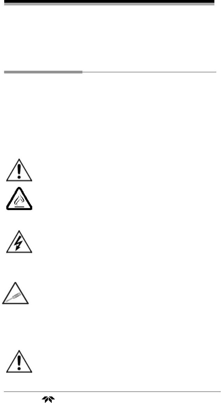
GENERAL WARNING/CAUTION: Refer to the
instructions for details on the specific danger. These cautions
warn of specific procedures which if not followed could cause
bodily Injury and/or damage the instrument.
CAUTION: HOT SURFACE WARNING: This warning is
specific to heated components within the instrument. Failure
to heed the warning could result in serious burns to skin and
underlying tissue.
WARNING: ELECTRICAL SHOCK HAZARD: Dangerous
voltages appear within this instrument. This warning is
specific to an electrical hazard existing at or nearby the
component or procedure under discussion. Failure to heed this
warning could result in injury and/or death from
electrocution.
Technician Symbol: All operations marked with this symbol
are to be performed by qualified maintenance personnel only.
NOTE: Additional information and comments regarding a
specific component or procedure are highlighted in the form
of a note.
CAUTION: THE ANALYZER SHOULD ONLY BE USED FOR THE
PURPOSE AND IN THE MANNER DESCRIBED IN
THIS MANUAL.
No
Symbol

Portable Trace Oxygen Analyzer
Teledyne Analytical Instruments v
IF YOU USE THE ANALYZER IN A MANNER OTHER
THAN THAT FOR WHICH IT WAS INTENDED,
UNPREDICTABLE BEHAVIOR COULD RESULT
POSSIBLY ACCOMPANIED WITH HAZARDOUS
CONSEQUENCES.
This manual provides information designed to guide you through
the installation, calibration operation and maintenance of your new
analyzer. Please read this manual and keep it available.
Occasionally, some instruments are customized for a particular
application or features and/or options added per customer requests.
Please check the front of this manual for any additional information in
the form of an Addendum which discusses specific information,
procedures, cautions and warnings that may be peculiar to your
instrument.
Manuals do get lost. Additional manuals can be obtained from TAI
at the address given in the Appendix. Some of our manuals are available
in electronic form via the Internet. Please visit our website at:
www.teledyne-ai.com.

Model 3110
vi Teledyne Analytical Instruments
Table of Contents
List of Figures............................................................................ viii
Introduction ................................................................................ 10
1.1 Introduction 10
1.2 Features 11
1.3 Method of Analysis 13
1.4 Micro-Fuel Cell 13
1.4.1 Cell Warranty 13
1.5 Accuracy and Response 14
1.6 Signal Output 14
1.7 Compact Packaging 14
Installation .................................................................................. 17
2.1 Charging the Batteries 17
2.2 Gas Connections 18
2.3 Sensor Installation 20
2.3.1 Installing a Trace Sensor 20
2.4 Calibration 21
2.4.1 Calibration Procedure for Trace Analysis 21
2.4.2 Bleeding the Regulator and Purging the Gas Line 22
2.5 Set the Sample Flow rate 22
2.6 External Signal 23
Operation .................................................................................... 24
3.1 Front Panel Interface 24
3.1.1 ENTER Key 24
3.1.2 ESCAPE Key 25
3.1.3 UP/DOWN Keys 25
3.2 Operation and Setup Screens and Menus 26
3.2.1 POWER ON Screen 27
3.2.2 HOME Screen 27

Portable Trace Oxygen Analyzer
Teledyne Analytical Instruments vii
3.2.3 DATE Screen 27
3.2.4 TIME Screen 28
3.2.5 STANDARD ALARM Screen 29
3.2.6 ALARM Enable 29
3.2.7 FS ALARM Screen 30
3.2.8 HI-LOW ALARM Screen 30
3.2.9 LTCH ALARM Screen 31
3.2.10 RANGE 1 Screen 32
3.2.11 RANGE 2 Screen 32
3.2.12 Range Screen 33
3.2.13 SPAN VALUE Screen 34
3.2.14 SPAN Screen 34
3.2.15 Filter Screen 35
3.2.16 LOG INTV Screen 36
3.2.17 LOG RESET & START Screen 36
3.2.18 LOG TRANSMIT Screen 37
3.2.19 POWER DOWN Screen 38
Maintenance & Troubleshooting................................................40
4.1 Routine Maintenance 40
4.2 Opening the Instrument Case 40
4.3 Replacing the Battery 40
4.4 Battery Power Supply Service 41
4.5 Cell Replacement 42
4.6 Cell Warranty 43
4.7 Temperature Compensation 44
4.8 Leak Testing 46
Appendix .....................................................................................48
A.1 Specifications 48
A.2 Spare Parts List 49
Index ............................................................................................50

Model 3110
viii Teledyne Analytical Instruments
List of Figures
Figure 2-1: Model 3110 Rear Panel.............................................. 18
Figure 3-1: Front Panel Keys ........................................................ 25
Figure 3-2: Available Menus and Their Sequence ........................ 26
Figure 4-1: Battery Charger Port on the Model 3110 .................... 42
Portable Trace Oxygen Analyzer
Teledyne Analytical Instruments ix
DANGER
COMBUSTIBLE GAS USAGE
WARNING
This is an intrinsically safe instrument which can be used in
hazardous areas. It is the customer's responsibility to ensure
safety especially when combustible gases are being
analyzed since the potential of gas leaks always exist.
The customer should ensure that the principles of operating
this equipment are well understood by the user. Misuse of
this product in any manner, tampering with its components,
or unauthorized substitution of any component may
adversely affect the safety of this instrument.
Since the use of this instrument is beyond the control of
Teledyne Analytical Instruments, referred as TAI, no
responsibility by TAI, its affiliates, and agents for damage or
injury from misuse or neglect of this equipment is implied or
assumed.

Introduction Model 3110
10 Teledyne Analytical Instruments
Introduction
1.1 Introduction
The Teledyne Analytical Instruments (TAI) Model 3110 Portable
Trace Oxygen Analyzer is a portable, intrinsically safe oxygen analyzer
capable of analyzing oxygen levels from 2 parts per million (ppm)
oxygen.
The instrument operates from internal rechargeable batteries and is
supplied with a universal AC charge adapter. Featuring quick
disconnect fittings for sample connections and a rugged lightweight
housing with handle, this versatile instrument can be brought to the
sample site and set up for analysis quickly and easily. Because of the
intrinsically safe design, once calibrated, the instrument can be
employed even in hazardous environments without compromise. The
Model 3110 incorporates a large standard feature list designed for
versatile, accurate oxygen analysis for a wide range of applications.
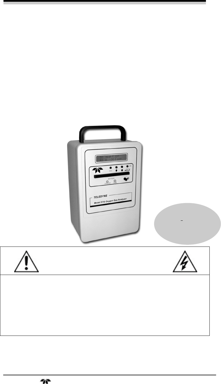
Figure 1-1 shows the standard Model 3110 Portable Trace Oxygen
Analyzer.
The microprocessor based Model 3110 instrument provides user
settable analysis ranges at the trace level. The range can be set from 0-2
ppm to 0-25% oxygen. In auto-ranging mode two ranges can be set and
the analyzer move between these ranges as required. The adjustment
resolution is 0.1 ppm for trace analysis.
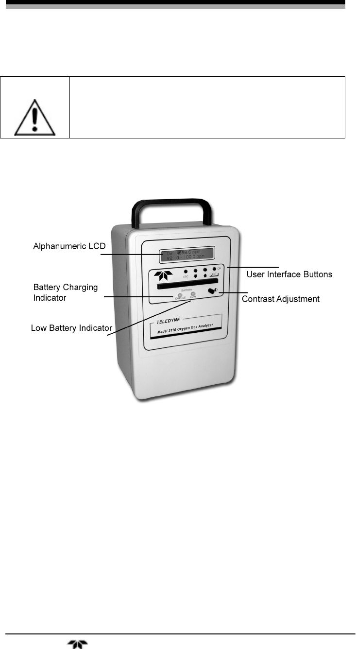
Sample oxygen is displayed on a 2-line 20 character alphanumeric
LCD display mounted on the front panel. Four buttons are used to
interface with the instrument and access all of the analyzer features.
Sample gas is introduced and vented via a pair of quick-disconnect
fittings that feature integral shutoff valves that automatically close when
the mating male fitting is withdrawn. The fittings are an integral part of
the measuring cell manifold.
Portable Trace Oxygen Analyzer Introduction
Teledyne Analytical Instruments 11
WARNING
Though the 3110 can be applied to monitor percent
oxygen, doing so will lead to more frequent sensor
replacement requirements.
Figure 1-1: Model 3110 Portable Trace Oxygen Analyzer
1.2 Features
This instrument is designed to be a versatile analytical instrument
and to perform reliably and accurately in analyzing oxygen
concentrations in gas mixtures from the ppm level through 25% oxygen.
The following features are standard on the Model 3110:
• Data Logger: The optional built-in data logging feature
allows the user to specify the time interval
between data recording sets. The date,
time, and oxygen concentration readings
are stored in internal RAM at the user
specified interval. The data set can be

Introduction Model 3110
12 Teledyne Analytical Instruments
downloaded using the instrument’s
optional RS-232 interface.
• Display: A 2-line 20 character alphanumeric LCD
on the front panel displays data and
operational information through various
screens. The contrast is adjustable for
various lighting conditions.
• Four-Button User Interface: Operation is performed using the
four front panel mounted buttons. These
buttons are used to enter data, select items
and move through operational screens that
appear on the display.
• Universal AC Charge Adapter: The rechargeable batteries can
be recharged without removing them from
the instrument. The charger operates over
the range of 100-240 VAC.
• LEDs: Two front panel mounted LEDs are used
to indicate low battery condition and when
the battery is recharging.
• Contrast Control: This feature allows the user to easily
adjust the contrast of the display for
optimum viewing under different lighting
conditions. The adjustment is made using
a front panel control dial.
• Auto-ranging: The user is able to specify two analytical
ranges for analysis in the auto mode. The
Model 3110 will automatically switch
between these ranges depending on the
oxygen level.
• Percent of Range Voltage Output: An optional 0-1 VDC
output is available that represents the
percentage of the current analysis range.
• Real-time Clock: This feature allows the Model 3110 to date
and time stamp the data set recorded on
the data logger. It uses a 24 hour clock.

Portable Trace Oxygen Analyzer Introduction
Teledyne Analytical Instruments 13
• Quick Disconnect Fittings: Dual self-sealing quick disconnect
fittings are installed for making easy
sample connections.
1.3 Method of Analysis
The sample oxygen is measured by a unique electrochemical
transducer which functions as a fuel cell; in this instance, the fuel is
oxygen. Oxygen diffusing into the cell reacts chemically to produce an
electrical current that is proportional to the oxygen concentration in the
gas phase immediately adjacent to the transducer’s sensing surface. The
linear, but minute signal produced by the transducer from oxygen is
amplified by a two-stage amplifier. The O2 sensor output signal is
digitized and fed to the microprocessor. Additional signal conditioning
and temperature compensation are handled electronically and
appropriate signals are directed to the display and output ports.
1.4 Micro-Fuel Cell
The micro-fuel cell (U.S. Pat. Nos. 3,767,552 and 3,668,101) is a
sealed electrochemical transducer with no electrolyte to change or
electrodes to clean. When the cell reaches the end of its useful life, it is
removed, properly disposed of, and replaced with a new cell. The life of
the cell is warranted by TAI (see below).
The cell is specific for oxygen and is not sensitive to flow rate or
reducing agents such as hydrocarbons, carbon monoxide, sulfur dioxide,
etc. In the absence of oxygen, no current is produced; thus, no zeroing is
required.
1.4.1 Cell Warranty
The Class B2-C, A2C, B2C-XL and Insta Trace micro-fuel cells
can be used in the Model 3110 and are warranted for six (6) months
from the date of shipment.
With regard to spare cells, service time starts when the cell is
removed from its shipping package. You should stock only one spare
cell per instrument at a time.
If a cell was working satisfactorily but ceases to function before the
warranty period expires, the sensor will be replaced at no cost.

Introduction Model 3110
14 Teledyne Analytical Instruments
If you have a warranty claim, return the cell in question to the
factory for evaluation. If it is determined that failure is due to faulty
workmanship or material, the cell will be replaced at no cost to you.
WARNING: EVIDENCE OF DAMAGE DUE TO TAMPERING OR
MISHANDLING WILL RENDER THE CELL
WARRANTY NULL AND VOID.
The Model 3110 is designed to meet Factory Mutual standards for
intrinsically safe for Class I, Division I, Groups A, B, C and D
hazardous locations. (Approval pending at time of manual printing.)
This safety feature does not apply when the instrument is being
charged with the 100- 240 VAC external charge adapter. The instrument
should be removed from hazardous areas when the batteries are being
charged.
Note: Do not use the analyzer when the battery charge is low.
1.5 Accuracy and Response
The Model 3110 provides monitoring accuracies of ±2% of full
scale or ±1 ppm, whichever is greater, at constant temperature.
With a sample flow rate of 1 SCFH, a 90% response can be realized
in 60 seconds. The response time on the 3110 is limited by the filter
setting.
1.6 Signal Output
The standard 0-1 VDC output has a 100 ohm impedance and is
suitable for driving external devices that have an input impedance of
10,000 Ω or more. The signal output is available from a port on the rear
panel.
1.7 Compact Packaging
The instrument is housed in 6 1/8" × 9 ½" × 5 5/8" (156 × 241 ×
143 mm) aluminum case that is equipped with a carrying handle and
foot pads. Unlike analog instruments where uneven positioning may

Portable Trace Oxygen Analyzer Introduction
Teledyne Analytical Instruments 15
affect meter accuracy, the Model 3110 can be used in any position
without interference.

Introduction Model 3110
16 Teledyne Analytical Instruments
Intentionally left blank.

Portable Trace Oxygen Analyzer Installation
Teledyne Analytical Instruments 17
Installation
The Model 3110 Trace Oxygen Analyzer is designed to be portable
and easy to setup and configure. To setup the analyzer:
• Read the Manual
• Charge the battery
• Install the sample and vent gas lines
• Install the trace sensor and purge the analyzer
• Calibrate the analyzer
• Set the sample gas flow rate
2.1 Charging the Batteries
The unit is powered by 2 Intrinsically Safe rated sub-C Ni-Cd
batteries and is shipped with batteries fully charged. The batteries,
however, will require periodic recharging. For recharging, access to an
AC power source of 100 to 240 volt, 50/60 Hz will be required and the
instrument should not be recharged in a hazardous area. Connect the
universal AC charger adapter supplied with the instrument to the AC
power outlet. Plug the other end of the charger into the port on the rear
panel as shown in Figure 2-1. The green charge indicator LED should be
illuminated to indicate that the unit is charging.
To fully recharge a set of batteries will take approximately 16
hours. The instrument should not be left on the charger for longer than
20 hours nor should the charger be left attached to the instrument when
the unit is not charging. The Model 3110 cannot be operated while the
battery charger is attached.
CAUTION: DO NOT CHARGE THE BATTERY IN A HAZARDOUS
AREA. THE INTRINSICALLY SAFE CLASSIFICATION
OF THIS INSTRUMENT DOES NOT APPLY WHEN
THE CHARGER IS ATTACHED TO THE
INSTRUMENT. REMOVE THE INSTRUMENT TO A
NON-HAZARDOUS AREA BEFORE CONNECTING
THE BATTERY CHARGER TO THE INSTRUMENT.
Installation Model 3110
18 Teledyne Analytical Instruments
The unit can operate continuously for approximately 4 days on a set
of fully charged batteries. If more frequent charging is required, the
batteries are approaching the end of their useful life and should be
replaced. See Battery Replacement in Section 4.3 of this manual.
A low battery condition is indicated by a blinking red Low Battery
LED on the front panel. This will also cause the display to flicker along
with the blinking LED due to the power drain and low battery condition.
At this point the unit should be removed from service and the batteries
recharged.
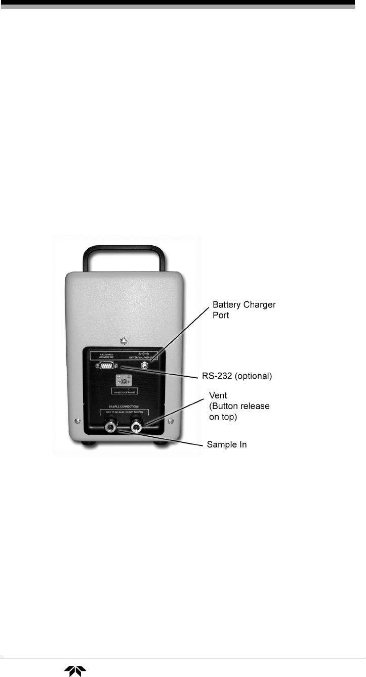
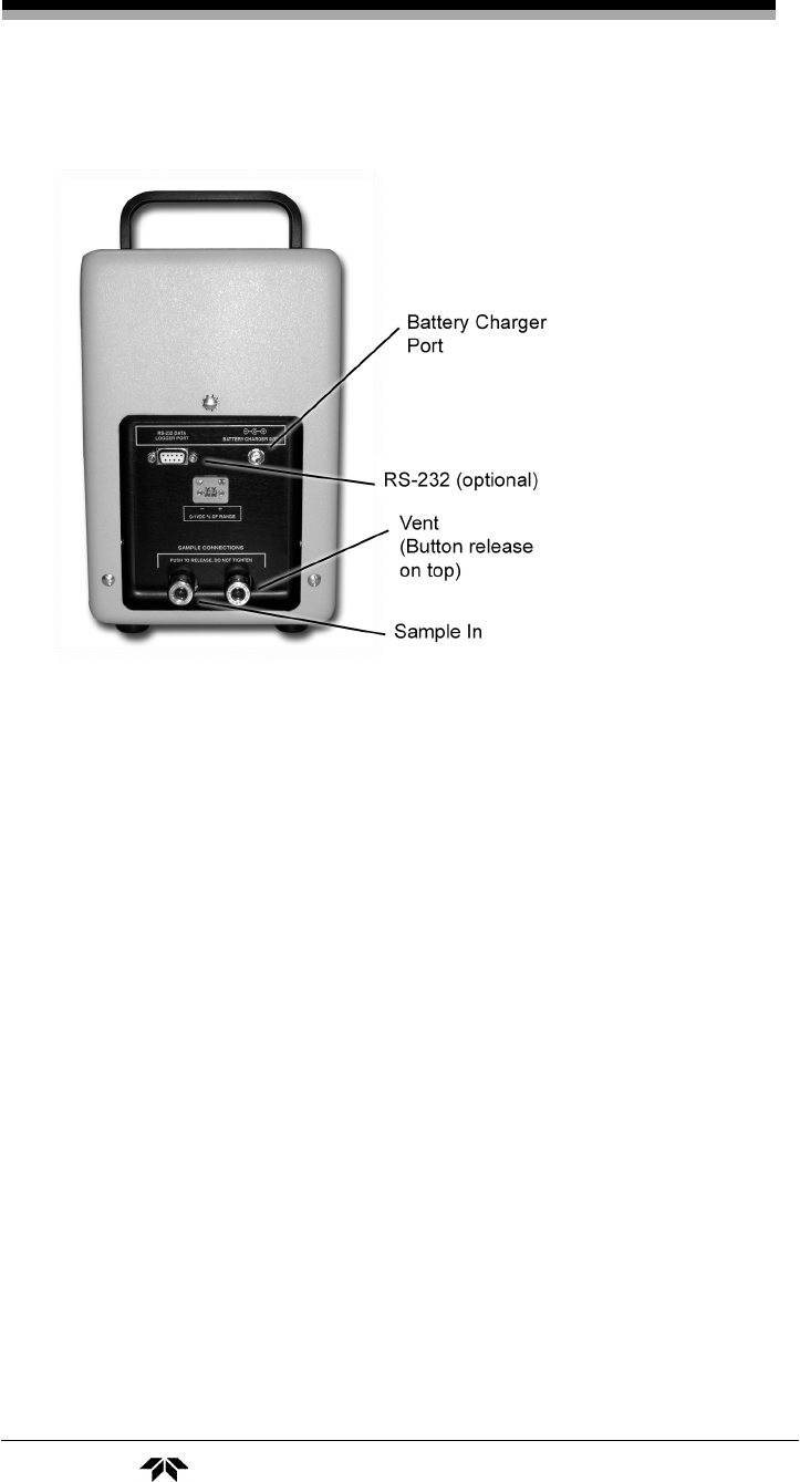
Figure 2-1: Model 3110 Rear Panel
2.2 Gas Connections
The customer must provide a means of controlling the pressure and
flow rate of the sample and zero gas. For positive pressure applications,
TAI suggests a simple throttle valve installed in the sample line between
the sample point and the analyzer. The flow rate should be limited to
between 0.2 and 2.5 SCFH. The sample in port is used for both sample
Portable Trace Oxygen Analyzer Installation
Teledyne Analytical Instruments 19
and calibration gas. For atmospheric pressure sampling, connect a pump
and flow control valve downstream from the analyzer and draw (rather
than push) the sample through the instrument.
IMPORTANT: IF A PRESSURE REGULATOR IS USED, IT MUST
HAVE A METALLIC DIAPHRAGM. REGULATORS
WITH ORGANIC OR PLASTIC DIAPHRAGMS ARE
PERMEABLE TO OXYGEN AND, IF USED IN THE
SAMPLING SYSTEM, WILL LEAD TO HIGH OXYGEN
READINGS.
The instrument is shipped with a gas sampling and calibration kit.
This includes a 12” piece of clear tubing with a quick disconnect line for
use as a sample return or vent line plus 2 quick disconnect fittings to be
installed on the sample and calibration lines. These fittings employ ¼”
tube fittings which can be removed to reveal a 1/8” NPT internal thread.
It is important in trace analysis applications to use metal for all
wetted components of the sample system. This includes gas lines, filters,
pump housing, diaphragms and any components in contact with the
sample gas. Plastic tubing and parts will result in slow and inaccurate
measurements at the ppm level.
There are two quick disconnect fittings installed on the rear panel
for mating the instrument with the sample or calibration gas and the vent
line. As shown in Figure 2-1, each fitting has a button which when
depressed allows the rapid detachment of the gas line from the
instrument. It is not necessary to press the button when inserting the
line, just push the male fitting into the mating connector. When a line is
removed, an internal seal prevents gas escape from the female sections
of the fitting.
To avoid pressurizing the sensor, the vent line should be
installed first and removed last.
In setting up the sample lines, any valves used to set the sample
flow or filters must be located on the sample in line. Do not place any
valves or restrictions on the vent line except as noted above for
atmospheric pressure sampling when using a downstream pump. Doing
so would increase the sensor operating pressure and result in inaccurate
analysis.

Installation Model 3110
20 Teledyne Analytical Instruments
For trace analysis applications, a flowmeter should be installed in
the vent line but it should not incorporate any control valves or
restrictive devices.
2.3 Sensor Installation
The Model 3110's trace sensor requires that the instrument lines be
immediately purged with zero gas after installing the cell.
2.3.1 Installing a Trace Sensor
Prior to installing the trace sensor, make sure the analyzer is ready
to purge with zero gas. Connect the vent line to the analyzer then
connect the zero gas line to the sample in port. Set the zero gas flow rate
between 0.2 and 2.5 SCFH.
Prior to using any bottled gas for calibration or purge, it is good
practice to bleed the regulator and sample line to remove any traces of
trapped air. See Section 2.4.3 Bleeding the Regulator and Purging the
Gas Line.
Once the vent and zero gas lines are attached and the lines bleed,
proceed to install the trace sensor as follows:
1. Remove the cell holder cap from the bottom of the
instrument.
2. Remove the outer packaging from the sensor.
3. Grab the shorting plug on the top of the sensor and pull it
free prior to removing the sensor from its packaging.
4. Remove the packaging and rapidly place the sensor on the
top of the cell holder cap with the concentric gold rings
facing up.
5. Screw the cell holder cap and sensor into the bottom of the
analyzer.
Note: Minimize the time the sensor is exposed to air.
6. Start the purge flow through the analyzer and purge
overnight before calibrating the unit.

Portable Trace Oxygen Analyzer Installation
Teledyne Analytical Instruments 21
2.4 Calibration
Calibration involves using a span gas to set the span of the
instrument. The proper span gas concentration depends on the range that
the instrument will be used on. The correct concentration should be 80-
90% of the range used. For instance, if the analyzer is to be used on a
range of 0-150 ppm oxygen, then a span gas should be prepared with
120-135 ppm oxygen in nitrogen.
2.4.1 Calibration Procedure for Trace Analysis
To calibrate the Model 3110, the instrument must be fitted with a
trace sensor. The instrument must also be purged overnight using a zero
gas (a pure gas with no oxygen, typically O2 free N2) before calibrating.
For A-2C type cells, match the CO2 content in the span gas to that of the
sample gas.
To calibrate the analyzer for trace analysis:
1. Purge the analyzer overnight.
2. Purge the calibration gas sample line, regulator, and control
valve. See Section 2.4.3.
3. Set the calibration gas flow rate to 1 SCFH.
4. Attach the vent line followed by the span gas line using the
quick disconnect fittings.
5. Navigate to the SPAN VALUE screen (see Section 3.2.13)
and set the span value to the known oxygen concentration in
ppm of the span gas.
6. Observe the oxygen reading on the screen to determine when
the reading has stabilized.
7. Navigate to the SPAN screen and select SPAN: START.
8. When the screen changes and displays SPAN: FINISH, select
SPAN: FINISH to set the span.
9. Allow the span gas to flow for several minutes to verify the
proper span setting.
10. Calibration is complete. Remove the span gas line first
followed by the vent line.

Installation Model 3110
22 Teledyne Analytical Instruments
2.4.2 Bleeding the Regulator and Purging the Gas Line
When using bottled gas (gas cylinder) as a calibration gas for trace
analysis applications, the regulator and sample lines must be bled to
remove traces of trapped air. Otherwise air that is trapped in the lines
especially between the regulator and cylinder will result in a lengthening
of the calibration time.
To bleed the regulator and sample line:
1. Attach the regulator to the gas cylinder. Then attach a sample
line with a flow control/shut off valve preferably at the far
end of the sample line.
2. Open the shut off valve slightly, and then open the valve on
the gas cylinder.
3. Adjust the regulator to the desired pressure (usually 5 psi)
then close the cylinder valve.
4. Open the cylinder valve to pressurize the regulator fully then
close the cylinder valve again.
5. Open the sample flow control valve and allow the gas to
bleed down and vent to a safe area. Observe the secondary
gauge (low pressure side) on the regulator. As the low
pressure gauge starts to fall, close the sample flow control
valve.
6. Repeat steps 4 and 5 seven (7) times.
The sample delivery system is now purged and ready for calibration
or analysis. Keep the cylinder valve open to maintain system
pressurization.
Note: Make sure there are no leaks in the sample line and
regulator connections. Check also the cylinder connection
for leaks.
2.5 Set the Sample Flow rate
Once the system has been calibrated, the instrument can be brought
to the analysis site and the sample gas line can be connected to the unit.
Using the quick disconnect fittings supplied; connect the vent line
followed by the sample line to the rear panel. See Figure 2-1.
Once the sample gas is flowing, set the flow rate to 0.2-2.5 SCFH.

Portable Trace Oxygen Analyzer Installation
Teledyne Analytical Instruments 23
2.6 External Signal
The standard 0-1 VDC output signal represents the percentage of
the current range. For instance, if the range was set for 0 to 10 ppm, then
0.1 V would represent 1 ppm, 0.2V would be 2 ppm; 0.3V would be 3
ppm etc.
This output signal, when installed, is accessible from the rear panel.
The output signal has an input impedance of 100Ω.

Operation Model 3110
24 Teledyne Analytical Instruments
Operation
The micro-fuel cell is not installed in the analyzer prior to
shipment. It is be a separate item that is to be installed according the
procedure in section 2.3 of this manual. Once the cell is installed and
purged down with zero gas, the integral shut-off valves in the quick
disconnect sample fittings, if not disturbed, will maintain this inert
atmosphere within the manifold indefinitely.
Turning the instrument on by pressing the ENTER key will power
the display and show the power on screen briefly. The display will then
change to indicate the residual oxygen concentration within the internal
sample passageways if no sample line is attached.
Note: To extend cell life and minimize the time required to make
the next analysis, the instrument should always be purged
with an oxygen free inert gas prior to being taken out of
service for standby or storage.
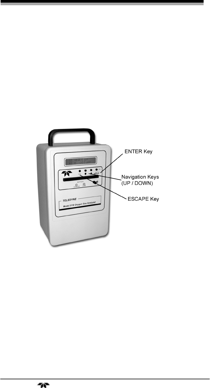
3.1 Front Panel Interface
The Model 3110 is controlled from the keys on the front panel and
is shown in Figure 3-1. These keys are also used to setup the instrument
for your application. The keys are:
• ENTER/ON
• ESC
• UP/DOWN
3.1.1 ENTER Key
The ENTER key is context sensitive. It is used as follows:
• Powering ON or OFF—Pressing the ENTER key turns the
power ON. The ENTER key is also used the power OFF
from within the POWER OFF screen.
• Enter SETUP—In certain menus, pressing the ENTER key
selects a setup screen for that particular function. Navigation
Portable Trace Oxygen Analyzer Operation
Teledyne Analytical Instruments 25
arrows on the left and right of the bottom line identify these
screens as setup screens by changing from UP/DOWN to
LEFT/RIGHT. The setup screens also blink.
• Select a value—When multiple options or values exist for a
function, pressing ENTER selects the currently displayed
option.
• Save changes—If a value or option has been modified,
pressing ENTER saves the change and brings you back to the
previous screen.
Figure 3-1: Front Panel Keys
3.1.2 ESCAPE Key
The ESCape key is used to exit a setup menu without saving any
changes made to that screen. The values will revert to the last value
saved for that entry.
3.1.3 UP/DOWN Keys
The UP/DOWN keys are used to:
• Navigate from one screen to another
• Toggle between multiple options within a menu
Operation Model 3110
26 Teledyne Analytical Instruments
• Increment or decrement a value
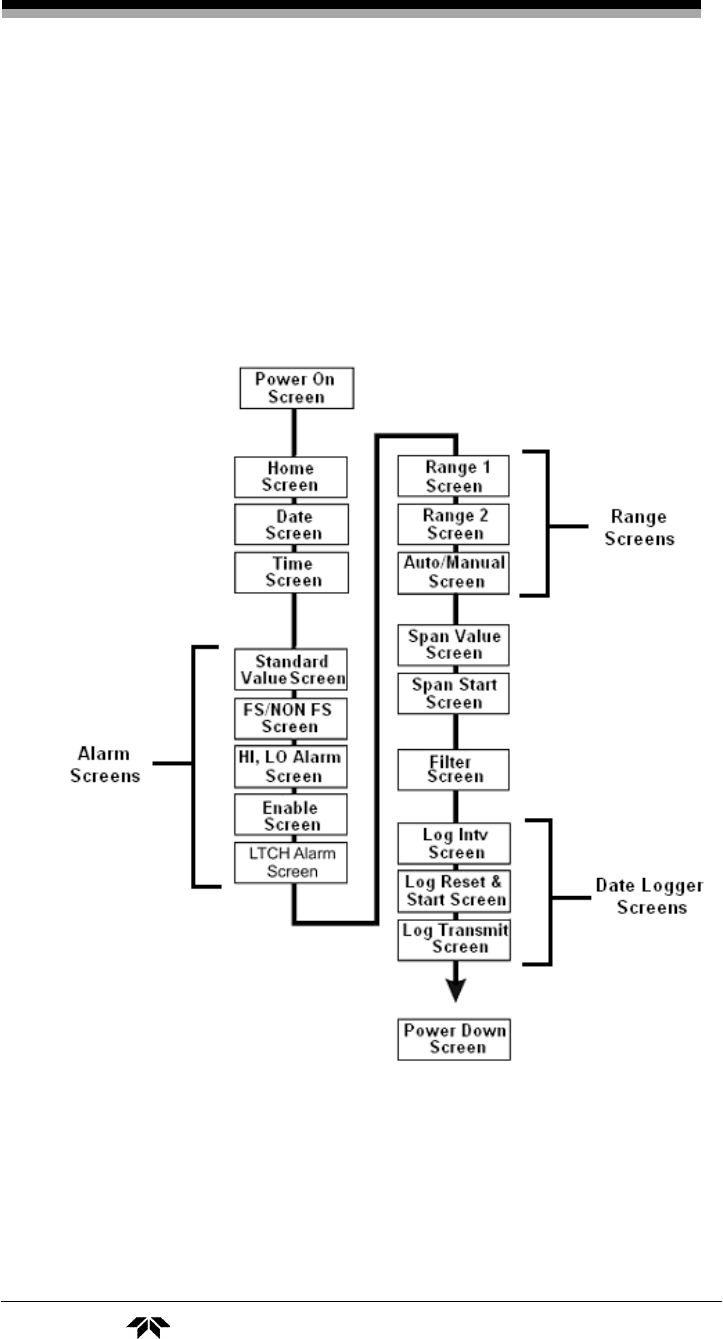
3.2 Operation and Setup Screens and Menus
The Model 3110 operation and setup functions are arranged in a set
of 15 menus. All but the POWER ON screen are accessible via the
UP/DOWN keys. Figure 3-2 shows the available menus and the
sequence of screens when scrolling.
Figure 3-2: Available Menus and Their Sequence
Portable Trace Oxygen Analyzer Operation
Teledyne Analytical Instruments 27
3.2.1 POWER ON Screen
The POWER ON screen automatically appears on the display when
the unit is first powered up. The display appears briefly and shows the
model number and software version. After a few seconds the display
reverts to the HOME screen.
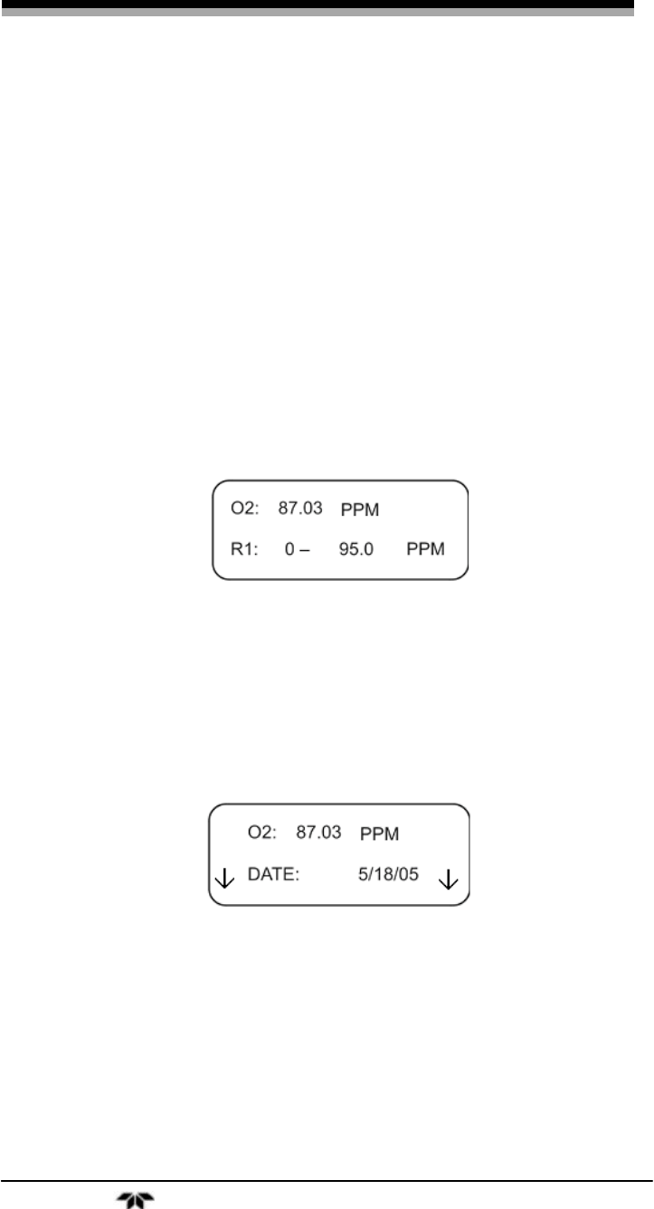
3.2.2 HOME Screen
The HOME screen displays the oxygen concentration at the level of
the current range (ppm or %). The concentration is shown in the upper
line the current range is indicated on the second line.
Note: In almost all of the available screens, the first line displays
the oxygen concentration.
3.2.3 DATE Screen
Use the UP/DOWN keys to navigate to the DATE screen. The
second line of the DATE screen displays the current date and is used by
the data logger for date stamping data records. The currently set date is
displayed on the second line of the display.
To change the currently set date:
1. Press ENTER to enter the date setup function. Note the
navigation arrows that appear on the left and right sides of
the display change from UP/DOWN to pointing
LEFT/RIGHT.

Operation Model 3110
28 Teledyne Analytical Instruments
2. Use the UP/DOWN keys to alter the month. Then press
ENTER. The cursor will move over to the next editable field.
3. Use the UP/DOWN keys to alter the day. Then press
ENTER. The cursor will move over to the next editable field.
4. Use the UP/DOWN keys to alter the year. Then press
ENTER.
5. Press ENTER again to save the current date and
automatically return to the DATE screen.
At any time you can press the ESC key to abort the entry and return
to the DATE screen.
3.2.4 TIME Screen
Use the UP/DOWN keys to navigate to the TIME screen. The
second line of the this screen displays the current time in 24 hour
military format. This information is used by the data logger for time
stamping data records. The currently set time is displayed on the second
line of the display.
To change the currently set time:
1. Press ENTER to enter the time setup function. Note the
navigation arrows that appear on the left and right sides of
the display change from UP/DOWN to pointing
LEFT/RIGHT.
2. Use the UP/DOWN keys to alter the hour field. Then press
ENTER. The cursor will move over to the next editable field.
3. Use the UP/DOWN keys to alter the minute field. Then press
ENTER. The cursor will move over to the next editable field.
4. Use the UP/DOWN keys to alter the seconds field. Then
press ENTER.
5. Press ENTER again to save the current time and
automatically return to the TIME screen.
Portable Trace Oxygen Analyzer Operation
Teledyne Analytical Instruments 29
At any time you can press the ESC key to abort the entry and return
to the DATE screen.
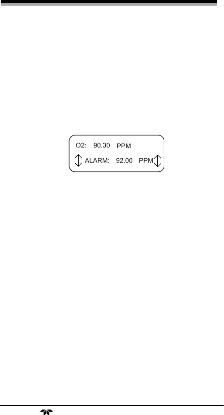
3.2.5 STANDARD ALARM Screen
Note: Alarm relays are not included on the standard version of the
3110.
During an alarm a blinking “AL” will appear in the upper right
corner of the display. Use the UP/DOWN keys to navigate to the
STANDARD ALARM screen. This screen displays the alarm setpoint on
the lower line. You can change the setpoint and on this screen.
To change the alarm setpoint or toggle between ppm and %:
1. Press ENTER to enter the alarm setup function. Note the
navigation arrows that appear on the left and right sides of
the display change from UP/DOWN to LEFT/RIGHT
2. Use the UP/DOWN keys to alter the value in the setpoint
field. Then press ENTER to accept this new value. The
cursor will move over to the next editable field.
3. Use the UP/DOWN keys to toggle between PPM or % then
press ENTER to accept the change.
4. Press ENTER again to save the setpoint changes and return
to the STANDARD ALARM screen.
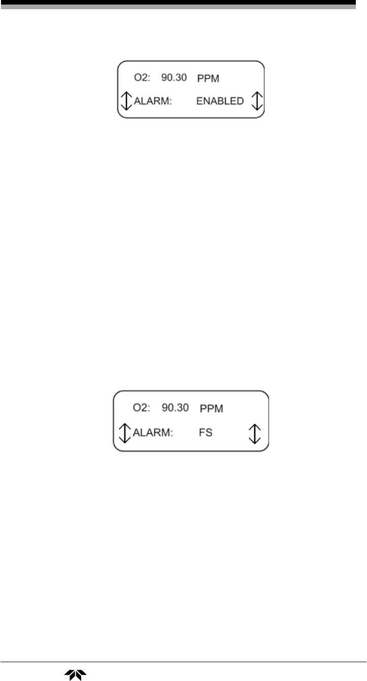
3.2.6 ALARM Enable
The next four screens determine the characteristics of the alarm:
whether it is on or off, failsafe or non-failsafe, HI or LOW activating, or
latching or non-latching in its operation.
From the ALARM ENABLE screen you can set whether the alarm is
on or off.
Operation Model 3110
30 Teledyne Analytical Instruments
To enable or disable the alarm:
1. Use the UP/DOWN keys to navigate to the ALARM ENABLE
screen. Then press ENTER to enter the alarm setup screen.
2. Use the UP/DOWN keys to toggle between ENABLED or
DISABLED. Then press ENTER to accept the displayed
status.
3. Press ENTER again to save the alarm status and return to the
ALARM ENABLE screen.
3.2.7 FS ALARM Screen
This screen indicates how the alarm relays activate—failsafe or
non-failsafe. In failsafe mode the relays are energized when analyzer is
NOT in alarm mode. In non-failsafe mode the alarm relay energizes
when the analyzer goes into alarm mode. You can change the alarm
relay behavior by entering the FS ALARM setup screen.
To toggle between failsafe and non-failsafe operation:
1. Use the UP/DOWN keys to navigate to the FS ALARM
screen. Then press ENTER to enter the setup screen.
2. Use the UP/DOWN keys to toggle between FS or NON-FS
options. Then press ENTER to accept the displayed status.
3. Press ENTER again to save the alarm status and return to the
FS ALARM screen.
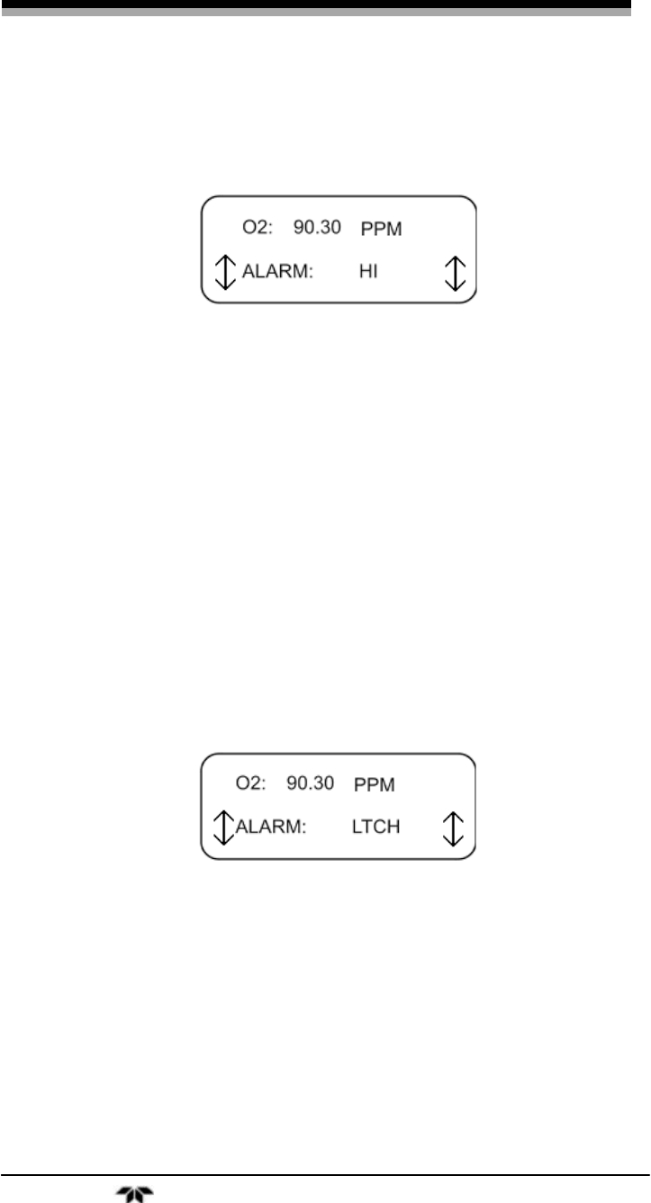
3.2.8 HI-LOW ALARM Screen
The HI-LO screen indicates how the Model 3110 alarm functions.
The alarm on the Model 3110 can be set up as either a HI alarm or LO
Portable Trace Oxygen Analyzer Operation
Teledyne Analytical Instruments 31
alarm. A HI alarm activates when the oxygen concentration rises above
the setpoint. The LO alarm activates when the oxygen concentration
falls below the setpoint.
To set the alarm as either a HI or LO alarm:
1. Use the UP/DOWN keys to navigate to the HI-LO ALARM
screen. Then press ENTER to enter the setup screen.
2. Use the UP/DOWN keys to toggle between HI and LO
option. Then press ENTER to accept the displayed status.
3. Press ENTER again to save the alarm status and return to the
HI-LO ALARM screen.
3.2.9 LTCH ALARM Screen
The alarm on the Model 3110 can be set up as latching or non-
latching. A latching alarm, once triggered, will remain in alarm status
until recognized and reset. Even if the concentration changes back to a
non-alarm concentration, a latched alarm will remain in alarm status. A
non-latching alarm will cease to alarm when the concentration falls or
rises to a non-alarm value.
To set the alarm to either latching or non-latching:
1. Use the UP/DOWN keys to navigate to the LTCH ALARM
screen. Then press ENTER to enter the setup screen.
2. Use the UP/DOWN keys to toggle between LTCH and NON-
LTCH options. Then press ENTER to accept the displayed
status.
3. Press ENTER again to save the alarm status and return to the
LTCH ALARM screen.
Operation Model 3110
32 Teledyne Analytical Instruments
To reset a latched alarm that has triggered use the ALARM
ENABLE screen and temporarily DISABLE the alarm. See Section
3.2.6. This will restore the alarm to it previous non-alarm condition.
Note: A latched alarm can only be reset when the concentration
falls or rises to a non-alarm value. (It can be disabled)
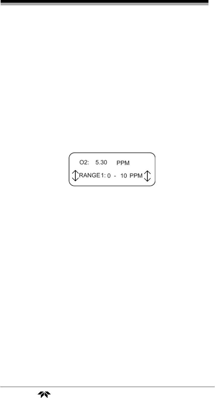
3.2.10 RANGE 1 Screen
The Model 3110 is capable of using two user defined ranges in the
auto-ranging mode however, if the instrument is used in manual mode
(see Section 3.2.12), only RANGE 1 is recognized.
The RANGE 1 screen displays the current range setting for range 1
on the bottom line of the display.
To define or change range 1:
1. Use the UP/DOWN keys to navigate to the RANGE 1 screen.
Then press ENTER to enter the setup screen.
2. Use the UP /DOWN keys to change the value.
3. The UP/DOWN keys will cycle through the ppm values.
4. Press ENTER to accept the displayed unit and return to the
RANGE 1 screen.
Note: The range setting resolution is 0.1 PPM for trace analysis.
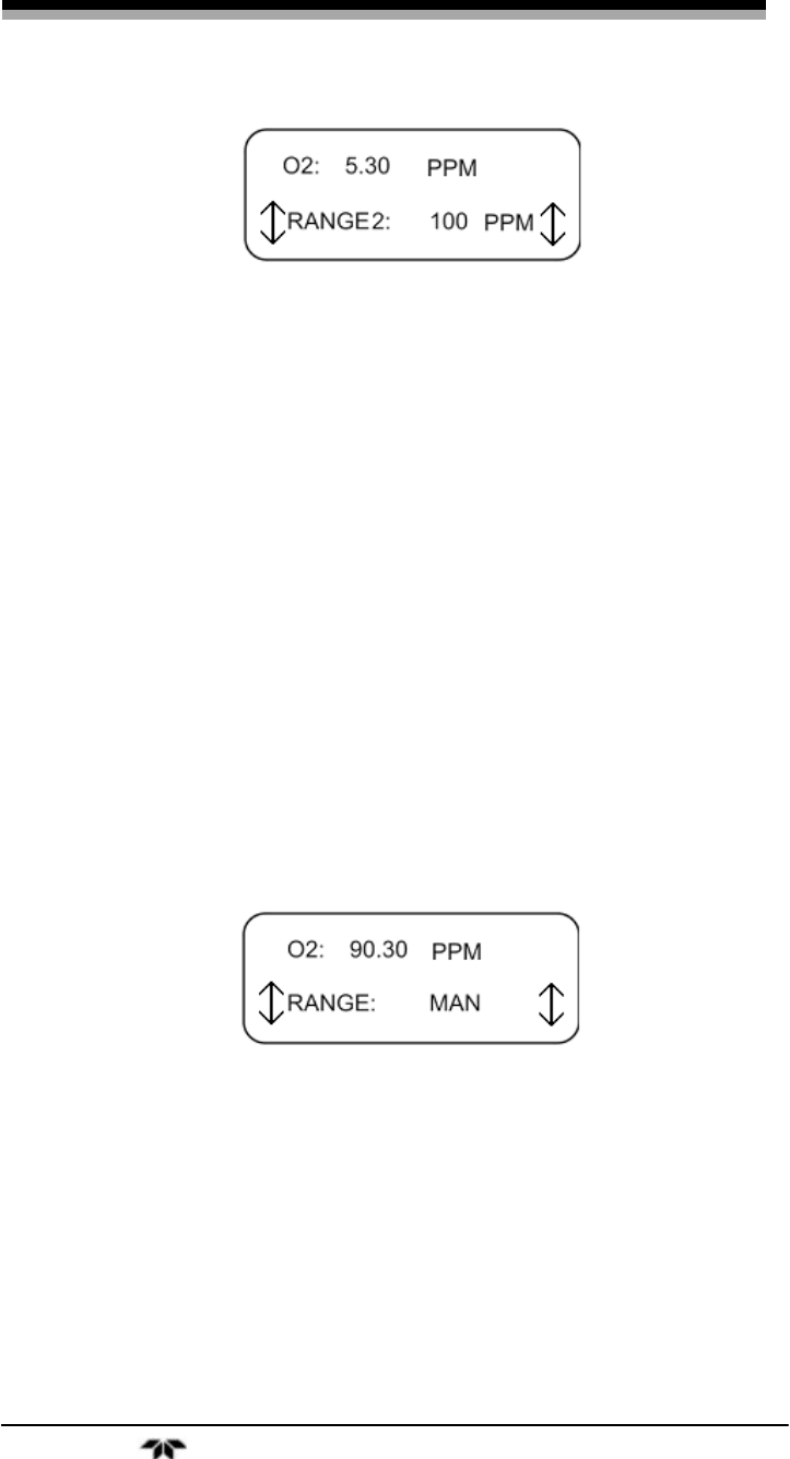
3.2.11 RANGE 2 Screen
The RANGE 2 screen displays the current range setting for range 2
on the bottom line of the display. This range is used only when the
instrument is set for auto-ranging. See Section 3.2.12. In manual mode
this range is ignored.
Portable Trace Oxygen Analyzer Operation
Teledyne Analytical Instruments 33
To define or change range 1:
1. Use the UP/DOWN keys to navigate to the RANGE 2 screen.
Then press ENTER to enter the setup screen.
2. Use the UP /DOWN keys to change the initial value. Press
ENTER to accept the displayed value and to return to the
RANGE 2 screen.
Note: The range setting resolution is 0.1 PPM for trace analysis.
Note: Make sure that the instrument is set for auto-ranging if you
expect to use this analysis range.
3.2.12 Range Screen
The RANGE screen indicates whether the instrument is currently in
manual or auto-ranging mode. When in manual mode, only range 1 is
available. In auto-ranging mode, range 1 and range 2 are available and
the instrument will automatically switch between ranges as dictated by
the analysis.
To switch between manual and auto-ranging modes:
1. Use the UP/DOWN keys to navigate to the RANGE screen.
Then press ENTER to enter the setup screen.
2. Use the UP/DOWN keys to toggle between MAN and AUTO
for the range mode. Press ENTER to accept the displayed
mode.
3. Press ENTER again to return to the RANGE screen.
Operation Model 3110
34 Teledyne Analytical Instruments
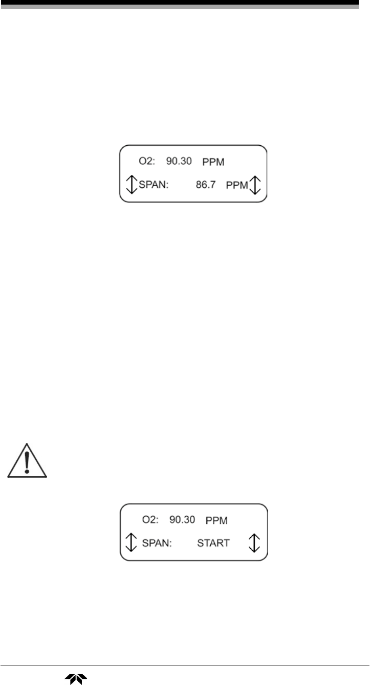
3.2.13 SPAN VALUE Screen
The SPAN VALUE screen displays the oxygen concentration of the
span gas used for calibration. This is not a measured value; it is the
known span gas concentration that is input to the analyzer by the
operator.
To change the span gas concentration:
1. Use the UP/DOWN keys to navigate to the SPAN VALUE
screen. Then press ENTER to enter the setup screen.
2. Use the UP /DOWN keys to change the span value. Press
ENTER to accept the displayed value and to return to the
SPAN VALUE screen.
3.2.14 SPAN Screen
This screen is used to perform a span calibration on the Model
3110. The appropriate span value must have already been input to the
instrument. See Section 3.2.13 for entering a span value into the
analyzer.
CAUTION: THE CORRECT SPAN VALUE MUST BE ENTERED
INTO THE INSTRUMENT THAT CORRESPONDS TO
THE ACTUAL SPAN GAS USED. FAILURE TO ENTER
THE PROPER VALUE WILL RESULT IN ERRONEOUS
READINGS.
Note: The filter should be set to a low value to avoid errors
during span setting. Allow the oxygen reading to become stable
prior to setting the span.
To perform a span calibration:
Portable Trace Oxygen Analyzer Operation
Teledyne Analytical Instruments 35
1. Use the UP/DOWN keys to navigate to the SPAN screen.
Then press ENTER to start the span calibration.
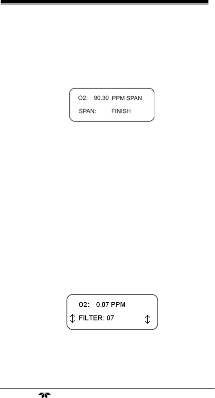
Once the span calibration has begun the screen changes to reveal a
span finish selection.
2. When the FINISH selection appears, press ENTER to end the
span calibration. The analyzer will accept the calibration and
return to the HOME screen.
Note: After successfully performing a span calibration, you are
returned directly to the HOME screen rather than back to
the previous menu.
3.2.15 Filter Screen
The 3110 includes user adjustable filter. The filter has settings 1-
10. Setting 1 is the least amount of filtering and 10 is the highest level of
damping. The filter is used to reduce the noise level of the O2 readings.
More filtering is required for lower trace ranges such as 10 ppm. Adding
filtering will slow down analyzers response to changing O2 levels. The
lowest effective level of filtering should always selected. The filter level
should be lowered to 1or 2 when setting the span to avoid delays. For a
0-10 ppm range a filler setting or 6 or 7 should typically provide good
results.
Operation Model 3110
36 Teledyne Analytical Instruments
To use this feature:
1. Use the UP/DOWN keys to navigate to the FILTER screen.
Then press ENTER to enter the setup screen.
2. Use the ENT/ON key to change the filter to the active mode.
The arrows will point left and right and the filter setting will
blink.
3. Use the UP/DOWN keys to select the desired setting.
4. Select the ENT/ON key to save the setting and to return to
the non-active mode on the filter screen.
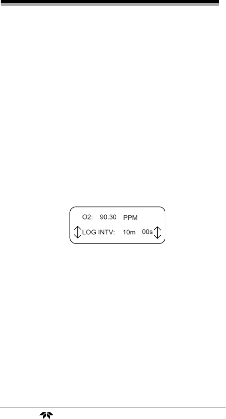
3.2.16 LOG INTV Screen
This screen indicates the time interval between data samples taken by
the data logger. The interval can be set between 1 second (00m 01sec) to 60
minutes (60m 00sec) in increments of 1 second.
To change the interval between data samples:
1. Use the UP/DOWN keys to navigate to the LOG INTV
screen. Then press ENTER to enter the setup screen.
2. Use the UP /DOWN keys to change the interval value. The
value of the seconds will increase or decrease followed by
the minutes. Press ENTER to accept the displayed value and
return to the LOG INTV screen.
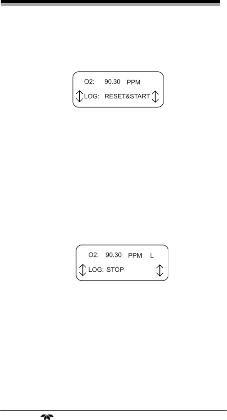
3.2.17 LOG RESET & START Screen
Once a log interval has been input, the LOG RESET & START
screen is used to start the data logger.
The data logger has a 3200 record capacity and each record uses 10
bits of data. The data set is retained until it is reset by using the START
Portable Trace Oxygen Analyzer Operation
Teledyne Analytical Instruments 37
RESET menu again. The data set can be downloaded using the LOG
TRANSMIT screen (see Section 3.2.17).
To start the data logger:
1. Use the UP/DOWN keys to navigate to the LOG RESET &
START screen and press ENTER.
2. When the screen begins to blink press ENTER again to start
the data logger. Once the data logger has started, the screen
changes RESET&START to STOP. During logging a
blinking “L” appears in the upper left corner of the screen.
To stop the data logger:
1. Press ENTER to stop the data logger and return to the LOG
RESET & START screen.
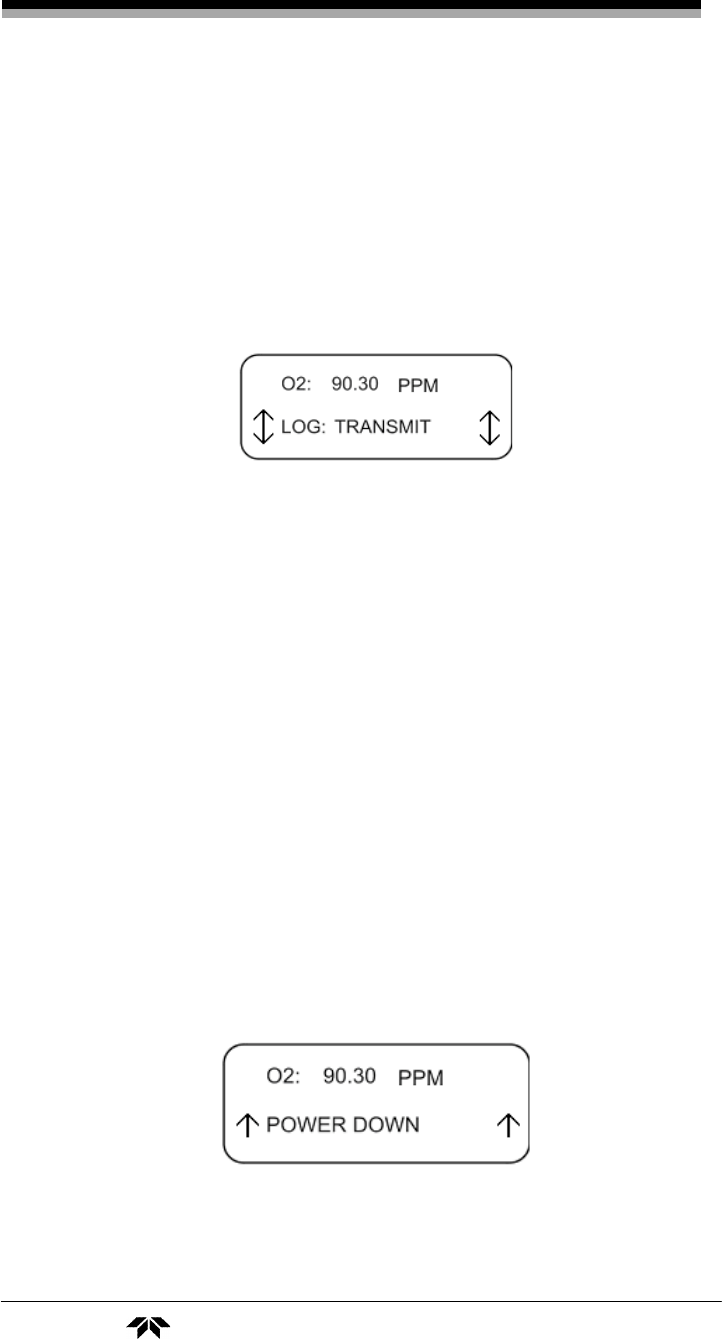
3.2.18 LOG TRANSMIT Screen
Data can be downloaded to a computer using the optional RS-232
port and cable attached to a PC. The RS-232 port accepts a standard data
cable with a DB-9 connector. The computer must be able to accept data
from a RS-232 source with the following characteristics:
9600 baud
8 bit data
no parity
Operation Model 3110
38 Teledyne Analytical Instruments
1 stop bit
no flow control
Refer to your computer manual for details on how to setup the
optional RS-232 communications port on your computer.
To download a data log:
1. Use the UP/DOWN keys to navigate to the LOG TRANSMIT
screen. Then press ENTER to enter the setup screen.
2. Press ENTER again to transmit the current data log.
Note: The data set will be transmitted each time you press the
ENTER key. Use the ESC key to exit the LOG TRANSMIT
menu.
3. Press ESC to exit out of the LOG TRANSMIT screen and go
to the home screen.
Note: The Date Log does not need to be stopped in order to
transmit the date.
3.2.19 POWER DOWN Screen
This screen is used to power off the instrument.
To turn the analyzer off:

Portable Trace Oxygen Analyzer Operation
Teledyne Analytical Instruments 39
1. Use the UP/DOWN keys to navigate to the POWER DOWN
screen. Then press ENTER.
2. Press ENTER again to turn the instrument OFF.
In a few seconds the analyzer will turn off.

Maintenance Model 3110
40 Teledyne Analytical Instruments
Maintenance & Troubleshooting
4.1 Routine Maintenance
Other than replacing the sensor and cell holder O-ring, there are no
user-serviceable components within the instrument housing. Routine
maintenance consists of wiping down the instrument case, cleaning the
screen and checking for leaks.
CAUTION: USING ABRASIVE CLEANSERS OR SOLVENTS WILL
DAMAGE THE SCREEN. USE ONLY A MILD
DETERGENT AND SOFT CLOTH WHEN REMOVING
DIRT OR GREASE MARKS FROM THE SCREEN.
When cleaning the instrument case, do not flood with water or use
harsh, abrasive or solvent cleansers. These cleansers will attack the LCD
lens material as well as eventually wear off the silk-screened legends.
4.2 Opening the Instrument Case
CAUTION: DEPENDING ON THE APPLICATION, IT MAY BE
NECESSARY TO PURGE THE INSTRUMENT THEN
REMOVE THE INSTRUMENT TO A NON-
HAZARDOUS AREA BEFORE OPENING THE
INSTRUMENT CASE.
To open the enclosure:
1. Loosen (counter-clockwise) the three (3) ¼-turn screwdriver-
type fasteners on the back of the outer enclosure.
2. Pull off the back section of the cover
4.3 Replacing the Battery
After many charge/recharge cycles of the battery, eventually the
Ni-Cd batteries will have to be replaced. Usually, when the instrument
requires more frequent charge cycles than before it is time to change the

Portable Trace Oxygen Analyzer Maintenance
Teledyne Analytical Instruments 41
batteries. Refer to the Spare Parts Listing in the Appendix for the correct
replacement battery.
Note: The batteries are not user serviceable. They can only be
replaced by a qualified technician.
4.4 Battery Power Supply Service
The Model 3110 is designed to be intrinsically safe, and is designed
for use only when not connected to the AC power line. TAI suggests
that an overnight recharge be performed every few days for continuous
use.
The low battery LED will begin to blink and the display will flicker
when the batteries are getting low. At this point, the batteries should be
recharged. To recharge the batteries, turn the instrument OFF (see
Section 3.2.19. Remove the instrument to a safe non-hazardous location.
Note: Depending on the application, purging may be required
before disconnecting the analyzer and moving it to a safe
location.
Plug the AC charger into a suitable 100-240 VAC 60 Hz power
source. Plug the other end of the charger cable into the port on the rear
of the instrument. Figure 4-1 shows the AC charger port on the rear
panel.
Note: During charging, the green battery charging indicator LED
will illuminate.
When recharging is completed, unplug the unit from the AC outlet
and disconnect the cable from the AC charger port.
Note: The analyzer cannot be turned on while the AC charger is
attached.
Maintenance Model 3110
42 Teledyne Analytical Instruments
Figure 4-1: Battery Charger Port on the Model 3110
4.5 Cell Replacement
The characteristics of the micro-fuel cell are similar to those of a
NiCad battery in that both provide an almost constant output through their
useful life, and then fall off sharply towards zero at the end. If the sample
being analyzed has a low oxygen concentration, cell failure will probably
be indicated by the inability to properly calibrate the analyzer. You will find
that very little span adjustment will be required to keep the analyzer
calibrated properly during the duration of a given cell’s useful life. If large
span adjustments are required to calibrate the instrument, or calibration
cannot be achieved within the range of the control, the cell should be
immediately replaced. Refer to section 4.4 before replacing the cell.
To offset the possibility of not having a replacement cell available
when it is needed, TAI recommends that a spare cell be purchased
shortly after the instrument is placed in service, and each time the cell is
replaced thereafter.
The spare cell should be carefully stored in an area that is not
subject to large variations in ambient temperature (75 °F nominal), and

Portable Trace Oxygen Analyzer Maintenance
Teledyne Analytical Instruments 43
in such a way as to obviate any possibility of incurring damage. Under
no circumstances should you disturb the integrity of the cell
package until the cell is to be actually used. If the cell package is
punctured and air permitted to enter, the cell will immediately start to
react to the presence of oxygen.
CAUTION: THE MICRO-FUEL CELL CONTAINS KOH SOLUTION,
WHICH IS CAUSTIC. SHOULD THE CELL RUPTURE,
A LEAK MAY CAUSE INJURY. PLEASE REFER TO
MATERIAL SAFETY DATA SHEET IN THE APPENDIX
TO LEARN ABOUT POTENTIAL HAZARDS AND
CORRECTIVE ACTION IN CASE OF ACCIDENT.
No tools are required to replace the cell in the instrument. Simply
unscrew (counterclockwise) the plug at the bottom of the analyzer and
the cell will drop out of the manifold cavity.
Remove the new cell from its package, and carefully remove the
shorting clip. Do not touch the silver-colored sensing surface of the cell,
as it is covered with a delicate Teflon membrane that can be ruptured in
handling.
Place the cell on the end of the cell holder cap so that the sensing
surface of the cell is in contact with the cap and the electrical contact
plate end of the cell is facing upwards. Insert the cell and cap in the
manifold cavity, and screw the cap back into place. Apply as much
pressure as you can with your fingers, but use no tools.
After the cell has been installed, purge the instrument with an inert
gas (or the sample), and then proceed as directed in section 3.1.1.
4.6 Cell Warranty
The Class B-2C, A-2C, B-2CXL and Insta Trace micro-fuel cells
used in the Model 3110 are warranted for six (6) months of service.
With regard to spare cells, service time starts when the cell is
removed from its oxygen barrier packaging. The customer should stock
only one spare cell per instrument at a time. Do not attempt to stockpile
spare cells.
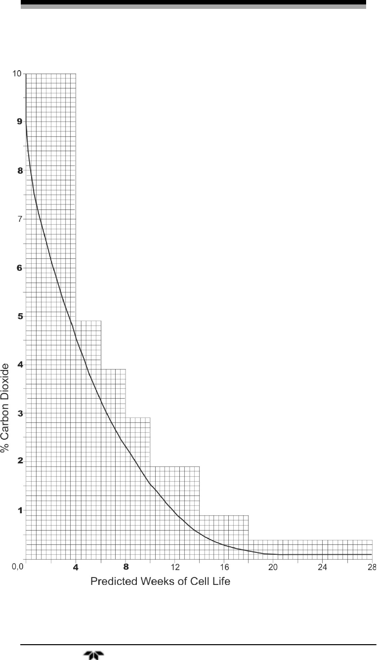
If the Model 3110 is used in trace analysis applications where CO2
is a major component in the sample, the A2C micro-fuel cell should be
used. At low CO2 concentrations (1,000 PPM or less) the standard B2C

Maintenance Model 3110
44 Teledyne Analytical Instruments
cell performance will not be affected. On the following page is a graph
showing the effects of CO2 on cell life.
WARNING: EVIDENCE OF DAMAGE DUE TO TAMPERING OR
MISHANDLING WILL RENDER THE CELL
WARRANTY NULL AND VOID.
4.7 Temperature Compensation
The micro-fuel cell has an inherent positive temperature coefficient.
Compensation is performed internally by the microprocessor and needs no
further adjustment.
Contact the factory if you suspect temperature related inaccuracies
during monitoring and are operating within the instrument’s temperature
operation range.
Portable Trace Oxygen Analyzer Maintenance
Teledyne Analytical Instruments 45
Effect of CO2 on B-2 Cell Life
1. This curve assumes continuous exposure.
2. Intermittent exposure will extend life. In
general, the CO2 effect is cumulative and
the average CO2 concentration should be
used to find the predicted cell life.
3. Cells can be used to make spot check
measurements of O2 in the presence of
high concentrations of CO2 (up to 50%
and more). Any sample containing CO2
should be purged as soon as a constant
reading is obtained.
4. Abnormally slow response and recovery
is characteristic of cells used as indicated
in notes 1, 2, and 3 above.
5. The reduction in cell life is primarily due
to a drop in output. Cell life will reduce
to a point where the instrument can no
longer be spanned. Instruments using B-2
cells in CO2 atmospheres should be
spanned at intervals of 10-20% of the
predicted cell life.
6. The CO2 effect on B-2 cells is
independent of the O2 level. Usage in
CO2 contributes significantly to cell life
reduction and thus affects cell warranty.
Figure 4-2: Effects of CO2 on B-2 Cell Life

Maintenance Model 3110
46 Teledyne Analytical Instruments
4.8 Leak Testing
WARNING: IF A LEAK IS SUSPECTED IN THE UNIT, DO NOT
ATTEMPT TO TIGHTEN THE QUICK DISCONNECT
FITTINGS. THE FITTINGS ARE POTTED IN EPOXY
AND TIGHTENING THEM WILL BREAK THE SEAL.
To check for leaks, TAI recommends one of the following
procedures:
Procedure I:
1. Purge the instrument to as low a value as possible. Use a
sensitive range for analysis for instance, 0-1% range. Take
note of the oxygen concentration.
2. Place the vent line in water and disconnect the sample.
3. Next, disconnect the vent line and use the same analysis
range. The reading should not increase above the level to
which you purged to.
Procedure II:
1. Purge the instrument with nitrogen at the sample port.
2. Using a flow rate of approximately 1 SCFH, note the reading
once it has stabilized (at least 24 hours on the 0-10 PPM
range).
3. Increase the flow rate from 1 SCFH to 2 SCFH.
4. Note how much the reading has changed after a few minutes.
5. Reduce the flow rate to 0.5 SCFH.
6. Note how much the reading has changed.
7. The reading should change by less than 10% of the original
value.

Portable Trace Oxygen Analyzer Maintenance
Teledyne Analytical Instruments 47
Intentionally left blank.

Appendix Model 3110
48 Teledyne Analytical Instruments
Appendix
A.1 Specifications
TAI Sales Order Number:
Instrument Serial Number:
Micro-fuel Cell Class: B-2, A-2C, B-2CXL, Insta Trans
Ranges of Analysis: 2 user defined ranges*
Accuracy: ±2% of scale or ±1 PPM (whichever is
greater) at constant temperature;
±5% of reading or ±1 PPM (whichever is
greater) over the operating temperature
range.
Operating Temp. Range: 0 °C to 40 °C (32 °F to 104 °F)
Sample Temp. Range: 0-40°C
Sample Flow rate: 0.5 – 2.5 SCFH
Recommended Span Gas: 80-90% of range most likely to be used
Signal Output: 0-1VDC
Dimensions: 10.9” x 6.2” x 5.2” deep
Weight: 4.38 lbs. (1.99kg.)
Power Requirements: 100-240 VAC 47-63H Charging Adapter
* In auto range mode only

Portable Trace Oxygen Analyzer Appendix
Teledyne Analytical Instruments 49
A.2 Spare Parts List
QTY P/N DESCRIPTION
1 O-165 Cell Cap O-Ring (Std.)
2 B27296 Battery (must be installed by a qualified
technition).
1 A761 Battery Charger, Universal
1 CP2487 2-pin 0-1 VDC Output Plug
1 A36289 Calibration Kit Std.
2 F1378 Fuse 200 mA(T)
1 A65476 Std. Cell Cap with O-Ring
* Micro Fuel Cell Options
1 C6689-B2C* Micro-Fuel Cell, Class B-2C
1 C6689-A2C Micro-Fuel Cell, Class A2C
1 C6689-B2C-XL Micro-Fuel Cell, Class B2C-XL
1 C71792-C-1-NY-1 Insta Trace Retrofit Kit (Std.)
1 C71792-C-13-NY-3 Insta Trace Retrofit Kit (XL)
1 C71792-C-7-NY-2 Insta Trace Retrofit Kit (O2)
A minimum charge of US$150.00 applies to spare parts orders.
IMPORTANT: Orders for replacement parts should include the model
number, serial number, and range of the analyzer for
which the parts are intended.
Orders should be sent to:
TELEDYNE ANALYTICAL INSTRUMENTS
16830 Chestnut Street
City of Industry, California 91748 USA
Phone: (626) 934-1500
FAX: (626) 934-1651
or your local representative
www.teledyne-ai.com | email: ask_tai@teledyne.com

Appendix Model 3110
50 Teledyne Analytical Instruments
Index
A2C cell, 43
AC adapter. See charge adapter
AC charger port, 41
accuracy, 14, 48
alarm, 29
enable/disable, 29
failsafe, 29
HI/LOW, 29
latching, 29, 31
resetting, 32
alarm setpoint, 29
analysis range, 10, 48
arrow, 25
atmospheric pressure application, 19
auto-ranging, 12, 32
B2C cell, 44
battery, 10, 17
battery recharging, 12
battery replacement, 40
blinking screen, 25
buttons, 12
calibrate
unable to, 42
calibration, 20
trace sensor, 21
calibration kit, 19
carbon monoxide, 13
caution sign, iv
cell holder cap, 43
cell manifold, 10
cell replacement, 43
cell storage, 42
cell warranty, 13, 43
changing an alarm setpoint, 29
changing ppm to %, 29
changing the date, 27
changing the range, 32
changing the time, 28
charge adapter, 10, 12
charge indicator, 17
charger adapter, 17
cleaning the instrument, 40
clock, 12
CO2 component, 43
combustible gas warning, ix
company address, 49
contact plate, 43
continuous operation, 18, 41
contrast, 12
copyright, ii
current date, 27
current time, 28
data logger, 27, 28, 36
data logging, 11
date & time setting, 11
DATE screen, 27
date stamping, 27
DB-9 connector, 37
dimensions, 48
display, 10, 12
downloading, 37
electrochemical transducer, 13
ENTER/ON key, 24
ESC key, 24, 25
Factory Mutual, 14
failsafe. See alarm
features, 11
filter, 35
FILTER screen, 35
filter setting, 14
flickering display, 18, 41
flow control valve, 19
flow rate, 14, 18, 22, 46
flow rate insensitivity, 13
flowmeter, 19
frequent charge cycles, 40
front panel, 24
front panel keys, 24
gas connection, 18
gas sampling, 19
hazardous environment, 10, 14
HI alarm, 31
HI-LO screen, 30
HOME screen, 27

Portable Trace Oxygen Analyzer Index
Teledyne Analytical Instruments 51
housing, 10, 14
hydrocarbons, 13
impedance, 14, 23
inaccurate analysis, 19
incrementing a value, 26
instrument position, 15
intrinsically safe, 10, 14, 41
leak testing, 46
LED, 12
LO alarm, 31
LOG INTV screen, 36
LOG RESET & START screen, 36
LOG TRANSMIT screen, 37, 38
low battery, 12, 41
low battery indicator, 18, 41
LTCH ALARM screen, 31
maintenance, 40
manual mode, 33
manuals, additional, v
menu, 26
micro-fuel cell, 13, 42, 44, 48
microprocessor, 10, 13
navigation arrows. See arrow
noise, 35
opening the housing, 40
operating temperature, 48
output
percent of range, 12
sensor, 13
signal, 48
voltage, 14, 22
oxygen concentration, 13
oxygen diffusion, 13
oxygen level, 10
plastic tubing, 19
positive pressure application, 18
power, 12, 48
POWER DOWN screen, 39
power off, 38
power on, 24
POWER ON screen, 27
pressure control, 18
pump, 19
purge, 20, 21, 43, 46
purge flow rate, 20
quick disconnect button, 19
quick disconnect fitting, 10, 13, 19
RAM, 11
range. See analysis range
RANGE 1 screen, 32
RANGE 2 screen, 32
RANGE screen, 33
rear panel, 18
rechargeable batteries. See battery
recharging batteries, 17
recharging the batteries, 41
recharging time, 17
record capacity, 36
regulator, 20
bleeding of, 21
relay, 30
reset data, 36
resolution, 10
RS-232, 12, 37
safety information, iv
sample flow rate. See
sample in port, 18
sample line, 22
sample temperature, 48
sampling interval, 36
saving changes, 25
screen sequence, 26
selecting values, 25
sensor installation
trace sensor, 20
serial number, iii
setup, 17
setup exit, 25
setup screen, 24
shorting clip, 43
shutoff valve, 10
signal conditioning, 13
signal output. See output
software version, 27
span calibration, 34
span gas, 20, 48
span gas concentration, 20, 34
SPAN screen, 34
span value, 34
SPAN VALUE screen, 34
spare cell, 42
spare cells, 13
spare parts, 49
STANDARD ALARM screen, 29
stockpiling cells, 43
sulfur dioxide, 13
technician symbol, iv
Teflon membrane, 43
temperature coefficient, 44
temperature compensation, 13, 44

Appendix Model 3110
52 Teledyne Analytical Instruments
throttle valve, 18
time format, 28
TIME screen, 28
time stamping, 28
trace analysis application, 19
trapped air, 20, 21
tube fittings, 19
UP/DOWN key, 24, 25
user interface, 12
vent line, 19, 22, 46
vent line restriction, 19
warning sign, iv
warranty, ii
warranty claim, 14
website address, v
weight, 48
wetted components, 19
zero, 13
zero gas, 20
