Teledyne Field Wizard 2101 Users Manual
2101 to the manual 06698b58-6ffc-40df-9d70-84b73a03bd8f
2015-02-03
: Teledyne Teledyne-Field-Wizard-2101-Users-Manual-464492 teledyne-field-wizard-2101-users-manual-464492 teledyne pdf
Open the PDF directly: View PDF ![]() .
.
Page Count: 76
- Foreword
- Table of Contents
- Section 1 Introduction
- Section 2 Preparation and Installation
- Section 3 Operation
- Section 4 Modbus Protocol
- Section 5 Maintenance
- Appendix A Replacement Parts
- Appendix B Accessories
- Appendix C Material Safety Data Sheets
- Compliance Statements
- Warranty
Foreword
This instruction manual is designed to help you gain a thorough understanding of the
operation of the equipment. Teledyne Isco recommends that you read this manual
completely before placing the equipment in service.
Although Teledyne Isco designs reliability into all equipment, there is always the possi-
bility of a malfunction. This manual may help in diagnosing and repairing the malfunc-
tion.
If the problem persists, call or e-mail the Teledyne Isco Technical Service Department
for assistance. Simple difficulties can often be diagnosed over the phone.
If it is necessary to return the equipment to the factory for service, please follow the
shipping instructions provided by the Customer Service Department, including the
use of the Return Authorization Number specified. Be sure to include a note
describing the malfunction. This will aid in the prompt repair and return of the
equipment.
Teledyne Isco welcomes suggestions that would improve the information presented in
this manual or enhance the operation of the equipment itself.
Teledyne Isco is continually improving its products and reserves the right to
change product specifications, replacement parts, schematics, and instruc-
tions without notice.
Contact Information
Customer Service
Phone: (800) 228-4373 (USA, Canada, Mexico)
(402) 464-0231 (Outside North America)
Fax: (402) 465-3022
Email: IscoCSR@teledyne.com
Technical Service
Phone: (800) 775-2965 (Analytical)
(800) 228-4373 (Samplers and Flow Meters)
Email: IscoService@teledyne.com
Return equipment to: 4700 Superior Street, Lincoln, NE 68504-1398
Other Correspondence
Mail to: P.O. Box 82531, Lincoln, NE 68501-2531
Email: IscoInfo@teledyne.com
Web site: www.isco.com
Revised September 15, 2005

iii
2101 Field Wizard
Table of Contents
Section 1 Introduction
1.1 Introduction. . . . . . . . . . . . . . . . . . . . . . . . . . . . . . . . . . . . . . . . . . . . . . . . . . . . . . . . 1-1
1.2 Product Description. . . . . . . . . . . . . . . . . . . . . . . . . . . . . . . . . . . . . . . . . . . . . . . . . . 1-1
1.3 Identifying Module Components . . . . . . . . . . . . . . . . . . . . . . . . . . . . . . . . . . . . . . . 1-2
1.4 Safety Symbols and Hazard Alerts . . . . . . . . . . . . . . . . . . . . . . . . . . . . . . . . . . . . . 1-6
1.5 Technical Service. . . . . . . . . . . . . . . . . . . . . . . . . . . . . . . . . . . . . . . . . . . . . . . . . . . . 1-6
Section 2 Preparation and Installation
2.1 Unpacking Instructions . . . . . . . . . . . . . . . . . . . . . . . . . . . . . . . . . . . . . . . . . . . . . . 2-1
2.2 Safety . . . . . . . . . . . . . . . . . . . . . . . . . . . . . . . . . . . . . . . . . . . . . . . . . . . . . . . . . . . . . 2-2
2.3 Connecting To Flowlink . . . . . . . . . . . . . . . . . . . . . . . . . . . . . . . . . . . . . . . . . . . . . . 2-2
2.4 Connecting To a Site . . . . . . . . . . . . . . . . . . . . . . . . . . . . . . . . . . . . . . . . . . . . . . . . . 2-4
2.4.1 Latches - Locking and Unlocking . . . . . . . . . . . . . . . . . . . . . . . . . . . . . . . . . 2-5
2.4.2 Communication Connectors . . . . . . . . . . . . . . . . . . . . . . . . . . . . . . . . . . . . . 2-7
2.4.3 Stacking Modules . . . . . . . . . . . . . . . . . . . . . . . . . . . . . . . . . . . . . . . . . . . . . . 2-7
Section 3 Operation
3.1 Introduction. . . . . . . . . . . . . . . . . . . . . . . . . . . . . . . . . . . . . . . . . . . . . . . . . . . . . . . . 3-1
3.2 Field Wizard Keypad. . . . . . . . . . . . . . . . . . . . . . . . . . . . . . . . . . . . . . . . . . . . . . . . . 3-1
3.3 Flowlink Connection . . . . . . . . . . . . . . . . . . . . . . . . . . . . . . . . . . . . . . . . . . . . . . . . . 3-3
3.3.1 Connecting To a PC . . . . . . . . . . . . . . . . . . . . . . . . . . . . . . . . . . . . . . . . . . . . 3-3
3.3.2 Communication Resolution . . . . . . . . . . . . . . . . . . . . . . . . . . . . . . . . . . . . . . 3-5
3.3.3 Site and Module Name . . . . . . . . . . . . . . . . . . . . . . . . . . . . . . . . . . . . . . . . . 3-5
3.4 Connecting to a Site . . . . . . . . . . . . . . . . . . . . . . . . . . . . . . . . . . . . . . . . . . . . . . . . . 3-6
3.5 Site Time Synchronization . . . . . . . . . . . . . . . . . . . . . . . . . . . . . . . . . . . . . . . . . . . . 3-7
3.6 Data Retrieval Mode . . . . . . . . . . . . . . . . . . . . . . . . . . . . . . . . . . . . . . . . . . . . . . . . . 3-7
3.6.1 Retrieve Data Display . . . . . . . . . . . . . . . . . . . . . . . . . . . . . . . . . . . . . . . . . . 3-9
3.6.2 Data Retrieval Log Display . . . . . . . . . . . . . . . . . . . . . . . . . . . . . . . . . . . . . 3-11
3.6.3 Site Setup Display . . . . . . . . . . . . . . . . . . . . . . . . . . . . . . . . . . . . . . . . . . . . 3-12
3.6.4 Data Display . . . . . . . . . . . . . . . . . . . . . . . . . . . . . . . . . . . . . . . . . . . . . . . . 3-15
3.6.5 Site Information Display . . . . . . . . . . . . . . . . . . . . . . . . . . . . . . . . . . . . . . . 3-16
3.7 Standalone Mode. . . . . . . . . . . . . . . . . . . . . . . . . . . . . . . . . . . . . . . . . . . . . . . . . . . 3-16
3.7.1 Standalone Information Display . . . . . . . . . . . . . . . . . . . . . . . . . . . . . . . . . 3-17
3.8 PC Data Synchronization Mode . . . . . . . . . . . . . . . . . . . . . . . . . . . . . . . . . . . . . . . 3-17
Section 4 Modbus Protocol
4.1 Introduction. . . . . . . . . . . . . . . . . . . . . . . . . . . . . . . . . . . . . . . . . . . . . . . . . . . . . . . . 4-1
4.2 Operation . . . . . . . . . . . . . . . . . . . . . . . . . . . . . . . . . . . . . . . . . . . . . . . . . . . . . . . . . . 4-1
4.2.1 Establishing Communication . . . . . . . . . . . . . . . . . . . . . . . . . . . . . . . . . . . . 4-2
4.2.2 Module Addressing . . . . . . . . . . . . . . . . . . . . . . . . . . . . . . . . . . . . . . . . . . . . 4-2
4.3 Configurations. . . . . . . . . . . . . . . . . . . . . . . . . . . . . . . . . . . . . . . . . . . . . . . . . . . . . . 4-3
4.4 Glossary of Terms . . . . . . . . . . . . . . . . . . . . . . . . . . . . . . . . . . . . . . . . . . . . . . . . . . . 4-4
4.5 Common Acronyms . . . . . . . . . . . . . . . . . . . . . . . . . . . . . . . . . . . . . . . . . . . . . . . . . . 4-5
4.6 Register Specifications . . . . . . . . . . . . . . . . . . . . . . . . . . . . . . . . . . . . . . . . . . . . . . . 4-6

2101 Field Wizard
Table of Contents
iv
Section 5 Maintenance
5.1 Maintenance Overview . . . . . . . . . . . . . . . . . . . . . . . . . . . . . . . . . . . . . . . . . . . . . . . 5-1
5.1.1 Cleaning . . . . . . . . . . . . . . . . . . . . . . . . . . . . . . . . . . . . . . . . . . . . . . . . . . . . . 5-1
5.2 Maintenance Kit . . . . . . . . . . . . . . . . . . . . . . . . . . . . . . . . . . . . . . . . . . . . . . . . . . . . 5-1
5.3 Desiccant . . . . . . . . . . . . . . . . . . . . . . . . . . . . . . . . . . . . . . . . . . . . . . . . . . . . . . . . . . 5-2
5.3.1 Replacing the Desiccant: 2101 . . . . . . . . . . . . . . . . . . . . . . . . . . . . . . . . . . . 5-2
5.3.2 Reactivating the Desiccant . . . . . . . . . . . . . . . . . . . . . . . . . . . . . . . . . . . . . . 5-2
5.4 Hydrophobic Filter . . . . . . . . . . . . . . . . . . . . . . . . . . . . . . . . . . . . . . . . . . . . . . . . . . 5-3
5.5 How to Obtain Service . . . . . . . . . . . . . . . . . . . . . . . . . . . . . . . . . . . . . . . . . . . . . . . 5-3
Appendix A Replacement Parts
A.1 Replacement Parts . . . . . . . . . . . . . . . . . . . . . . . . . . . . . . . . . . . . . . . . . . . . . . . . . . A-1
Appendix B Accessories
B.1 How to Order. . . . . . . . . . . . . . . . . . . . . . . . . . . . . . . . . . . . . . . . . . . . . . . . . . . . . . . B-1
B.2 General Accessories . . . . . . . . . . . . . . . . . . . . . . . . . . . . . . . . . . . . . . . . . . . . . . . . . B-1
Appendix C Material Safety Data Sheets
C.1 Overview . . . . . . . . . . . . . . . . . . . . . . . . . . . . . . . . . . . . . . . . . . . . . . . . . . . . . . . . . . C-1
List of Figures
1-1 Field Wizard Keypad and Display . . . . . . . . . . . . . . . . . . . . . . . . . . . . . . . . . . . . . . 1-2
1-2 Field Wizard Components - Side View . . . . . . . . . . . . . . . . . . . . . . . . . . . . . . . . . . 1-3
1-3 Field Wizard Components - Bottom View . . . . . . . . . . . . . . . . . . . . . . . . . . . . . . . . 1-4
1-4 Model 2101 Field Wizard Connector Pins . . . . . . . . . . . . . . . . . . . . . . . . . . . . . . . . 1-5
2-1 Connecting the AC Adapter to the Field Wizard . . . . . . . . . . . . . . . . . . . . . . . . . . 2-3
2-2 Connecting the Communication Cable to the Field Wizard . . . . . . . . . . . . . . . . . 2-3
2-3 Flowlink Site Info Screen . . . . . . . . . . . . . . . . . . . . . . . . . . . . . . . . . . . . . . . . . . . . . 2-4
2-4 Data Retrieval Mode Main Display . . . . . . . . . . . . . . . . . . . . . . . . . . . . . . . . . . . . 2-10
3-1 Field Wizard Keypad and Display . . . . . . . . . . . . . . . . . . . . . . . . . . . . . . . . . . . . . . 3-2
3-2 Flowlink Site Info Screen . . . . . . . . . . . . . . . . . . . . . . . . . . . . . . . . . . . . . . . . . . . . . 3-4
3-3 Field Wizard Connected to a 2150 Site . . . . . . . . . . . . . . . . . . . . . . . . . . . . . . . . . . 3-6
3-4 Synchronize Time Display . . . . . . . . . . . . . . . . . . . . . . . . . . . . . . . . . . . . . . . . . . . . 3-7
3-5 Data Retrieval Mode Main Display . . . . . . . . . . . . . . . . . . . . . . . . . . . . . . . . . . . . . 3-8
3-6 Retrieve Data Display . . . . . . . . . . . . . . . . . . . . . . . . . . . . . . . . . . . . . . . . . . . . . . . 3-9
3-7 Data Retrieval Status Display . . . . . . . . . . . . . . . . . . . . . . . . . . . . . . . . . . . . . . . . . 3-9
3-8 Retrieve # Days Display . . . . . . . . . . . . . . . . . . . . . . . . . . . . . . . . . . . . . . . . . . . . . 3-10
3-9 Log Display . . . . . . . . . . . . . . . . . . . . . . . . . . . . . . . . . . . . . . . . . . . . . . . . . . . . . . . 3-11
3-10 Data Log Details Display . . . . . . . . . . . . . . . . . . . . . . . . . . . . . . . . . . . . . . . . . . 3-12
3-11 Field Wizard Site Setup Display . . . . . . . . . . . . . . . . . . . . . . . . . . . . . . . . . . . . 3-13
3-12 Field Wizard Backlight Mode Settings . . . . . . . . . . . . . . . . . . . . . . . . . . . . . . . 3-13
3-13 Site Setup Display . . . . . . . . . . . . . . . . . . . . . . . . . . . . . . . . . . . . . . . . . . . . . . . . 3-14
3-14 Level Calibration Display . . . . . . . . . . . . . . . . . . . . . . . . . . . . . . . . . . . . . . . . . . 3-14
3-15 Sensor Diagnostics Display . . . . . . . . . . . . . . . . . . . . . . . . . . . . . . . . . . . . . . . . . 3-15
3-16 Data Display . . . . . . . . . . . . . . . . . . . . . . . . . . . . . . . . . . . . . . . . . . . . . . . . . . . . 3-15
3-17 Site Information Display . . . . . . . . . . . . . . . . . . . . . . . . . . . . . . . . . . . . . . . . . . . 3-16
3-18 Standalone Mode Main Display . . . . . . . . . . . . . . . . . . . . . . . . . . . . . . . . . . . . . 3-16
3-19 Standalone Information Display . . . . . . . . . . . . . . . . . . . . . . . . . . . . . . . . . . . . 3-17
3-20 PC Data Synchronization Mode Display . . . . . . . . . . . . . . . . . . . . . . . . . . . . . . 3-17
4-1 Configuration Example (Direct Connection Shown) . . . . . . . . . . . . . . . . . . . . . . . 4-3

2101 Field Wizard
Table of Contents
v
List of Tables
1-1 Field Wizard Components - Side View . . . . . . . . . . . . . . . . . . . . . . . . . . . . . . . . . . 1-3
1-2 Field Wizard Components - Bottom View . . . . . . . . . . . . . . . . . . . . . . . . . . . . . . . . 1-4
1-3 2101 Field Wizard Technical Specifications . . . . . . . . . . . . . . . . . . . . . . . . . . . . . . 1-5
1-4 Field Wizard Connector Pins . . . . . . . . . . . . . . . . . . . . . . . . . . . . . . . . . . . . . . . . . . 1-5
4-1 Modbus ASCII Address 1 Register Definitions . . . . . . . . . . . . . . . . . . . . . . . . . . . . 4-6
4-2 Modbus ASCII Address 2-(N+1) Register Definitions . . . . . . . . . . . . . . . . . . . . . . 4-7
4-3 Measurement Parameters by Model Number* . . . . . . . . . . . . . . . . . . . . . . . . . . . . 4-9

2101 Field Wizard
Table of Contents
vi

1-1
2101 Field Wizard
Section 1 Introduction
1.1 Introduction This instruction manual is designed to help you gain a thorough
understanding of the operation of the 2101 Field Wizard.
Teledyne Isco recommends that you read this manual completely
before placing the equipment into service.
1.2 Product Description The 2101 Field Wizard is a portable data interrogation unit
designed to collect data from Isco’s 2100 Series flow modules,
which measure parameters of open channel flow streams. It then
transfers that data to Isco’s Flowlink 4 for Windows software.
The Field Wizard also serves as a local display and keypad for a
2100 Series site. The eight-line by forty-character graphics
display provides quick access to current readings and diagnostic
information, and allows for calibration of level measurements.
The Field Wizard stacks on top of a 2100 Series module, using
the same locking mechanism that connects the 2100 Series
modules to each other. Because modules have unique assigned
names, the Field Wizard can retrieve data from multiple modules
and can be easily moved from site to site.
The Field Wizard uses flash memory, which retains data without
the concern of power failures or aging backup batteries. The data
storage memory can hold up to fourteen days worth of data
recorded at fifteen minute intervals from twenty different
modules.
All enclosures are rated NEMA 4X, 6P and IP68. The perma-
nently sealed enclosures are designed to meet the environmental
demands of many sewer flow monitoring applications. All connec-
tions between modules, sensors, and communication cables "lock"
in place. The locking mechanisms strongly secure the compo-
nents and ensure a watertight seal.
Its rugged, compact design and simplicity of use make the Field
Wizard a convenient alternative to using a laptop computer for
displaying site data or transferring data from the 2100 Series
module to a personal computer.
2101 Field Wizard
Section 1 Introduction
1-2
1.3 Identifying Module
Components
Figures 1-2 through 1-3 identify the key components of the 2101
Field Wizard.
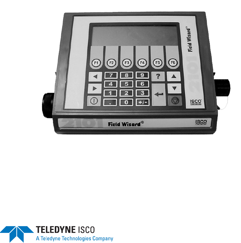
The Field Wizard is operated from the top panel, which contains
a keypad and liquid crystal display. The keypad, shown in Figure
1-1, includes 26 keys that are used to program and operate the
Field Wizard.
Figure 1-1 Field Wizard Keypad and Display
The keypad contains six software configured function keys (soft
keys) that are used to make selections and navigate through
menus. Their specific functions will depend upon what operation
you are performing, and will be shown in the display window.
The four arrow keys are used for navigation within menus and
displays. The Enter key is used to complete data entry,
acknowledge prompts, and signal the start of certain operations.
Numeric keys are active when numeric data is to be entered.
Press the Help key to obtain context sensitive help.
The Power key places the unit into an ultra low power state,
during which the display window will be blank.
The Escape key is not currently used. During some operations,
one of the function keys will serve as a Cancel key.
The unit is equipped with an audible beeper. The beeper
acknowledges key presses, and signals errors when incorrect
entries are made.
DWG 69-2003-143
Arrow Keys
Help Key
2101 Field Wizard
Section 1 Introduction
1-3
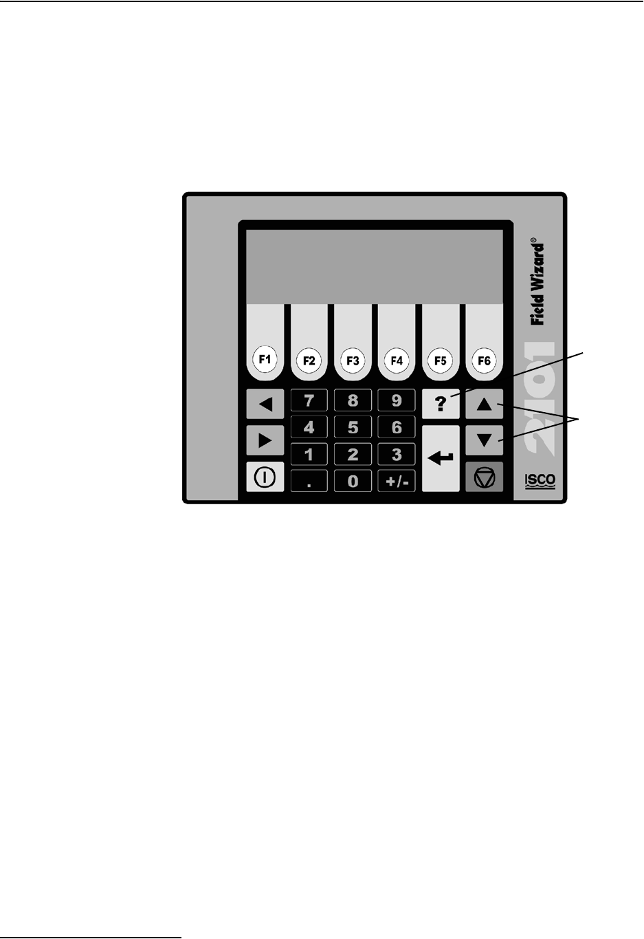
Figure 1-2 Field Wizard Components - Side View
1
2
3
Table 1-1 Field Wizard Components - Side View
Item No. Name Description
1 Communication Connector This port is used to connect to a personal computer running
Flowlink software.
2 Connector Cap Insert into the communication connector when it is not in use to
protect the connector from damage.
3 Latch Release Push in to unlock the module from a stack.
2101 Field Wizard
Section 1 Introduction
1-4
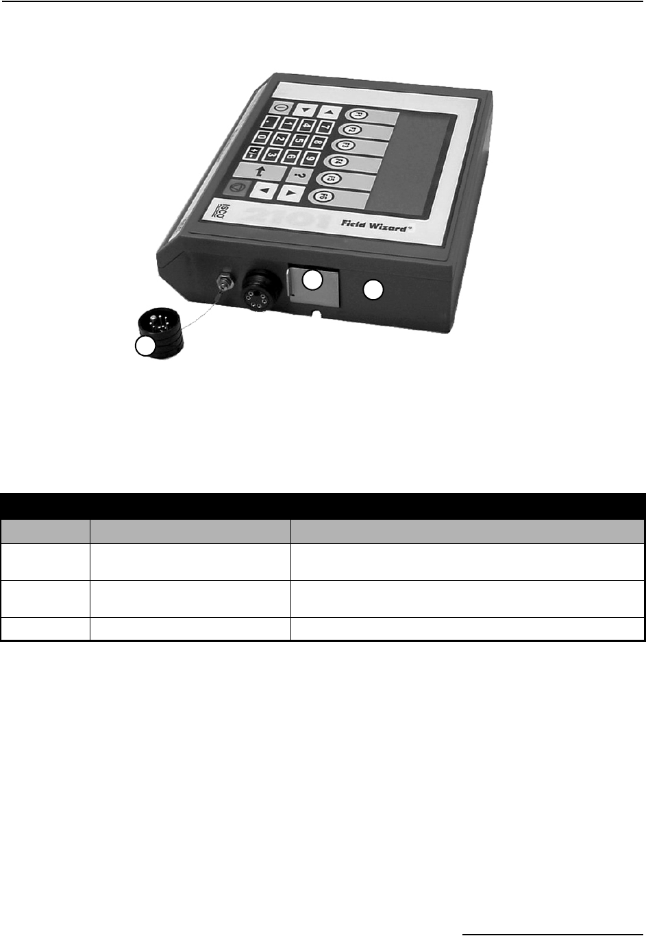
Figure 1-3 Field Wizard Components - Bottom View
12
3
4
5
Table 1-2 Field Wizard Components - Bottom View
Item No. Name Description
1 Communication Connector This connects the Field Wizard to the 2100 Series module and is used to
transfer data.
2 Connector Cap Insert into the communication connector when not in use to protect the
connector from moisture damage. When the connector is in use, store
the connector cap in the cap holder.
3 Cap Holder Stores the connector cap when the communication connector is in use.
4 Desiccant Cartridge and
Hydrophobic Filter
Prevents moisture from entering the unit.
5 Latch Push in to lock the module in a stack.
2101 Field Wizard
Section 1 Introduction
1-5
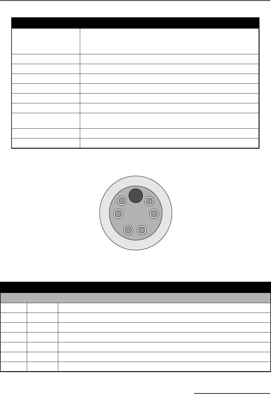
Figure 1-4 Model 2101 Field Wizard Connector Pins
Table 1-3 2101 Field Wizard Technical Specifications
Dimensions Length = 11.3 inches (28.70 cm)
Width = 7.5 inches (19.05 cm)
Height = 2.9 inches (7.37 cm)
Weight 2 lbs. (.9 Kg)
Material HIgh-impact molded polystyrene
Enclosure NEMA 4X, 6P, IP68
Power 6.6 to 16.6 VDC, 110 mA typical at 12 VDC, 1 mA standby
Operating Temperature -4° to 140°F (-20° to 60°C)
Storage Temperature -40° to 140°F (-40° to 60°C)
Setup and Data Retrieval Serial connection to IBM PC or compatible computer with Isco Flowlink soft-
ware version 4.12 or higher
Baud Rate 38,400
File System Memory Capacity The Field Wizard is capable of storing a minimum of 1.5 Mbytes of data.
A
B
C
D
E
F
G
Table 1-4 Field Wizard Connector Pins
Pin Name Description
A LONA Neuron differential transceiver Data A
B LONB Neuron differential transceiver Data B
C VIN+ Positive power supply voltage input (+12 VDC nominal)
D VIN– Negative power supply voltage input (0 VDC nominal)
E RCVUP PC data receiver inverted input
F XMTUP PC data transmit inverted output
G Key Aligns connector pins

2101 Field Wizard
Section 1 Introduction
1-6
1.4 Safety Symbols and
Hazard Alerts
This icon identifies a general hazard and is accompanied
with details about the hazard. The instruction manual
identifies the hazardous condition and any steps nec-
essary to correct the condition. The manual presents this infor-
mation in one of two ways:
CAUTION
Cautions identify a potential hazard, which if not avoided, may
result in minor or moderate injury. This category can also warn
you of unsafe practices, or conditions that may cause property
damage.
WARNING
Warnings indicate potentially hazardous conditions. If you
do not avoid these risks, they could cause you death or
serious injury.
1.5 Technical Service Although Teledyne Isco designs reliability into all of its
equipment, there is always the possibility of a malfunction
occurring. You can use this manual to help in diagnosing and
repairing any malfunctions. If the malfunction persists, call or
write the Teledyne Isco Technical Service Department for assis-
tance:
Teledyne Isco Inc.
Technical Service Department
P.O. Box 82531
Lincoln, NE 68501
800-228-4373 or 402-464-0231
FAX: 402-465-3001
E-MAIL: service@isco.com
Simple difficulties can often be diagnosed over the phone. If it is
necessary to return the equipment to the factory for service,
please follow the shipping instructions provided by the Technical
Service Department, including the use of the Return Authori-
zation Number specified. Be sure to include a note describing the
malfunction. This will aid in the prompt repair and return of the
equipment.

2-1
2101 Field Wizard
Section 2 Preparation and Installation
2.1 Unpacking
Instructions
When the system arrives, inspect the contents for any damage. If
there is damage, contact the delivery company and Teledyne Isco
(or its agent) immediately.
WARNING
If there is any evidence that any items may have been
damaged in shipping, do not attempt to install the unit.
Please contact Teledyne Isco (or its agent) for advice.
When you unpack the system, check the items against the
packing list. If any parts are missing, contact the delivery
company and Teledyne Isco’s Customer Service Department.
When you report missing part(s), please indicate them by part
number. In addition to the main packing list, there may be other
packing lists for various sub-components.
It is recommended that you retain the shipping cartons as they
can be used to ship the unit in the event that it is necessary to
transport the system.
Please complete the registration card and return it to Teledyne
Isco, Inc.
Teledyne Isco, Inc.
Customer Service Dept.
P.O. Box 82531
Lincoln, NE 68501 USA
Phone: (800) 228-4373
Outside USA & Canada call:
(402) 464-0231
FAX: (402) 465-3022
E-mail: info@isco.com

2101 Field Wizard
Section 2 Preparation and Installation
2-2
2.2 Safety
WARNING
Avoid hazardous practices! If you use these instruments in
any way not specified in this manual, the protection
provided by the instruments may be impaired; this will
increase your risk of injury.
WARNING
The installation and use of this product may subject you
to hazardous working conditions that can cause you
serious or fatal injuries. Take any necessary precautions
before entering a worksite. Install and operate this product
in accordance with all applicable safety and health
regulations, and local ordinances.
The 2100 Series components are often installed in confined
spaces. Some examples of confined spaces include manholes,
pipelines, digesters, and storage tanks. These spaces may become
hazardous environments that can prove fatal for those unpre-
pared. These spaces are governed by OSHA 1910.146 and require
a permit before entering.
2.3 Connecting To
Flowlink
Before you use your Field Wizard in the field to collect data, you
need to synchronize it to Isco’s Flowlink software on a personal
computer (PC).
Use the following instructions to connect to Flowlink for the first
time. More detailed information about transferring data to
Flowlink can be found in Section 3.3.
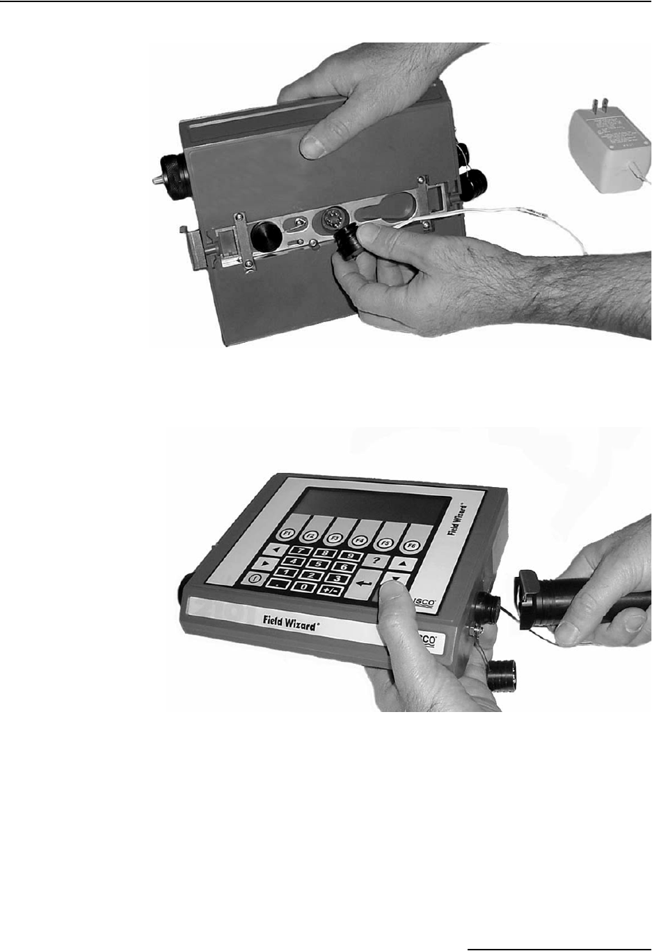
Use Isco’s communication cable P/N 60-2004-046 and AC
Adapter (P/N 60-2004-057) to connect the Field Wizard to a PC,
as shown in Figures 2-1 and 2-2.
Uncap the communication connector on the underside of the
Field Wizard, and store the connector cap in its holder. Then plug
the AC Adapter into the communication connector, as shown in
Figure 2-1. Plug the other end of the AC Adapter into a grounded
electrical outlet.
2101 Field Wizard
Section 2 Preparation and Installation
2-3
Figure 2-1 Connecting the AC Adapter to the Field Wizard
Figure 2-2 Connecting the Communication Cable to the Field Wizard
Uncap the communication connector on the right side of the Field
Wizard and attach the Communications Cable, as shown in
Figure 2-2. Connect the other end of the Communications Cable
to a serial COM port on the PC.
As a default Flowlink setting, the Quick Connect dialog box
opens when you start Flowlink. (If it is not open, click the Quick
Connect icon or select File, Quick Connect.)
2101 Field Wizard
Section 2 Preparation and Installation
2-4
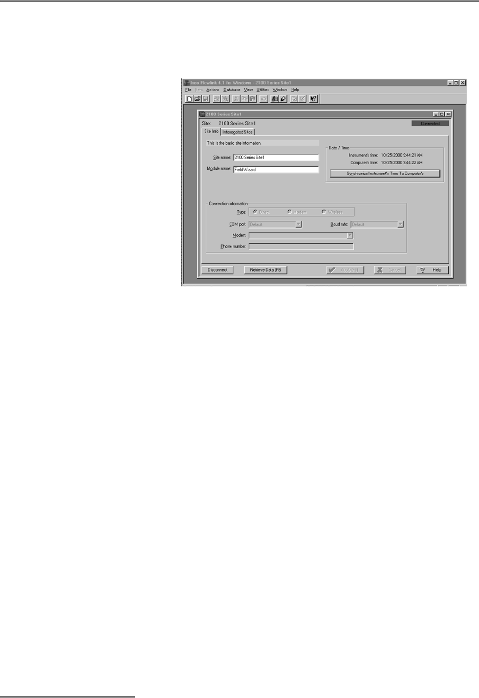
Click the large Field Wizard button to connect. Flowlink will
read the 2101 system information and try to match it with an
existing site in the open database. It will then display the Site
Info tab of the Site Window (Figure 2-3).
Figure 2-3 Flowlink Site Info Screen
Complete the following steps:
1. Click the Synchronize Instrument’s Time to Com-
puter’s button to synchronize the Field Wizard’s time to
that of your PC. (If you are using multiple PCs, select just
one PC to synchronize with.)
2. The Field Wizard is shipped with default site and module
names. Use the Site Name and Module Name fields if
you want to provide more descriptive names. Select Apply
(F9) to write that information to the instrument.
3. Although data has not yet been collected, you need to click
Retrieve Data (F8). This transfers a file containing site
interrogation times from Flowlink to the Field Wizard.
With this information, the Field Wizard will know when
data was last retrieved from your site(s). When brought to
a site, the Field Wizard will then retrieve only the neces-
sary data.
4. Select Disconnect to end your PC session and disconnect
the Field Wizard.
2.4 Connecting To a Site Once you have connected the Field Wizard to Flowlink and set up
the initial configuration, you can connect the Field Wizard to a
site and retrieve data.
The Field Wizard module connects to the top of a 2100 Series
stack, which may contain multiple modules. The steps shown in
Sections 2.4.1 - 2.4.3 illustrate how to operate latches and con-
nectors and connect the Field Wizard to the site.
2101 Field Wizard
Section 2 Preparation and Installation
2-5
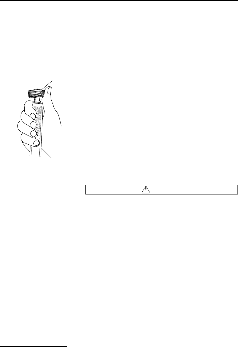
2.4.1 Latches - Locking and
Unlocking
Latches must be operated to stack and unstack the modules in a
Series 2100 stack. The mechanisms are the same for the Field
Wizard and other 2100 Series modules. Take a moment to famil-
iarize yourself with operating the latches. The latch is operated
by pushing on one of the sides — the right side to unlock, and the
left side to lock.
CAUTION
The latch can be damaged by applying too much force. Never
press on both sides at the same time. Do not force the latch if it
is obstructed. While some degree of pressure must be applied
to slide the latch, the ends of the latches should never bend
more than 1/8".
L’attache peut-être endommagée en la forçant. Ne jamais
presser simultanément des deux côtés à la fois. Ne pas forcer
en cas de résistance. Ne jamais tordre les extrémités des
attaches de plus de 3 mm.
Figure 2-4 shows how to unlock the latch. You must unlock the
latch to place the module on top of a stack. Otherwise, the latch
is normally locked.
Figure 2-5 shows how to lock the latch.
Note
Latches will “click” when they are fully locked and unlocked.

2101 Field Wizard
Section 2 Preparation and Installation
2-6
Push
Figure 2-1:
Unlocking the latch
Locate the latch release on the
right side of the module. Push in
to slide the latch toward the left of
the module.
Push
Figure 2-2:
Locking the latch
Locate the latch extending from
the left side of the module. Push
in to slide the latch toward the
right of the module.
2101 Field Wizard
Section 2 Preparation and Installation
2-7
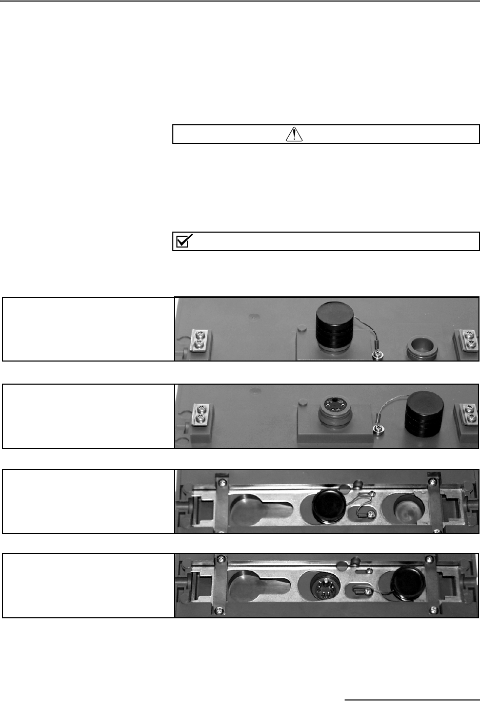
2.4.2 Communication
Connectors
Connecting the Field Wizard module involves uncapping and
capping communication connectors. When a communication con-
nector is not in use, the connector should always be capped
(Figures 2-6 and 2-8). The cap will seal the connector to prevent
corrosion, and will improve communications.
When a communication connector is in use, store the cap on the
holder next to the connector (Figures 2-7 and 2-9). The communi-
cation connector will be sealed by its mating connector.
CAUTION
Caps PUSH ON and PULL OFF. Do not rotate the caps to
remove them from the connectors.
Capuchons POUSSER et TIRER. Ne pas tourner les
capuchons pour les enlever des prises.
Note
For modules to correctly stack and lock together, protective
caps between the modules must be stored on the holders.
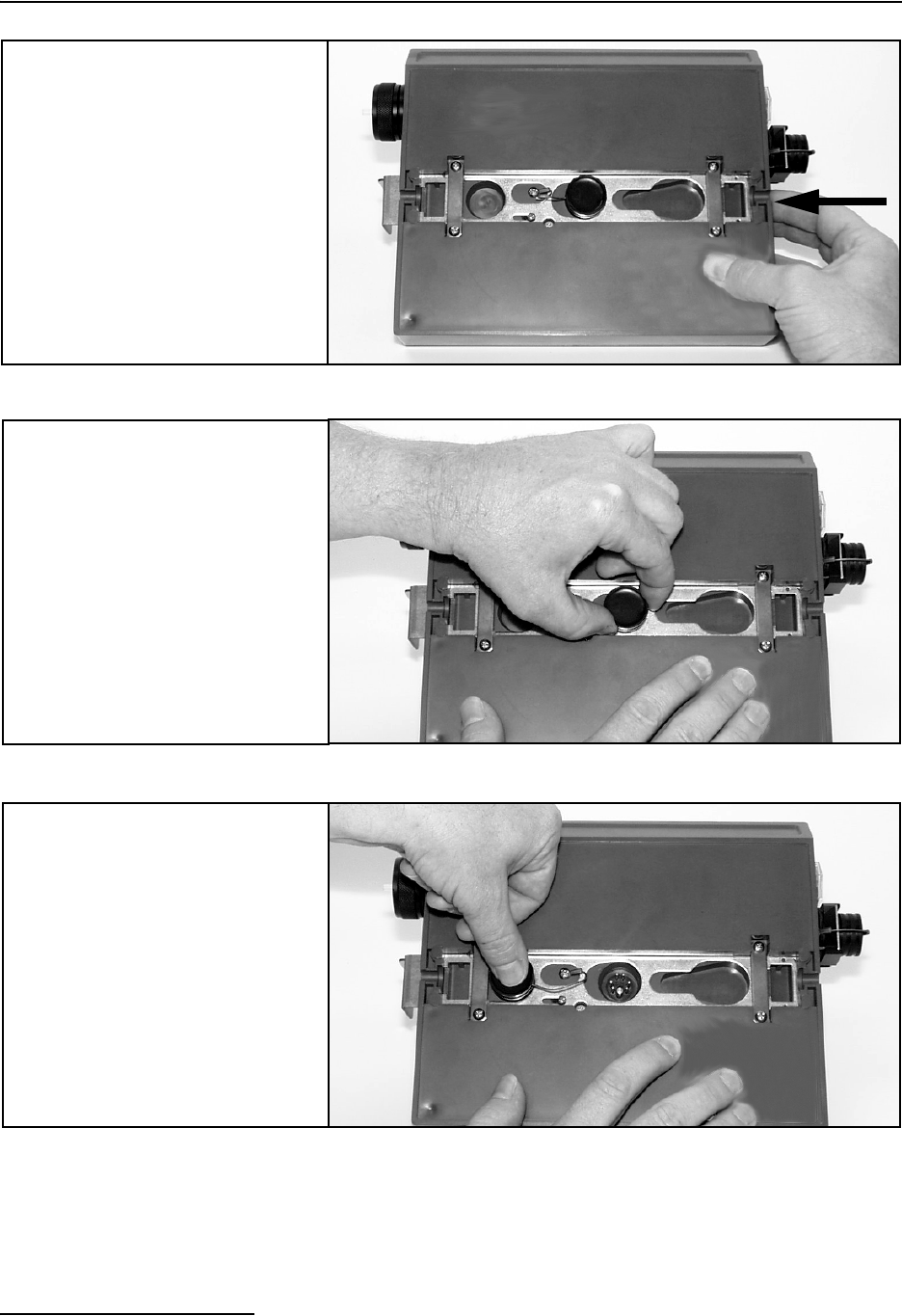
2.4.3 Stacking Modules To stack a Field Wizard Module on a 2100 Series Module, follow
the instructions in Figures 2-10 through 2-17.
Figure 2-3:
2100 Series Module’s Upper
Connector - Capped
Figure 2-4:
2100 Series Module’s Upper
Connector - Uncapped
Figure 2-5:
Field Wizard’s Lower
Connector - Capped
Figure 2-6:
Field Wizard’s Lower
Connector - Uncapped
2101 Field Wizard
Section 2 Preparation and Installation
2-8
Figure 2-7:
Field Wizard module -
unlock the latch
Unlock the latch to release the
lower cap.
Figure 2-8:
Field Wizard module -
uncap the connector
Pull the cap off of the connector.
Figure 2-9:
Field Wizard module -
push cap into holder
Push the cap into the holder.
2101 Field Wizard
Section 2 Preparation and Installation
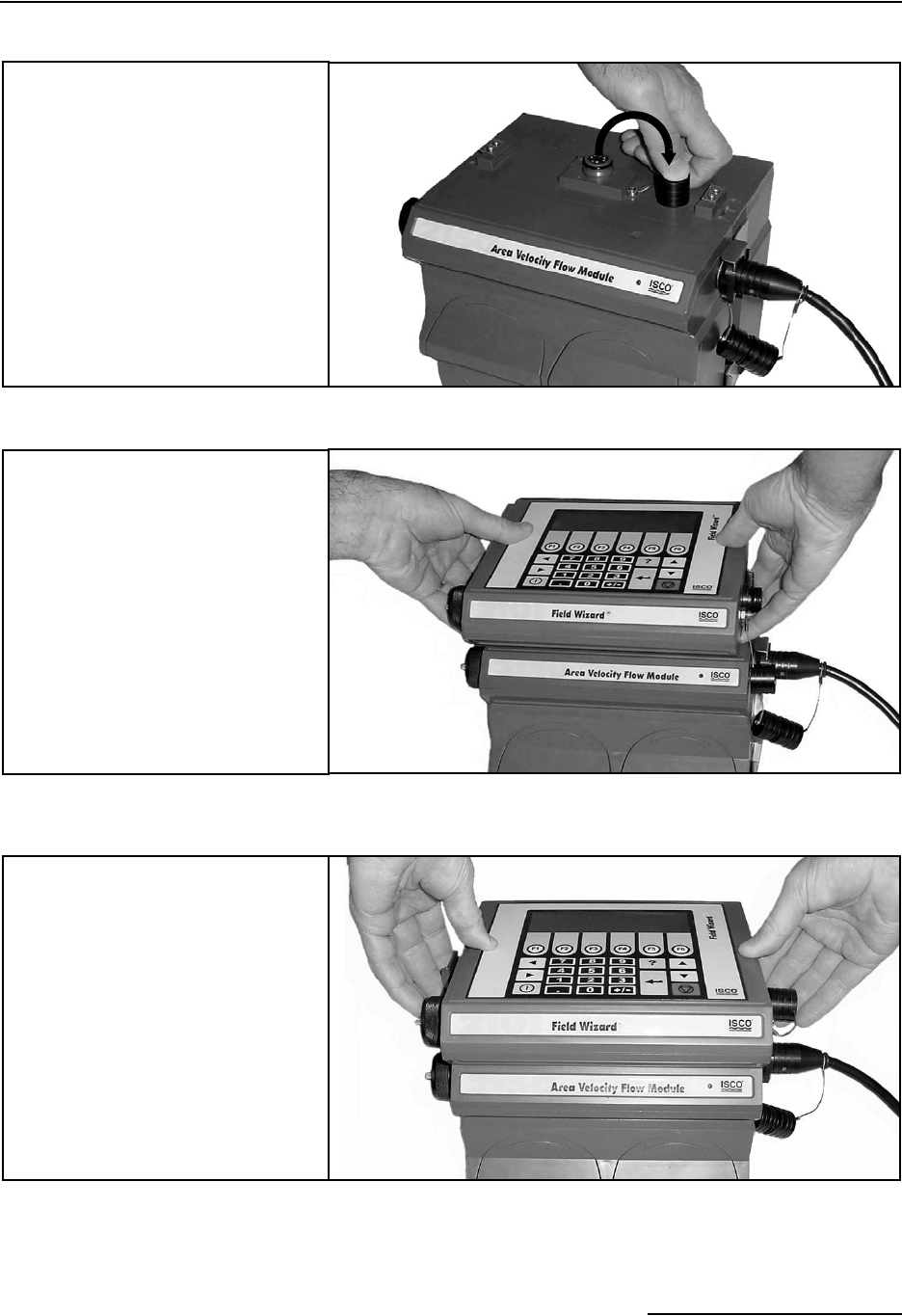
2-9
Figure 2-10:
2100 Series Module -
uncap the connector
Uncap the connector on the top
2100 Series module. Store the
cap on the holder.
Figure 2-11:
Align the modules
Align the modules and gently
press the Field Wizard Module
onto the 2100 Series Module.
Figure 2-12:
Push down and lock
the latch
While gently pressing down on
the stack, lock the Field Wizard
Module’s latch.

2101 Field Wizard
Section 2 Preparation and Installation
2-10
When the Field Wizard is connected to the site, you will hear a
beep and then see the display “PLEASE WAIT...” as the unit
queries the site for configuration information. When it has
obtained that information, it will format it into a display similar
to that in Figure 2-18.
Figure 2-4 Data Retrieval Mode Main Display
More details about operating the Field Wizard at a site can be
found in Section 3.4.

3-1
2101 Field Wizard
Section 3 Operation
3.1 Introduction This section describes how to use a 2101 Field Wizard with Isco’s
Flowlink software, and how to operate the Field Wizard in the
field.
Note
The Field Wizard requires Flowlink 4.12 or later. Earlier ver-
sions do not support the Field Wizard. The Field Wizard also
requires that the 2100 Series modules it connects to have a
code version 1.06 or greater.
Flowlink Help Detailed Flowlink instructions are beyond the scope of this
manual. Flowlink’s operating instructions are available in a
Windows Help format. You can access the help topics for an
active window by clicking on its Help button or by pressing F1 on
your computer’s keyboard. You can also access Help topics by
selecting Help from the Flowlink menu.
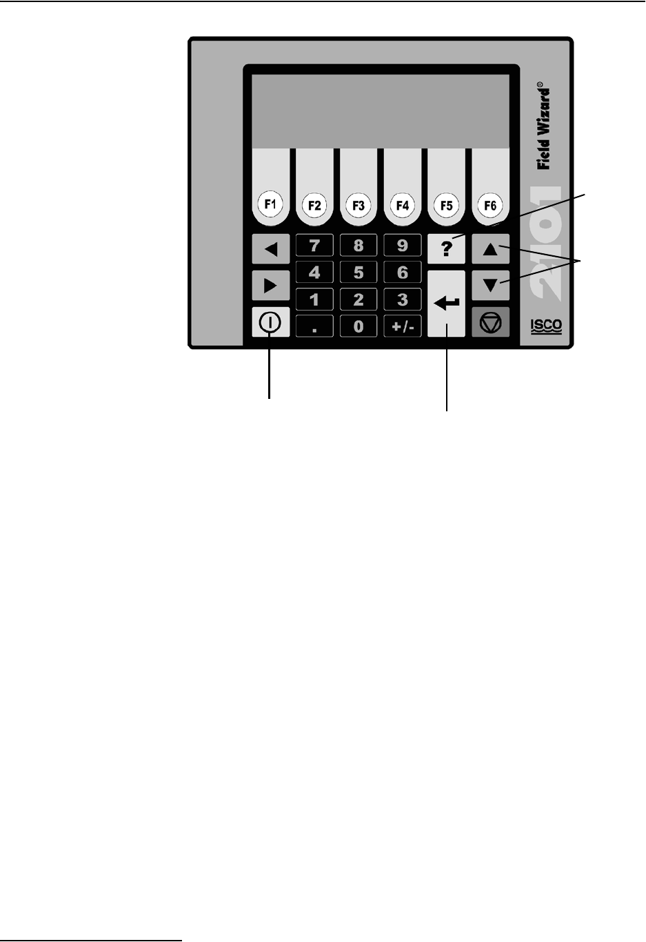
3.2 Field Wizard Keypad The Field Wizard is operated from the top panel, which contains
a keypad and liquid crystal display.
The keypad, shown in Figure 3-1, includes 26 keys that are used
to operate the Field Wizard.
2101 Field Wizard
Section 3 Operation
3-2
Figure 3-1 Field Wizard Keypad and Display
The keypad contains six software configured function keys (soft
keys) that are used to make selections and navigate through
menus. Their specific functions will depend upon what operation
you are performing, and will be shown in the display window.
The four arrow keys are used for navigation. The Enter key is
used to complete data entry, acknowledge prompts, and signal
the start of certain operations. Numeric keys are active when
numeric data is to be entered.
The key with a question mark on it is the Help key. Press it to
obtain context sensitive help while using the Field Wizard. When
you are in Help mode, use the directional arrow keys to scroll
through the information displayed. Press the Help key again to
exit the Help mode.
The Power key places the unit into an ultra low power state,
during which the display window will be blank.
The Escape key is not currently used. During some operations,
one of the function keys will serve as a Cancel or Exit key.
The unit is equipped with an audible beeper. The beeper
acknowledges key presses, and signals errors when incorrect
entries are made.
DWG 69-2003-143
Arrow Keys
Help Key
Numeric Keys
Power Key
Enter Key

2101 Field Wizard
Section 3 Operation
3-3
Note
If the display is difficult to read, adjust its contrast by holding
down the Plus/Minus (+/-) key while pressing the Down or Up
Arrow key until you obtain the desired lighting level.
3.3 Flowlink Connection Before taking the Field Wizard to a site to collect data for the first
time, you need to configure it to your Flowlink software. This will
let you synchronize the Field Wizard’s date and time with that on
your personal computer (PC) and assign a module name to the
Field Wizard for identification. On subsequent connections,
Flowlink will recognize the Field Wizard from information stored
in its database.
The Field Wizard operates as an extension to Flowlink’s Master
Data Base on your PC, which synchronizes the measurement and
collection of data for all sites under its management. This cen-
tralized control insures that all measured data is collected from a
site, and that measurements are taken when expected.
Note
If you will be using the Field Wizard to transfer data to multiple
computers, you should designate one computer as the master
and connect the Field Wizard to it first. This will avoid problems
with synchronizing the date and time.
3.3.1 Connecting To a PC To connect the Field Wizard to a PC, you will need Isco’s commu-
nication cable P/N 60-2004-046 and AC Adapter P/N
60-2004-057.
One end of the AC adapter plugs into a grounded electrical
outlet, and the other end connects to the communications con-
nector on the underside of the Field Wizard.
One end of the communication cable connects to a serial port on
your PC, and the other end connects to the communication con-
nector on the right hand side of the Field Wizard.
Refer to Section 2.3 for more detailed instructions and diagrams
on how to make these connections.
As a default Flowlink setting, the Quick Connect dialog box
opens when you start Flowlink. (If it is not open, click the Quick
Connect icon or select File, Quick Connect.)
Click the large Field Wizard button to connect. Flowlink will
read the 2101 system information and try to match it with an
existing site in the open database. It will then display the Site
Info screen (Figure 3-2).

2101 Field Wizard
Section 3 Operation
3-4
Figure 3-2 Flowlink Site Info Screen
Complete the following steps:
1. Click the Synchronize Instrument’s Time to Com-
puter’s button to synchronize the Field Wizard’s time to
that of your PC. (If you are using multiple PCs, select just
one PC to synchronize with.) You will be notified that this
operation will set the time of the Field Wizard to match
that of the PC. Click OK.
2. The Field Wizard is shipped with default site and module
names. Use the Site Name and Module Name fields if
you want to provide more descriptive names. Select Apply
(F9) to write that information to the instrument.
3. Click Retrieve Data (F8) to retrieve the data from the
Field Wizard. For synchronization purposes, this should be
done even if this is the first time you are connecting the
Field Wizard to the PC. The process transfers a file con-
taining site interrogation times from Flowlink to the Field
Wizard. With this information, the Field Wizard will know
when data was last retrieved from your site(s). When
brought to a site, the Field Wizard will retrieve only the
necessary data.
The process will take some time. A gauge will be displayed
so you can monitor the progress. If needed, click Cancel to
cancel the data transfer. The data will be retained in the
Field Wizard.
Data that has been retrieved by the PC will remain in the
Field Wizard until it is connected to a site and begins col-
lecting new data. This allows you to copy data to multiple
PCs.
4. Select Disconnect to end your PC session and disconnect
the Field Wizard.

2101 Field Wizard
Section 3 Operation
3-5
3.3.2 Communication
Resolution
During the connection process, Flowlink checks the stability of
the site’s communications. If communication is found to be
unstable, Flowlink presents the Communication Resolution
window.
There are two common causes of unstable communications. One
cause is a Module Name conflict, which may occur when two or
more modules at a site use the same module name. The second
cause is a Site Name conflict, which occurs when a module added
to the site indicates that it belongs to a different site.
The Communications Resolution window lets you choose how the
modules should be reconfigured and which Site Name should be
retained. To resolve the communications, select the sites and
modules that should be reconfigured and click the OK button. Be
aware that reconfiguring a module removes the Site Name,
Module Name, program settings, and any stored data. The
module is then restarted with the stable Site’s Name, a default
Module Name, and default program settings, and the data
storage is ready to accept new data.
3.3.3 Site and Module Name The Field Wizard is shipped with a default site and module name
so it can immediately begin to communicate with Flowlink. You
can change the names to something more descriptive using the
Site Name and Module Name fields on the Site Info tab in
Flowlink.
Keep in mind that the names must be unique among the other
site and module names in the open Flowlink database. Site
names can be up to 37 characters long. Any character may be
used in the name except:
/ forward slash \ back slash
: colon * asterisk
? question mark “ double-quote
< left angle bracket > right angle bracket
|bar
2101 Field Wizard
Section 3 Operation
3-6
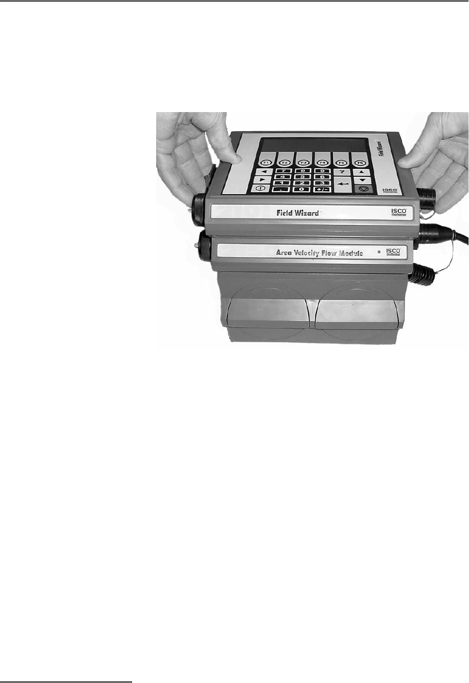
3.4 Connecting to a Site Once you have connected the Field Wizard to Flowlink and set up
the initial configuration, you can connect the Field Wizard to a
site and retrieve data.
To connect the Field Wizard, refer to the following instructions
and to Figure 3-3. For more details and a series of photos
showing the connection steps, refer to Section 2.4.
Figure 3-3 Field Wizard Connected to a 2150 Site
The Field Wizard module connects to the top of a 2100 Series
stack, which may contain multiple 2100 Series Modules.
1. On the top 2100 Series Module, remove the connector cap
from the communication connector and store the cap in its
holder.
2. Unlock the Field Wizard’s latch by pressing in on the latch
release (right side).
3. Underneath the Field Wizard module, remove the cap from
the communication connector and store the cap in its
holder.
4. Lock the Field Wizard’s latch by pressing in on the latch on
the left side. This correctly seats and aligns the cap in its
holder.
5. Position the Field Wizard over the 2100 Series Module.
Align the connectors and lower the Field Wizard onto the
Module.
6. Unlock the Field Wizard’s latch.
7. Firmly press the modules together and lock the Field Wiz-
ard’s latch.
2101 Field Wizard
Section 3 Operation
3-7
3.5 Site Time
Synchronization
The Field Wizard operates as an extension of the Master Data
Base computer, which is responsible for synchronizing the mea-
surement and collection of data for all sites under its man-
agement. This centralized control insures that all measured data
is collected from a site, and that measurements are taken when
expected.
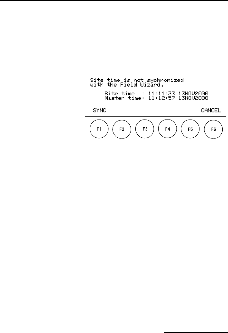
When the Field Wizard is connected to a site, its date and time
will be checked with that of the site. If the Field Wizard detects a
time difference of more than one minute, the following screen
will be displayed:
Figure 3-4 Synchronize Time Display
Press F1 SYNC to synchronize the site’s time with that of the
Field Wizard and the Master Computer. The time will be syn-
chronized and you will be advanced to the Data Retrieval Mode
Main Display (Fig. 3-5).
If you do not want to synchronize the time, press F6 CANCEL to
advance to the Data Retrieval Mode Main Display (Fig. 3-5).
3.6 Data Retrieval Mode The Field Wizard will be in data retrieval mode when collecting
data from modules in the field. When the Field Wizard is con-
nected to the site, you will hear a beep and then see the display
“PLEASE WAIT...” as the unit queries the site for configuration
information. When it has obtained that information, and
assuming that the site’s time is synchronized with the Field
Wizard, you will see a display similar to that in Figure 3-5.
2101 Field Wizard
Section 3 Operation
3-8
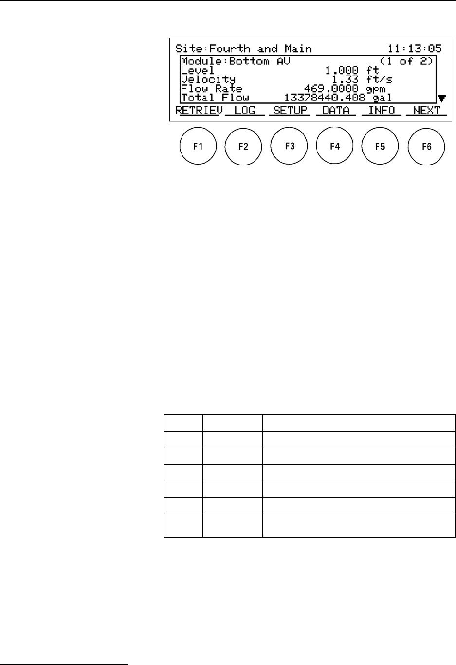
Figure 3-5 Data Retrieval Mode Main Display
On the Data Retrieval Mode Main Display, the site name and
current time and date will be shown on the top line.
The module name and current measurement information will be
shown in the window. If more than one module is detected, an
indicator (X of X) after the module name will show what module
is currently being displayed and the total number of modules
found at the site.
All of the measurement data shown is live and will be updated
every fifteen seconds. If the module has more information than
can be displayed at one time, scroll arrows will appear on the
right side of the screen. Pressing the Up and Down arrow keys
will scroll through the complete information for that module.
Press F6 NEXT to display data for the next module (if there are
two or more 2100 Series modules).
The actions assigned to the function keys are summarized below.
More complete descriptions are provided in the subsections that
follow.
KEY FUNCTION DESCRIPTION
F1 RETRIEVE Used to collect data from the site.
F2 LOG Checks the status of currently stored data.
F3 SETUP Used to maintain the site after setup on a PC.
F4 DATA Displays data storage statistics.
F5 INFO Examines system information about active modules.
F6 NEXT Moves to next module when multiple modules exist;
is not active when there is just one module at a site.
2101 Field Wizard
Section 3 Operation
3-9
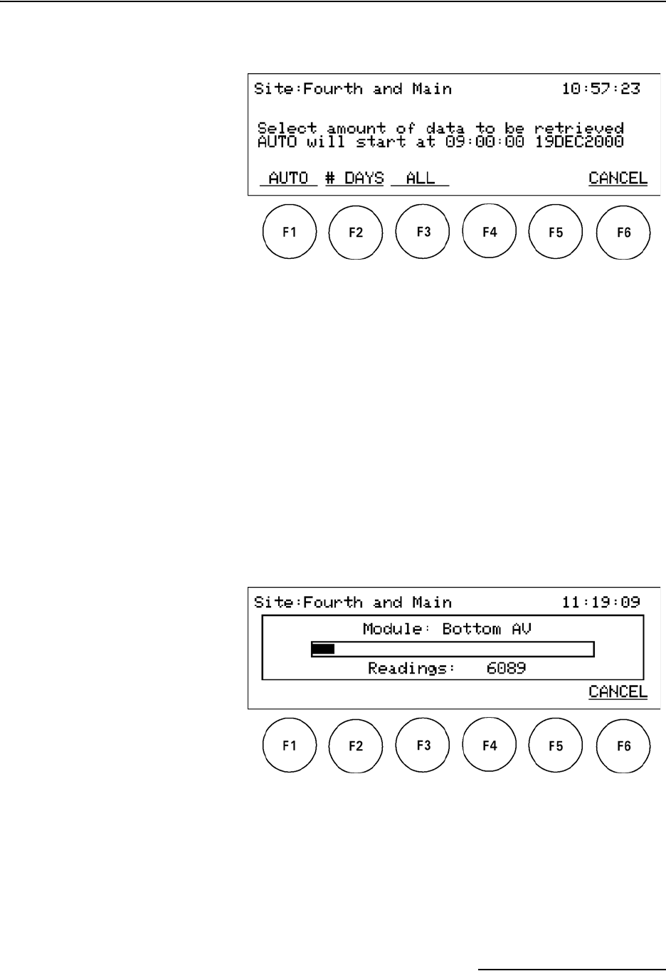
3.6.1 Retrieve Data Display When you press F1 RETRIEVE from the Main Display, the
window shown in Figure 3-6 will be displayed.
Figure 3-6 Retrieve Data Display
The Retrieve Data display has four function key options, as
described below.
F1 AUTO – Press the F1 key to retrieve data from the starting
point in time scheduled by the Master Data Base. This time is
generated each time the Field Wizard transfers data to Flowlink.
A message in the Field Wizard window will tell you the time and
date that data collection will start if you select this option.
During data collection, the name of the module being interro-
gated will be displayed, along with a gauge so you can note the
progress (see Figure 3-7).
If there is more than one module active at the site, then the data
will be retrieved one module at a time. One module will be com-
pletely interrogated before data will be retrieved from any other
module.
Figure 3-7 Data Retrieval Status Display
Information inside the status window will change as the interro-
gation process proceeds. As the data is being retrieved, both the
gauge and number of readings will change.
If you want to cancel the data collection process, press F6. This
will return you to the Main Display, and will save the data that
has already been collected.
2101 Field Wizard
Section 3 Operation
3-10
If the data being retrieved exceeds the Field Wizard’s available
memory, data retrieval will be terminated and you will be
notified of an incomplete retrieval. All the data retrieved from
the start time to the point memory was filled will be saved in the
Field Wizard and can be downloaded to a PC.
When data collection is complete, an audible signal will sound,
and you will be returned to the Main Display.
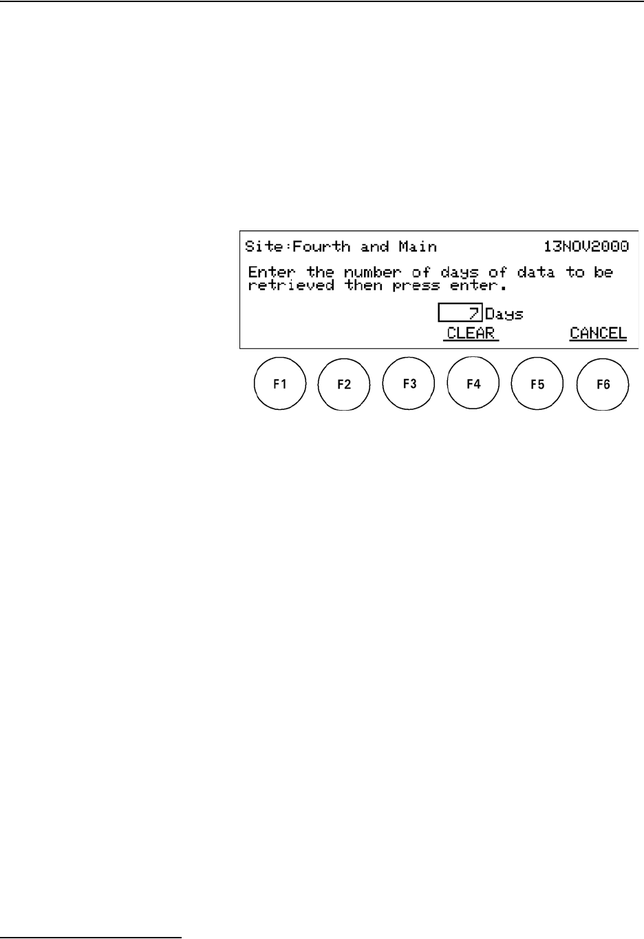
F2 # DAYS – When you press the F2 key from the Retrieve Data
Display, you will be prompted to enter the number of days for
which data is to be retrieved. You will see the screen display
shown in Figure 3-8.
Figure 3-8 Retrieve # Days Display
Use the number keys on the keypad to enter the number of days
for which you want data to be retrieved. Press Enter.
To clear the number of days and reset it to zero, press F4 CLEAR.
To cancel your entry and return to the previous screen, press F6
CANCEL.
The system will take the current date and retrieve data starting
at midnight, including the current day (which is counted as day
zero). For example, if the current date was March 11, and you
requested to retrieve data for the past 7 days, data retrieval
would start at the beginning of March 4 and would include data
through March 11. As another example, if you entered zero (0)
days, data would be retrieved for the current day, beginning at
midnight.
During data collection, the name of the module being interro-
gated will be displayed, along with a gauge so you can note the
progress.
To cancel the data collection process, press F6 CANCEL. When
data collection is complete, an audible signal will sound, and you
will be returned to the Main Display.
F3 ALL – Pressing the F3 key from the Retrieve Data Display
will retrieve all data that has been stored in the modules, up to
the current time and date. This process will take some time.
F6 CANCEL – Press the F6 key from the Retrieve Data Display
to return to the Main Display.

2101 Field Wizard
Section 3 Operation
3-11
3.6.2 Data Retrieval Log
Display
When you press F2 LOG from the Main Display, the window
shown in Figure 3-9 will be displayed.
Figure 3-9 Log Display
This display contains historical information on data that has
already been retrieved from the site and stored in the Field
Wizard. It also includes information about the status of the Field
Wizard’s storage memory.
The historical data is listed by site name, with the most recently
retrieved one listed first. The site name is followed by the time
and date the data was retrieved. An indication of the data’s han-
dling state is listed under the “Saved” header. When data is first
collected, it will have a state of “No.” After the data has been
transferred to the Master Database on the PC, the state will
change to “Yes.”
Once you have transferred a site’s data to the Master Database
in Flowlink, it is eligible to be purged, thus freeing up memory
space to collect more data. Note, however, that site data with a
handling state of “Yes” will not be purged until the Field Wizard
has been connected to a site and data retrieval has been ini-
tiated. This allows you to transfer site data to multiple PCs
before purging the data.
Use the Up and Down arrow keys to scroll through the list of
sites. Once you have highlighted a site, you can view more
detailed information for the modules at that site by pressing F3
DETAILS.

2101 Field Wizard
Section 3 Operation
3-12
F3 DETAILS – When you press F3 DETAILS, a screen similar
to the one in Figure 3-10 will be displayed.
Figure 3-10 Data Log Details Display
The detailed information for a site is contained in a scrolling text
window. Use the directional arrow keys to move within the
window and view the data.
The information identifies the time and date of the interrogation
and lists readings for each module at that particular site.
To exit the display and return to the Log Display, press F6 EXIT.
3.6.3 Site Setup Display The Site Setup displays shown in Figures 3-11 and 3-13 are
accessed by pressing F3 SETUP from the Main Display. One of
the Setup displays is for the Field Wizard; the other is for 2100
Series modules in the site’s stack.
Press F2 NEXT to move between modules. An indicator (X of X)
after the module name will indicate the total number of modules.
The Field Wizard itself is considered one of the modules.
Use the Setup displays to adjust the backlighting for the Field
Wizard and calibrate sensors and run diagnostics on the 2100
Series modules.
2101 Field Wizard
Section 3 Operation
3-13
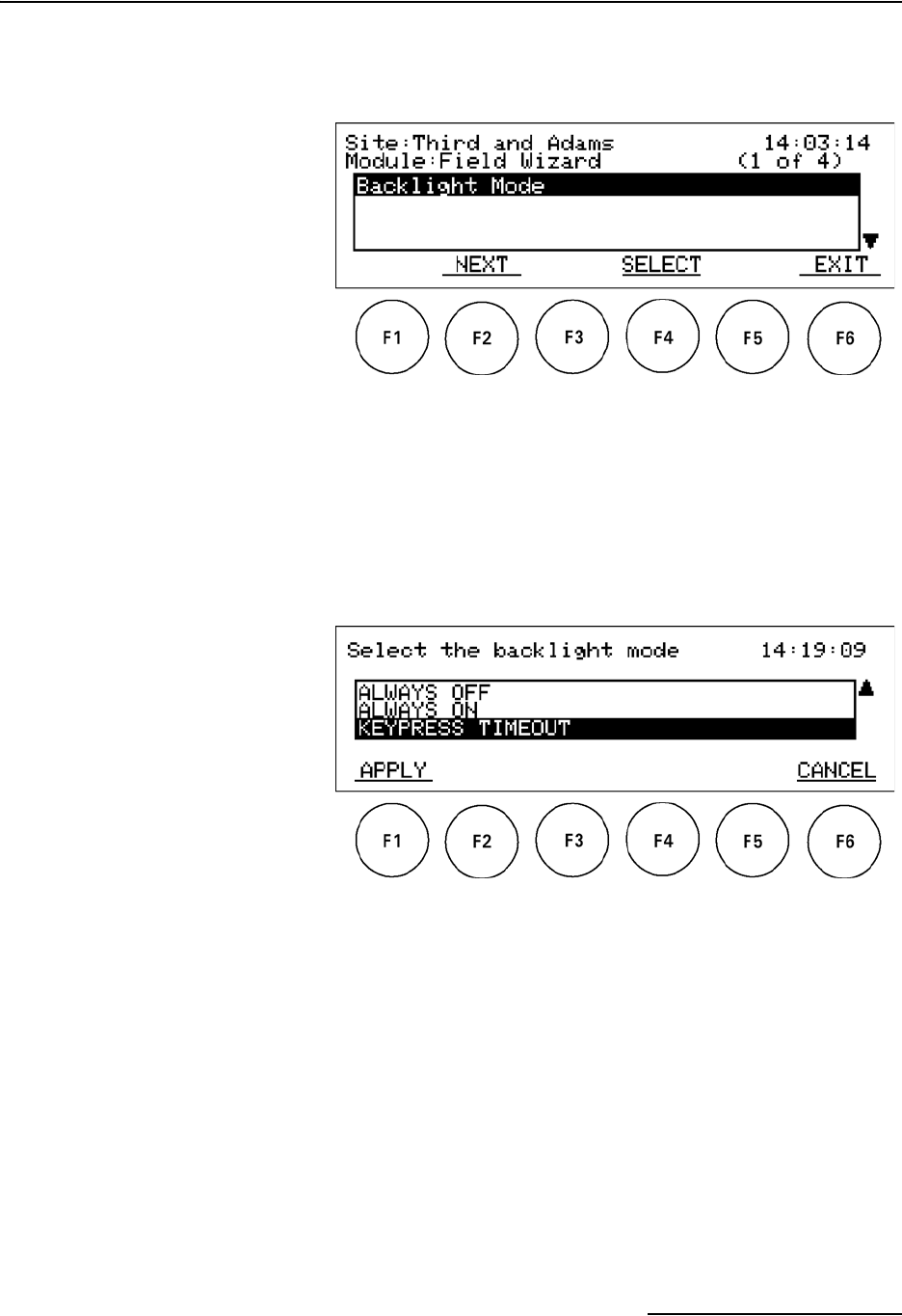
Field Wizard Backlight Mode – When you press F2 NEXT
and advance to the Field Wizard module, the Setup display in
Figure 3-11 will be shown.
Figure 3-11 Field Wizard Site Setup Display
If you press F2 NEXT, you will advance to the next module’s Site
Setup display screen. If you press F6 EXIT, you will return to the
Data Retrieval Mode Main Display.
Press F4 SELECT to change the backlight mode for the Field
Wizard. The following screen will be displayed:
Figure 3-12 Field Wizard Backlight Mode Settings
There are three options for the backlight mode on the Field
Wizard. Highlight the desired option and press F1 APPLY to
select that option. Press F6 CANCEL to return to the Field
Wizard Site Setup display.
ALWAYS OFF - The backlight will always be off.
ALWAYS ON - The backlight will always be on.
KEYPRESS TIMEOUT - After one minute of inactivity, the back-
light will turn off until a key is pressed.
2101 Field Wizard
Section 3 Operation
3-14
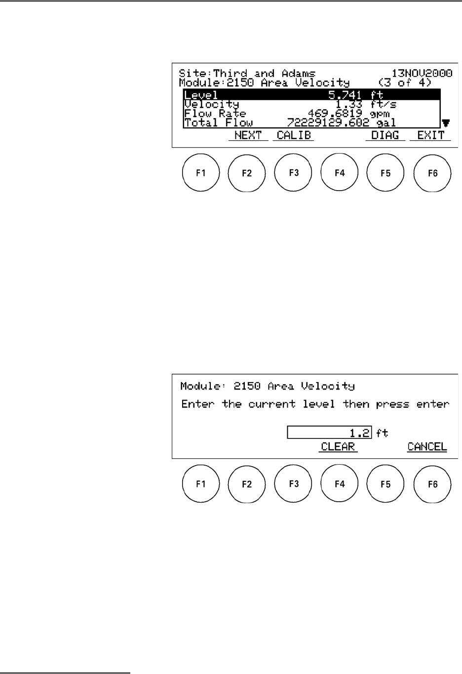
2100 Series Site Setup – If you press F2 NEXT and advance to
a 2100 Series module, the Setup display shown in Figure 3-13
will appear.
Figure 3-13 Site Setup Display
The Site Setup display is used to calibrate sensors and run diag-
nostics on sensors. Module sensor information, such as level and
flow rate, is presented inside the display window. Use the Up and
Down arrow keys to scroll within the window.
Measurement Calibration – Level sensors can be calibrated
using the Field Wizard. Before you can calibrate, one valid
reading must have been taken so there is a value to calibrate to.
On the Site Setup display, use F2 NEXT to display the module
you want to calibrate, then press F3 CALIB. The Level Cali-
bration window for the selected module will appear (Figure 3-14).
Figure 3-14 Level Calibration Display
The level currently being detected will be displayed. To change
the level, use the numeric keys and then press Enter. You will be
returned to the Site Setup display. The message “Updating” will
appear in the Level field momentarily while the system updates
its information.
To clear an entry, press F4 CLEAR. To cancel the process and
return to the Site Setup display, press F6 CANCEL.
2101 Field Wizard
Section 3 Operation
3-15
Sensor Diagnostics – When you press F5 DIAG from the Site
Setup display, the diagnostic screen shown in Figure 3-15 will be
displayed.
Figure 3-15 Sensor Diagnostics Display
After a momentary delay, during which the Field Wizard
requests the report from the 2100 Series module, a screen con-
taining diagnostic results for the selected module’s sensors will
appear. Use the four directional arrow keys to scroll through the
information.
Once you have viewed the information, press F6 EXIT to exit to
the Site Setup display.
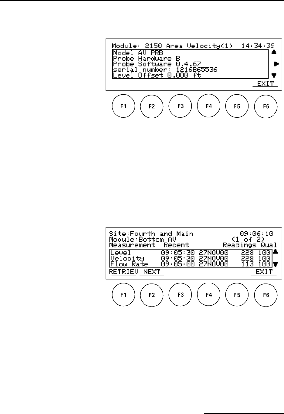
3.6.4 Data Display When you press F4 DATA from the Main Display, the Data
screen shown in Figure 3-16 will appear.
Figure 3-16 Data Display
This display shows information about the data stored inside the
currently selected module: the time and date of the most recent
reading, total number of readings, and the quality of the readings
(percentage that are good). Use the Up and Down arrow keys to
scroll through the information.
When multiple 2100 Series modules are present, you can press
F2 NEXT to display the information for a different module.
2101 Field Wizard
Section 3 Operation
3-16
Press F1 RETRIEV to retrieve the data for the displayed module.
You will be advanced to the Retrieve Data Display, described in
Section 3.6.1.
Press F6 EXIT to return to the Main Display.
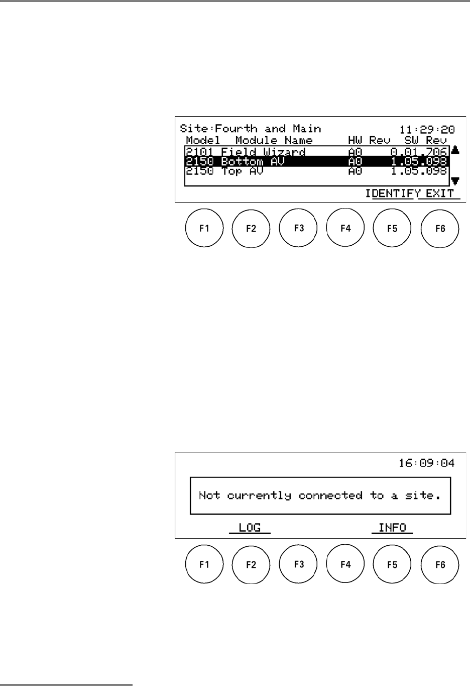
3.6.5 Site Information
Display
When you press F5 INFO from the Main Display, the Site Infor-
mation screen is displayed (Figure 3-17).
Figure 3-17 Site Information Display
This screen shows information about module models and names,
as well as hardware and software revision numbers. Use the Up
and Down arrow keys to scroll between the different modules.
To identify a module, highlight it using the arrow keys and then
press F5 IDENTIFY. This will cause the LED for that module to
light up continuously for a short period of time. If you press F5
IDENTIFY when Field Wizard is highlighted, the system beeps.
Press F6 EXIT to return to the Main Display.
3.7 Standalone Mode When the Field Wizard is not connected to a site or a PC, it is in
standalone mode. The Main Display in standalone mode is shown
in Figure 3-18.
Figure 3-18 Standalone Mode Main Display
In this mode, you can examine the data log stored inside the
Field Wizard unit, but will not be able to view or process the
actual data.
2101 Field Wizard
Section 3 Operation
3-17
To view the data retrieval log, press F2 LOG. The display will be
similar to that shown in Figure 3-9 and described in Section
3.5.2.
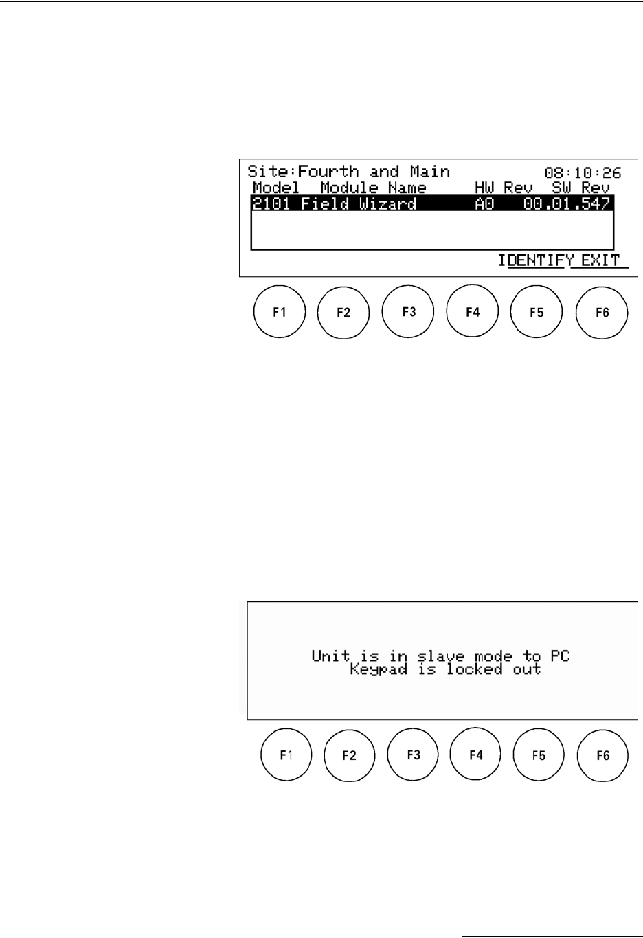
3.7.1 Standalone
Information Display
Pressing F5 INFO while in the standalone mode will display the
Standalone Information screen (Figure 3-19).
Figure 3-19 Standalone Information Display
This screen is similar to that described in Section 3.5.4, except
that it only lists information pertaining to the Field Wizard itself.
Because it is not connected to a site, there isn’t any module infor-
mation.
To exit from the Standalone Information Display, press F6 EXIT.
3.8 PC Data
Synchronization Mode
When the Field Wizard is connected to a PC, the user interface
(keypad) is locked out to prevent any errors while transmitting
data to the PC.
In this mode, the Field Wizard’s display looks like that shown in
Figure 3-20.
Figure 3-20 PC Data Synchronization Mode Display
The Field Wizard’s keypad will not function in this mode, but will
return to normal function when the Field Wizard is disconnected
from the PC.

2101 Field Wizard
Section 3 Operation
3-18

4-1
2101 Field Wizard
Section 4 Modbus Protocol
Sections 4.1 through 4.5 give an overview of the basic capabilities
and operation of Modbus protocol as it applies to Isco 2100 Series
flow modules.
For a Glossary of Terms and Common Acronyms, see sections 4.4
and 4.5.
For Modbus technical specifications, turn to section 4.6.
4.1 Introduction Modbus is a simple command/response mechanism to read from
and write to specific memory locations called registers. A register
is a holding place for a piece of digital information within the
equipment. There are three standard protocols for Modbus:
Modbus RTU, Modbus TCP/IP, and Modbus ASCII. The Isco 2100
Series devices use Modbus ASCII protocol, the method discussed
in this manual. Modbus ASCII has more flexible communication
timing requirements. Modbus communication for the Isco 2100
Series provides a standard protocol that can be used to retrieve
real-time data from a single module or stack of modules at a site,
or multiple sites, over a wide area. The data can be sent to a
central computer for display, data collection, or process control.
Modbus implementation is independent of Flowlink and cannot
alter the Flowlink-programmed configuration of the module.
Modbus cannot be used to retrieve historical data from a
module’s memory.
Due to the wide variety of configurations that can be made with
Modbus, it is impossible to cover every usable application. This
section will discuss the overall capabilities and operation of
Modbus.
4.2 Operation There are many standard, third party Modbus drivers and OPC
servers that may be used to link a remote Modbus device, such as
a 2100 Series module, to SCADA or process control software,
such as Wonderware™ or Intellution™. The OPC server commu-
nicates with the remote instrumentation and accesses registers.
The definition of what information is contained and where (the
register number, or address) is decided by the manufacturer
(Teledyne Isco).
In a 2100 module, the registers hold, but are not limited to, the
current real-time value of the meter’s level, velocity, flow, input
voltage, temperature, and total flow readings, stored in specified
register locations. A list of the 2100 register addresses, and what
parameters are held where, is available in section 4.6.

2101 Field Wizard
Section 4 Modbus Protocol
4-2
By accessing these registers you can obtain the current value of
whatever parameter you desire. The reading(s) can then be dis-
played or stored wherever you designate as a destination; for
example, a process control computer.
Note
Level, flow, velocity, and temperature data is stored in metric
units only.
Not all registers are limited to read-only data storage. You can
also use some registers for control purposes. For example, by
writing a “1” value to register 24 (“Identify Module” register), you
will tell a 2100 module to light the LED on the front of the
module.
4.2.1 Establishing
Communication
There are several different communications protocols supported
in the 2100 series that require auto-baud rate detection. Because
of this, each time a modbus connection is made, the module uses
a polling mechanism to repeatedly send a command until a
response is received. It may take up to 20 command retries
before the module has identified the baud rate and a response is
received.
4.2.2 Module Addressing When connecting to a site via a Modbus OPC server, you use a
dedicated line of communication to that module or stack from the
OPC server, which can be a dedicated communications cable
(direct connection) or a dedicated phone number (modem).
When you are using a direct connection, you are dedicating a
specified COM port on the computer, and that COM port deter-
mines the site to which you are connecting.
When you are using a modem, the dedicated line is defined by
the site's phone number.
If you connect more than one 2100 Series module at a site, the
Modbus OPC server, while using the shared communication line
for all of the modules within the network, must have some way to
differentiate between the modules. When sending a command to
a specific module, the command has an address field. This allows
the server software to talk to, as well as control, the specified
module, while ignoring other modules in the same stack or site.
Each module capable of Modbus Protocol communication will
automatically create its own specific ASCII address within the
site, using:
• The model numbers of the modules
• The user-defined module names
2101 Field Wizard
Section 4 Modbus Protocol
4-3
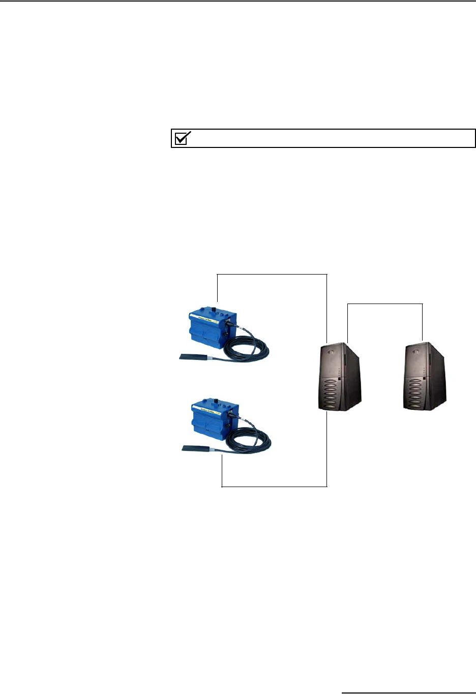
4.3 Configurations A variety of configurations can be made with Modbus, either
through direct connection or through a modem.
In the example shown in Figure 4-1, you are direct-connecting a
server PC to two individual 2150s through Modbus, using the
COM ports on the OPC Server, which are directly connected to
the remote 2150s.
Connection to the module is made through the RS-232 communi-
cation port on the top of the module.
Note
For low power operation, we recommend connecting the mod-
ule(s) to the computer using the straight-through cable (Isco
part number 60-5314-529), which consumes less power,
instead of our standard interrogation cable.
In Figure 4-1, the OPC Server PC must have two COM ports.
Modbus requires one COM port each, for direct connection of
each 2150.
Figure 4-1 Configuration Example (Direct Connection Shown)
The operation sequence for the example above can be summa-
rized in the following steps:
2150:
1. 2150s take readings from probes.
2. 2150s store readings (level, velocity, flow rate, etc.) in their
specified registers.
Process Control:
3. The user requests data through Process Control.
4. Process Control asks the OPC server to gather informa-
tion.
2150
2150
OPC
Server
Process
Control
COM
port 1
COM
port 2

2101 Field Wizard
Section 4 Modbus Protocol
4-4
5. OPC connects to the 2150 stack through the cable (direct
connection), takes register data from the specified 2150,
and populates the OPC server's holding index.
6. Process Control takes data from the OPC server's holding
index and gives data to the user.
Note that Process Control can be either manual or automated in
this example, and that the OPC server and Process Control may
be located physically on the same computer.
4.4 Glossary of Terms ASCII – Short for American Standard Code for Information
Interchange, ASCII is a code that represents English characters
with numbers. Most computers represent text with ASCII code,
making it possible for one computer or device to share data with
another.
2100 modules support Modbus ASCII protocol.
Dedicated Line – A telecommunications path reserved for com-
munication between two specified points and not shared among
multiple points.
Modbus Protocol – Modbus Protocol is a messaging structure
used to establish master-slave/client server communications
between intelligent devices. Modbus is a simple
command/response mechanism to read from and write to reg-
isters.
OPC – OPC (OLE for Process Control) means open connectivity
via open (free for use) standards. It is a series of software stan-
dards specifications that fill a need in automation (like printer
drivers did for Windows), acting as a translator for data trans-
mission and process control.
The specification defines a standard set of objects, interfaces, and
methods for use in process control and manufacturing auto-
mation applications to facilitate interoperability. There are hun-
dreds of OPC Data Access servers and clients.
Registers – Registers are locations in memory that have specific
data stored for retrieval or are used for control functions. A reg-
ister is a holding place for a piece of digital information within
the equipment. The definition of what is contained and where
(the registry number, or address) is decided by the manufacturer
(in this case Teledyne Isco).
SCADA – SCADA (Supervisory Control And Data Acquisition)
is a computer system for gathering and analyzing real-time data.
SCADA systems are used to monitor and control plant operation,
or equipment in industries such as telecommunications, water
and waste control, energy, oil and gas refining, and transpor-
tation.
The SCADA system transfers the information (for example,
where a leak has occurred in a pipeline), back to a central site,
alerting the home station of the leak, performing necessary
analysis and control (such as determining if the leak is critical),
and displaying the information in a logical and organized
manner.

2101 Field Wizard
Section 4 Modbus Protocol
4-5
SCADA systems can be relatively simple, such as one that mon-
itors the environmental conditions of a small office building, or
very complex, such as a system that monitors all the activity in a
nuclear power plant or a municipal water system.
4.5 Common Acronyms ASCII – American Standard Code for Information Interchange
DCS – Distributed Control Systems
MTU – Master Terminal Unit
OPC – Object Linking and Embedding (OLE) for Process Control
PLC – Programmable Logic Controller
RTU – Remote Terminal Unit
SCADA – Supervisory Control And Data Acquisition
TCP/IP – Transmission Control Protocol/Internet Protocol

2101 Field Wizard
Section 4 Modbus Protocol
4-6
4.6 Register Specifications All numbers in the Modbus registers are stored most significant
byte first. If the polling device has a byte ordering of least signif-
icant byte first (an Intel-based PC, for example), the bytes will
need to be reversed after they are received.
The Modbus ASCII address is used to index the data by modules.
Modbus ASCII address 1 contains information related to the site.
The first register contains a 16-bit integer count of the number of
modules that have data to report. The maximum number of
modules that can be supported is 4.
Modbus ASCII addresses 2 through the number of modules plus
1 contain data from the individual modules.
The Modbus ASCII addresses will be sorted by the model
number, and then by module name, which is entered by the user
through Flowlink. This allows the user to control the ordering of
the addresses and easily predict what data will be in specific reg-
isters.
Every measured parameter has a corresponding status and mea-
surement time that are updated with each measurement.
The maximum number of supported measurements from all
modules in the system is 28.
The Modbus registers are assigned within 30 seconds after the
2100 module is powered up. To conserve power for the users who
do not use Modbus communications, no Modbus registers will be
updated with sensor readings until a Modbus master communi-
cates with the 2100 module.
The register definitions for the Site Information device (Modbus
ASCII address 1) are in Table 4-1 below:
Table 4-1 Modbus ASCII Address 1 Register Definitions
Register
Number(s) Name Data type Units Read/Write
1 Number of
modules (N)
(1-4)
16 bit integer None Read
2-20 Site name 38-byte string None Read

2101 Field Wizard
Section 4 Modbus Protocol
4-7
The register definitions for the individual modules (Modbus
ASCII addresses 2-(N+1)) are in Table 4-1 below:
Table 4-2 Modbus ASCII Address 2-(N+1) Register Definitions
Register Number(s) Name Data Type Units Read/Write
1-4 Model number 8-byte string None Read
5-23 Module name 38-byte string None Read
241Identify module 16 bit integer None Read/Write
252Take reading flag 16 bit integer None Read/Write
263Update interval 16 bit integer Seconds Read/Write
274Active flag 1 16 bit field None Read
28 Active flag 2 16 bit field None Read
29 Active flag 3 16 bit field None Read
30 Active flag 4 16 bit field None Read
40,41 Level 4-byte float Meters Read
42 Level status code516-bit integer Read
43-52 Level time record Time6Read
55,56 Velocity 4-byte float Meters/second Read
57 Velocity status code 16-bit integer Read
58-63 Velocity time record Time Read
70,71 Flow 4-byte float Cubic Meters/sec Read
72 Flow status code 16-bit integer Read
73-78 Flow time record Time Read
85,86 Flow 1 4-byte float Cubic Meters/sec Read
87 Flow 1 status code 16-bit integer Read
88-93 Flow 1 time record Time Read
100,101 Volume 4-byte float Cubic Meters Read
102 Volume status code 16-bit integer Read
103-108 Volume time record Time Read
115,116 Volume 1 4-byte float Cubic Meters Read

2101 Field Wizard
Section 4 Modbus Protocol
4-8
(1) A write to the Identify module register will cause the module to perform the identify operation which may be a steady
LED for a few seconds or a beep in the Field Wizard.
(2) Setting the Take Reading flag to 1 will cause the module to update the registers with current data readings. It will
be set to zero when the readings have all been updated. This may be used to initiate readings and poll for when
they are ready to be read. It may take up to 50 seconds to update all the readings, depending upon the flow con-
ditions. Setting the Take Reading flag to 2 causes an automatic, 15 second update of readings when a Modbus
master is polling the 2100.
(3) The Update Interval specifies an interval in seconds that the registers are automatically updated. It defaults to zero,
which indicates that no automatic updating will occur.
(4) The Active Flag (1-4) bit fields specify what fields/registers are active in the list. This provides support for a maxi-
mum of 64 fields. For example, if bit 0 of register 27 is set, the Level (registers 40,41) is active. If bit 1 of register
27 is set, then the Velocity (registers 55,56) is active. If bit 0 of register 28 is set, the Analog channel 7 (registers
265,266) is active.
(5)A non-zero status code indicates a measurement problem.
(6) Time is represented in a series of registers: Order is from lowest address to highest - Seconds (0-59), Minutes (0-59),
Hours (0-23), Days (1-31), Month (1-12) and Year (1977-2099).
117 Volume 1 status code 16-bit integer Read
118-123 Volume 1 time record Time Read
130,131 Voltage 4-byte float Volts Read
132 Voltage status code 16-bit integer Read
133-138 Voltage time record Time Read
145,146 Temperature 4-byte float Degrees Celsius Read
147 Temperature status code 16-bit integer Read
148-153 Temperature time record Time Read
160,161 Internal Temp 4-byte float Degrees Celsius Read
162 Internal Temp status code 16-bit integer Read
163-168 Internal Temp time record Time Read
175,176 Analog channel 1 4-byte float 0-100 percent Read
177 Analog channel 1 status code 16-bit integer Read
178-183 Analog channel 1 time record Time Read
190,191 Analog channel 2 4-byte float 0-100 percent Read
192 Analog channel 2 status code 16-bit integer Read
193-198 Analog channel 2 time Record Time Read
205,206 Analog channel 3 4-byte float 0-100 percent Read
207 Analog channel 3 status code 16-bit integer Read
208-213 Analog channel 3 time record Time Read
220,221 Analog channel 4 4-byte float 0-100 percent Read
222 Analog channel 4 status code 16-bit integer Read
223-228 Analog channel 4 time record Time Read
235,236 Analog channel 5 4-byte float 0-100 percent Read
237 Analog channel 5 status code 16-bit integer Read
Table 4-2 Modbus ASCII Address 2-(N+1) Register Definitions (Continued)
Register Number(s) Name Data Type Units Read/Write

2101 Field Wizard
Section 4 Modbus Protocol
4-9
238-243 Analog channel 5 time record Time Read
250,251 Analog channel 6 4-byte float 0-100 percent Read
252 Analog channel 6 status code 16-bit integer Read
253-258 Analog channel 6 time record Time Read
265,266 Analog channel 7 4-byte float 0-100 percent Read
267 Analog channel 7 status code 16-bit integer Read
268-273 Analog channel 7 time record Time Read
280,281 Analog channel 8 4-byte float 0-100 percent Read
282 Analog channel 8 status code 16-bit integer Read
283-288 Analog channel 8 time record Time Read
Table 4-2 Modbus ASCII Address 2-(N+1) Register Definitions (Continued)
Register Number(s) Name Data Type Units Read/Write
Table 4-3 Measurement Parameters by Model Number*
2103, 2103C 2108 2110 2150, 2151
Voltage Analog channel 1 Level Level
Analog channel 2 Flow Velocity
Analog channel 3 Volume Flow
Voltage Flow 1
Temperature Volume
Volume 1
Voltage
Temperature
*Subject to change.

2101 Field Wizard
Section 4 Modbus Protocol
4-10

5-1
2101 Field Wizard
Section 5 Maintenance
5.1 Maintenance
Overview
This section explains the maintenance requirements of the 2101
Field Wizard.
The Field Wizard is designed to perform reliably in adverse con-
ditions with a minimal amount of routine service requirements.
To keep your system working properly, you should check the des-
iccant and channel conditions at regular intervals.
Maintenance intervals are affected by many variables. Humidity
levels obviously affect the service life of the desiccant, and the
amount of debris in the stream can drastically alter the channel
conditions.
As a guide, for a basic system installed in an environment with
moderate humidity levels, the maintenance interval should not
exceed three months. A basic system is defined as:
• a single 2100 Series Module,
• powered by a fresh pair of alkaline lantern batteries,
• recording readings at the default intervals of 15
minutes.
Experience is often the best tool to use when establishing
minimum maintenance intervals for your system. Until you have
gained an understanding of the A-V Module’s operation under
differing environmental conditions, a weekly maintenance
interval is recommended.
5.1.1 Cleaning The Field Wizard case may be cleaned using a soft cloth and a
mild detergent. Do not use an abrasive cleanser, or you might
scratch the surface of the case. Be particularly careful when
cleaning the display screen; scratches will make it difficult to
read the display
Before cleaning, make sure that all the protective connector caps
are in place to avoid damage to any of the connectors. You should
also ensure that no water or cleanser enters the desiccant unit.
5.2 Maintenance Kit Some of the parts mentioned in the Maintenance section of this
manual are available in a maintenance kit.
Kit number 60-2009-001 contains O-rings for the connectors and
desiccant cartridge, a desiccant assembly, and a 1.5 pound con-
tainer of silica gel desiccant.
You can order the kit by calling Teledyne Isco’s Customer Service
Department.
Teledyne Isco, Inc.
Customer Service Dept.
P.O. Box 82531
Lincoln, NE 68501 USA
Phone: (800) 228-4373
(402) 464-0231
FAX: (402) 465-3022
E-mail: info@isco.com
2101 Field Wizard
Section 5 Maintenance
5-2
5.3 Desiccant The Field Wizard uses desiccant to protect the internal compo-
nents from moisture damage. The cartridge is filled with indi-
cating silica gel that is blue or yellow when dry. As the desiccant
becomes saturated, the color changes from blue to pink, or from
yellow to green. Replace the desiccant before the entire length of
the cartridge turns pink or green.
5.3.1 Replacing the
Desiccant: 2101
The desiccant is contained in a cartridge located on the left side
of the Field Wizard. To remove the cartridge, unscrew the collar
and slide the cartridge out of the Field Wizard. The clear tube
reveals the silica gel desiccant inside.
To replace the silica gel desiccant:
1. Hold the cartridge upright with the collar at the top.
2. As shown in the margin, push the collar off the cartridge.
3. Empty the saturated silica gel beads or granules.
4. Fill the tube with new (Isco P/N 099-0011-03) or reacti-
vated (see section 4.3.2) silica gel desiccant.
5. Press the collar onto the tube.
6. Slide the cartridge into the Field Wizard. Tighten the col-
lar to seal the cartridge in place.
5.3.2 Reactivating the
Desiccant
Silica gel beads and granules of desiccant can be reactivated.
CAUTION
Desiccant may produce irritating fumes when heated. Observe
the following precautions:
• Use a vented oven in a well-ventilated room.
• Do not remain in the room while the regeneration is taking
place.
• Use the recommended temperature. Avoid heating the
desiccant at higher than recommended temperatures.
There have been reports of irritating fumes coming from the des-
iccant during reactivation. While our attempts to duplicate the
problem have been unsuccessful, we still urge you to use caution.
Material Safety Data Sheets are in the back of this manual.
The desiccant’s ability to remove moisture may lessen with each
saturation/reactivation cycle, resulting in a need for more fre-
quent service. After several cycles, the desiccant may no longer
be effective as it saturates too quickly. At this point, replace the
desiccant.
Silica gel To reactivate the silica gel desiccant, pour the spent desiccant
into a heat resistant container. Never heat the cartridge
assembly; it will melt. Heat the silica gel in a vented convection
Collar
Cartridge

2101 Field Wizard
Section 5 Maintenance
5-3
oven at 212° to 350°F (100° to 175°C) for two to three hours, or
until the blue or yellow color returns. Allow the desiccant to cool
and store it in an airtight container until ready for use.
5.4 Hydrophobic Filter If the Field Wizard module is submerged, a hydrophobic filter
prevents water from entering the desiccant cartridge. Any
amount of water will plug the filter and it must be replaced so
the case will be reliably ventilated. Ventilation is needed to
equalize pressure within the Field Wizard to prevent the keypad
label from warping.
To remove the hydrophobic filter, grasp the filter and pull it from
the desiccant cartridge collar. The filter is only held in place by
its friction fitting; rocking it back and forth while pulling may
help. Firmly press the replacement filter (Isco P/N 60-2005-003)
in place.
If the hydrophobic filter frequently requires replacement, you
should consider relocating the modules so that they are better
protected. Alternatively, replace the existing hydrophobic filter
with the reference extension accessory package included with
your unit. Follow the instructions above to remove and replace
the filter. Locate the other end of the tubing in a dry location and
secure it.
5.5 How to Obtain Service The internal components of the Field Wizard are not user-ser-
viceable. The case is completely sealed to protect the internal
components. To repair the unit, the case must be broken open
and replaced. If you think your module requires repair, contact
Teledyne Isco’s Technical Service Department.
Teledyne Isco, Inc.
Technical Service Dept.
P.O. Box 82531
Lincoln, NE 68501 USA
Phone: (800) 228-4373
(402) 464-0231
FAX: (402) 465-3085
E-mail: service@isco.com
Corresponding with a Teledyne Isco Technical Service Represen-
tative can often resolve the problem without the need to return
the item. If the difficulty cannot be resolved you will be issued a
Return Authorization Number (RAN) and information on
returning it to the factory.

2101 Field Wizard
Section 5 Maintenance
5-4

A-1
2101 Field Wizard
Appendix A Replacement Parts
A.1 Replacement Parts Replacement parts are called out in the following illustration.
Refer to the call-out in the adjacent list to determine the part
number for the item.
Replacement parts can be purchased by contacting Teledyne
Isco’s Customer Service Department.
Teledyne Isco, Inc.
Customer Service Department
P.O. Box 82531
Lincoln, NE 68501 USA
Phone: (800) 228-4373
(402) 464-0231
FAX: (402) 465-3022
E-mail: info@isco.com
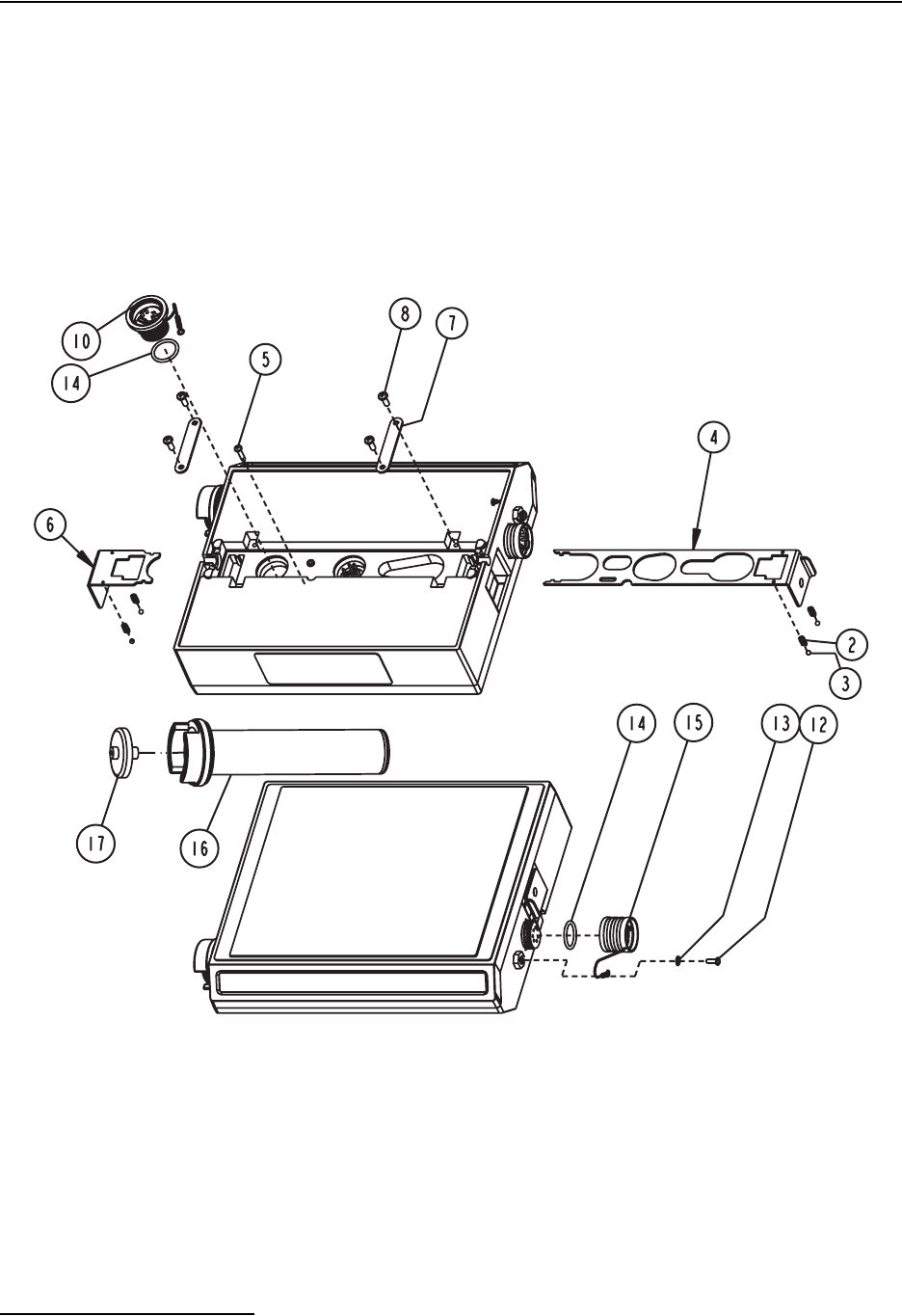
2101 Field Wizard
Appendix A Replacement Parts
A-2
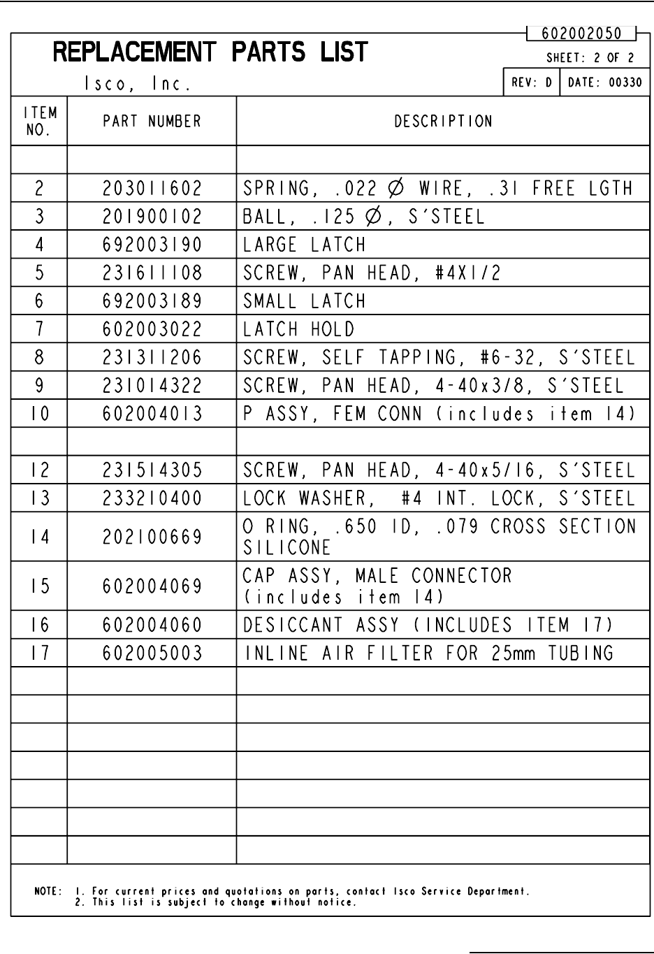
2101 Field Wizard
Appendix A Replacement Parts
A-3

2101 Field Wizard
Appendix A Replacement Parts
A-4

B-1
2101 Field Wizard
Appendix B Accessories
B.1 How to Order Accessories can be purchased by contacting Isco’s Customer
Service Department.
Teledyne Isco, Inc.
Customer Service Dept.
P.O. Box 82531
Lincoln, NE 68501 USA
Phone: (800) 228-4373
(402) 464-0231
FAX: (402) 465-3022
E-mail: info@isco.com
B.2 General Accessories Field Wizard Instruction Manual . . . . . . . . . . . . . . . . 60-2003-155
Flowlink for Windows Software . . . . . . . . . . . . . . . . . 69-2543-144
Communication Cable . . . . . . . . . . . . . . . . . . . . . . . . . 60-2004-046
AC Adapter. . . . . . . . . . . . . . . . . . . . . . . . . . . . . . . . . . 60-2004-057
Field Wizard Maintenance Kit . . . . . . . . . . . . . . . . . . 60-2009-001
Silica Gel Desiccant . . . . . . . . . . . . . . . . . . . . . . . . . . . 099-0011-03
Hydrophobic Filter. . . . . . . . . . . . . . . . . . . . . . . . . . . . 60-2005-003
Tubing, 10’ Silicone . . . . . . . . . . . . . . . . . . . . . . . . . . . 60-2003-104

2101 Field Wizard
Appendix B Accessories
B-2

C-1
2101 Field Wizard
Appendix C Material Safety Data Sheets
C.1 Overview This appendix to the manual provides Material Safety Data
Sheets for the desiccant used by the 2101 Field Wizard and 2191
Battery Module.
Isco cannot guarantee the accuracy of the data. Specific ques-
tions regarding the use and handling of the products should be
directed to the manufacturer listed on the MSDS.

2101 Field Wizard
Appendix C Material Safety Data Sheets
C-2
MATERIAL SAFETY DATA SHEET
Effective Date March 8, 2005
MSDS Number M163
Section 1 – Product and Company Information
Product Name: Silica gel, indicating, yellow
Product Use: Desiccant, absorbent
Grades: Silica gel, indicating
Synonyms: Amorphous silica gel, SiO
2
, silicon dioxide (amorphous)
Company; Multisorb Technologies, Inc.
Street Address: 325 Harlem Road
City, State, Zip, Country: Buffalo, NY 14224-1893 USA
Telephone Number: (716) 824 8900 [USA] Monday - Friday (8:00 - 5:00 EDT)
Fax Number: (716) 824 4091 [USA]
Website / E-Mail : multisorb.com
Section 2 – Composition / Information on Ingredients
Component Name CAS Number % by Weight
Synthetic amorphous silica gel (SiO
2
) 112926-00-8 100
Phenolphthalein 77-09-08 100 ppm
While this material is not classified, this MSDS contains valuable information critical to the safe handling
and proper use of this product. This MSDS should be retained and available for employees and other users
of this product.
Section 3 – Hazard Identification
Emergency Overview: A yellow bead or granular material that poses little or no immediate hazard.
This material is not combustible.
Potential Health Effects:
Eyes: Dust and or product may cause eye discomfort and irritation seen as tearing and reddening.
Skin: The product dust may cause drying of the skin. Silica gel may get hot enough to burn skin
when it adsorbs moisture rapidly. Use an excess of water to cool the silica gel.
Ingestion: Material is not toxic and will pass through the body normally.
Inhalation: Slight irritation is possible but none is expected.
Medical Effects Generally Aggravated by Exposure:
Respiratory ailments.
Chronic Effects/Carcinogenity:
May cause eye, skin and mucous membrane irritation and drying.

2101 Field Wizard
Appendix C Material Safety Data Sheets
C-3
Section 4 – First Aid Measures
Eyes: Rinse the eyes well with water while lifting the eye lids. If irritation persists, consult a
physician.
Skin: Wash affected area with soap and water.
Ingestion: Ingestion is unlikely, this material will pass through the body normally.
Inhalation: Remove the affected person to fresh air and get medical attention if necessary.
Notes to Physician: Not applicable
Section 5 – Fire Fighting Measures
Flammable Properties: Not flammable
Flash Point: Not applicable Method: Not applicable
Flammable Limits: Not flammable
Lower Flammability Limit: Not applicable
Upper Flammability Limit: Not applicable
Autoignition Temperature: Not applicable
Hazardous Combustion Products: Not applicable
Extinguishing Media: Use extinguishing media that is appropriate for the surrounding fire. Silica gel is
not combustible.
Fire Fighting Instructions: Not combustible
Unusual Fire and Explosion Hazards: None
Section 6 – Accidental Release Measures
Spill: Sweep or vacuum up and place the spilled material in a waste disposal container. Avoid raising dust.
Wash with soap and water after handling.
Section 7 – Handling and Storage
Handling: Avoid raising dust and minimize the contact between worker and the material. Practice
good hygienic work practices.
Storage: Store in a cool, dry location. Keep in sealed containers away from moisture. The silica gel
will readily adsorb moisture.

2101 Field Wizard
Appendix C Material Safety Data Sheets
C-4
Section 8 – Exposure Controls/Personal Protection
Engineering Controls: Use exhaust ventilation to keep the airborne concentrations below the exposure
limits.
Respiratory Protection: Use NIOSH approved respirator when the air quality levels exceed the TLV's.
Skin Protection: Light gloves will protect against abrasion and drying of the skin.
Eye Protection: Safety glasses.
Component Name Exposure Limits
OSHA
PEL
ACGIH
TLV
Other
Recommended
Limits
Silica gel TWA 20 mppcf
(80 mg / m3 % SiO2)
TWA 10 mg / m3
NIOSH REL
TWA 6 mg / m
3
IDLH 3000 mg / m
3
Phenolphthalein Not Applicable Not Applicable Not Applicable
Section 9 – Physical and Chemical Properties
Appearance: Yellow beads or granules Vapor Density: Not applicable
Odor: None Boiling Point: 4046q F (2230q C)
Physical State: Solid bead Melting Point: 3110q F (1710q C)
PH: Not applicable Solubility: Insoluble in water
Vapor Pressure: Not applicable Specific Gravity: 2.1
Section 10 – Stability and Reactivity
Stability: Stable
Conditions to avoid: Moisture and high humidity environments.
Incompatibility: Water, fluorine, oxygen difluoride, chlorine trifluoride
Hazardous Decomposition Products: None
Hazardous Polymerization: Will not occur

2101 Field Wizard
Appendix C Material Safety Data Sheets
C-5
Section 11 – Toxicological Information
This product and its components are not listed on the NTP or OSHA Carcinogen lists.
Animal Toxicology Tests for DOT Hazard classification
( Tests Conducted on finely ground silica gel)
1 - hour LC50 (rat) > 2 mg / l
48 - hour oral LD50 (rat) est. > 31,600 mg / kg
48 - hour dermal LD50 (rabbit) est. > 2,000 mg / kg
Considered an ocular irritant
Human Toxicology Silica gel is a synthetic amorphous silica not to be confused with crystalline silica.
Epidemiological studies indicate low potential for adverse health effects. In the activated form, silica gel
acts as a desiccant and can cause a drying irritation of the mucous membranes and skin in cases of severe
exposure. Multisorb Technologies Inc. knows of no medical conditions that are abnormally aggravated by
exposure to silica gel. The primary route of entry is inhalation of dust.
Section 12 – Ecological Information
Not known to have any adverse effect on the aquatic environment. Silica gel is insoluble and non-toxic.
Section 13 – Disposal Information
Disposal Information If this product as supplied becomes a waste, it does not meet the criteria of a
hazardous waste as defined under the Resource Conservation and Recovery Act (RCRA) 40 CFR 261.
Materials of a hazardous nature that contact the product during normal use may be retained on the product.
The user of the product must identify the hazards associated with the retained material in order to assess the
waste disposal options. Dispose according to federal, state and local regulations.
Section 14 – Transportation Information
U.S. Department of Transportation Shipping Name: Not classified as a hazardous material. Not regulated.
Section 15 – Regulatory Information (Not meant to be all inclusive - selected regulations represented)
TSCA Listed: Yes
DSL/NDSL (Canadian) Listed: Yes
OSHA: TWA 20 mppcf (80 mg / m3 % SiO2) for Silica gel
NIOSH: REL TWA 6 mg / m3IDLH 3,000 mg / m3for silica gel
Animal tests conducted in 1976 - 1978. 18 month exposure at 15 mg / m3 showed silica
deposition in respiratory macrophages and lymph nodes, minimum lung impairment, no silicosis.
ACGIH: TLV - 10 mg / m3for Silica gel
DOT: Not classified as a hazardous material.

2101 Field Wizard
Appendix C Material Safety Data Sheets
C-6
Section 16 – Other Information
HMIS – Hazardous Materials Identification System
HMIS Rating
Health
Flammability
Reactivity
0
0
0
0 - minimal hazard, 1 - slight hazard, 2 - moderate hazard, 3 - serious hazard, 4 - severe hazard
This MSDS was prepared by: George E. Mckedy
Senior Applications Development Specialist
Multisorb Technologies, Inc.
This data and recommendations presented in this data sheet concerning the use of our product and the materials
contained therein are believed to be correct but does not purport to be all inclusive and shall be used only as a guide.
However, the customer should determine the suitability of such materials for his purpose before adopting them on a
commercial scale. Since the use of our products is beyond our control, no guarantee, expressed or implied, is made and
no responsibility assumed for the use of this material or the results to be obtained therefrom. Information on this form
is furnished for the purpose of compliance with Government Health and Safety Regulations and shall not be used for
any other purposes. Moreover, the recommendations contained in this data sheet are not to be construed as a license to
operate under, or a recommendation to infringe, any existing patents, nor should they be confused with state, municipal
or insurance requirements, or with national safety codes.

Compliance Statements
ℶ❐₼㦘㹡㦘⹂䓸德㒥⏒侯䤓⚜䱿♙⚺摞
Name and amount of Hazardous Substances or Elements in the product
᳝↦᳝ᆇ⠽䋼ܗ㋴
Hazardous Substances or Elements
捷ↅ⚜䱿
Component Name 䪙
(Pb)
∲
(Hg)
䬝
(Cd)
݁Ӌ䫀
(Cr(VI))
⒈㘨㣃
(PBB)
⒈Ѡ㘨㣃
(PBDE)
兎恾㨎
&LUFXLW%RDUG X O O O O O
㣍䯉
'LVSOD\ X O O O O O
㘴兎
:LULQJ O O O O X O
⺞枽䥧
.H\SDG O O O O X O
ℶ❐₼㦘㹡㦘⹂䓸德㒥⏒侯䤓⚜䱿♙⚺摞᧶Name and amount of Hazardous Substances or Elements in
the product
O: 嫷䯉年㦘㹡㦘⹂䓸德⦷年捷ↅ㓏㦘⧖德㧟㠨₼䤓⚺摞⧖⦷ST/ 㪖屓⸩䤓棟摞尐㻑ⅴₚᇭ
O: Represent the concentration of the hazardous substance in this component’s any homogeneous pieces is
lower than the ST/ standard limitation.
X᧶嫷䯉年㦘㹡㦘⹂䓸德咂⺠⦷年捷ↅ䤓㩟⧖德㧟㠨₼䤓⚺摞怔⒉ST/ 㪖屓⸩䤓棟摞尐㻑ᇭ
(←₩♾⦷㷳⮓᧨㫈㗽⸭棔㍔⑄⺈ₙ嫷₼㓢“X” 䤓㔏㦾☮⥯扪嫛扪㷴広㢝ᇭ)
X: Represent the concentration of the hazardous substance in this component’s at least one homogeneous
piece is higher than the ST/ standard limitation.
(Manufacturer may give technical reasons to the “X”marks)
䘾≬∎䞷㦮䟀兞洛䫽⸩ᇭ
The Environmentally Friendly Use Period (EFUP) was determined through experience.
䞮ℶ㡴㦮嬺冥䪐⦷侊⒦⚆䪐₼ᇭⓜₘ⇜㟿ⷦ䞮ℶ(207 ⅲ嫷 2007 )ᇭ椞⚝䤓₹ⷦ㹜ⅲ嫷㦗᧶
A㦗᧨Bℛ㦗᧨䷘䷘ᇭ
The date of Manufacture is in code within the serial number. The first three numbers are the year of
manufacture (207 is year 2007) followed by a letter for the month. "A" is January, "B" is February and so on.

CE Declaration of Conformity
DECLARATION OF CONFORMITY
Application of Council Directive: 89/336/EEC – The EMC Directive
73/23/EEC – The Low Voltage Directive
Manufacturer's Name: Teledyne Isco, Inc.
Manufacturer's Address: 4700 Superior, Lincoln, Nebraska 68504 USA
Mailing Address: P.O. Box 82531, Lincoln, NE 68501
Equipment Type/Environment: Laboratory Equipment for Light Industrial/Commercial Environments
Trade Name/Model No: 2101 Field Wizard Module
Year of Issue: 2001
Standards to which Conformity is Declared: EN 61326-1998 EMC Requirements for Electrical Equipment for
Measurement, Control, and Laboratory Use
EN 61010-1 Safety Requirements for Electrical Equipment for Measurement,
Control and Laboratory use.
Standard Description Severity Applied Performance Criteria
EN61000-4-2 Electrostatic Discharge Level 2 - 4kV contact discharge
Level 3 - 8kV air discharge
B
B
EN61000-4-3 Radiated RF Immunity 80 MHz to 1000MHz 80% AM at 1kHz
Level 1 – 10V/m
B
EN61000-4-4 Electrical Fast Transient Level 1 – 1kV on I/O lines B
EN61000-4-5 Surge on I/O Lines 1kV common mode,
0.5KV differential mode
B
EN61000-4-6 Conducted RF on I/O lines 150 kHz to 80 MHz,
3V rms, 80% modulated
B
CISPR11/
EN 55011
RF Emissions Group 1, Class A Industrial, Scientific, and
Medical Equipment
We, the undersigned, hereby declare that the design of the equipment specified above conforms to the above Directive(s) and
Standards as of July 1, 2001.
William Foster
USA Representative
William Foster
Director of Engineering
Teledyne Isco, Inc.
4700 Superior Street
Lincoln, Nebraska 68504
Phone: (402) 464-0231
Fax: (402) 464-4543
60-2002-157
Rev A

CE Declaration of Conformity
DECLARATION OF CONFORMITY
Application of Council Directive: 89/336/EEC – The EMC Directive
73/23/EEC – The Low Voltage Directive
Manufacturer's Name: Teledyne Isco, Inc.
Manufacturer's Address: 4700 Superior, Lincoln, Nebraska 68504 USA
Mailing Address: P.O. Box 82531, Lincoln, NE 68501
Equipment Type/Environment: Laboratory Equipment for Light Industrial/Commercial Environments
Trade Name/Model No: 2191 Battery Module
Year of Issue: 2001
Standards to which Conformity is Declared: EN 61326-1998 EMC Requirements for Electrical Equipment for
Measurement, Control, and Laboratory Use
EN 61010-1 Safety Requirements for Electrical Equipment for Measurement,
Control and Laboratory use.
Standard Description Severity Applied Performance Criteria
EN61000-4-2 Electrostatic Discharge Level 2 - 4kV contact discharge
Level 3 - 8kV air discharge
B
B
EN61000-4-3 Radiated RF Immunity 80 MHz to 1000MHz 80% AM at 1kHz
Level 1 – 10V/m
B
EN61000-4-4 Electrical Fast Transient Level 1 – 1kV on I/O lines B
EN61000-4-5 Surge on I/O Lines 1kV common mode,
0.5KV differential mode
B
EN61000-4-6 Conducted RF on I/O lines 150 kHz to 80 MHz,
3V rms, 80% modulated
B
CISPR11/
EN 55011
RF Emissions Group 1, Class A Industrial, Scientific, and
Medical Equipment
We, the undersigned, hereby declare that the design of the equipment specified above conforms to the above Directive(s) and
Standards as of July 1, 2001.
William Foster
USA Representative
William Foster
Director of Engineering
Teledyne Isco, Inc.
4700 Superior Street
Lincoln, Nebraska 68504
Phone: (402) 464-0231
Fax: (402) 464-4543
60-2002-158
Rev A
War ra nt y

Teledyne Isco One Year
Limited Factory Service Warranty *
Teledyne Isco warrants covered products
against failure due to faulty parts or
workmanship for a period of one year (365
days) from their shipping date, or from the
date of installation by an authorized Teledyne
Isco Service Engineer, as may be appropriate.
This warranty does not cover loss, damage,
or defects resulting from transportation
between the customer’s facility and the repair
facility.
Teledyne Isco specifically disclaims any
warranty of merchantability or fitness for a
particular purpose.During the warranty period, repairs,
replacements, and labor shall be provided at
no charge. Teledyne Isco’s liability is strictly
limited to repair and/or replacement, at
Teledyne Isco’s sole discretion.
This warranty applies only to products sold
under the Teledyne Isco trademark and is
made in lieu of any other warranty, written or
expressed.
Failure of expendable items (e.g., charts,
ribbon, tubing, lamps, glassware, seals,
filters, fittings, and wetted parts of valves), or
from normal wear, accident, misuse,
corrosion, or lack of proper maintenance, is
not covered. Teledyne Isco assumes no
liability for any consequential damages.
No items may be returned for warranty
service without a return authorization number
issued from Teledyne Isco.
The warrantor is Teledyne Isco, Inc.
4700 Superior, Lincoln, NE 68504, U.S.A.
* This warranty applies to the USA and countries where Teledyne Isco Inc. does not have an authorized dealer. Customers in countries outside
the USA, where Teledyne Isco has an authorized dealer, should contact their Teledyne Isco dealer for warranty service.
In the event of instrument problems, always contact the Teledyne Isco Service Department, as problems can
often be diagnosed and corrected without requiring an on-site visit. In the U.S.A., contact Teledyne Isco Service
at the numbers listed below. International customers should contact their local Teledyne Isco agent or Teledyne
Isco International Customer Service.
Return Authorization
A return authorization number must be issued prior to shipping. Following authorization,
Teledyne Isco will pay for surface transportation (excluding packing/crating) both ways for 30
days from the beginning of the warranty period. After 30 days, expense for warranty shipments
will be the responsibility of the customer.
Shipping Address: Teledyne Isco, Inc. - Attention Repair Service
4700 Superior Street
Lincoln NE 68504 USA
Mailing address: Teledyne Isco, Inc.
PO Box 82531
Lincoln NE 68501 USA
Phone: Repair service: (800)775-2965 (lab instruments)
(800)228-4373 (samplers & flow meters)
Sales & General Information (800)228-4373 (USA & Canada)
Fax: (402) 465-3001
Email: iscoservice@teledyne.com Web site: www.isco.com
February 1, 2006 P/N 60-1002-040 Rev C
