Teledyne Refrigerated Sampler 6712Fr Users Manual
6712FR to the manual ac9755c3-c420-4f6b-9607-1c380baf0d1e
2015-02-03
: Teledyne Teledyne-Refrigerated-Sampler-6712Fr-Users-Manual-464542 teledyne-refrigerated-sampler-6712fr-users-manual-464542 teledyne pdf
Open the PDF directly: View PDF ![]() .
.
Page Count: 244 [warning: Documents this large are best viewed by clicking the View PDF Link!]
- Foreword
- Safety
- Table of Contents
- Section 1 Introduction
- Section 2 Installation/Preparation
- Section 3 Programming Introduction
- Section 4 Standard Programming
- 4.1 Switching Between Standard and Extended Modes
- 4.2 Language Selection, Units of Length
- 4.3 Programming Examples
- 4.4 Pacing
- 4.5 Distribution
- 4.6 Start Times
- 4.7 Running Programs
- 4.8 Interrupting a Running Program
- 4.9 Other Functions
- 4.10 Manual Functions
- 4.11 Grab Samples
- 4.12 Calibrate Volume
- 4.13 Operating the Pump
- 4.14 Moving the Distributor Arm
- 4.15 Reports
- 4.16 System IDs
- 4.17 Programming for 700 Series Modules
- Section 5 Extended Programming
- 5.1 Extended and Standard Mode
- 5.2 One-Part and Two-Part Programs
- 5.3 Storage for Extended Programs
- 5.4 Programming for 700 Series Modules
- 5.5 Programming SDI-12 Sondes
- 5.6 Programming Examples
- 5.7 Suction Head
- 5.8 Rinses and Retries
- 5.9 Pacing
- 5.10 Distribution
- 5.11 Flow Proportional Sample Volumes
- 5.12 Sampler Enable
- 5.13 Sampler Enable Responses
- 5.14 Pauses/Resumes
- 5.15 Running Programs
- 5.16 Sampling Reports
- 5.17 Other Functions
- 5.18 Software Options
- 5.19 Hardware Setup
- 5.20 Memory
- 5.21 Pressurized Lines
- 5.22 Command Driven Operation
- 5.23 Command Driven Sampler Responses
- Section 6 SDI-12 Sondes
- Section 7 Remote Operation
- Section 8 Maintenance
- 8.1 Maintenance Checklist
- 8.2 Cleaning Guidelines
- 8.3 Cleaning Protocols for Priority Pollutants
- 8.4 Maintenance Screens
- 8.5 Replacing the Pump Tube
- 8.6 Opening the Controller Case
- 8.7 Replacing the Desiccant
- 8.8 Replacing the Internal Battery
- 8.9 Error Messages
- 8.10 Pump Tube Warning
- 8.11 Servicing the Refrigerator
- Appendix A Menu Flowcharts
- Appendix B Material Safety Data Sheets
- Appendix C General Safety Procedures
- Appendix D Replacement Parts List
- Appendix E Accessories List
- E.1 Order Information
- E.2 Samplers
- E.3 Bottle Kits
- E.4 Bottle Racks, Retaining Rings, Discharge Tubes, Distributor Arm
- E.5 Bulk Sets of Bottles with Lids
- E.6 Pump Tubes, Suction Line, Strainers
- E.7 Data Collection Devices and Cables
- E.8 12-Volt Power Sources
- E.9 Modules, Rain Gauges, & Interfacing Instruments
- E.10 SDI-12 Data Acquisition Connect Cables
- Index
- Compliance Statements
- Warranty
Foreword
This instruction manual is designed to help you gain a thorough understanding of the
operation of the equipment. Teledyne Isco recommends that you read this manual
completely before placing the equipment in service.
Although Teledyne Isco designs reliability into all equipment, there is always the possi-
bility of a malfunction. This manual may help in diagnosing and repairing the malfunc-
tion.
If the problem persists, call or e-mail the Teledyne Isco Technical Service Department
for assistance. Simple difficulties can often be diagnosed over the phone.
If it is necessary to return the equipment to the factory for service, please follow the
shipping instructions provided by the Customer Service Department, including the
use of the Return Authorization Number specified. Be sure to include a note
describing the malfunction. This will aid in the prompt repair and return of the
equipment.
Teledyne Isco welcomes suggestions that would improve the information presented in
this manual or enhance the operation of the equipment itself.
Teledyne Isco is continually improving its products and reserves the right to
change product specifications, replacement parts, schematics, and instruc-
tions without notice.
Contact Information
Customer Service
Phone: (800) 228-4373 (USA, Canada, Mexico)
(402) 464-0231 (Outside North America)
Fax: (402) 465-3022
Email: IscoCSR@teledyne.com
Technical Support
Phone: (800) 775-2965 (Analytical)
(866) 298-6174 (Samplers and Flow Meters)
Email: IscoService@teledyne.com
Return equipment to: 4700 Superior Street, Lincoln, NE 68504-1398
Other Correspondence
Mail to: P.O. Box 82531, Lincoln, NE 68501-2531
Email: IscoInfo@teledyne.com
Web site: www.isco.com
Revised March 17, 2009
6712FR Refrigerated Sampler
Safety
iii
6712FR Refrigerated Sampler
Safet y
The 6712FR Refrigerated Sampler is a “definite purpose” device,
intended for use only with compatible Isco equipment. Do not
use this product with any other manufacturers’ equipment, or for
any other purpose. Use for any purpose not described in this
manual could cause personal injury or property damage.
Electrical Requirements The refrigerator is available in both 120 V and 230 V config-
urations. The required operating voltage for the refrigerator is
listed on the Identification and Serial Number label, placed on
the inside of the sample compartment door.
Refrigerators configured for 120 V operation are equipped with
a North American NEMA 5-15P plug and is intended for use
only with 120 V , 60 Hz. The power source should be rated for
20 ampere service.
Refrigerators configured for 230 V operation are equipped with
a Continental European CEE 7/7 plug and is intended for use only
with 230 V , 50/60 Hz. The power source should be rated for 16
ampere service.
Refrigerators in either configuration provide 12.5 V at 5
amperes for the sampler controller. This output is from the
two-pin military-type connector on the cord on top of the refriger-
ator. This output is intended for 6700 Series Sampler controllers
only.
The refrigerator must be installed near a suitable
power outlet. Never use an extension cord.
The power outlet must be visible and easily accessible.
Unplugging the refrigerator is the only means of discon-
necting power.
To minimize the risk of electrical shock, the refrigera-
tor must be connected to an outlet with an electrical
ground contact.
The power source must be a dedicated circuit. The line
must not power any other devices.
Never operate the refrigerator with the lower front or
rear panels removed.
Never operate the refrigerator in an explosive atmo-
sphere.
Do not locate the refrigerator where the lower compart-
ment could become submerged.
Do not lift or carry the refrigerator. Use an appliance
carrying device.
Fuses must be replaced with the required size, current,
voltage, and blow-time specifications. Refer to the
Replacement Parts List for the correct part number.
6712FR Refrigerated Sampler
Safety
iv
Hazard Severity Levels This manual applies Hazard Severity Levels to the safety alerts,
These three levels are described in the sample alerts below.
CAUTION
Cautions identify a potential hazard, which if not avoided, may
result in minor or moderate injury. This category can also warn
you of unsafe practices, or conditions that may cause property
damage.
WARNING
Warnings identify a potentially hazardous condition, which
if not avoided, could result in death or serious injury.
DANGER
DANGER – limited to the most extreme situations
to identify an imminent hazard, which if not
avoided, will result in death or serious injury.
General Warnings Before installing, operating, or maintaining this equipment, it is
imperative that all hazards and preventive measures are fully
understood. While specific hazards may vary according to
location and application, take heed in the following general
warnings:
WARNING
This instrument has not been certified for use in
“hazardous locations” as defined by the National Electrical
Code.
WARNING
Avoid hazardous practices! If you use this instrument in
any way not specified in this manual, the protection
provided by the instrument may be impaired; this will
increase your risk of injury.
AVERTISSEMENT
Éviter les usages périlleux! Si vous utilisez cet instrument
d’une manière autre que celles qui sont specifiées dans ce
manuel, la protection fournie de l’instrument peut être
affaiblie; cela augmentera votre risque de blessure.
6712FR Refrigerated Sampler
Safety
v
Hazard Symbols The equipment and this manual use symbols used to warn of
hazards. The symbols are explained below.
Hazard Symbols
Warnings and Cautions
The exclamation point within the triangle is a warning sign alerting you of
important instructions in the instrument’s technical reference manual.
The lightning flash and arrowhead within the triangle is a warning sign alert-
ing you of “dangerous voltage” inside the product.
Pinch point. These symbols warn you that your fingers or hands will be seri-
ously injured if you place them between the moving parts of the mechanism
near these symbols.
Symboles de sécurité
Ce symbole signale l’existence d’instructions importantes relatives au pro-
duit dans ce manuel.
Ce symbole signale la présence d’un danger d’électocution.
Risque de pincement. Ces symboles vous avertit que les mains ou les
doigts seront blessés sérieusement si vous les mettez entre les éléments
en mouvement du mécanisme près de ces symboles
Warnungen und Vorsichtshinweise
Das Ausrufezeichen in Dreieck ist ein Warnzeichen, das Sie darauf
aufmerksam macht, daß wichtige Anleitungen zu diesem Handbuch
gehören.
Der gepfeilte Blitz im Dreieck ist ein Warnzeichen, das Sei vor “gefährlichen
Spannungen” im Inneren des Produkts warnt.
Vorsicht Quetschgefahr! Dieses Symbol warnt vor einer unmittelbar dro-
henden Verletzungsgefahr für Finger und Hände, wenn diese zwischen die
beweglichen Teile des gekennzeichneten Gerätes geraten.

6712FR Refrigerated Sampler
Safety
vi

i
6712FR Refrigerated Sampler
Table of Contents
Section 1 Introduction
1.1 About This Manual . . . . . . . . . . . . . . . . . . . . . . . . . . . . . . . . . . . . . . . . . . . . . . . . . . 1-1
1.2 About 700 Series Modules. . . . . . . . . . . . . . . . . . . . . . . . . . . . . . . . . . . . . . . . . . . . . 1-2
1.3 SDI-12 Sondes . . . . . . . . . . . . . . . . . . . . . . . . . . . . . . . . . . . . . . . . . . . . . . . . . . . . . . 1-2
1.4 Memory to Store Monitoring Data . . . . . . . . . . . . . . . . . . . . . . . . . . . . . . . . . . . . . . 1-2
1.5 Pump Requirements . . . . . . . . . . . . . . . . . . . . . . . . . . . . . . . . . . . . . . . . . . . . . . . . . 1-3
Section 2 Installation/Preparation
2.1 Preparing the Sampler . . . . . . . . . . . . . . . . . . . . . . . . . . . . . . . . . . . . . . . . . . . . . . . 2-1
2.1.1 Installing the Distributor Shaft Extension . . . . . . . . . . . . . . . . . . . . . . . . . 2-1
2.1.2 Mounting the Controller . . . . . . . . . . . . . . . . . . . . . . . . . . . . . . . . . . . . . . . . 2-1
2.1.3 Installing the Distributor Arm and Discharge Tube . . . . . . . . . . . . . . . . . . 2-2
2.2 Installing Bottle Kits . . . . . . . . . . . . . . . . . . . . . . . . . . . . . . . . . . . . . . . . . . . . . . . . 2-4
2.2.1 Installing Racks . . . . . . . . . . . . . . . . . . . . . . . . . . . . . . . . . . . . . . . . . . . . . . . 2-4
2.2.2 Removing Racks . . . . . . . . . . . . . . . . . . . . . . . . . . . . . . . . . . . . . . . . . . . . . . . 2-6
2.2.3 Installing Composite Bottles . . . . . . . . . . . . . . . . . . . . . . . . . . . . . . . . . . . . . 2-6
2.3 Suction Line. . . . . . . . . . . . . . . . . . . . . . . . . . . . . . . . . . . . . . . . . . . . . . . . . . . . . . . . 2-6
2.3.1 Guidelines for Measuring and Cutting the Suction Line . . . . . . . . . . . . . . 2-7
2.3.2 Attaching Suction Line to Pump Tube . . . . . . . . . . . . . . . . . . . . . . . . . . . . . 2-7
2.4 Strainers . . . . . . . . . . . . . . . . . . . . . . . . . . . . . . . . . . . . . . . . . . . . . . . . . . . . . . . . . . 2-8
2.4.1 Alternative to Strainers . . . . . . . . . . . . . . . . . . . . . . . . . . . . . . . . . . . . . . . . . 2-8
2.5 How Does the Sampler Work? . . . . . . . . . . . . . . . . . . . . . . . . . . . . . . . . . . . . . . . . . 2-9
2.5.1 Measuring Sample Volume . . . . . . . . . . . . . . . . . . . . . . . . . . . . . . . . . . . . . 2-10
2.6 Installing the Sampler . . . . . . . . . . . . . . . . . . . . . . . . . . . . . . . . . . . . . . . . . . . . . . 2-10
2.6.1 Tips for Routing Suction Line . . . . . . . . . . . . . . . . . . . . . . . . . . . . . . . . . . . 2-10
2.6.2 Intake Placement . . . . . . . . . . . . . . . . . . . . . . . . . . . . . . . . . . . . . . . . . . . . . 2-11
2.6.3 Positioning a Sampler . . . . . . . . . . . . . . . . . . . . . . . . . . . . . . . . . . . . . . . . . 2-11
2.7 Connecting External Instruments . . . . . . . . . . . . . . . . . . . . . . . . . . . . . . . . . . . . . 2-11
2.7.1 Flow Meter . . . . . . . . . . . . . . . . . . . . . . . . . . . . . . . . . . . . . . . . . . . . . . . . . . 2-11
2.7.2 Rain Gauge Connector . . . . . . . . . . . . . . . . . . . . . . . . . . . . . . . . . . . . . . . . . 2-11
2.8 Locking the Sampler . . . . . . . . . . . . . . . . . . . . . . . . . . . . . . . . . . . . . . . . . . . . . . . . 2-14
2.9 Servicing the Sampler. . . . . . . . . . . . . . . . . . . . . . . . . . . . . . . . . . . . . . . . . . . . . . . 2-14
Section 3 Programming Introduction
3.1 Initial Operation . . . . . . . . . . . . . . . . . . . . . . . . . . . . . . . . . . . . . . . . . . . . . . . . . . . . 3-1
3.1.1 Selecting a Language . . . . . . . . . . . . . . . . . . . . . . . . . . . . . . . . . . . . . . . . . . . 3-3
3.2 Using Menus and Entering Numbers . . . . . . . . . . . . . . . . . . . . . . . . . . . . . . . . . . . 3-3
3.2.1 Selecting Menu Options . . . . . . . . . . . . . . . . . . . . . . . . . . . . . . . . . . . . . . . . 3-3
3.2.2 Entering Numbers . . . . . . . . . . . . . . . . . . . . . . . . . . . . . . . . . . . . . . . . . . . . . 3-3
3.3 Quick View Screens. . . . . . . . . . . . . . . . . . . . . . . . . . . . . . . . . . . . . . . . . . . . . . . . . . 3-4
3.3.1 Paging Through Quick View Screens . . . . . . . . . . . . . . . . . . . . . . . . . . . . . . 3-4
3.3.2 Changing Settings in a Quick View Screen . . . . . . . . . . . . . . . . . . . . . . . . . 3-4
3.4 Clock and Calendar. . . . . . . . . . . . . . . . . . . . . . . . . . . . . . . . . . . . . . . . . . . . . . . . . . 3-5
3.4.1 Setting the Clock and Calendar . . . . . . . . . . . . . . . . . . . . . . . . . . . . . . . . . . 3-6
3.4.2 Menu Screens: Clock Start Times . . . . . . . . . . . . . . . . . . . . . . . . . . . . . . . . . 3-6
3.5 Menu Screens: Site Descriptions and Program Names . . . . . . . . . . . . . . . . . . . . . 3-7
3.6 Messages . . . . . . . . . . . . . . . . . . . . . . . . . . . . . . . . . . . . . . . . . . . . . . . . . . . . . . . . . . 3-8
3.6.1 Information Messages . . . . . . . . . . . . . . . . . . . . . . . . . . . . . . . . . . . . . . . . . . 3-9

6712FR Refrigerated Sampler
Table of Contents
ii
3.6.2 Help Notes . . . . . . . . . . . . . . . . . . . . . . . . . . . . . . . . . . . . . . . . . . . . . . . . . . . 3-9
3.6.3 Warning Messages . . . . . . . . . . . . . . . . . . . . . . . . . . . . . . . . . . . . . . . . . . . . 3-10
3.6.4 Operation Messages . . . . . . . . . . . . . . . . . . . . . . . . . . . . . . . . . . . . . . . . . . . 3-10
3.7 Menu Trees . . . . . . . . . . . . . . . . . . . . . . . . . . . . . . . . . . . . . . . . . . . . . . . . . . . . . . . 3-10
Section 4 Standard Programming
4.1 Switching Between Standard and Extended Modes . . . . . . . . . . . . . . . . . . . . . . . . 4-1
4.2 Language Selection, Units of Length . . . . . . . . . . . . . . . . . . . . . . . . . . . . . . . . . . . . 4-1
4.3 Programming Examples . . . . . . . . . . . . . . . . . . . . . . . . . . . . . . . . . . . . . . . . . . . . . . 4-2
4.4 Pacing. . . . . . . . . . . . . . . . . . . . . . . . . . . . . . . . . . . . . . . . . . . . . . . . . . . . . . . . . . . . . 4-5
4.4.1 Trigger Pacing . . . . . . . . . . . . . . . . . . . . . . . . . . . . . . . . . . . . . . . . . . . . . . . . 4-5
4.5 Distribution . . . . . . . . . . . . . . . . . . . . . . . . . . . . . . . . . . . . . . . . . . . . . . . . . . . . . . . . 4-6
4.5.1 Sequential . . . . . . . . . . . . . . . . . . . . . . . . . . . . . . . . . . . . . . . . . . . . . . . . . . . 4-6
4.5.2 Bottles Per Sample . . . . . . . . . . . . . . . . . . . . . . . . . . . . . . . . . . . . . . . . . . . . 4-6
4.5.3 Samples Per Bottle . . . . . . . . . . . . . . . . . . . . . . . . . . . . . . . . . . . . . . . . . . . . 4-6
4.5.4 Composite . . . . . . . . . . . . . . . . . . . . . . . . . . . . . . . . . . . . . . . . . . . . . . . . . . . . 4-6
4.5.5 Continuous Sampling . . . . . . . . . . . . . . . . . . . . . . . . . . . . . . . . . . . . . . . . . . 4-6
4.6 Start Times . . . . . . . . . . . . . . . . . . . . . . . . . . . . . . . . . . . . . . . . . . . . . . . . . . . . . . . . 4-8
4.6.1 How Do Start Times Work? . . . . . . . . . . . . . . . . . . . . . . . . . . . . . . . . . . . . . . 4-8
4.6.2 Sampler Enable/Disable . . . . . . . . . . . . . . . . . . . . . . . . . . . . . . . . . . . . . . . . 4-9
4.7 Running Programs . . . . . . . . . . . . . . . . . . . . . . . . . . . . . . . . . . . . . . . . . . . . . . . . . 4-10
4.7.1 Run Time Screens . . . . . . . . . . . . . . . . . . . . . . . . . . . . . . . . . . . . . . . . . . . . 4-10
4.7.2 Module Readings . . . . . . . . . . . . . . . . . . . . . . . . . . . . . . . . . . . . . . . . . . . . . 4-11
4.8 Interrupting a Running Program. . . . . . . . . . . . . . . . . . . . . . . . . . . . . . . . . . . . . . 4-12
4.8.1 Stop Program . . . . . . . . . . . . . . . . . . . . . . . . . . . . . . . . . . . . . . . . . . . . . . . . 4-12
4.8.2 Resume Program . . . . . . . . . . . . . . . . . . . . . . . . . . . . . . . . . . . . . . . . . . . . . 4-12
4.8.3 View Data . . . . . . . . . . . . . . . . . . . . . . . . . . . . . . . . . . . . . . . . . . . . . . . . . . . 4-13
4.8.4 Grab Sample . . . . . . . . . . . . . . . . . . . . . . . . . . . . . . . . . . . . . . . . . . . . . . . . 4-13
4.8.5 Pump Tube Alarm . . . . . . . . . . . . . . . . . . . . . . . . . . . . . . . . . . . . . . . . . . . . 4-13
4.8.6 Calibrate Volume . . . . . . . . . . . . . . . . . . . . . . . . . . . . . . . . . . . . . . . . . . . . . 4-13
4.8.7 Cal/Adj Parameters . . . . . . . . . . . . . . . . . . . . . . . . . . . . . . . . . . . . . . . . . . . 4-13
4.8.8 Adjust Pacing . . . . . . . . . . . . . . . . . . . . . . . . . . . . . . . . . . . . . . . . . . . . . . . . 4-13
4.8.9 Adjust Volume . . . . . . . . . . . . . . . . . . . . . . . . . . . . . . . . . . . . . . . . . . . . . . . 4-14
4.8.10 Power Used . . . . . . . . . . . . . . . . . . . . . . . . . . . . . . . . . . . . . . . . . . . . . . . . 4-14
4.9 Other Functions . . . . . . . . . . . . . . . . . . . . . . . . . . . . . . . . . . . . . . . . . . . . . . . . . . . 4-14
4.10 Manual Functions . . . . . . . . . . . . . . . . . . . . . . . . . . . . . . . . . . . . . . . . . . . . . . . . . 4-14
4.11 Grab Samples . . . . . . . . . . . . . . . . . . . . . . . . . . . . . . . . . . . . . . . . . . . . . . . . . . . . 4-14
4.12 Calibrate Volume . . . . . . . . . . . . . . . . . . . . . . . . . . . . . . . . . . . . . . . . . . . . . . . . . 4-15
4.12.1 Calibration Tips . . . . . . . . . . . . . . . . . . . . . . . . . . . . . . . . . . . . . . . . . . . . . 4-16
4.13 Operating the Pump . . . . . . . . . . . . . . . . . . . . . . . . . . . . . . . . . . . . . . . . . . . . . . . 4-17
4.14 Moving the Distributor Arm . . . . . . . . . . . . . . . . . . . . . . . . . . . . . . . . . . . . . . . . . 4-17
4.15 Reports. . . . . . . . . . . . . . . . . . . . . . . . . . . . . . . . . . . . . . . . . . . . . . . . . . . . . . . . . . 4-18
4.15.1 Collecting Reports . . . . . . . . . . . . . . . . . . . . . . . . . . . . . . . . . . . . . . . . . . . 4-18
4.15.2 Viewing the Data . . . . . . . . . . . . . . . . . . . . . . . . . . . . . . . . . . . . . . . . . . . . 4-18
4.15.3 Configuring Reports . . . . . . . . . . . . . . . . . . . . . . . . . . . . . . . . . . . . . . . . . . 4-19
4.15.4 Sampling Results Report . . . . . . . . . . . . . . . . . . . . . . . . . . . . . . . . . . . . . . 4-20
4.15.5 Combined Results Report . . . . . . . . . . . . . . . . . . . . . . . . . . . . . . . . . . . . . 4-20
4.15.6 Summary Report . . . . . . . . . . . . . . . . . . . . . . . . . . . . . . . . . . . . . . . . . . . . 4-20
4.16 System IDs. . . . . . . . . . . . . . . . . . . . . . . . . . . . . . . . . . . . . . . . . . . . . . . . . . . . . . . 4-28
4.17 Programming for 700 Series Modules . . . . . . . . . . . . . . . . . . . . . . . . . . . . . . . . . 4-28
Section 5 Extended Programming
5.1 Extended and Standard Mode . . . . . . . . . . . . . . . . . . . . . . . . . . . . . . . . . . . . . . . . . 5-1
5.2 One-Part and Two-Part Programs . . . . . . . . . . . . . . . . . . . . . . . . . . . . . . . . . . . . . . 5-1
5.3 Storage for Extended Programs . . . . . . . . . . . . . . . . . . . . . . . . . . . . . . . . . . . . . . . . 5-2
5.3.1 Selecting a Stored Program . . . . . . . . . . . . . . . . . . . . . . . . . . . . . . . . . . . . . . 5-2

6712FR Refrigerated Sampler
Table of Contents
iii
5.4 Programming for 700 Series Modules . . . . . . . . . . . . . . . . . . . . . . . . . . . . . . . . . . . 5-4
5.5 Programming SDI-12 Sondes . . . . . . . . . . . . . . . . . . . . . . . . . . . . . . . . . . . . . . . . . . 5-4
5.6 Programming Examples . . . . . . . . . . . . . . . . . . . . . . . . . . . . . . . . . . . . . . . . . . . . . . 5-4
5.6.1 Storm Water Runoff Sampling . . . . . . . . . . . . . . . . . . . . . . . . . . . . . . . . . . . 5-5
5.7 Suction Head . . . . . . . . . . . . . . . . . . . . . . . . . . . . . . . . . . . . . . . . . . . . . . . . . . . . . . 5-12
5.8 Rinses and Retries. . . . . . . . . . . . . . . . . . . . . . . . . . . . . . . . . . . . . . . . . . . . . . . . . . 5-12
5.9 Pacing. . . . . . . . . . . . . . . . . . . . . . . . . . . . . . . . . . . . . . . . . . . . . . . . . . . . . . . . . . . . 5-12
5.9.1 Event Pacing . . . . . . . . . . . . . . . . . . . . . . . . . . . . . . . . . . . . . . . . . . . . . . . . 5-12
5.9.2 Event Paced Sampling . . . . . . . . . . . . . . . . . . . . . . . . . . . . . . . . . . . . . . . . . 5-13
5.9.3 Nonuniform Time Pacing . . . . . . . . . . . . . . . . . . . . . . . . . . . . . . . . . . . . . . 5-15
5.9.4 Nonuniform Clock Time Pacing . . . . . . . . . . . . . . . . . . . . . . . . . . . . . . . . . 5-15
5.9.5 Nonuniform Interval Pacing . . . . . . . . . . . . . . . . . . . . . . . . . . . . . . . . . . . . 5-15
5.9.6 Random Interval Pacing . . . . . . . . . . . . . . . . . . . . . . . . . . . . . . . . . . . . . . . 5-15
5.10 Distribution . . . . . . . . . . . . . . . . . . . . . . . . . . . . . . . . . . . . . . . . . . . . . . . . . . . . . . 5-16
5.10.1 Sequential . . . . . . . . . . . . . . . . . . . . . . . . . . . . . . . . . . . . . . . . . . . . . . . . . 5-16
5.10.2 Bottles Per Sample . . . . . . . . . . . . . . . . . . . . . . . . . . . . . . . . . . . . . . . . . . 5-16
5.10.3 Samples Per Bottle . . . . . . . . . . . . . . . . . . . . . . . . . . . . . . . . . . . . . . . . . . 5-16
5.10.4 Composite . . . . . . . . . . . . . . . . . . . . . . . . . . . . . . . . . . . . . . . . . . . . . . . . . . 5-16
5.10.5 Multiple Bottle Compositing . . . . . . . . . . . . . . . . . . . . . . . . . . . . . . . . . . . 5-16
5.10.6 Time Switching . . . . . . . . . . . . . . . . . . . . . . . . . . . . . . . . . . . . . . . . . . . . . 5-16
5.10.7 Continuous Sampling . . . . . . . . . . . . . . . . . . . . . . . . . . . . . . . . . . . . . . . . 5-17
5.11 Flow Proportional Sample Volumes. . . . . . . . . . . . . . . . . . . . . . . . . . . . . . . . . . . 5-19
5.11.1 Calculating Variable Sample Volume Settings . . . . . . . . . . . . . . . . . . . . 5-20
5.11.2 Calculations when Using an External Flow Meter . . . . . . . . . . . . . . . . . 5-21
5.11.3 Calculations when Using a 700 Series Flow Module . . . . . . . . . . . . . . . . 5-22
5.12 Sampler Enable. . . . . . . . . . . . . . . . . . . . . . . . . . . . . . . . . . . . . . . . . . . . . . . . . . . 5-22
5.12.1 Sampler Enable . . . . . . . . . . . . . . . . . . . . . . . . . . . . . . . . . . . . . . . . . . . . . 5-24
5.13 Sampler Enable Responses. . . . . . . . . . . . . . . . . . . . . . . . . . . . . . . . . . . . . . . . . . 5-25
5.13.1 Once Enabled Stay Enabled . . . . . . . . . . . . . . . . . . . . . . . . . . . . . . . . . . . 5-25
5.13.2 Repeatable Enable . . . . . . . . . . . . . . . . . . . . . . . . . . . . . . . . . . . . . . . . . . . 5-25
5.13.3 Sample at Enable or Disable . . . . . . . . . . . . . . . . . . . . . . . . . . . . . . . . . . . 5-25
5.13.4 Delay To Start Of Sampling . . . . . . . . . . . . . . . . . . . . . . . . . . . . . . . . . . . 5-26
5.13.5 “Dry Period” Option . . . . . . . . . . . . . . . . . . . . . . . . . . . . . . . . . . . . . . . . . . 5-26
5.13.6 Resetting the Sample Interval at Enable . . . . . . . . . . . . . . . . . . . . . . . . . 5-26
5.14 Pauses/Resumes . . . . . . . . . . . . . . . . . . . . . . . . . . . . . . . . . . . . . . . . . . . . . . . . . . 5-27
5.15 Running Programs . . . . . . . . . . . . . . . . . . . . . . . . . . . . . . . . . . . . . . . . . . . . . . . . 5-27
5.15.1 Run Time Screens . . . . . . . . . . . . . . . . . . . . . . . . . . . . . . . . . . . . . . . . . . . 5-27
5.15.2 Interrupting a Running Program . . . . . . . . . . . . . . . . . . . . . . . . . . . . . . . 5-27
5.16 Sampling Reports . . . . . . . . . . . . . . . . . . . . . . . . . . . . . . . . . . . . . . . . . . . . . . . . . 5-28
5.17 Other Functions . . . . . . . . . . . . . . . . . . . . . . . . . . . . . . . . . . . . . . . . . . . . . . . . . . 5-28
5.18 Software Options. . . . . . . . . . . . . . . . . . . . . . . . . . . . . . . . . . . . . . . . . . . . . . . . . . 5-28
5.18.1 Liquid Detector Enable/Disable . . . . . . . . . . . . . . . . . . . . . . . . . . . . . . . . 5-28
5.18.2 Programming Style . . . . . . . . . . . . . . . . . . . . . . . . . . . . . . . . . . . . . . . . . . 5-29
5.18.3 Measurement Interval . . . . . . . . . . . . . . . . . . . . . . . . . . . . . . . . . . . . . . . . 5-29
5.18.4 Dual Sampler Mode . . . . . . . . . . . . . . . . . . . . . . . . . . . . . . . . . . . . . . . . . . 5-29
5.18.5 Pre-sample and Post-sample Purge Counts . . . . . . . . . . . . . . . . . . . . . . . 5-31
5.18.6 Serial Output . . . . . . . . . . . . . . . . . . . . . . . . . . . . . . . . . . . . . . . . . . . . . . . 5-32
5.18.7 Program Lock . . . . . . . . . . . . . . . . . . . . . . . . . . . . . . . . . . . . . . . . . . . . . . . 5-34
5.19 Hardware Setup . . . . . . . . . . . . . . . . . . . . . . . . . . . . . . . . . . . . . . . . . . . . . . . . . . 5-36
5.19.1 SDI-12 Sonde Setup . . . . . . . . . . . . . . . . . . . . . . . . . . . . . . . . . . . . . . . . . . 5-36
5.19.2 Rain Gauge Setup . . . . . . . . . . . . . . . . . . . . . . . . . . . . . . . . . . . . . . . . . . . 5-36
5.19.3 I/O Pin Programming . . . . . . . . . . . . . . . . . . . . . . . . . . . . . . . . . . . . . . . . 5-37
5.19.4 Dialout Alarms . . . . . . . . . . . . . . . . . . . . . . . . . . . . . . . . . . . . . . . . . . . . . . 5-39
5.19.5 Pager Numbers . . . . . . . . . . . . . . . . . . . . . . . . . . . . . . . . . . . . . . . . . . . . . 5-40
5.19.6 Digital Modem Text Messaging . . . . . . . . . . . . . . . . . . . . . . . . . . . . . . . . 5-40
5.19.7 Refrigerator Temperature . . . . . . . . . . . . . . . . . . . . . . . . . . . . . . . . . . . . . 5-41
5.19.8 Analog Output . . . . . . . . . . . . . . . . . . . . . . . . . . . . . . . . . . . . . . . . . . . . . . 5-41
5.20 Memory . . . . . . . . . . . . . . . . . . . . . . . . . . . . . . . . . . . . . . . . . . . . . . . . . . . . . . . . . 5-42
5.21 Pressurized Lines . . . . . . . . . . . . . . . . . . . . . . . . . . . . . . . . . . . . . . . . . . . . . . . . . 5-44

6712FR Refrigerated Sampler
Table of Contents
iv
5.22 Command Driven Operation. . . . . . . . . . . . . . . . . . . . . . . . . . . . . . . . . . . . . . . . . 5-44
5.23 Command Driven Sampler Responses . . . . . . . . . . . . . . . . . . . . . . . . . . . . . . . . . 5-45
Section 6 SDI-12 Sondes
6.1 SDI-12 Data Parameters . . . . . . . . . . . . . . . . . . . . . . . . . . . . . . . . . . . . . . . . . . . . . 6-1
6.2 Scanning For Sondes. . . . . . . . . . . . . . . . . . . . . . . . . . . . . . . . . . . . . . . . . . . . . . . . . 6-2
6.3 Isco Ready Sondes . . . . . . . . . . . . . . . . . . . . . . . . . . . . . . . . . . . . . . . . . . . . . . . . . . . 6-3
6.4 Other SDI-12 Sondes. . . . . . . . . . . . . . . . . . . . . . . . . . . . . . . . . . . . . . . . . . . . . . . . . 6-3
6.5 Sonde Setup - Storing Parameter Data . . . . . . . . . . . . . . . . . . . . . . . . . . . . . . . . . . 6-4
6.6 Sonde Calibration and Validation . . . . . . . . . . . . . . . . . . . . . . . . . . . . . . . . . . . . . . 6-5
6.6.1 The Calibration Screens . . . . . . . . . . . . . . . . . . . . . . . . . . . . . . . . . . . . . . . . 6-6
6.6.2 The Validation Screen . . . . . . . . . . . . . . . . . . . . . . . . . . . . . . . . . . . . . . . . . . 6-6
6.7 Disconnecting Sondes . . . . . . . . . . . . . . . . . . . . . . . . . . . . . . . . . . . . . . . . . . . . . . . . 6-7
Section 7 Remote Operation
7.1 Computer Operation . . . . . . . . . . . . . . . . . . . . . . . . . . . . . . . . . . . . . . . . . . . . . . . . . 7-1
7.1.1 Menu Control . . . . . . . . . . . . . . . . . . . . . . . . . . . . . . . . . . . . . . . . . . . . . . . . . 7-2
7.1.2 External Program Control . . . . . . . . . . . . . . . . . . . . . . . . . . . . . . . . . . . . . . . 7-4
7.1.3 Remote Control of Sampler Keypad . . . . . . . . . . . . . . . . . . . . . . . . . . . . . . . 7-8
7.2 Telephone Commands . . . . . . . . . . . . . . . . . . . . . . . . . . . . . . . . . . . . . . . . . . . . . . . 7-9
Section 8 Maintenance
8.1 Maintenance Checklist . . . . . . . . . . . . . . . . . . . . . . . . . . . . . . . . . . . . . . . . . . . . . . . 8-1
8.2 Cleaning Guidelines . . . . . . . . . . . . . . . . . . . . . . . . . . . . . . . . . . . . . . . . . . . . . . . . . 8-1
8.2.1 Refrigerator . . . . . . . . . . . . . . . . . . . . . . . . . . . . . . . . . . . . . . . . . . . . . . . . . . 8-1
8.2.2 Controller . . . . . . . . . . . . . . . . . . . . . . . . . . . . . . . . . . . . . . . . . . . . . . . . . . . . 8-2
8.2.3 Sample Bottles . . . . . . . . . . . . . . . . . . . . . . . . . . . . . . . . . . . . . . . . . . . . . . . . 8-2
8.2.4 Suction Line, Pump Tube, and Discharge Tube . . . . . . . . . . . . . . . . . . . . . . 8-2
8.2.5 Strainer . . . . . . . . . . . . . . . . . . . . . . . . . . . . . . . . . . . . . . . . . . . . . . . . . . . . . 8-2
8.2.6 Air Filter . . . . . . . . . . . . . . . . . . . . . . . . . . . . . . . . . . . . . . . . . . . . . . . . . . . . . 8-2
8.2.7 Condenser . . . . . . . . . . . . . . . . . . . . . . . . . . . . . . . . . . . . . . . . . . . . . . . . . . . . 8-2
8.3 Cleaning Protocols for Priority Pollutants. . . . . . . . . . . . . . . . . . . . . . . . . . . . . . . . 8-3
8.3.1 Isco Glass Sample Bottles . . . . . . . . . . . . . . . . . . . . . . . . . . . . . . . . . . . . . . . 8-3
8.3.2 Vinyl Suction Line . . . . . . . . . . . . . . . . . . . . . . . . . . . . . . . . . . . . . . . . . . . . . 8-3
8.3.3 PTFE Suction Line . . . . . . . . . . . . . . . . . . . . . . . . . . . . . . . . . . . . . . . . . . . . 8-3
8.3.4 Isco Pump Tube . . . . . . . . . . . . . . . . . . . . . . . . . . . . . . . . . . . . . . . . . . . . . . . 8-3
8.4 Maintenance Screens . . . . . . . . . . . . . . . . . . . . . . . . . . . . . . . . . . . . . . . . . . . . . . . . 8-4
8.4.1 Set Clock . . . . . . . . . . . . . . . . . . . . . . . . . . . . . . . . . . . . . . . . . . . . . . . . . . . . . 8-4
8.4.2 Pump Tube Alarm . . . . . . . . . . . . . . . . . . . . . . . . . . . . . . . . . . . . . . . . . . . . . 8-5
8.4.3 Internal Battery Warning . . . . . . . . . . . . . . . . . . . . . . . . . . . . . . . . . . . . . . . 8-6
8.4.4 Diagnostics . . . . . . . . . . . . . . . . . . . . . . . . . . . . . . . . . . . . . . . . . . . . . . . . . . . 8-7
8.5 Replacing the Pump Tube. . . . . . . . . . . . . . . . . . . . . . . . . . . . . . . . . . . . . . . . . . . . . 8-9
8.5.1 Checklist For Replacing Pump Tube . . . . . . . . . . . . . . . . . . . . . . . . . . . . . 8-10
8.6 Opening the Controller Case . . . . . . . . . . . . . . . . . . . . . . . . . . . . . . . . . . . . . . . . . 8-12
8.7 Replacing the Desiccant . . . . . . . . . . . . . . . . . . . . . . . . . . . . . . . . . . . . . . . . . . . . . 8-12
8.8 Replacing the Internal Battery . . . . . . . . . . . . . . . . . . . . . . . . . . . . . . . . . . . . . . . 8-14
8.9 Error Messages . . . . . . . . . . . . . . . . . . . . . . . . . . . . . . . . . . . . . . . . . . . . . . . . . . . . 8-16
8.10 Pump Tube Warning. . . . . . . . . . . . . . . . . . . . . . . . . . . . . . . . . . . . . . . . . . . . . . . 8-16
8.11 Servicing the Refrigerator . . . . . . . . . . . . . . . . . . . . . . . . . . . . . . . . . . . . . . . . . . 8-17
8.11.1 Electrical System . . . . . . . . . . . . . . . . . . . . . . . . . . . . . . . . . . . . . . . . . . . . 8-17
8.11.2 Refrigeration System . . . . . . . . . . . . . . . . . . . . . . . . . . . . . . . . . . . . . . . . . 8-20
Appendix A Menu Flowcharts

6712FR Refrigerated Sampler
Table of Contents
v
Appendix B Material Safety Data Sheets
Appendix C General Safety Procedures
C.1 Practical Safety Precautions . . . . . . . . . . . . . . . . . . . . . . . . . . . . . . . . . . . . . . . . . . C-1
C.1.1 Hazards . . . . . . . . . . . . . . . . . . . . . . . . . . . . . . . . . . . . . . . . . . . . . . . . . . . . . C-1
C.1.2 Planning . . . . . . . . . . . . . . . . . . . . . . . . . . . . . . . . . . . . . . . . . . . . . . . . . . . . . C-2
C.1.3 Adverse Atmospheres . . . . . . . . . . . . . . . . . . . . . . . . . . . . . . . . . . . . . . . . . . C-2
C.1.4 Entering Manholes . . . . . . . . . . . . . . . . . . . . . . . . . . . . . . . . . . . . . . . . . . . . C-2
C.1.5 Traffic Protection . . . . . . . . . . . . . . . . . . . . . . . . . . . . . . . . . . . . . . . . . . . . . . C-3
C.1.6 Falling Objects . . . . . . . . . . . . . . . . . . . . . . . . . . . . . . . . . . . . . . . . . . . . . . . C-3
C.1.7 Removing the Covers . . . . . . . . . . . . . . . . . . . . . . . . . . . . . . . . . . . . . . . . . . C-3
C.1.8 Other Precautions . . . . . . . . . . . . . . . . . . . . . . . . . . . . . . . . . . . . . . . . . . . . . C-3
C.1.9 Emergencies . . . . . . . . . . . . . . . . . . . . . . . . . . . . . . . . . . . . . . . . . . . . . . . . . C-4
C.1.10 Field Equipment . . . . . . . . . . . . . . . . . . . . . . . . . . . . . . . . . . . . . . . . . . . . . C-4
C.2 Lethal Atmospheres in Sewers . . . . . . . . . . . . . . . . . . . . . . . . . . . . . . . . . . . . . . . . C-4
C.3 Hazardous Gases . . . . . . . . . . . . . . . . . . . . . . . . . . . . . . . . . . . . . . . . . . . . . . . . . . . C-6
Appendix D Replacement Parts List
D.1 Replacement Parts Diagrams and Listings . . . . . . . . . . . . . . . . . . . . . . . . . . . . . . D-1
Appendix E Accessories List
E.1 Order Information . . . . . . . . . . . . . . . . . . . . . . . . . . . . . . . . . . . . . . . . . . . . . . . . . . E-1
E.2 Samplers . . . . . . . . . . . . . . . . . . . . . . . . . . . . . . . . . . . . . . . . . . . . . . . . . . . . . . . . . . E-1
E.3 Bottle Kits . . . . . . . . . . . . . . . . . . . . . . . . . . . . . . . . . . . . . . . . . . . . . . . . . . . . . . . . . E-1
E.4 Bottle Racks, Retaining Rings, Discharge Tubes, Distributor Arm . . . . . . . . . . . E-2
E.5 Bulk Sets of Bottles with Lids . . . . . . . . . . . . . . . . . . . . . . . . . . . . . . . . . . . . . . . . . E-2
E.6 Pump Tubes, Suction Line, Strainers . . . . . . . . . . . . . . . . . . . . . . . . . . . . . . . . . . . E-3
E.7 Data Collection Devices and Cables . . . . . . . . . . . . . . . . . . . . . . . . . . . . . . . . . . . . E-3
E.8 12-Volt Power Sources . . . . . . . . . . . . . . . . . . . . . . . . . . . . . . . . . . . . . . . . . . . . . . . E-4
E.9 Modules, Rain Gauges, & Interfacing Instruments . . . . . . . . . . . . . . . . . . . . . . . . E-4
E.10 SDI-12 Data Acquisition Connect Cables . . . . . . . . . . . . . . . . . . . . . . . . . . . . . . . E-4
List of Illustrations
2-1 Mounting the Controller . . . . . . . . . . . . . . . . . . . . . . . . . . . . . . . . . . . . . . . . . . . . . 2-2
2-2 Installing the Bottle Racks . . . . . . . . . . . . . . . . . . . . . . . . . . . . . . . . . . . . . . . . . . . 2-5
2-3 Installing the 24-bottle, 12-bottle, and 8-bottle Kits . . . . . . . . . . . . . . . . . . . . . . . 2-5
2-4 Installing the 2-bottle Kit . . . . . . . . . . . . . . . . . . . . . . . . . . . . . . . . . . . . . . . . . . . . 2-6
2-5 Attaching the suction line to the pump tubing . . . . . . . . . . . . . . . . . . . . . . . . . . . . 2-7
2-6 Identifying the Sampler Components . . . . . . . . . . . . . . . . . . . . . . . . . . . . . . . . . . . 2-9
3-1 Menu Tree for Standard Programming . . . . . . . . . . . . . . . . . . . . . . . . . . . . . . . . . 3-11
4-1 Sample Distribution . . . . . . . . . . . . . . . . . . . . . . . . . . . . . . . . . . . . . . . . . . . . . . . . . 4-7
4-2 Start Time Diagram . . . . . . . . . . . . . . . . . . . . . . . . . . . . . . . . . . . . . . . . . . . . . . . . 4-10
4-3 Running a Program . . . . . . . . . . . . . . . . . . . . . . . . . . . . . . . . . . . . . . . . . . . . . . . . 4-11
4-4 Taking a Grab Sample . . . . . . . . . . . . . . . . . . . . . . . . . . . . . . . . . . . . . . . . . . . . . 4-15
4-5 Report: Program Settings . . . . . . . . . . . . . . . . . . . . . . . . . . . . . . . . . . . . . . . . . . . 4-23
4-6 Report: Sampling Results . . . . . . . . . . . . . . . . . . . . . . . . . . . . . . . . . . . . . . . . . . . 4-24
4-7 Report: Combined Results . . . . . . . . . . . . . . . . . . . . . . . . . . . . . . . . . . . . . . . . . . . 4-25
4-8 Report: Combined Results (continued) . . . . . . . . . . . . . . . . . . . . . . . . . . . . . . . . . 4-26
4-9 Report: Summary . . . . . . . . . . . . . . . . . . . . . . . . . . . . . . . . . . . . . . . . . . . . . . . . . . 4-27
5-1 Sample Distribution . . . . . . . . . . . . . . . . . . . . . . . . . . . . . . . . . . . . . . . . . . . . . . . . 5-18
5-2 Factors Affecting Flow-Weighted Variable-Volume Samples . . . . . . . . . . . . . . . 5-20
5-3 Variable-Volume Scenario . . . . . . . . . . . . . . . . . . . . . . . . . . . . . . . . . . . . . . . . . . . 5-21

6712FR Refrigerated Sampler
Table of Contents
vi
5-4 Start Time Diagram for Sampler Enable Settings . . . . . . . . . . . . . . . . . . . . . . . . 5-23
5-5 Event Mark Timing Diagram . . . . . . . . . . . . . . . . . . . . . . . . . . . . . . . . . . . . . . . . 5-31
5-6 Password Protected Functions . . . . . . . . . . . . . . . . . . . . . . . . . . . . . . . . . . . . . . . 5-35
6-1 SDI-12 Sonde Parameters . . . . . . . . . . . . . . . . . . . . . . . . . . . . . . . . . . . . . . . . . . . . 6-2
7-1 Press and hold ?? to connect to the sampler . . . . . . . . . . . . . . . . . . . . . . . . . . . . . . 7-2
7-2 Example list of remote menu commands . . . . . . . . . . . . . . . . . . . . . . . . . . . . . . . . 7-2
8-1 Removing and Replacing the Pump Tube . . . . . . . . . . . . . . . . . . . . . . . . . . . . . . . 8-11
8-2 Placing the Pump Tube in the Liquid Detector . . . . . . . . . . . . . . . . . . . . . . . . . . 8-11
8-3 Opening the Controller . . . . . . . . . . . . . . . . . . . . . . . . . . . . . . . . . . . . . . . . . . . . . 8-13
8-4 Main Circuit Board Connections . . . . . . . . . . . . . . . . . . . . . . . . . . . . . . . . . . . . . . 8-14
8-5 Rear View of the 6712FR . . . . . . . . . . . . . . . . . . . . . . . . . . . . . . . . . . . . . . . . . . . . 8-17
8-6 Thermostat Logic Circuit Board . . . . . . . . . . . . . . . . . . . . . . . . . . . . . . . . . . . . . . 8-18
8-7 Control Box Wiring . . . . . . . . . . . . . . . . . . . . . . . . . . . . . . . . . . . . . . . . . . . . . . . . 8-18
8-8 Control Box Connections . . . . . . . . . . . . . . . . . . . . . . . . . . . . . . . . . . . . . . . . . . . 8-18
8-9 Refrigeration System Schematic . . . . . . . . . . . . . . . . . . . . . . . . . . . . . . . . . . . . . . 8-21
A-1 6712 Menu Tree for Standard Programming . . . . . . . . . . . . . . . . . . . . . . . . . . . . . A-1
A-2 Standard Programming: Programming Screens . . . . . . . . . . . . . . . . . . . . . . . . . . A-2
A-3 Standard and Extended Programming: Start Times . . . . . . . . . . . . . . . . . . . . . . . A-3
A-4 Standard Programming: Quick View; Programming Screens . . . . . . . . . . . . . . . . A-4
A-5 Standard Programming: Quick View; Start Times . . . . . . . . . . . . . . . . . . . . . . . . A-5
A-6 View Report . . . . . . . . . . . . . . . . . . . . . . . . . . . . . . . . . . . . . . . . . . . . . . . . . . . . . . . A-6
A-7 Maintenance Screens . . . . . . . . . . . . . . . . . . . . . . . . . . . . . . . . . . . . . . . . . . . . . . . . A-7
A-8 Manual Functions Screens . . . . . . . . . . . . . . . . . . . . . . . . . . . . . . . . . . . . . . . . . . . A-8
A-9 Extended Programming: Programming Screens . . . . . . . . . . . . . . . . . . . . . . . . . . A-9
A-10 Extended Programming: Equipment Setup . . . . . . . . . . . . . . . . . . . . . . . . . . . A-10
A-11 Extended Programming: Pacing and Distribution . . . . . . . . . . . . . . . . . . . . . . A-11
A-12 Extended Programming: Event Conditions . . . . . . . . . . . . . . . . . . . . . . . . . . . . A-12
A-13 Extended Programming: Programmed Sampler Enable . . . . . . . . . . . . . . . . . A-13
A-14 Extended Programming: Quick View; Programming Screens . . . . . . . . . . . . . A-14
A-15 Extended Programming: Quick View; Equipment Set-Up . . . . . . . . . . . . . . . . A-15
A-16 Extended Programming: Quick View; Pacing and Distribution . . . . . . . . . . . A-16
A-17 Extended Programming: Quick View; Programmed Sampler Enable . . . . . . . A-17
A-18 Extended Programming: Normal View; Software Options . . . . . . . . . . . . . . . . A-18
A-19 Extended Programming: Quick View; Software Options . . . . . . . . . . . . . . . . . A-19
A-20 Extended Programming: Normal View; Hardware . . . . . . . . . . . . . . . . . . . . . . A-20
A-21 Extended Programming: Quick View; Hardware . . . . . . . . . . . . . . . . . . . . . . . A-21
A-22 Analog and Dialout Screens . . . . . . . . . . . . . . . . . . . . . . . . . . . . . . . . . . . . . . . . A-22
A-23 Analog Output and Dialout Quick View Screens . . . . . . . . . . . . . . . . . . . . . . . A-22
A-24 SDI-12 Sonde Screens . . . . . . . . . . . . . . . . . . . . . . . . . . . . . . . . . . . . . . . . . . . . . A-23
List of Tables
1-1 6712FR Sampler Features . . . . . . . . . . . . . . . . . . . . . . . . . . . . . . . . . . . . . . . . . . . . 1-3
1-2 6712FR Sampler Construction Materials . . . . . . . . . . . . . . . . . . . . . . . . . . . . . . . . 1-7
1-3 Technical Specifications for the 6712FR Refrigerated Sampler . . . . . . . . . . . . . . 1-7
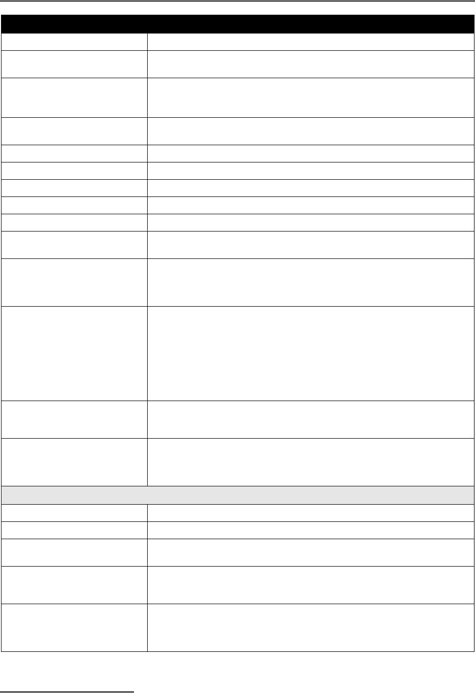
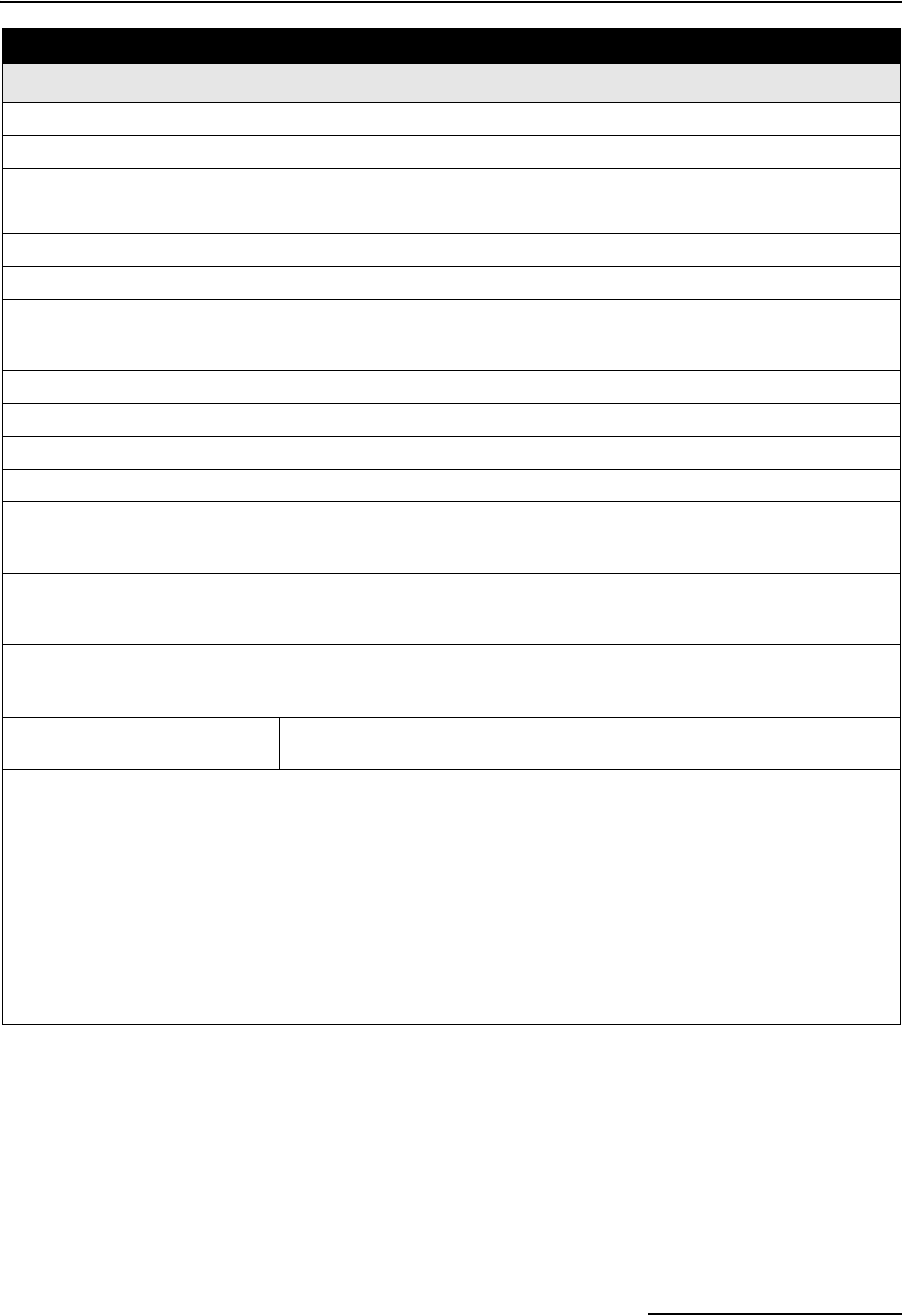
1-4 Connector Specifications . . . . . . . . . . . . . . . . . . . . . . . . . . . . . . . . . . . . . . . . . . . . 1-14
2-1 Distributor Arm Positions and Discharge Tube Lengths for Bottle Kits . . . . . . . 2-3
2-2 Selecting the Right Strainer . . . . . . . . . . . . . . . . . . . . . . . . . . . . . . . . . . . . . . . . . . 2-8
2-3 Connecting Isco Instruments to the Sampler . . . . . . . . . . . . . . . . . . . . . . . . . . . . 2-13
3-1 About the Keypad . . . . . . . . . . . . . . . . . . . . . . . . . . . . . . . . . . . . . . . . . . . . . . . . . . . 3-2
4-1 Standard Program: Sample Every 15 Minutes, One Sample Per Bottle . . . . . . . 4-2
4-2 Standard Program: Flow-Paced Sampling, Two Bottles Per Sample . . . . . . . . . . 4-3
4-3 Reports: Program Events, Source Codes, and Error Codes . . . . . . . . . . . . . . . . . 4-21
4-4 Programming Example With 730 Module Installed . . . . . . . . . . . . . . . . . . . . . . . 4-29
4-5 Programming Example With 750 Module Installed . . . . . . . . . . . . . . . . . . . . . . . 4-31
5-1 Selecting a Stored Extended Program . . . . . . . . . . . . . . . . . . . . . . . . . . . . . . . . . . 5-3
5-2 Storm Water Runoff Sampling . . . . . . . . . . . . . . . . . . . . . . . . . . . . . . . . . . . . . . . . 5-6

6712FR Refrigerated Sampler
Table of Contents
vii
5-3 Event Paced Sampling . . . . . . . . . . . . . . . . . . . . . . . . . . . . . . . . . . . . . . . . . . . . . . 5-13
5-4 Sampler Enable . . . . . . . . . . . . . . . . . . . . . . . . . . . . . . . . . . . . . . . . . . . . . . . . . . . 5-24
5-5 Serial Data Codes . . . . . . . . . . . . . . . . . . . . . . . . . . . . . . . . . . . . . . . . . . . . . . . . . . 5-33
7-1 6712 Remote Menu Commands . . . . . . . . . . . . . . . . . . . . . . . . . . . . . . . . . . . . . . . . 7-3
7-2 Serial Data Codes . . . . . . . . . . . . . . . . . . . . . . . . . . . . . . . . . . . . . . . . . . . . . . . . . . . 7-6
7-3 Remote Control of Sampler Keypad . . . . . . . . . . . . . . . . . . . . . . . . . . . . . . . . . . . . 7-8
7-4 6712 Remote Phone Commands . . . . . . . . . . . . . . . . . . . . . . . . . . . . . . . . . . . . . . . 7-9
8-1 Setting the Clock and Calendar . . . . . . . . . . . . . . . . . . . . . . . . . . . . . . . . . . . . . . . 8-5
8-2 Resetting the Pump Counter . . . . . . . . . . . . . . . . . . . . . . . . . . . . . . . . . . . . . . . . . . 8-6
8-3 Checking and Replacing the Internal Battery . . . . . . . . . . . . . . . . . . . . . . . . . . . . 8-6
C-1 Hazardous Gases . . . . . . . . . . . . . . . . . . . . . . . . . . . . . . . . . . . . . . . . . . . . . . . . . . . C-6

6712FR Refrigerated Sampler
Table of Contents
viii
1-1
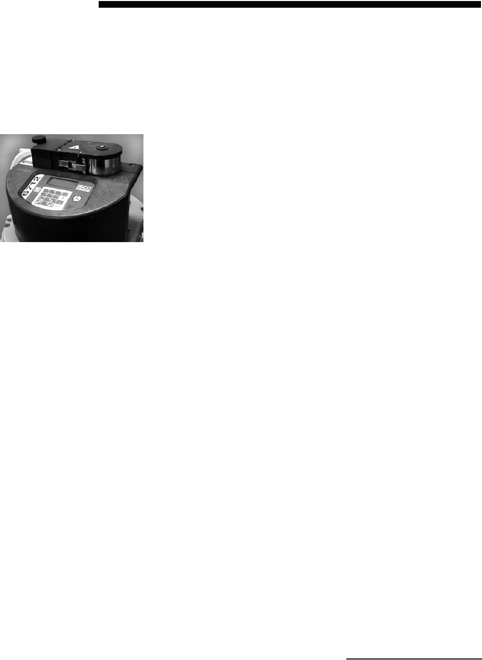
6712FR Refrigerated Sampler
Section 1 Introduction
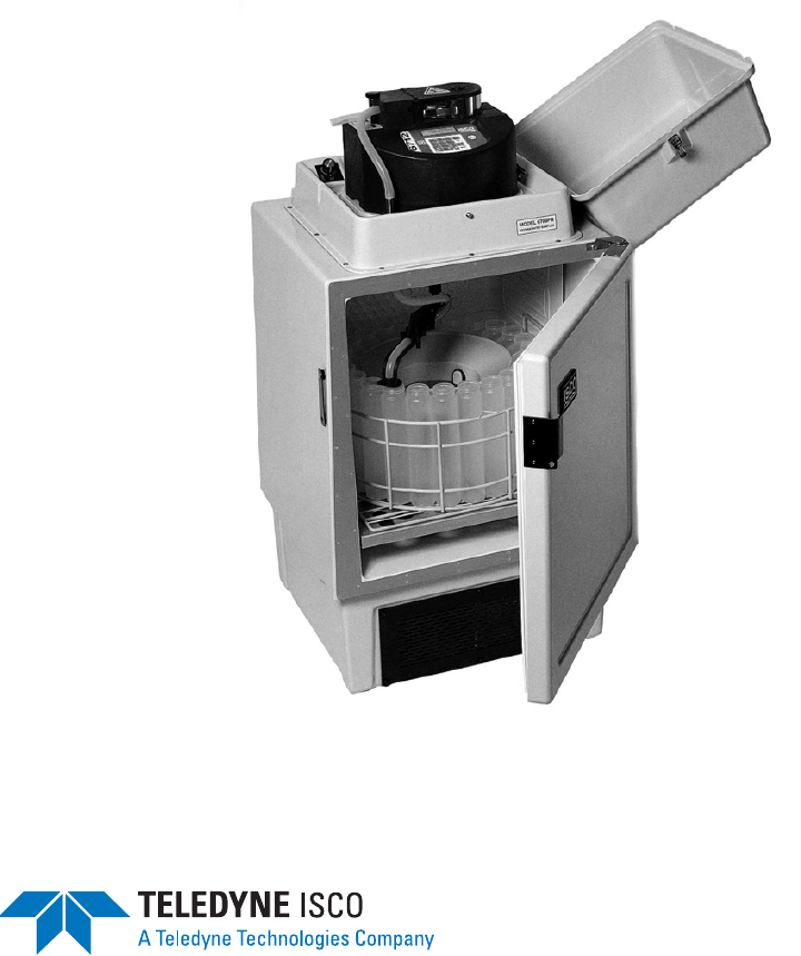
The 6712FR Refrigerated Sampler is an integral part of Teledyne
Isco’s comprehensive sampling system. The system includes the
6712FR and 6712SR Refrigerated Samplers, the 6712 Compact
Sampler, and the 6712 Standard Sampler.
The 6712FR is ideally suited for permanent installation in a wide
variety of indoor and outdoor environments. Constructed from
durable, corrosion resistant materials, the 6712FR withstands
the hostile environments of industrial and municipal monitoring
sites. However, do not install in locations where the refrigerator’s
lower compartment could become submerged.
The 6712FR accepts a variety of sequential and composite bottle
kits. Like all samplers in the 6712 series, it is compatible with a
variety of Isco instruments.
1.1 About This Manual This manual contains the information you will need to install,
program, operate, and maintain a 6712FR refrigerated sampler.
There are eight sections and five appendices:
•Section 1, Introduction lists the features and specifica-
tions of the 6712FR refrigerated sampler.
•Section 2, Installation/Preparation steps you through
installing the sampler and preparing it for use.
•Section 3, Getting Started describes features that are
common to both standard and extended programming
modes.
•Section 4, Standard Programming shows how to
program your sampler using standard programming
mode.
•Section 5, Extended Programming shows how to
program your sampler using extended programming
mode.
•Section 6, SDI-12 Sondes provides information on
setting up sondes to work with the 6712FR.
•Section 7, Remote Operation explains how the 6712
controller can be operated remotely from external
devices.
•Section 8, Maintenance covers the basic maintenance
required to keep your sampler in top operating
condition.
6712 Controller

6712FR Refrigerated Sampler
Section 1 Introduction
1-2
The appendices are:
• Appendix A, Menu Flowcharts
• Appendix B, Material Safety Data Sheets
• Appendix C, General Safety Procedures
• Appendix D, Replacement Parts
• Appendix E, Accessories List
1.2 About 700 Series
Modules
The bay on the controller’s side accepts any of Teledyne Isco’s 700
Series Modules. The 700 Series includes:
• 701 pH Parameter Module for monitoring pH and
temperature.
• 710 Ultrasonic Module for monitoring a flow stream’s
level and flow rate with an ultrasonic level sensor.
• 720 Submerged Probe Module for monitoring a flow
stream’s level and flow rate with a submerged probe.
• 730 Bubbler Flow Module for monitoring a flow stream’s
level and flow rate with a bubbler system.
• 750 Area Velocity Module for monitoring a flow stream’s
level, velocity, and flow rate.
• 780 4-20mA Input Module for interfacing to non-Isco
devices with 4 to 20 milliampere output signals.
The modules are optional accessories, and are not required for
operation. However, the modules offer a number of advantages:
they are an economical way to combine flow rate or parameter
monitoring with sampling, and you can program the samplers
and modules as a single unit. Finally, the samplers store the
readings in memory.
1.3 SDI-12 Sondes As an option, the sampler accepts up to 16 parameters from up to
ten sensors with SDI-12 addresses from 0 - 9 (refer to SDI-12
Sonde Readings, page 1-10, for specific parameters).
The data parameters used by the sensing device (sonde) and
recording device (sampler) must match. Certain vendors’ sondes
have enhanced commands that facilitate “plug and play” setup.
These Isco Ready sondes can tell the 6712FR what values they
have, their order, and units of measure. Other sondes can be
used, but require manual setup to identify proper data types for
each data value reported.
1.4 Memory to Store
Monitoring Data
The samplers contain enough memory to store five sampling pro-
grams, sampling data, Isco 700 Series Module readings, and
SDI-12 parameter readings. You can view the readings on your
sampler’s display.
You can also retrieve the readings and reports so the information
can be processed on a personal computer. Readings and reports
may be collected with a computer running Teledyne Isco’s
Flowlink™ software. Flowlink can download the information
through a direct connection, a modem connection (when the
sampler is equipped with the optional dial-out modem or con-
6712FR Refrigerated Sampler
Section 1 Introduction
1-3
nected to the optional digital cellular modem), or from a 581
Rapid Transfer Device (RTD). The RTD is a quick and simple
way to transfer the data from the field to your computer. Reports
are easily collected with Teledyne Isco’s Samplink software.
1.5 Pump Requirements The pump also requires a pump tube made specifically for the
6712 and 6700 Series samplers. These pump tubes are easily rec-
ognized by their blue alignment collars. The 6712 pump tubing is
the same as that for Teledyne Isco’s 6700 Series samplers, but
different from Teledyne Isco’s earlier model samplers, such as the
3700 Series. Other types of pump tubing will not work in
the 6712FR. Refer to Replacing the Pump Tube on page 8-9.
CAUTION
This sampler has a high performance pump. As with all such
pumps, it relies upon liquid to cool working components. If the
sampler is programmed to pump in the absence of liquid in
excess of 5 minutes, excessive heat buildup may damage the
paddles, rollers, and housing. Ensure that the liquid inlet is
completely immersed.
Table 1-1 6712FR Sampler Features
General Features
Top Cover • Protects pump, power source, and controller.
• Lockable latches.
Controller Only
(does not include refrigerator)
• Contains a rechargeable desiccant to prevent moisture damage to the
electronics, pump, and distributor systems.
• Control panel sloped 15 degrees for easy reading.
• Keys labeled with large, vivid icons.
• 80-character display (4 lines by 20 columns).
• Display has selectable backlight:
Always on or always off.
Timed, switching off when keypad is inactive for 60 seconds.
• Memory for program and data storage.
• Flash memory for easy software upgrades.
• NEMA 4X and 6 (IP67) ratings.
Refrigerator • The 6712FR requires 120 volts AC, 60 Hz, or optional 230 volts Ac, 50 Hz. A
built-in 12 volt DC power converter powers the controller.
• The power supply and solid state thermostat are sealed inside the refrigerator’s
base. However, electrical connections for the fan and compressor are not
sealed.
• A forced air condensing coil and front ventilation let you place the unit close to a
wall or in a corner.
• The oversized wrap-around evaporator plate cools the sampling compartment
quickly and efficiently. Heaters on the plate let the sampler continue to operate
in cold temperatures. The evaporator plate is self-defrosting.
• Food-grade ABS plastic interior will not support bacterial growth or leach
plasticizers into the sample.

6712FR Refrigerated Sampler
Section 1 Introduction
1-4
Adjustable
Distributor Arm • A single distributor arm adjusts quickly to fit all bottle kits. Easily removed for
composite sampling.
Discharge Tube and Support
Spring • Routes sample liquid from pump tube, through distributor arm to sample bottle.
Composite Tube Guide for Com-
posite Sampling • Keeps discharge tube in place over composite bottles.
Compatible
Isco Products • 581 Rapid Transfer Device
• 1640 Liquid Level Actuator
• 2100 Series Flow Modules
• 674 Rain Gauge
• 700 Series Modules
• 4100 Series Flow Loggers
• SDI-12 Sondes
• 4200 Series Flow Meters
• Refrigerator Temperature Sensor
• Flowlink, Samplink
Real-Time Displays As the sampler runs a sampling program, it displays the program’s status. The
status display may include such information as the time of the next sample, the
number of the next bottle, or whether the sampler is disabled or stopped. If the
sampler encounters an error while running the program, it displays a message
alerting you to the problem.
Programming for Modules Program the modules from the sampler’s control panel. The module’s program
settings become part of the sampling program.
Setup for SDI-12 Sondes Calibrate and program SDI-12 sondes from the sampler’s control panel. The pro-
gram settings become part of the sampling program. See Section 6.
Memory for Stored Programs
and Readings 512 kilobytes of battery-backed RAM (Random Access Memory), to store:
• Five sampling programs.
• A sampling report from the most recently run program. It records as many as
1000 sampling events; events can be the program start time, enable time,
sample event information, etc.
• 700 Series module readings. The readings can be: level, flow rate, velocity, pH,
temperature, or the data collected by the 4-20 mA module.
• Rain gauge and refrigerator temperature readings.
• SDI-12 sonde readings.
Five Reports Available • The Program Settings report, listing current program settings.
• The Sampling Results report, listing the events occurring during the program.
• The Combined Results report, combining sampling events with readings from a
rain gauge, module, or SDI -12 sonde.
• The Module Summary report, summarizing flow rate or parameter readings.
• The Rainfall Summary report, listing a summary of rainfall readings.
Serial Data Output • ASCII data output from the interrogator port.
Units of Measure A variety of metric and English units of measure for length, flow rate, flow vol-
ume, and temperature.
External Sampler Enable Isco flow meters and flow loggers have a programmable sampler enable feature
that lets them send an electronic signal to a 6712FR that enables (starts) or dis-
ables (stops) a running sampling program.
Dual Sampler Mode Dual Sampler Mode operates two samplers.
Table 1-1 6712FR Sampler Features (Continued)
6712FR Refrigerated Sampler
Section 1 Introduction
1-5
Command Driven Operation • Operate sampler functions using RS-232 communications.
Warning Messages • Pump Tube Warning. The 6712FR displays a warning to inspect the tube.
• Internal Battery Warning. From the Maintenance screen, the 6712FR displays a
warning when it is time to replace the internal battery. The internal battery
preserves stored data when the 6712FR is without external power.
Optional Dialout Modem The 6712 controller can be ordered with a factory-installed 2400 baud dialout
modem. With the modem you can:
• connect to the sampler and download data using Flowlink software.
• program the sampler to call a contact list when an “alarm” condition exists.
• use the Remote Commands to control the sampler’s operation from a remote
location.
On-Line Help Notes When programming the sampler, press the [?] (Help) key for a brief help note. All
help topics appear in the index.
Two Programming Levels Standard programming lets you set up typical sampling programs quickly.
Extended programming includes all features available in standard programming
plus additional features.
Sample Delivery System Features
Peristaltic Pump •Benefits: Liquid moves continuously under pumped flow. The pump has no
metering chambers or gravity fed internal tubing to trap sediment or residual
liquid. Sample liquid contacts only the strainer, suction line, tube coupling,
pump tube, bulkhead fitting, and sample bottles.
LD90 Liquid Detector •Non wetted Detection: Sample liquid never touches the detector.
Two Line Purges in Sampling
Cycle The sampling cycle always includes a pre-sample purge and post-sample purge
that clears the suction line of residual liquid.
Easy Grab Samples Simply disconnect the pump tube from the bulkhead fitting on the center section,
and place the pump tube over your sample container.
Vinyl and PTFE
Suction Lines •3/8-inch ID (Inside Diameter) vinyl line.
•3/8-inch ID PTFE lined with polyethylene jacket.
Standard Programming Features
Pacing •Uniform Time Pacing: Sampling at regular time intervals.
•Flow Pacing: Sampling at regular flow-volume intervals.
Distribution Methods •Composite: Samples deposited in a single large bottle.
•Sequential: Only one sample placed in each bottle.
•Samples Per Bottle: Multiple samples placed in each bottle.
•Bottles Per Sample: One sample deposited in multiple bottles.
Three Flexible
Start-Time Settings •Start Immediately: Starts the sampling program immediately.
•Delayed Start: Starts the sampling program after a user-definable delay of 1 to
999 minutes.
•Clock Time: Starts the sampling program at a user-definable time on one or
more days of the week.
Table 1-1 6712FR Sampler Features (Continued)

6712FR Refrigerated Sampler
Section 1 Introduction
1-6
Option for a Continuous Run-
ning Program •Continuous Sampling: When sample bottles are regularly replaced, the
sample distribution can restart with the first bottle set after the last bottle set is
filled, without interrupting the running program.
Extended Programming Features
Pacing •Uniform Time Pacing: Sampling at regular time intervals.
•Nonuniform Time Pacing: Sampling at irregular time intervals.
•Random Interval Pacing: Sampling at unique random time intervals generated
by the controller.
•Flow Pacing: Sampling at regular flow-volume intervals.
•Event Pacing: Sampling each time a user-definable event occurs.
Flow Proportional
Sample Volumes Allows for sample sizes to be based on flow. (This option is available only with
uniform time pacing.)
Distribution Methods •Composite: Samples deposited in a single large bottle.
•Sequential: Only one sample placed in each bottle.
•Samples Per Bottle: Multiple samples placed in each bottle
•Bottles Per Sample: One sample deposited in multiple bottles
•Multiple Bottle Compositing: A combination of samples per bottle and bottles
per sample distribution methods.
•Time Switched Bottles or Bottle sets: Control the sample distribution using
clock times.
Programmable Sampler Enable A 6712FR sampler can be programmed to enable or disable a running sampling
program when readings received from a connected rain gauge, module, or
SDI-12 Sonde meet certain conditions.
Pauses and Resumes Create intermittent sampling schedules.
Two-Part Programming Two-part programming lets you set up a sampling program that divides the bot-
tles into two groups, filling each group according to separate pacing, distribution,
sampler enable, and pause and resume settings. This is ideal for storm-water
run-off sampling.
Auto Suction Head or Fixed Suc-
tion Head The suction head, is the vertical distance from the flow stream to the liquid detec-
tor. Extended programming has two settings.
•Auto-Suction Head: The head is automatically determined.
•Fixed Suction Head: A user-definable measurement for the head.
Suction Line Rinses Program setting for the number of times (0 to 3) that the 6712 rinses the suction
line before drawing a sample.
Sampling Retries Program setting for the number of times (0 to 3) that the 6712 attempts to sample
if it fails to deliver the entire sample volume.
Three Flexible
Start Time Settings •Run Immediately: Starts the sampling program immediately.
•Delayed Start: Starts the sampling program after a user-definable delay of 1 to
999 minutes.
•Clock Time: Starts the sampling program at a user-definable time on one or
more days of the week.
Option for a Continuous Run-
ning Program Continuous Sampling: When sample bottles are regularly replaced, the sample
distribution can restart with the first bottle set after the last bottle set is filled,
without interrupting the running program.
Table 1-1 6712FR Sampler Features (Continued)
6712FR Refrigerated Sampler
Section 1 Introduction
1-7
Table 1-2 6712FR Sampler Construction Materials
Item Material
Top Cover and
Refrigerator Body
Fiberglass reinforced plastic with ultraviolet-resistant gel coat.
Plastic Retaining Rings ABS (Acrylonitrile Butadiene Styrene) plastic
Controller Case
Distributor Arm
Noryl®
Distributor Arm Nut
Pump Rollers
Delrin®
Control Panel
Connector Labels
Polyester
Distributor Shaft
Pump Shaft
Pump Paddles
Pump Band
Bulkhead Fitting
Latches
Metal Retaining Rings
Stainless steel
Refrigeration Tubing
Protection
Protected with polyester tubing or phenolic resin.
Condenser Protection Powder coated with polyester.
Evaporator Protection Powder coated with food-grade epoxy.
Refrigerant R134a (1,1,1,2-tetrafluoroethane CH2FCF3)
Insulation Polyurethane
Amphenol Connectors Cadmium Plated Aluminum
Table 1-3 Technical Specifications for the 6712FR Refrigerated Sampler
General Notes:
1. All weights may vary ±1 lb (±1/2 kg).
2. All dimensions may vary ±1/4 inch (±0.64 cm).
3. Sample delivery specifications valid for the following conditions and ranges, unless otherwise stated: 75°F (24°C)
ambient, sample liquid–tap water at 50 to 80°F (10 to 27°C), sample volumes from 50 ml to 1000 ml, suction line
lengths of 25 ft (7.6 m) or less, suction heads from 1 to 20 ft (0.3 to 6.1 m), atmospheric pressure between 29.92 and
31.89 inHg (760 and 810 mmHg), and a power source of an Isco High Capacity Power Pack at 12.5 volts DC no load
output.
6712 Controller, Pump, and Tubing: Mechanical Specifications
Weight of Controller: Controller only: 13.0 lbs (5.9 kg)
With pump tube: 13.2 lbs (6.0 kg)
Weight of Nickel Cadmium Bat-
tery: 4.3 lbs (2.0 kg)
Weight of Lead Acid Battery: 5.7 lbs (2.6 kg)
6712FR Refrigerated Sampler
Section 1 Introduction
1-8
Weight of Power Pack: 6.0 lbs (2.7 kg)
Weight of Battery Backed Power
Pack: 6.6 lbs (3.0 kg)
Controller Dimensions: Length: 10.3 in (26.0 cm)
Width: 12.5 in (31.7 cm)
Height: 10 in (25.4 cm)
Temperature Ranges: Operational: 32 to 120 °F (0 to 49 °C)
Storage: 0 to 140 °F (–18 to 60 °C)
Maximum Altitude: 2,000 Meters
Installation Category: II
Pollution Degree: 2
Humidity: 95% RH Maximum
Enclosure: NEMA 4X and 6 Pump: IP17 Enclosure: IP67
Typical Delivered
Volume Accuracy: (The ability to deliver the programmed sample volume.)
±10 ml or ±10% of programmed value, whichever is greater.
Typical Repeatability: (The ability to repeat the delivered volume for a set of samples collected under
the same conditions.)
±5 ml or ±5% of the average of the maximum and minimum sample volume in a
sample set, whichever is greater, at lifts up to 25 feet.
Typical Pump Flow Rate and
Line Transport Velocity: Suction Head Flow Rate Line Transport Velocity
3 feet 3.9 liters per minute 3.0 ft/s (0.91 m/s)
5 feet 3.9 liters per minute 3.0 ft/s (0.90 m/s)
10 feet 3.7 liters per minute 2.9 ft/s (0.87 m/s)
15 feet 3.6 liters per minute 2.7 ft/s (0.83 m/s)
20 feet 3.3 liters per minute 2.5 ft/s (0.77 m/s)
23 feet 3.1 liters per minute 2.3 ft/s (0.71 m/s)
25 feet 2.8 liters per minute 2.2 ft/s (0.66 m/s)
Maximum Suction Head: (The maximum suction head is the vertical height at which a sample can be
taken.)
28 ft (8.5 m) at 30 inHg (762 mmHg)
Pump Tube Life: Tube life may vary depending on the abrasiveness of the sample liquid.
Recommended maximum 1,000,000 pump counts. This equates to 912 stan-
dard samples. A standard sample is 200 ml at 5 ft (1.5 m) suction head using a
10 ft (3 m) vinyl suction line.
6712 Controller: Electrical Specifications
Controller Internal Battery: 5 years minimum (maintains internal logic, program settings & stored data)
Real Time Clock Accuracy: 1 minute per month
Program Memory: Nonvolatile programmable Flash.
Can be field updated via interrogator connector.
Sampler Power Requirements: Nominal: 12 volts DC supplied by the refrigerator
Operational: 11 to 13 Volts DC
Absolute Maximum: 14.4 Volts DC
Power Pack Requirements:
Use only Isco-made power
packs certified by UL.
(P/N 60-1684-088)
120VAC ±12VAC, 60 Hz., 1.0 Amp.
Note: This is the only version certified by UL. The line cord (mains
connect cable) is the “Disconnect Device.”
Table 1-3 Technical Specifications for the 6712FR Refrigerated Sampler (Continued)
6712FR Refrigerated Sampler
Section 1 Introduction
1-9
Power Consumptiona
6712 Controller in Standby 10 mA
Average Current of Accessories
Controller Display Backlight 228 mA
701 pH Moduleb11 mA
710 Ultrasonic Moduleb11 mA
720 Submerged Probe Moduleb11 mA
730 Bubbler Moduleb
— at 2 ft of liquid level 24 mA
— at 10 ft of liquid level 31 mA
750 Area Velocity Moduleb12 mA
780 4-20 mA Moduleb10 mA
YSI 600 with pH, DO, Conductivity, and Temperatureb11 mA
Programmable Analog 4-20 mA Output Optionc124 mA
CDMA cellular telephone modem
— standby current 35 mA
— current while communicating 150 mA
GSM cellular telephone modem
— standby current 62 mA
— current while communicating 230 mA
a. Current ratings when input power is 12.5 VDC and ambient temperature is 77 °F (25 °C)
b. Average current when programmed to take readings at 15 minute intervals.
c. Rating for three outputs.
Sampler Only
Operating Current: Approximately 30 mA based on 200 ml sample every hour, 10 ft (3 m) suction
line, and 5 ft (1.5 m) suction head.
Isco External Battery Capacity: Number of Complete Standard Sampling Routines
Nickel-Cadmium Battery Lead-Acid Battery
Sampler Only: 6 9
Sampler with pH Module: 6 9
Sampler with Ultrasonic Module: 6 9
Sampler with Submerged Probe Module: 6 9
Sampler with Bubbler Module (1-2 ft head): 3 5
Sampler with Area Velocity Module: 4 6
Sampler with 4-20 mA Module: 6 9
A Standard Sampling Routine is a 200 ml sample taken every hour in 24 bottle mode, with a 10 foot (3 m) vinyl suc-
tion line at 5 feet (1.5 m) of head. The module is set to take a reading every 15 minutes.
Table 1-3 Technical Specifications for the 6712FR Refrigerated Sampler (Continued)

6712FR Refrigerated Sampler
Section 1 Introduction
1-10
6712 Controller: Software Specifications
Suction Line: Programmable 3 to 99 ft (1 to 30 m) lengths of:
•3/8" (0.95 cm) I.D. Vinyl
•3/8" (0.95 cm) I.D. PTFE-lined with polyethylene jacket
Sample Frequency: • From 1 minute to 99 hours and 59 minutes in 1 minute increments between
consecutive samples.
• Nonuniform times in minute intervals or clock time
• Random time intervals between consecutive samples
• From 1 to 9,999 flow pulses in single-pulse intervals
• Flow paced in volume with attachable flow module
Rainfall Reading Units: Inches or millimeters
Module Readings:pH 8 bits representing pH 0.1 pH storage resolution
16 bits representing temp. 0.1 °C storage resolution
Ultrasonic 16 bits representing level 0.0001 m storage resolution
Submerged Probe 16 bits representing level 0.0001 m storage resolution
Bubbler 16 bits representing level 0.0001 m storage resolution
Area Velocity 16 bits representing level 0.0001 m storage resolution
16 bits representing velocity 0.001 ft/s storage resolution
4–20 mA 16 bits representing percent 0.1% storage resolution
16 bits representing level
32 bits representing flow
SDI-12 Sonde Readings: Parameter Range Resolution Storage Bytes
Temperature -40 - 100 °C 0.1 °C 2
Conductivity 0 - 100 mS/cm 0.01 mS/cm 2
Specific Conductance 0 - 100 mS/cm 0.01 mS/cm 2
Total Dissolved Solids 0 - 90 g/l 0.01 g/l 2
Salinity 0 - 70 ppt 0.1 ppt 2
Dissolved Oxygen 0 - 20 mg/l 0.1 mg/l 1
pH 0 - 14 0.1 1
ORP -999 - 999 mv 0.1 mv 2
Level 0 - 6.5279 m 0.0001 m 2
Ammonium-Nitrogen 0 - 200 mgN/l 0.1 mgN/l 2
Ammonia-Nitrogen 0 - 200 mgN/l 0.1 mgN/l 2
Nitrate-Nitrogen 0 - 200mgN/l 0.1 mgN/l 2
Turbidity 0 - 5000 NTU 0.1 NTU 2
Chloride 0 - 1000 mg/l 0.1 mg/l 2
Chlorophyll 0-400 ug/l 0.1 ug/l 2
Other -99999.0-99999.0 0.0001 4
Table 1-3 Technical Specifications for the 6712FR Refrigerated Sampler (Continued)

6712FR Refrigerated Sampler
Section 1 Introduction
1-11
Module Reading Conversions: • Level and 4–20 mA readings converted to flow rate units:
gallons per second gallons per minute
million gallons per day cubic feet per second
cubic meters per second cubic meters per hour
cubic meters per day liters per second
• Velocity units:
feet per second meters per second
• Totalized flow units:
gallons million gallons
cubic feet cubic meters
liters
• Devices supported in flow conversion:
Weirs: V-notch; 22.5, 30, 45, 60, 90, and 120 degrees
Rectangular; with and without end contractions
Cipoletti.
Flumes:Parshall; 1", 2", 3", 6", 9", 1.5', 2', 3', 4', 5', 6', 8', 10', 12'
Palmer-Bowlus; 4", 6", 8", 12", 15", 18", 21", 24", 27", 30", 48"
Trapezoidal; LG 60 V, 2" 45 WSC, 12" 45 SRCRC
H; 0.5', 0.75', 1', 1.5', 2', 2.5', 3', 4.5'
Equation: Q = a x Hb+c x Hd
where:
Q = flow
H = head
a,b,c, and d = entered values
Manning Formula: Round, U-channel, Rectangular, Trapezoidal
Area Velocity: Round, U-channel, Rectangular, Trapezoidal
Data Points: 50 level-flow rate points, 50 level-area points
Refrigerator Temperature Sen-
sor Optional sensor and 5 ft (1.55 m) cable to record temperature readings.
Intended for use with fiberglass refrigerated (FR) samplers.
Range: -40.0 °C to 100 °C
Accuracy specification: ±0.3 °C over a range of 0.0 to 10.0 °C.
Reading data is 2 bytes, with a storage resolution of 0.1 °C.
6712FR Refrigerated Sampler: Physical Specifications
Dimensions: Height: Top cover closed: 49.25 in (125 cm)
Top cover open: 59.25 in (150.5 cm)
Width: 26 in (66 cm)
Depth: 26 in (66 cm)
Bottle Configurations: • 24 wedge polypropylene bottles, 1,000 ml
• 24 round glass bottles, 350 ml
• 12 wedge polyethylene bottles, 2.5 liters
• 8 round polyethylene bottles, 2.0 liters
• 8 round glass bottles, 1.8 liters
• 2 rectangular polyethylene bottles, 7.5 liters (2 gal)
• 2 round glass bottles, 9.4 liters (2.5 gal)
• 1 round polyethylene bottle, 9.4 liters (2.5 gal)
• 1 round glass bottle, 9.4 liters (2.5 gal)
• 1 round polyethylene bottle, 15 liters (4 gal)
• 1 round polyethylene bottle, 20.5 liters (5.5 gal)
• 1 round glass bottle, 18.5 liters (5.0 gal)
Table 1-3 Technical Specifications for the 6712FR Refrigerated Sampler (Continued)

6712FR Refrigerated Sampler
Section 1 Introduction
1-12
Dry Weight: 145 lbs (66 kg) Refrigerator only, no controller or bottle configuration
160 lbs (73 kg) Includes refrigerator, controller, top cover, center section, tub,
pump tube, distributor shaft extension, distributor arm and nut, and discharge
tube for the 24 plastic bottle configuration.
Dry Weight With: 24 plastic bottles, rack, hold down, no caps 175 lbs(79 kg)
24 glass bottles, rack, expander ring, no caps 195 lbs(88 kg)
12 plastic bottles, rack, hold down, no caps 175 lbs(79 kg)
8 plastic bottles, rack, adaptor, no caps 170 lbs(77 kg)
8 glass bottles, rack, adaptor, no caps 180 lbs(82 kg)
2 plastic bottles, rack, no caps 175 lbs(79 kg)
2 glass bottles, rack, no caps 165 lbs(75 kg)
1-9.4 l plastic bottle and cap, no distributor arm or nut165 lbs(75 kg)
1-9.4 l glass bottle and cap, no distributor arm or nut 170 lbs(77 kg)
1-15.0 l plastic bottle and cap, no distributor arm or nut165 lbs(75
kg)
1-20.5 l plastic bottle and cap, no distributor arm or nut165 lbs(75
kg)
1-18.5 l glass bottle and cap, no distributor arm or nut 170 lbs(77 kg)
Filled Bottle Weight: 24 plastic bottles 101 lbs(46 kg)
24 glass bottles 104 lbs(48 kg)
12 plastic bottles 89 lbs (41 kg)
12 glass bottles 95 lbs (43 kg)
8 plastic bottles 84 lbs (38 kg)
8 glass bottles 90 lbs (41 kg)
4 plastic bottles 98 lbs (45 kg)
4 glass bottles 104 lbs(48 kg)
1 plastic bottle 90 lbs (41 kg)
1 glass bottle 94 lbs (43 kg)
Average Thermal
Resistance Factor: R-16
The average R-value for a complete FR refrigerator not running
Recovery time 5 minutes
Recovery time is the time for the internal air temperature to return to 39°F (4°C) after the door has been opened for
one minute. The empty refrigerator is running and set at 39°F (4°C). The door is opened at least 4 minutes after the
compressor has turned on. Ambient air temperature is 75°F (24°C).
Thermostat Set point range: 32° to 46°F (0° to 8°C)
Set point accuracy: ±1.8°F (±1°C) at 39°F (4°C)
[With an ambient air temperature of 75°F (24°C)]
Temperature Ranges Operational: -20° to 120°F (-29° to 49°C)
Storage: 0° to 140°F (-18° to 60°C)
Environment Rain and spray resistant, but not watertight. Do not install in locations where the
refrigerator’s lower compartment could become submerged.
Electrical Power Requirements: 120 Volts, 60 Hz 230 Volts, 50 Hz
(optional)
Running current: 3.5 amp 1.75 amp
Starting current: 17 amp 8.5 amp
Stalled Compressor current:21 amp 10.5 amp
(maximum)
Table 1-3 Technical Specifications for the 6712FR Refrigerated Sampler (Continued)

6712FR Refrigerated Sampler
Section 1 Introduction
1-13
Heater Capacity 60 watts
Compressor 1/5 HP (150W) Tecumseh compressor
Compressor Protection Temperature safety cutout that will disengage the compressor if the
compressor reaches 221°F (105°C)
Refrigerant R134a, 8 ounce (0.21 kg) charge
Pressure High side: 165 to 215 psig (1.14 to 1.48 MPa)
Low side: 2 to 10 psig (13.8 to 69 kPa)
Table 1-3 Technical Specifications for the 6712FR Refrigerated Sampler (Continued)
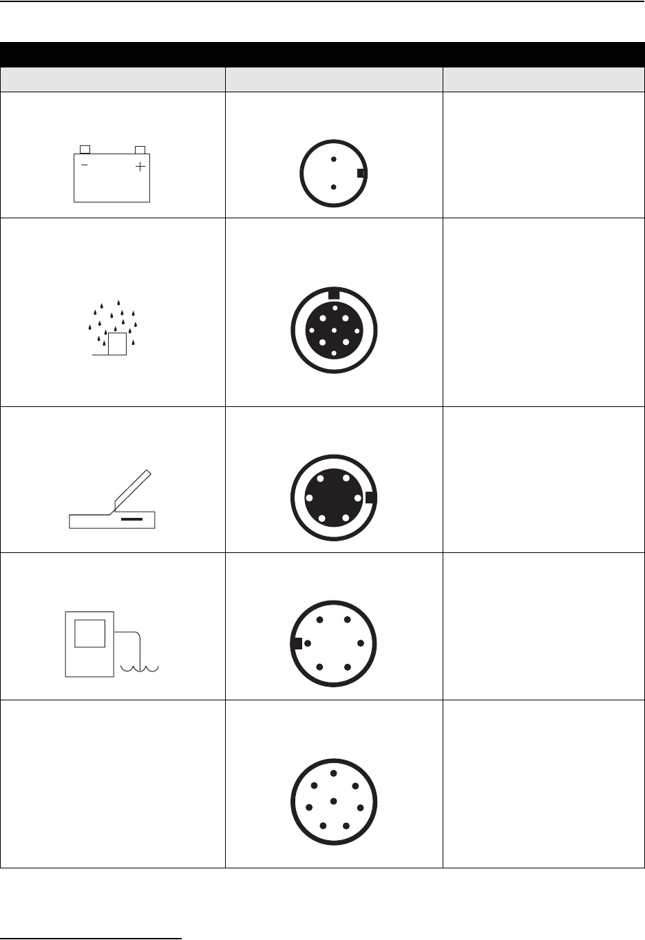
6712FR Refrigerated Sampler
Section 1 Introduction
1-14
Table 1-4 Connector Specifications
Connector Icon Pin Location Diagram Pin Function
POWER SOURCE 2-PIN MALE, SEALED A Ground
B +12 volts DC
RAIN GAUGE 9-PIN FEMALE, SEALED
A +12 volts DC
B Ground
C Programmable I/O1 pin
D Rain gauge input
E Not Connected
F SDI-12 Data
G Not Connected
H Programmable I/O2 pin
I Programmable I/O3 pin
INTERROGATOR 6-PIN FEMALE, SEALED A Switched +12 volts DC
B Ground
C Connection Sense
D Transmit
E Receive
F NC
FLOW METER 6-PIN MALE, SEALED A +12 volts DC
B Ground
C Flow Pulses In
D Bottle Number Out
Dual Sampler Out
E Event Mark Out
F Inhibit In
MODULE
(IN MODULE BAY)
8-PIN MALE, SEALED
1 NC
2 +12 volts DC
3 Ground
4 Module Sense
5 Receive
6 Transmit
7 Clock
8 Control
AB
A
BC
D
F
G
H
E
I
A
B
C
D
E
F
A
B
C
D
E
F
1
2
3
45
6
7
8

2-1
6712FR Refrigerated Sampler
Section 2 Installation/Preparation
2.1 Preparing the Sampler The 6712FR is shipped to you with the controller mounted on the
refrigerator and a distributor shaft extension installed. Use
Figure 2-1 for reference when removing the controller. You must
remove the controller when:
• The internal desiccant needs recharging, the internal
battery needs to be replaced or when the controller
needs repair.
• You install a different bottle kit.
Each bottle kit has its own extension so that the distributor arm
is positioned at the right distance above the bottles. You must
remove the controller to replace the extension.
2.1.1 Installing the
Distributor Shaft
Extension
1. Install the extension before mounting the controller on the
refrigerator.
2. Select the extension of the correct length for the bottle kit,
and screw it on the distributor shaft. Secure it with the set
screw. See Figure 2-1.
BE SURE THE SET SCREW IS TIGHTENED INTO THE
DISTRIBUTOR SHAFT’S KEY. YOU MAY HAVE TO
LOOSEN THE EXTENSION SLIGHTLY AND ADJUST ITS
POSITION.
2.1.2 Mounting the
Controller
1. Install the four mounting rods into the bosses on the bot-
tom of the case.
2. Fit the mounting rods through the four holes drilled in the
top of the refrigerator.
3. Slip a washer on each rod and secure the controller by
tightening the wing nuts.
4. Install the distributor arm and discharge tube.
5. Thread the stop arm into the hole in the side of the exten-
sion. Be sure the stop arm is directly above the distributor
arm.
6. Connect the power cable to the controller.
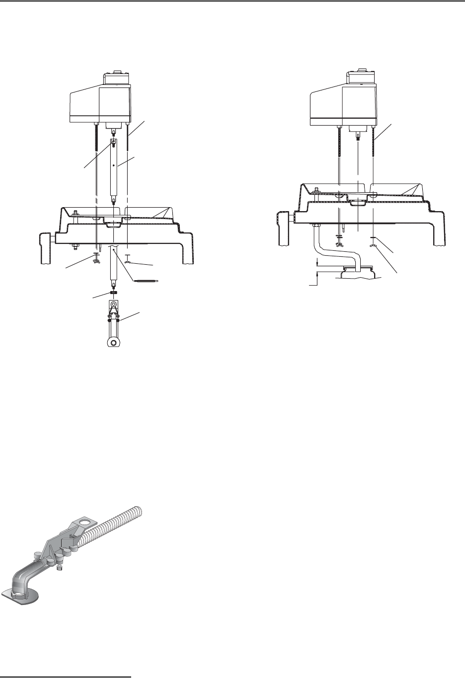
6712FR Refrigerated Sampler
Section 2 Installation/Preparation
2-2
Figure 2-1 Mounting the Controller
2.1.3 Installing the
Distributor Arm and
Discharge Tube
The distributor arm is adjustable so that you can position the
discharge tube over the bottles of each kit. Each bottle kit also
uses a discharge tube of a specific length. Table 2-1 lists the
correct discharge tube lengths for each bottle kit. If you are using
bulk tubing to cut your own tubes, cut the ends of the tube
square, not at an angle, and cut the length accurately.
The two-piece distributor arm has four positions, marked on the
underside with the letters A, B, C, and D. Adjust the arm to the
correct position for the bottle kit being used. Table 2-1 shows the
correct position for each kit. Thread the discharge tube through
the spring and arm so that the tube protrudes from the arm 1/16
to 1/8 inch. If too much tube protrudes from the arm it can catch
on bottles and jam the distributor arm.
Attach the arm to the distributor shaft extension. Secure the arm
to the extension with the black plastic nut. Slide the free end of
the discharge tube onto the bulkhead fitting. After installing the
distributor arm and discharge tube, run the distributor to each
bottle position to ensure proper installation.
Multiple-Bottle Sampling
Wing Nut
Stop Arm
Distributor arm
Assembly
1/4-20 Set Screw
Distributor arm
Nut
Distributor Shaft
Extension
Mounting Rod
Flat Washer
Composite Sampling
Mounting Rod
Flat Washer
Wing Nut
below neck of bottle.
End of discharge tube
Distributor Arm
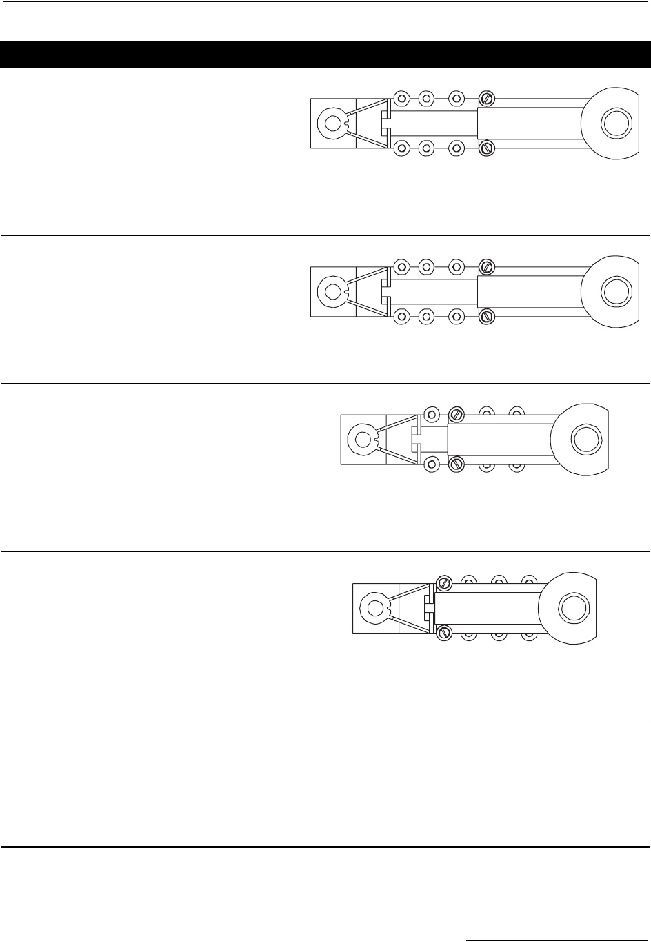
6712FR Refrigerated Sampler
Section 2 Installation/Preparation
2-3
Table 2-1 Distributor Arm Positions and Discharge Tube Lengths for Bottle Kits
24-Bottle Kits
1000-milliliter polypropylene bottles
350-milliliter glass bottles
Distributor Arm Position: D
Discharge Tube: 60-9003-279
Discharge Tube Length: 20 inches (50.8 cm)
Distributor Shaft: 60-9003-273
Distributor Shaft Extension: 811/16 inches (22.0 cm)
12-Bottle Kits
2.5 liter polyethylene bottles
Distributor Arm Position: D
Discharge Tube: 60-9003-279
Discharge Tube Length: 20 inches (50.8 cm)
Distributor Shaft: 60-9003-273
Distributor Shaft Extension: 811/16 inches (22.0 cm)
8-Bottle Kits
1.8 liter glass bottles
2.0 liter polyethylene bottles
Distributor Arm Position: B
Discharge Tube: 60-9003-279
Discharge Tube Length: 20 inches (50.8 cm)
Distributor Shaft: 60-9003-274
Distributor Shaft Extension: 101/2 inches (26.7 cm)
2-Bottle Kits
9.4 liter (21/2 gallon) glass bottles
7.5 liter (2 gallon) polyethylene bottles
Distributor Arm Position: A
Discharge Tube: 60-9003-283
Discharge Tube Length: 16 inches (40.6 cm)
Distributor Shaft: 60-9003-275
Distributor Shaft Extension: 6 inches (15.2 cm)
Composite BottlesDischarge TubeDischarge Tube Length
9.4 liter (21/2 gallon) glass bottle60-9003-262171/4 in (43.8 cm)
9.4 liter (21/2 gallon) polyethylene bottle60-9003-262171/4 in (43.8 cm)
15.0 liter (4 gallon) polyethylene bottle60-9003-264161/2 in (41.9 cm)
18.5 liter (5 gallon) glass bottle60-9003-266153/4 in (40 cm)
20.0 liter (51/2 gallon) polyethylene bottle60-9003-266153/4 in (40 cm)

6712FR Refrigerated Sampler
Section 2 Installation/Preparation
2-4
2.2 Installing Bottle Kits Teledyne Isco ships the refrigerator from the factory with the
sample bottles in place. When using the sampler for the first
time, you will only need to remove the bottle lids. When
installing cleaned bottles or a new kit, keep these guidelines in
mind:
• Do not mix glass and plastic bottles together.
• Install all bottles to insure that they remain in place.
• Align the racks correctly. If the racks are misaligned, the
sampler may miss the bottle mouth, or the sampler will
deposit samples in the “wrong” bottle.
Each time you change from one size bottle to another, you must
adjust the length of the distributor arm, install a discharge tube
of the correct length, and possibly install a different distributor
shaft extension.
Each time you install a bottle kit, check the program settings for
the number of bottles and bottle volumes. Also rotate the dis-
tributor arm to each bottle position to ensure the arm is correctly
positioned over each bottle. Use the controller to move the arm.
2.2.1 Installing Racks Install the bottle rack with bottles by sliding it into the cooling
compartment until the rack drops over the two semicircular
ramps which hold it in place (Figure 2-2).
The five posts and two ramps which position the rack under the
distributor arm are adjusted at the factory. When you change
bottle kits, you may need to readjust the stops and ramps and
install a different distributor arm extension. Figures 2-3 and 2-4
show you how to install the bottle kits.
Check the kit’s alignment by rotating the distributor arm. Do
not rotate the distributor manually. Moving the arm man-
ually damages the distributor drive. If you see any mis-
alignment, adjust the posts and ramps until the discharge tube
at the end of the arm stops over each bottle.
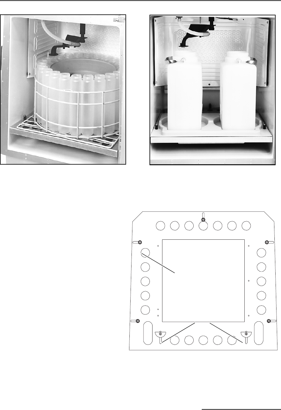
6712FR Refrigerated Sampler
Section 2 Installation/Preparation
2-5
Figure 2-2 Installing the Bottle Racks
Figure 2-3 Installing the 24-bottle, 12-bottle, and 8-bottle Kits
24-Bottle Kit
1000-milliliter polypropylene bottles.
2-Bottle Kit
(Requires a locating base.)
Stop
(1 of 5)
Ramps
Install the distributor shaft extension.
Use the 811/16-inch extension for the 12-
and 24-bottle kits. Use the 101
/2-inch ex-
tension for the 8-bottle kit. The instruc-
tions on page 2-1 show you how to remove
the controller and replace the extensions
for each bottle kit.
Next, adjust the distributor arm to position
D for the 12-bottle and 24-bottle kits, or to
position B for the 8-bottle kit. Install the
arm and stop. See Installing the Distribu-
tor Arm and Discharge Tube on page 2-2.
Slide the rack, with bottles installed onto
the mounting plate. Adjust the stops and
ramps on the plate so that the rack is cen-
tered and held firmly on the plate.
Finally, position the arm over each bottle.
If the arm does not stop over each bottle,
readjust the rack.
NEVER MANUALLY ROTATE
THE DISTRIBUTOR ARM.
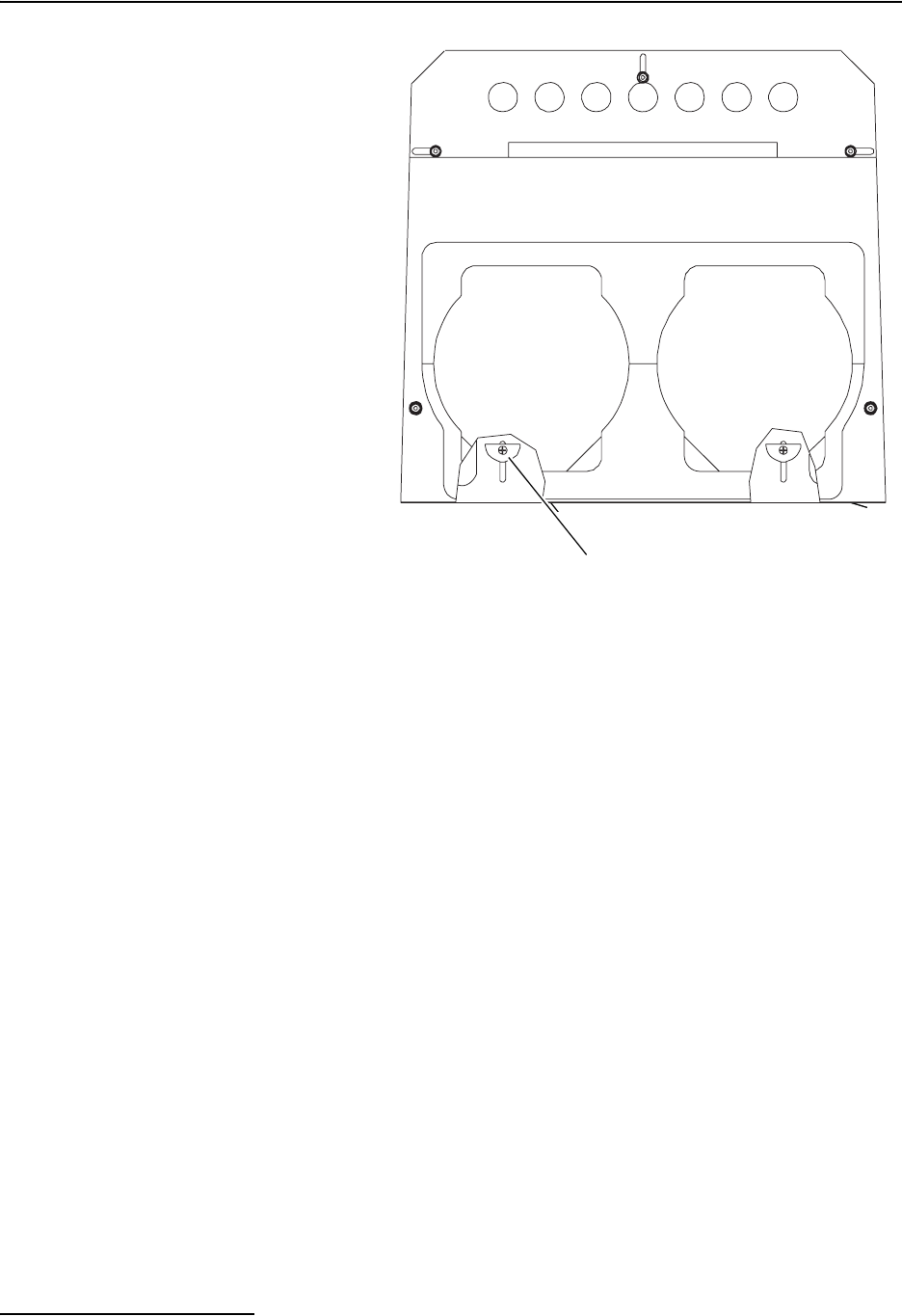
6712FR Refrigerated Sampler
Section 2 Installation/Preparation
2-6
Figure 2-4 Installing the 2-bottle Kit
2.2.2 Removing Racks Before removing the rack, place the lids on the bottles so the
samples do not spill. Remove the bottle rack by lifting the front
edge of the rack slightly to disengage it from the two ramps.
Then, pull it straight out of the refrigerator. Be careful not to
catch the distributor arm against the bottles.
2.2.3 Installing Composite
Bottles
Remove the distributor arm and discharge tube. Remove the dis-
tributor arm stop. If using the two bottle locating base, remove it.
Slide the composite bottle discharge tube on the bulkhead fitting.
Composite bottle kits have two lids, one with a hole drilled in the
center. Screw the lid with the hole in it on the bottle, and place
the bottle in the center of the mounting plate.
Thread the discharge tube through the hole in the lid. Always
use the lid to retain the discharge tube. It prevents the sampler
from spraying liquid inside the sample compartment instead of
the bottle.
2.3 Suction Line The suction line is the tubing from the sampling point to the
pump intake. The 6712FR uses a 3/8-inch ID suction line of
lengths 3 to 99 feet. Teledyne Isco offers vinyl or PTFE suction
lines. The PTFE tubing has a polyethylene jacket to protect it
from kinks and abrasions.
Secure the base
with these stops.
Install the distributor-shaft extension.
Use the 51
/4-inch extension for the 2-bottle
kit. The instructions on page 2-1 show you
how to remove the controller and replace
the extensions for each bottle kit.
Next, replace the controller, and adjust the
distributor arm to position A. Install the
arm and stop. See Installing the Distribu-
tor Arm and Discharge Tube on page 2-2.
Install over the mounting plate at the bot-
tom of the refrigerator, the locating base
which holds the 21
/2-gallon glass or 2 gal-
lon polyethylene bottles.
Begin by loosening the ramps. Move them
toward the front of the compartment so
that they will fit under the ridge of the lo-
cating base. (You can also remove them
completely.)
Remove the two front stops, and align the
holes on the sides of the locating base
with the holes for the stops in the mount-
ing plate. Secure the base by replacing
the stops.
Install the bottles, and position the arm
over each bottle.
NEVER MANUALLY ROTATE
THE DISTRIBUTOR ARM.
Ramps located under locating base.
Pull them to the front or remove them.
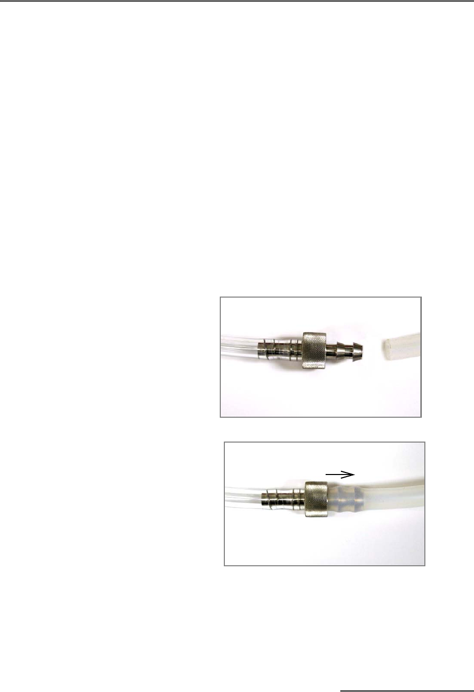
6712FR Refrigerated Sampler
Section 2 Installation/Preparation
2-7
The vinyl line contains a very low parts-per-million level of
phenols. If phenol content affects your sample analysis, use the
PTFE suction line.
When installing the sampler, be sure the vertical distance
between the liquid level and the pump is as small as possible.
2.3.1 Guidelines for
Measuring and Cutting
the Suction Line
• Cut the line to the desired length but use the shortest
length feasible for the installation.
• Cut the line in 1 foot increments. For instance, 4 feet,
not 31/2. If using metric units of measure, cut the line in
increments of 0.1 meter. Do not include the length of the
strainer in the measurement.
2.3.2 Attaching Suction Line
to Pump Tube
Attach the vinyl suction line to the pump tube with the 3/8-inch
tubing coupler. First, screw the threaded end into the suction line
until the flat surface is flush against the suction line
(Figure 2-5). Then, push the other end of the coupler into the end
of the pump tube until the other flat surface is flush against the
tubing.
Figure 2-5 Attaching the suction line to the pump tubing
Once the coupler is attached to the pump tube, removal is dif-
ficult, and may require cutting the tube.
1.
2.
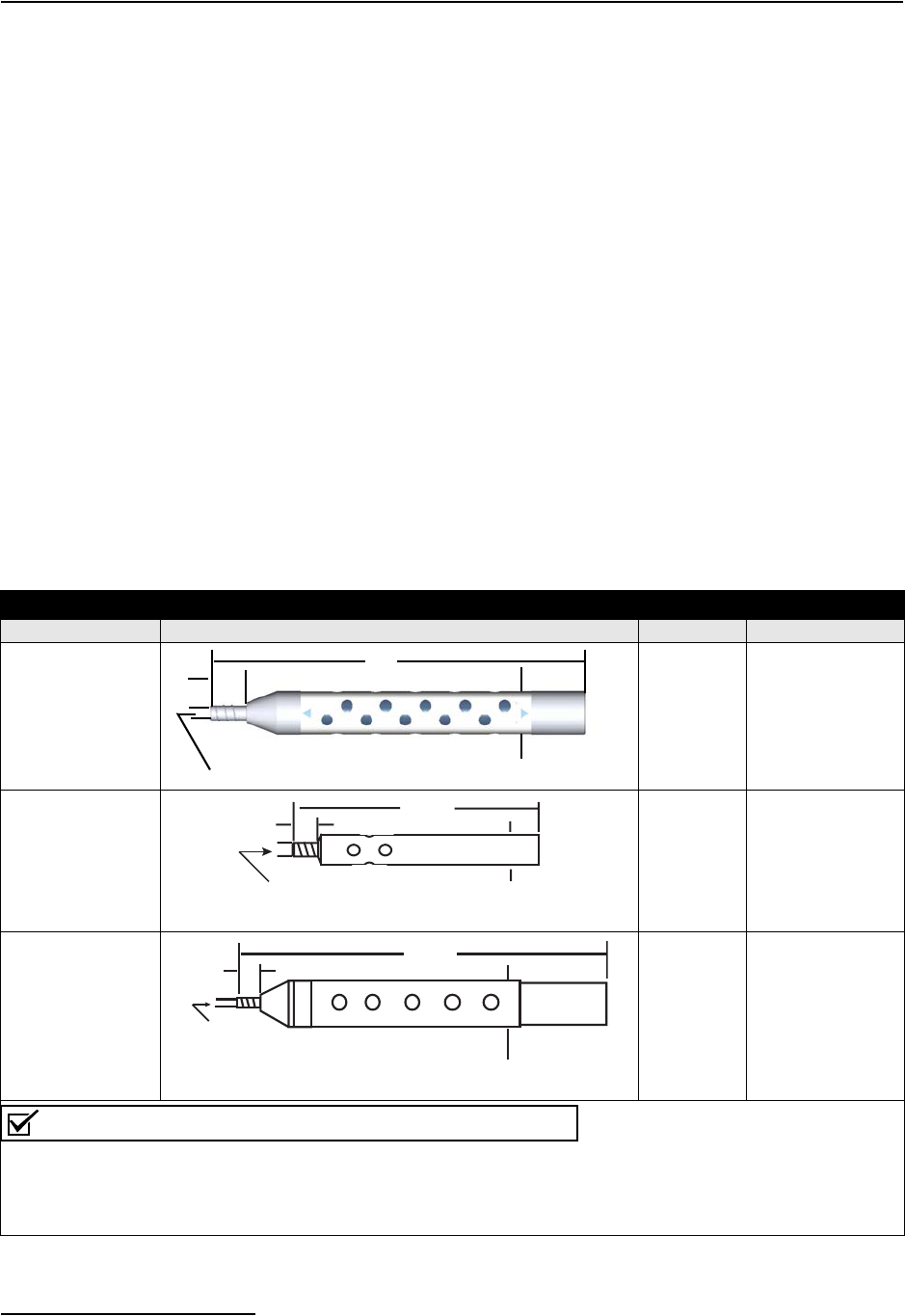
6712FR Refrigerated Sampler
Section 2 Installation/Preparation
2-8
2.4 Strainers Teledyne Isco offers three styles of strainer that help prevent
solids from clogging the suction line:
•3/8-inch standard weighted polypropylene strainer for
routine and priority pollutant sampling
•3/8-inch stainless steel low flow strainer
• Weighted CPVC-coated strainer for acidic liquid sources
To select the right strainer for your application, see Table 2-2.
To install the optional low flow strainer in PTFE suction line,
heat the end of the suction line to make it more pliable, then
carefully screw the strainer’s threaded connector into the suction
line.
2.4.1 Alternative to Strainers When sampling from high velocity streams with heavy sus-
pended solids, some field investigations suggest that more repre-
sentative samples are obtained without the strainer. Consider
attaching a short piece of thin walled aluminum tubing to the
end of the suction line; anchor the tubing so that the inlet opens
upstream. The aluminum tubing’s thin wall will not disturb the
flow stream, and most sample analyses disregard aluminum
ions. Under most conditions, the pre-sample purge removes any
debris over the tubing entrance.
Table 2-2 Selecting the Right Strainer
Strainer Dimensions Application Maximum Depth
3/8 Stainless
Steel Ends,
Polypropylene
Center
Routine
applica-
tions.
Vinyl Line:
22 feet (6.7m).
PTFE Line:
15 feet (4.5m).
3/8
Stainless Steel
Low Flow
Low flow
applica-
tions
Vinyl Line:
22 feet (6.7m).
PTFE Line:
15 feet (4.5m).
3/8
CPVC
Highly
acidic
liquids.
Vinyl Line:
4 feet (1.2m).
Note
• The suction lines will float when filled with air during the purge cycles and when depths exceed the
listed ratings. Secure the suction lines when sampling at depths exceeding the maximum ratings.
• All strainer dimensions are in inches.
• PTFE suction line is compatible only with the 3/8 stainless steel strainer.
1-1/4
.400
Diameter Diameter
1
10.5
.400
diameter
7
1
.562
diameter
.400
diameter
1
11.5
1- 5/16
Diameter
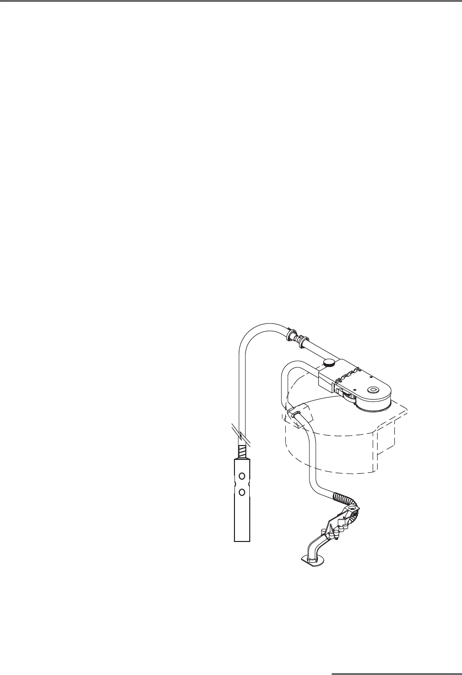
6712FR Refrigerated Sampler
Section 2 Installation/Preparation
2-9
2.5 How Does the Sampler
Work?
When the sampler takes a sample, it draws liquid through the
strainer and suction line to the pump tube. The liquid flows
through the pump tube and past the liquid detector, which senses
the liquid. From the detector, the liquid follows the pump tube
through the pump to the bulkhead fitting and then through the
discharge tube to the sample bottle.
A typical sampling cycle consists of:
1. The sampler moves the distributor arm over the bottle that
is to receive the sample.
2. The pump reverses for the pre-sample purge.
3. The pump direction changes, filling the suction line.
4. When the detector senses liquid, the sampler begins mea-
suring the sample.
5. After depositing the sample, the pump again reverses for
the post-sample purge.
Sampling cycles vary somewhat according to program settings
for distribution. The sampler can move the distributor arm
clockwise and counterclockwise, making a number of distribution
methods possible. (In this manual, the words “sample event”
refer to a full sampling cycle for any distribution.)
Figure 2-6 Identifying the Sampler Components
Other variations include extended-program settings for
suction-line rinses and sampling retries. A sampler running a
program with line rinses completes the pre-sample purge and
a
i
b
d
j
h
efg
c
a. Controller.
b. Peristaltic pump.
c. Liquid Detector.
d. Strainer
e. Suction line
f. Stainless Steel Coupling
g. A pump tube routed from the liq-
uid detector’s intake port
through the pump, out the detec-
tor’s discharge port, and over the
side of the controller to a bulk-
head fitting.
h. Bulkhead fitting.
i. Discharge tube running from the
bulkhead through the spring and
distributor arm.
j. Distributor arm and spring.
6712FR Refrigerated Sampler
Section 2 Installation/Preparation
2-10
then rinses the line. The suction line is purged after each rinse.
When programmed for sampling retries, the sampler will
attempt to pump a sample again if it fails on previous attempts.
2.5.1 Measuring Sample
Volume
“Sample volume” refers to the amount of liquid delivered into a
bottle. The volume is determined by the programmed value. The
volume is dependent on the volume per revolution of the pump,
which is dependent on the suction head. The 6712FR delivers the
sample by counting the pump revolutions and automatically
compensating for the suction head.
2.6 Installing the Sampler The following segment briefly describes initial sampler instal-
lation.
CAUTION
Tests indicate that the pump produces sound levels in excess
of 85db at one meter. Prolonged exposure to this sound could
result in hearing loss and requires the use of protective ear
plugs.
CAUTION
When using the 6712FR sampler with a 750 or 710 module,
transmitters such as cell phones or walkie talkies must not be
operated within 3 meters of the sampler. If water level readings
are fluctuating due to TV/radio station transmitter towers in the
area, the sampler must be relocated.
WARNING
The 6712FR samplers have not been approved for use in
hazardous locations as defined by the National Electrical
Code.
WARNING
If you must enter a manhole or other dangerous location to
install the sampler, observe standard safety precautions.
Refer to Appendix C for a discussion of safety
considerations.
2.6.1 Tips for Routing
Suction Line
Route the line so that it runs continuously downhill from the
sampler to the liquid source. This helps drain the line during
pre-sample and post-sample purges. When the sampler is used in
below freezing temperatures, there is a risk of the suction line
being frozen. A suitably warm sampling source can usually
prevent this, provided there are no loops in the suction line.
Some situations may require more protective measures, such as
insulation of the suction line, or heat tape. Thoroughly draining
the suction line minimizes the possibility of frozen liquid
clogging the line.
6712FR Refrigerated Sampler
Section 2 Installation/Preparation
2-11
2.6.2 Intake Placement For representative samples, place the intake in the main current
of the flow stream, not in an eddy or at the edge of flow. Placing
an intake at the bottom may produce samples with excess heavy
solids and no floating materials, while placement at the top may
produce the opposite conditions.
2.6.3 Positioning a Sampler Place the refrigerator on a relatively flat, horizontal surface.
Placing the refrigerator on a steep incline may cause the sample
to miss the bottle mouth.
When installing the sampler, be sure the vertical distance
between the level of the liquid and the pump is as small as pos-
sible.
CAUTION
The refrigerator’s lower compartment is not watertight. Do not
install in a location where the refrigerator’s lower compartment
could become submerged.
2.7 Connecting External
Instruments
The 6712FR sampler can be used in conjunction with several
types of external instruments.
2.7.1 Flow Meter To connect the sampler to an Isco open-channel flow meter, 4100
series flow logger, 2100 series flow module, or 1640 Liquid Level
Actuator, attach the sampler-to-flow meter cable to the Flow
Meter Connector. To connect the sampler to a closed-pipe flow
meter, attach an Isco 4-20 mA Input Interface device to the
sampler’s Flow Meter connector. Plug the line cord into an AC
power outlet. Be sure it is connected to 120 volts AC (optional
230 volts AC). When using the sampler with an external
instrument, remember these guidelines:
• Both the sampler and the flow instrument must be on
and running a program.
• If using a flow meter, logger, or module for flow pacing,
the sampler and the flow instrument must both run
programs with flow pacing settings.
• If using a flow meter or flow logger for trigger pacing,
the sampler must run a program with flow pacing
settings, and the flow instrument must run a program
with trigger pacing settings.
• When the sampler runs an event-paced program, it
disregards pacing pulses from a flow meter or flow
logger. However, the sampler continues to monitor for
enable signals.
2.7.2 Rain Gauge Connector Connect the rain gauge, SDI-12 Sonde, or Refrigerator Temper-
ature Sensor connect cables to the nine-pin Rain Gauge Con-
nector. When connecting a rain gauge and an SDI-12 Sonde, or
rain gauge and a Refrigerator Temperature Sensor, use the
appropriate Y-connect cable. See the Accessories appendix at the
end of this manual.
Flow Meter
Connector
Icon
6712FR Refrigerated Sampler
Section 2 Installation/Preparation
2-12
WARNING
Most Isco flow meters are not certified for use in hazardous
locations as defined by the National Electrical Code.
Contact your Teledyne Isco representative for your
equipment’s status. Never operate equipment in hazardous
locations that has not been certified as safe for such use.
Refer to Appendix C in the back of this manual for more
safety information.
Note
Select Extended Programming to use the SDI-12 sonde. (See
Switching Between Standard and Extended Modes on page
4-1.)
Note
Update the Hardware Setup whenever you add or remove an
SDI-12 sonde. (See Section 6.) In extended programming, rain
gauge and SDI-12 sonde readings are only available if they are
selected in the Hardware Setup.
Rain Gauge
Connector Icon
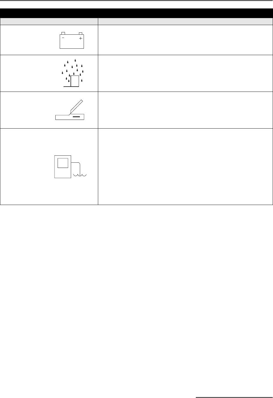
6712FR Refrigerated Sampler
Section 2 Installation/Preparation
2-13
Table 2-3 Connecting Isco Instruments to the Sampler
Connector Icon Connect These Instruments:
Power Source
12 volt power source
Rain Gauge
674 Rain Gauge
Programmable I/O Pins (pins C, H, and I)
SDI-12 Sonde
Refrigerator Temperature Sensor
Interrogator
581 RTD (Rapid Transfer Device)
IBM PC or compatible computer running FLOWLINK or SAMPLINK
External Modem
External Data Logger/Controller
Flow Meter
1640 Liquid Level Actuator
2100 Series Flow Modules
3000 Series Flow Transmitters
4100 Series Flow Loggers
4200 Series Flow Meters
Master/Slave Sampler
Pulse Duration Input Interface
4-20 mA Input Interface
Closed-Pipe Flow Meter (with 4-20 mA Input Interface)

6712FR Refrigerated Sampler
Section 2 Installation/Preparation
2-14
2.8 Locking the Sampler The refrigerator is equipped with a lockable latch for the top
cover and a lockable catch for the door handle. To lock the refrig-
erator, use two padlocks, one for the top cover and one for the
door.
2.9 Servicing the Sampler Servicing the sampler includes:
• Collecting the filled sample bottles and replacing them
with clean bottles;
• Collecting the data recorded by the sampler during the
program.
Samplers are usually serviced after they complete a sampling
program. When working up a service schedule, you will need to
estimate the program completion time. You should also be
familiar with the program’s settings for the start time or if the
sampler is programmed for continuous sampling.
Continuous sampling is controlled by the distribution setting
entered at the “RUN CONTINUOUSLY?” screen. A “YES”
response directs the sampler to reset the distribution sequence
and continue the countdown to the next sample event. Appro-
priate service intervals will prevent overfilled bottles.
3-1
6712FR Refrigerated Sampler
Section 3 Programming Introduction
Before programming the 6712FR, you should become familiar
with its keys and how to use the screens.
The 6712FR Sampler has two sets of programming modes. The
first mode, Standard Programming, lets you set up typical
sampling programs easily and efficiently. The second mode,
Extended Programming, lets you create sophisticated pro-
grams for complex sampling applications.
All of the sampling features available in standard programming
mode are available in extended programming mode. However,
extended programming provides many additional features.
Standard and extended programming features are explained in
separate sections. This section focuses on some basic features
that are common to both programming modes, such as using the
menus and setting the clock.
CAUTION
This sampler has a high performance pump. As with all such
pumps, it relies upon liquid to cool working components. If the
sampler is programmed to pump in the absence of liquid in
excess of 5 minutes, excessive heat buildup may damage the
paddles, rollers, and housing. Ensure that the liquid inlet is
completely immersed.
3.1 Initial Operation
Turn the sampler on by pressing the Standby key. It is labeled
with this icon: . The start-up screen appears first.
It remains on the display for about eight seconds or until you
press a key. It tells you the type of programming screens the
sampler is currently using — standard or extended — and gives
you a tip about the on-line help. The main menu screen, shown
below, appears next.
6712 SAMPLER
STANDARD PROGRAMMING
For HELP at any
screen press ? key.
RUN
PROGRAM
VIEW REPORT
OTHER FUNCTIONS
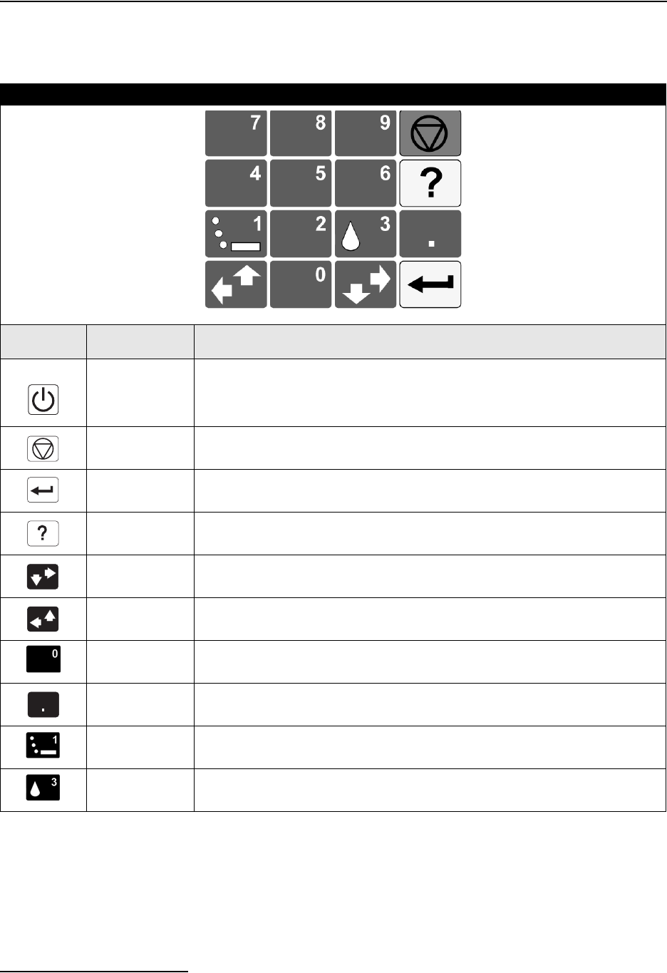
6712FR Refrigerated Sampler
Section 3 Programming Introduction
3-2
(If a module is attached, a different screen may appear first. See
the module manual for more information.)
Table 3-1 About the Keypad
Key Name Function
Standby Turns sampler on or off.
Stop Stops the pump or distributor. Pauses a running sampling program.
In programming screens, returns to a previous screen.
Enter Accepts a menu choice or number entry and goes to next screen.
Help In programming screens, displays a brief help message.
Down-Right
Arrow Selects the menu option right or below the current choice.
Up-Left Arrow Selects the menu option left or above the current choice.
Numbers Types a number.
Decimal Point Types a decimal point.
Pump Reverse Press when at the main menu to run the pump in reverse.
Pump
Forward Press when at the main menu to run the pump forward.

6712FR Refrigerated Sampler
Section 3 Programming Introduction
3-3
The sampler is programmed at the factory so that the standard
programming screens appear when you first turn the sampler on.
You can switch between programming modes by typing in a
numerical command at the main menu:
• At the main menu type 6712.2 to show the extended
programming screens.
• At the main menu type 6712.1 to show the standard
programming screens.
The sampler will continue to use the program mode you selected,
even if the sampler is turned off and on again, until you man-
ually switch to the other programming mode.
With the display backlight activated, the screen will glow for
several seconds following your last keystroke.
If you press a key and the screen text does not change, it is
probably because the keystroke turned the backlight on, instead
of performing its function. Press the same key again.
3.1.1 Selecting a Language You have the option of having screens display in English or
another language. The default is English. At the main menu,
type 6712.8:
Use the arrow keys to move between the choices (languages other than
those shown above could appear on your unit). When the language
choice you want is blinking, press ↵(Enter). The ↵ (Enter) key
always accepts the blinking option.
3.2 Using Menus and
Entering Numbers
A menu is a list of options. The main menu has four options:
•RUN
• PROGRAM
•VIEW REPORT
• OTHER FUNCTIONS
The options identify the operations that can be performed from
the menu. For example, to run the sampling program, select
RUN; to modify the program, select PROGRAM.
3.2.1 Selecting Menu
Options
In menu screens, one menu option always blinks.
•Press ↵ when the blinking option is the one you want; it
will accept your choice and go to the next screen.
• Select a different option by pressing an arrow key until
the option you want blinks. Then press ↵.
3.2.2 Entering Numbers Number-entry screens prompt you to enter a value. An example
is shown to the left.
ENGLISH
SPANISH
The Main Menu
RUN
PROGRAM
VIEW REPORT
OTHER FUNCTIONS
6712FR Refrigerated Sampler
Section 3 Programming Introduction
3-4
To enter a number:
Press the number keys to type the number. Then, press ↵. As
soon as you press ↵, the sampler saves your number and moves
to the next screen. In some screens, you can use the . (Decimal
Point) key in a number.
Some screens display the range of acceptable numbers between
parentheses. If an entry is too low or high, the controller beeps
and erases the entry. Type a new number and continue.
3.3 Quick View Screens Quick View screens are a special type of menu screen. They show
the current program settings and let you move quickly through
the program. You must change the programming style to QUICK
VIEW/CHANGE to see the quick view screens, as shown below:
3.3.1 Paging Through Quick
View Screens
The arrows in the corners of each quick view screen are menu
options that let you move from one quick view screen to another.
Select the up arrow ( ↑ ) to go to the previous screen.
Select the down arrow ( ↓ ) to go to the next screen.
Press Stop to return to the main menu.
Because the forward arrow is always blinking when the screen
appears, you can simply press ↵ to go to the next quick view
screen, making it easy to page through the screens.
3.3.2 Changing Settings in a
Quick View Screen
Although the quick view screens offer you a quick way to see the
program settings, they also provide you with a way to change set-
tings. Using quick view screens to change settings is sometimes a
faster way to change a program because you can go quickly to the
setting or settings that needs updating.
To change the program settings in a quick view screen:
Press an arrow until the setting blinks. Press ↵. The 6712 then
displays the screen used to change the setting.
SUCTION LINE LENGTH
IS __ ft
(3-99)
•Type the length of the
suction line. Acceptable
values are shown between
the parentheses. Press ↵ to
accept the number.
1
RUN
PROGRAM
VIEW REPORT
OTHER FUNCTIONS
Select OTHER FUNCTIONS.
2
MAINTENANCE
MANUAL FUNCTIONS
PROGRAMMING STYLE
Select PROGRAMMING STYLE.
3
PROGRAMMING STYLE
NORMAL
QUICK VIEW/CHANGE
Select QUICK VIEW/CHANGE.

6712FR Refrigerated Sampler
Section 3 Programming Introduction
3-5
The following Quick View screens show you how to change the
sample volume. Begin by paging through the quick view screens
until you see the screen containing the sample volume setting:
When you change a setting, the sampler stores the new settings
and returns to the updated quick view screen. You can repeat
this process until all settings shown in the quick view screens
have been changed. When you are done, select the screen’s
forward arrow to move to the next quick view screen, or press
Stop to return to the main menu.
3.4 Clock and Calendar You may have to set the internal clock or calendar. The samplers
are shipped with their clocks set to U.S. Central Standard time.
If your sampler operates in a different time zone, you will have to
reset the clock. The example below shows you how to find the
time and date screen.
RUN
PROGRAM
VIEW REPORT
OTHER FUNCTIONS
•To see the Quick View
screens, select PROGRAM.
↑
SITE DESCRIPTION:
“SITE 29 “ ↓
•Use the keypad’s arrow key
to select ↓ for the next quick
view screen. When ↓ is
blinking, press ↵.
•Use the keypad’s arrow key
to select ↑ for the previous
quick view screen. When ↑
is blinking, press ↵.
•Use the keypad’s arrow key
to select the program
setting. When the setting is
blinking, press ↵ to display
the screen used to change
the setting.
•Press Stop for the main
menu.
•All quick view screens work
the same way.
↑ 200 ml SAMPLES ↓
•Press the arrow key until
200 ml SAMPLES blinks. Then
press ↵.
SAMPLE VOLUME:
250 ml (10-1000)
•Type the new sample volume
and press ↵.
↑
250 ml SAMPLES ↓
6712FR Refrigerated Sampler
Section 3 Programming Introduction
3-6
When setting the clock and calendar, use a 24-hour clock for
times and the day-month-year format for dates. The illustration
at the left shows blanks for each position that accepts an entry.
The positions are called fields. When this screen appears on your
sampler, the fields will contain the sampler’s current settings for
the time and date.
• To move from one field to another without changing the
setting, press the arrow keys. Use this technique when
you want to change only one or two settings.
• Change the setting by typing a new number. Press ↵ to
accept the new setting.
For example, to enter 2:00 p.m. (2:00 p.m is 14:00 on a 24-hour
clock), type 14. Press ↵. Next, type 0 (zero) for the minutes, and
press ↵. To enter a date, such as January 22, 2001, type: 22 ↵
01 ↵ 01 ↵ .
3.4.1 Setting the Clock and
Calendar
3.4.2 Menu Screens: Clock
Start Times
There are four start time settings you can use in a sampling
program. This section discusses only one of these settings, the
clock start time. A clock start time lets you set up a sampling
program that starts at the same time on one or more days of the
week. For example, you may want to begin sampling at 6:00 a.m.
on Monday through Friday (refer to the screen below).
To select a day or days from the menu:
1. Press an arrow key until the cursor is on the correct day.
Then, press ↵.
2. Repeat these steps until each day you want is blinking.
3. Press an arrow until DONE blinks. Press ↵.
Entering Times and Dates
ENTER TIME AND DATE:
HH:MM DD-MON-YY
__:__ __-__-__
•Move from one field to
another by pressing the
arrow keys.
•Change a setting in a field
by typing a number. Press ↵
to accept the new setting.
1
RUN
PROGRAM
VIEW REPORT
OTHER FUNCTIONS
Select OTHER FUNCTIONS.
2
MAINTENANCE
MANUAL FUNCTIONS
PROGRAMMING STYLE
Select MAINTENANCE.
3
SET CLOCK
PUMP TUBE ALARM
INTERNAL BATTERY
DIAGNOSTICS
Select SET CLOCK.
4
ENTER TIME AND DATE:
HH:MM DD-MON-YY
14:00 22-JAN-01
Enter the time and date.
5
SET CLOCK
PUMP TUBE ALARM
INTERNAL BATTERY
DIAGNOSTICS
Press Stop to return to the main
menu.

6712FR Refrigerated Sampler
Section 3 Programming Introduction
3-7
To remove days from the list:
1. Press an arrow key until the cursor is on the day you want
to remove. Press ↵ to deselect it.
2. When finished, select DONE and press ↵
3.5 Menu Screens: Site
Descriptions and
Program Names
The sampler has two text-entry menus, one for site description
and another for an extended-program name. They work in the
same way. A site description is commonly a number, address, or
other short note that helps identify the monitoring site.
Extended programming has a similar screen that lets you enter
program names for stored programs.
The example on the next page shows how to change the site
description from FACTORY01 to SITE 29. Line 1 contains text
between two quotation marks. Lines 2 and 3 contain the menu
options — numbers, letters, and punctuation marks — used to
spell out the description. In line 3, the space between the
ampersand (&) and the double quotes (") is a space character.
Line 4 contains two additional options:
• BACK-UP, an option that moves the cursor on the text
line to the left one character.
• DONE, an option that tells the sampler to save the text.
NO DELAY TO START
DELAYED START
CLOCK TIME
WAIT FOR PHONE CALL
•Select CLOCK TIME.
FIRST SAMPLE AT:
06:00
•Type the time of day and
press ↵.
SELECT DAYS:
SU MO TU WE TH FR SA
DONE
•Press an arrow key until the
cursor is on the correct day.
Then, press ↵. To remove a
day, move the cursor to it
and press ↵ to deselect it.
•Repeat these steps
until each day you want
is blinking.
•Press an arrow until DONE
blinks. Press ↵.
Using the Clock
Start Time Menu
6712FR Refrigerated Sampler
Section 3 Programming Introduction
3-8
The cursor is the blinking rectangle that identifies the current
field. When the screen first appears, the cursor blinks on the first
character of the text in line 1. The matching character in line 2 or
3 also blinks.
When you press ↵, the cursor on line 1 moves to the right one
position, and, at the same time, the sampler blinks on the
matching character on lines 2 or 3.
To change any character in the text line:
1. Press the left or right arrow until the replacement charac-
ter on lines 2 or 3 blinks.
2. Press ↵. The replacement character will appear on the first
line, and the cursor will move to the next character.
Repeat steps 1 and 2 until the text in the top line is complete.
3. Finish the entry by selecting DONE. Then, press ↵.
Some additional tips for using the text-entry menus:
• Hold an arrow key down for faster movement.
• If your description uses all ten spaces in the text line,
the sampler automatically moves to the next screen as
soon as you add the tenth character.
• You can enter numbers by pressing the number keys.
• Erase characters by replacing them with a space
character.
• Select the BACK-UP option to move the cursor to the
left.
• To leave the menu before completing the entry, press
Stop. The sampler will display this menu:
Select YES to save any changes made. Select NO to
leave the original description (or program name)
unchanged.
3.6 Messages The sampler has four sets of messages that supplement the pro-
gramming screens. Information messages tell you about pro-
gramming status. Help Notes are brief comments associated
with programming screens describing the setting or offering
assistance. Warning messages tell you something is different
from Isco’s standard. Operation messages report the sampler’s
status as it runs a program.
SITE: “SITE 29_”
ABCDEFGHIJKLMNOPQRST
UVWXYZ-&_"0123456789
BACK-UP DONE
•Press 29 on the keypad, then
Up-Left until space blinks.
Press ↵.
SITE: “SITE 29 ”
ABCDEFGHIJKLMNOPQRST
UVWXYZ-&_"0123456789
BACK-UP DONE
•Press the Down-Right arrow
until DONE blinks. Press ↵.
Changing the Site Name
SITE: “FACTORY01”
ABCDEFGHIJKLMNOPQRST
UVWXYZ-& “0123456789
BACK-UP DONE
SITE: “SACTORY01”
ABCDEFGHIJKLMNOPQRST
UVWXYZ-& “0123456789
BACK-UP DONE
•Press the Down-Right arrow
until the S on line 2 blinks.
Then, press ↵.
SITE: “SICTORY051”
ABCDEFGHIJKLMNOPQRST
UVWXYZ-& “0123456789
BACK-UP DONE
•Press the Up-Left arrow
until the I blinks. Press ↵.
•Continue pressing arrow
keys to select T, E, and
space. Press ↵ after
selecting each character.
SAVE CHANGES?
YES NO
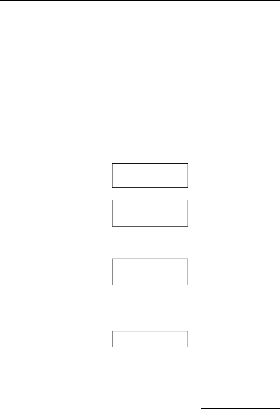
6712FR Refrigerated Sampler
Section 3 Programming Introduction
3-9
3.6.1 Information Messages These are brief messages about the programming status, such as
“‘ROM’ PASSED TEST” or the status message that displays
when you first start up the sampler. Information messages are
displayed for four seconds, unless they are terminated by
pressing any key on the keypad.
3.6.2 Help Notes To see a Help note:
1. Press the ? (Help) key.
2. When the note requires several screens, the word “more”
appears in the lower-right corner. Press ↵ for the next note.
3. Move back and forth between screens by pressing the
arrow keys.
4. Press Stop at any time to return to the programming
screen.
Most help notes refer to a related section in this manual. Screens
that require extensive explanation have notes that contain only a
reference to the manual. Sections mentioned in the notes appear
in the index and the table of contents.
SUCTION LINE LENGTH
IS 7 ft
(3-99)
•Press ? (Help).
Enter the length of
suction line only,
excluding strainer
and pump tube. <more>
•Press ↵ or Down-Right to
see the next screen.
•Press Stop to return to the
programming screen.
See “Installing
Suction Line” in
your manual.
<more>
•Press ↵ or Down-Right to
see the next screen.
•Press Up-Left to see the
previous screen.
•Press Stop to return to the
programming screen.
Press the red STOP
key to exit HELP.
•Press Up-Right to see the
previous notes.
•Press Stop to return to the
programming screen.
Using Help Notes
Although this example shows
the Help Notes that are asso-
ciated with the suction line
length screen, you can use the
same technique to see help
notes for other screens.

6712FR Refrigerated Sampler
Section 3 Programming Introduction
3-10
3.6.3 Warning Messages Warning messages appear when the sampler determines some-
thing is out of the ordinary. For example, the following warning
appears when you type a number that is larger than the
standard bottle volume:
The 6712 does accept nonstandard volumes because you might
use a nonstandard container occasionally. For a list of recom-
mended volumes for Isco bottles press the ? (Help) key at the
“Bottle Volume Is” screen, or refer to the Technical Specifications.
The 6712 uses the bottle and sample-volume settings to
determine the maximum number of samples that can be
deposited without overfilling the bottles. Entering a volume that
exceeds the standard volume may cause the sampler to overfill
the bottle.
3.6.4 Operation Messages An operation message reports the sampler’s status as it runs a
program. An example is shown below.
3.7 Menu Trees Selecting a menu option will take you to a number-entry screen
or another menu screen. The screens are organized in a
branching structure that resembles a tree. Refer to Figure 3-1 for
a simple chart of the menu tree for standard programming. The
standard programming structure is different — much simpler —
than the extended programming structure. Charts that show you
most of the sampler’s screens appear in Appendix A, Flowcharts.
The entire structure changes a little when a module is attached
because the sampler adds a set of screens for a module as soon as
it detects the module’s presence. The manuals for each module
contain menu trees for its programming screens.
BOTTLE VOLUME IS
3500 ml (300-30000)
WARNING!
STANDARD BOTTLE
VOLUME EXCEEDED!
PROGRAM WILL START
AT 06:00 TU 20-FEB
05:56:22 TU 20-FEB
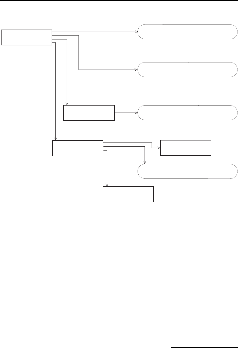
6712FR Refrigerated Sampler
Section 3 Programming Introduction
3-11
Figure 3-1 Menu Tree for Standard Programming
RUN
PROGRAM
VIEW REPORT
OTHER FUNCTIONS
SET CLOCK
SET PUMP TUBE ALARM
INTERNAL BATTERY
DIAGNOSTICS
VIEW DATA
PRINT DATA
SYSTEM IDs
CONFIGURE REPORTS
MAINTENANCE
MANUAL FUNCTIONS
PROGRAMMING STYLE
PROGRAMMING STYLE:
NORMAL
QUICK VIEW/CHANGE
See Running Programs on page 4-10
See the screen charts in Appendix A.
See Reports on page 4-18.
See Figure A-8, Manual Functions
Screens, on page A-8.

6712FR Refrigerated Sampler
Section 3 Programming Introduction
3-12

4-1
6712FR Refrigerated Sampler
Section 4 Standard Programming
The 6712FR Sampler has two sets of programming screens. The
first set, called standard programming screens, lets you set up
typical sampling programs easily and efficiently. The second set,
extended programming screens, lets you create sophisticated
programs for complex sampling applications.
All of the sampling features available within the standard pro-
gramming screens are available in extended programming.
However, extended programming provides several additional fea-
tures which are discussed in the next section. Menu flowcharts
for both sets of programming screens are in Appendix A.
4.1 Switching Between
Standard and
Extended Modes
Factory default settings cause the sampler to begin in standard
programming mode the first time you turn it on. The start-up
screen tells you which programming mode the sampler is cur-
rently using. You can switch between programming modes by
entering a numerical command at the main menu:
• At the main menu, type 6712.1 to enter standard
programming mode.
• At the main menu, type 6712.2 to enter extended
programming mode.
4.2 Language Selection,
Units of Length
You have the option of displaying screens in English or Spanish
(or possibly another language). The default is English. At the
main menu, type 6712.8 to display:
Use the arrow key to move between the two choices. When the
desired choice is blinking, press ↵.
If you select the English option, you will advance to a second
screen that asks you to select your units of length:
RUN
PROGRAM
VIEW REPORT
OTHER FUNCTIONS
Main Menu
ENGLISH
SPANISH
SELECT UNITS FOR
LENGTH:
ft m
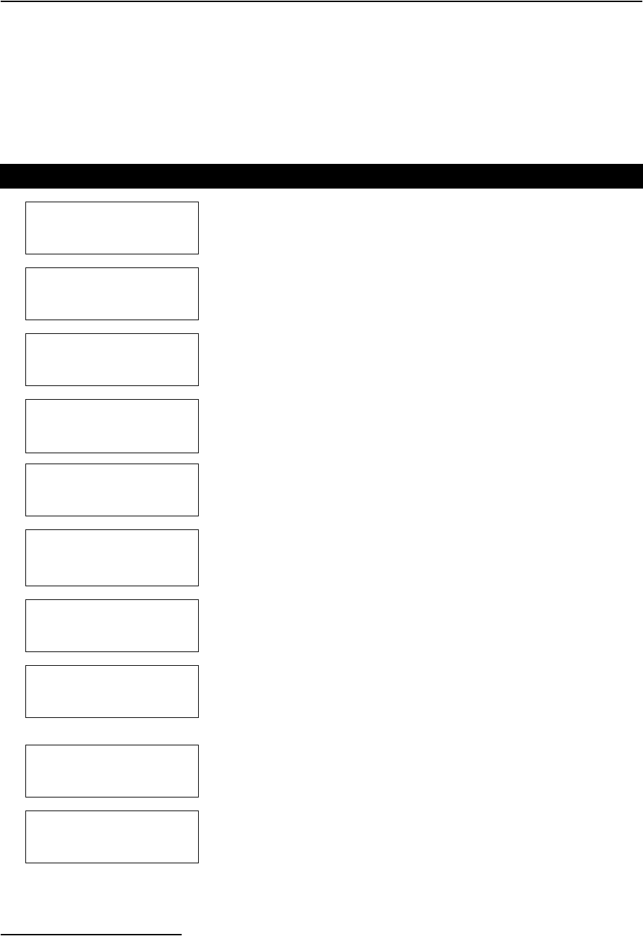
6712FR Refrigerated Sampler
Section 4 Standard Programming
4-2
Use the arrow key to move between the two choices, feet or
meters. When the desired choice is blinking, press ↵. The default
unit of length for the Spanish option is meters.
4.3 Programming
Examples
The following table is an example of time-paced sampling.
Further details about some of the menu items are provided in
later sections.
Table 4-1 Standard Program: Sample Every 15 Minutes, One Sample Per Bottle
1
6712 SAMPLER
STANDARD PROGRAMMING
For HELP at any
screen press ? key.
Turn the sampler on by pressing the On/Off key. Press ↵.
This screen disappears on its own after 8 seconds.
2
RUN
PROGRAM
VIEW REPORT
OTHER FUNCTIONS
The option PROGRAM will be blinking. Press ↵.
3
SITE DESCRIPTION:
“FACTORY051“
CHANGE?
YES NO
The option NO will be blinking. Press ↵.
For the purposes of this example, it isn’t necessary to change the description.
4NUMBER OF BOTTLES:
12481224
Select the number of bottles in your bottle kit by pressing either arrow key
until the correct number blinks. Press ↵. For this example, select 24.
5BOTTLE VOLUME IS
1000 ml (300-30000)
Type the volume for the bottles in your kit. For this example, 1000 is correct,
so simply press ↵.
6SUCTION LINE LENGTH
IS 10 ft
(3-99)
Type the length of the suction line, then press ↵.
If you change the length, the sampler will display a message,
“PLEASE WAIT!. . . GENERATING PUMP TABLES.”
7TIME PACED
FLOW PACED
Because this example requires samples every 15 minutes, select TIME
PACED by pressing an arrow until the option TIME PACED blinks. Then,
press ↵.
8
TIME BETWEEN
SAMPLE EVENTS
0 HOURS, 15 MINUTES
Type 0 for hours and press ↵. Type 15 for minutes and press ↵.
Tip: Move back and forth between hours and minutes by pressing an arrow
key.
9
SEQUENTIAL
BOTTLES/SAMPLE
SAMPLES/BOTTLE
Because this program requires one sample in each bottle, select
SEQUENTIAL by pressing an arrow until the option SEQUENTIAL blinks.
Then, press ↵.
10
RUN CONTINUOUSLY?
YES NO
For this example, select NO by pressing an arrow until the option blinks.
Then, press ↵. Selecting YES allows the program to run indefinitely by
repeating the sample distribution. Continuous sampling assumes that filled
bottles are replaced with empty bottles at regular service intervals.
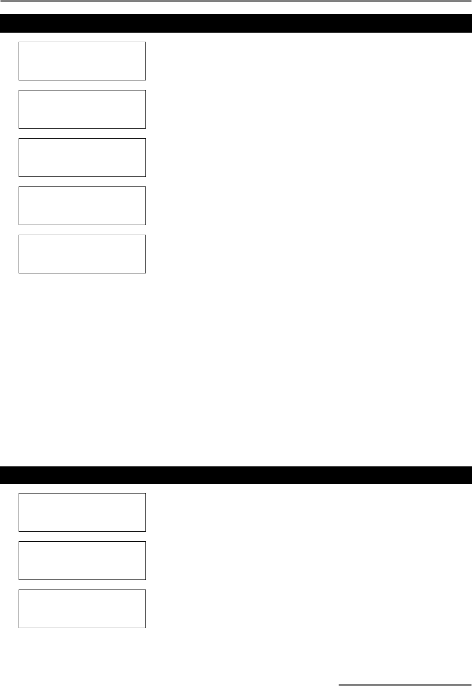
6712FR Refrigerated Sampler
Section 4 Standard Programming
4-3
The following table is an example of flow-paced sampling.
• Program type: Standard
• Site description: SITE 29
• Bottle kit: 24, 1000 milliliter bottles
• Suction line length: 7 feet
• Pacing: Flow pacing, every two pulses
• Distribution: 2 bottles per sample
• Sample Volume: 250 milliliters
• Start time: Clock Time, 6:00 a.m. on Monday,
Wednesday, Friday
• Module: No module installed
11 SAMPLE VOLUME:
200 ml (10-1000)
Type the volume of the sample you want deposited in each bottle. Then,
press ↵.
12
NO DELAY TO START
DELAYED START
CLOCK TIME
WAIT FOR PHONE CALL
For this example, select DELAYED START by pressing an arrow until the
option blinks. Then, press ↵.
13
FIRST SAMPLE
AFTER A
5 MINUTE DELAY
(1-999)
Type the delay period you want between the time you run the program and
the time the sampler takes the first sample. Then, press ↵.
14
PROGRAMMING COMPLETE
RUN THIS PROGRAM
NOW?
YES NO
Run the program immediately by selecting YES. Select NO if you want to
run the program later by selecting RUN from the main menu. Press ↵ after
making your choice. In this example, NO is selected.
15
RUN
PROGRAM
VIEW REPORT
OTHER FUNCTIONS
Run the program by selecting RUN and pressing ↵.
Table 4-1 Standard Program: Sample Every 15 Minutes, One Sample Per Bottle (Con-
Table 4-2 Standard Program: Flow-Paced Sampling, Two Bottles Per Sample
1
6712 SAMPLER
STANDARD PROGRAMMING
For HELP at any
screen press ? key.
2
RUN
PROGRAM
VIEW REPORT
OTHER FUNCTIONS
Select PROGRAM.
3
SITE DESCRIPTION:
“FACTORY051“
CHANGE?
YES NO
Select NO.
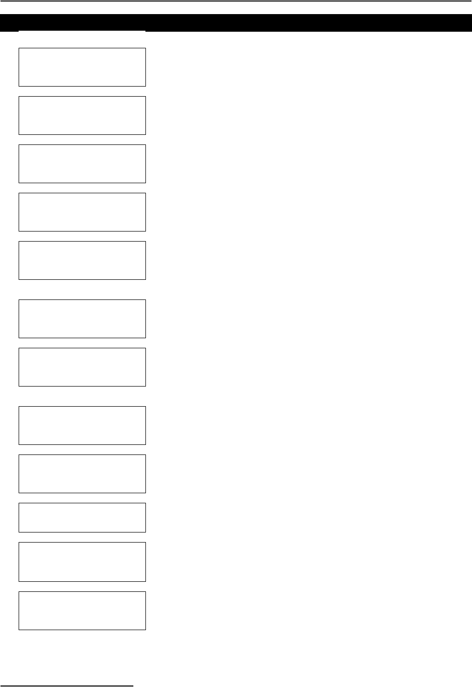
6712FR Refrigerated Sampler
Section 4 Standard Programming
4-4
4NUMBER OF BOTTLES:
12481224
Select 24.
5BOTTLE VOLUME IS
1000 ml (300-30000)
Enter 1000.
6SUCTION LINE LENGTH
IS 10 ft
(3-99)
Enter 7.
7TIME PACED
FLOW PACED
Select FLOW PACED.
8
FLOW BETWEEN
SAMPLE EVENTS:
2 PULSES (1-9999)
Enter the number of pulses between sample events.
9
SEQUENTIAL
BOTTLES/SAMPLE
SAMPLES/BOTTLE
Select BOTTLES/SAMPLE.
10
RUN CONTINUOUSLY?
YES NO
For this example, select NO by pressing an arrow until the option blinks.
Then, press ↵. Selecting YES allows the program to run indefinitely by
repeating the sample distribution. Continuous sampling assumes that filled
bottles are replaced with empty bottles at regular service intervals.
11 1 BOTTLES PER
SAMPLE EVENT (1-24)
Enter 2.
12
NO DELAY TO START
DELAYED START
CLOCK TIME
WAIT FOR PHONE CALL
Select CLOCK TIME.
13
START FLOW COUNT AT:
00:00 Enter 6, then enter 0.
This is the time at which the sampler will start the pacing countdown.
14
SELECT DAYS:
SU MO TU WE TH FR SA
DONE
Select MO, WE, and FR.
Use the arrow keys and ↵ to select the days. When the correct days are
blinking, select DONE and press ↵.
15
PROGRAMMING COMPLETE
RUN THIS PROGRAM
NOW?
YES NO
Select NO.
Table 4-2 Standard Program: Flow-Paced Sampling, Two Bottles Per Sample (Contin-
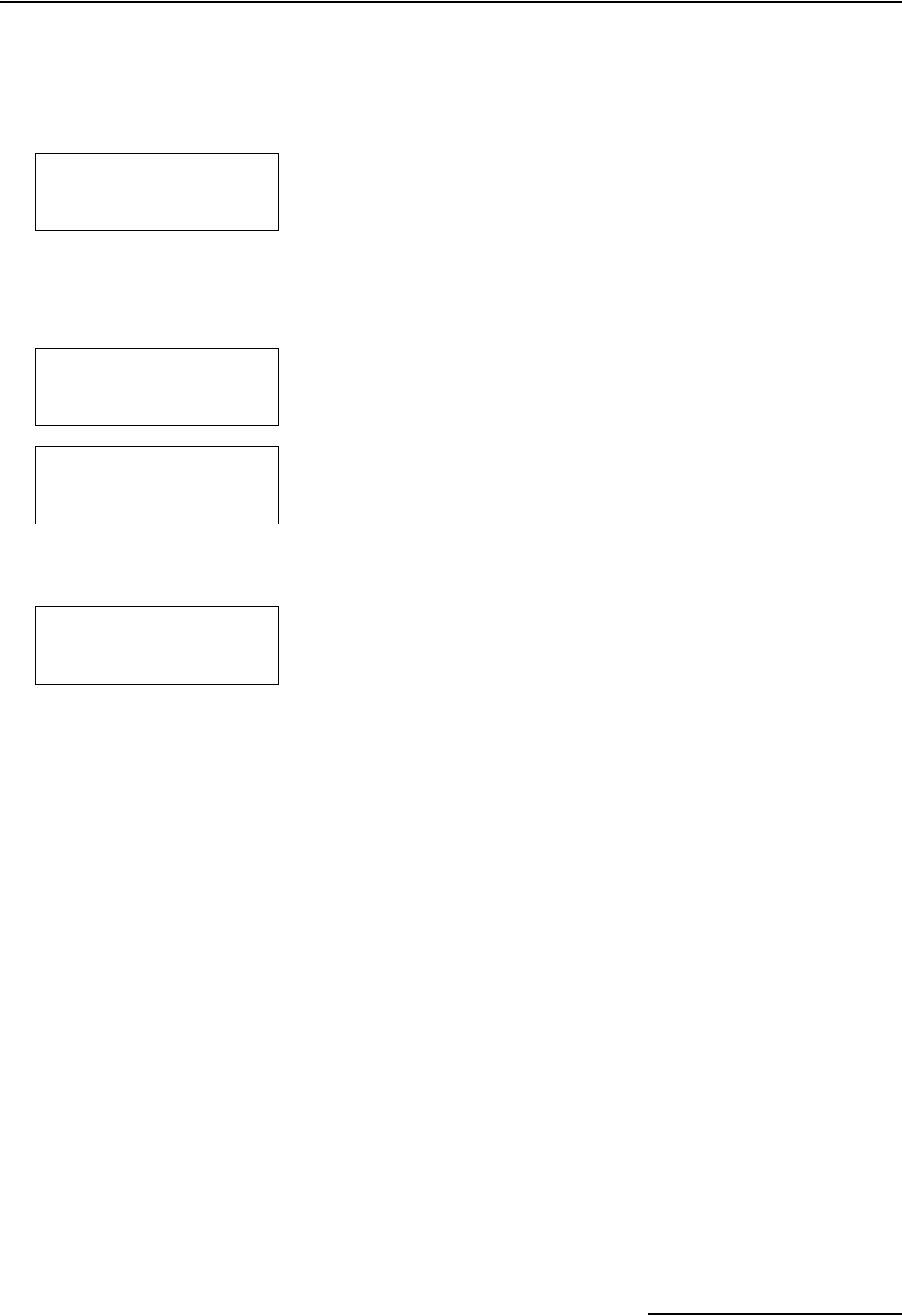
6712FR Refrigerated Sampler
Section 4 Standard Programming
4-5
4.4 Pacing
Sample pacing is the rate at which the sampler takes samples.
Depending on the type of pacing you select, the rate is controlled
by the sampler’s internal clock or by inputs received from con-
nected instruments.
Standard programming provides time pacing and flow pacing
(refer to Step 7 in the previous two programming examples). In
time-paced sampling, the interval between samples is a constant
time interval. When you program the sampler for time pacing,
the sampler prompts you to enter the time between sample
events in hours and minutes. Time paced programs always take
a sample at the start time.
Flow paced sampling requires a flow meter, flow logger, or a
module. A flow meter or flow logger paces a sampler by sending
an electronic signal to the sampler after measuring a specified
volume of liquid. Because each pulse represents a volume
interval, flow pacing rates are proportional to the volume of
water flowing through the channel.
When you program the sampler for flow pacing and are using a
flow meter or flow logger, the sampler prompts you to enter the
interval between sample events in pulses. The sampler initiates
a sample event when the set number of pulses is received. Pro-
grams that are flow paced do not take a sample at the start time.
After setting the program start time, you will be prompted to
enter a maximum run time of zero to 999 hours. If you would like
the program to run indefinitely, enter 0 (zero) for maximum run
time.
The flow pacing screens change when you attach a flow module
(see example to the left). Because the sampler is more closely
integrated with the modules, the standard flow pacing screen
prompts you for the flow volume between sample events instead
of pulses between events. The flow volume units displayed are
what you had previously programmed.
4.4.1 Trigger Pacing Isco 4200 Series Flow Meters and 4100 Series Flow Loggers send
pulses for trigger pacing. The flow meter or flow logger sends
pulses at two different time intervals when trigger pacing a
sampler. Trigger pacing, for example, lets you sample less fre-
quently when the trigger condition — a condition based on level,
flow, or rainfall — remains below a set point. The intervals are
determined by the flow instrument’s program settings for trigger
pacing.
When conditions change and readings pass the set point, trig-
gering the new rate, you can sample more frequently. Or, when
the trigger condition is a clock setting, the instrument changes
the pacing interval according to the time of day. Using a clock
trigger condition, for instance, the flow meter or flow logger can
pace the sampler slowly at night and more frequently during the
day. (For more information about trigger pacing, see your flow
meter or FLOWLINK manual.)
Standard Time Pacing and
Flow Pacing Screens for
Samplers without Flow
Modules
Flow Pacing Screen for
Samplers with Flow Modules
TIME PACED
FLOW PACED
• When programming, you will
be asked to select time or flow
paced sampling. Depending
upon your choice, you will see
one of the following screens:
TIME BETWEEN
SAMPLE EVENTS:
__ HOURS, __ MINUTES
FLOW BETWEEN
SAMPLE EVENTS:
____ PULSES (1-9999)
FLOW BETWEEN
SAMPLE EVENTS:
____ Mgal
(0.001 -99999)

6712FR Refrigerated Sampler
Section 4 Standard Programming
4-6
The flow meter or flow logger sends the same pulse for both flow
and trigger pacing, and the sampler cannot distinguish between
them. Therefore, to program a sampler for trigger pacing, simply
program it for flow pacing.
4.5 Distribution Distribution describes how the sampler is to deposit samples. A
sample is the volume of liquid deposited in a bottle. A sample
event includes the full sampling cycle and may deposit a sample
into more than one bottle.
In standard programming, you can program the sampler for
these different distribution methods:
• Sequential
• Bottles Per Sample
•Samples Per Bottle
•Composite
4.5.1 Sequential In sequential distribution, the sampler deposits one sample in
each bottle. A sequential sample represents a “snapshot” of the
flow stream at a point in time.
4.5.2 Bottles Per Sample In bottles per sample distribution, the sampler deposits a sample
in each of a set of bottles. A bottle set includes at least two bottles
but may include all bottles. Use bottles per sample when the
volume to be collected is larger than the amount one bottle can
hold or when you need identical samples.
4.5.3 Samples Per Bottle In samples per bottle distribution, the sampler deposits samples
from several sample events in a single bottle before moving to the
next bottle. Use samples per bottle distribution to collect a series
of small composite samples.
4.5.4 Composite For single bottle configurations, samples per bottle distribution
is known as composite sampling. A composite sample represents
an average of the flow stream’s characteristics during the sam-
pling period.
4.5.5 Continuous Sampling Sample programs can be run indefinitely by selecting “YES” at
the “RUN CONTINUOUSLY?” screen. Continuous sampling
resets the distribution when the distribution sequence is com-
plete. That is, when the last bottle/set is reached, the next
bottle/set is the first bottle/set. All pacing modes except
RANDOM are supported.
When running a program continuously, the bottles must be ser-
viced at regular intervals to prevent overfilling the bottles. The
sampler assumes that the next bottle/set is empty and ready to
receive samples.
The figure on the next page steps through the programming
screens for sequential, bottles per sample, and samples per bottle
distribution.
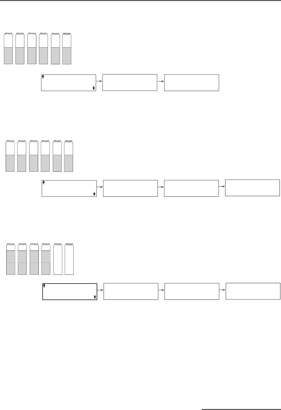
6712FR Refrigerated Sampler
Section 4 Standard Programming
4-7
Figure 4-1 Sample Distribution
SEQUENTIAL
BOTTLES/SAMPLE
SAMPLES/BOT TLE
DISTRIBUTION:
SEQUENTIAL
STANDARD
PROGRAMMING
S
equential
123456
SEQUENTIAL
BOTTLES/SAMPLE
SAMPLES/BOT TLE
2 BOTTLES PER
SAMPLES EVENT (1-24)
DISTRIBUTION:
2 BOTTLES/SAMPLE
STANDARD
PROGRAMMING
Bottles-per-Sample
112233
SEQUENTIAL
BOTTLES/SAMPLE
SAMPLES/BOT TLE
2 SAMPLES PER
BOTTLE (1-50)
DISTRIBUTION:
2 SAMPLES/BOT TLE
STANDARD
PROGRAMMING
Samples-per-Bottle
1357
2468
RUN CONTINUOUSLY?
YES
NO
Each bottle receives one sample from one sample event.
Multiple bottles receive a sample from one sample event.
RUN CONTINUOUSLY?
YES
NO
Each bottle receives a sample from multiple sample events.
RUN CONTINUOUSLY?
YES
NO

6712FR Refrigerated Sampler
Section 4 Standard Programming
4-8
4.6 Start Times It is important to understand the difference between the time at
which you run a program and the program’s start time. Running
a program simply means selecting RUN from the sampler’s main
menu. The start time is the time at which the sampler begins the
program’s first sample interval countdown. The start time is con-
trolled by your selections from the start time screens.
Each program contains start-time settings that tell the sampler
when to begin the program. When programming the sampler, you
can select one of four start time options: NO DELAY TO START,
DELAYED START, CLOCK TIME, or WAIT FOR PHONE CALL.
• Select NO DELAY TO START when you want the
sampler to start as soon as you select RUN.
• Select DELAYED START when you want the sampler to
delay from 1 to 999 minutes before starting the
program.
• Select CLOCK TIME when you want the sampler to
begin the program at a specific time on at least one day
of the week.
• Select WAIT FOR PHONE CALL when you want the
sampler to begin the program after receiving a remote
command to start.
4.6.1 How Do Start Times
Work?
As soon as you select RUN from the main menu, the sampler
checks the program’s start time settings. With a “DELAYED
START” setting, the sampler starts a countdown to the start
time. The period between the time you select RUN and the start
time you’ve specified in the program is called the “delay to start
time.”
When you run a program with “CLOCK TIME” settings, the
sampler also starts a countdown to start time until the day of
week and clock times are met.
The sampler may not collect a sample at the start time. The
sampler must be enabled, and the pacing selected must call for a
sample at start. In any event, the sampler checks the pacing set-
tings and begins the pacing-interval countdown.
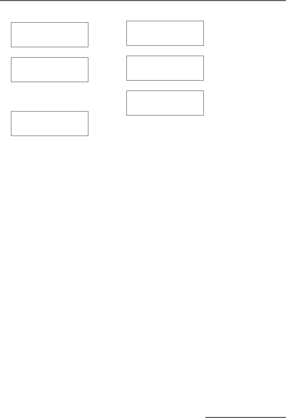
6712FR Refrigerated Sampler
Section 4 Standard Programming
4-9
4.6.2 Sampler
Enable/Disable
Isco flow meters and flow loggers have a programmable
sampler-enable feature that lets them enable (start) or disable
(stop) a program according to certain monitored conditions. For
example these conditions can be level, flow rate, pH, temper-
ature, percent, rainfall, I/O; or a combination of two conditions.
The Model 1640 Liquid Level Actuator can also be used, as well
as any other instrument that can ground the input to pin F.
Grounding the input disables the sampler.
The sampler disregards disable signals during the delay to start
time. However, when the sampler detects a disable signal at the
start time, it suspends the program until it is enabled. The
diagram in Figure 4-2 shows the sampler’s responses.
Delayed Start Screen
1
NO DELAY TO START
DELAYED START
CLOCK TIME
WAIT FOR PHONE CALL
• Select DELAYED START.
2
FIRST SAMPLE
AFTER A
___MINUTE DELAY
(1-999)
• Enter the number of
minutes to delay the
countdown to the first
sample.
3
START FLOW COUNT
AFTER A
__MINUTE DELAY
(1-999)
• The sampler uses this
screen for flow paced
programs.
Clock Start Time Menu
1
NO DELAY TO START
DELAYED START
CLOCK TIME
WAIT FOR PHONE CALL
• Select CLOCK TIME.
2FIRST SAMPLE AT
06:00
• Enter the time of day.
3
SELECT DAYS:
SU MO TU WE TH FR SA
DONE
• Press an arrow key
until the cursor is on
the correct day.
Press↵.
• Repeat until each day
you want is blinking.
• Press an arrow until
DONE blinks. Press ↵.
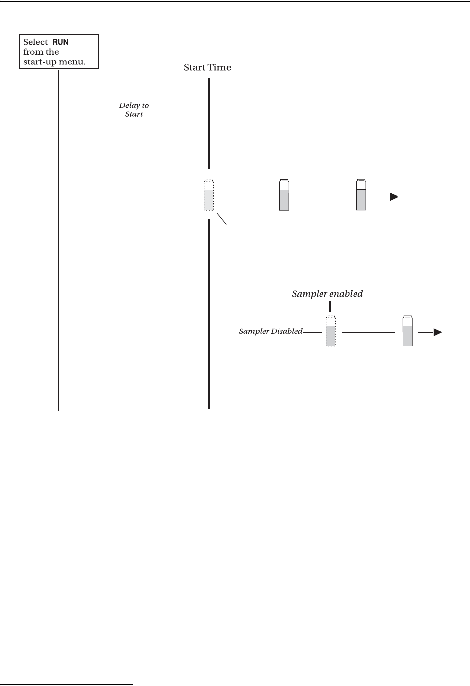
6712FR Refrigerated Sampler
Section 4 Standard Programming
4-10
Figure 4-2 Start Time Diagram
4.7 Running Programs To run a program, select RUN from the main menu. You may also
select YES at the RUN THIS PROGRAM NOW? screen at the
end of the programming screens.
4.7.1 Run Time Screens While running a sampling program the sampler displays a
variety of messages that report the program’s status. For
example, if the sampler has not yet reached the programmed
start time, it displays the scheduled start time as well as the
current time.
Once the program reaches the start time, you can determine the
time of the next sample, the next bottle to receive a sample,
sample distribution, and other information. Other messages
appear while the sampler runs through a sampling cycle and
takes a sample. When the sampler needs to report multiple mes-
sages, it alternates them, displaying each for one to three
seconds.
Sampler disabled at
start time by
signal from pin F
A sample is not taken at start time
if the sampler is disabled. No samples
are taken while disabled.
Sampler enabled at
start time
A sample event at the start time
occurs for time-paced programs.
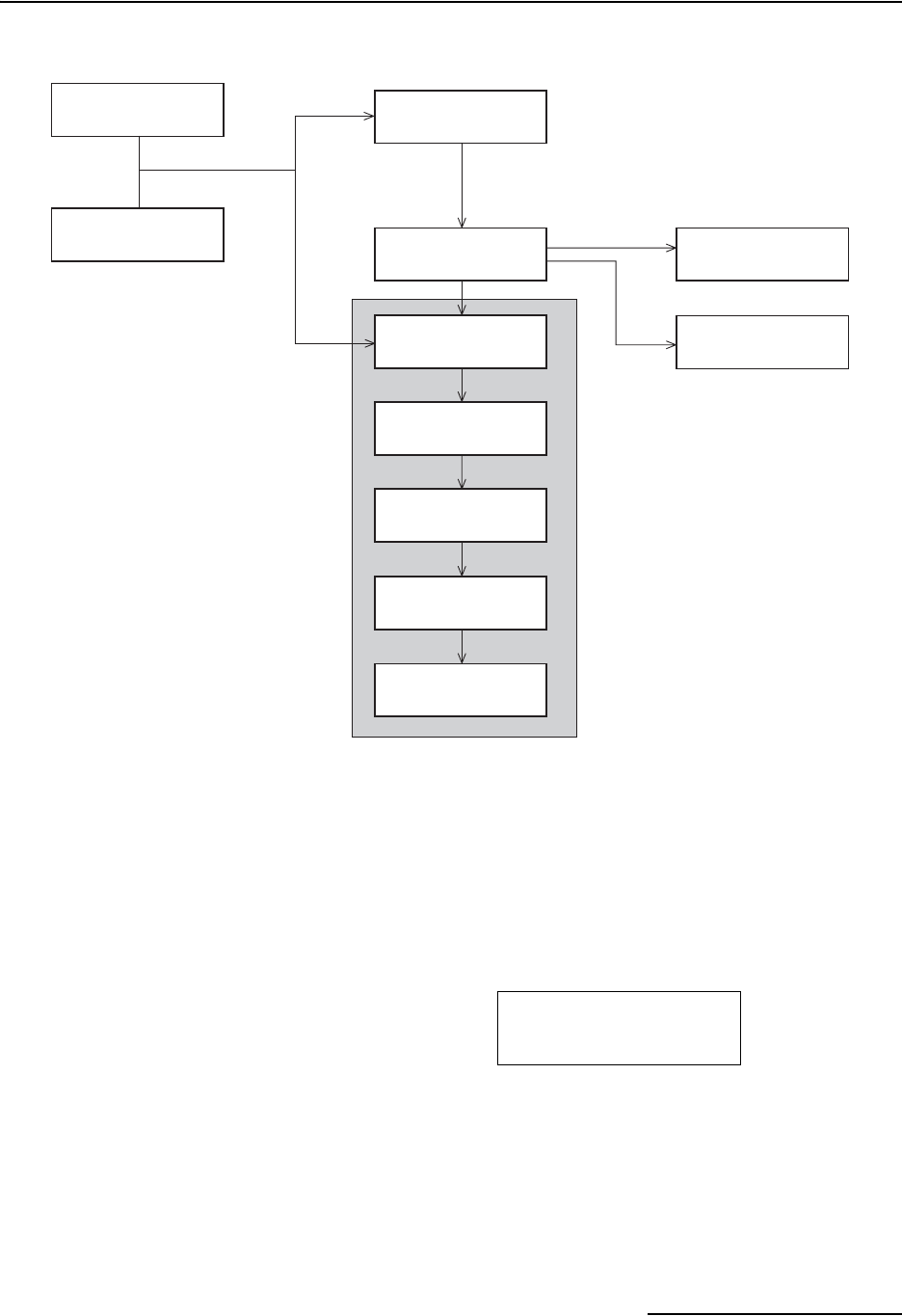
6712FR Refrigerated Sampler
Section 4 Standard Programming
4-11
Figure 4-3 Running a Program
4.7.2 Module Readings Samplers with an attached module display the module’s
readings: pH and temperature for the pH module; level, per-
centage, or flow rate for the 4-20 mA module; level, flow rate, and
flow volume readings for the flow modules; level, velocity, flow
rate, and positive flow volume readings for the area velocity
module. Some module screens will alternate with the sampler
screens.
The Module readings are updated:
• Every second when displaying the reading during
programming.
• Every minute otherwise.
PROGRAMMING COMPLETE
RUN THIS PROGRAM
NOW?
YES NO
ENTER START BOTTLE:
__ (1–MAX)
PLEASE WAIT!
...TESTING
DISTRIBUTOR SYSTEM
OPERATION ERROR
DISTRIBUTOR JAMMED
PROGRAM WILL START
AT 06:00 MO 17–OCT
05:52:22 MO 17–OCT
FATAL ERROR
NO DISTRIBUTOR ARM!
RUN
PROGRAM
VIEW REPORT
OTHER FUNCTIONS
If RUN had been previously Stopped
and no programming changes were made.
Multiple Bottles
Single Bottle
RUN DISPLAYS
If applicable
For the first run using
a 24-bottle base.
If applicable
OR
PURGING
SUCTION LINE
RINSING
SUCTION LINE
SAMPLE 2
IN 00:14:29
PUMPING 250 ml
BOTTLE 2
IN 00:14:39
150 gpm 0.82 ft
00001438200 gal
6712FR Refrigerated Sampler
Section 4 Standard Programming
4-12
An asterisk (*) appears next to the reading if the module was
unable to take a reading. If an asterisk appears, the reading dis-
played is the last available reading. Flow rates will be reported
as zero flow if the error persists for more than five minutes (for a
level or velocity reading that flow is calculated from).
If an entire reading is filled with asterisks, the value exceeds the
number of characters that can be displayed. The sampler stores
the actual reading in memory, so it may be collected later.
For those programs that have delayed or scheduled start times,
the readings will be displayed while waiting for the start time.
Keep in mind that any totalizer values will be reset at the start
time. Module and sonde readings are also displayed after a
program is complete, until a key is pressed.
It is not necessary to run a program to view module or sonde
readings. Real time data can be viewed on the display by
selecting “VIEW REPORT” from the main menu.
4.8 Interrupting a
Running Program
You can interrupt a sampling program by pressing the Stop key
while the sampler is waiting for the next sample event. Pressing
Stop places the sampler into Manual Paused operation and
records a manual pause in the sample event log.
In this state, the sampler allows you to access several functions.
You can modify the program, reset alarms, take a grab sample,
etc., without adversely affecting the running program. Modifying
the program is limited to adjusting the pacing intervals, enable
conditions and sample volume. The basic program structure,
such as the type of pacing, can not be changed.
While in the manual paused state, the sampling program con-
tinues to operate as normal, with the exception of taking
samples. If a sample was to be taken, it is skipped. The sampler
records “sample skipped” in the sample event log and continues
to operate as normal.
The manual paused state displays a scrolling menu with several
options (see example below). Use the Arrow keys to scroll
through the manual paused options and the ↵ key to make a
selection. Return to the running program by selecting resume
program or pressing the Stop key. If you do not make a selection,
the sampler automatically resumes the original sampling
program five minutes after the last key was pressed.
4.8.1 Stop Program This option terminates the running program and records
program stopped in the sample event log. The program cannot be
resumed.
4.8.2 Resume Program Selecting this option will cause the sampler to exit the manual
paused state and return to normal program operation. A manual
resume event will be logged.
BOTTLE 2
IN 00:12:00
***** gpm 5.73 ft
00001457600 gal
← STOP PROGRAM
RESUME PROGRAM
VIEW DATA
GRAB SAMPLE →
Manual Paused Screen

6712FR Refrigerated Sampler
Section 4 Standard Programming
4-13
4.8.3 View Data This option allows you to view the data recorded by the sampler.
See Reports on page 4-18 for more information.
4.8.4 Grab Sample When selected, you will be asked to enter the volume to be
pumped. A sample will then be taken as if it is to be placed into a
container outside the sampler. Do this by removing the pump
tubing from the bulkhead fitting. See Grab Samples on page
4-14. A grab sample event will be logged.
4.8.5 Pump Tube Alarm If the pump tube is changed, this option should be selected to
reset the pump counts on the counter. This will remove the
“WARNING: REPLACE PUMP TUBING” message that may
appear while the program is running. A pump tube replaced
message is logged. See Replacing The Pump Tube in Section 7,
Maintenance.
4.8.6 Calibrate Volume When selected, you will be asked to enter the volume to be
pumped. A sample will then be taken as if it is to be placed into a
container outside the sampler base. Do this by removing the
pump tubing from the bulkhead fitting.
After the sample has been pumped, you will then be asked to
enter the amount actually delivered. Once you have entered the
delivered volume and accepted the calibration, a volume
delivered event will be logged.
4.8.7 Cal/Adj Parameters When the sampler is configured for operation with a module, this
option becomes available. Selecting this option will display the
appropriate level adjustment screens and/or the calibration
screens. If the level is adjusted, an adjusted level event is logged.
If a parameter is calibrated, an appropriate event is logged.
Calibrating a parameter probe will temporarily “turn off” the
partition data storage and the sample enable/disable functions.
These functions are disabled during the calibration and for five
minutes after the program is resumed. During this time,
parameter data normally collected at the data storage interval
will be logged as a 252 error message.
4.8.8 Adjust Pacing This option is available when the running program is paced by
Time, Flow Pulses or Flow Volume. If you select this option, you
are asked to enter a new pacing interval. The sampler logs an
interval changed event.
The original pacing interval continues to count down until you
return the sampler to the running program (select resume
program). If the new pacing interval is less than the original
count remaining, the new interval is used.
If the original count remaining is less than the new pacing
interval, the original count will continue to count down to the
next sample event. Subsequent samples are then paced by the
new interval.
6712FR Refrigerated Sampler
Section 4 Standard Programming
4-14
4.8.9 Adjust Volume Select this option to change the sample volume within the limits
of the currently programmed sample distribution. If you change
a sample volume, a volume changed event is logged.
4.8.10 Power Used The 6712FR has a “fuel gauge” that gives an indication of power
usage. The controller keeps track of how much power has been
consumed since the last time it lost power. If the controller is
powered by an external battery, this fuel gauge can help you
estimate the condition of the battery.
Keep in mind that the sampler has no idea as to how much
charge was originally stored in the battery (or even if a battery is
being used), and therefore has no idea as to the remaining
capacity of its power source.
4.9 Other Functions
In Standard Programming, the “Other Functions” menu screen
includes options for:
• Maintenance (see Section 7).
• Manual Functions (see below).
• Programming Style (see Section 3).
4.10 Manual Functions The manual functions programming screens let you:
• Take grab samples.
• Calibrate sample volumes.
• Operate the pump manually.
• Move the distributor arm.
4.11 Grab Samples Grab samples let you take a single sample on demand, collecting
the sample in an external container (Figure 4-4). Keep in mind:
When the sampler delivers a grab sample, it runs through a com-
plete sampling cycle, using the current settings for volume and
for line rinses or retries. If it is a two-part program, the sampler
uses the settings for part A.
To take a grab sample while the sampler is running a program,
you must interrupt the program by pressing the Stop key.
Restart the program by running it again.
To take a grab sample:
1. Disconnect the pump tube from the bulkhead fitting.
2. Place the end of the tube over a collection container.
3. Follow the steps in Taking a Grab Sample at left.
4. Reconnect the pump tube to the bulkhead fitting.
Other Functions Menu
RUN PROGRAM
VIEW REPORT
OTHER FUNCTIONS
• Select OTHER FUNCTIONS.
MAINTENANCE
MANUAL FUNCTIONS
PROGRAMMING STYLE
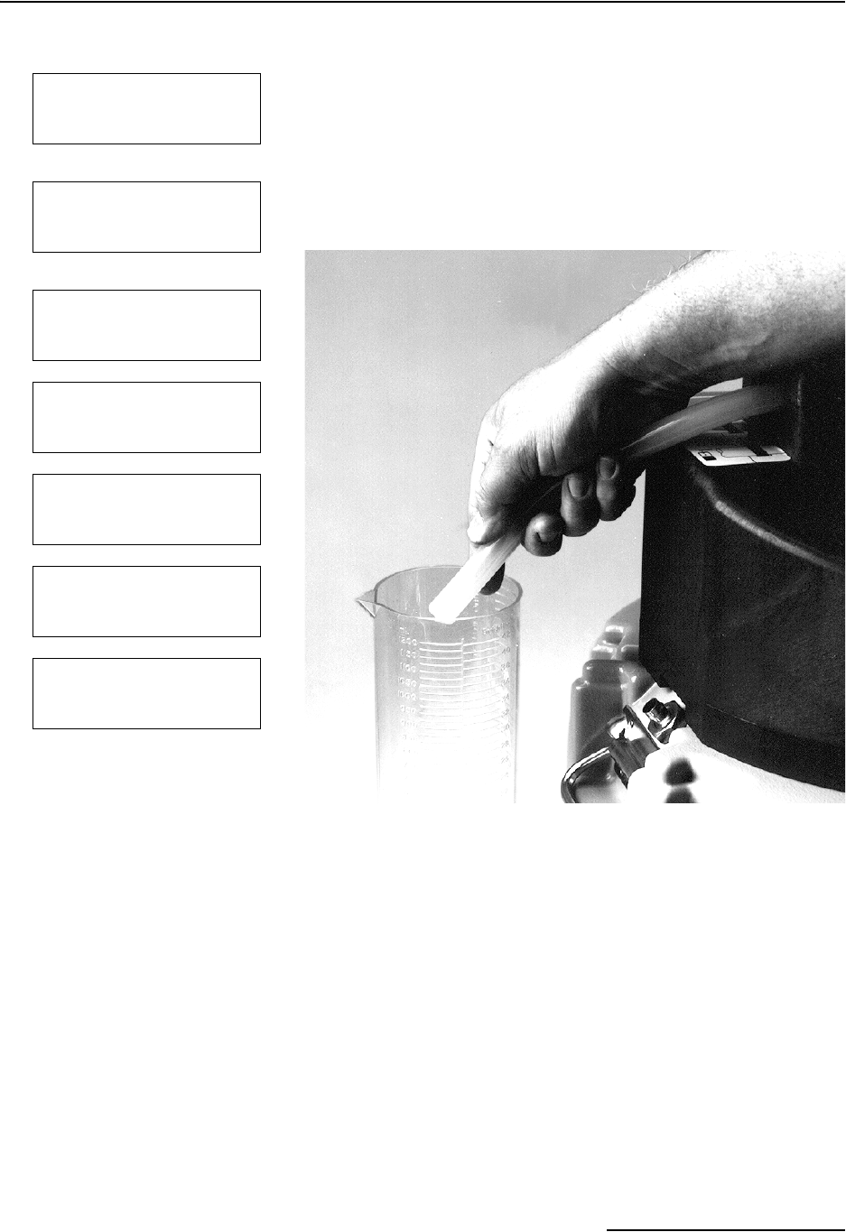
6712FR Refrigerated Sampler
Section 4 Standard Programming
4-15
Figure 4-4 Taking a Grab Sample
4.12 Calibrate Volume The sampler delivers accurate sample volumes without cali-
bration. If you find that sample volumes vary significantly from
the programmed values, first check the suction line for proper
installation. Be sure it slopes continuously downhill to the liquid
source and drains completely after each sampling cycle. Then,
compare the actual length of the suction line to the suction line
length settings in the program to see that they match. Also check
the pump tube for excessive wear and replace it if necessary.
You may want to calibrate when:
• A new pump tube is installed. Run the pump for five
minutes before calibrating.
• The sample source is above the sampler.
• Sampling from pressurized lines (15 PSI Maximum).
Taking a Grab Sample
1
GRAB SAMPLE
CALIBRATE VOLUME
OPERATE PUMP
MOVE DISTRIBUTOR
•Select GRAB SAMPLE
2SAMPLE VOLUME:
___ ml (10-9990)
•Enter the desired volume
3
GRAB SAMPLE
PRESS ↵ WHEN READY!
4
PURGING
SUCTION LINE
5PUMPING 200 ml
6
PURGING
SUCTION LINE
7
GRAB SAMPLE
CALIBRATE VOLUME
OPERATE PUMP
MOVE DISTRIBUTOR
•Press STOP to return to
main menu.
6712FR Refrigerated Sampler
Section 4 Standard Programming
4-16
4.12.1 Calibration Tips • For the best results, calibrate the sampler after it’s
installed on site.
• Use a graduated cylinder for volume measurement.
• The sampler clears the previous calibration setting
when you reinitialize the sampler.
• You cannot calibrate while the sampler is running a
program.
• When the sampler delivers the sample, it runs through a
complete sampling cycle, using the current settings for
volume line rinses and retries. If it is a two part
program, the sampler uses the volume setting for part
A.
To calibrate:
1. Disconnect the pump tube from the bulkhead fitting.
2. Place the end of the tube over a collection container.
3. Follow the steps in Calibrating Sample Volumes in the
margin.
Reconnect the pump tube to the bulkhead fitting.
Calibrating Sample Volumes
1
RUN
PROGRAM
VIEW REPORT
OTHER FUNCTIONS
•Select OTHER FUNCTIONS
2
MAINTENANCE
MANUAL FUNCTIONS
MODULE
HARDWARE
•Select MANUAL FUNCTIONS
3
GRAB SAMPLE
CALIBRATE VOLUME
OPERATE PUMP
MOVE DISTRIBUTOR
•Select CALIBRATE VOLUME
4SAMPLE VOLUME:
___ ml (100-9990)
•Enter the desired volume
5
CALIBRATE VOLUME
PRESS ↵ WHEN READY!
6
PURGING
SUCTION LINE
7PUMPING 200 ml
8
PURGING
SUCTION LINE
9
VOLUME DELIVERED:
____ml
•Measure the volume delivered
and enter the amount here.
10
200 ml
ARE YOU SURE?
YES NO
This screen appears when the
amount you entered in step 9
was more than twice, or less
than half, the programmed
volume.
• Select YES when the volume
delivered matches the volume
displayed on this screen.
• Select NO to enter the volume
delivered.
6712FR Refrigerated Sampler
Section 4 Standard Programming
4-17
4.13 Operating the Pump
You can manually operate the sampler’s pump in the forward or
reverse direction. You can do this to test the pump, draw a large
sample, or purge the suction line.
When you run the pump manually, the sampler reports the
number of pump counts during the pump’s operation. Use this
feature to obtain an estimate of the pump counts required to
purge a nonstandard suction line.
You can also manually run the pump from the main menu. Press
the “1” key and then ↵ to run the pump in reverse. Press the “3”
key and then ↵ to run the pump forward.
CAUTION
Tests indicate that the pump produces sound levels in excess
of 85db at one meter. PROLONGED EXPOSURE TO THIS
SOUND LEVEL COULD RESULT IN HEARING LOSS AND
REQUIRES THE USE OF PROTECTIVE EAR PLUGS.
4.14 Moving the
Distributor Arm
The sampler lets you reposition the distributor arm. Use this
feature to verify a bottle location when installing a bottle kit. You
cannot move the distributor arm while the sampler is running a
program.
CAUTION
DO NOT rotate the distributor arm manually; this will severely
damage the distributor drive gears.
Operating the Pump
GRAB SAMPLE
CALIBRATE VOLUME
OPERATE PUMP
MOVE DISTRIBUTOR
SELECT DIRECTION
PUMP FORWARD
PUMP REVERSE
PURGING. . .
PRESS THE RED ‘STOP’
KEY WHEN DONE
PURGED _____COUNTS
Moving the Distributor
Arm
GRAB SAMPLE
CALIBRATE VOLUME
OPERATE PUMP
MOVE DISTRIBUTOR
• Select MOVE
DISTRIBUTOR
GO TO BOTTLE ____
(1-MAX)
• Enter the bottle number
to which you want to
move the distributor
NOW AT BOTTLE ____
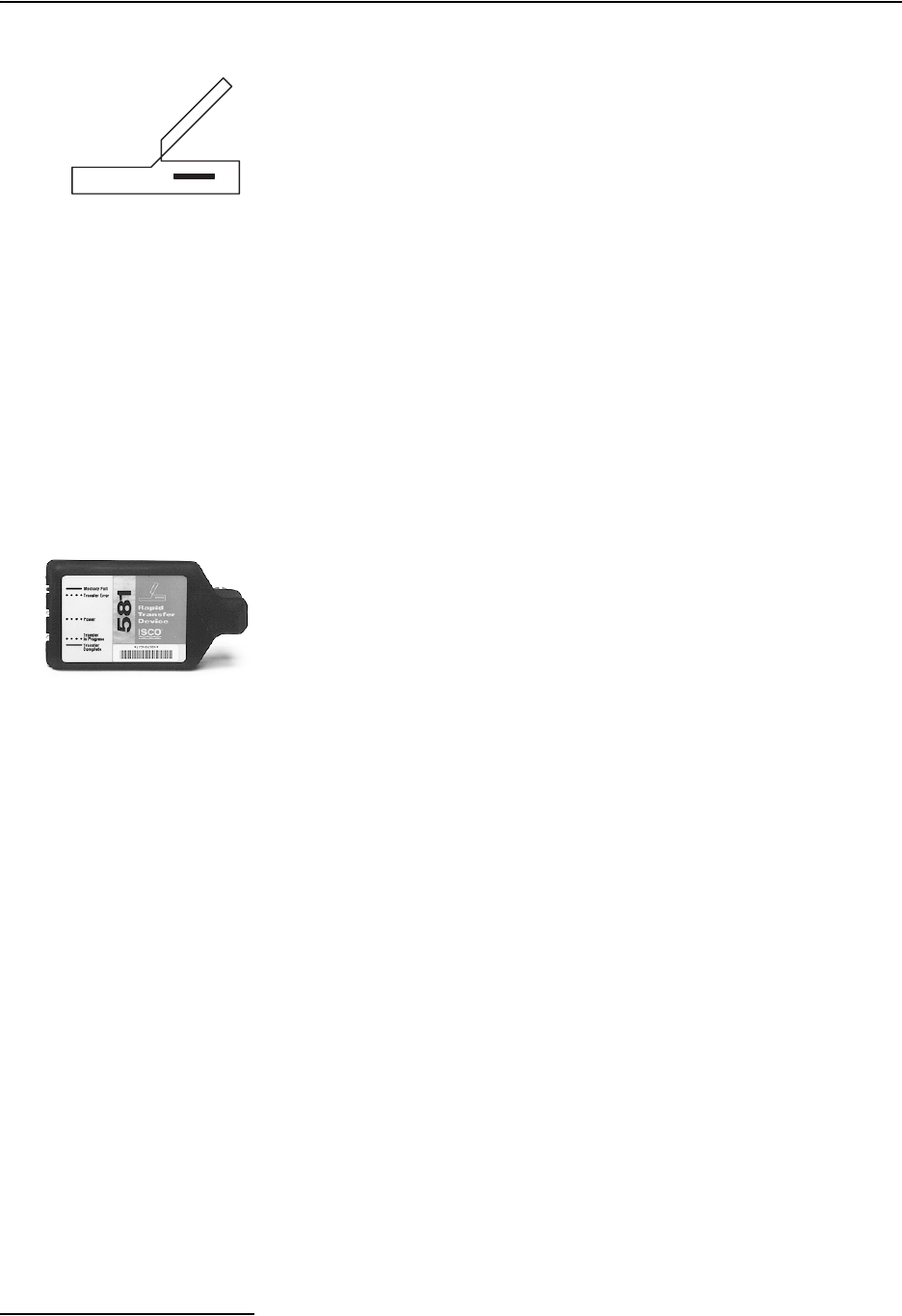
6712FR Refrigerated Sampler
Section 4 Standard Programming
4-18
4.15 Reports
The 6712 records a variety of data while running a sampling
program. It uses the data to produce four reports:
• The Program Settings report, listing the program
settings.
• The Sampling Results report, listing the program
settings, time of samples and other program events.
• The Combined Results report, combining the sample
event times with rainfall or module data.
• The Summary report, listing daily summaries of data
collected. The Summary report may be rainfall and/or
module data.
The sampler stores the data for each report in memory where
they remain until you select RUN. Selecting RUN clears the
memory so that it can store the data from the next program.
4.15.1 Collecting Reports There are a number of ways to collect the reports:
View reports (program settings, sampling results, and abbre-
viated summary reports) on the sampler’s display.
Collect the reports (except for summary reports) with an Isco 581
RTD and use a computer running flowlink or samplink to
transfer the reports from the RTD to a file on the computer.
Collect the reports (except for summary reports) with an IBM PC
or compatible computer running flowlink.
Collect the reports with and IBM PC or compatible computer
running samplink.
4.15.2 Viewing the Data
Because the display area is small, the data on the reports will be
displayed a little differently from the data that is transferred to
and viewed on your computer.
• For the Sampling Report, the sampler displays each
program event, one at a time.
• For the Module and Rainfall Data reports, it displays
daily summaries, instead of the full reports available
with the rtd, Flowlink, or Samplink.
If you select Sampling Report or Rainfall (step 3 in Viewing Data,
shown in the margin), the sampler begins displaying the report
data. The sampler advances automatically through the report
items, displaying each item briefly. While the sampler advances
automatically through the displays:
• Stop the automatic displays by pressing Stop once.
Then, use the arrow keys to move manually through the
report.
Interrogator
581 RTD
6712FR Refrigerated Sampler
Section 4 Standard Programming
4-19
• Return to the main menu by pressing Stop twice.
At the end of the report, the sampler leaves the last item dis-
played until you press:
• the arrow keys to move forward or backward manually
through the report.
• Stop to return to the main menu.
•↵ to start the automatic displays again.
If you select Module Data in step 3, the sampler displays the
screen shown in step 4. Select the Daily Summary option and the
sampler displays the stored data just as the Sampling Report
was described above. Selecting the current readings option
causes the sampler to display real-time readings. When there are
multiple screens, they will be displayed alternately. You can
quickly advance through the screens by pressing an arrow key or
↵. Pressing Stop exits the Current Readings mode.
4.15.3 Configuring Reports
The Configure Reports option lets you specify which of the Sam-
pling Reports will be included in any output request. Each
sampler is shipped with the option flowlink report selected.
The Samplink Report and Flowlink Report options allow you to
tailor the output to the Isco software used to collect the reports.
The Samplink Report option provides the Sampling Reports, but
disables the output of the detailed partition data.
Flowlink Report provides the Sampling Reports and the detailed
partition data. Selecting the Flowlink Report option enables the
output of the detailed partition data so Flowlink can add the data
to the site’s database file.
When you are familiar with the available Sampling Reports, you
may want to specify an output containing only the specific data
you require. The Custom Report option will allow selection of
detailed data. Data collection time and storage space may be
optimized using this option.
Viewing Data
1
RUN
PROGRAM
VIEW REPORT
OTHER FUCTIONS
• Select VIEW REPORT.
2
VIEW DATA
SYSTEM IDs
CONFIGURE REPORTS
• Select VIEW DATA.
3
SELECT DATA TO VIEW:
SAMPLING REPORT
MODULE DATA
RAINFALL DATA
• Select a report or data type.
4
VIEW:
DAILY SUMMARY
CURRENT READINGS
• Select DAILY SUMMARY to view
the stored data, or CURRENT
READINGS to view real-time
data.
1
RUN
PROGRAM
VIEW REPORT
OTHER FUCTIONS
• Select VIEW REPORT.
2
VIEW DATA
SYSTEM IDs
CONFIGURE REPORTS
• Select CONFIGURE REPORTS
3
SAMPLINK REPORT
FLOWLINK REPORT
CUSTOM REPORT
ALL REPORTS
• Select the option that matches
your data collection software,
or tailor the output according
to the reports needed.

6712FR Refrigerated Sampler
Section 4 Standard Programming
4-20
4.15.4 Sampling Results
Report
As the sampler runs a program, it records the program’s events.
Program events include such items as sample events, program
enables and disables, power losses, and so on. Table 4-3 lists each
event with a short description. You can view the report by fol-
lowing the steps in Viewing the Data on page 4-18 or print the log
as the Sampling Results report.
In the text file version of the report, sample-event entries include
the time of the event as well as the sample and bottle numbers.
The sample column contains the sample number deposited into
the bottle. This information reflects the distribution selected for
the program.
The letters in the Source columns are codes for the cause of the
event. The letters in the Error column are codes for the causes of
missed samples. The source and error codes appear with expla-
nations at the end of the report. A list of codes appears in Table
4-3.
The last column in the Sampling Results report records the
pump counts for the sample event. Large variations in pump
counts from event to event indicate fluctuating heads, a relocated
suction line, or a temporarily clogged strainer.
4.15.5 Combined Results
Report
At the time of each sample event, the sampler records the
readings from each connected module, rain gauge, or SDI-12
sonde. The Combined Results Report presents the event time,
sample and bottle number, and the respective readings from the
device.
For flow modules, the readings are level and flow rate. For the
pH module, the readings are temperature and pH. For the rain
gauge and SDI-12 Sonde, the readings vary according to the
selections enabled during the hardware setup in extended pro-
gramming. When recording four or more sonde parameters, the
Combined Results report will exceed the standard 40 character
width. To read the additional columns, the data must be collected
with Flowlink 4 for Windows software.
4.15.6 Summary Report This report summarizes the rain gauge or module data. The
types of readings are the same as those available to the Com-
bined reports. The sampler compiles the data to present a daily
total, the day’s average, maximum, and minimum reading, and a
listing of hourly averages. The sampler then graphs the day’s
readings.
6712FR Refrigerated Sampler
Section 4 Standard Programming
4-21
Table 4-3 Reports: Program Events, Source Codes, and Error Codes
* Indicates events and codes that occur in Standard Programming
Program Events (listed in the order that they most likely would occur)
*Program Run The sampler ran the sampling program.
*Program Started The sampler started the sampling program.
*Program Enabled (Disabled) The sampler was enabled or disabled according to program settings or an external
instrument.
‘A’/’B’ Enabled (Disabled) Program part ‘A’ or ‘B’ was enabled or disabled according to the program’s settings.
Sample A sample was taken as programmed. (See Source Codes and Error Codes in this
table.)
*Sample Switch Time A sample was taken at programmed switch time.
*Program Done The sampler finished the sampling program.
‘A’/’B’ Done The sampler finished program part ‘A’ or ‘B’.
*Manual Pause Stop was pressed during the program to enter the Manual Paused state.
*Program Stopped You selected Stop from the manual paused options, terminating the program.
*Grab Sample A grab sample was taken while in the Manual Paused state.
Pump Tube Replaced The pump tube alarm was reset while in the Manual Paused state.
Calibrate Volume The volume was calibrated.
Calibrate SDI Parameter An SDI-12 sonde or module parameter was calibrated.
*Adjusted Pacing The pacing interval was changed while in the Manual Paused state.
*Volume Changed Sample volume was changed while in the Manual Paused state.
Adjust Enable Sampler enable thresholds were changed while in the Manual Paused state.
Reset Rain History The rain history was reset.
Adjust Suction Head The suction head was changed while in the Manual Paused state.
*Manual Resume The resume program option was selected from the Manual Paused state.
Program Paused (Resumed) The program reached a programmed pause or resume time.
‘A’/’B’ Paused (Resumed) Program part ‘A’ or ’B’ reached a programmed pause or resume time.
*Power Failed The power source was disconnected.
*Power Restored The power source was reconnected.
Alarm Occurred An alarm occurred.
Alarm Acknowledged An alarm was acknowledged.
*Missed Password The password was missed.
6712FR Refrigerated Sampler
Section 4 Standard Programming
4-22
Figures 4-5, 4-6, 4-7, 4-8, and 4-9 show examples of reports con-
figured to show program settings, sampling results, combined
results, and a summary report.
(The Source and Error Codes Listed below refer to why a sample was taken and what happened while it was being
taken.)
Source Codes
*C Calibrate sample Sample volume delivered during calibration.
*D Disable Sample event at disable time.
*E Enable Sample event at enable time.
Ev Event Event-paced sample event.
*F Flow Flow-paced sample event.
*G Grab sample Sample volume delivered as a grab sample.
M Command driven sample A command driven sample.
PH Phone command Phone command sample.
R Resume Sample event at resume time.
*S Start Sample event at start time.
Sw Switch time Sample event at switch time.
TO Time Override Sample event at bottle-switch time.
*T time Time-paced sample event.
Error Codes
*DJ Distributor Jammed The distributor jammed.
*IP sample in progress Sample in progress when report was printing.
*L pump latch open Unable to take sample because the pump band was opened.
*ND no distributor arm There is no distributor arm or the stop is damaged.
*NL No Liquid Detected The sampler was unable to detect liquid.
LF Not enough flow Not enough flow for the minimum sample volume entered for samples with volumes
proportional to flow.
*NM No More Liquid After the sampler detected liquid and while the sample was being taken, the liquid
detector stopped detecting liquid.
M Bottle Full The composite bottle is full.
*O Sampler Shut Off The sampler was turned off with the On-Off key during the sample event.
Ov Probable Overflow The sampler was directed to take a sample that would not fit into the bottle. Occurs
for flow paced, time override programs only.
*P Power Failed The power supply failed during the sample event. Note: Power failures during five
consecutive sample events results in a LOW BATTERY shut-down.
*PJ Pump Jammed The pump jammed.
*Sk Sample Skipped Sample not taken.
*US User Stopped You pressed the Stop key during the sample event.
Table 4-3 Reports: Program Events, Source Codes, and Error Codes (Continued)

6712FR Refrigerated Sampler
Section 4 Standard Programming
4-23
Figure 4-5 Report: Program Settings
SAMPLER ID# 3687447734 06:32 19-DEC-02
Hardware: A0 Software: 1.02
*********** PROGRAM SETTINGS ***********
----------
SITE DESCRIPTION:
"FACTORY051"
----------
UNITS SELECTED:
FLOW RATE: cfs
FLOW VOLUME: Mgal
----------
BUBBLER MODULE:
WEIR
90
V-NOTCH
----------
24, 1000 ml BTLS
10 ft SUCTION LINE
----------
PACING:
TIME, EVERY
0 HOURS, 15 MINUTES
----------
DISTRIBUTION:
SEQUENTIAL
----------
200 ml SAMPLES
----------
5 MINUTE DELAY TO
FIRST SAMPLE
----------------------------------------

6712FR Refrigerated Sampler
Section 4 Standard Programming
4-24
Figure 4-6 Report: Sampling Results
SAMPLER ID# 3687447734 06:32 19-DEC-02
Hardware: A0 Software: 1.02
*********** SAMPLING RESULTS ***********
SITE: FACTORY051
Program Started at 15:03 WE 18-DEC-02
Nominal Sample Volume = 200 ml
COUNT
TO
SAMPLE BOTTLE TIME SOURCE ERROR LIQUID
------- ------ ---- -- -- ------
15:03 PGM ENABLED
1,1 1 15:03 S 250
1,1 2 15:18 T 247
1,1 3 15:33 T 247
1,1 4 15:48 T 249
1,1 5 16:03 T 247
1,1 6 16:18 T 247
1,1 7 16:33 T 247
1,1 8 16:48 T 248
1,1 9 17:03 T 237
1,1 10 17:18 T 236
1,1 11 17:33 T 237
1,1 12 17:48 T 241
1,1 13 18:03 T 238
1,1 14 18:18 T 236
1,1 15 18:33 T 237
1,1 16 18:48 T 236
1,1 17 19:03 T 242
1,1 18 19:18 T 237
1,1 19 19:33 T 235
1,1 20 19:48 T 238
1,1 21 20:03 T 237
1,1 22 20:18 T 237
1,1 23 20:33 T 236
1,1 24 20:48 T 230
20:48 PGM DONE 19-DEC
SOURCE S ==> START
SOURCE T ==> TIME
----------------------------------------

6712FR Refrigerated Sampler
Section 4 Standard Programming
4-25
Figure 4-7 Report: Combined Results
SAMPLER ID# 3687447734 06:32 19-DEC-02
Hardware: A0 Software: 1.02
BUBBLER MODULE: 2215419583
Hardware: A00000 Software: 1.07
*********** COMBINED RESULTS ***********
SITE: FACTORY051
Program Started at 15:03 WE 18-DEC-02
Nominal Sample Volume = 200 ml
FLOW TOTAL
LEVEL RATE FLOW
SAMPLE BOTTLE TIME ft cfs Mgal
------- ------ ---- ----- ----- -------------
1,1 1 15:03 0.009 2.495 000000.000
1,1 2 15:18 0.012 2.576 000000.017
1,1 3 15:33 0.012 2.666 000000.035
1,1 4 15:48 0.012 2.773 000000.053
1,1 5 16:03 0.012 2.773 000000.072
1,1 6 16:18 0.012 2.798 000000.091
1,1 7 16:33 0.012 2.798 000000.109
1,1 8 16:48 0.012 2.798 000000.128
1,1 9 17:03 0.012 2.751 000000.147
1,1 10 17:18 0.012 2.773 000000.166
1,1 11 17:33 0.009 2.798 000000.185
1,1 12 17:48 0.012 3.728 000000.207
1,1 13 18:03 0.012 3.728 000000.232
1,1 14 18:18 0.012 3.728 000000.257
1,1 15 18:33 0.009 3.728 000000.282
1,1 16 18:48 0.012 5.273 000000.317
1,1 17 19:03 0.012 5.239 000000.353
1,1 18 19:18 0.012 6.651 000000.397
1,1 19 19:33 0.009 6.651 000000.442
1,1 20 19:48 0.009 6.651 000000.486
1,1 21 20:03 0.012 6.651 000000.531
1,1 22 20:18 0.012 6.651 000000.576
1,1 23 20:33 0.009 3.404 000000.612
1,1 24 20:48 0.012 3.425 000000.634
-----------------------------------------------

6712FR Refrigerated Sampler
Section 4 Standard Programming
4-26
Figure 4-8 Report: Combined Results (continued)
SAMPLER ID# 3687447734 06:32 19-DEC-02
Hardware: A0 Software: 1.02
*********** COMBINED RESULTS ***********
SITE: FACTORY051
Program Started at 15:03 WE 18-DEC-02
Nominal Sample Volume = 200 ml
FR-TEMP
SAMPLE BOTTLE TIME C
------- ------ ---- ----
NO FR-TEMPERATURE
----------------------------------------
SAMPLER ID# 3687447734 06:32 19-DEC-02
Hardware: A0 Software: 0.01.0127
*********** COMBINED RESULTS ***********
SITE: FACTORY051
Program Started at 15:03 WE 18-DEC-02
Nominal Sample Volume = 200 ml
SAMPLE BOTTLE TIME
------- ------ ----------- ------ ----
NO RAIN GAUGE
----------------------------------------
SAMPLER ID# 3687447734 06:32 19-DEC-02
Hardware: A0 Software: 0.01.0127
SDI-12 DATA
*********** COMBINED RESULTS ***********
SITE: FACTORY051
Program Started at 15:03 WE 18-DEC-02
Nominal Sample Volume = 200 ml
NO SDI-12 SONDE
----------------------------------------

6712FR Refrigerated Sampler
Section 4 Standard Programming
4-27
Figure 4-9 Report: Summary
SAMPLER ID# 3687447734 16:41 20-DEC-02
Hardware: A0 Software: 1.02
BUBBLER MODULE: 2215419583
Hardware: A00000 Software: 1.07
SITE: FACTORY051
Summary Report for 19-DEC-02 (TH)
Day's Flow: 000000.054 Mgal
Average Flow Rate: 0.4437 cfs
07:20 Minimum Flow Rate: 0.0237 cfs
13:25 Maximum Flow Rate: 7.0207 cfs
Hourly Average Flow Rate:
00:00-01:00: NO DATA
01:00-02:00: NO DATA
02:00-03:00: NO DATA
03:00-04:00: NO DATA
04:00-05:00: NO DATA
05:00-06:00: NO DATA
06:00-07:00: NO DATA
07:00-08:00: NO DATA
08:00-09:00: 2.519 cfs
09:00-10:00: 2.747 cfs
10:00-11:00: 2.791 cfs
11:00-12:00: 3.456 cfs
12:00-13:00: 5.385 cfs
13:00-14:00: 6.651 cfs
14:00-15:00: 2.591 cfs
15:00-16:00: 1.593 cfs
16:00-17:00: NO DATA
17:00-18:00: NO DATA
18:00-19:00: NO DATA
19:00-20:00: NO DATA
20:00-21:00: NO DATA
21:00-22:00: NO DATA
22:00-23:00: NO DATA
23:00-24:00: NO DATA
*---+---+---+---+---+---+*
8.00 + +
I I
I I
I # I
I # I
6.00 + # +
I # I
I ## I
I ## I
I ## I
4.00 + ## +
I ### I
I ### I
I ##### I
I ####### I
2.00 + ####### +
I ####### I
I ######## I
I ######## I
I ######## I
0.00 + ######## +
*---+---+---+---+---+---+*
Hour Ending: 08: 16: 24:
Units are 'cfs'
6712FR Refrigerated Sampler
Section 4 Standard Programming
4-28
4.16 System IDs
In addition to viewing report data and configuring reports, the
View Report option on the main menu lets you view system iden-
tification information.
The sampler reports the sampler model number, ID (identifi-
cation number), and software version number as system identifi-
cation notes. The sampler also reports the same information for
an attached module.
The model and ID numbers remain unchanged through the life of
the sampler. The ID numbers appear on the sampler’s reports
and in files created by flowlink and samplink when they inter-
rogate the sampler. The software packages use the ID number to
make sure that data from different samplers is not combined in
the same file.
The software version number changes when your sampler’s
software is updated.
The system will also list any software options that you have acti-
vated on your unit. These software options are discussed in
Section 5.
4.17 Programming for 700
Series Modules
The bay on the controller’s side accepts any of Teledyne Isco’s 700
Series Modules. These modules are optional accessories that are
not required for operation of the 6712. However, the modules
offer an economical way to combine flow-rate or parameter moni-
toring with sampling.
The programming of these modules is integrated with the pro-
gramming of the sampler, so attachment of a module will cause
different screens to be displayed, depending on the type of
module and the selections you make while programming.
Two modules that are commonly used are the 730 Bubbler
Module, which monitors a flow stream’s level and flow rate, and
the 750 Area Velocity Module for monitoring a flow stream’s
level, velocity, and flow rate. The following sets of screens give
you an example of what screens you might see while pro-
gramming the sampler and module. Refer to Table 4-1 (which
does not have a module attached) at the beginning of this section
to compare the sequence of screen displays.
System IDs
RUN
PROGRAM
VIEW REPORT
OTHER FUNCTIONS
• Select VIEW REPORT.
VIEW DATA
SYSTEM IDs
CONFIGURE REPORTS
• Select SYSTEM IDs.
SAMPLER
6712 ID __________
HARDWARE: __
SOFTWARE: __
• Displayed briefly
[MODULE TYPE]
[MODEL #] ID: __________
HARDWARE: __
SOFTWARE: __
• Displayed briefly
SOFTWARE OPTIONS
[Options List]
• Press STOP to return to the
main menu.
6712FR Refrigerated Sampler
Section 4 Standard Programming
4-29
CAUTION
Most Isco accessories and interfacing equipment are not certi-
fied for us in hazardous locations as defined by the National
Electrical Code. Check applicable guidelines, codes, and regu-
lations of federal, state, city, and county agencies. Refer to
Appendix C in the back of this manual for more safety informa-
tion.
Table 4-4 Programming Example With 730 Module Installed
1
MODULE INSERTED---
DOWNLOAD DATA NOW
OR LOSE ALL DATA!
DONE
With the sampler off, insert the module in the bay on the controller.
Turn the sampler on by pressing the On/Off key. Press ↵.
Download stored data, if you want to keep it. Pressing DONE erases it and
advances to the next screen.
2
6712 SAMPLER
STANDARD PROGRAMMING
For HELP at any
screen press ? key.
This screen will now appear for 8 seconds.
3
RUN
PROGRAM
VIEW REPORT
OTHER FUNCTIONS
The option PROGRAM will be blinking. Press ↵.
4
SITE DESCRIPTION:
“FACTORY051“
CHANGE?
YES NO
The option NO will be blinking. Press ↵.
For the purposes of this example, it isn’t necessary to change the description.
5
SELECT UNITS FOR
FLOW RATE:
cfs gps gpm Mgd
lps m3s m3h m3d
Select the desired units for the flow rate. For this example, choose cfs.
Press ↵.
6
SELECT UNITS FOR
FLOW VOLUME:
cf gal Mgal
m3 lit
Select the desired units for the flow volume. For this example, choose Mgal.
Press ↵.
7PROGRAM MODULE?
YES NO
Select YES to program the module.
8
MODE OF OPERATION:
FLOWMETER
LEVEL ONLY
If you choose Flowmeter, proceed to screen #9 below.
If you choose LEVEL ONLY, proceed to screen #12.
9
WEIR FLUME
DATA POINTS
EQUATION MANNING
FLOW-INSERT
When you select Flowmeter, you will have several options for performing the
flow conversion.
For this example, choose Weir. Press ↵.

6712FR Refrigerated Sampler
Section 4 Standard Programming
4-30
10
V-NOTCH
RECTANGULAR
CIPOLLETTI
For this example, choose V-Notch. Press ↵.
11
V-NOTCH WEIR ANGLE:
120 90 60
45 30 22.5
For this example, choose a Weir angle of 90. Press ↵.
12
CURRENT LEVEL IS
__.__ ft
ADJUST LEVEL TO
__.__ ft
The current level will be displayed. Enter an adjustment if needed. If the
adjustment is different by more than 0.50 ft, you will be prompted “ARE YOU
SURE? YES NO” Choose NO to re-enter; select YES if correct. Press ↵.
13 NUMBER OF BOTTLES:
12481224
Select the number of bottles in your bottle kit by pressing either arrow key
until the correct number blinks. Press ↵. For this example, select 24.
14 BOTTLE VOLUME IS
1000 ml (300-30000)
Type the volume for the bottles in your kit. For this example, 1000 is correct,
so simply press ↵.
15 SUCTION LINE LENGTH
IS 10 ft
(3-99)
Type the length of the suction line, then press ↵.
If you change the length, the sampler will display a message,
“PLEASE WAIT!. . . GENERATING PUMP TABLES.”
16 TIME PACED
FLOW PACED
Select FLOW PACED.
If the module is being used as a flowmeter, you will see screen #17a.
If the module is being used for level only, you will see screen #17b.
17a
FLOW BETWEEN
SAMPLE EVENTS:
0.075 Mgal
(0.001 - 99999)
If the module is being used as a flowmeter, choose the amount of flow
between sample events.
17b
FLOW BETWEEN
SAMPLE EVENTS:
2 PULSES (1-9999)
If the module is being used for level only, enter the number of pulses
between sample events.
18
SEQUENTIAL
BOTTLES/SAMPLE
SAMPLES/BOTTLE
Select BOTTLES/SAMPLE.
19 2 BOTTLES PER
SAMPLE EVENT (1-24)
Enter 2.
20
RUN CONTINUOUSLY?
YES NO
Select NO.
21 SAMPLE VOLUME:
250 ml (10-1000)
Enter 250.
Table 4-4 Programming Example With 730 Module Installed (Continued)
6712FR Refrigerated Sampler
Section 4 Standard Programming
4-31
22
NO DELAY TO START
DELAYED START
CLOCK TIME
WAIT FOR PHONE CALL
Select CLOCK TIME.
23 START FLOW COUNT AT:
06:00
Enter 6, then enter 0.
This is the time at which the sampler will start the pacing countdown.
24
SELECT DAYS:
SU MO TU WE TH FR SA
DONE
Select MO, WE, and FR.
Use the arrow keys and ↵ to select MO, WE, and FR. When the correct days
are blinking, select DONE and press ↵.
25
PROGRAMMING COMPLETE
RUN THIS PROGRAM
NOW?
YES NO
Select NO.
Table 4-4 Programming Example With 730 Module Installed (Continued)
Table 4-5 Programming Example With 750 Module Installed
1
MODULE INSERTED---
DOWNLOAD DATA NOW
OR LOSE ALL DATA!
DONE
With the sampler off, insert the module in the bay on the controller.
Turn the sampler on by pressing the On/Off key. Press ↵. Download stored
data, if you want to keep it. Pressing DONE erases it and advances to the
next screen.
2
6712 SAMPLER
STANDARD PROGRAMMING
For HELP at any
screen press ? key.
This screen will now appear for 8 seconds.
3
RUN
PROGRAM
VIEW REPORT
OTHER FUNCTIONS
The option PROGRAM will be blinking. Press ↵.
4
SITE DESCRIPTION:
“FACTORY051“
CHANGE?
YES NO
The option NO will be blinking. Press ↵.
For the purposes of this example, it isn’t necessary to change the description.
5
SELECT UNITS FOR
FLOW RATE:
cfs gps gpm Mgd
lps m3s m3h m3d
Select the desired units for the flow rate. For this example, choose cfs.
Press ↵.
6
SELECT UNITS FOR
FLOW VOLUME:
cf gal Mgal
m3 lit
Select the desired units for the flow volume. For this example, choose Mgal.
Press ↵.
7
SELECT UNITS FOR
VELOCITY:
fps mps
Select the desired units for the flow velocity. For this example, choose fps.
Press ↵.
6712FR Refrigerated Sampler
Section 4 Standard Programming
4-32
8PROGRAM MODULE?
YES NO
Select YES to program the module.
9
MODE OF OPERATION:
FLOWMETER
LEVEL AND VELOCITY
The 750 can have two different modes of operation: Flowmeter or Level and
Velocity.
For this example, choose Flowmeter. Press ↵.
10
FLOW CALCULATION:
AREA * VELOCITY
LEVEL TO FLOW RATE
When you select Flowmeter, you will have two options for performing the
flow conversion: Area * Velocity or Level to Flow Rate.
For this example, choose Area * Velocity. Press ↵.
11
LEVEL TO AREA:
CHANNEL SHAPE
DATA POINTS
For this example, choose Channel Shape. Press ↵.
12
ROUND PIPE
U-CHANNEL
RECTANGULAR CHANNEL
TRAPEZOIDAL CHANNEL
For the channel shape, select Round Pipe. Press ↵.
13
ROUND PIPE
DIAMETER = 2.00 ft
Enter the diameter of the round pipe. Press ↵.
14
CURRENT LEVEL IS
__.__ ft
ADJUST LEVEL TO
__.__ ft
The current level will be displayed. Enter an adjustment if needed. If the
adjustment is different by more than 0.50 ft, you will be prompted “ARE YOU
SURE? YES NO” Choose NO to re-enter; select YES if correct. Press ↵.
15 ZERO LEVEL OFFSET:
_.___ ft
Enter the amount of zero level offset. Press ↵.
16
MAXIMUM DEPTH FOR
VELOCITY MEASUREMENT
2” 3” 4”
(This screen is applicable for standard-sized probes only.)
Select the maximum depth for the velocity measurement. Press ↵.
17 NUMBER OF BOTTLES:
12481224
Select the number of bottles in your bottle kit by pressing either arrow key
until the correct number blinks. Press ↵.
From this point forward, the screens will be the same as in Table 4-2.
Table 4-5 Programming Example With 750 Module Installed (Continued)
5-1
6712FR Refrigerated Sampler
Section 5 Extended Programming
The 6712FR Sampler has two sets of programming screens. The
first set, called standard programming screens, lets you set up
typical sampling programs easily and efficiently. The second set,
extended programming screens, lets you create sophisticated
programs for complex sampling applications.
All of the sampling features available with standard pro-
gramming screens, discussed in Section 4, are available with
extended programming screens. However, the extended screens
provide several additional features and some screen display dif-
ferences which are discussed in this section. The menu flow-
charts for both sets of programming screens are in Appendix A,
Menu Flowcharts.
Note
This section assumes that you have read, and are familiar
with, the instructions in Section 4, Standard Programming!
5.1 Extended and
Standard Mode
The sampler is shipped with factory default settings in standard
programming mode when you first turn the sampler on. The
start-up screen tells you which programming mode the sampler
is currently using. You can switch between programming modes
by entering a numerical command at the main menu:
At the main menu type 6712.2 to enter extended programming
mode.
At the main menu type 6712.1 to enter standard programming
mode.
5.2 One-Part and
Two-Part Programs
Extended programming lets you set up a “one-part” program or a
“two-part” program. One-part programs let you fill all bottles of
the tub with one set of pacing, distribution, and enable settings.
Two-part programs add an additional set of extended pacing, dis-
tribution, and enable screens to the sampling program. Each set
of screens is called a program part. The program parts are simply
called part ‘A’ and part ‘B’. Both parts share the program settings
for suction-line length, suction head, and rinses and retries. They
also share one start-time setting.
RUN “EXTENDED 1”
PROGRAM
VIEW REPORT
OTHER FUNCTIONS
Main Menu for Extended Mode

6712FR Refrigerated Sampler
Section 5 Extended Programming
5-2
Each part has its own group of bottles. Because settings for each
part are independent of each other, the sampler, when running a
two-part program, fills each bottle group as if they were being
filled by two different programs. Two-part programs finish when
both parts are done.
Two-part programming is ideal for sampling storm events. Many
storm-water run-off monitoring permits require a first-flush grab
sample within the first 30 minutes of the storm event and
flow-paced samples during the remainder of the event. With a
two-part program, you can set up part ‘A’ for the first-flush
sample and part ‘B’ for the remainder. Table 5-2 shows a
storm-water sampling program.
5.3 Storage for Extended
Programs
The sampler stores five sampling programs: one standard and
four extended. Program storage eliminates the need to
reprogram the sampler with frequently used settings. This
feature is especially useful for complex extended programs such
as two-part programs or programs with many nonuniform-time
settings.
Teledyne Isco ships the sampler to you with factory programs
that you can modify to suit your own needs. All four extended
programs are identical to each other.
The stored programs will also save your 700 Series Module
program settings and any sampler enable conditions using rain
gauge data or SDI-12 sonde parameters. These program settings
remain as long as you do not change the type of module, or
change the rain gauge or SDI-12 Hardware Setup.
5.3.1 Selecting a Stored
Program
When the sampler is in extended programming mode, it always
has one current and three noncurrent programs, each occupying
a permanent location in memory. The first time you access the
extended mode, the current program is “EXTENDED 1,” one of
the factory extended programs. The name of the current
extended program appears in quotations on the first line of the
main menu.
The factory programs are named “EXTENDED 1,” “EXTENDED
2,” “EXTENDED 3,” and “EXTENDED 4." You can rename them
with more descriptive names, making them easier to identify.
The program name is one of the extended program’s settings.
After selecting a stored program, review the settings with the
quick view screens. Each sampling program stores all the set-
tings required by the sampler to run a program. These settings
include the bottle-kit information (number of bottles and the
bottle volume), the suction-line length, the site description, start
times, and so on.
If you use the same program at two sites — each requiring dif-
ferent bottle configurations, suction line lengths, or other details
— always check these settings before running a program. You
may need to make minor changes to the program to make sure
the settings match your equipment.
6712FR Refrigerated Sampler
Section 5 Extended Programming
5-3
The current program is the program you see when you select
PROGRAM from the main menu and page through the pro-
gramming screens. It is the program the sampler uses when you
select RUN from the main menu.
You cannot delete programs, but you can modify them as often as
necessary. To run a program with different settings without
losing the settings in your current program, select a stored
program and modify its settings.
For example, assume you have been running the current
program, named “EXTENDED 1,” at site A for several weeks.
This program contains all the settings you need for site A, and
you don’t want to lose those settings.
Nevertheless, you need another program because you want to
move the sampler to site B, so you select “EXTENDED 2” and
modify it for site B. The settings in “EXTENDED 1” are pre-
served automatically. When you return the sampler to site A, you
won’t need to reprogram the sampler. Merely select
“EXTENDED 1” again, double-check the program settings, and
run the program. To select an extended program, follow the steps
in Table 5-1.
Table 5-1 Selecting a Stored Extended Program
1
6712 SAMPLER,
EXTENDED PROGRAMMING
For HELP at any
screen, press ? key.
Press the On/Off key to turn the sampler on. Press ↵ to clear the start-up
message.
If the words “STANDARD PROGRAMMING” appear on the second line of
the start-up message, the sampler is using the standard programming
screens. To see the extended screens, type 6712.2 at the main menu shown
in step 2.
2
RUN “EXTENDED 1”
PROGRAM
VIEW REPORT
OTHER FUNCTIONS
Select PROGRAM from the main menu.
3
PROGRAM NAME:
"EXTENDED 1"
SITE DESCRIPTION:
"______"
Select PROGRAM NAME: "EXTENDED 1" from the quick view menu.
4SELECT NEW PROGRAM
CHANGE PROGRAM NAME
Select SELECT NEW PROGRAM to change the program.
You can go through QUICK VIEW screens quickly by pressing ↵ at each
screen. You can also change settings in quick view screens; see Changing
Settings in a Quick View Screen on page 3-4.
5
“EXTENDED 1”
“EXTENDED 2”
“EXTENDED 3”
“EXTENDED 4”
Select the name of the extended program you want to use.
Each program’s name appears on the same line. If you inadvertently give
two programs identical names, you can still identify them by their location
on the screen.
6
PROGRAMMING COMPLETE
RUN THIS PROGRAM
NOW?
YES NO
To run the program immediately, select YES. To run the program later,
select NO.
7
RUN “EXTENDED 2”
PROGRAM
VIEW REPORT
OTHER FUNCTIONS

6712FR Refrigerated Sampler
Section 5 Extended Programming
5-4
5.4 Programming for 700
Series Modules
The bay on the controller’s side accepts any of Teledyne Isco’s 700
Series Modules. These optional accessories are not required to
operate the 6712FR. However, the modules offer an economical
way to combine flow-rate or parameter monitoring with sam-
pling.
The programming of these modules is integrated with the pro-
gramming of the sampler, so attachment of a module will cause
different screens to be displayed, depending on the type of
module and the selections you make while programming.
Two modules that are commonly used are the 730 Bubbler
Module, which monitors a flow stream’s level and flow rate, and
the 750 Area Velocity Module for monitoring a flow stream’s
level, velocity, and flow rate. Section 4 contains two examples of
programming for modules. Module programming is the same in
Extended as it was in Standard programming.
5.5 Programming SDI-12
Sondes
As an option, the 6712FR accepts up to 16 parameters from up to
ten sensors with SDI-12 addresses from 0 - 9. The data param-
eters used by the sonde and sampler must match. Certain
vendors’ sondes, such as Hydrolab and YSI, have enhanced com-
mands that facilitate “plug and play” setup. These Isco Ready
sondes can tell the 6712FR what values they have, their order,
and units of measure. Other sondes can be used, but require
manual setup to identify proper data types for each data value
reported.
For more information about programming SDI-12 sondes, refer
to Section 6.
5.6 Programming
Examples
In addition to the features available with standard pro-
gramming, and discussed in Section 4, extended programming
offers:
• Nonuniform time pacing
• Random interval pacing
•Event pacing
• Multiple bottle compositing
• Time switched bottles or bottle sets
• Programmable sampler enable
• Pauses and resumes
• Two-part programming
• Automatic or user-defined suction head
• Suction line rinses
• Sampling retries
This manual provides several programming examples. Some,
demonstrating simple tasks, appear in the margins. Others, dem-
onstrating more complex tasks, appear as examples. Table 5-2 on
the following pages steps you through a storm water runoff sam-
pling using extended programming.

6712FR Refrigerated Sampler
Section 5 Extended Programming
5-5
5.6.1 Storm Water Runoff
Sampling
Storm water runoff sampling is an ideal application for two-part
programming. Typical monitoring permits require that a series
of timed samples be taken during the initial portion of the storm
event, followed by flow paced samples during the remainder of
the event.
This example assumes that a Rain Gauge and a Bubbler Flow
Module are connected to the sampler.
Note
To enable the Bubbler Module programming screens, insert
the module before turning on the sampler
Using a 24-bottle kit, it divides the bottles into two groups, with
six bottles assigned to part ‘A’ and 18 to part ‘B.’ The sampler will
begin taking samples after being enabled according to program-
mable enable controls; that is, when the rain gauge detects 0.15
inches of rainfall in 30 minutes, and the module detects a flow
stream level of more than 0.25 feet. Because both program parts
use the same enable settings, the sampler will enable both parts
at the same time. A list of settings for the program follow:
• Program type: Extended.
• Program name: STORM.
• Site description: SITE 54.
• Units: Length – Ft, Flow Rate – gpm, Flow Volume – gal
• Mode of Operation: Flowmeter, Flow-Insert, Round, 12"
• Bottle kit: 24, 1000-milliliter bottles.
• Suction-line length: 5 feet.
• Suction head: Auto suction head.
• Line rinses: None.
• Sampling retries: None.
• Part ‘A’ and ‘B’ bottle assignments: Bottles 1 - 6 to part
‘A’, bottles 7 - 24 to part ‘B’.
• Part ‘A’ pacing: Time pacing, sampling every 5 minutes.
• Part ‘A’ distribution: Sequential, 1 sample per bottle.
• Part ‘A’ sample volume: 800 milliliters.
• Part ‘A’ enable: At least 0.15 inches of rainfall in 30
minutes and a flow stream level of more than 0.25 feet;
once enabled, stay enabled, sample taken when the
sampler is enabled.
• Part ‘A’ pause and resumes: None.
• Part ‘B’ pacing: Flow pacing, sampling every 2,500
gallons.
• Part ‘B’ distribution: Sequential, 1 sample per bottle.
• Part ‘B’ sample volume: 500 milliliters.
• Part ‘B’ enable: At least 0.15 inches of rainfall in 30
minutes and a flow stream level of more than 0.25 feet;
6712FR Refrigerated Sampler
Section 5 Extended Programming
5-6
once enabled, stay enabled, no sample taken when the
sampler is enabled; first sample taken 20 minutes after
the sampler is enabled.
• Part ‘B’ pause and resumes: None.
• Start time: Delayed start of 1 minute.
• 730 Bubbler Module: Installed
Table 5-2 Storm Water Runoff Sampling
1
6712 SAMPLER
EXTENDED PROGRAMMING
For HELP at any
screen press ? key.
This screen will appear briefly.
2
RUN “EXTENDED 1”
PROGRAM
VIEW REPORT
OTHER FUNCTIONS
Select PROGRAM.
Note: If the start-up screen displayed “STANDARD PROGRAMMING”, type
6712.2 at this menu before selecting PROGRAM.
3
PROGRAM NAME:
“EXTENDED 1 “
CHANGE?
YES NO
Select YES.
Note: If the quick view screen shows up, press STOP then select OTHER
FUNCTIONS, SOFTWARE OPTIONS, QUICKVIEW/CHANGE, NORMAL.
Then press STOP and go back to step 2.
4SELECT NEW PROGRAM
CHANGE PROGRAM NAME Select CHANGE PROGRAM NAME.
5
NAME: “STORM ”
ABCDEFGHIJKLMNOPQRST
UVWXYZ-& 0123456789
BACK-UP DONE
Enter the word “STORM” for the program name.
6
SITE: DESCRIPTION
“FACTORY051“
CHANGE?
YES NO
Select YES.
7
SITE: “SITE 54 ”
ABCDEFGHIJKLMNOPQRST
UVWXYZ-& 0123456789
BACK-UP DONE
Enter “SITE 54” for the site description.
8SELECT UNITS FOR
LENGTH:
ft m
Select ft.
9
SELECT UNITS FOR
FLOW RATE
cfs gps gpm Mgd
lps m3s m3h m3d
Select gpm.
10
SELECT UNITS FOR
FLOW VOLUME
cf gal Mgal
m3 lit
Select gal.
6712FR Refrigerated Sampler
Section 5 Extended Programming
5-7
11 PROGRAM MODULE?
YES NO
Select YES
12
MODE OF OPERATION
FLOWMETER
LEVEL ONLY
Select FLOWMETER
13
WEIR FLUME
DATA POINTS
EQUATION MANNING
FLOW-INSERT
Select FLOW-INSERT.
14
WEIR/ORIFICE TYPE
V-NOTCH
ROUND
Select ROUND.
15
FLOW INSERT SIZE:
6" 8" 10" 12" Select 12.
16
NEW MODULE SETUP--
DOWNLOAD DATA NOW
OR LOSE ALL DATA!
DONE
Select DONE.
Note: Partition memory status message will be displayed briefly.
17
CURRENT LEVEL IS
___.___ ft.
ADJUST LEVEL TO
___.___ ft.
Press ENTER.
18
DATA STORAGE
INTERVAL IN MINUTES
1 2 5
10 15 30
Select 5. (If the data storage interval is different from the current program,
you will be informed that the storage interval has changed, and that the
stored data will be lost. Download stored data (if desired) and select DONE.
19 NUMBER OF BOTTLES:
12481224
Select 24.
20 BOTTLE VOLUME IS
1000 ml (300-30000)
Enter 1000.
21 SUCTION LINE LENGTH
IS 5 ft
(3-99)
Enter 5. The 6712FR calculates new pump tables.
22 AUTO SUCTION HEAD
ENTER HEAD
Select AUTO SUCTION HEAD.
Table 5-2 Storm Water Runoff Sampling (Continued)

6712FR Refrigerated Sampler
Section 5 Extended Programming
5-8
23 0 RINSE CYCLES
(0-3)
Enter 0.
24
RETRY UP TO 0 TIMES
WHEN SAMPLING
(0-3)
Enter 0.
25 ONE-PART PROGRAM
TWO-PART PROGRAM
Select TWO-PART PROGRAM.
26
24 BOTTLES AVAILABLE
ASSIGN BOTTLES
1 THRU 6 TO
PART ‘A’ (1-23)
Enter 6.
Screen will say "Beginning Part A" before proceeding with screen 27.
27
UNIFORM TIME PACED
FLOW PACED
EVENT PACED
NONUNIFORM TIME
Select UNIFORM TIME PACED.
28
TIME BETWEEN
SAMPLE EVENTS:
0 HOURS, 5 MINUTES
Enter 0 for hours, 5 for minutes.
29 1 BOTTLES PER
SAMPLE EVENT (1- 6)
Enter 1.
30
SWITCH BOTTLES ON:
NUMBER OF SAMPLES
TIME
Select NUMBER OF SAMPLES.
31 SWITCH BOTTLES EVERY
1 SAMPLES (1-50)
Enter 1.
32
RUN CONTINUOUSLY?
YES NO
Select NO.
33
DO YOU WANT
SAMPLE VOLUMES
DEPENDENT ON FLOW?
YES NO
Select NO.
34 SAMPLE VOLUME
200 ml (10-1000)
Enter 800.
Table 5-2 Storm Water Runoff Sampling (Continued)
6712FR Refrigerated Sampler
Section 5 Extended Programming
5-9
35
ENABLE:
RAIN LEVEL FLOW
NONE
Select RAIN.
Note: All valid enable options will appear here, so your screen may differ.
36
ENABLE: RAIN
AND OR DONE
Select AND.
37
ENABLE: RAIN AND
LEVEL FLOW NONE Select LEVEL.
38
“RAIN” SET POINT:
0.15 INCHES PER
__HOURS, __MINUTES
Enter 0.15 for inches, then enter 30 minutes.
39
ENABLED WHEN:
ABOVE SET POINT
BELOW SET POINT
Select ABOVE SET POINT.
40 RESET RAIN HISTORY?
YES NO
Select YES.
41
“LEVEL” CONDITION:
SET POINT
RANGE
RATE OF CHANGE
Select SET POINT.
42
“LEVEL” SET POINT
0.25 ft
(0.001-30.000)
Enter 0.25.
43
ENABLED WHEN:
ABOVE SET POINT
BELOW SET POINT
Select ABOVE SET POINT.
44
ONCE ENABLED,
STAY ENABLED?
YES NO
Select YES.
45 SAMPLE AT ENABLE?
YES NO
Select YES.
46
PAUSE RESUME
1. HH:MM DD HH:MM DD
2. HH:MM DD HH:MM DD
CLEAR DONE
Select DONE.
Screen will say “End of Part A” then “Beginning Part B.”
47
UNIFORM TIME PACED
FLOW PACED
EVENT PACED
NONUNIFORM TIME
Select FLOW PACED.
Table 5-2 Storm Water Runoff Sampling (Continued)

6712FR Refrigerated Sampler
Section 5 Extended Programming
5-10
48
PACED BY:
FLOW PULSES
FLOW MODULE VOLUME
Select FLOW MODULE VOLUME.
49
FLOW BETWEEN
SAMPLE EVENTS:
2500 gal
(0.001-99999)
Enter 2500.
50 SAMPLE AT START?
YES NO
Select YES. This will cause the first sample to be taken 20 minutes (the
delay to start of sampling specified in Step 67) after the enable for Part B.
51 1 BOTTLES PER
SAMPLE EVENT (1- 18)
Enter 1.
52
SWITCH BOTTLES ON:
NUMBER OF SAMPLES
TIME
Select NUMBER OF SAMPLES.
53 SWITCH BOTTLES EVERY
1 SAMPLES (1- 50)
Enter 1.
54
RUN CONTINUOUSLY?
YES NO
Select NO.
55 SAMPLE VOLUME:
200 ml (10-1000)
Enter 500.
56
ENABLE:
RAIN LEVEL FLOW
‘A’ DONE NONE
Select RAIN.
57
ENABLE: RAIN
AND OR DONE
Select AND.
58
ENABLE: RAIN AND
LEVEL FLOW ‘A’ DONE
DONE
Select LEVEL.
59
“RAIN” SET POINT:
0.15 INCHES PER
__HOURS, __MINUTES
Enter 0.15 for inches, then enter 30 minutes.
60
ENABLED WHEN:
ABOVE SET POINT
BELOW SET POINT
Select ABOVE SET POINT.
Table 5-2 Storm Water Runoff Sampling (Continued)
6712FR Refrigerated Sampler
Section 5 Extended Programming
5-11
The above example presented several screens that are not
available in standard programming. Descriptions of features
available in extended programming follow.
61 RESET RAIN HISTORY?
YES NO
Select YES.
62
“LEVEL” CONDITION:
SET POINT
RANGE
RATE OF CHANGE
Select SET POINT.
63
“LEVEL” SET POINT
0.25 ft
(0.100-30.000)
Enter 0.25.
64
ONCE ENABLED,
STAY ENABLED?
YES NO
Select YES.
65 SAMPLE AT ENABLE?
YES NO
Select NO.
66
START OF SAMPLING
AFTER A
15 MINUTE DELAY
(1-999)
Enter 20.
67
PAUSE RESUME
1. HH:MM DD HH:MM DD
2. HH:MM DD HH:MM DD
CLEAR DONE
Select DONE.
Screen will say “End of Part B.”
68
NO DELAY TO START
DELAYED START
CLOCK TIME
WAIT FOR PHONE CALL
Select DELAYED START.
69
START “STORM”
AFTER A 72 HOUR
“DRY” PERIOD?
YES NO
Select NO. (Option for samplers using a 0.01 inch tip rain gauge. See Dry
Period Option, described on page 5-26.)
70
START “STORM”
AFTER A
1 MINUTE DELAY
(1-999)
Enter 1.
71
PROGRAMMING COMPLETE
RUN THIS PROGRAM
NOW?
YES NO
Select NO.
Table 5-2 Storm Water Runoff Sampling (Continued)
6712FR Refrigerated Sampler
Section 5 Extended Programming
5-12
5.7 Suction Head
Suction head is the vertical distance between the surface of the
liquid source and the sampler’s pump. At each sample event, the
sampler determines the suction head automatically.
In extended programming, you can manually enter the suction
head if you want. Select ENTER HEAD only when the head
remains stable and you can measure it accurately.
5.8 Rinses and Retries
Rinses and retries are extended programming features. You can
program the sampler to rinse the suction line automatically.
During a line rinse cycle, the sampler draws liquid through the
line to the liquid detector. As soon as it detects liquid, the
sampler reverses the pump to purge the line.
The sampling retries feature lets you set the number of times,
from 0 to 3, that the sampler tries to detect liquid in the line
before skipping the sample.
5.9 Pacing
Sample pacing is the rate at which the sampler takes samples.
Depending on the type of pacing you select, the rate is controlled
by the sampler’s internal clock or by inputs received from con-
nected instruments.
Standard programming provides time pacing and flow pacing,
which are described in Section 4. Extended programming pro-
vides additional pacing types, so its pacing screen (see example
in margin) has four items listed instead of two.
“Uniform time” pacing is identical to “time” pacing in standard
programming. “Flow paced” is the same for both types of pro-
gramming. Event paced and nonuniform time pacing are
described below.
5.9.1 Event Pacing To program the sampler for event pacing, select event paced.
Refer to Table 5-3 for an example of event paced sampling that
uses three event conditions.
Up to fourteen event conditions can be defined (for two-part pro-
grams, up to fourteen event conditions can be defined for each
part). An event will occur when any of the programmed event
Extended Screen for
Suction Head Settings
AUTO SUCTION HEAD
ENTER HEAD
If you choose AUTO SUCTION
HEAD, the head will be
determined for you. If you
select ENTER HEAD, the screen
below will be displayed so you
can enter the suction head.
SUCTION HEAD OF
___ ft
(min - max)
Screens for Line Rinses
and Sampling Retries
__RINSE CYCLES
(0-3)
RETRY UP TO __ TIMES
WHEN SAMPLING
(0-3)
Extended Pacing Screen
UNIFORM TIME PACE
FLOW PACED
EVENT PACED
NONUNIFORM TIME
6712FR Refrigerated Sampler
Section 5 Extended Programming
5-13
conditions becomes true. The default distribution setting for
event-paced sampling is sequential (each time an event occurs,
the sampler takes one sample, placing it in one bottle). However,
any distribution setting may be used.
If you have programmed multiple conditions, and more than one
condition comes true at the same time (within your measurement
interval), one sample will be taken and all conditions that caused
the event will be noted on reports.
Table 5-3 uses rate of change for the event condition (see step
7). This feature enables the event condition under specific cir-
cumstances.
In the example below, a rate of change is set so that if the level
rises more than one foot in a two hour time period, the event con-
dition would be enabled and a sample taken.
In determining if the rise occurs in this example, the sampler
looks back at the previous two hour time period to see if there is
a rise of more than one foot between any valley (low point) or
peak (high point) within that time period.
Once the condition becomes true (a rise of more than one foot is
noted), the event condition is enabled. It will not be enabled
again unless the condition becomes false, and then true again,
within the two hour time window.
In event pacing, up to three different rate of change event condi-
tions can be programmed (for two-part programs, a total of six
rate of change event conditions can be defined, three for each
part).
5.9.2 Event Paced Sampling This example uses a sampler with an attached 730 Bubbler Flow
Module, Rain Gauge, and an SDI-12 sonde at address 5 with four
parameters.
Table 5-3 Event Paced Sampling
1
UNIFORM TIME PACED
FLOW PACED
EVENT PACED
NONUNIFORM TIME
Select EVENT PACED.
2
EVENT01:
RAIN LEVEL FLOW
TEMP5 pH5 SP_CO5
DO5 DONE
Select the parameters that will trigger the event. Use the arrow keys to
move through the parameters.
To define the first event for this example, select LEVEL.
3
“LEVEL” CONDITION:
SET POINT
RANGE
RATE OF CHANGE
Choose SET POINT.
4
“LEVEL” SET POINT:
1.000 ft
( 0.001 - 30.00)
Enter a set point of 1 foot.
6712FR Refrigerated Sampler
Section 5 Extended Programming
5-14
5
ENABLED WHEN:
ABOVE SET POINT
BELOW SET POINT
Select ABOVE SET POINT.
6
EVENT02:
RAIN LEVEL FLOW
TEMP5 pH5 SP_CO5
DO5 DONE
Select LEVEL again.
7
“LEVEL” CONDITION:
SET POINT
RANGE
RATE OF CHANGE
Choose RATE OF CHANGE.
8
CONDITION IS TRUE
WHEN “LEVEL”
RISES FALLS
Choose RISES.
This will enable the event condition if a rise occurs within the time frame
and above the amount specified in screen #9.
9
“LEVEL” RISES
1.000 ft
__HOURS, __MINUTES
Enter 1 ft and press ↵.
Then enter 2 hours.
10
EVENT03:
RAIN LEVEL FLOW
TEMP5 pH5 SP_CO5
DO5 DONE
Select pH.
11
“pH5” CONDITION:
SET POINT
RANGE
RATE OF CHANGE
Select RANGE.
12
“pHx” RANGE:
LOWER: 4.00
UPPER: 10.00
( 0.00 - 14.00)
Enter 4 for the lower range and 10 for the upper range.
13
ENABLED WHEN:
INSIDE RANGE
OUTSIDE RANGE
Choose INSIDE RANGE.
14
EVENT04:
RAIN LEVEL FLOW
TEMP5 pH5 SP_CO5
DO5 DONE
You will not be entering a fourth event condition, so use the arrow keys to
scroll down, and then select DONE.
15
PACING:
EVENT PACED
3 EVENT CONDITIONS
Proceed with the rest of the programming steps.
Table 5-3 Event Paced Sampling (Continued)
6712FR Refrigerated Sampler
Section 5 Extended Programming
5-15
5.9.3 Nonuniform Time
Pacing
The extended time pacing options are uniform time and non-
uniform time. “Uniform time” pacing is identical to “time” pacing
in standard programming. Nonuniform time pacing uses an
irregular interval between sample events; each interval is indi-
vidually programmable. There are three types of nonuniform
time pacing:
• Nonuniform clock time pacing.
• Nonuniform interval pacing.
• Random interval pacing.
5.9.4 Nonuniform Clock
Time Pacing
For clock time pacing, enter specific times for each sample event
(see screen 2). You can enter as many as 99 clock times, but the
interval between times cannot be greater than 24 hours.
(Remember to use a 24-hour clock when entering times.) The
sampler takes a sample at the start time.
5.9.5 Nonuniform Interval
Pacing
For nonuniform interval pacing, enter the number of sample
events spaced at intervals of minutes: 12 samples at 5 minute
intervals, 6 samples at 10 minute intervals, and so on. The
sampler accepts as many as 99 nonuniform interval entries. The
sampler takes a sample at start time.
5.9.6 Random Interval
Pacing
To program the sampler for random interval pacing, enter the
length of time you want to sample. The run time is the only
random programming setting you’ll need to enter because the
sampler derives the number of sample events required for the
program from the distribution settings. (You can combine
random pacing with any distribution.) Each time you run the
program, the sampler generates a new set of random intervals.
This makes each sample event unpredictable from run to run.
In both nonuniform clock time pacing and nonuniform interval
pacing, the sampler takes a sample at the start time. For random
pacing, however, it takes the first sample at the end of the first
interval, not at the start time.
Ti
me
P
ac
i
ng
S
creens
1
NONUNIFORM TIME:
CLOCK TIMES
INTERVALS IN MINUTES
RANDOM INTERVALS
CLOCK TIMES
2
TAKE SAMPLES AT:
1. START TIME
2. HH:MM
3. HH:MM
INTERVALS IN MINUTES
3
FIRST SAMPLE AT
START TIME,
THEN . . .
4
QUANTITY AT INTERVAL
1. __ AT ___ MIN
2. __ AT ___ MIN
3. __ AT ___ MIN
RANDOM INTERVALS
5PROGRAM RUN TIME:
__ HOURS, __ MINUTES

6712FR Refrigerated Sampler
Section 5 Extended Programming
5-16
5.10 Distribution Distribution describes how the sampler is to deposit samples. A
sample is the volume of liquid deposited in a bottle. A sample
event includes the full sampling cycle and may deposit a sample
into more than one bottle. You can program the sampler for five
distribution methods:
• Sequential
• Bottles per sample
• Samples per bottle
•Composite
• Multiple Bottle Compositing
5.10.1 Sequential In sequential distribution, the sampler deposits one sample in
each bottle. A sequential sample represents a “snapshot” of the
flow stream at a point in time.
5.10.2 Bottles Per Sample In bottles per sample distribution, the sampler deposits a sample
in each of a set of bottles. A bottle set includes at least two bottles
but may include all bottles. Use bottles per sample when the
volume to be collected is larger than the amount one bottle can
hold or when you need identical samples.
5.10.3 Samples Per Bottle In samples per bottle distribution, the sampler deposits samples
from several sample events in a single bottle before moving to the
next bottle. Use samples per bottle distribution to collect a series
of small composite samples.
5.10.4 Composite For single bottle configurations, samples per bottle distribution
is known as composite sampling. A composite sample represents
an average of the flow stream’s characteristics during the sam-
pling period.
5.10.5 Multiple Bottle
Compositing
Multiple bottle compositing is a combination of
bottles-per-sample and samples-per-bottle. At each sample event,
the sampler deposits a sample into a set of bottles. It moves to a
new bottle set only after each bottle of the first set contains the
programmed number of samples. Use multiple-bottle compos-
iting to collect identical sets of composite samples or a composite
sample that is larger than the capacity of a single bottle. Mul-
tiple bottle compositing is available only in extended pro-
gramming.
5.10.6 Time Switching In extended programming, the sampler offers an additional dis-
tribution feature, time switching. This feature determines when
the sampler fills the next bottle or bottle set, and may be used
with time-paced or flow-paced sample programs. Time switching
distribution occurs at regular intervals (as programmed in
screen 3 in the margin). The switch times are relative to the pro-
grammed “FIRST SWITCH TIME” (screen 4).
Switch times occur regardless of the state of the sampler. Be
aware that the sampler may leave empty bottles if it becomes
disabled. Pause and resumes are an exception; the sampler will
not switch bottles during a pause if the current bottle is empty.
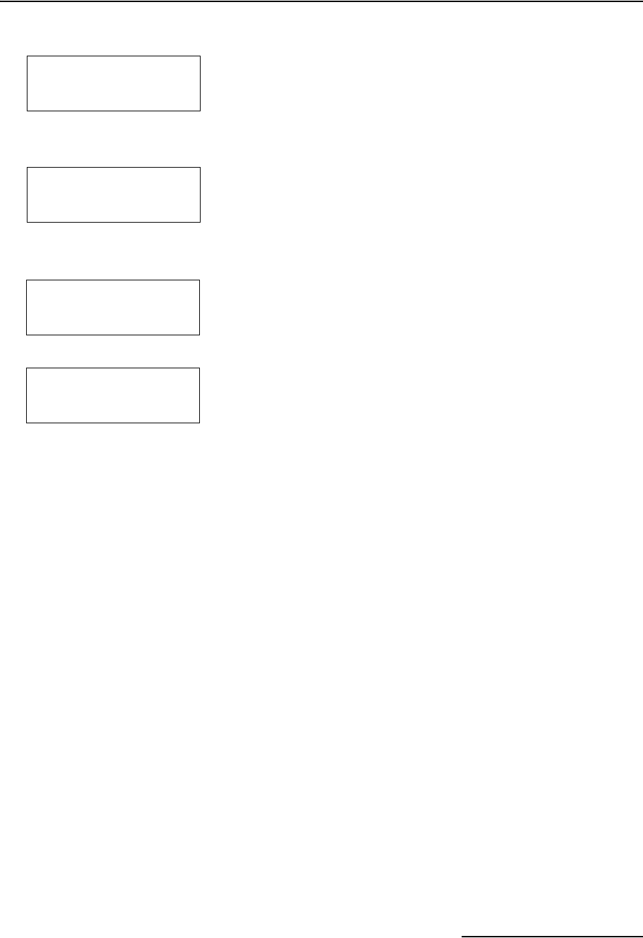
6712FR Refrigerated Sampler
Section 5 Extended Programming
5-17
If the program settings instruct the sampler to take a sample at
the start time, the sampler also draws a sample at the switch
time. When this occurs, the pacing will also be reset at the switch
time.
Time switching is normally used with flow-paced programs that
do not take a sample at start. These programs will place a
sample in the current bottle if it is empty at the switch time, and
then move to the next bottle/set. Pacing intervals are reset at
every switch time.
When you use the time switching feature, the volume in each
bottle or bottle set may vary. Sample volumes that would exceed
the bottle capacity are not taken and a “PROBABLE OVERFILL”
message is logged.
5.10.7 Continuous Sampling Sample programs can be run indefinitely by selecting “YES” at
the “RUN CONTINUOUSLY?” screen. Continuous sampling
resets the distribution when the distribution sequence is com-
plete. That is, when the last bottle/set is reached, the next
bottle/set is the first bottle/set. All pacing modes except
RANDOM are supported.
When running a program continuously, the bottles must be ser-
viced at regular intervals to prevent overfilling the bottles. The
sampler assumes that the next bottle/set is empty and ready to
receive samples. If you are using this feature with two-part pro-
gramming, keep in mind that the parts will most likely reset at
different intervals.
Time Switched
Distribution
1
2 BOTTLES PER
SAMPLE EVENT (1-max)
•Enter the number of bottles
that should receive samples
at each sample event.
2
SWITCH BOTTLES ON:
NUMBER OF SAMPLES
TIME
• Select TIME.
3SWITCH BOTTLES EVERY
__ HOURS, __ MINUTES
• Enter the time between
bottle switches.
4FIRST SWITCH TIME
AT: __:__
• Enter the first bottle
switch time.
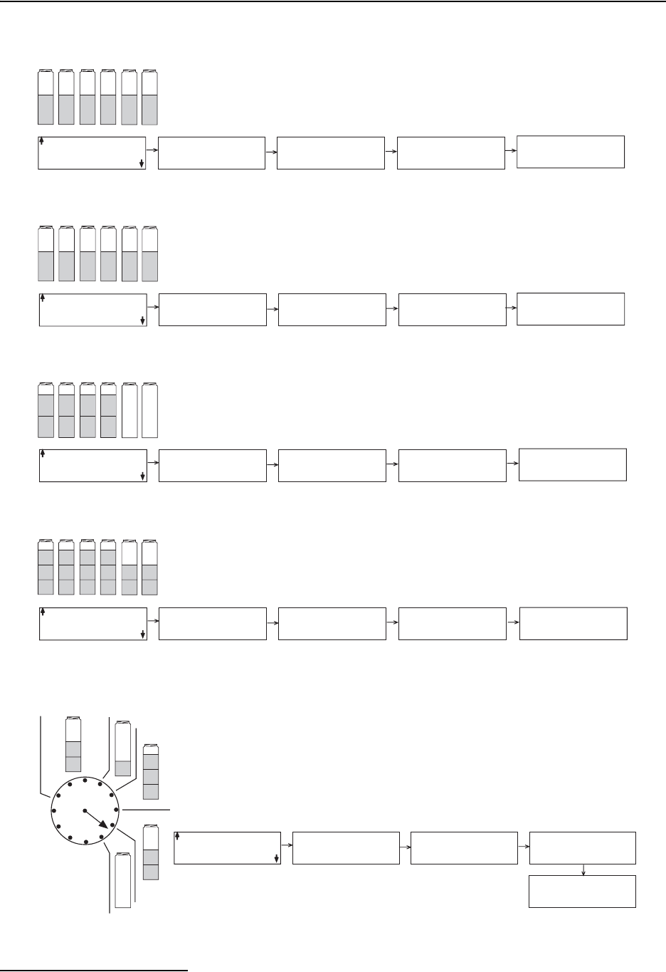
6712FR Refrigerated Sampler
Section 5 Extended Programming
5-18
Figure 5-1 Sample Distribution
Sequential
123456
Bottles-per-Sample
112233
Samples-per-Bottle
1357
2468
Multiple Bottle Compositing
114477
225588
3366
Time Switched (Flow-paced, No sample at start)
1
2
TO
4
5
6
7
8
EXTENDED
PROGRAMMING
ONLY
DISTRIBUTION:
1 BOTTLES/SAMPLE
SWITCH AT 13:00
THEN EVERY 1:00
1 BOTTLES PER
SAMPLE EVENT (1-24)
SWITCH BOTTLES ON:
NUMBER OF SAMPLES
TIME
SWITCH BOTTLES EVERY
1 HOURS, 0 MINUTES
FIRST SWITCH TIME
AT: 13:00
Start Time Time
Override
EXTENDED
PROGRAMMING
DISTRIBUTION:
SEQUENTIAL 1 BOTTLES PER
SAMPLE EVENT (1-24)
SWITCH BOTTLES ON:
NUMBER OF SAMPLES
TIME
SWITCH BOTTLES EVERY
1 SAMPLES (1-50)
YES NO
RUN CONTINUOUSLY?
Each bottle receives one sample from one sample event.
EXTENDED
PROGRAMMING
DISTRIBUTION:
2 BOTTLES/SAMPLE 2 BOTTLES PER
SAMPLES EVENT (1-24)
SWITCH BOTTLES ON:
NUMBER OF SAMPLES
TIME
SWITCH SETS EVERY
1 SAMPLES (1-50)
YES NO
RUN CONTINUOUSLY?
Multiple bottles receive a sample from one sample event.
EXTENDED
PROGRAMMING
Each bottle receives a sample from multiple sample events.
DISTRIBUTION:
2 SAMPLES/BOT TLE 1 BOTTLES PER
SAMPLE EVENT (1-24)
SWITCH BOTTLES ON:
NUMBER OF SAMPLES
TIME
SWITCH BOTTLES EVERY
___ SAMPLES (1-50)
YES NO
RUN CONTINUOUSLY?
EXTENDED
PROGRAMMING
ONLY
DISTRIBUTION:
2 BOTTLES/SAMPLE
3 SAMPLES/BOT TLE
2 BOTTLES PER
SAMPLE EVENT (1-24)
SWITCH BOTTLES ON:
NUMBER OF SAMPLES
TIME
SWITCH BOTTLES EVERY
3 SAMPLES (1-50)
YES NO
RUN CONTINUOUSLY?
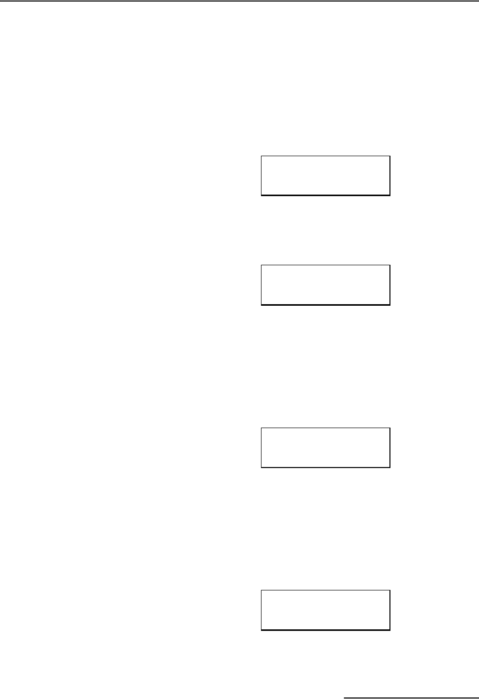
6712FR Refrigerated Sampler
Section 5 Extended Programming
5-19
5.11 Flow Proportional
Sample Volumes
The 6712 can collect flow proportional sample volumes. For some
sampling protocols, these flow-weighted, variable-volume
samples can be more representative of the stream. This is
because stream characteristics often change as the flow fluc-
tuates.
Variable-volume sampling is possible when the sampler is pro-
grammed for Uniform Time pacing. To enable this feature, select
YES at the display asking “DO YOU WANT SAMPLE
VOLUMES DEPENDENT ON FLOW?”
After answering YES, the sampler displays screens to program
the flow proportional volumes. If the sampler has a 700 Series
Flow Module inserted, you will be asked which flow mea-
surement should be used to determine the volumes.
To base the volumes on an external flow measurement device
attached to the Flow Meter connector, select FLOW PULSES. To
base the volumes on the 700 Series Flow Module readings, select
FLOW MODULE VOLUME.
Next, the sampler asks for the SAMPLE VOLUME to collect at
each time interval. This volume is expressed as 10 ml for every X
number of pulses, or if using a flow module, for every volume
unit.
Refer to section 5.11.1, Calculating Variable Sample Volume Set-
tings, for a more detailed discussion on this setting.
The final screen used to program variable-volume sampling is
the MINIMUM SAMPLE VOLUME. If the number of flow pulses
or flow module volume is not sufficient enough to collect this
minimum volume, the sample is skipped and the flow count
carries over to the next sample time. This setting ranges from
10 ml to a maximum determined by the bottle volume.
DO YOU WANT
SAMPLE VOLUMES
DEPENDENT ON FLOW?
YES
NO
FLOW PULSES
FLOW MODULE VOLUME
SAMPLE VOLUME:
10 ml FOR EVERY
___
PULSES
MINIMUM
SAMPLE VOLUME
___
ml
(10 - maximum)
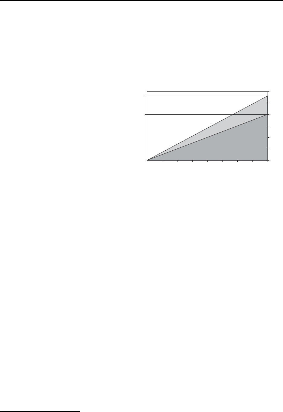
6712FR Refrigerated Sampler
Section 5 Extended Programming
5-20
5.11.1 Calculating Variable
Sample Volume
Settings
The entry for the SAMPLE VOLUME display can be calculated
based on expected flow rates and collection volume requirements.
The number of pulses or flow module volume that you enter
should ensure that the minimum volume of liquid required for
analysis is collected without exceeding the bottle volume capacity
of the sampler. You may find it helpful to determine a range of
values by calculating both possibilities. The number you enter
would be selected from this range. This range is illustrated in
Figure 5-2.
Figure 5-2 Factors Affecting Flow-Weighted Variable-Volume Samples
In other words, at the greatest expected flow, this SAMPLE
VOLUME value should be set to prevent filling the bottle before
the end of the program. An early full-bottle condition would
result in a composite sample that is not representative of the
flow stream.
At the lowest expected flow, the SAMPLE VOLUME value should
be set to ensure that enough sample is collected. If too little
sample liquid is collected, there may not be enough for analysis
although it is a representative composite sample.
For example, consider an NPDES sampling program used to
collect a flow-proportional composite sample for BOD, TSS, and
NH3-N analysis. The laboratory requires at least 1,000 ml for
BOD, 100 ml for TSS, and 400 ml for NH3-N tests. The minimum
composite volume needed for analysis is then 1,500 ml, but to
allow for duplicates and spillage, this volume is doubled to
3,000 ml. The samples are to be collected over an eight hour
period at 15 minute intervals into a 9,400 ml composite bottle.
Flow rates at the site range from 1.5 to 2.0 mgd, the equivalent
volume of 500,000 and 666,667 gallons respectively over the
eight hour period. This flow is measured by an external flow
meter that sends a flow pulse every 100 gallons. Figure 5-3
depicts this scenario.
Total Bottle
Capacity
Minimum
Required Sample
Volume
Time
Flow Volume
Least Expected Flow
Greatest Expected Flow
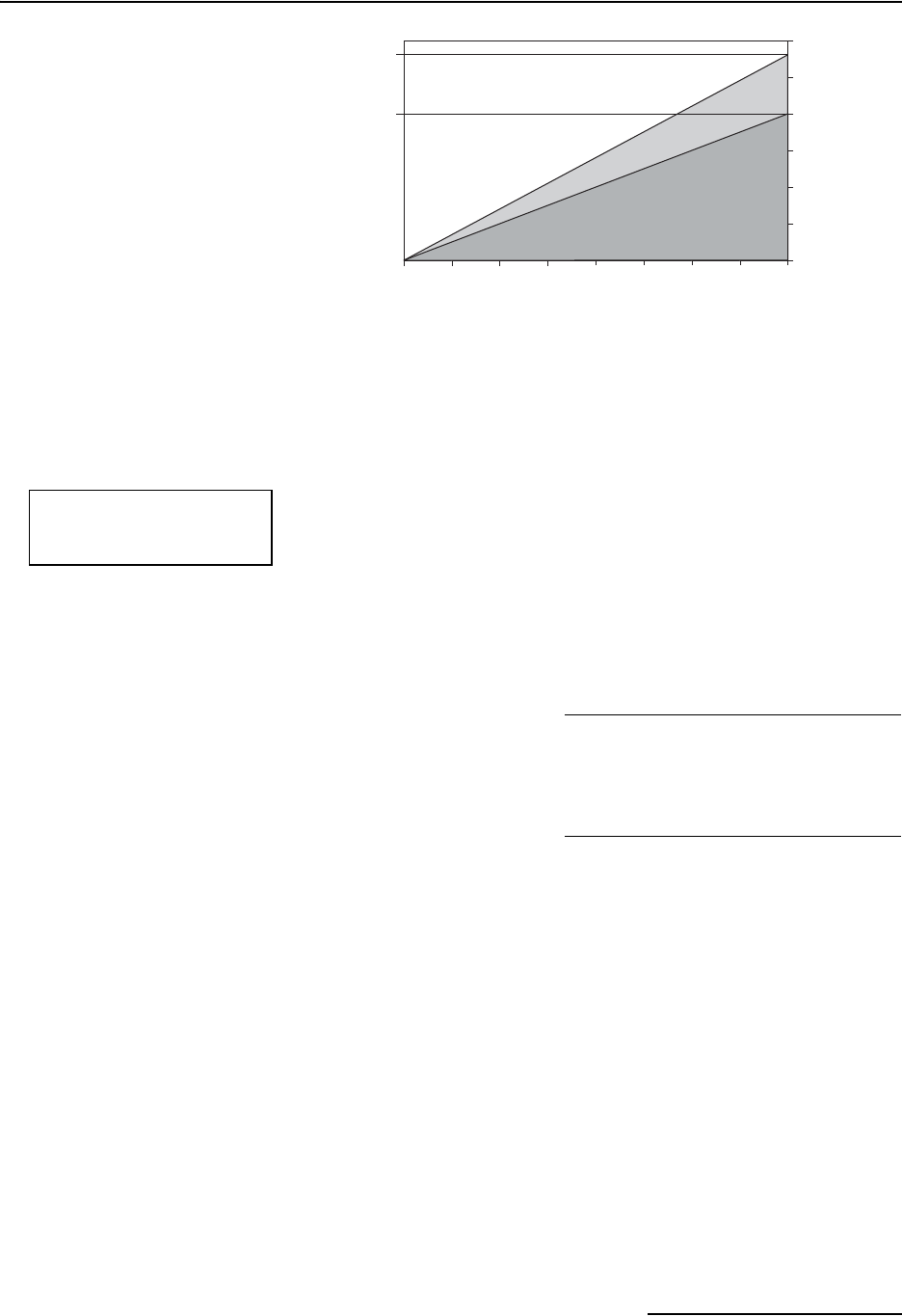
6712FR Refrigerated Sampler
Section 5 Extended Programming
5-21
Figure 5-3 Variable-Volume Scenario
5.11.2 Calculations when
Using an External Flow
Meter
The highest possible SAMPLE VOLUME value is determined by
the minimum volume required for analysis and the least
expected flow rate over the sampling duration. To calculate the
number of pulses at this high end of the range, you should know:
• the least expected flow volume that will pass the flow
measurement point
• the flow volume interval between each flow pulse from
the external flow meter
• the minimum composite sample volume required for
analysis. Allow for duplicates and spillage.
These factors would be applied to the following equation.
From the scenario we can apply the factors for the equation.
Because the SAMPLE VOLUME entry must be in whole
numbers, 16.7 is rounded down to 16. It is important to note that
this number is inversely proportional to the amount of volume
collected. Rounding up would result in less volume collected.
The lowest possible SAMPLE VOLUME value is dependent upon
the highest expected flow and the available bottle volume. To cal-
culate the number of pulses or volume at this low end, you should
know:
• the greatest expected flow volume that will pass the flow
measurement point
• the flow volume interval between each flow pulse from
an external flow meter
• the available bottle volume for sample collection.
9400 ml
Hours
Least Expected Flow
Greatest Expected Flow
3000 ml
012345678
666,667 gal
500,000 gal
SAMPLE VOLUME:
10 ml FOR EVERY
___
PULSES
(Least Total Flow Vol) / (Flow Pulse Vol)
(Minimum Required Vol) / (10 ml per unit)
=
10 ml for every __ pulses
(500,000 gallons) / (100 gallons per pulse)
(3,000 ml / 10 ml)
=
10 ml for every 16.7 pulses
6712FR Refrigerated Sampler
Section 5 Extended Programming
5-22
These factors would be applied to the following equation.
From the scenario we can apply the factors to the equation.
At high flow rates, a number below 7 would overfill the bottle. At
low flow rates, a number greater than 16 would collect too little
sample. Therefore, a value should be selected between 7 and 16
pulses.
5.11.3 Calculations when
Using a 700 Series Flow
Module
The same principles discussed in Section 5.11.2 apply. However,
the equations differ slightly because the flow module directly
measures the stream’s flow volumes. The equation for the high
end of the range is:
Using the same scenario the calculations would be:
The equation for the low end of the range is:
The scenario would be applied as:
Therefore, a value should be selected between 709 and 1667
gallons for the given scenario.
5.12 Sampler Enable Certain external instruments can enable (start) or disable (stop)
a sampler by sending a signal to pin F of the sampler’s flow
meter connector. Isco flow meters, flow loggers, and the Isco 1640
Liquid Level Actuator have a programmable sampler-enable
feature that lets them enable or disable the sampler. You can
define the condition (such as level, flow rate, pH, temperature,
percent, rainfall, and I/O) or combination of conditions that need
to be true in order to enable the sampler. Refer to Figure A-12 in
Appendix A for details on programming sampler enables.
(Greatest Total Flow Vol) / (Flow Pulse Vol)
(Total Bottle Vol) / (10 ml per unit)
=
10 ml for every __ pulses
(666,667 gallons / 100 gallons)
(9,400 ml / 10 ml)
=
10 ml for every 7.0 pulses
(Least Total Flow Vol)
(Minimum Required Vol) / (10 ml per unit)
=
10 ml for every __ units
SAMPLE VOLUME:
10 ml FOR EVERY
___
Gallons
500,000 gallons
(3,000 ml) / (10 ml per gallon)
=
10 ml for every 1667 gallons
(Greatest Total Flow Vol)
(Total Bottle Vol) / (10 ml per unit)
=
10 ml for every __ units
666,667 gallons
(9400 ml) / (10 ml per unit)
=
10 ml for every 709 gallons
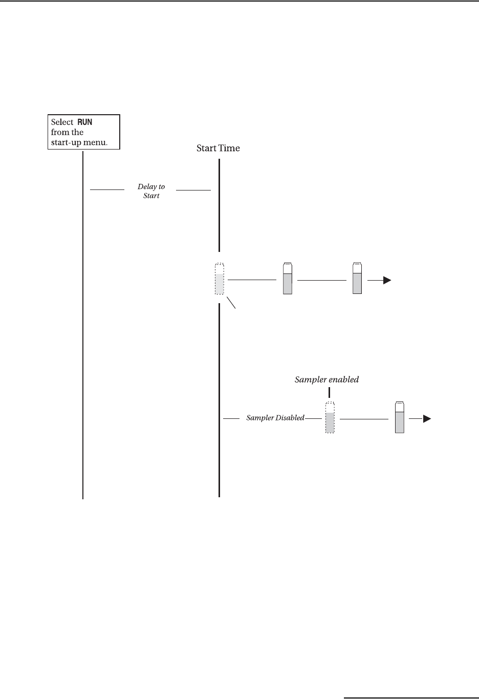
6712FR Refrigerated Sampler
Section 5 Extended Programming
5-23
When the sampler detects that it is disabled at start time, it sus-
pends the program until it is enabled. Once enabled, the sampler
collects a sample only when programmed to take a sample at the
enable time. The diagram in Figure 5-4 shows the sampler’s
response when enabled or disabled at the start time.
Figure 5-4 Start Time Diagram for Sampler Enable Settings
Sampler disabled at
start time by
signal from pin F
A sample event at enable time occurs
only when the program requires a
sample at enable.
Sampler enabled at
start time
A sample event at the start time
always occurs for time-paced programs
(except for random). For flow-paced
programs, it occurs when the program
requires a sample at start time.
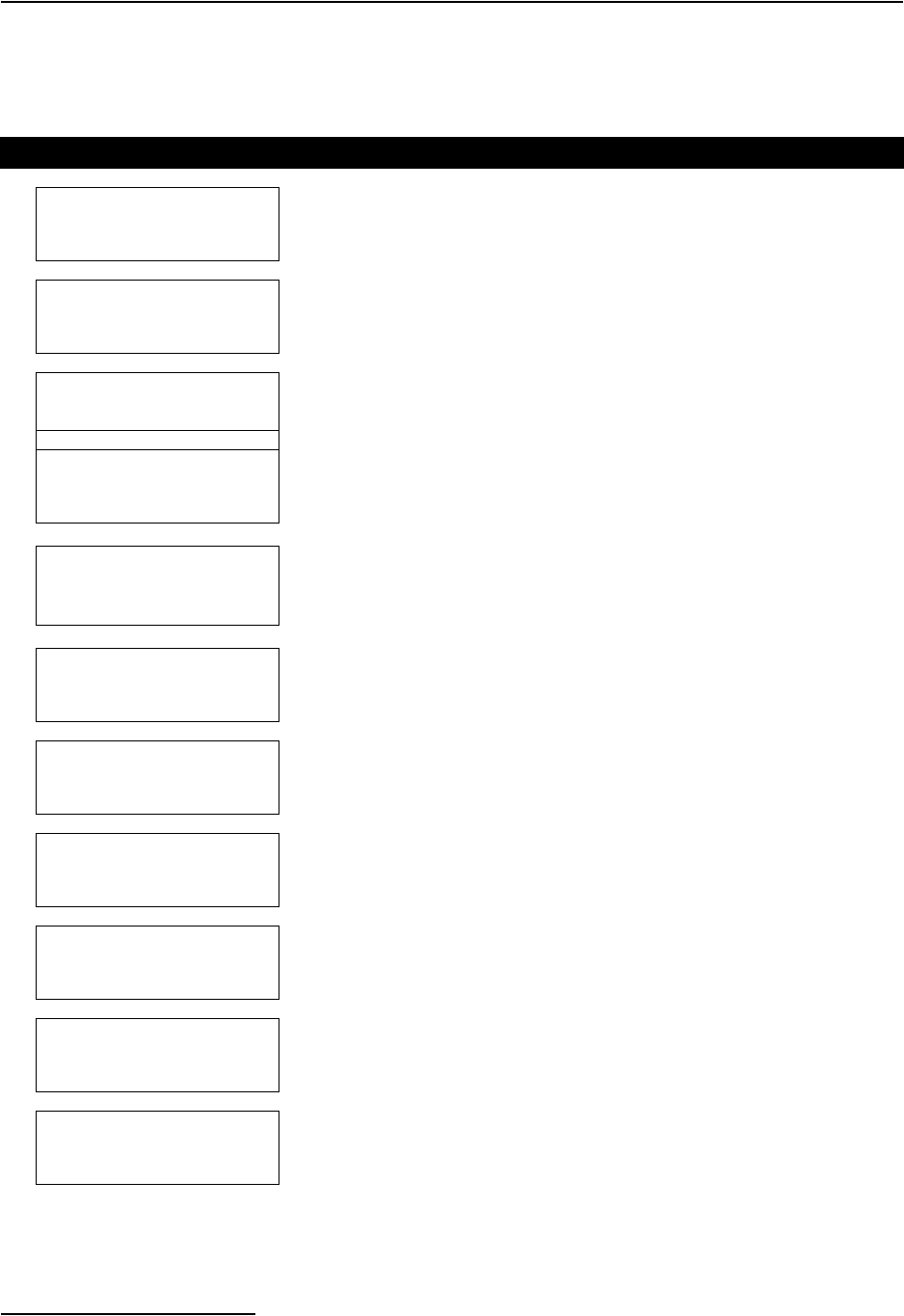
6712FR Refrigerated Sampler
Section 5 Extended Programming
5-24
5.12.1 Sampler Enable This example uses a sampler with an attached 730 Bubbler Flow
Module, Rain Gauge and an SDI-12 sonde at address 5 with four param-
eters.
Table 5-4 Sampler Enable
1
ENABLE:
NONE PROGRAMMED
In this example, you will be enabling the sampler if it rains .5” in 2 hours
and the level goes above 1 foot.
2
ENABLE:
RAIN LEVEL FLOW
TEMP5 pH5 SP_CO5
DO5 NONE
Select RAIN.
3
ENABLE: RAIN
AND OR DONE
Choose AND.
4
ENABLE: RAIN AND
LEVEL FLOW TEMP5
pH5 SP_CO5
DO5 DONE
Select LEVEL.
5
“RAIN” SET POINT:
.5 INCHES PER
__HOURS, __MINUTES
Enter .5 for the inches of rain. Press ↵
.
Enter 2 HOURS.
6
ENABLED WHEN:
ABOVE SET POINT
BELOW SET POINT
Select ABOVE SET POINT.
7RESET RAIN HISTORY?
YES NO
Select YES.
8
“LEVEL” CONDITION
SET POINT
RANGE
RATE OF CHANGE
Select SET POINT.
9
“LEVEL” SET POINT:
+1 ft
( 0.001 - 30.00)
Enter 1 foot.
10
ENABLED WHEN:
ABOVE SET POINT
BELOW SET POINT
Select ABOVE SET POINT.
11
ENABLE:
RAIN >0.50” / 2:00
AND
LEVEL >1.000 ft
Your enable conditions will be summarized on the display.
If correct, press ↵ to continue.
If necessary, make changes to the enable conditions.
6712FR Refrigerated Sampler
Section 5 Extended Programming
5-25
5.13 Sampler Enable
Responses
In addition to programming enable conditions, extended pro-
gramming lets you control the sampler’s response to its enable
state. You can:
• Stay enabled after the first enable.
• Set up a repeatable enable.
• Take a sample at enable or disable.
• Delay the start of sampling after the enable.
• Reset the sampling interval countdown each time the
sampler is enabled.
• Control the sampling interval countdown while
disabled.
• Enable Part B of a two-part program when Part A is
done.
5.13.1 Once Enabled Stay
Enabled
For certain monitoring programs, you may want the sampler to
continue to sample, even though the conditions that enabled the
sampler no longer exist. When you use the ONCE ENABLED,
STAY ENABLED feature, after becoming enabled the sampler
takes samples until it reaches the end of its program.
Note
The STAY ENABLED feature works only when the sampler
becomes enabled following program start. If you need this fea-
ture with enable prior to program start, contact Teledyne Isco
for details.
5.13.2 Repeatable Enable After enabling the sampler, the enabling instrument (or instru-
ments) continues to monitor the conditions and disables the
sampler when the conditions are no longer satisfied. If
re-enabled, the sampler resumes the sampling program.
Note
Repeatable enable is called “sampler latching” in flow meters,
flow loggers, and FLOWLINK. Latching a sampler produces
the same results as selecting YES; the difference is that the
external instrument controls the latching.
5.13.3 Sample at Enable or
Disable
You have the option of directing the sampler to take a sample as
soon as it receives the enable and/or disable signal. If you
program the sampler to stay enabled and choose to take a sample
at enable, the sample interval will be reset at the enable time.
Samples at disable do not affect the sample intervals. Standard
programs do not take a sample at the enable time.
ONCE ENABLED,
STAY ENABLED?
YES NO
SAMPLE AT ENABLE?
YES NO

6712FR Refrigerated Sampler
Section 5 Extended Programming
5-26
5.13.4 Delay To Start Of
Sampling
If you have selected ONCE ENABLED STAY ENABLED and
have chosen to not sample at the enable, you have the oppor-
tunity to suspend the start of sampling. This choice is useful for
storm programs that require a flow-paced sample taken after the
initial grab sample.
5.13.5 “Dry Period” Option For samplers used with a 0.01 inch tip rain gauge, you can cause
the sampler to wait for a “dry” period of under 0.10 inches of rain
over a 72-hour period before running the program. At RUN time,
the sampler asks if you want to restart the 72-hour period. Select
this choice if you want the sampler to disregard any “dry” period
that took place prior to the program start. The sampler will wait
for up to one year for the “dry” period to occur.
5.13.6 Resetting the Sample
Interval at Enable
You may want the pacing countdown to start over each time the
sampler becomes enabled. To accomplish this, select “YES” when
asked if you want to reset the sample interval at enable. The next
sample event will occur at the end of a full interval. Fur-
thermore, if the sampler is enabled several times during the
program, it resets the countdown each time.
Use the reset-interval feature carefully. For example, avoid
resetting the interval when you sample with uniform-time
pacing and want to take samples at specific times.
The effects of resetting the interval can be seen in this example:
A sampler has been programmed to sample every 15 minutes and
to reset the interval when enabled. It receives an enable signal at
10:03 and takes a sample. After resetting the interval, the
sampler takes subsequent samples at 10:18 (not 10:15), 10:33
(not 10:30), and so on.
If you select “NO” when asked if you want to reset the sample
interval at enable, you will be asked if you want to continue the
countdown while disabled. You can have the sampler continue
the countdown, repeating it as often as necessary while the
sampler is disabled, or you may suspend the countdown while
disabled, resuming the countdown as the sampler is enabled. The
standard program allows the countdown to continue while dis-
abled.
START SAMPLING
AFTER A
___ MINUTE DELAY
(1-999)
START “EXTENDED 1”
AFTER A 72 HOUR
“DRY” PERIOD?
YES NO
RESET SAMPLE
INTERVAL AT ENABLE?
YES NO
If you answer “NO” to the above
screen, you will see:
CONTINUE COUNTDOWN
WHILE DISABLED?
YES NO

6712FR Refrigerated Sampler
Section 5 Extended Programming
5-27
5.14 Pauses/Resumes
Pause and resume settings, available in extended programming,
create an intermittent sampling schedule. A program with
pauses and resumes begins sampling at its programmed start
time, continuing until the first pause time and day of the week. It
then suspends sampling until the first resume time, when it
begins sampling again. If the start time falls within a pause
period, the sampler will not begin sampling until the next
resume time. Pauses and resumes repeat weekly.
You can enter up to nine pairs of pause and resume times. The
pause and resume times shown as examples to the left suspend
the program between 5:00 p.m. Monday and 8:00 a.m. on
Tuesday and between 5:00 p.m. Tuesday and 8:00 a.m. on
Wednesday. If the start time is Monday at 8:00 a.m., the sampler
takes samples between 8:00 a.m. and 5:00 p.m. Monday; between
8:00 a.m. and 5:00 p.m. Tuesday; and, continues after 8:00 a.m.
Wednesday. To remove pause and resume settings from a
program, select CLEAR.
A sampler running a pause/resume program resets the pacing
interval at each resume time. You can program the sampler to
take a sample at resume times (see screen at left).
5.15 Running Programs To run an extended program, select run from the main menu.
You may also select YES at the RUN THIS PROGRAM NOW?
screen at the end of the programming screens.
Extended programs scheduled to start at a clock time will not
start until the programmed clock time on or after the first valid
date.
Note that if you have recently calibrated a parameter probe, the
sampler may delay the start and display “PLEASE WAIT” until
valid readings are expected from the probe. The delay accounts
for the time typically required to install the probe, and lasts for
five minutes after you complete the calibration.
5.15.1 Run Time Screens Run time screens, which report the program’s status while
running a program, are explained in Section 4.
5.15.2 Interrupting a
Running Program
Interrupting a running program is also explained in Section 4.
The scrolling menu that appears during the manual paused state
can have two extra options when using extended programming:
Adjust Enable – This option is available for extended sampling
programs that have programmed enable conditions. Selecting
this option allows you to change the set-points or ranges for the
enable conditions. The sampler displays all of the programming
screens that define the thresholds of the programmed enables.
You cannot change the type of enables used or the way they are
combined.
If rain is an enabling condition, you also have the option of
resetting the rain history.
Pause and Resume Screens
Flowcharts containing the pause and
resume screen appear in Appendix
A.
PAUSE RESUME
1. 17:00 MO 08:00 TU
2. 17:00 TU 08:00 WE
CLEAR DONE
SAMPLE AT RESUME?
YES NO
6712FR Refrigerated Sampler
Section 5 Extended Programming
5-28
Adjust Suction Head – If you have chosen to manually enter
the suction head, and are in the manual paused state, the
scrolling menu will have an option to adjust the suction head. If
you make changes to the suction head value, the sampler logs a
changed suction head event.
5.16 Sampling Reports The 6712FR records a variety of data while running a sampling
program. Sample reports can be found in Section 4.
Section 4, Table 4-3 contains a list of source codes and program
events that may be recorded when using either standard or
extended programming.
5.17 Other Functions
In extended programming, the “Other Functions” menu screen
includes options for:
• Maintenance (see Section 7)
• Manual Functions (see Section 4)
• Software Options.
• Hardware
5.18 Software Options The software option screens allow you to set up a number of dif-
ferent software options:
5.18.1 Liquid Detector
Enable/Disable
Under some conditions (pressurized lines, sampling foam), a
more repeatable sample volume may be delivered by disabling
the liquid detector. Selecting NO will turn the Liquid Detector
off.
If the Liquid Detector is off:
• you must enter the SUCTION HEAD
• no RINSES or RETRIES will be available
• you will not be able to CALIBRATE SAMPLE volumes
• the RESULTS report will read a COUNT TO LIQUID of
0
• A complete purge will occur between samples when
using multiple bottles-per-sample distribution.
Other Functions Menu
RUN “PROGRAM NAME”
PROGRAM
VIEW REPORT
OTHER FUNCTIONS
• Select OTHER FUNCTIONS.
MAINTENANCE
MANUAL FUNCTIONS
SOFTWARE OPTIONS
HARDWARE
• Liquid Detector Enable • Display Backlighting
• Normal/Quick View Screens • Event Marks
• Measurement Interval • Pump Purge Counts
• Dual Sampler Mode • Serial Output
• Full Bottle Detection • Remote Access
• Interrogator Connect Power
USE LIQUID DETECTOR?
YES NO

6712FR Refrigerated Sampler
Section 5 Extended Programming
5-29
5.18.2 Programming Style The sampler has two different styles of programming screens:
normal and quick view. These are both explained in Section 3.
When you are in extended programming, the default style is
Quick View, which allows you to move more quickly through the
screens.
If you prefer a step-by-step display for the screens, switch to the
Normal setting.
5.18.3 Measurement Interval
If using a 700 Series module or SDI-12 Sonde parameter for
enabling, the sampler will request a Measurement Interval. The
Measurement Interval allows the sampler to compare the
parameter to the enabling conditions at a rate faster than the
Data Storage interval. If the Measurement Interval is equal to or
greater than the Data Storage interval, the parameter will be
checked at the rate of Data Storage interval.
Normally, there are two considerations when selecting the Mea-
surement Interval: power consumption and duration of the
enabling event. This setting for battery powered samplers will
require some degree of balance between the need to conserve
power yet detect the enabling event before it has passed.
5.18.4 Dual Sampler Mode
Dual Sampler Mode lets you operate two samplers as a pair. The
primary sampler disables the secondary one until the primary
sampler completes its sampling program. The samplers then
reverse roles with the second sampler becoming the primary one.
Setting Up Dual Samplers –
1. Turn on the dual sampler mode in both samplers.
2. Install the samplers.
3. Connect the samplers with the Dual Sampler Mode Inter-
connect Cable by attaching the cable to the sampler’s
flow-meter connectors. If your installation includes a flow
meter or flow logger, use the Dual Sampler Mode to Flow
Meter Cable instead.
4. Decide which sampler is to be the primary sampler; the
primary sampler should be the sampler with the program
you want to run first.
5. Turn the primary sampler on and run its sampling pro-
gram by selecting RUN. After at least 5 seconds, turn the
secondary sampler on and select RUN from its main menu.
How Does It Work? – The primary sampler sends a disable
signal out its flow meter connector. The secondary sampler
receiving the signal is held disabled until the primary sampler
completes its program.
When using a flow meter or flow logger a Dual Sampler Mode to
Flow Meter cable must be used. This cable is constructed so that
the pacing instrument receives only the event marks. Therefore,
a connected flow meter will not receive a bottle number signal,
nor will it be able to control the sampler inhibit.
MEASUREMENT INTERVAL
5 15 30 SECONDS
1 2 5 MINUTES
STORAGE INTERVAL
Dual Sampler Mode
DUAL SAMPLER MODE?
YES NO
• Select YES to put the sampler
in the dual sampler mode.
When you no longer need
dual samplers, return to this
screen to turn the feature off.

6712FR Refrigerated Sampler
Section 5 Extended Programming
5-30
Bottle Full Detection – The sampler can detect a full bottle
condition when collecting samples in a single bottle (composite
sampling). When the sampler detects a full bottle, it stops the
sampling routine.
A BOTTLE FULL condition will also stop a sampling routine
that is set to RUN CONTINUOUSLY.
The Bottle Full Detect screen allows you to enable or disable this
feature. Selecting “YES” enables the sampler to detect a full
bottle and stop the sampling routine. Selecting “NO” disables
this feature. The Bottle Full Detect setting is part of the sam-
pling program. Because it is a program setting, full bottle
detection can be enabled or disabled for each of the four extended
programs. If the Bottle Full Detect setting is critical to your sam-
pling program, always check this Software setting after you
select a different Extended Program.
This feature relies on a post-purge after each sample. When
using the Bottle Full Detect, make sure that post-sample purges
greater than 100 are used.
Bottle Full Detect is always disabled in the Standard Pro-
gramming mode.
Display Backlighting – The display has a backlight that is
adjustable so that the backlight is always off, timed or always on.
In the timed backlight mode the sampler turns the backlight off
after detecting no key strokes within 60 seconds. Any keystroke
(except ON-OFF) turns the backlighting on again. In this mode
the backlight must be on before the sampler accepts a menu
choice or number entry. If you press a key and a screen does not
respond, it is because the keystroke turned the backlight on.
It is recommended that you use either BACKLIGHT ALWAYS
OFF or TIMED BACKLIGHT when using a battery.
Event Marks – The sampler generates an event mark at each
sample event, sending it through the flow meter connector to a
connected instrument. The event mark may also control an
external device; a connected solenoid relay, for example. When
using the event mark for a data logger or to control external
devices, you may need to adjust the mark by changing the factory
settings.
The event mark is adjustable through the software setup screens.
You can set up the sampler to generate an event mark for
EVERY SAMPLE or for COMPLETE SAMPLES.
If you select COMPLETE SAMPLES, the sampler sends a
three-second pulse only after it successfully collects a sample.
The sampler will not send an event mark if an error occurs, such
as “No Liquid Detected.”
If you select EVERY SAMPLE, the sampler will send an event
mark every time a sample is initiated. The event mark signal can
be a:
• 3-second pulse at the beginning of the pre-sample purge.
Bottle Full Detect
BOTTLE FULL DETECT?
YES NO
Adjusting the Display
Backlighting
BACKLIGHT ALWAYS OFF
TIMED BACKLIGHT
CONTINUOUS BACKLIGHT
Event Marks
EVENT MARK SENT FOR:
EVERY SAMPLE
COMPLETE SAMPLES
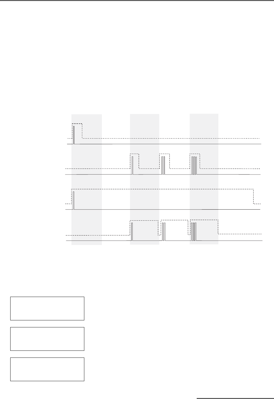
6712FR Refrigerated Sampler
Section 5 Extended Programming
5-31
• 3-second pulse at the beginning of forward pumping
only, marking the time the sampler deposited the
sample.
• Variable duration pulse generated during the pump
cycle, from the beginning of the pre-sample purge to the
end of the postsample purge.
• Variable duration pulse generated only during forward
pumping.
Figure 5-5 shows event mark timing diagrams.
Bottle Number – Concurrent with the event mark, the sampler
also sends a bottle number signal. The bottle number signal is a
series of pulses. The number of pulses sent represents the bottle
currently accepting a sample (see Figure 5-5).
Figure 5-5 Event Mark Timing Diagram
5.18.5 Pre-sample and
Post-sample Purge
Counts
The pre-sample purge is when the pump runs in reverse clearing
the strainer of any debris before taking a sample. The pre-sample
purge is set at 200 pump counts. After the sample is taken a
post-sample purge occurs to clear the liquid from the suction line.
The duration of the post-sample purge is determined by the
length of the suction line to maximize the battery life. The pre-
and post-sample purge can also be manually set.
This diagram shows the pulses sent for a bottles-per-sample distribution scheme
Presample Purge Rinse Cycle Pump Volume 1 Pump Volume 2 Pump Volume 3 Postsample Purge
Event Mark
Event Mark
Bottle Number
Event Mark
Bottle Number
Bottle Number
Pulse at Beginning of
Presample Purge
Pulse at Beginning of
Forward Pumping
Variable Duration Pulse
During Entire Pump
Event Mark
Bottle Number
Variable Duration Pulse
During Forward
Pumping
PRE-SAMPLE PURGE:
____COUNTS
(10-9999)
POST-SAMPLE PURGE:
DEPENDENT ON HEAD
FIXED COUNT
POST-SAMPLE PURGE:
____COUNTS
(10-9999)
6712FR Refrigerated Sampler
Section 5 Extended Programming
5-32
5.18.6 Serial Output
Serial ASCII data can be output through the controller’s interro-
gator port. The output frequency is user-selectable: every 15
seconds, every minute, every 5 minutes, every 15 minutes, or by
command.
To receive serial data as a periodic output:
1. Select YES at screen asking if you want periodic serial out-
put.
2. Select the appropriate baud rate setting in screen . Note
that at all baud rates the data is sent with no parity, eight
data bits, and one stop bit. If you have difficulty with the
connection, try a slower baud rate.
3. Select the desired output interval in screen.
4. Connect to the 6712 controller’s interrogator connector
using a standard interrogator cable.
To receive serial data by command:
1. Select NO at the screen asking for periodic serial output .
2. Connect your computer to the 6712 controller’s interroga-
tor connector with a standard interrogator cable, P/N
60-2544-040 (25 pin) or 60-2544-044 (9 pin).
3. Configure your communications software for a baud rate
no higher than 19,200 kb, no parity, 8 data bits, and 1 stop
bit.
4. From the computer’s keyboard, type “?” repeatedly until
the 6712 controller determines the baud rate. Once the
baud rate is known, the 6712 returns an identification ban-
ner. This banner indicates that the connection is working
properly.
5. Type DATA<CR> each time the data string is desired.
The serial data is in comma-separated-value format. Only the
values that the sampler is set up to measure will be output in the
data string. The string is terminated with a <CR><LF>. To read
the data in the string, refer to Table 5-5. This serial data can also
be accessed from a remote location using the optional dial-out
modem (see Section 7).
Note
The internal modem is disabled when an interrogator cable is
connected to the sampler’s Interrogator port. It cannot receive
incoming calls, and the alarm dialout is rendered inoperative,
while this cable is connected. Disconnect the interrogator
cable in order to use the 4200T modem.
Programming the serial
output
PERIODIC
SERIAL OUTPUT?
YES NO
PORT SETTINGS:
9600N81 4800N81
2400N81 1200N81
SERIAL OUTPUT EVERY:
15 SEC 1 MIN
5 MIN 15 MIN

6712FR Refrigerated Sampler
Section 5 Extended Programming
5-33
Table 5-5 Serial Data Codes
Identifier Parameter Units
B?1Bottle number and time days since 1-Jan 1900
CR Current day’s rain tips (rolls over every 256
tips)
CS2Checksum unsigned long
DE Description 6712 Sampler
FL Flow cubic meters per second
ID Unit specific identifier 10 digit unsigned long
LE Level meters
MO Model 6712
PE Percent percent of full scale
PH pH none
PR Previous day’s rain tips (rolls over every 256
tips)
RA Rain tips (rolls over every 256
tips)
RTE Refrigerator Temperature degrees celsius
SS Sampler enable state logical
TE Temperature degrees celsius
TI Current time days since 1-Jan-1900
VE Velocity meters per second
VO Volume cubic meters
VSI Velocity signal strength percent
VSP Velocity spectrum strength percent
COa3Conductivity milliseimens per centimeter
DOaDissolved oxygen milligrams per liter
PHapH none
SAaSalinity parts per thousand
SPaSpecific Conductance milliseimens per centimeter
TDaTotal Dissolved Solids grams per liter
TEaTemperature degrees Celsius
ORaOxidation reduction potential millivolts
LEaLevel meters
MMaAmmonium-nitrogen milligrams nitrogen per liter
MAaAmmonia-nitrogen milligrams nitrogen per liter
NIaNitrate-Nitrogen milligrams nitrogen per liter
TBaTurbidity nephelometric turbidity units

6712FR Refrigerated Sampler
Section 5 Extended Programming
5-34
5.18.7 Program Lock The specialized software option Program Lock (P/N 60-9003-532)
may be purchased from Teledyne Isco.
Once activated, the purchased option is always available, even if
the software is upgraded at a later time. The option must be
installed at the factory. Consult the factory for further
details.
To view which software options have been activated, select VIEW
REPORT>SYSTEM IDs. A software options screen will list a
code for each active option. The code for Program Lock is 1108.
The Program Lock adds password security to the 6712 sampling
programs. With this option activated, a user-selected password
(up to five digits) must be entered before any program changes or
run time modifications can be made. Run time modifications
include accessing the Manual Pause menu options and shutting
off the sampler. You will still be able to run the current program,
view reports, and interrogate the sampler without the knowledge
of the password.
If three consecutive attempts to enter the password fail, a five
minute “time-out” will follow in which most keys are deactivated.
The user-selected password defaults to “6712” and may be
changed in the Software options that are available in the
Extended Program mode (see example at left). While the
password may only be changed in the Extended Program mode,
the program lock works for both Standard and Extended pro-
grams.
Should you forget your password, a key code can be obtained
from Teledyne Isco’s Customer Support department for a
nominal fee.
CLaChloride milligrams per liter
CPaChlorophyll micrograms per liter
FLaFlow rate cubic meters per second
VOaFlow volume cubic meters
xxDa4Other data not listed above
• The three most recent samples will have entries as B?. The
“?” will be the first bottle number in the set. If the sample is a
grab sample, it will be shown as B0.
• An “a” in the identifier indicates an SDI-12 address.
•“XX” matches the data label for the SDI-12 parameter.
• The checksum does not include the checksum, carriage
return, and linefeed.
• The string is terminated with <CR><LF>.
Table 5-5 Serial Data Codes (Continued)
Identifier Parameter Units
PROGRAM LOCK DISABLED
ENABLE PROGRAM LOCK?
YES NO
CHANGE PASSWORD TO
----------
REENTER NEW PASSWORD
---------
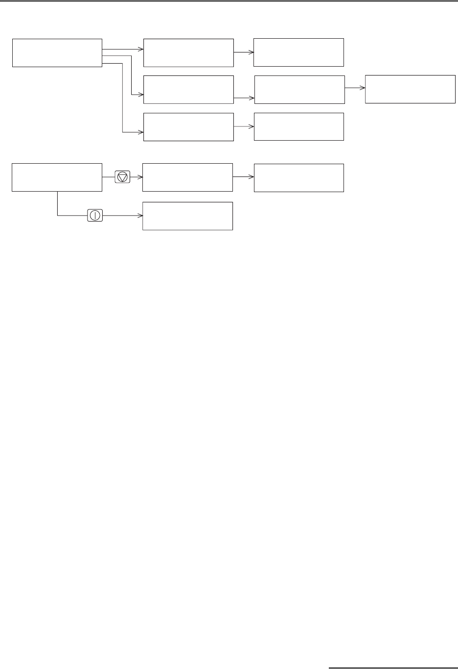
6712FR Refrigerated Sampler
Section 5 Extended Programming
5-35
Figure 5-6 Password Protected Functions
RUN
PROGRAM
VIEW REPORT
OTHER FUNCTIONS
MAINTENANCE
MANUAL FUNCTIONS
PROGRAMMING STYLE
From Standby
While Running a Program
SAMPLINK REPORT
FLOWLINK REPORT
CUSTOM REPORT
ALL REPORTS
Programming
Screens
ENTER PASSWORD:
____
VIEW DATA
SYSTEM IDs
CONFIGURE REPORTS
ENTER PASSWORD:
____
SAMPLE 3
IN 00:03:26 ENTER PASSWORD:
____
STOP PROGRAM
RESUME PROGRAM
VIEW DATA
GRAB SAMPLE
ENTER PASSWORD:
____
Stop Key
ENTER PASSWORD:
____
On/Off Ke
y
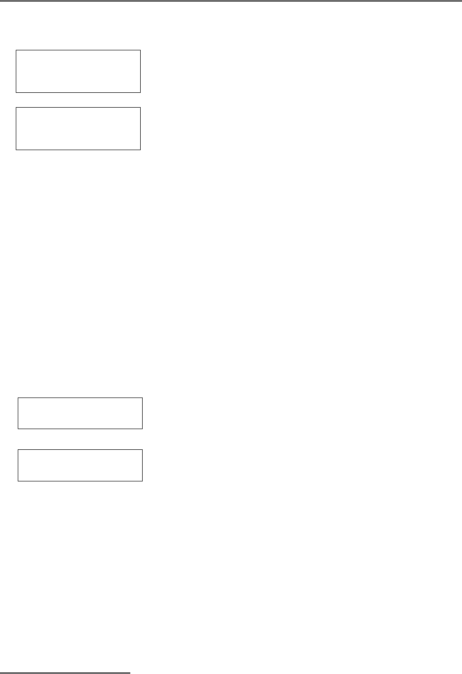
6712FR Refrigerated Sampler
Section 5 Extended Programming
5-36
5.19 Hardware Setup
The hardware setup screens make adjustments to the sampler’s
hardware-based features:
5.19.1 SDI-12 Sonde Setup The 6712 supports SDI-12 sondes. For more information on
setting up sondes, refer to Section 6.
5.19.2 Rain Gauge Setup With standard programming, the sampler does not record rain
gauge readings. However, with extended programming, recording
the rain gauge readings and the rain enable option can be turned
on or off. Enter the hardware setup and follow the screens to the
left in the margin.
When asked if you have a rain gauge connected, select YES to
record the rain gauge readings and add RAIN as a sampler
enable option. Select the appropriate tip for the rain gauge. The
sampler will then create a rain memory partition and update the
available sampler enable conditions.
Select NO to disable the readings and the sampler enable option.
When you select NO, the sampler removes the rain memory par-
tition, leaving the memory space available for other reading
types.
RUN “PROGRAM NAME”
PROGRAM
VIEW REPORT
OTHER FUNCTIONS
• Select Other Functions
MAINTENANCE
MANUAL FUNCTIONS
PROGRAMMING STYLE
HARDWARE
• Select Hardware
• SDI-12 Sonde Setup • Pager Numbers
• Rain Gauge Setup •Text Messaging
• I/O Pin Programming •Refrigerator Temperature
•Dialout Alarms •Analog Outputs
DO YOU HAVE A
RAIN GAUGE CONNECTED?
YES NO
• Select YES.
RAIN GAUGE:
0.01 inch TIP
0.1 mm TIP
• The rain gauges are set up to
tip on either .01 inch or .1 mm.
Select the desired tip.

6712FR Refrigerated Sampler
Section 5 Extended Programming
5-37
5.19.3 I/O Pin Programming Pins C, H, and I on the Rain Gauge Connector are user-con-
figured as I/O1, I/O2, and I/O3 (Input/Output pins) respectively.
Each pin can be either an input for sampler enabling, or an
output for alarms.
Note
The state of the I/O lines is not defined when the sampler is
OFF.
The enable input requires a pulse signal of 5 to 15 volts. Teledyne
Isco offers optional interface modules for converting from a 4-20
mA analog or pulse duration signal.
The alarm output can be set for any RUNNING PROGRAM or
RUN ERROR state. In addition, the CONDITIONS output can
report alarm conditions using the parameters the 6712 is con-
figured to measure. You can set thresholds for one or two condi-
tions and the CONDITIONS output can then trigger alarms
when the measured parameters exceed the threshold.
Alarm function requires an alarm interface module,
factory-installed talking modem, or external digital cellular
modem (see Section 5.19.4 Dialout Alarms).
Teledyne Isco offers a module designed to provide one, two, or
three contact closures. The alarm module can interface the
sampler with many types of non-Isco devices. For more infor-
mation about the alarm module, contact your Teledyne Isco sales
representative.
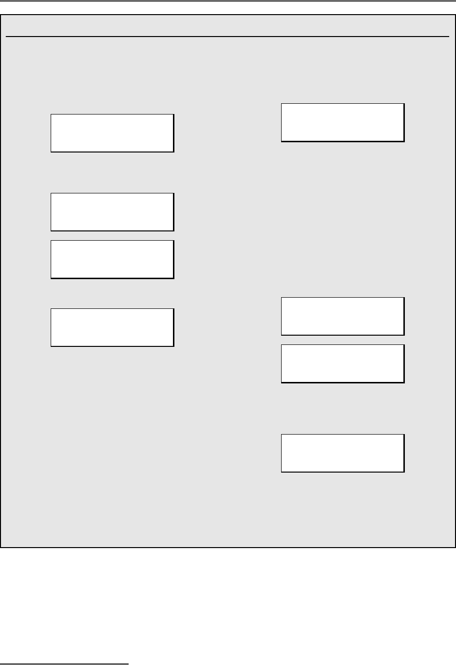
6712FR Refrigerated Sampler
Section 5 Extended Programming
5-38
Example: I/O Pin Programming
Although the screens displayed may vary depending on
your site setup, the programming sequence will be the
same or similar to the following example.
1. Select OTHER FUNCTIONS to enable the dialout
alarm.
2. Select hardware and use the down arrow to scroll
to the I/O screen.
3. Select the first pin to program.
From this screen, your choices are viewed by
scrolling with the arrow buttons:
PGM RUNNING
PGM ENABLED
‘A’ ENABLED
‘B’ ENABLED
PROGRAM DONE
‘A’ DONE
‘B’ DONE
RUN ERROR
FLOW-THRU
CONDITIONS
NONE
I/O ENABLE
Note: All choices listed are alarm output settings,
except for I/O ENABLE. This is the input function to
enable the sampler via an external device.
4. If you select CONDITIONS, the sampler will display:
Depending on what equipment is connected to your
sampler, you may see other parameters in addition to
RAIN, such as LEVEL, FLOW, VELOCITY, etc. Under
CONDITIONS, you can program limits for a condition to
trigger the alarm when the measured parameter
exceeds its limit. You can use one or two conditions to
trigger one alarm, using AND or OR operators.
5. When you select a parameter with the arrow keys
and Enter, you can then program the limits for
alarm triggering. For example, if you select rain,
the sampler will display:
“I/O IS HIGH” means “Alarm is triggered.” Select
ABOVE or BELOW, then select whether or not to reset
rainfall history when the alarm is triggered:
Continue with programming I/O2 and I/O3 in the same
manner, or if additional alarms are not needed, select
NONE.
RUN “EXTENDED 1”
PROGRAM
VIEW REPORT
OTHER FUNCTIONS
MAINTENANCE
MANUAL FUNCTIONS
SOFTWARE OPTIONS
HARDWARE
↑
I/O1 = NONE
I/O2 = NONE
I/O3 = NONE
↓
SET I/O1:
I/O1:
RAIN NONE
"RAIN" SET POINT:
1.00 INCHES PER
1 HOURS, 0 MINUTES
I/O IS HIGH WHEN:
ABOVE SET POINT
BELOW SET POINT
RESET RAIN HISTORY?
YES NO
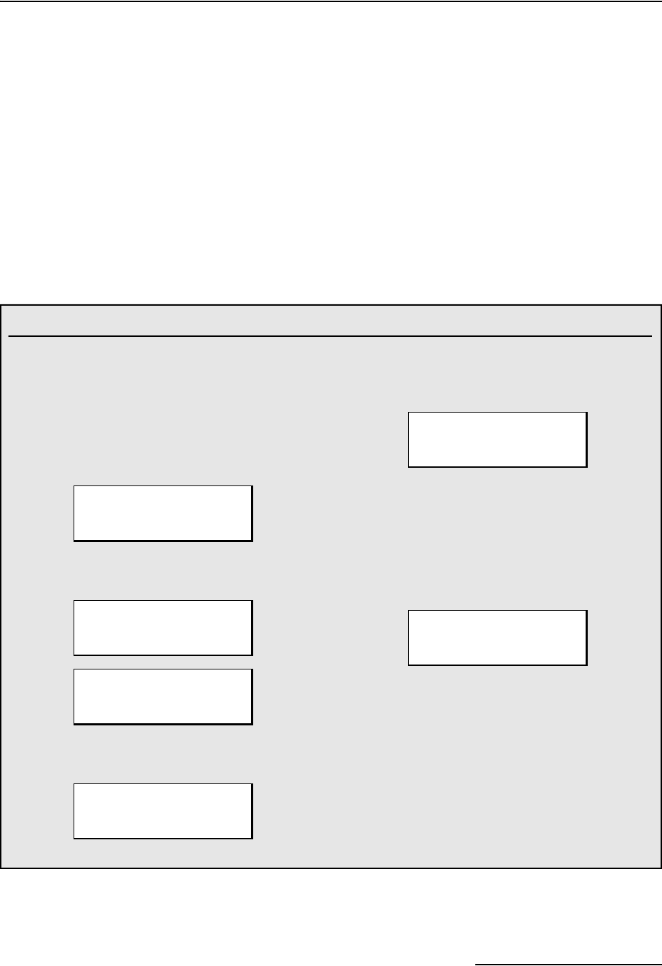
6712FR Refrigerated Sampler
Section 5 Extended Programming
5-39
5.19.4 Dialout Alarms Dialout alarms require the sampler to be equipped with the
factory-installed 2400 baud talking modem, or the external
digital cellular CDMA or GSM modem. The dialout alarm allows
the sampler to notify a contact list when an “alarm” condition
exists (is true).
At the transition to the true state, any programmed I/O output
can cause the sampler to warn of the alarm condition. As many
as three telephone numbers can be entered. The sampler tries
each telephone number in succession until the alarm is acknowl-
edged. For each alarm condition, the sampler will attempt each
telephone number entered a maximum of five times, at user spec-
ified intervals.
Alarms are set up through the I/O programming menu, shown in
Section 5.19.3. “I/O1”, “I/O2”, and “I/O3” represent the three
alarms.
Example: Dialout Alarms
If the controller is equipped with a dialout modem, it
can be programmed to notify a telephone or pager
contact list when an alarm condition is true.
Before proceeding the I/O conditions must be defined.
Refer to section 5.19.4. These steps program a dialout
alarm when the condition defined for I/O1 is true.
1. Select YES to enable the dialout alarm.
The controller asks the same question for IO2 and
IO3. Select NO.
2. Using the number entry keys, enter as many as 3
telephone numbers to the contact list.
If the phone number requires extended characters,
or if you need to designate a number as a pager,
press the decimal key. The controller displays:
Use an arrow key to select a code and press Enter
to insert it in the number on the DIALOUT
NUMBERS screen.
3. Enter the delay time between each attempt. A
delay will allow time between attempts so you can
return a call to the controller to acknowledge the
alarm condition.
Note: Numbers may be removed from the list by
advancing the cursor to the very end of the number
with the right arrow key, then pressing the left arrow key
to erase the number.
DIALOUT WHEN IO1
BECOMES TRUE?
YES
NO
DIALOUT WHEN IO2
BECOMES TRUE?
YES
NO
DIALOUT WHEN IO3
BECOMES TRUE?
YES NO
DIALOUT NUMBERS:
1. 9,55555550001
2. 9,55555550002
3.
P
5550003
SELECT CODE
,#*
PAGER
__ MINUTE
DELAY BETWEEN CALLS
(0-99)
6712FR Refrigerated Sampler
Section 5 Extended Programming
5-40
When the call is answered, the sampler’s modem announces the
alarm condition (analog talking modem) or sends a digital text
message (external cellular modem), and the sampler’s three-digit
ID number. To acknowledge the call, press the (star) key, and
the three-digit ID number on your phone. The sampler will reply
with an acknowledgment when the keyed entry is correct.
A record of alarms and acknowledgements is available in the
Sampling Report. When the sampler detects the alarm condition,
it records the type of alarm and the time it occurred. Acknowl-
edgements are a separate Sampling Report entry, recording the
time and telephone number that responded to the call.
As mentioned previously, as many as three telephone numbers
may be entered. The modem can dial up to 25 digits. Enter
numbers using the numeric keys on the sampler keypad. When
entering telephone numbers longer than 17 digits, the display
will scroll.
Extended characters, the Comma (,), Pound (#), and Star (*), also
may be included in the 25 digits. To enter an extended character,
press the Decimal Point key on the sampler keypad. The sampler
displays a screen used to select and enter the extended char-
acters. Each comma entered will cause the modem to pause for
two seconds before proceeding with the remaining digits.
Phone numbers that are no longer needed can be removed.
Advance the cursor to the end of the telephone number and then
press the Left Arrow key to erase the preceding character. If the
cursor is not at the end of the telephone number, the Left Arrow
key will only shift the cursor without erasing any characters.
Dialout telephone and pager numbers are included in the
Program Settings Report.
Note
Connecting either the serial output or the standard interrogator
cable to the sampler disables the internal dial-out modem. The
interrogator or serial output cable must be disconnected before
you can use the modem.
5.19.5 Pager Numbers The extended character screen contains a pager option that des-
ignates the phone number as a pager. When programmed as a
pager number, an identification string will be sent seven times
after the pager number is dialed, with a three second delay
between strings.
An example identification string would be “828-1”, meaning
“Alarm condition #1 exists at sampler 828”. If more than one
alarm condition exists, the string would read similar to “828-1-3.
5.19.6 Digital Modem Text
Messaging
The sampler can send alarms in the form of text messages con-
taining the same information as that found in voice messages.
To use this option, you must have:
• a cellular phone with text messaging capabilities
*
6712FR Refrigerated Sampler
Section 5 Extended Programming
5-41
• an external digital modem
recommended: Teledyne Isco’s CDMA cellular modem
part # 60-5314-489
or GSM cellular modem part # 60-5314-563
Note
If an internal voice modem is installed, the sampler will use
that modem, and text messaging will be disabled.
When you enter each of the (up to three) phone numbers for the
sampler to call, if text messaging is active, a request for the TAP
(Telocator Alphanumeric Protocol) server number and communi-
cations parameters will be made.
As with voice messaging, the sampler will dial each telephone
number up to five times per alarm condition, until the message is
acknowledged.
5.19.7 Refrigerator
Temperature
Teledyne Isco offers a temperature sensor intended for use with
the 6712FR Refrigerated Sampler. The optional sensor connects
to the Rain Gauge port and uses I/O3 to transmit its temperature
readings to the 6712.
Note
If alarms are being used, the temperature sensor is simply
plugged into the panel mount on the one- or two-alarm output
module. Because the temperature sensor uses I/O3, it cannot
be used with a three-alarm output module.
To configure an attached temperature sensor, select “FR-TEMP”
as the input for I/O3. The 6712 will display the NEW
HARDWARE SETUP screen. Select DONE and the 6712 recon-
figures its memory partitions to record the temperature
readings.
Temperature readings are updated approximately every 2.5
seconds. The readings are stored as FR-TEMP readings at the
data storage interval. You can retrieve a history of temperature
readings through the 6712’s reports. The temperature data also
can be used as a sampler enable condition.
5.19.8 Analog Output Teledyne Isco offers three analog outputs as a factory installed
option. The option is installed inside the controller and includes a
six-pin connector to interface with external devices.
The analog outputs can be programmed for either 0-to-20 mA or
4-to-20 mA operation. With the exception of rain, any parameter
that the 6712 sampler is currently measuring can be used to
control any (or all) of the analog output channels. Programming
the outputs requires parameter levels at each end of the analog
range and then assumes a linear relationship between those
points. MANUAL CONTROL of each output is also available.

6712FR Refrigerated Sampler
Section 5 Extended Programming
5-42
Note
The internal analog output can not be installed in a controller
that has the internal voice modem also installed. Contact the
factory for information regarding external cellular modem
options.
Flowcharts for analog output screens appear in Appendix A.
5.20 Memory The 6712 Sampler contains 512 kilobytes of battery backed RAM
(Random Access Memory) that stores:
• Five sampling programs
• The sampling results from the most recent program
• The rainfall data collected from rain gauges
• The data from a refrigerator temperature sensor
• The data collected from a 700 Series module
• Parameter data collected from an SDI-12 Sonde
• Calculated flow information from the current flow
module
The sampling results memory stores up to approximately 1004
events (the actual number is dependent on the number of SDI-12
parameters). The program run and start time information is
logged as four events. These four entries are held for the duration
of the program. The remaining 1000 are for logging sample
events, program events, and errors from the currently running
program. If the running program exceeds 1000 events, the data
will “roll over.” That is, the sampler will replace the oldest stored
event with the newest event. When using an SDI-12 sonde, the
sampler logs additional entries at each sample event.
Module, sonde, refrigerator temperature, and rain gauge
readings are stored in memory partitions. The storage capacity
depends on the reading types, the number of bytes per reading,
and the data storage interval.
The sampler clears the sampling results memory when the site
description changes. It is important to collect the sampling
results before changing the site description – the data can not be
retrieved afterwards. Keep in mind that the description may
change when selecting an extended program.
The partition data is cleared when the sampler automatically
creates and sizes the memory partitions. This occurs when you:
• Select a new program with a different storage interval
• Change the Data Storage Interval in the current
program
• Change the programming mode
• Install a new 700 Series Module
• Change 700 Series Module mode of operation
• Add or remove a rain gauge with the Hardware Setup

6712FR Refrigerated Sampler
Section 5 Extended Programming
5-43
• Add or remove a refrigerator temperature sensor as I/O3
• Add or remove a SDI-12 sonde parameter with the
Hardware Setup
• Reinitialize the sampler
The stored data is lost as the sampler reformats its memory. As a
precaution, before clearing the memory, the sampler display will
show the following message:
If you want to keep the stored data, download it before pro-
ceeding. When DONE is selected, the sampler clears the stored
data and reformats the memory partitions. The sampler then dis-
plays the new capacity of the partition memory.
If the duration is too short, try changing the data storage
interval or eliminating unnecessary reading types in the
Hardware or Module Setup. For example, a sampler configured
with a 730 Bubbler Module and a rain gauge storing data at a
one-minute interval, creates level and rainfall partitions that
hold 100 days of readings. Changing the storage interval to two
minutes extends the storage capacity to 201 days.
The sampler does not have to be running a program to store
readings. When the sampler is on, it stores readings at the
selected data storage interval. Once the partition is filled, the
readings roll over.
When the sampler is running a program, the partitions become
“triggered” by the programmed start time or the first enable
time, whichever is later. A triggered partition continues to log
readings at the selected interval, but will not replace any
readings taken after the trigger event. The sampler fills the par-
tition and then stops recording to preserve the data. The first
reading preserved in a full partition is one hour before the
trigger event. A full partition can be reset by starting another
program or changing storage parameters.
If you need continuous readings for analysis, be sure to collect
the readings before the partition fills or rolls over to avoid gaps
in the data.
INTERVAL CHANGED --
DOWNLOAD DATA NOW
OR LOSE ALL DATA!
DONE
PARTITION MEMORY
WILL LAST 13 DAYS

6712FR Refrigerated Sampler
Section 5 Extended Programming
5-44
5.21 Pressurized Lines The sampler can obtain samples from pressurized lines, as long
as the line pressure remains below 15 PSI (pounds per square
inch). Pressures greater than 15 PSI may prevent the sampler
from purging the suction line; moreover, extreme pressures can
force liquid past the pump, even when the pump is not running.
For more consistent sample volumes from lines under constant
pressure, calibrate the samples. Teledyne Isco does not rec-
ommend sampling from pressurized lines.
5.22 Command Driven
Operation
The 6712 controller can be used as a slave to an external con-
troller. The external controller is responsible for determining
when to take a sample, how much volume to pump, and where to
put the sample. The external controller directly interfaces to the
sampler via an RS-232 communications port at 2,400-19,200
baud, 8 data bits, no parity, and 1 stop bit. A comma-sepa-
rated-value protocol is used by the external controller to make
requests, and by the sampler to report results. Use a standard
computer connect cable (see Appendix E) to connect the sampler’s
interrogator port and the external controller.
For information on serial data codes and their meanings, refer to
Table 5-5 Serial Data Codes in this section.
The 6712 Sampler will respond to three commands: Turn
Sampler On, GET STATUS, and TAKE SAMPLE. All commands
must include the instruction set. The checksum value is optional.
The available commands are:
1. Turn Sampler On: STS,2,CS,582<CR>
• “582” is the byte-by-byte sum of the ASCII values in the
string “STS, 1,CS”.
• “<CR>” is a carriage return signifying the end of the
command.
• If the sampler is OFF, this command will turn it ON
before returning status info.
2. Get Status: STS,1,CS,581<CR>
“STS,1” instructs the sampler to return the current status.
• “CS,581” is the optional checksum value. The
byte-by-byte sum of the ASCII values in the string
“STS,1,CS” is 581.
• “<CR>” is a carriage return signifying the end of the
command.
3. Take Sample: BTL,2,SVO,100,CS,1039<CR>
The TAKE SAMPLE command is only valid if the sampler is
WAITING TO SAMPLE.
• “BTL,2” instructs the sampler to place the sample in
bottle 2.
• “SVO,100” instructs the sampler to take a 100 ml
sample.

6712FR Refrigerated Sampler
Section 5 Extended Programming
5-45
• “CS,1039” is the optional checksum value. The
byte-by-byte sum of the ASCII values in the string
“BTL,2,SVO,100,CS,” is 1039.
• “<CR>” is a carriage return signifying the end of the
command.
5.23 Command Driven
Sampler Responses
The 6712 Sampler’s response string is the same for each of the
three commands. A sample response string is shown below:
MO,6712,ID,2424741493,TI,35523.50000,STS,1,STI,35523.4187
5,BTL,2,SVO,100,SOR,0,CS,xxxx<CR>
Note that the sampler’s response is a series of alphabetical and
numerical pairs. The alphabetical characters are headings that
describe the following numerical value or code. A complete
description of each pair is listed below.
MO,6712, is the model number of the sampler.
ID,2424741493, is the sampler’s unique identification number.
TI,35523.50000, is the sampler’s current time.
STS,1, is the sampler’s current status. The possible states are:
1 = WAITING TO SAMPLE.
4 = POWER FAILED (for short time after power is restored).
5 = PUMP JAMMED (must be resolved before continuing).
6 = DISTRIBUTOR JAMMED (must be resolved before con-
tinuing).
9 = SAMPLER OFF.
12 = SAMPLE IN PROGRESS.
20 = INVALID COMMAND.
• identifier code is not supported.
• bottle requested is not in current configuration
• sample volume requested is outside its range (10 - 9990
ml)
• day (Set_Time) must be 5 digits and more recent than
1977
21 = CHECKSUM MISMATCH.
22 = INVALID BOTTLE. (bottle requested is not in the
current configuration)
23 = VOLUME OUT OF RANGE. ( the sample volume
requested is outside its range (10-9990 ml)
STI,35523.41875, is the most recent sample time.
BTL,2, is the bottle receiving the most recent sample.
SVO,100, is the most recent sample’s volume.
SOR,0, is the results of attempting the most recent sample. The
possible results are:
0 = SAMPLE OK.
1 = NO LIQUID FOUND.

6712FR Refrigerated Sampler
Section 5 Extended Programming
5-46
2 = LIQUID LOST (not enough liquid to satisfy requirements.)
3 = USER STOPPED (using the Stop Key).
4 = POWER FAILED.
5 = PUMP JAMMED.
6 = DISTRIBUTOR JAMMED.
8 = PUMP LATCH OPEN.
9 = SAMPLER SHUT OFF (while sampling).
11 = NO DISTRIBUTOR.
12 = SAMPLE IN PROGRESS.
CS,xxxx is the byte-by-byte sum of the entire string “MO,...,CS,”
For commands that are not understood (INVALID COMMAND
or CHECKSUM MISMATCH) or when no samples have been
taken, the most recent bottle information is left off the response
string.
6-1
6712FR Refrigerated Sampler
Section 6 SDI-12 Sondes
In order to provide you with the flexibility to use the water
parameter sensors that best meet your needs, Teledyne Isco has
implemented support for SDI-12 protocol. Support of this
standard allows you to use SDI-12 compatible devices in con-
junction with your 6712FR sampler in Extended Programming
mode.
6.1 SDI-12 Data
Parameters
The 6712 can accept up to 16 parameters from up to ten sensors
with SDI-12 addresses from 0 - 9 (refer to chart in Figure 6-1).
This data can be used in different ways. Data can be logged at
user selectable time intervals for later download and processing
by Teledyne Isco’s Flowlink™ program. You can set up sampling
programs that will be enabled to run only if conditions based on
parameters monitored by the connected SDI-12 devices are met.
The sampler can also be programmed to take samples each time
certain parameter limits are exceeded.
The data parameters used by the sensing device (sonde) and
recording device (sampler) must match. Otherwise, the
equipment could record the data values for one parameter as
another’s, such as reporting a pH value as being temperature.
Certain vendors’ sondes (such as Hydrolab and YSI) have
enhanced commands that facilitate “plug and play” setup. These
Isco Ready sondes can tell the 6712 what values they have, their
order, and units of measure.
Other SDI-12 compatible sondes can be used, but require manual
setup to identify proper data types for each data value reported.
This section shows you how to set up both Isco Ready and other
SDI-12 sondes for use with the 6712FR.
WARNING
SDI-12 Sondes have not been approved for use in
hazardous locations as defined by the National Electrical
Code.
CAUTION
Before you install any sonde, you must take the proper safety
precautions. Refer to Appendix C in the back of this manual.
Additional safety considerations may be required. Check appli-
cable guidelines, codes, and regulations of federal, state, city,
and county agencies.
6712FR Refrigerated Sampler
Section 6 SDI-12 Sondes
6-2
Figure 6-1 SDI-12 Sonde Parameters
6.2 Scanning For Sondes You must be in Extended Programming to use a sonde with the
6712. The sampler can automatically scan for the presence of
sondes if you enable that option:
• From the main menu, select OTHER FUNCTIONS.
• Select HARDWARE.
• As you press ↵ to move through the hardware screens,
you will see one that looks like the following:
Select “NO SDI-12 SONDE” to scan for sondes. If one is found,
you can set it up, and the “AUTO SDI-12 SCAN” option will be
switched to yes.
Select the “AUTO SDI-12 SCAN” option to manually turn on (or
off) automatic scanning for sondes when the sampler is turned
on.
If a sonde has already been connected and set up, the hardware
screen will instead display a screen similar to the following:
SDI-12 Sonde Data Units: Parameter Range Resolution Storage Bytes
Temperature -40 - 100 °C 0.1 °C 2
Conductivity 0 - 100 mS/cm 0.01 mS/cm 2
Specific Conductance 0 - 100 mS/cm 0.01 mS/cm 2
Total Dissolved Solids 0 - 90 g/l 0.01 g/l 2
Salinity 0 - 70 ppt 0.1 ppt 2
Dissolved Oxygen 0 - 20 mg/l 0.1 mg/l 1
pH 0 - 14 0.1 1
ORP -999 - 999 mv 0.1 mv 2
Level 0 - 6.5279 m 0.0001 m 2
Ammonium-Nitrogen 0 - 200 mgN/l 0.1 mgN/l 2
Ammonia-Nitrogen 0 - 200 mgN/l 0.1 mgN/l 2
Nitrate-Nitrogen 0 - 200mgN/l 0.1 mgN/l 2
Turbidity 0 - 5000 NTU 0.1 NTU 2
Chloride 0 - 1000 mg/l 0.1 mg/l 2
Chlorophyll 0-400 ug/l 0.1 ug/l 2
Other -99999.0-99999.0 0.0001 4
NO SDI-12 SONDE
AUTO SDI-12 SCAN OFF
SDI-12 DATA:
TEMP0 pH0 SD_CO0
SAL0 05DATA0 DO0
ORP0 LEVEL0 09DATA0
↑
↓
↑
↓
6712FR Refrigerated Sampler
Section 6 SDI-12 Sondes
6-3
Press the arrow keys until “SDI-12 DATA” is blinking, then press
↵. You will see the screen below:
Select “SCAN SDI-12 SONDES” and press ↵. The system will
scan to see what sondes are connected. If it detects a different
sonde, it will indicate so, and advance to the setup screens.
6.3 Isco Ready Sondes
If the 6712 scans for sondes and finds one that is Isco Ready, it
will automatically recognize the sonde’s data types and units.
You can then use Hardware options to setup the definitions for
data storage and calibrate the sonde.
Even with an Isco Ready sonde, the 6712 may find a parameter
that is not on its list of supported parameters (Figure 6-1). It can
still work with such a parameter. Such a parameter will be iden-
tified as something like “05DATA1” and you will have to men-
tally associate the appropriate data type with that label.
However, once such data is brought into Flowlink™, data sets
can be manually changed so that reports show the appropriate
labels.
6.4 Other SDI-12 Sondes If you have connected an SDI-12 sonde that is not Isco Ready, you
will need to define the sonde’s data values.
When you select the address of the sonde you want to set up (see
screens in the margin), the company model and other infor-
mation will be displayed along with the number of data values
the sonde has.
When you advance to the next screen (see #3 below), the data
types will be listed as “OTHER” because you have not defined
them yet. Move between the data types using the arrow keys.
Select one to change by pressing ↵.
A list of possible parameters will be displayed (see #4 below). Use
the arrow keys to move through the options. When the one you
want is blinking, press ↵. Repeat the process until you have
defined all of the data parameters for your sonde.
Use the arrow key to move to “DONE” and press ↵. You will then
be asked if you want to store the parameter data.
NO SDI-12 SONDE
SETUP KNOWN SONDES
SCAN SDI-12 SONDES
Connecting an Isco Ready
Sonde
1
SELECT ADDRESS OF
SONDE TO SETUP:
__ __ DONE
•Select the address you want
to set up.
2
Company Model
Optional Information
SONDE AT ADDRESS __
HAS __ DATA VALUES
•Wait a few seconds for the
above display to
disappear, or press ↵.
•You will then be asked if you
want to store the parameter
data. Refer to “SONDE SETUP
- STORING PARAMETER DATA”
on page 6-4.
↑
↓
6712FR Refrigerated Sampler
Section 6 SDI-12 Sondes
6-4
6.5 Sonde Setup - Storing
Parameter Data
Whether you are using an Isco Ready sonde or other SDI-12 com-
patible sonde, you will need to tell the 6712 if you want to store
all of the parameter data or data from selected parameters.
Data is stored in memory partitions. A fixed amount of memory
is available to store data. If you are using some parameters to
simply trigger an event or enable condition, it is not necessary to
store the data.
If all of the parameters’ data will fit in memory, you will be asked
if you want to store all of the parameter data. Answering “NO”
will still allow you to selectively store parameter data; otherwise,
all data will be stored.
You will be asked to store parameter data during the setup
process. You can also manually change the setup using options in
the Hardware menu.
To access the setup option in the Hardware menu, select Other
Function from the main menu, then choose Hardware. Advance
through the screens until you see one that displays SDI-12
DATA.
Connecting Other SDI-12
Sondes
3
SELECT ADDRESS OF
SONDE TO SETUP:
__ __ DONE
•Select the address of the
sonde you want to set up.
4
Company Model
Optional Information
SONDE AT ADDRESS __
HAS __ DATA VALUES
•You can wait a few seconds,
or press ↵ to advance to the
next screen:
5
DATA FROM SONDE __
1 = OTHER
2 = OTHER
3 = OTHER --->
•Press an arrow key until the
cursor is on the data you
want to identify. Then, press
↵. A scrolling screen listing
possible parameters will
appear.
6
SONDE ___ , DATA 1:
<-- pH
TEMPERATURE (oC)
TEMPERATURE (oF) --->
•Make your selection and
press ↵.
3
DATA FROM SONDE __
<-- 1 = TEMPERATURE(oC)
2 = OTHER
3 = OTHER --->
•Repeat the process until you
have defined all the data.
Press “DONE” when finished.
4
DATA FROM SONDE __
<--- 4 = pH
5 = LEVEL
DONE
•You will then be asked if you
want to store the parameter
data. Refer to “SONDE SETUP
- STORING PARAMETER DATA”
in the following paragraphs.

6712FR Refrigerated Sampler
Section 6 SDI-12 Sondes
6-5
Select this screen to display the following:
Select “SETUP KNOWN SONDES” and then indicate the
address of the sonde you want to setup. A screen containing the
sonde model and number of data values will appear briefly. Then
you will be asked to verify, parameter by parameter, what data
you want to store. The screens will look similar to the one below:
Indicate if you want to store the data for that particular
parameter and then advance through the rest of the parameter
screens. Once you have defined your data storage options, select
“DONE.”
You will be prompted that you have entered a new hardware
setup and asked if you want to erase the stored data. Indicate
“YES” or “NO.” A partition memory status message will be dis-
played and (if a parameter exists that can be calibrated) you will
then advance to the calibration screen (refer to “SONDE CALI-
BRATION AND VALIDATION” on this page). If you do not want
to calibrate or validate, select “DONE” to return to the Hardware
Options screens.
6.6 Sonde Calibration and
Validation
It is recommended that calibration of your sonde be done
in the lab, according to manufacturer’s recommendations.
However, for your convenience, the 6712 allows for field cali-
bration of pH, Dissolved Oxygen (DO), and Oxidation Reduction
Potential (ORP).
Field calibrations are stored in the sampler, NOT the sonde, and
are used to modify readings from the sonde until a new sonde is
connected. When a sonde is moved to another sampler, it will
retain calibration constants set in the lab, but will not retain any
that were set in the field.
Although field calibration is limited to three parameters, you can
validate any of the available parameters. Validation allows you
to immerse the sonde in a known solution, note the readings, and
see if the sonde is functioning properly. The validation process
does not modify any readings like calibration does; it merely
alerts you to inaccurate ones.
No data will be stored, nor will enable conditions be updated,
while calibrations or validations are being performed.
NO SDI-12 SONDE
SETUP KNOWN SONDES
SCAN SDI-12 SONDES
SONDE 5, STORE
TEMPERATURE DATA?
YES NO
LABEL IS: TEMP5

6712FR Refrigerated Sampler
Section 6 SDI-12 Sondes
6-6
6.6.1 The Calibration
Screens
To access the calibration screens from the main menu, select
Other Functions, Hardware. Advance through the screens until
you see one that displays “SDI-12 DATA.” Select this screen to
display the following:
Select “SETUP KNOWN SONDES” and then select “DONE.” You
will see a screen similar to the following that will list the param-
eters you can calibrate.
The sonde’s address will appear after the parameter (such as
pH0 and pH5). If you have multiple sondes attached, use the
arrow key to select the correct one to calibrate.
Depending upon the parameter you selected, a series of screens
will be displayed to step you through the calibration process.
• pH - You will be given the choice of three different pH
solutions: 4.00, 7.00, and 10.00. After making your
selection, rinse the probe and place in the pH buffer. If
the reading is off by more than 0.5 pH units, you will
asked to verify if the reading is correct.
• DO - For dissolved oxygen, you can choose between two
methods: DO Standard and Saturation. The saturation
method requires a temperature reading between 0.0°
and 47.0° C. You will also need to enter your altitude
and barometric pressure.
• ORP - You will asked to enter the value of your
calibration standard.
When calibration is complete, select “DONE” to proceed to the
validation screen. If you do not want to validate any parameters,
select “DONE” again to return to the Hardware options screens.
6.6.2 The Validation Screen The validation screen appears after you select “DONE” on the
calibration screen. It will be similar to the screen shown below.
NO SDI-12 SONDE
SETUP KNOWN SONDES
SCAN SDI-12 SONDES
SELECT PARAMETER
TO CALIBRATE:
pH5 DO5 ORP5 DONE
SELECT PARAMETER
TO VALIDATE:
<-- SAL5 05DATA5 DO5
ORP5 LEVEL5 -->
6712FR Refrigerated Sampler
Section 6 SDI-12 Sondes
6-7
Use the arrow keys to select the desired parameter to
validate. Any parameter can be validated. You will be prompted
to place the probe in your validation standard. When stable,
press ↵. The reading will be displayed at the bottom of the
screen.
When you are done validating, select “DONE” to return to the
Hardware options screens.
6.7 Disconnecting Sondes When you have disconnected all sondes, and have interrogated
the sampler for all its data, you can indicate that there is no
SDI-12 sonde.
From the main menu, select Other Functions, Hardware.
Advance through the screens until you see one that displays
“SDI-12 DATA.” Select this screen to display the following:
Select “NO SDI-12 SONDE.” You will advised that you have a
new hardware setup:
If you have collected all the data, select “DONE.” A partition
memory message will be displayed briefly, and you will be
returned to the Hardware options screens.
If you do not have a sonde attached, you may want to turn off
automatic scanning for sondes. This will eliminate the time
taken to scan for sondes whenever the sampler is turned on.
NO SDI-12 SONDE
SETUP KNOWN SONDES
SCAN SDI-12 SONDES
NEW HARDWARE SETUP--
DOWNLOAD DATA NOW
OR LOSE ALL DATA!
DONE

6712FR Refrigerated Sampler
Section 6 SDI-12 Sondes
6-8

7-1
6712FR Refrigerated Sampler
Section 7 Remote Operation
The 6712 controller can be operated remotely from external
devices. External controlling devices may be a computer via
RS-232 serial communications or a telephone via touch-tone com-
mands. Remote telephone operation requires the
factory-installed 2400 baud talking modem.
Note
The internal modem cannot be installed in a controller with the
analog output option also installed.
7.1 Computer Operation The 6712 controller can be operated from a remote location using
a computer. There are two different levels of computer control:
Menu control is used to start and stop the current sampler
program (or programs if in Extended programming mode) and to
access other menu commands. This level of remote operation
relies on the sampler program for much of its capabilities.
External program control ignores the sampler’s program and
current state. Using external control, you can turn on the
sampler, take a sample, and request sampler status data. The
pump, distributor, and serial data output simply respond to the
external commands.
To operate the sampler remotely on either level, you must first
establish RS-232 serial communication between the computer
and the 6712 controller. To do so:
1. Connect your computer to the 6712 controller’s interroga-
tor port with a standard interrogator cable,
P/N 60-2544-044 (for 9-pin serial ports).
2. On your computer, open a terminal emulator program such
as HyperTerminal, and configure it for:
· baud rate of 19,200 or less
·no parity
· 8 data bits
· 1 stop bit
· VT100 terminal emulation
3. Using your communications software, connect to the sam-
pler. Press and hold the question mark (?) on the computer
keyboard until the sampler returns its banner string. A
caret (>) prompt will appear on the screen when the sam-
pler is ready to accept commands.
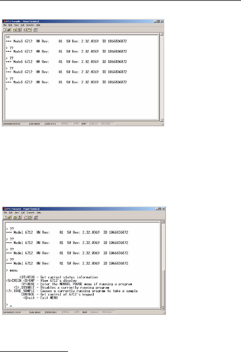
6712FR Refrigerated Sampler
Section 7 Remote Operation
7-2
Figure 7-1 Press and hold ?? to connect to the sampler
7.1.1 Menu Control Once you have remotely connected to the sampler, menu com-
mands can be entered from your computer. These menu com-
mands are listed in Table 7-1.
To access the menu commands, type MENU at the “>” prompt
and press ENTER. The screen will return a list of the available
options. Note that the current state of the controller will
determine the available menu options. Then, type the desired
command(s), confirming with ENTER.
Figure 7-2 Example list of remote menu commands
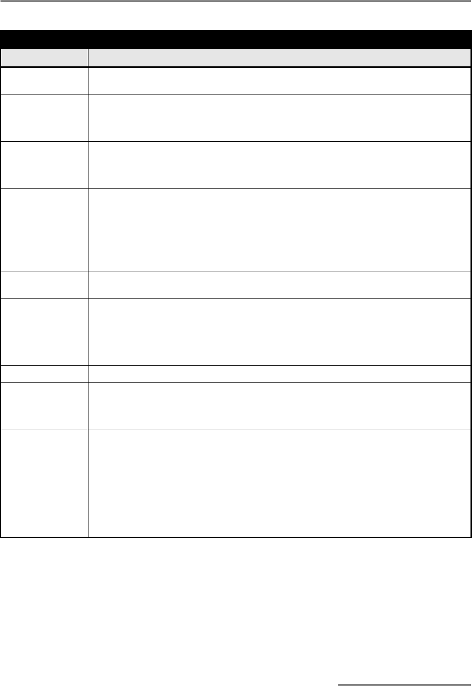
6712FR Refrigerated Sampler
Section 7 Remote Operation
7-3
Sampling reports You can retrieve the sampling reports at any time using the same
serial connection. Type “Q” to exit the menu. Then at the >
prompt, type “REPORT” and press Enter. The sampler controller
will send reports as configured.
Table 7-1 6712 Remote Menu Commands
Menu Command Description
0 or START This command will immediately start any program set to WAIT FOR PHONE CALL and cur-
rently waiting for the remote start command (see Section 4.6).
1 or RUN1 This command will load Program 1 as the sampler’s current Extended program, reset partition if
the storage interval has been changed, and run the program. RUN1 is valid when the sampler
is in standby, or when it is waiting for a start command. RUN1 will also run the current program
while in Standard programming.
2 or RUN2
3 or RUN3
4 or RUN4
These commands will load the selected program number as the sampler’s current Extended
program, reset partition data if the storage interval has changed, and run the program. They are
valid when the sampler is in standby, or when it is waiting for a start command. The commands
are available for Extended programming only.
5 or DISABLE This command is similar in functionality to a pin F low signal (a signal typically used to enable or
disable the sampler from a flow meter). At run time, the sampler starts with the sampler in the
enabled state. DISABLE is valid while a program is running. If successful, a display of REMOTE
ENABLE IS FALSE will be returned.
A Remote Disable is the highest priority disable. If the sampler is disabled with this command,
no condition other than menu command 6, ENABLE, will allow the program to become enabled
again.
6 or ENABLE This command is used to re-enable a disabled sampler. ENABLE is valid while a program is
running. If successful, a display of REMOTE ENABLE IS TRUE will be returned.
7 or TAKE_SAMPLE This command causes the sampler currently running a program to take a sample. The sample
will count as one of the program’s samples and is placed in the current bottle (Part A’s current
bottle when using two-part programming). TAKE_SAMPLE is valid while the program is run-
ning, after the start time, but not while in the MANUAL PAUSE screens. If successful, a
response similar to PUMPING XXML SAMPLE INTO BOTTLE ## will be returned. If not, a
response similar to NO SAMPLE, PROGRAM WAITING START will be returned.
ST or STATUS This command causes the sampler to return its status information and current parameter data.
SD or
SCREEN_DUMP
This command causes the sampler to return the information currently displayed on the sam-
pler’s screen. The remote screen follows the sampler’s display as the information is updated.
This mode can be used to observe from a remote location while the sampler is programmed
on-site.
P or PAUSE This command causes a sampler currently running a program to enter the MANUAL PAUSE
menu. While you are connected in this mode, the sampler keypad becomes disabled, and your
computer’s keypad will be redirected to simulate the sampler keypad. The following keys will be
activated:
<Enter>, decimal point, and number keys.
<Esc>, S, or s = STOP.
<Backspace>, L or l, and U or u = Left/Up arrows.
R or r, and D or d = Right/Down arrows.

6712FR Refrigerated Sampler
Section 7 Remote Operation
7-4
7.1.2 External Program
Control
Under external program control, the sampler operates according
to received commands. An external program can be as simple as
manually entered commands to collect a sample when needed, or
as complex as a user-developed process control program (for
SCADA or other systems) that directs sample collection
according a system’s needs.
The 6712 controller will respond to four commands:
• Turn on the sampler
• Take a sample
•Send status
• Send data
Note that commands and responses are comma-separated pairs.
The first set of alpha-characters is an identifier; the second set of
numeric characters indicates the value. The 6712 controller will
not receive and process the command unless it is followed by a
carriage return.
Turn on the sampler – If the sampler is OFF, the sampler
responds by placing itself in the ON state and returning a status
string to report the new status. (See Send Status for a
description of this string.)
The command to turn the sampler ON and return status is:
STS,2<CR>
Take a Sample – This directs the sampler to take a sample. The
command specifies how much volume to take, and which bottle to
place the sample in. The sampler responds by taking a sample
and returning a status string that reports the new status.
An example of a command to take a sample is shown below:
BTL,2,SVO,100<CR>
This example instructs the sampler to place the distributor arm
over bottle 2 (BTL,2) and take a 100 ml sample (SVO,100).
While most settings of the sampler program (start times,
enables, distribution schemes, etc.) are ignored when responding
to external commands, the sampler does rely on two program set-
tings that “configure” the sampler. These settings are:
• Number of Bottles–is used to determine the distributor
arm position and the acceptable range for the BTL
values.
• Suction Line Length–Used with liquid detection to
deliver correct sample volumes according to the SVO
value.

6712FR Refrigerated Sampler
Section 7 Remote Operation
7-5
Send Status – This command causes the sampler to return a
data string that identifies the controller and lists its current
status.
The command to send current status is:
STS,1<CR>
The status is received as pairs of comma-separated identifiers
and values. A complete description of each pair is listed below.
MO,6712, is the model number of the sampler.
ID,2424741493, is the sampler’s unique ID number.
TI,35523.50000, is the sampler’s current time, shown in a
date-time format based on the number of days since
00:00:00 1-Jan-1900, and the time shown as a fraction.
The possible states returned by the STS,1 command are:
1 = WAITING TO SAMPLE.
4 = POWER FAILED (for short time after power is
restored).
5 = PUMP JAMMED (must be resolved before continu-
ing).
6 = DISTRIBUTOR JAMMED (must be resolved before
continuing).
9 = SAMPLER OFF.
12 = SAMPLE IN PROGRESS.
20 = INVALID COMMAND. Possible causes may be:
· identifier code is not supported.
· bottle requested is not in current configuration
· sample volume requested is outside its range
(10 - 9990 ml)
· day (Set_Time) must be 5 digits and more
recent than 1977
21 = CHECKSUM MISMATCH. (see “Optional check-
sum” on page 7-8)
22 = INVALID BOTTLE. (bottle requested is not in the
current configuration)
23 = VOLUME OUT OF RANGE. (the sample volume
requested is outside its range (10-9990 ml)
STI,35523.41875, is the most recent sample time.
BTL,2, is the bottle that received the most recent sample.
SVO,100, is the most recent sample’s volume.
SOR,0, is the results of attempting the most recent sample.
The possible results are:
0 = SAMPLE OK
1 = NO LIQUID FOUND
2 = LIQUID LOST (not enough liquid)
3 = USER STOPPED (using the Stop Key)
4 = POWER FAILED
5 = PUMP JAMMED
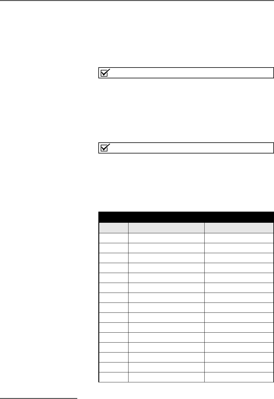
6712FR Refrigerated Sampler
Section 7 Remote Operation
7-6
6 = DISTRIBUTOR JAMMED
8 = PUMP LATCH OPEN
9 = SAMPLER SHUT OFF (while sampling)
11 = NO DISTRIBUTOR
12 = SAMPLE IN PROGRESS
CS,xxxx is the byte-by-byte sum of the entire string
“MO,...,CS,” (see “Optional checksum” on page 77-8)
Note
For commands that are not understood (INVALID COMMAND
or CHECKSUM MISMATCH) or when no samples have been
taken, the most recent bottle information is left off the response
string.
Send Data – This command causes the sampler to return the
Send Status appended with data from any module, rain gauge, or
SDI-12 device. Refer to Table 7-2 to interpret the returned string.
Note
This returns the same data as the programmable software
option Serial Output, as described in Section 5.18.6 of this
manual.
The command to send data is:
DATA<CR>
Table 7-2 Serial Data Codes
Identifier Parameter Units
B?1Bottle number and time days since 1-Jan-1900
CR Current day’s rain tips2
CS3Checksum unsigned long
DE Description 6712 Sampler
FL Flow cubic meters per second
ID Unit specific identifier 10 digit unsigned long
LE Level meters
MO Model 6712
PE Percent percent of full scale
PH pH none
PR Previous day’s rain tips2
RA Rain tips2
RTE Refrigerator Temperature degrees celsius
SS Sampler enable state logical
TE Temperature degrees celsius
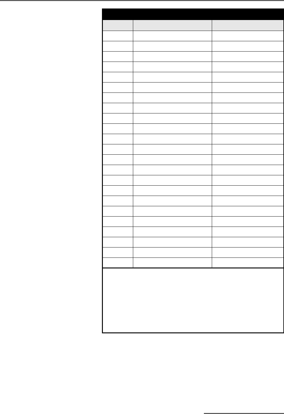
6712FR Refrigerated Sampler
Section 7 Remote Operation
7-7
TI Current time days since 1-Jan-1900
VE Velocity meters per second
VO Volume cubic meters
VSI Velocity signal strength percent
VSP Velocity spectrum strength percent
CO_ 4Conductivity milliseimens per centimeter
DO_ 4Dissolved oxygen milligrams per liter
PH_ 4pH none
SA_ 4Salinity parts per thousand
SP_ 4Specific Conductance milliseimens per centimeter
TD_ 4Total Dissolved Solids grams per liter
TE_ 4Temperature degrees Celsius
OR_ 4Oxidation reduction potential millivolts
LE_ 4Level meters
MM_ 4Ammonium-nitrogen milligrams nitrogen per liter
MA_ 4Ammonia-nitrogen milligrams nitrogen per liter
NI_ 4Nitrate-Nitrogen milligrams nitrogen per liter
TB_ 4Turbidity nephelometric turbidity units
CL_ 4Chloride milligrams per liter
CP_ 4Chlorophyll micrograms per liter
FL_ 4Flow rate cubic meters per second
VO_ 4Flow volume cubic meters
xxD_ 4, 5 Other data not listed above
1The three most recent samples will have entries as B?. The “?” will be
the first bottle number in the set. If the sample is a grab sample, it will
be shown as B0.
2Rainfall tips roll over every 256 counts.
3The checksum does not include the checksum, carriage return, and
linefeed. The string is terminated with <CR><LF>.
4A “_” in the identifier indicates an SDI-12 address.
5“XX” matches the data label for the SDI-12 parameter.
Table 7-2 Serial Data Codes (Continued)
Identifier Parameter Units
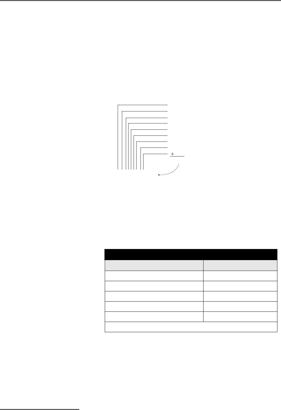
6712FR Refrigerated Sampler
Section 7 Remote Operation
7-8
Optional checksum Optionally, commands to the sampler can be validated using a
checksum. Checksum validation can avoid problems caused by
faulty program control or communication lines. When using the
checksum, add the CS identifier and a comma at the end of the
command, and the checksum value of the string up to the last
comma. For example, the command with checksum validation to
turn the sampler on would appear as:
STS,2,CS,582<CR>
The numeric value of each character is its ASCII equivalent
expressed in decimal format. The checksum of “582” was calcu-
lated as shown below.
7.1.3 Remote Control of
Sampler Keypad
To control the sampler keypad remotely, type CONTROL at the
“>” prompt and press ENTER. The sampler display appears on
your computer monitor as you step through the programming
screens. While in this mode, the computer keys will be redirected
to simulate the sampler’s keypad, and the sampler keypad itself
will be disabled to avoid any conflict. The active keys and their
corresponding functions are given in Table 7-3.
STS,2,CS,582
83
84
83
44
50
44
67
83
44
582
Table 7-3 Remote Control of Sampler Keypad
Computer Sampler
<Esc>, S, s STOP
L,l,U,u, <Backspace> Left / Up
R, r, D, d Right / Down
O, o ON
<Enter>, arrows, decimal, numbers Same as sampler
NOTE: You will not be able to turn the sampler off remotely.
6712FR Refrigerated Sampler
Section 7 Remote Operation
7-9
7.2 Telephone Commands 6712 controllers equipped with an internal voice modem can be
operated using telephone commands. This factory-installed
option includes a 12 ft (3.6 m) modem cable.
After connecting to the sampler from a touch-tone telephone,
command numbers may be entered from the telephone’s keypad,
followed by the (pound) button. The commands are listed in
Table 7-4.
To use telephone commands:
1. Dial the sampler’s telephone number. When the sampler
connects, it answers with “Teledyne Isco Sampler Site
[number].” If the sampler does not receive a touch-tone
command in five seconds, it assumes that a computer
modem has called and initiates the modem connect
sequence. If this occurs you must hang up and try again.
2. Enter the command. For example, to run program 1, press
.
3. If the command is valid for its current state of operation,
the sampler responds with “[command number], please
acknowledge.” If the command is not valid the sampler
responds with the command number followed by three
quick beeps. Enter a valid command.
4. Acknowledge the valid command by pressing the number.
For the example, press .
5. If the number is incorrect, the sampler responds with your
entry followed by three quick beeps. You must re-enter the
command (step 2).
6. After the command is confirmed, the sampler replies with
“[command number] acknowledge” and executes the com-
mand.
To enter additional commands, repeat steps 2 through 5. The
sampler will hang up after ten seconds of quiet time.
#
1 #
1
Table 7-4 6712 Remote Phone Commands
Phone
Command Name Description
Start This command will immediately start any program set to WAIT FOR PHONE
CALL and currently waiting for the remote start command (see Section 4.6).
Load and Run
Program 1
This command will load Program 1 as the sampler’s current Extended pro-
gram, reset partition if the storage interval has been changed, and run the pro-
gram. RUN1 is valid when the sampler is in standby, or when it is waiting for a
start command. RUN1 will also run the current program while in Standard pro-
gramming.
Load and Run
Program 2, 3, or 4
These commands will load the selected program number as the sampler’s cur-
rent Extended program, reset partition data if the storage interval has
changed, and run the program. They are valid when the sampler is in standby,
or when it is waiting for a start command. The commands are available for
Extended programming only.
0 #
1 #
2#
3 #
4#
6712FR Refrigerated Sampler
Section 7 Remote Operation
7-10
Disable This command is similar in functionality to a pin F low signal (a signal typically
used to enable or disable the sampler from a flow meter). At run time, the sam-
pler starts with the phone enable in the enabled state. PHONE DISABLE is
valid while a program is running. If successful, a reply of REMOTE ENABLE IS
FALSE will be returned.
A Remote Disable is the highest priority disable. If the sample is disabled with
this command, no condition other than command 6#, ENABLE, will allow the
program to become enabled again.
Enable This command is used to re-enable a phone-disabled sampler. PHONE
ENABLE is valid while a program is running. If successful, a reply of REMOTE
ENABLE IS TRUE will be returned.
Grab Sample This command causes the sampler currently running a program to take a sam-
ple. The sample will count as one of the program’s samples and is placed in
the current bottle (Part A’s current bottle when using two-part programming).
TAKE_SAMPLE is valid while the program is running, after the start time, but
not while in the MANUAL PAUSE screens. If successful, a response similar to
PUMPING XXML SAMPLE INTO BOTTLE ## will be returned. If not, a
response similar to NO SAMPLE, PROGRAM WAITING START will be
returned.
Table 7-4 6712 Remote Phone Commands (Continued)
Phone
Command Name Description
5 #
6 #
7 #

8-1
6712FR Refrigerated Sampler
Section 8 Maintenance
This section describes how to maintain and troubleshoot your
6712FR sampler. If you think your unit requires repair, or if you
have questions concerning its operation or maintenance, contact
Teledyne Isco’s Technical Service Department:
Phone: (800) 228-4373
(402) 464-0231
FAX: (402) 465-3022
E-mail: IscoService@teledyne.com
8.1 Maintenance
Checklist
• Clean the condenser coil annually.
• Clean the refrigerator’s air filter every 3 months.
• Clean the refrigerator interior and exterior periodically.
• Inspect the pump tube for wear. Replace it if necessary.
• Clean the pump tubing housing.
• Change the suction line if necessary.
• Clean the bottles, suction line, strainer and pump tube.
• Check the humidity indicator.
• Check the controller’s internal battery status and
replace the battery every five years.
• If the keypad label has bubbles under it, the air inside
the controller has expanded. To release this pressure,
unscrew the flow meter cable or connector cap on the
back of the controller. Push down on the label to force
the air out, then re-tighten the cable connector or cap.
8.2 Cleaning Guidelines
8.2.1 Refrigerator The refrigerator’s exterior may be periodically cleaned with
soapy water using a sponge or nonmetallic brush to keep it free
of corrosive solutions, grease, oil, etc. After cleaning, it should be
wiped dry. Automotive wax may be applied to the interior and
exterior surfaces to make them easier to clean and more
resistant to corrosion. Do not direct a hose spray toward the
underside or into the front grill of the refrigerator. The vacuum
formed plastic refrigerator interior may also be cleaned with
soap and water as necessary.
Because the refrigerator uses a forced-air system, dust and
debris will collect on the condenser coil and surrounding areas. If
the refrigerator is not cleaned periodically, damage due to over-
heated components may result.

6712FR Refrigerated Sampler
Section 8 Maintenance
8-2
8.2.2 Controller When necessary, clean the controller with warm soapy water. To
prevent moisture damage, always cap the connectors at the back
of the controller tightly. Keep the controller power cable con-
nected, or replace the protective cap (shipped with the sampler)
over the power source connector.
Make sure the two pump drain holes (located on the bottom
right-hand side of the pump, beneath the pump band) are open
and free of debris or buildup.
8.2.3 Sample Bottles The sample bottles have a wide mouth to facilitate cleaning.
Wash them with a brush and soapy water, or use a dishwasher.
You can autoclave the glass bottles.
8.2.4 Suction Line, Pump
Tube, and Discharge
Tube
Clean the suction line, pump tube, and discharge tube by placing
the end of the suction line in a cleaning solution and pumping it
through the delivery system. Rinse with clean water. If these
items are severely contaminated, discard them. For critical sam-
pling applications, refer to Section 8.3, Cleaning Protocols for
Priority Pollutants.
8.2.5 Strainer Clean the strainer with a brush and soapy water.
8.2.6 Air Filter The air filter prevents dust, lint, and other debris from circu-
lating around the cooling system. Clean the filter about every 3
months; more frequently under severe operating conditions.
To remove the filter:
1. Disconnect power from the refrigerator.
2. Remove the screws securing the refrigerator’s grille. (See
Appendix D Replacement Parts.)
3. Remove the grille and filter.
4. Steam clean the filter or wash it in hot, soapy water. After
washing, treat the filter with a standard filter coat.
8.2.7 Condenser Clean the condenser and surrounding areas annually; more fre-
quently under severe operating conditions.
1. Disconnect power from the refrigerator.
2. Remove refrigerator’s back panel. (See Appendix D,
Replacement Parts).
3. Vacuum the fan, compressor, and surrounding areas.
4. Check the fan for freedom of movement. If the fan and fan
motor do not rotate freely, replace the motor. (You cannot
oil the sealed fan motor bearings.)
5. Remove the front grille and filter. Vacuum the condenser
coil and surrounding areas.
6. Clean the filter before replacing it.
7. Replace the back panel and front grille.

6712FR Refrigerated Sampler
Section 8 Maintenance
8-3
8.3 Cleaning Protocols for
Priority Pollutants
Clean sampling equipment is essential for valid laboratory
analysis. Teledyne Isco recommends that you develop cleaning
protocols in consultation with a laboratory analyst when
designing the monitoring program. For example, to clean sample
bottles, suction line, and pump tubes, Lair (1974) suggests these
protocols used by USEPA Region IV Surveillance and Analysis
field personnel engaged in NPDES compliance monitoring. The
protocols are based on U.S. Environmental Protection Agency
Publications EPA-600/4-77-039 (Sampling of Water and Waste-
water by Dr. Phillip E. Shelley).
8.3.1 Isco Glass Sample
Bottles
1. One spectro-grade acetone rinse.
2. Dishwasher cycle (wash and tap water rinse, no detergent).
3. Acid wash with at least 20 percent hydrochloric acid.
4. Dishwasher cycle (wash and tap water rinse, no detergent).
5. Replace in covered Isco tubs.
8.3.2 Vinyl Suction Line • Use new suction line for each new sampling setup,
therefore, no cleaning is required.
• Use PTFE suction line when sampling for organic
compounds.
8.3.3 PTFE Suction Line 1. Rinse twice with spectro-grade acetone.
2. Rinse thoroughly with hot tap water using a brush, if pos-
sible, to remove particulate matter and surface film.
3. Rinse thoroughly three times with tap water.
4. Acid wash with at least 20 percent hydrochloric acid.
5. Rinse thoroughly three times with tap water.
6. Rinse thoroughly three times with distilled water.
7. Rinse thoroughly with petroleum ether and dry by pulling
air through the line.
8. Dry overnight in a warm oven (use an oven temperature of
lower than 150° F), if possible.
9. Cap ends with aluminum foil.
8.3.4 Isco Pump Tube 1. Rinse by pumping hot tap water through the tube for at
least 2 minutes.
2. Acid wash the tube by pumping at least a 20 percent solu-
tion of hydrochloric acid through the tube for at least 2
minutes.
3. Rinse by pumping hot tap water through the tube for at
least 2 minutes.
4. Rinse by pumping distilled water through the tube for at
least 2 minutes.
6712FR Refrigerated Sampler
Section 8 Maintenance
8-4
Note
For critical sampling applications, consider replacing the suc-
tion line, pump tube, and discharge tube. Replacement elimi-
nates the possibility of any cross contamination from previous
sampling sites.
8.4 Maintenance Screens When you select OTHER FUNCTIONS from the main menu, and
then select Maintenance, the following screen will be displayed:
Using these options, you can set the sampler’s time and date, set
the number of pump counts for the pump tube warning, reset the
battery warning for the internal battery, and run a set of diag-
nostic tests for troubleshooting purposes.
8.4.1 Set Clock
Teledyne Isco ships samplers from the factory with the clocks set
to the correct Central Standard Time. Reset the clock when
installing the sampler in a different time zone, for daylight
savings time, or when needed.
When setting the clock and calendar, use a 24-hour clock for
times and the day-month-year format for dates. The illustration
at the left shows blanks for each position that accepts an entry.
The positions are called fields. When this screen appears on your
sampler, the fields will contain the sampler’s current settings for
the time and date.
• To move from one field to another without changing the
setting, press the arrow keys. Use this technique when
you want to change only one or two settings.
• Change the setting by typing a new number. Press ↵ to
accept the new setting.
For example, to enter 2:00 p.m. (2:00 p.m is 14:00 on a 24-hour
clock), type 14. Press ↵. Next, type 0 (zero) for the minutes, and
press ↵. To enter a date, such as January 22, 2001, type: 22 ↵
01 ↵ 01 ↵ .
SET CLOCK
PUMP TUBE ALARM
INTERNAL BATTERY
DIAGNOSTICS
Entering Times and Dates
ENTER TIME AND DATE:
HH:MM DD-MON-YY
__:__ __-__-__
•Move from one field to
another by pressing the
arrow keys.
•Change a setting in a field
by typing a number. Press ↵
to accept the new setting.
6712FR Refrigerated Sampler
Section 8 Maintenance
8-5
8.4.2 Pump Tube Alarm The sampler tracks the pump counts in both the forward and
reverse cycles with a resettable counter. When the counter
reaches the default count of 1,000,000 or the count you have
entered, the sampler displays a message, “WARNING!
REPLACE PUMP TUBE.” The message appears each time you
turn the sampler on or run a program until you reset the counter.
After replacing the pump tube (see page 8-9), reset the count to
zero so the sampler can begin tallying the pump counts for the
new tube. Replacing the pump tube does not reset the counter.
WARNING
Pump may actuate without warning. To avoid injury,
sampler must be off when pump housing cover is removed
for inspection or tubing replacement.
Experience may suggest a significantly different pump tube life.
You can change the alarm count to represent the pump tube life
for your application. The example below shows how to set the
alarm count and reset the pump counts.
Table 8-1 Setting the Clock and Calendar
1
RUN
PROGRAM
VIEW REPORT
OTHER FUNCTIONS
Select OTHER FUNCTIONS.
2
MAINTENANCE
MANUAL FUNCTIONS
PROGRAMMING STYLE
Select MAINTENANCE.
3
SET CLOCK
PUMP TUBE ALARM
INTERNAL BATTERY
DIAGNOSTICS
Select SET CLOCK.
4
ENTER TIME AND DATE:
HH:MM DD-MON-YY
14:00 22-JAN-01
Enter the time and date.
5
SET CLOCK
PUMP TUBE ALARM
INTERNAL BATTERY
DIAGNOSTICS
Press STOP to return to the main
menu.
6712FR Refrigerated Sampler
Section 8 Maintenance
8-6
8.4.3 Internal Battery
Warning
The internal lithium battery preserves the sampler’s memory
when power is removed. For an explanation of how to replace the
lithium battery, go to Section 8.8
.
Table 8-2 Resetting the Pump Counter
1
RUN
PROGRAM
VIEW REPORT
OTHER FUNCTIONS
Select OTHER FUNCTIONS.
2
MAINTENANCE
MANUAL FUNCTIONS
PROGRAMMING STYLE
HARDWARE
Select MAINTENANCE.
3
SET CLOCK
PUMP TUBE ALARM
INTERNAL BATTERY
DIAGNOSTICS
Select PUMP TUBE ALARM.
41024000 PUMP COUNTS,
WARNING AT 1000000
The sampler displays this screen briefly to give you the current pump-count
information. The first line shows you the pump counts tallied since the
counter was last reset. The second line shows the current alarm setting.
5
1024000 PUMP COUNTS,
RESET PUMP COUNTER?
YES NO
To reset the counter to zero, select YES. Always reset the counter after
replacing a pump tube. Select NO when merely checking the current count.
6
WARNING AT 1000000
PUMP COUNTS
(1 - 99)00000)
If necessary, change the pump-count alarm setting by typing the first two
digits of the new setting. The sampler accepts entries between 1 and 99. For
example, to increase the count to 1,500,000, enter 15.
7
SET CLOCK
PUMP TUBE ALARM
INTERNAL BATTERY
DIAGNOSTICS
Press STOP to return to the main menu.
Table 8-3 Checking and Replacing the Internal Battery
1
RUN
PROGRAM
VIEW REPORT
OTHER FUNCTIONS
Select OTHER FUNCTIONS.
2
MAINTENANCE
MANUAL FUNCTIONS
PROGRAMMING STYLE
HARDWARE
Select MAINTENANCE.
3
SET CLOCK
PUMP TUBE ALARM
INTERNAL BATTERY
DIAGNOSTICS
Select INTERNAL BATTERY.
4
WARNING!
REPLACE INTERNAL
BATTERY BEFORE
17-OCT-97
The sampler displays this screen briefly to show you the expiration date.

6712FR Refrigerated Sampler
Section 8 Maintenance
8-7
8.4.4 Diagnostics The sampler has several self-diagnostic tests that check the
memory (both the RAM and ROM), pump, and the distributor
arm position. It also contains screens that let you reset the
sampler’s program settings and memory to factory settings.
You do not need to run the diagnostic tests on a routine basis.
The diagnostic tests are a troubleshooting tool; Teledyne Isco’s
Customer Service department staff may ask you to run these
tests when they work with you in diagnosing problems with your
sampler.
Access the diagnostic screens by selecting Other Functions from
the main menu, then Maintenance, and Diagnostics. The unit
will automatically test the memory and display; you can choose
whether it tests the pump and distributor, and whether it reini-
tializes the unit to its original factory settings.
5
DID YOU REPLACE THE
INTERNAL BATTERY?
YES NO
After replacing the battery, select YES. Select NO only if checking the
expiration date.
Resetting the alarm directs the sampler to calculate a new expiration date,
five years in the future. If you reset the alarm without replacing the battery,
the sampler will not be able to alert you to the battery’s impending
expiration.
6
SET CLOCK
PUMP TUBE ALARM
INTERNAL BATTERY
DIAGNOSTICS
Press STOP to return to the main menu.
Table 8-3 Checking and Replacing the Internal Battery (Continued)
6712FR Refrigerated Sampler
Section 8 Maintenance
8-8
Memory Test – Screens 1 and 2 at left show you the diagnostic
tests for the unit’s memory. If either screen shows you a message
saying that the memory failed the test, contact Teledyne Isco’s
Customer Service.
Display Test – Screen 3 shows you the display test. You should
see the test pattern illustrated in the screen. If the pattern does
not match the illustration, the display or its circuitry require
repair.
Pump Test – Screen 4 lets you start the pump test by selecting
YES. As the sampler runs the test, it first runs the pump forward
for a short period. Next, it displays an ON/OFF ratio number.
After displaying the forward pumping ratio, the sampler reverses
the pump to obtain a purge ratio. The acceptable range is
between 0.80 and 1.25. If either ratio is outside the acceptable
range, the pump requires repair. You do not need to pump liquid
while running the test, and you can run the test with or without
a tube in the pump.
PLEASE WAIT!
. . . ‘RAM’ PASSED TEST
PLEASE WAIT!
. . . ‘ROM’ PASSED TEST
•If RAM or ROM fails the test,
the sampler will report that
‘RAM’ (or ’ROM’) FAILED
TEST. Contact Teledyne Isco’s
Customer Service for assis-
tance.
ABCDEFGHIJKLMNOPQRST
ABCDEFGHIJKLMNOPQRST
ABCDEFGHIJKLMNOPQRST
ABCDEFGHIJKLMNOPQRST
TEST PUMP?
YES NO
PUMPING . . .
PUMPING . . .
ON/OFF RATIO = _.__
PURGING . . .
PURGING . . .
ON/OFF RATIO = _.__
TEST DISTRIBUTOR
YES NO
FINDING ARM FLEXURE
NOW AT BOTTLE __
RE-INITIALIZE?
YES NO
6712FR Refrigerated Sampler
Section 8 Maintenance
8-9
CAUTION
Tests indicate that the pump produces sound levels in excess
of 85db at one meter. Prolonged exposure to this sound level
could result in hearing loss and requires the use of protective
ear plugs.
Distributor Test – The distributor test is provided for factory
personnel to verify the distributor’s position as it rotates through
the 24 positions. (screens 9 through 11). The distributor arm
flexes slightly when it contacts the stop, and the sampler mea-
sures this flexure. The sampler uses this measurement to
position the arm accurately over each bottle.
Reinitialize Controller – The sampler allows you to reset all
the program settings to the settings shipped with the sampler
(screen 12). Reinitializing also clears the memory that stores the
sampler’s event log and module data. Use this option cau-
tiously.
8.5 Replacing the Pump
Tube
Replace the pump tube only with Teledyne Isco’s 6712 pump
tubing. Other pump tubes will not work. The 6712 pump
tubing is easily recognized by the blue alignment collars.
Improper pump tubes include those made for Teledyne Isco’s
other samplers (3700, GLS, etc.) and tubing from non-Teledyne
Isco vendors. Also note that the discharge tube is not the same as
the pump tube. You could experience several problems if you
install the wrong pump tubing:
• The sampler will not pump the liquid.
•Pump jams
• Inaccurate sample volumes
• Faulty liquid detection
Inspect the pump tube periodically. Replace the tube when it
cracks or appears worn. Inspect the tube frequently when the
sample liquid contains a high percentage of suspended or
abrasive solids.
Note
The importance of regular tubing replacement cannot be over-
stated. The key is to replace the tube before failure, not after.
When a pump tube ruptures, grit and other abrasive debris can
be driven into the pump shaft seal. Over time, this abrasive
material will degrade the pump seal, jeopardizing the
NEMA 4x 6 rating of the controller.
Failure to maintain the pump tube may result in permanent
damage to the sampler. Check the condition of the pump tube
regularly and if the tube shows signs of fatigue or wear,
replace it immediately. A properly maintained sampler will pro-
vide the years of reliable service that is expected of an Isco
Sampler.
6712FR Refrigerated Sampler
Section 8 Maintenance
8-10
8.5.1 Checklist For
Replacing Pump Tube
1. Disconnect power from the sampler.
2. Loosen the liquid detector’s cover by unscrewing the black
knob on top of the detector. Unlatch the pump band. (The
band is the rounded metal band that holds the tube in the
pump.)
3. Pull the tube away from the bulkhead fitting. Pull it from
the pump and detector.
4. Clean the pump rollers and the inside of the pump band.
5. Thread the new tubing through the pump so that the tube
follows its natural curve around the pump rollers. You may
need to move the pump rollers to make the installation
easier.
6. The blue collars on the tube help align the tube in the
detector and pump. Align the tube by placing the collars in
the grooves inside the liquid detector.
7. Close the detector’s cover and tighten the black knob. Close
the pump strap and latch it.
8. Reset the pump-tube counter. (See example in table 8-2.)
9. Take a “dry” grab sample to test the tube installation.
WARNING
The pump’s safety lock prevents the sampler from running
the pump when the pump band is open. DO NOT tamper
with the safety mechanism. The pump is extremely
powerful. The pump rollers can injure you severely if the
sampler activates the pump while you are working on it or
inside it. Disconnect power from the sampler before
replacing the pump tube.
Note
To extend the pump tube life:
• Always use Isco pump tubes.
• Install the tube properly, aligning the blue collars correctly in
the liquid detector’s grooves.
• Follow the natural curve of the tube when wrapping the tube
around the pump rollers.
• Minimize the line rinses and sampling retries in the sampling
programs
• Use the shortest possible suction line.
Conditions that shorten tube life:
• Improper installation.
• Abrasive materials suspended in sample liquid.
• Frequent line rinses.
• Long purge cycles, such as those used with long suction
lines.
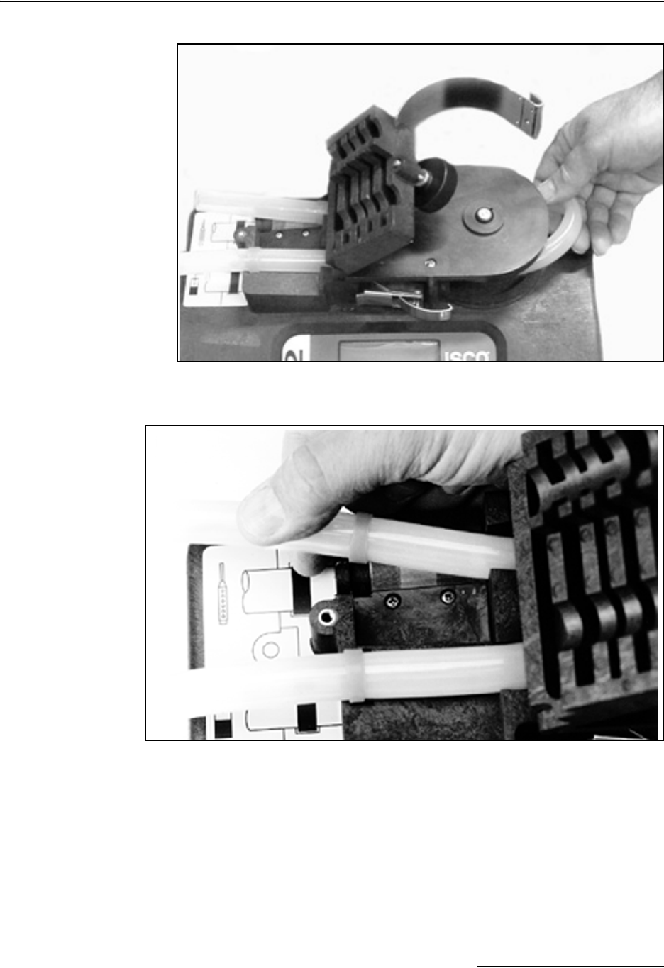
6712FR Refrigerated Sampler
Section 8 Maintenance
8-11
Figure 8-1 Removing and Replacing the Pump Tube
Figure 8-2 Placing the Pump Tube in the Liquid Detector
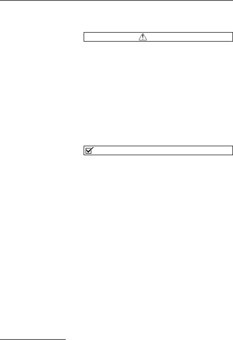
6712FR Refrigerated Sampler
Section 8 Maintenance
8-12
8.6 Opening the
Controller Case
You will need to open the controller case to gain access to:
• The desiccant bag that dries the controller’s interior
• The battery that provides backup power to the controller
CAUTION
The circuit boards can be damaged from a discharge of static
electricity. Always use an antistatic mat when opening the con-
troller to protect the circuit boards.
To open the case:
1. Pull the discharge tube and pump tube away from the
bulkhead fitting.
2. Remove the distributor arm by unscrewing the nut that
attaches the arm to the distributor shaft. DO NOT
ROTATE THE DISTRIBUTOR ARM MANUALLY;
THIS WILL SEVERELY DAMAGE THE DISTRIBU-
TOR DRIVE GEARS.
3. Remove the controller from the refrigerator.
4. Open the case by removing the 11 screws that attach the
case bottom to the case top.
Note
The case top and bottom fit together with a sealed
tongue-and-groove joint. Any damage — nicks or cuts — to the
tongue, groove, or sealing gasket prevent the case from seal-
ing completely when you close it. Use extreme care when
opening the case to avoid damaging the joining surfaces.
Refer to Figure 8-3 for the location of the desiccant box. To gain
access to the main circuit board and battery, remove the two dis-
tributor connectors and the EMI shield.
8.7 Replacing the
Desiccant
A humidity indicator, labeled “INTERNAL CASE HUMIDITY,” is
located to the right of the keypad. It indicates the amount of
moisture present inside the control box. The paper indicator is
blue when the control box is dry.
The control box is a completely sealed unit. You do not need to
open the control box during normal operation. The 6712 Sam-
plers use a desiccant bag inside the controller case to prevent
moisture damage to its electronic components. Thus, the
humidity indicator should remain blue under normal conditions.
If moisture does accumulate, the numbered areas on the indi-
cator will turn light pink or white, starting with the area num-
bered “20.” This indicates that the relative humidity inside the
control box exceeds 20%. As more moisture accumulates, the
areas numbered “30” and “40” will turn light pink or white, indi-
cating relative humidities of 30% and 40% respectively.
If the 30% area of the humidity indicator turns light pink or
white, open the control unit, inspect it for leaks, and replace the
desiccant bag.
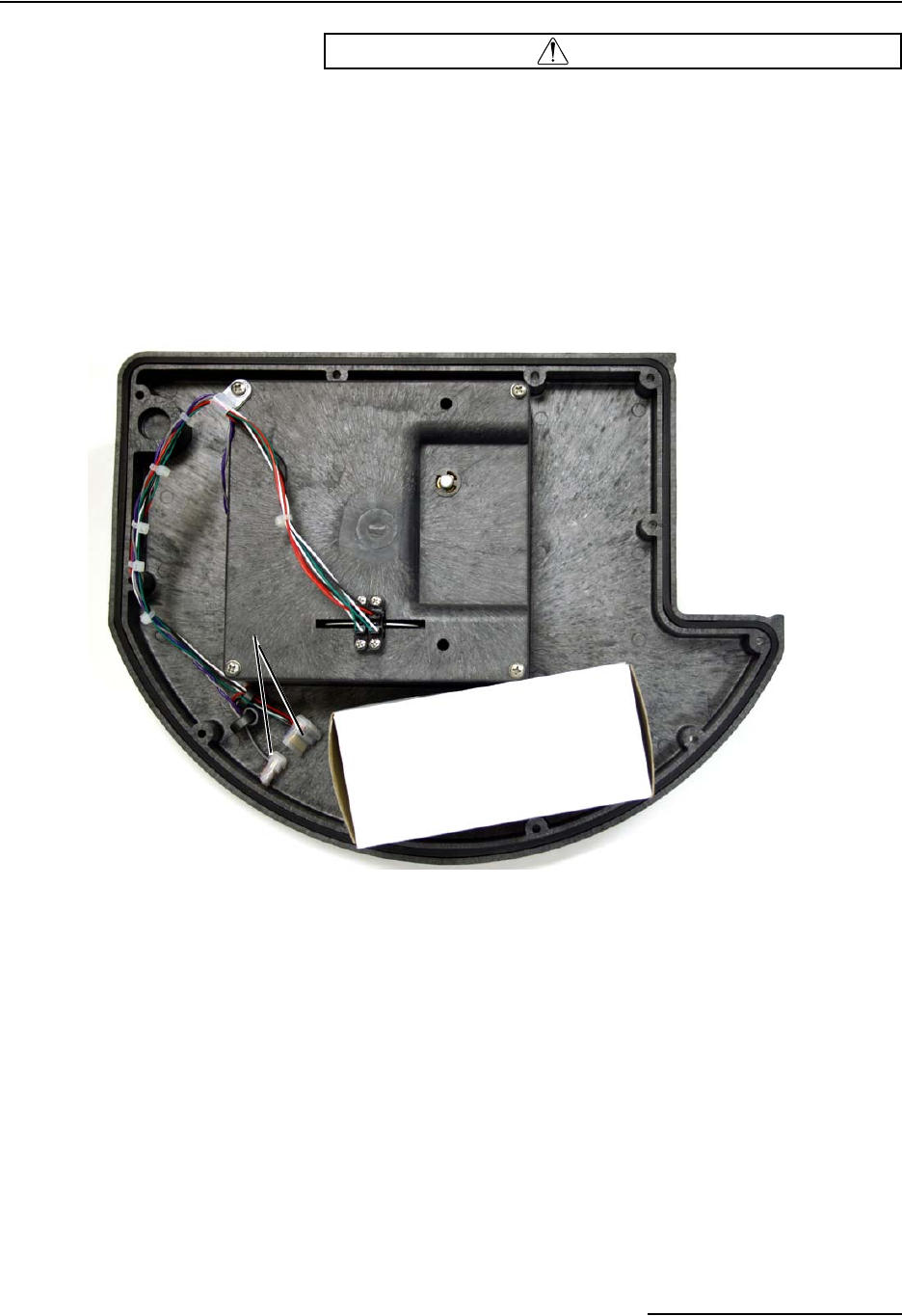
6712FR Refrigerated Sampler
Section 8 Maintenance
8-13
CAUTION
Do not attempt to reactivate the used desiccant. Reactivation
may cause desiccant to leak out of the bag, causing mechani-
cal damage inside the controller.
Follow the instructions in Opening the Controller Case in Section
8.6 to open the controller. Remove the bag from the cardboard
box (part #69-9003-518) at the front of the case and replace it
with a fresh bag of desiccant (part #099-0002-00).
Figure 8-3 Opening the Controller
Desiccant Box
Distributor
Connectors
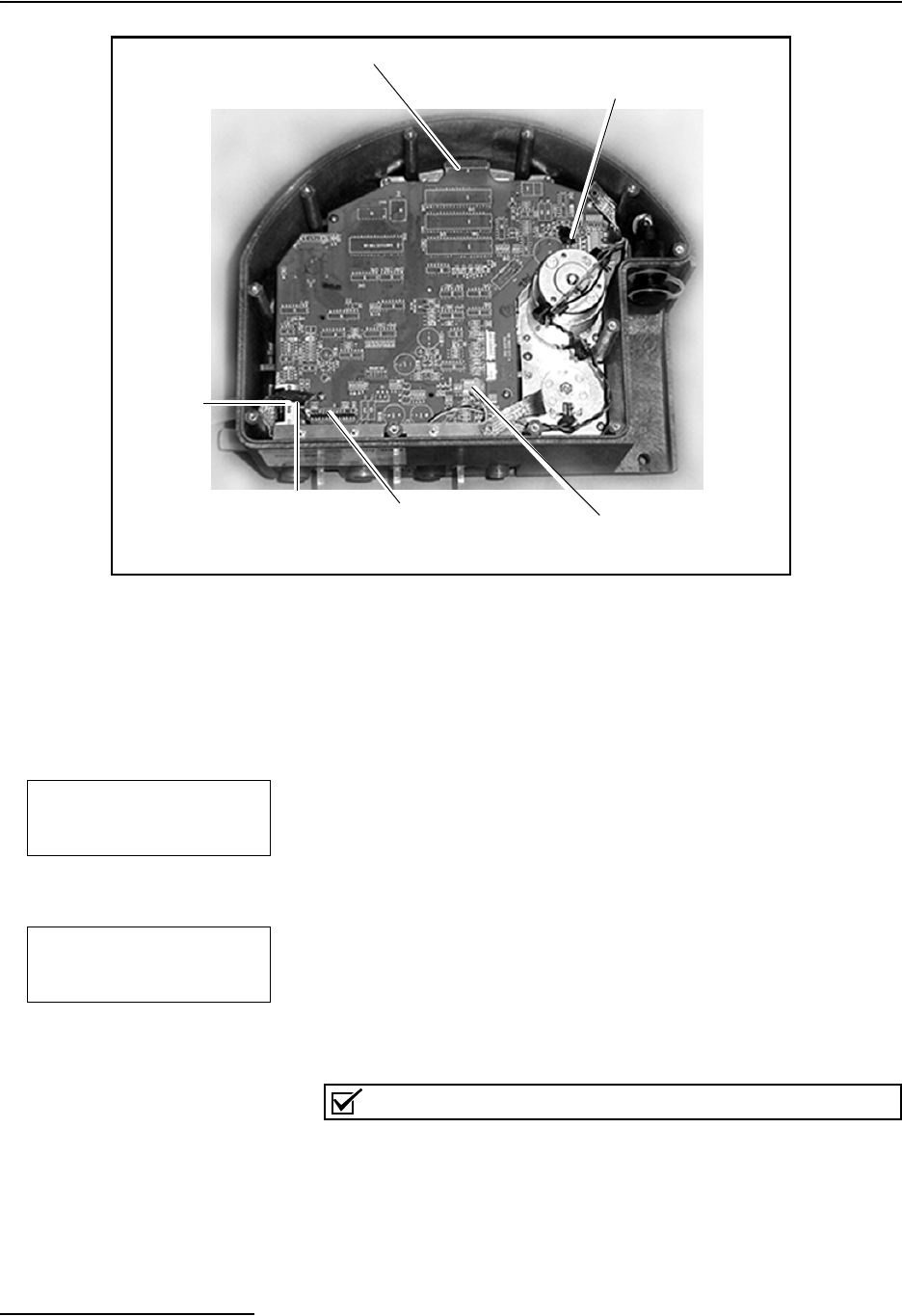
6712FR Refrigerated Sampler
Section 8 Maintenance
8-14
Figure 8-4 Main Circuit Board Connections
8.8 Replacing the Internal
Battery
A lithium battery housed inside the controller maintains power
to the sampler’s memory when the controller is disconnected
from a power source. If it discharges completely, the sampler will
lose all program settings and all data stored in memory when the
external power source is disconnected.
The battery requires replacement every five years. The sampler
keeps track of the time that has passed since the battery was
installed. To view this information, select INTERNAL BATTERY
from the Maintenance screen (see example at left). After 5
seconds, the sampler asks if you have replaced the internal
battery (see example at left).
Select YES to reset the countdown to 59 months from the current
date.
While replacing the battery, it is likely that the stored readings
will be lost and your program will revert to the default program.
Before proceeding, retrieve the stored data and record your
program settings.
Note
Teledyne Isco recommends you replace the battery every five
years, as soon as the battery warning appears. To ensure that
the replacement meets Teledyne Isco’s specifications, use only
Isco replacement batteries. (See Appendix D, Replacement
Parts.)
Keypad Connector
Module Connector
Liquid Detector
Connector Pump Count
Connector
Connector Board
Connector
Battery
Battery Status Display
WARNING!
REPLACE INTERNAL
BATTERY BEFORE
17-OCT-06
DID YOU REPLACE THE
INTERNAL BATTERY?
YES NO
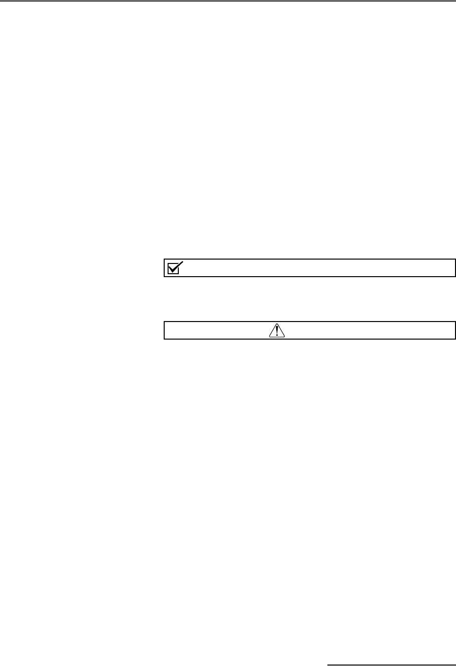
6712FR Refrigerated Sampler
Section 8 Maintenance
8-15
To replace the internal battery:
1. Open the controller case. Separate the case bottom and top
by removing the two distributor connectors.
2. Lift the desiccant box from the case.
3. Remove the EMI shield and grounding straps by loosening
the five 1/4-inch stop nuts.
4. Disconnect the module, liquid detector, and pump count
connectors from the main circuit board.
5. Remove the three screws and the 1/4-inch stud attaching
the main circuit board to the case.
6. Detach the main circuit board from the keypad connector
by pulling gently upward on the edges of the board next to
the connector. Pull the main board up until the keypad con-
nector is almost even with the edge of the case. Next,
detach the main circuit board from the connector board.
7. De-solder the lithium battery, using care to prevent dam-
age to the circuit board. Insert the replacement battery
and solder it in place.
Note
Poor soldering techniques can easily damage a printed circuit
board. The battery should be replaced by a skilled technician.
WARNING
Danger of explosion if lithium battery is incorrectly
replaced. Replace with the same type, ensuring correct
polarity. Do not dispose of used lithium battery in fire.
8. Reconnect the main circuit board to the connector board
before reconnecting it to the keypad. Replace the 1/4-inch
stud and the three screws, and reconnect the module, liq-
uid detector, and pump count connectors.
9. Replace the EMI shield and grounding straps. Reconnect
the two distributor connectors.
10. Ensure that all connections and hardware are secure.
Replace the desiccant and close the case.
11. Reset the battery alarm.
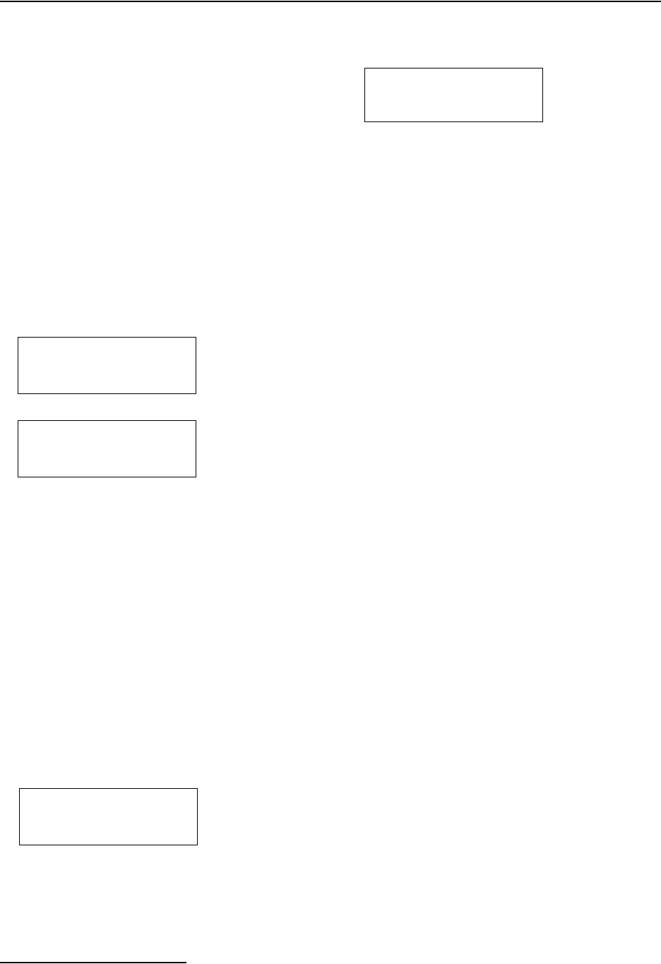
6712FR Refrigerated Sampler
Section 8 Maintenance
8-16
8.9 Error Messages If the sampler detects an error that prevents it from taking a
sample or continuing the program, it displays an error message.
There are messages for the following conditions:
Since the sampler may encounter more than one error during a
program, it does not display the messages continuously. Instead,
it records each error and the time it occurred in the Sampling
Results and Combined Results report. It alerts you to the
recorded errors by displaying the message, “ERRORS HAVE
OCCURRED DURING PROGRAM.”
If the sampler detects a low battery condition, it stops the
running program and displays the “LOW BATTERY” error
message. A low battery condition exists when five consecutive
sample events have resulted in a POWER FAILED error
message.
Fatal Error – The Fatal Error message will only show up if you
are using a multiple bottle configuration and the distributor
system fails. Failing the test can indicate any of the following
conditions:
• The distributor arm is not attached to the sampler.
• The distributor-arm stop inside the center section is
missing or broken.
• The distributor drive mechanism inside the controller is
malfunctioning.
8.10 Pump Tube Warning
Occasionally, the sampler displays a warning message to alert
you to a potential problem. The warning, REPLACE PUMP
TUBE, reminds you to check the condition of the pump tube.
Instructions regarding the pump tube can be found elsewhere in
this section.
OPERATION ERROR:
PUMP JAMMED
• PUMP JAMMED
• DISTRIBUTOR JAMMED
• PROBABLE OVERFLOW
• POWER FAILED
• LOW BATTERY
• USER STOPPED
• NO DISTRIBUTOR ARM
• NO LIQUID DETECTED
• NO MORE LIQUID
• PUMP LATCH OPEN
• SAMPLER SHUT OFF
• BOTTLE FULL
• SAMPLE IN PROGRESS
Error Messages
ERRORS HAVE OCCURED
DURING PROGRAM
FATAL ERROR
NO DISTRIBUTOR ARM
WARNING: REPLACE
PUMP TUBE
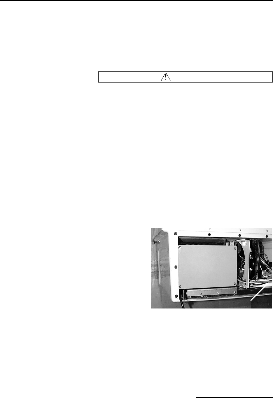
6712FR Refrigerated Sampler
Section 8 Maintenance
8-17
8.11 Servicing the
Refrigerator
Before servicing the refrigerator, disconnect it from power. This
precaution will protect you from the possibility of electric shock
when working with the refrigerator.
8.11.1 Electrical System Access the electrical and refrigeration components by removing
the nine screws on the back of the refrigerator (See Appendix D,
Replacement Parts).
WARNING
Removing the front or back panel exposes electrical and
mechanical hazards. Disconnect the power before
performing any service activities. Troubleshooting and
repair activities should be performed by a qualified
refrigeration technician.
The temperature control box assembly, which houses the ther-
mostat logic circuit board, the transformer, and the solid state
relay, is located on the left-hand side of the refrigerator base as
shown in Figure 8-5. Access to these components can be gained
by removing the four screws securing the lid of the temperature
control box. See Figure 8-6.
You can remove the temperature control box from the refrig-
erator by removing the screws from its mounting plate and dis-
connecting the wires from the backside of the box. See Figures
8-7 and 8-8.
Figure 8-5 Rear View of the 6712FR
Temperature
Control Box
Assembly
Drip Pan
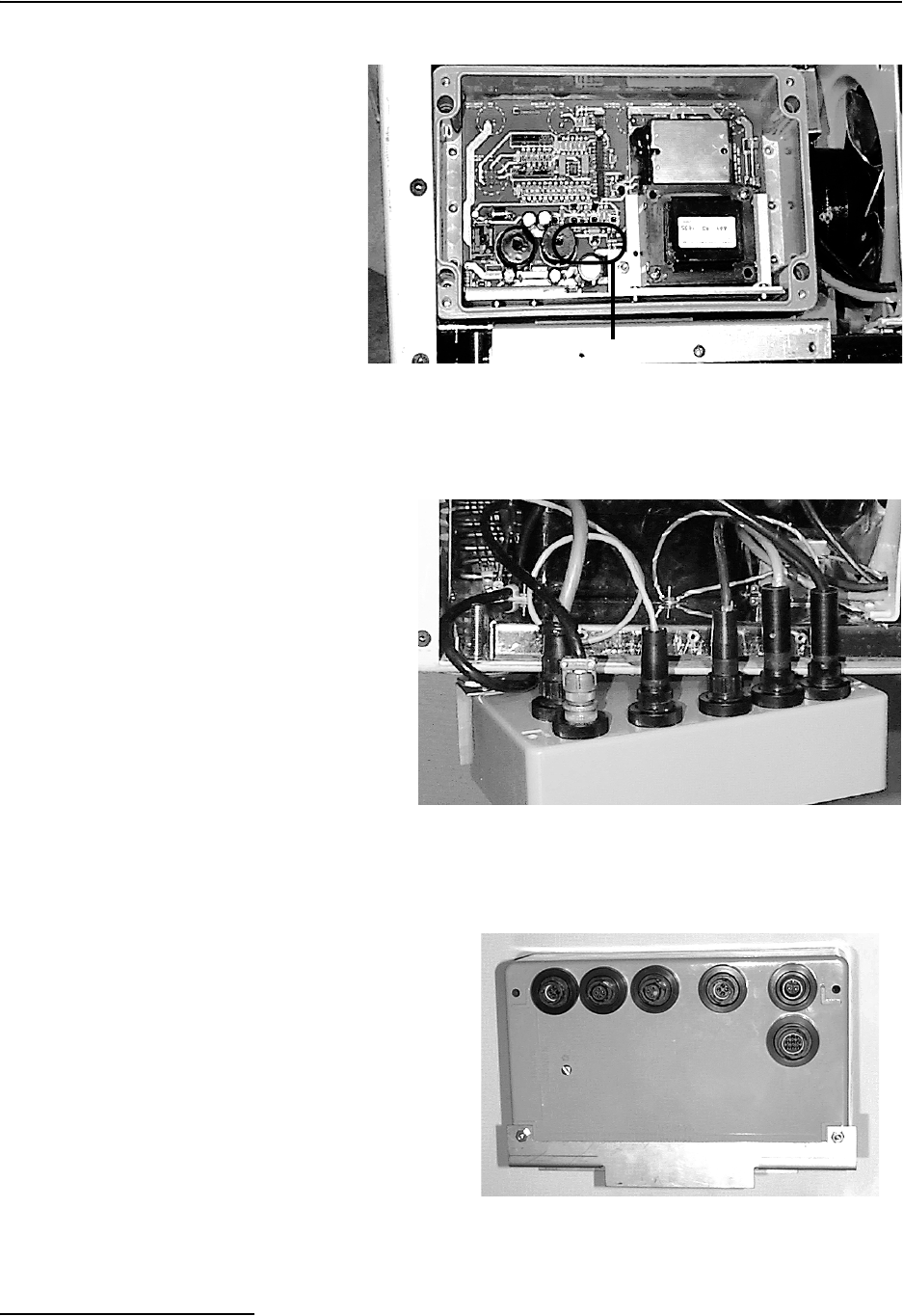
6712FR Refrigerated Sampler
Section 8 Maintenance
8-18
Figure 8-6 Thermostat Logic Circuit Board
Figure 8-7 Control Box Wiring
Figure 8-8 Control Box Connections
LEDs

6712FR Refrigerated Sampler
Section 8 Maintenance
8-19
The ambient air sensor samples the air temperature outside the
refrigerator. It is located in the temperature assembly located on
the right of the refrigerator grille. If the ambient temperature is
cold, three heaters will be turned on by the circuitry.
Two of the heaters are located on the sides of the evaporator
plate inside the refrigerator and one heater is located on the com-
pressor.
The fuse, F2, is included on the supply side of the heaters to
prevent an electrical hazard in the event of a fault in either
heater. Refer to Appendix D Replacement Parts List for
replacement fuse part numbers.
The heaters prevent the sample from freezing when the outside
air temperature falls below freezing. The compressor will cycle
approximately the same amount of times at cold temperatures as
at room temperatures.
The ambient air temperature signal comes from the sensor into
the circuit board. The signal is then sent to an oscillator.
Depending on the temperature, the voltage will vary. This varies
the duty cycle of the oscillator, which in turn, varies the duty
cycle of the heaters. This circuitry is linear; at 65•F the heaters
will begin to come on and at -35•F the heaters will be on continu-
ously. When the heaters are on, the internal heat LED indicator
will be lit.
The internal temperature sensor is a thermistor that samples
the internal air temperature of the refrigerator. It is mounted at
the top of the refrigerator’s interior. The internal temperature
signal comes from the sensor, through the plug in the ther-
mostat/wiring housing assembly, and into the board. The setting
on the temperature control knob comes from the potentiometer,
through the plug in the thermostat/wiring housing assembly and
into the board. If the interior of the refrigerator is warmer than
the temperature control potentiometer setting, the internal tem-
perature LED indicator will be lit. The temperature control
potentiometer is located in the thermostat/wiring housing
assembly.
The evaporator temperature sensor is mounted on the front of
the evaporator plate. The signal from the sensor comes through
the connector in the thermostat/wiring housing assembly and
into the circuit board. The evaporator temperature LED indi-
cator will be lit if the evaporator temperature is warm (and all
the frost has been melted).
The operation of the compressor and the compressor run LED
indicator is determined by the temperature control potenti-
ometer setting, the internal refrigerator temperature, and the
evaporator temperature.
It is not recommended that the user attempt any cali-
bration adjustments.
Below is the operation of a compressor cycle assuming that the
compressor is already running.
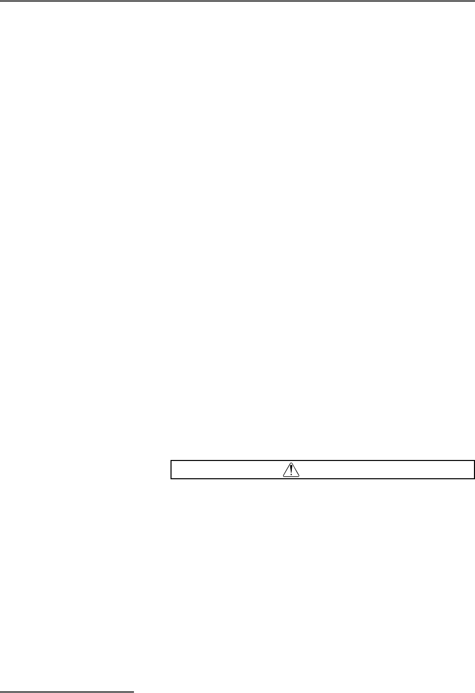
6712FR Refrigerated Sampler
Section 8 Maintenance
8-20
As the compressor runs, the temperature of the evaporator will
fall below 32•F (0•C) and the evaporator temperature indicator,
located on the circuit board, will go out. The internal temper-
ature and the compressor run indicators will both be lit. The
compressor will continue running until the internal air temper-
ature of the refrigerator reaches the temperature set on the tem-
perature control knob. Once this temperature is reached the
internal temperature indicator will go off, the compressor run
indicator will go off, and the compressor will shut off. After the
compressor shuts off, the refrigerator melts the frost that accu-
mulated on the evaporator while the compressor was running.
Once the evaporator temperature has warmed to the calibrated
temperature (approximately 2•C) the evaporator temperature
LED indicator will turn on.
When the refrigerator's internal temperature gets warmer than
the temperature setting, the internal temperature indicator will
light. When both the evaporator temperature and the internal
temperature indicators are lit, a signal is sent to the solid state
relay. This activates the refrigerator's compressor and turns on
the compressor run indicator. The compressor will continue to
run until the internal temperature indicator goes out.
If a problem with the circuitry is suspected, remember that the
compressor shuts off when the internal temperature sensor
reaches the setting on the temperature control knob. But, to turn
the compressor on, both the internal temperature sensor and the
evaporator temperature sensor must be warm. The com-
pressor/fan solid state relay may be replaced but do not
attempt to replace any other components. Otherwise, the
calibration of the circuitry will be disturbed. It is suggested that
the entire board be replaced or the board be returned to the
factory for repair.
8.11.2 Refrigeration System The refrigeration system is shown schematically in Figure 8-9.
The charge capacity of the system is 7.5 oz of R-134a refrigerant.
CAUTION
All refrigeration repair work must be performed by a qualified
refrigeration technician.
Always purge the system with nitrogen. NEVER USE AIR to
purge the system.
Always recover the refrigerant.
When recharging, do not leave a line tap in the refrigeration
system because of possible corrosion or leakage problems.

6712FR Refrigerated Sampler
Section 8 Maintenance
8-21
Figure 8-9 Refrigeration System Schematic
Equipped with external overtemperature and overload pro-
tection, the compressor may fail to start immediately when
power is momentarily interrupted or when the thermostat
setting is changed. The overload relay normally trips repeatedly
until the refrigerant pressure equalizes. This does not indicate a
malfunction.
Condenser Coil
Compressor
Capillary Tube
Evaporator Plate

6712FR Refrigerated Sampler
Section 8 Maintenance
8-22
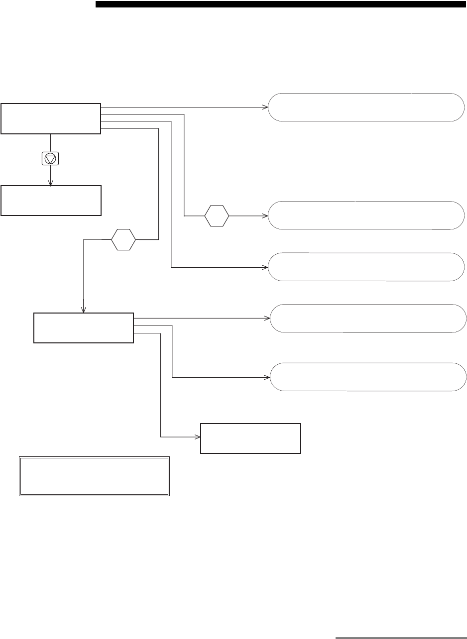
A-1
6712FR Refrigerated Sampler
Appendix A Menu Flowcharts
Figure A-1 6712 Menu Tree for Standard Programming
RUN
PROGRAM
VIEW REPORT
OTHER FUNCTIONS
MAINTENANCE
MANUAL FUNCTIONS
PROGRAMMING STYLE
PROGRAMMING STYLE:
NORMAL
QUICK VIEW/CHANGE
POWER USED:
CURRENT: _._ amp-hr
PREVIOUS: _._ amp-hr
Stop Key
Note A
Note A
Note A:
Menu access can be controlled with the optional
Program Lock. See Section 5.
See Running Programs on page 4-10.
See Manual Functions Screens on
page A-8.
See the charts on pages A-2 through A-19.
See Maintenance Screens on page A-7.
See View Report on page A-6.
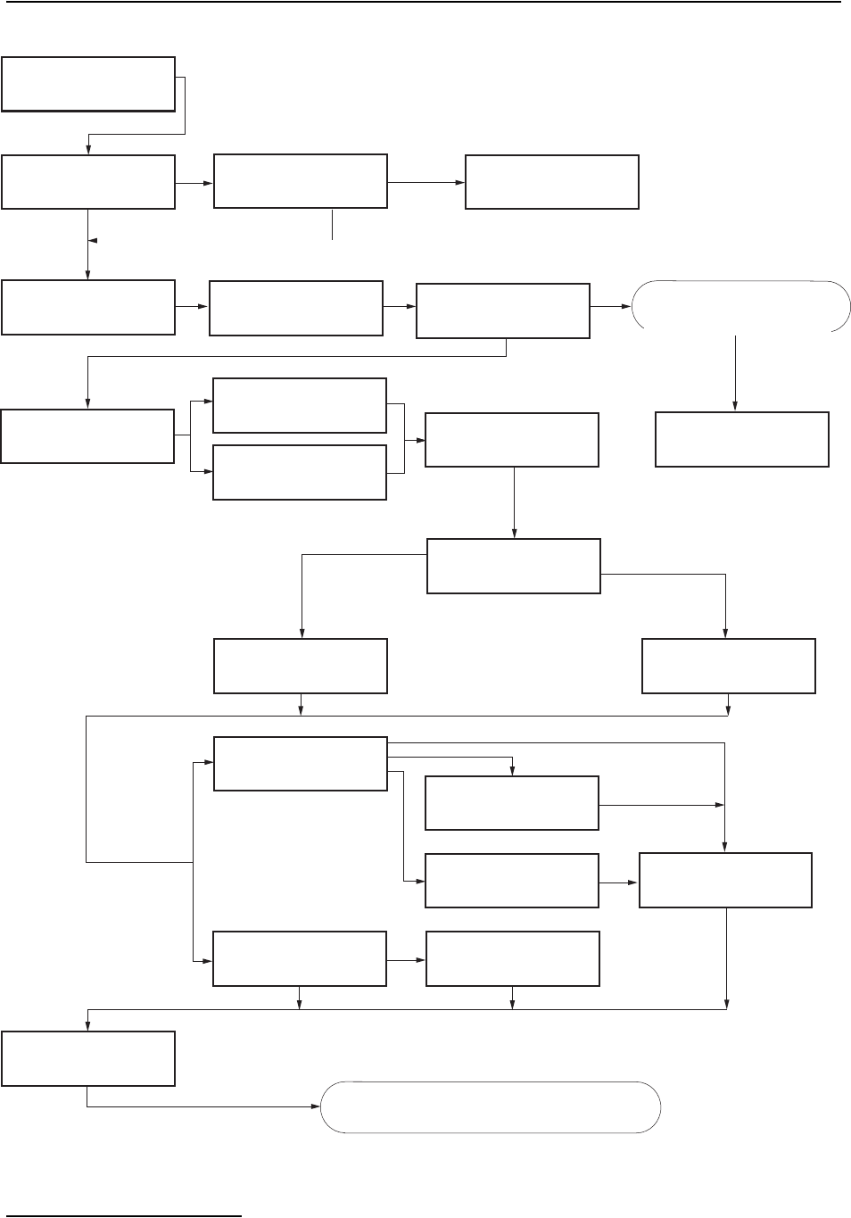
6712FR Refrigerated Sampler
Appendix A Menu Flowcharts
A-2
Figure A-2 Standard Programming: Programming Screens
RUN
PROGRAM
VIEW REPORT
OTHER FUNCTIONS
SITE DESCRIPTION:
"FACTORY"
CHANGE?
YES NO
SITE: __________
ABCDEFGHIJKLMNOPQRST
UVWXYZ -&"0123456789
BACK-UP DONE
NUMBER OF BOTTLES:
1 2 4 8 12 24
BOTTLE VOLUME IS
_____ ml (300-30000)
SUCTION LINE LENGTH
IS __ ft
(3-99)
TIME PACED
FLOW PACED
FLOW BETWEEN
SAMPLE EVENTS
(0.001-99999)
SAMPLE VOLUME:
____ ml (10-max)
YES
NO
DONE
SAVE CHANGES?
YES NO
If
STOP key
pressed.
TIME BETWEEN
SAMPLE EVENTS
__ HOURS, __ MINUTES
TAKE ___ SAMPLES
(1-999)
RUN CONTINUOUSLY?
YES NO
SEQUENTIAL
BOTTLES/SAMPLE
SAMPLES/BOTTLE
___ BOTTLES PER
SAMPLE EVENT (1-max)
___ SAMPLES PER
BOTTLE (1-max)
1 bottle
No
Ye s
Multi-bottle
BOTTLE VOLUME IS
_____ lit (0.3-100.0)
(if 1, 2, 4, or 8 bottles)
(if 12 or 24 bottles)
SELECT UNITS FOR
FLOW RATE:
cfs gps gpm Mgd
lps m3s m3h m3d
SELECT UNITS FOR
FLOW VOLUME:
cf gal Mgal
m3 lit
PROGRAM MODULE?
YES NO
If applicable
NEW MODULE SETUP--
DOWNLOAD DATA NOW
OR LOSE ALL DATA!
DONE
If applicable
YES
0.075 Mgal
DO YOU WANT TO
RUN CONTINUOUSLY?
YES NO
See Figure A-3: Standard and Extended
Programming: Start Times.
Programming screens for a
700 Series module. Refer to
Module’s manual.
Programming screens shown are for a 730 Bubbler
Flow Module. Screens for other modules may vary.
6712FR Refrigerated Sampler
Appendix A Menu Flowcharts
A-3
Figure A-3 Standard and Extended Programming: Start Times
NO DELAY TO START
DELAYED START
CLOCK TIME
WAIT FOR PHONE CALL
FIRST SAMPLE
AFTER A
___ MINUTE DELAY
(1-999)
SELECT DAYS:
SU MO TU WE TH FR SA
DONE
AT LEAST ONE DAY
MUST BE SELECTED!
FIRST VALID DAY
IS __-___
FIRST SAMPLE AT:
HH:MM
See Note D.
See Notes B & C.
PROGRAMMING COMPLETE
RUN THIS PROGRAM
NOW?
YES NO
RUN
PROGRAM
VIEW REPORT
OTHER FUNCTIONS
START "EXTENDED 1"
AFTER A
___ MINUTE DELAY
(1-999)
START FLOW COUNT
AFTER A
___ MINUTE DELAY
(1-999)
RUN "EXTENDED 1"
PROGRAM
VIEW REPORT
OTHER FUNCTIONS
NO
START FLOW COUNT AT
HH:MM
YES
See Note E.
E. Main menu for
extended
programming.
B. Appears for standard
flow-paced programs.
C. Appears for extended
programs.
D. Appears for standard
flow-paced programs.
Notes
(Extended Programming Only)
DONE
Continued from Figure A-2.
See Run Time Screens on page A-4.
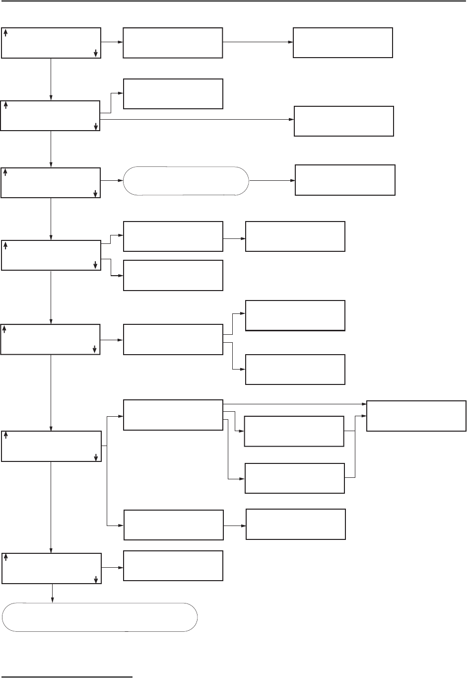
6712FR Refrigerated Sampler
Appendix A Menu Flowcharts
A-4
Figure A-4 Standard Programming: Quick View; Programming Screens
SITE DESCRIPTION:
"FACTORY "
SITE: __________
ABCDEFGHIJKLMNOPQRST
UVWXYZ -&"0123456789
BACK-UP DONE
NUMBER OF BOTTLES:
1 2 4 8 12 24
BOTTLE VOLUME IS
_____ ml (300-30000)
SUCTION LINE LENGTH
IS __ ft
(3-99)
SAVE CHANGES?
YES NO
TIME PACED
FLOW PACED
FLOW BETWEEN
SAMPLE EVENTS
0.075 Mgal
(0.001 - 99999)
TIME BETWEEN
SAMPLE EVENTS
__ HOURS, __ MINUTES
__, _____ml BOTTLES
__ ft SUCTION LINE
PACING:
TIME, EVERY
__ HOURS, __ MINUTES
If
STOP key
pressed.
TAKE ___ SAMPLES
(1-max)
RUN CONTINUOUSLY?
YES NO
__ SAMPLES PER
BOTTLE (1-max)
200 ml SAMPLES
DISTRIBUTION:
BOTTLES/SAMPLE
RUN CONTINUOUSLY
__ BOTTLES PER
SAMPLE EVENT (1-max)
SEQUENTIAL
BOTTLES/SAMPLE
SAMPLES/BOTTLE
Multi-Bottle
1 Bottle
No
SELECT UNITS FOR
FLOW RATE:
cfs gps gpm Mgd
lps m3s m3h m3d
SELECT UNITS FOR
FLOW VOLUME:
cf gal Mgal
m3 lit
BUBBLER MODULE
WEIR
90
V-NOTCH
If applicable
UNITS SELECTED
FLOW RATE: cfs
FLOW VOLUME: Mgal
If applicable
NEW MODULE SETUP--
DOWNLOAD DATA NOW
OR LOSE ALL DATA!
DONE
If applicable
MUST BE SELECTED!
SAMPLE VOLUME:
___ ml (10-max)
DO YOU WANT TO
RUN CONTINUOUSLY?
YES NO
Continued in Figure A-5.
Units Selected screens are for a 730 Bubbler Flow
Module. Screens for other modules may vary.
Programming screens for
a 730 Series Module.
Refer to Module’s manual.
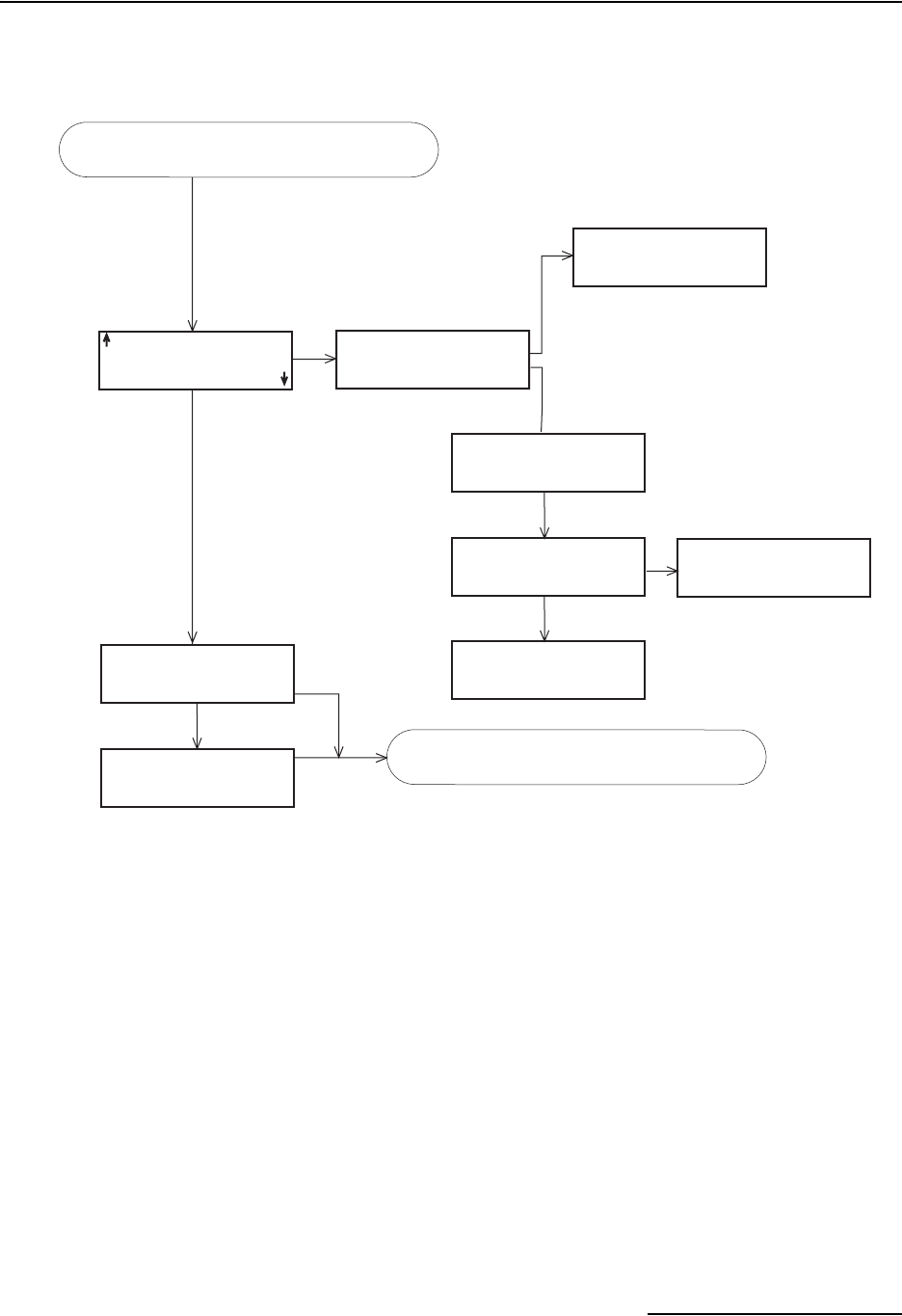
6712FR Refrigerated Sampler
Appendix A Menu Flowcharts
A-5
Figure A-5 Standard Programming: Quick View; Start Times
NO DELAY TO START
NO DELAY TO START
DELAYED START
CLOCK
WAIT FOR PHONE CALL
TIME
FIRST SAMPLE
AFTER A
___ MINUTE DELAY
(1-999)
SELECT DAY(S):
SU MO TU WE TH FR SA
DONE
FIRST SAMPLE: HH:MM
MO TH
FIRST SAMPLE AT:
HH:MM
PROGRAMMING COMPLETE
RUN THIS PROGRAM
NOW?
YES NO
RUN
PROGRAM
VIEW REPORT
OTHER FUNCTIONS
NO
YES
AT LEAST ONE DAY
MUST BE SELECTED!
DONE
If applicable
See Run Time Screens on page -10.
Continued from Figure A-4.
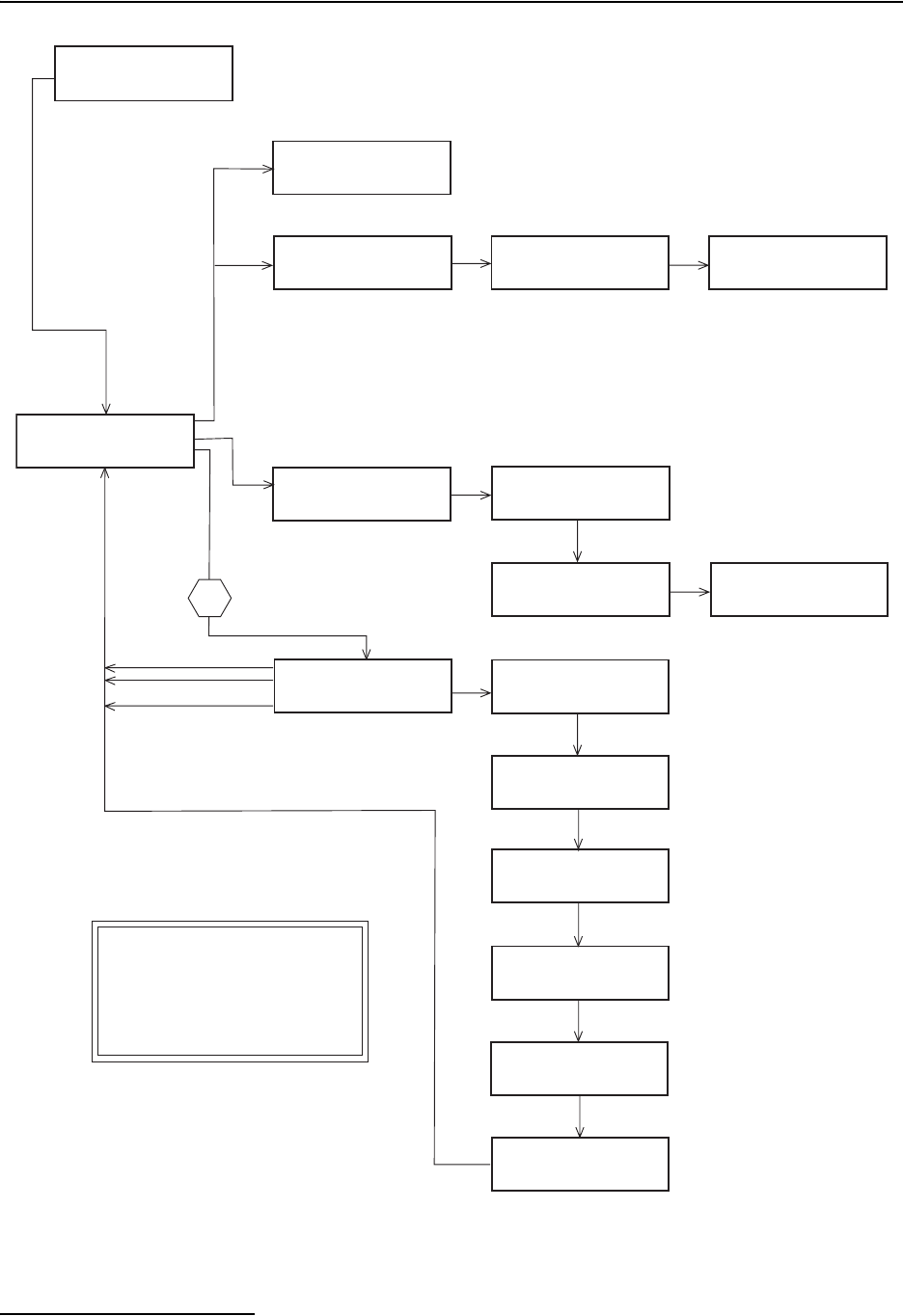
6712FR Refrigerated Sampler
Appendix A Menu Flowcharts
A-6
Figure A-6 View Report
RUN
PROGRAM
VIEW REPORT
OTHER FUNCTIONS
VIEW DATA
SYSTEM IDs
CONFIGURE REPORT
SELECT DATA TO VIEW:
MODULE FR-TEMP
RAIN SDI-12
SAMPLING REPORT
VIEW:
DAILY SUMMARY
CURRENT READINGS
pH MODULE
VIEW:
pH DATA
TEMPERATURE DATA
SAMPLER
6712 ID:1234567890
HARDWARE: B0
SOFTWARE: 1.00
SOFTWARE OPTIONS:
NONE
SAMPLINK REPORT
FLOWLINK REPORT
CUSTOM REPORT
ALL REPORTS
REPORTS FOR SAMPLER:
PROGRAM SETTINGS
SAMPLING RESULTS
BOTH NONE
REPORTS FOR MODULE:
DAILY SUMMARY
COMBINED RESULTS
BOTH NONE
REPORTS FOR RAIN:
DAILY SUMMARY
COMBINED RESULTS
BOTH NONE
DO YOU WANT
COMBINED RESULTS
FOR SDI-12 DATA?
YES NO
INCLUDE DETAIL DATA
FOR FLOWLINK AND
TEXTLINK PROGRAMS?
YES NO
REPORTS FOR FR-TEMP:
DAILY SUMMARY
COMBINED RESULTS
BOTH NONE
NO DATA
TO DISPLAY
ULTRASONIC MODULE:
0710 ID:1234567890
HARDWARE: A1
SOFTWARE: 1.00
When applicable
SDI-12 SONDE
SOFTWARE:
When applicable
When applicable
When applicable
When applicable
When applicable
Valid Options Will Be Shown; Screens Will Vary Depending on Devices Attached
No valid options
Note A:
Menu access can be controlled with the optional
Program Lock. See Note 8.
Note B:
1108 - Program Lock
Note A
Note B
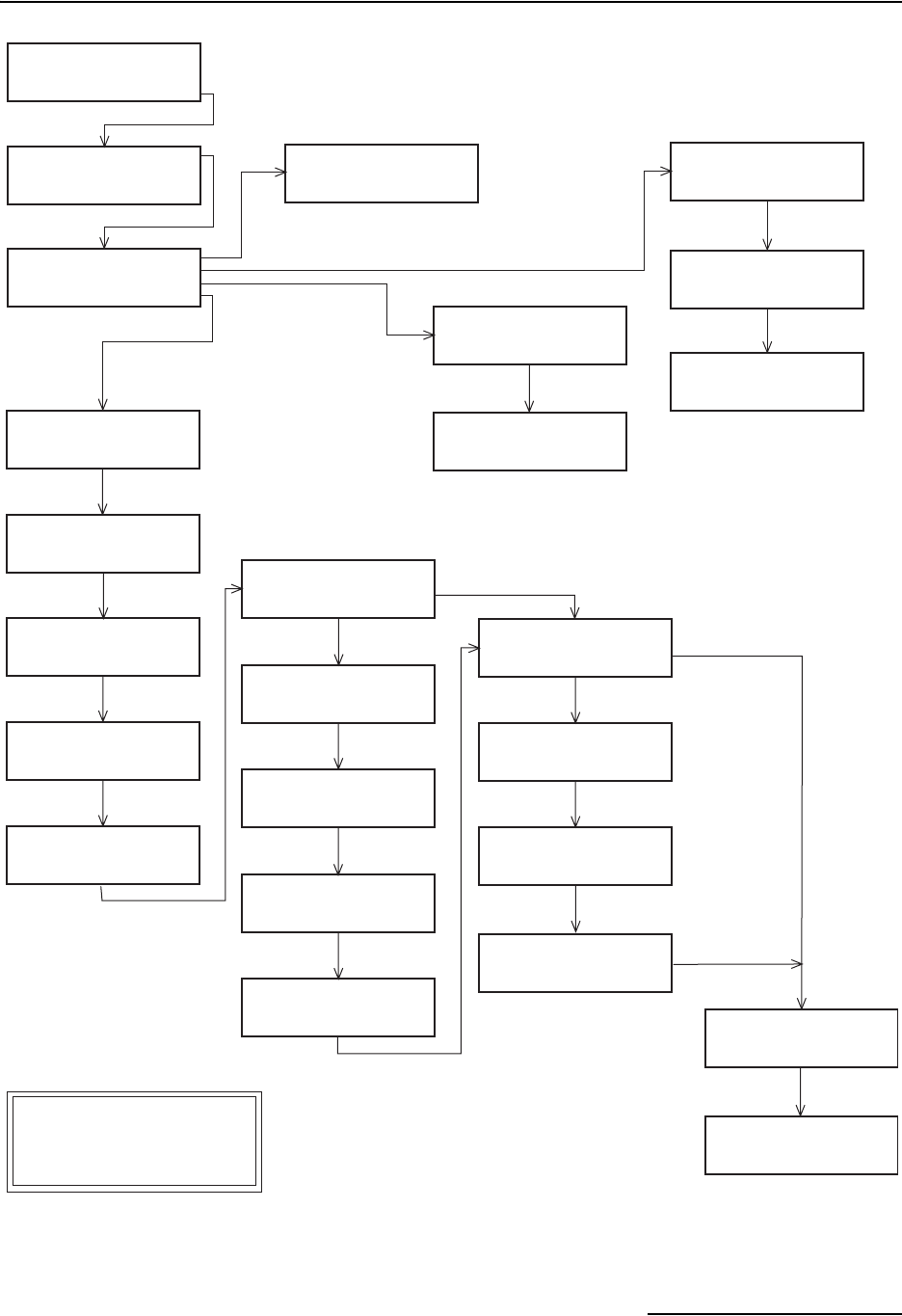
6712FR Refrigerated Sampler
Appendix A Menu Flowcharts
A-7
Figure A-7 Maintenance Screens
RUN
PROGRAM
VIEW REPORT
OTHER FUNCTIONS
MAINTENANCE
MANUAL FUNCTIONS
PROGRAMMING STYLE
SET CLOCK
PUMP TUBE ALARM
INTERNAL BATTERY
DIAGNOSTICS
ENTER TIME AND DATE:
HH:MM DD-MON-YY
__:__ __-__-__
________ PUMP COUNTS,
WARNING AT _______.
______ PUMP COUNTS,
RESET PUMP COUNTER?
YES NO
WARNING AT __00000
PUMP COUNTS
(1-99)00000
REPLACE INTERNAL
BATTERY BEFORE
__-__-__
RE-INITIALIZE?
YES NO
DID YOU REPLACE THE
INTERNAL BATTERY?
YES NO
PLEASE WAIT!
. . . TESTING 'RAM'
'RAM' PASSED TEST
PLEASE WAIT!
. . .TESTING 'ROM'
'ROM' PASSED TEST
ABCDEFGHIJKLMNOPQRST
ABCDEFGHIJKLMNOPQRST
ABCDEFGHIJKLMNOPQRST
ABCDEFGHIJKLMNOPQRST
TEST PUMP?
YES NO
TEST DISTRIBUTOR?
YES NO
DEFAULT SETTINGS?. . .
ARE YOU SURE?
YES NO
PUMPING . . .
PUMPING . . .
ON/OFF RATIO= _.__
PURGING . . .
FINDING ARM FLEXURE
NOW AT BOTTLE __
PURGING . . .
ON/OFF RATIO= _.__
NO
YES
NO
YES
YES
A. The standard programming
maintenance screen is shown.
Extended programming has
SOFTWARE and HARDWARE options.
Note
See Note A.
DISTRIBUTOR SYSTEM
ARM FLEXURE=__
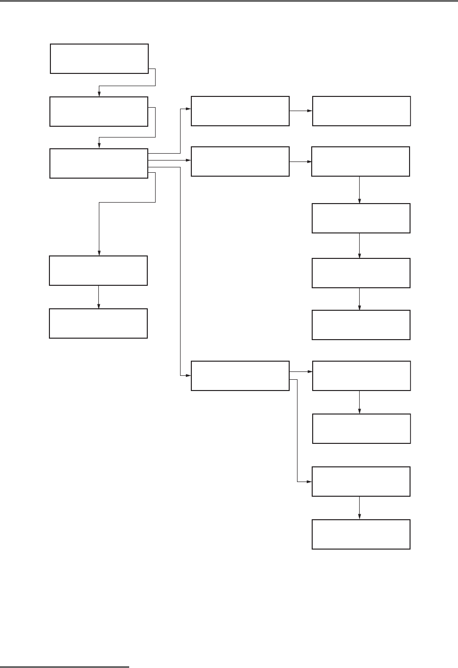
6712FR Refrigerated Sampler
Appendix A Menu Flowcharts
A-8
Figure A-8 Manual Functions Screens
RUN
PROGRAM
VIEW REPORT
OTHER FUNCTIONS
MAINTENANCE
MANUAL FUNCTIONS
PROGRAMMING STYLE
GRAB SAMPLE
CALIBRATE VOLUME
OPERATE PUMP
MOVE DISTRIBUTOR
SAMPLE VOLUME:
____ml (10-9990)
SAMPLE VOLUME:
____ml (100-9990)
GRAB SAMPLE
PRESS ↵ WHEN READY!
CALIBRATE VOLUME
PRESS ↵ WHEN READY!
VOLUME DELIVERED:
_____ ml
_____ ml!
ARE YOU SURE?
YES NO
SELECT DIRECTION:
PUMP FORWARD
PUMP REVERSE
GO TO BOTTLE __
(1-max)
NOW AT BOTTLE __
PURGING...
PRESS THE RED 'STOP'
KEY WHEN DONE!
PURGED _____ COUNTS
PUMPING...
PRESS THE RED 'STOP'
KEY WHEN DONE!
PUMPED _____ COUNTS
COMPACT PORTABLE
STANDARD PORTABLE
REFRIGERATOR
if not known
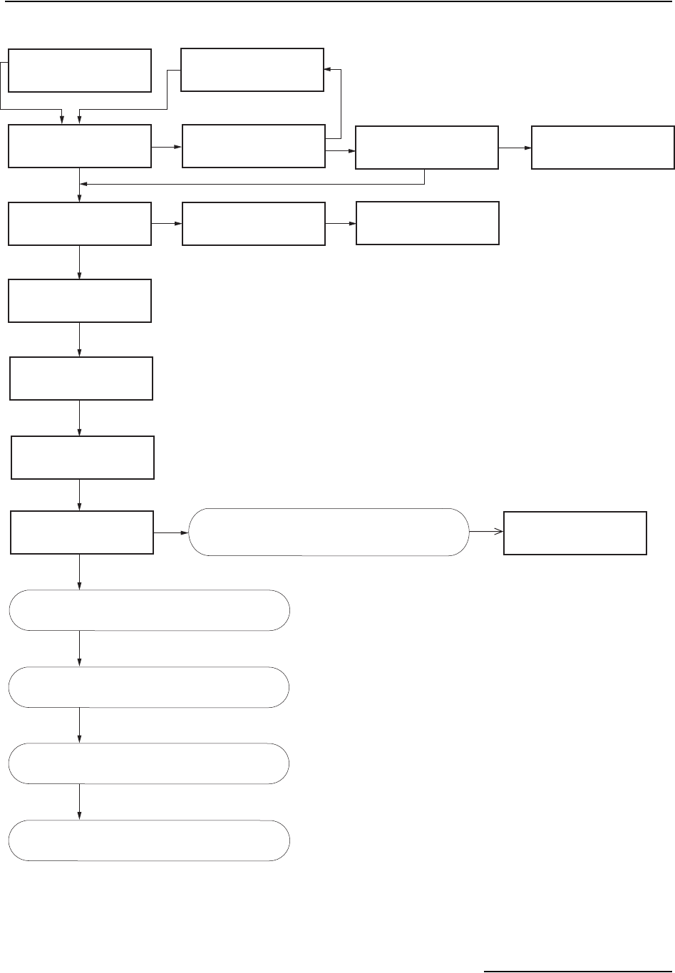
6712FR Refrigerated Sampler
Appendix A Menu Flowcharts
A-9
Figure A-9 Extended Programming: Programming Screens
RUN "EXTENDED 1"
PROGRAM
VIEW REPORT
OTHER FUNCTIONS
YES
If
STOP key
pressed.
If
STOP key
pressed.
PROGRAM NAME:
"ISCO 6712 "
CHANGE?
YES NO
SELECT NEW PROGRAM
CHANGE PROGRAM NAME
SITE DESCRIPTION:
"FACTORY "
CHANGE?
YES NO
SITE: __________
ABCDEFGHIJKLMNOPQRST
UVWXYZ -&"0123456789
BACK-UP DONE
NAME: __________
ABCDEFGHIJKLMNOPQRST
UVWXYZ -&"0123456789
BACK-UP DONE
SAVE CHANGES?
YES NO
SAVE CHANGES?
YES NO
"EXTENDED 1"
"EXTENDED 2"
"EXTENDED 3"
"EXTENDED 4"
NO
NO
YES
PROGRAM MODULE?
YES NO
SELECT UNITS FOR
LENGTH:
ft m
NEW MODULE SETUP--
DOWNLOAD DATA NOW
OR LOSE ALL DATA!
DONE
If applicable
SELECT UNITS FOR
FLOW RATE:
cfs gps gpm Mgd
lps m3s m3h m3d
SELECT UNITS FOR
FLOW VOLUME:
cf gal Mgal
m3 lit
YES
See Figure A-10.
See Figure A-11.
See Figure A-12.
See Figure A-6.
Programming screens for a 700 Series Module.
Refer to the Module’s manual.
Units Selected screens are for a 730 Bubbler Flow
Module. Screens for other modules may vary.
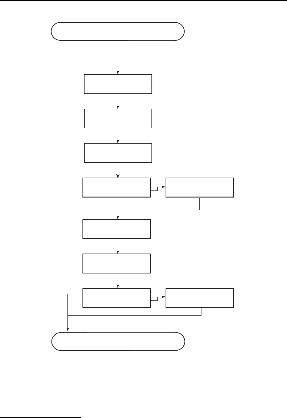
6712FR Refrigerated Sampler
Appendix A Menu Flowcharts
A-10
Figure A-10 Extended Programming: Equipment Setup
NUMBER OF BOTTLES:
1 2 4 8 12 24
BOTTLE VOLUME IS
_____ ml (300-30000)
SUCTION LINE LENGTH
IS __ ft
(3-99)
AUTO SUCTION HEAD
ENTER HEAD
_ RINSE CYCLES
(0-3)
RETRY UP TO _ TIMES
WHEN SAMPLING
(0-3)
ONE-PART PROGRAM
TWO-PART PROGRAM
__ BOTTLES AVAILABLE
ASSIGN BOTTLES
1 THRU __ TO
PART 'A' (1-max)
SUCTION HEAD OF
__ ft
(min-max)
See Figure A-11.
Continued from Figure A-9.
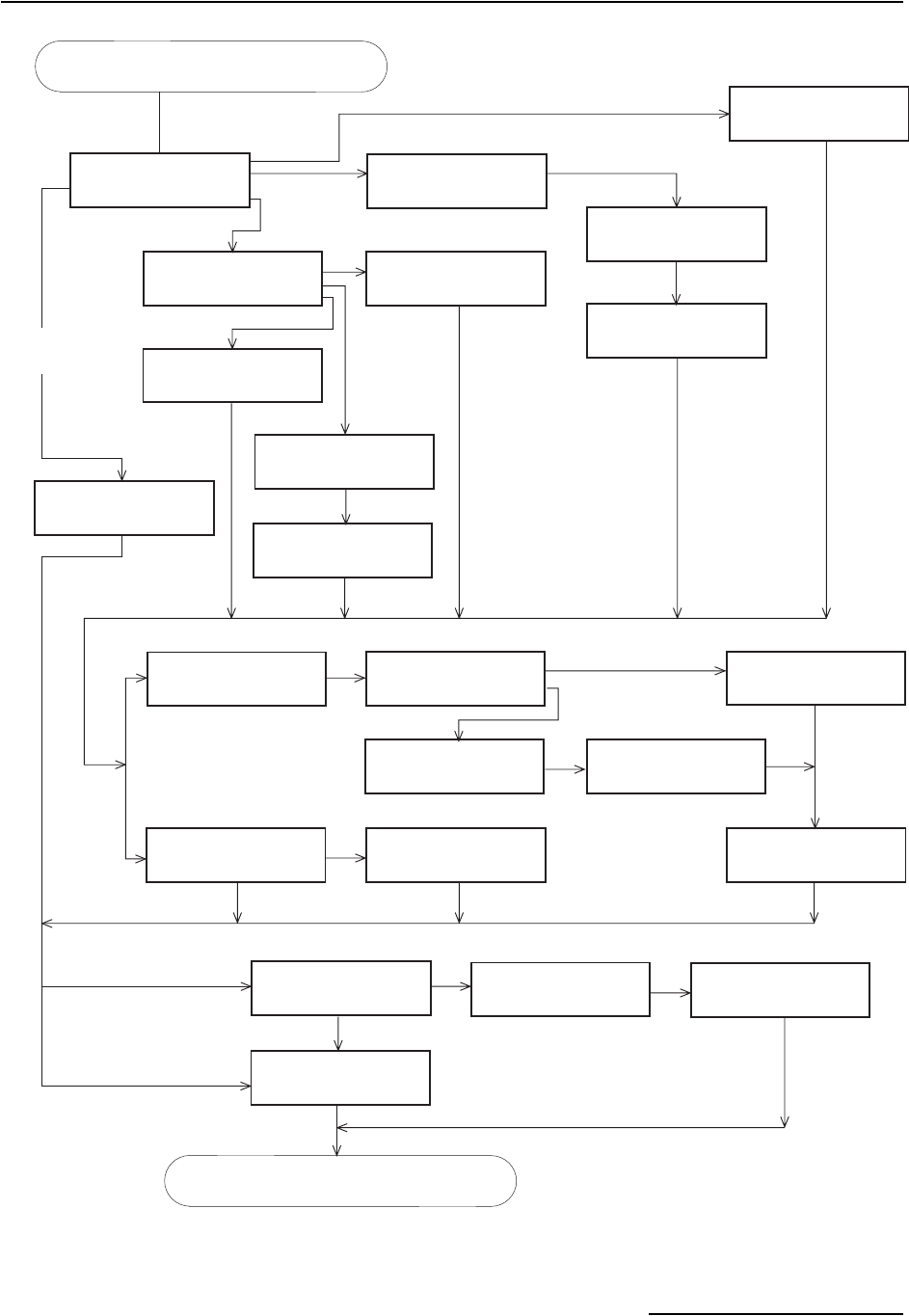
6712FR Refrigerated Sampler
Appendix A Menu Flowcharts
A-11
Figure A-11 Extended Programming: Pacing and Distribution
UNIFORM TIME PACED
FLOW PACED
EVENT PACED
NONUNIFORM TIME
NONUNIFORM TIME:
CLOCK TIMES
INTERVALS IN MINUTES
RANDOM INTERVALS
FLOW BETWEEN
SAMPLE EVENTS:
____ PULSES (1-9999)
PACED BY:
FLOW PULSES
FLOW MODULE VOLUME
QUANTITY AT INTERVAL
1. __ AT ___ MIN
2. __ AT ___ MIN
3. __ AT ___ MIN
FIRST SAMPLE AT
START TIME,
THEN ...
SAMPLE AT START?
YES NO
PROGRAM RUN TIME:
__ HOURS, __ MINUTES
TIME BETWEEN
SAMPLE EVENTS:
__ HOURS, __ MINUTES
TAKE SAMPLES AT:
1. START TIME
2. HH:MM
3. HH:MM
TAKE ___ SAMPLES
(1-999)
RUN CONTINUOUSLY?
YES NO
RUN CONTINUOUSLY?
YES NO
DO YOU WANT TO
RUN CONTINUOUSLY?
YES NO
__ BOTTLES PER
SAMPLE EVENT (1-max)
SWITCH BOTTLES EVERY
___ SAMPLES (1-max)
SWITCH BOTTLES ON:
NUMBER OF SAMPLES
TIME
SWITCH BOTTLES EVERY
__ HOURS, __ MINUTES
FIRST SWITCH TIME
AT __:__
1 bottle
No
Multi-bottle
DO YOU WANT
SAMPLE VOLUMES
DEPENDENT ON FLOW?
YES NO
FLOW PULSES
FLOW MODULE VOLUME
SAMPLE VOLUME:
___ ml (10-max)
SAMPLE VOLUME:
10 ML FOR EVERY
___ PULSES
Ye s
Ye s
Uniform Time Paced Only
All other pacing
No
See Figure A-12:
Event Conditions
Continued from Figure A-10.
See Figure A-13.
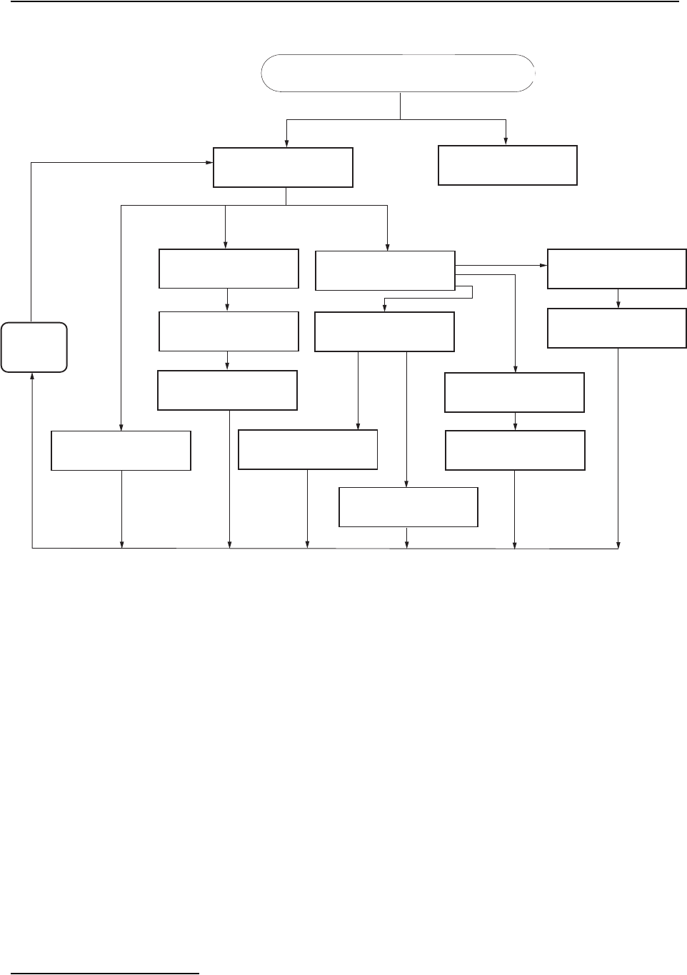
6712FR Refrigerated Sampler
Appendix A Menu Flowcharts
A-12
Figure A-12 Extended Programming: Event Conditions
ENABLED WHEN:
I/O ENABLE IS HIGH
I/O ENABLE IS LOW
EVENT:
RAIN LEVEL FLOW
pHx TEMPx CONDx
TDSx DOx NONE
ENABLED WHEN:
ABOVE SET POINT
BELOW SET POINT
"RAIN" SET POINT:
__.__ INCHES PER
__HOURS, __MINUTES
NO EVENT PARAMETERS
CURRENTLY AVAILABLE
"LEVEL" RISES
_._ ft.
__HOURS, __MINUTES
"LEVEL" RANGE:
LOWER:_.__ft
UPPER:_.__ft
(0.001-30.000)
"LEVEL" SET POINT:
_.__ft
(0.001-30.000)
ENABLED WHEN:
INSIDE RANGE
OUTSIDE RANGE
ENABLED WHEN:
ABOVE SET POINT
BELOW SET POINT
"LEVEL" CONDITION:
SET POINT
RANGE
RATE OF CHANGE
RESET RAIN HISTORY?
YES NO
Repeat until
conditions
are set or
until DONE
All valid event options will be shown.
I/O RAIN OTHER OPTIONS
_._ ft.
__HOURS, __MINUTES
CONDITION IS TRUE
WHEN "LEVEL"
RISES FALLS
"LEVEL" FALLS
Continued from Figure A-12.
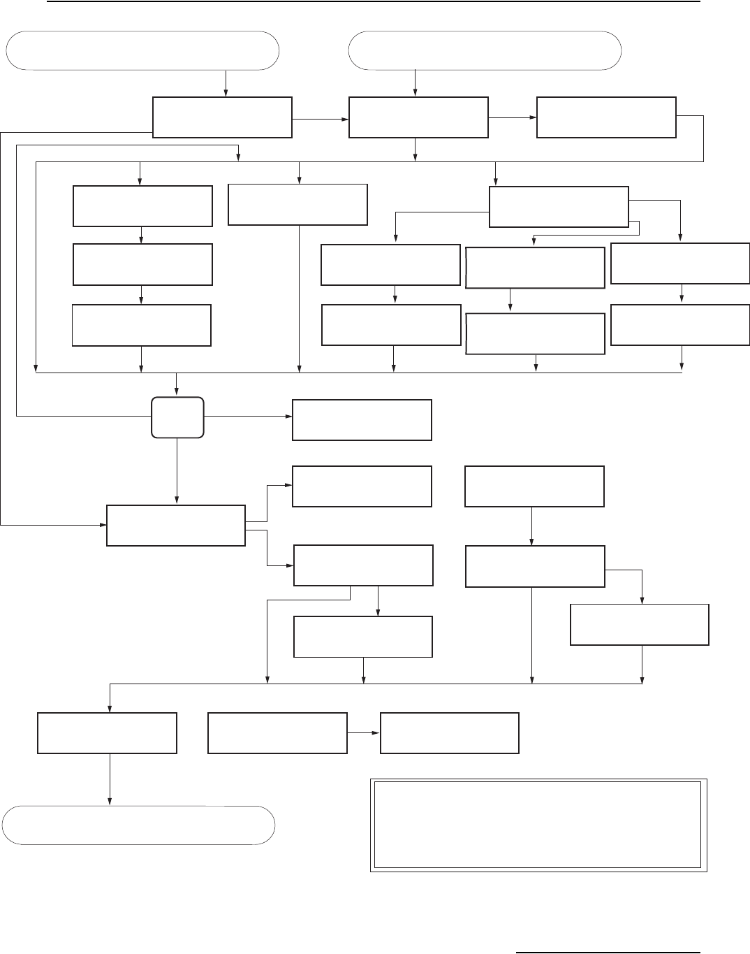
6712FR Refrigerated Sampler
Appendix A Menu Flowcharts
A-13
Figure A-13 Extended Programming: Programmed Sampler Enable
SAMPLE AT ENABLE?
YES NO
SAMPLE AT ENABLE?
YES NO
START OF SAMPLING
AFTER A
___ MINUTE DELAY
(0-999)
RESET SAMPLE
INTERVAL AT ENABLE?
YES NO
ONCE ENABLED,
STAY ENABLED?
YES NO
CONTINUE COUNTDOWN
WHILE DISABLED?
YES NO
PAUSE RESUME
1.HH:MM DD HH:MM DD
2.HH:MM DD HH:MM DD
CLEAR DONE
PAUSE & RESUMES
MUST BE ENTERED
IN PAIRS!
SAMPLE AT RESUME?
YES NO
SAMPLE AT DISABLE?
YES NO
ENABLE:
I/O RAIN LEVEL
FLOW TEMPx CONDx
TDSx DOx NONE
ENABLED WHEN:
ABOVE SET POINT
BELOW SET POINT
"RAIN" SET POINT:
__.__ INCHES PER
__HOURS, __MINUTES
ENABLE: RAIN
AND OR DONE
ENABLE: RAIN AND
I/O LEVEL FLOW
TEMPx CONDx TDSx
DOx DONE
"LEVEL" CONDITION:
SET POINT
RANGE
RATE OF CHANGE
"LEVEL" RANGE:
LOWER:_.__ft
UPPER:_.__ft
(0.001-30.000)
"LEVEL" SET POINT:
_.__ft
(0.001-30.000)
ENABLED WHEN:
INSIDE RANGE
OUTSIDE RANGE
ENABLED WHEN:
ABOVE SET POINT
BELOW SET POINT
ENABLED WHEN:
I/O ENABLE IS HIGH
I/O ENABLE IS LOW
RESET RAIN HISTORY?
YES NO
REPEAT
FOR
SECOND
TYPE
I/O All except I/O, Rain, and 'A' Done
'A' Done and I/O are not options for I/O Conditions
RAIN
'A' DONE
All except
NONE
DONE
NONE
AND
or OR
See Note A. See Note A.
See Note B
Notes
If applicable If applicable
No
No
No
If applicable
Ye s
Ye s
Repeat
Ye s
A. All valid enable options will be shown. Enable options may include:
LEVEL, FLOW, pH, TEMP, PERCENT, VEL, RAIN, I/O, 'A'DONE
FR-TEMP, TEMPx, CONDx, SP_COx, TDSx, SALx, DOx,
pHx, ORPx, LEVELx, NH4x, NH3x, NO3x, TURBx, Clx,
FLOWx
B. YES = Latched or Stay Enabled
NO = Repeatable Enable
CHECK ENABLE EVERY
0.5 1 2 5
10 15 30
MINUTES
"LEVEL" RISES
_.__ft
__HOURS, __MINUTES
CONDITION IS TRUE
WHEN "LEVEL"
RISES FALLS
Continued from Figure A-11. Continued from Figure A-21.
See Figure A-5.
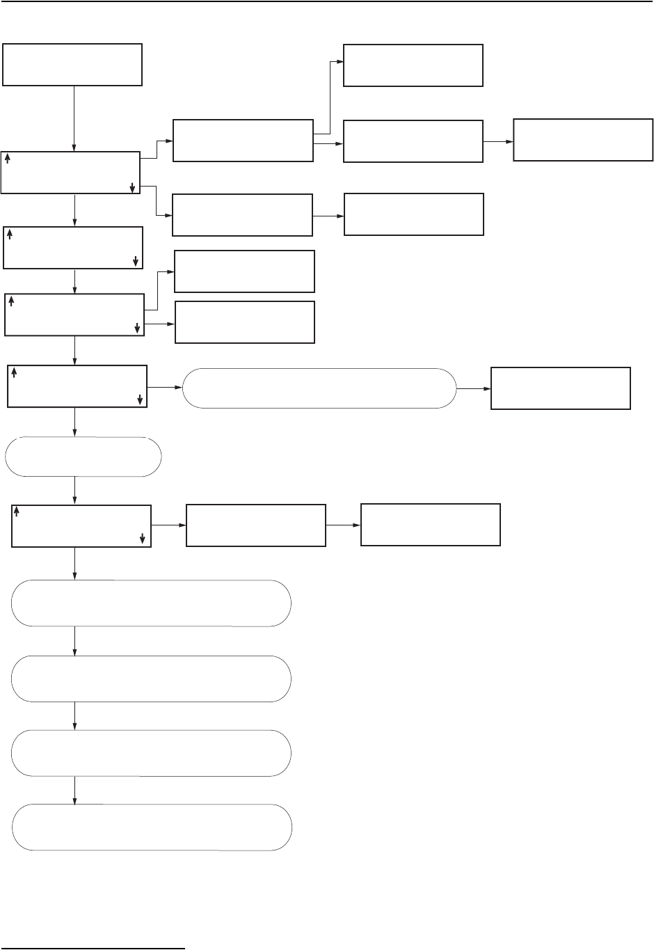
6712FR Refrigerated Sampler
Appendix A Menu Flowcharts
A-14
Figure A-14 Extended Programming: Quick View; Programming Screens
RUN "EXTENDED 1"
PROGRAM
VIEW REPORT
OTHER FUNCTIONS
"EXTENDED 1"
"EXTENDED 2"
"EXTENDED 3"
"EXTENDED 4"
SELECT NEW PROGRAM
CHANGE PROGRAM NAME
NAME: __________
ABCDEFGHIJKLMNOPQRST
UVWXYZ -&"0123456789
BACK-UP DONE
NAME: __________
ABCDEFGHIJKLMNOPQRST
UVWXYZ -&"0123456789
BACK-UP DONE
SAVE CHANGES?
YES NO
PROGRAM NAME:
"EXTENDED 1"
SITE DESCRIPTIONS:
"FACTORY "
SAVE CHANGES?
YES NO
__ MINUTE
DATA INTERVAL
UNITS SELECTED:
LENGTH: ft
UNITS SELECTED:
FLOWRATE: cfs
BUBBLER MODULE:
WEIR
90o
V-NOTCH
FLOW VOLUME: Mgal
If applicable
SELECT UNITS FOR
FLOW RATE:
cfs gps gpm Mgd
lps m3s m3h m3d
FLOW VOLUME:
cf gal Mgal
m3 lit
SELECT UNITS FOR
NEW MODULE SETUP--
DOWNLOAD DATA NOW
OR LOSE ALL DATA!
DONE
If applicable
DATA STORAGE
INTERVAL IN MINUTES:
1 2 5
10 15 30
INTERVAL CHANGED--
DOWNLOAD DATA NOW
OR LOSE ALL DATA!
DONE
If applicable
See Figure A-16
See Figure A-17.
See Figure A-5.
See Figure A-15.
Programming screens for a 700 Series
Modules. Refer to the Module’s manual.
May ask for level, offset, etc.
Series of screens will vary,
depending upon module.
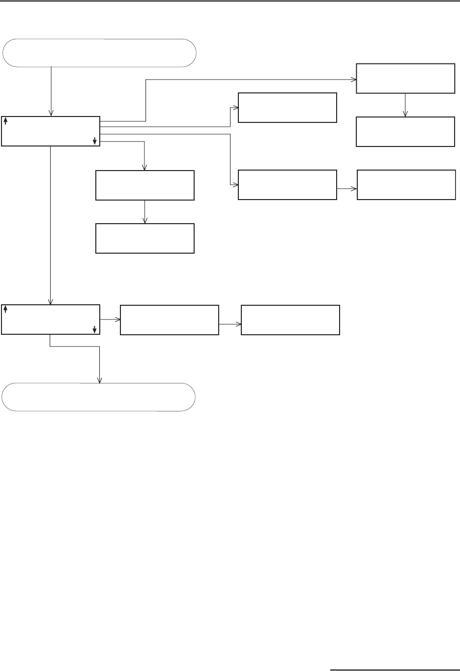
6712FR Refrigerated Sampler
Appendix A Menu Flowcharts
A-15
Figure A-15 Extended Programming: Quick View; Equipment Set-Up
__,____ ml BOTTLES
__ ft SUCTION LINE
AUTO SUCTION HEAD
_ RINSES, _RETRIES
NUMBER OF BOTTLES:
1 2 4 8 12 24
BOTTLE VOLUME IS
_____ ml (300-30000)
SUCTION LINE LENGTH
IS __ ft
(3-99)
AUTO SUCTION HEAD
ENTER HEAD
SUCTION HEAD OF
IS __ ft
(min-max)
_ RINSE CYCLES
(0-3)
RETRY UP TO _ TIMES
WHEN SAMPLING
(0-3)
ONE-PART PROGRAM
TWO-PART PROGRAM
__ BOTTLES AVAILABLE
ASSIGN BOTTLES
1 THRU __ TO
PART 'A' (1-max)
ONE PART PROGRAM
When Liquid Detector is on
See Figure A-16.
Continued from Figure A-14.
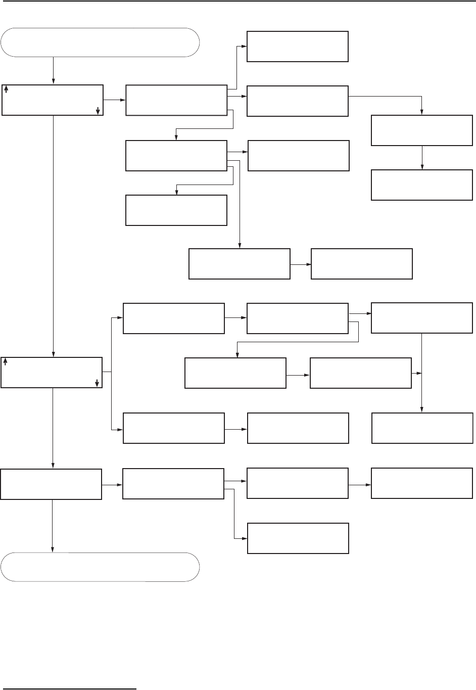
6712FR Refrigerated Sampler
Appendix A Menu Flowcharts
A-16
Figure A-16 Extended Programming: Quick View; Pacing and Distribution
PACING:
TIME, EVERY
__ HOURS, __ MINUTES
UNIFORM TIME PACED
FLOW PACED
EVENT PACED
NONUNIFORM TIME
NONUNIFORM TIME:
CLOCK TIMES
INTERVALS IN MINUTES
RANDOM INTERVALS
FLOW BETWEEN
SAMPLE EVENTS:
____ PULSES (1-9999)
PACED BY:
FLOW PULSES
FLOW MODULE VOLUME
QUANTITY AT INTERVAL
1. __ AT ___ MIN
2. __ AT ___ MIN
3. __ AT ___ MIN
FIRST SAMPLE AT
START TIME,
THEN ...
SAMPLE AT START?
YES NO
PROGRAM RUN TIME:
__ HOURS, __ MINUTES
TIME BETWEEN
SAMPLE EVENTS:
__ HOURS, __ MINUTES
TAKE SAMPLES AT:
1. START TIME
2. HH:MM
3. HH:MM
TAKE ___ SAMPLES
(1-999)
__ BOTTLES PER
SAMPLE EVENT (1-max)
SWITCH BOTTLES EVERY
___ SAMPLES (1-max)
SWITCH BOTTLES ON:
NUMBER OF SAMPLES
TIME
FIRST SWITCH TIME
AT __:__
SWITCH BOTTLES EVERY
__ HOURS, __ MINUTES
VOLUME
____ ml SAMPLES
DO YOU WANT
SAMPLE VOLUMES
DEPENDENT ON FLOW?
YES NO
SAMPLE VOLUME:
___ ml (10-max)
DISTRIBUTION:
__ BOTTLES/SAMPLE
___ SAMPLES/BOTTLE
RUN CONTINUOUSLY
1 bottle
Ye s
Uniform Time Paced Only
No
No
Multi-bottle
SAMPLE VOLUME:
10 ML FOR EVERY
___ PULSES (1-9999)
MINIMUM
SAMPLE VOLUME:
___ ml (10 - max)
DO YOU WANT TO
RUN CONTINUOUSLY?
YES NO
DO YOU WANT TO
RUN CONTINUOUSLY?
YES NO
Continued from Figure A-15.
See FigureA-17.
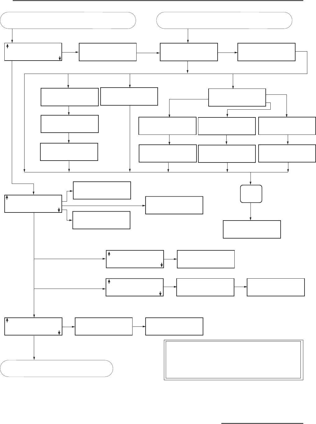
6712FR Refrigerated Sampler
Appendix A Menu Flowcharts
A-17
Figure A-17 Extended Programming: Quick View; Programmed Sampler Enable
'A' ENABLE:
RAIN>0.11"/1:00
AND
0.500<LEVEL<1.500
'A' ENABLE:
COUNTDOWN CONTINUES
WHILE DISABLED
SAMPLE AT ENABLE?
YES NO
START OF SAMPLING
AFTER A
___ MINUTE DELAY
(0-999)
RESET SAMPLE
INTERVAL AT ENABLE?
YES NO
ONCE ENABLED,
STAY ENABLED?
YES NO
CONTINUE COUNTDOWN
WHILE DISABLED?
YES NO
PAUSE RESUME
1.HH:MM DD HH:MM DD
2.HH:MM DD HH:MM DD
CLEAR DONE
SAMPLE AT RESUME?
YES NO
'A' ENABLE:
REPEATABLE ENABLE
SAMPLE AT DISABLE
NO SAMPLE AT ENABLE
'A' ENABLE:
__ MINUTE DELAY TO
START OF SAMPLING
'A' ENABLE:
_ PAUSE & RESUMES
NO SAMPLE AT RESUME
Latched Enable +
No Sample at Enable
NO
SAMPLE AT DISABLE?
YES NO
Repeatable Enable
Repeatable Enable
ENABLE:
I/O RAIN LEVEL
FLOW pH TEMP
COND D.O. NONE
ENABLED WHEN:
ABOVE SET POINT
BELOW SET POINT
"RAIN" SET POINT:
__.__ INCHES PER
__HOURS, __MINUTES
ENABLE: RAIN
AND OR DONE
ENABLE: RAIN AND
I/O LEVEL FLOW
pH TEMP COND D.O.
NONE
RESET RAIN HISTORY?
YES NO
REPEAT
FOR
SECOND
TYPE
I/O
RAIN'A' DONE
All except
NONE
DONE
AND
or OR
See Note A. See Note A.
See Note B.
If applicable
If applicable
All except I/O, Rain, and 'A' Done
Notes
A. All valid enable options will be shown. Enable options may include:
LEVEL, FLOW, pH, TEMP, PERCENT, VEL, RAIN, I/O, 'A'DONE
FR-TEMP, TEMPx, CONDx, SP_COx, TDSx, SALx, DOx,
pHx, ORPx, LEVELx, NH4x, NH3x, NO3x, TURBx, Clx,
FLOWx
B. YES = Latched or Stay Enabled
NO = Repeatable Enable
'A' Done and I/O are not options for I/O Conditions
CHECK ENABLE EVERY
0.5 1 2 5
10 15 30
MINUTES
"LEVEL" CONDITION:
SET POINT
RANGE
RATE OF CHANGE
"LEVEL" RANGE:
LOWER:_.__ft
UPPER:_.__ft
(0.001-30.000)
"LEVEL" SET POINT:
_.__ft
(0.001-30.000)
ENABLED WHEN:
INSIDE RANGE
OUTSIDE RANGE
ENABLED WHEN:
ABOVE SET POINT
BELOW SET POINT
ENABLED WHEN:
I/O ENABLE IS HIGH
I/O ENABLE IS LOW
"LEVEL" RISES:
_.__ft
__HOURS, __MINUTES
CONDITION IS TRUE
WHEN "LEVEL"
RISES FALLS
Continued from Figure A-16. Continued from Figure A-21.
See Figure A-5.
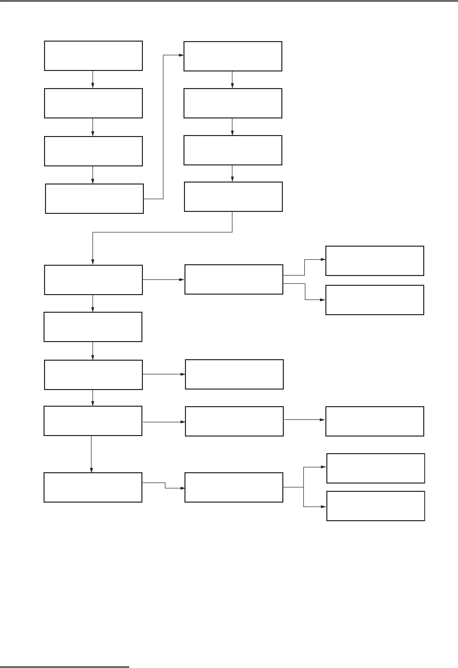
6712FR Refrigerated Sampler
Appendix A Menu Flowcharts
A-18
Figure A-18 Extended Programming: Normal View; Software Options
RUN "ISCO 6712 "
PROGRAM
VIEW REPORT
OTHER FUNCTIONS
USE LIQUID DETECTOR?
YES NO
MAINTENANCE
MANUAL FUNCTIONS
SOFTWARE OPTIONS
HARDWARE
DUAL SAMPLER MODE?
YES NO
BOTTLE FULL DETECT?
YES NO
BACKLIGHT ALWAYS OFF
TIMED BACKLIGHT
CONTINUOUS BACKLIGHT
EVENT MARK DURATION:
3 SECONDS
WHILE PUMPING
POST-SAMPLE PURGE:
___ COUNTS
(10-9999)
PORT SETTINGS:
9600n81 4800n81
2400n81 1200n81
SERIAL OUTPUT EVERY:
15 SEC 1 MIN
5 MIN 5 MIN
AT THE BEGINNING OF:
INITIAL PURGE
FORWARD PUMPING
DURING:
ENTIRE PUMP CYCLE
FORWARD PUMPING
MEASUREMENT INTERVAL
5 15 30 SECONDS
1 2 5 MINUTES
STORAGE INTERVAL
PROGRAMMING STYLE:
NORMAL
QUICK VIEW/CHANGE
EVENT MARK SENT FOR:
EVERY SAMPLE
COMPLETE SAMPLES
PRE-SAMPLE PURGE:
__ COUNTS
(10-9999)
POST-SAMPLE PURGE:
DEPENDENT ON HEAD
FIXED COUNT
PERIODIC
SERIAL OUTPUT?
YES NO
POWER ALWAYS ON
POWER ON/OFF TIMES
ALARM DIALOUTS ONLY
YES
If applicable
POWER ON OFF
1. _:_ _:_
2. _:_ _:_
CLEAR DONE
POWER ON/OFF TIMES
CANNOT SPAN
MORE THAN ONE DAY!
POWER ON/OFF TIMES
MUST BE ENTERED
IN PAIRS!
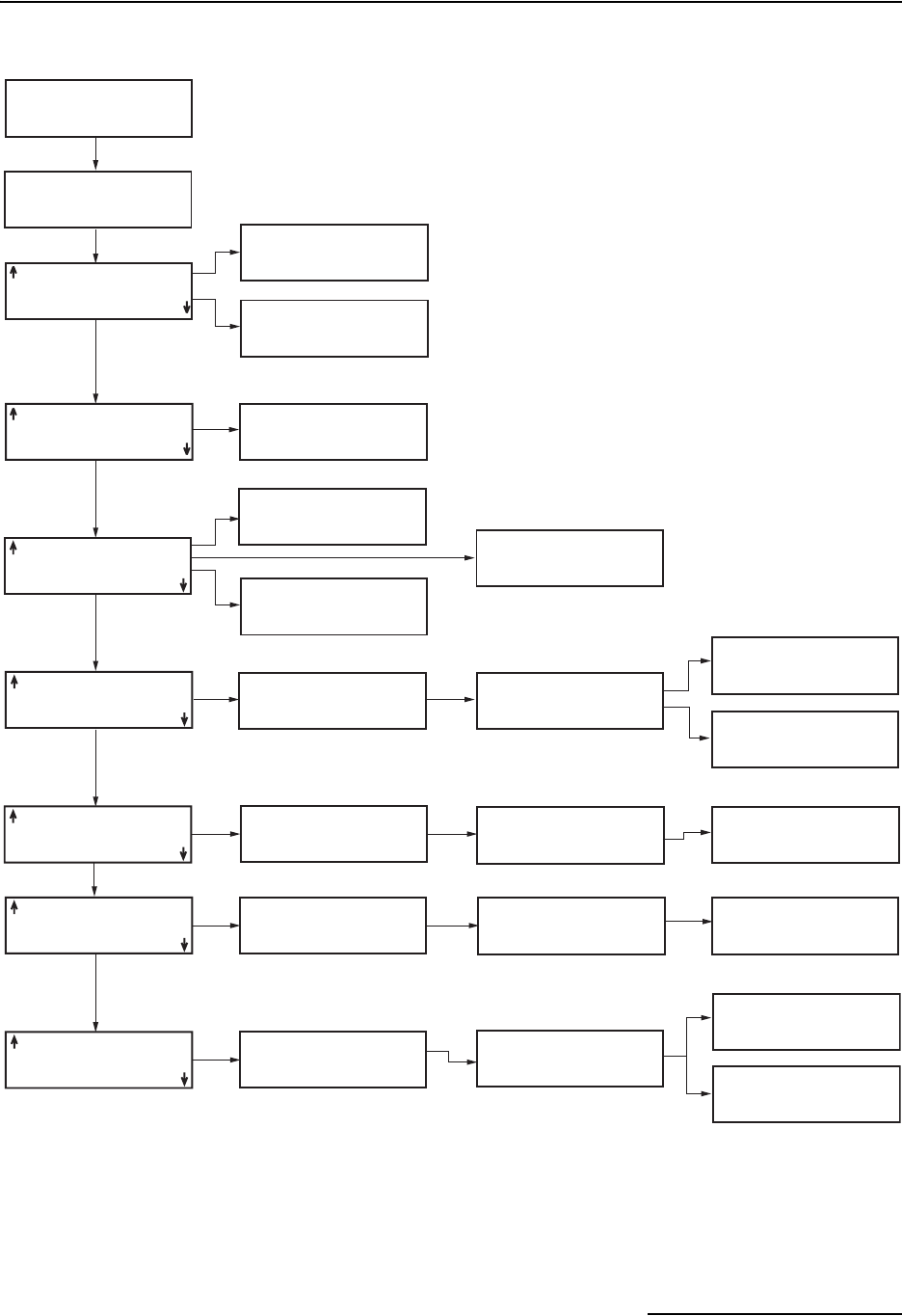
6712FR Refrigerated Sampler
Appendix A Menu Flowcharts
A-19
Figure A-19 Extended Programming: Quick View; Software Options
LIQUID DETECT ON
QUICK VIEW/CHANGE
DUAL SAMPLER ON
BTL FULL DECTECT OFF
TIMED BACKLIGHT
EVENT MARK SENT
WHILE
PUMPING FORWARD
PUMP COUNTS FOR
EACH PURGE CYCLE:
__ PRE-SAMPLE
__ POST-SAMPLE
SERIAL OUTPUT
EVERY __ MINUTES
INTERROGATOR
CONNECTOR
POWER ALWAYS ON
TAKE MEASUREMENTS
EVERY __ MINUTES
RUN "ISCO 6712 "
PROGRAM
VIEW REPORT
OTHER FUNCTIONS
USE LIQUID DETECTOR?
YES NO
MAINTENANCE
MANUAL FUNCTIONS
SOFTWARE OPTIONS
HARDWARE
DUAL SAMPLER MODE?
YES NO
BOTTLE FULL DETECT?
YES NO
BACKLIGHT ALWAYS OFF
TIMED BACKLIGHT
CONTINUOUS BACKLIGHT
PROGRAMMING STYLE:
NORMAL
QUICK VIEW/CHANGE
MEASUREMENT INTERVAL
5 15 30 SECONDS
1 2 5 MINUTES
STORAGE INTERVAL
EVENT MARK DURATION:
3 SECONDS
WHILE PUMPING
AT THE BEGINNING OF:
INITIAL PURGE
FORWARD PUMPING
DURING:
ENTIRE PUMP CYCLE
FORWARD PUMPING
EVENT MARK DURATION:
3 SECONDS
WHILE PUMPING
POST-SAMPLE PURGE:
___ COUNTS
(10-9999)
PRE-SAMPLE PURGE:
__ COUNTS
(10-9999)
POST-SAMPLE PURGE:
DEPENDENT ON HEAD
FIXED COUNT
PORT SETTINGS:
9600n81 4800n81
2400n81 1200n81
SERIAL OUTPUT EVERY:
15 SEC 1 MIN
5 MIN 5 MIN
PERIODIC
SERIAL OUTPUT?
YES NO
YES
POWER ALWAYS ON
POWER ON/OFF TIMES
ALARM DIALOUTS ONLY
If applicable
POWER ON OFF
1. _:_ _:_
2. _:_ _:_
CLEAR DONE
POWER ON/OFF TIMES
CANNOT SPAN
MORE THAN ONE DAY!
POWER ON/OFF TIMES
MUST BE ENTERED
IN PAIRS!
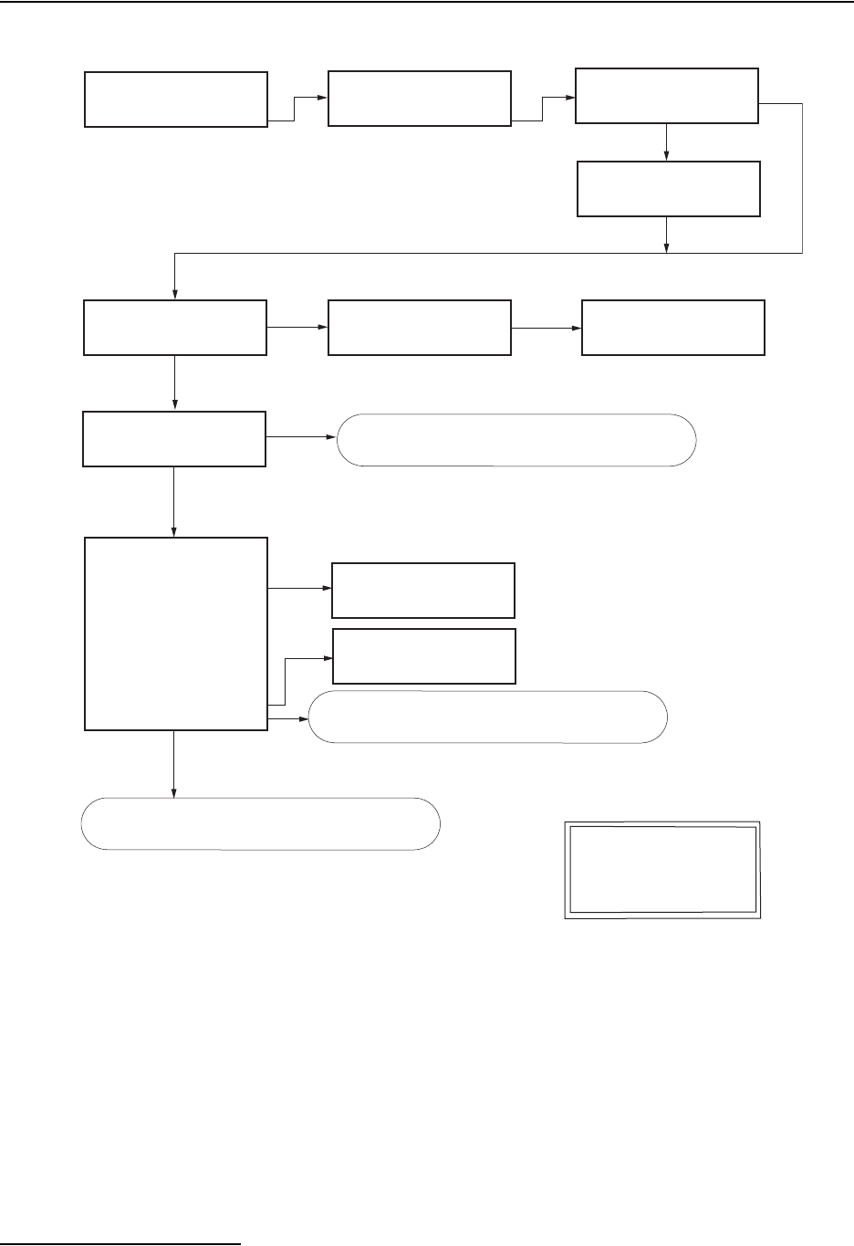
6712FR Refrigerated Sampler
Appendix A Menu Flowcharts
A-20
Figure A-20 Extended Programming: Normal View; Hardware
RUN "EXTENDED 1"
PROGRAM
VIEW REPORT
OTHER FUNCTIONS
MAINTENANCE
MANUAL FUNCTIONS
SOFTWARE OPTIONS
HARDWARE
RUN FLOW THRU PUMP
___SECONDS BEFORE
TAKING READINGS
(0-120)
SET I/Ox:
NONE
<- I/O ENABLE
<- FR-TEMP
-> PGM RUNNING
-> PGM ENABLED
-> 'A' ENABLED
-> 'B' ENABLED
-> PROGRAM DONE
-> 'A' DONE
-> 'B' DONE
-> RUN ERROR
-> FLOW THRU
-> CONDITIONS
See Note A.
RAIN GAUGE
0.01 inch TIP
0.1mm TIP
YES NO
SCAN SDI-12 SONDES
AT TURN-ON TIME?
DO YOU HAVE A
RAIN GAUGE ATTACHED?
YES NO
YES
NO
NEW HARDWARE SETUP--
If applicable
PARTITION MEMORY
WILL LAST __ DAYS
PLEASE WAIT!
Notes
A. <- denotes input signal.
-> denotes output signal.
NEW HARDWARE SETUP--
YES
DOWNLOAD DATA NOW
OR LOSE ALL DATA!
DONE
DOWNLOAD DATA NOW
OR LOSE ALL DATA!
DONE DONE
See Figure A-13.
If scan finds sonde, see Figure A-24.
See Figure A-22.
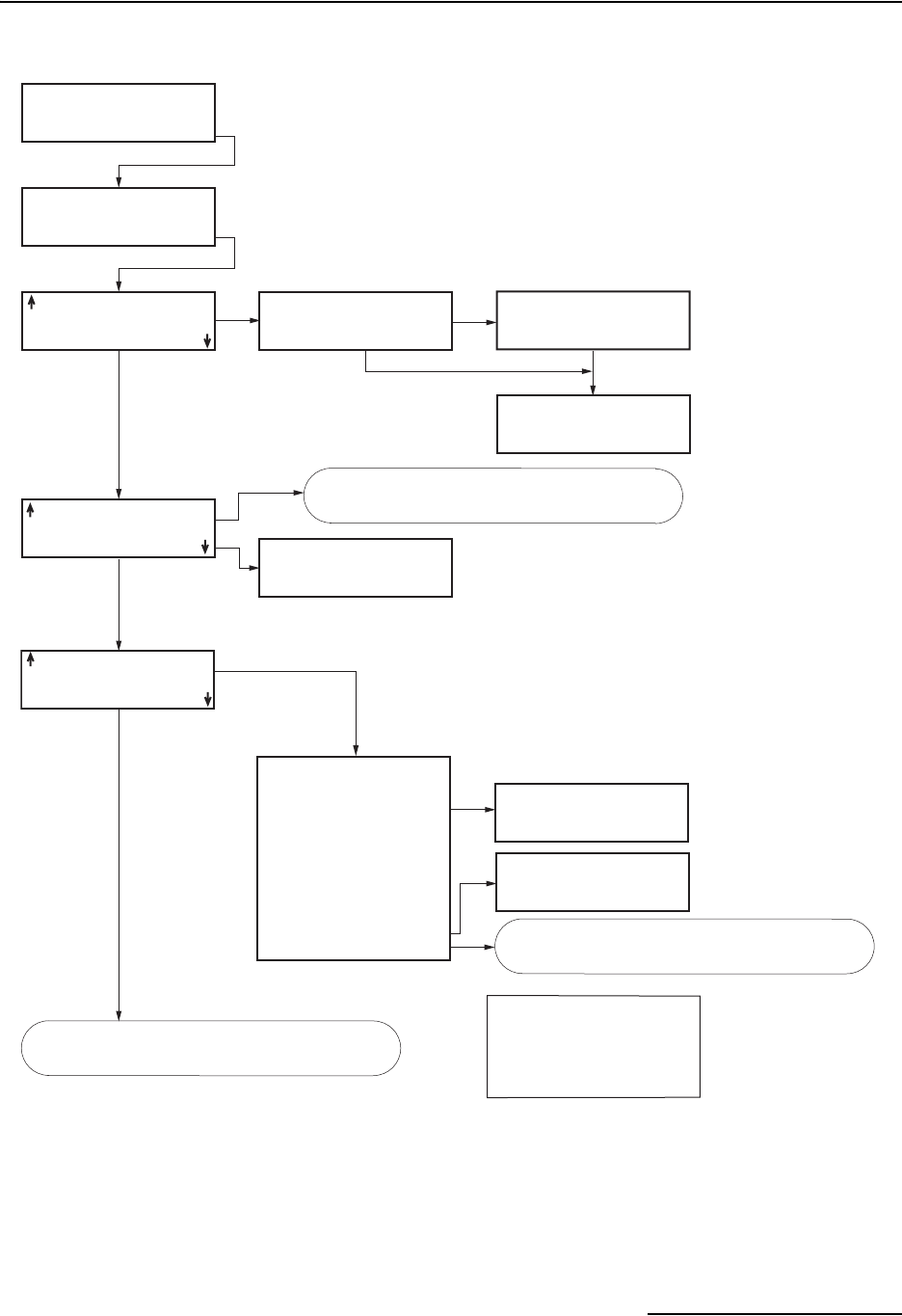
6712FR Refrigerated Sampler
Appendix A Menu Flowcharts
A-21
Figure A-21 Extended Programming: Quick View; Hardware
RUN "ISCO 6712 "
PROGRAM
VIEW REPORT
OTHER FUNCTIONS
MAINTENANCE
MANUAL FUNCTIONS
SOFTWARE OPTIONS
HARDWARE
I/O1=I/O ENABLE
I/O2=PGM RUNNING
I/O3=PROGRAM DONE
See Note A.
0.01 inch TIP
RAIN GAUGE
DO YOU HAVE A
RAIN GAUGE ATTACHED?
YES NO
RAIN GAUGE
0.01 inch TIP
0.1mm TIP
NEW HARDWARE SETUP--
DOWNLOAD DATA NOW
OR LOSE ALL DATA!
DONE
YES
NO
NO SDI-12 SONDE
AUTO SDI-12 SCAN ON
If applicable
Notes A. <- denotes input signal.
-> denotes output signal.
RUN FLOW THRU PUMP
___SECONDS BEFORE
TAKING READINGS
(0-120)
SET I/Ox:
NONE
<- I/O ENABLE
<- FR-TEMP
-> PGM RUNNING
-> PGM ENABLED
-> 'A' ENABLED
-> 'B' ENABLED
-> PROGRAM DONE
-> 'A' DONE
-> 'B' DONE
-> RUN ERROR
-> FLOW THRU
-> CONDITIONS
NEW HARDWARE SETUP--
SCAN SDI-12 SONDES
AT TURN-ON TIME?
YES NO
DOWNLOAD DATA NOW
OR LOSE ALL DATA!
DONE
See Figure A-23.
See Figure A-17.
See Figure A-24.
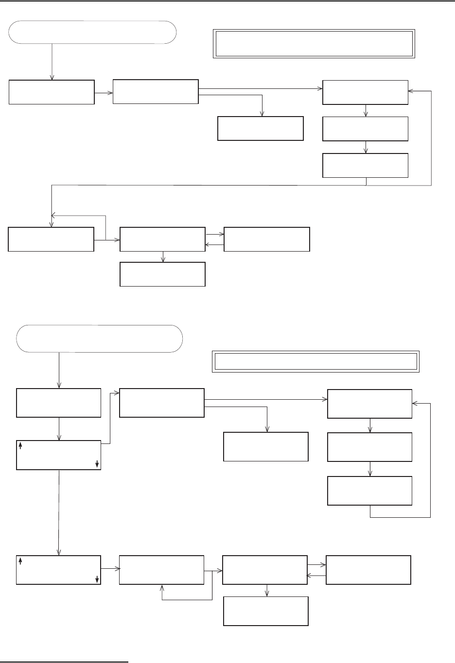
6712FR Refrigerated Sampler
Appendix A Menu Flowcharts
A-22
Figure A-22 Analog and Dialout Screens
Figure A-23 Analog Output and Dialout Quick View Screens
A. Factory installed option. Requires B1 hardware or newer.
B. Requires factory-installed Dialout Modem and B2 hardware or newer.
Notes
ANALOG OUTPUT
HARDWARE HAS NOT
BEEN INSTALLED!
If applicable
See Note A
If applicable
When DECIMAL POINT key is pressed
I/Ox=1,2
I/Ox=3
See Note B
SETUP
MANUAL CONTROL
ANALOG OUTPUT _:
LEVEL VELOCITY
FLOW NONE
SET ANALOG OUTPUT _
TO __.__ mA
DONE
ANALOG OUTPUT _:
0-TO-20 mA
4-TO-20 mA
ANALOG OUTPUT _:
0 mA AT _.__ fps
20 mA AT _.__ fps
(-99999 - 99999)
DIALOUT WHEN I/Ox
BECOMES TRUE?
YES NO
DIALOUT NUMBERS:
SELECT CODE:
, #
*
PAGER
__ MINUTE
DELAY BETWEEN CALLS
(0-99)
Repeat for each channe
l
1.
2.
3.
See Figure A-20.
ANALOG OUTPUT
HARDWARE HAS NOT
BEEN INSTALLED!
If applicable
See Note
SETUP
MANUAL CONTROL
ANALOG OUTPUT _:
LEVEL VELOCITY
FLOW NONE
SET ANALOG OUTPUT _
TO __.__ mA
DONE
ANALOG OUTPUT _:
0-TO-20 mA
4-TO-20 mA
ANALOG OUTPUT _:
0 mA AT _.__ fps
20 mA AT _.__ fps
(-99999 - 99999)
_ ANALOG OUTPUTS
Repeat for each channel
A. Factory installed option. Requires B1 hardware or newer.
Note
I/Ox=1,2
I/Ox
=3
DIALOUT WHEN I/Ox
BECOMES TRUE?
YES NO
DIALOUT NUMBERS:
__ MINUTE
DELAY BETWEEN CALLS
(0-99)
DIALOUT EACH TIME
I/Ox
BECOMES TRUE
1.
2.
3.
When DECIMAL POINT key is pressed
SELECT CODE:
, # * PAGER
See Figure A-21.
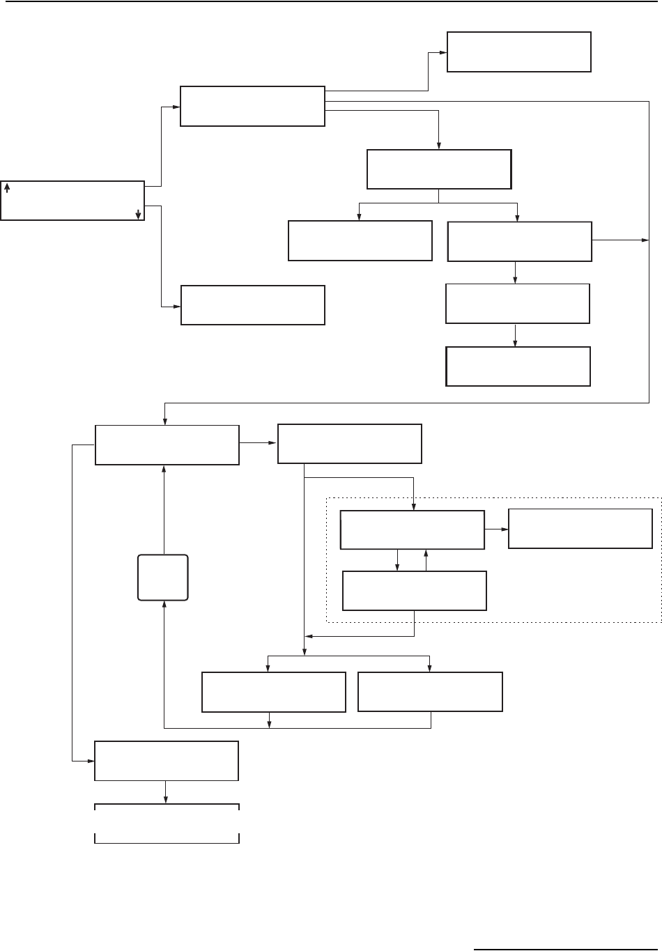
6712FR Refrigerated Sampler
Appendix A Menu Flowcharts
A-23
Figure A-24 SDI-12 Sonde Screens
NO SDI-12 SONDE
SETUP KNOWN SONDES
SCAN SDI-12 SONDES
SCAN SDI-12 SONDES
AT TURN ON TIME?
YES NO
NO SDI-12 SONDE
AUTO SDI-12 SCAN ON
__ SONDE(S) FOUND
PLEASE WAIT!
LOOKING FOR
SDI-12 SONDES
__ PREVIOUSLY
CONFIGURED
SONDES FOUND
DATA FROM SONDE _
1 = OTHER
2 = OTHER
3 = OTHER
DATA FROM SONDE _
4 = OTHER
5 = OTHER
DONE
NEW HARDWARE SETUP
DOWNLOAD DATA NOW
OR LOSE ALL DATA!
DONE
NEW HARDWARE SETUP
DOWNLOAD DATA NOW
OR LOSE ALL DATA!
DONE
SELECT ADDRESS OF
SONDE TO SETUP:
__ __ DONE
Company Model
Optional Information
SONDE AT ADDRESS _
HAS _ DATA VALUES
If No Sondes Found
If Sondes Found
Non-Isco Ready Sondes
Done
Not enough partitions to store
this sonde's data.
Repeat for all data types.
Enough partitions to
store this sonde's data.
PARTITION MEMORY
WILL LAST __ DAYS
NEW HARDWARE SETUP
DOWNLOAD DATA NOW
OR LOSE ALL DATA!
DONE
PARTITION MEMORY
WILL LAST __ DAYS
SONDE _, STORE
TEMPERATURE DATA?
YES NO
LABEL IS: TEMP_
SONDE _, STORE
ALL PARAMETER DATA?
YES NO
Repeat
Until
Done
SONDE _, DATA xx
pH
DO
LEVEL
Proceed to calibration/validation
screens and rest of Hardware screens.

6712FR Refrigerated Sampler
Appendix A Menu Flowcharts
A-24

B-1
6712FR Refrigerated Sampler
Appendix B Material Safety Data Sheets
This appendix provides Material Safety Data sheets for the
internal desiccant used in the 6712 sampler.
Specific questions regarding the use and handling of these
products should be directed to the manufacturer listed in the
MSDS.

6712FR Refrigerated Sampler
Appendix B Material Safety Data Sheets
B-2
101 Christine Drive
Belen, New Mexico 87002
Phone: (505) 864-6691
Fax: (505) 861-2355
MATERIAL SAFETY DATA SHEET -- September 28, 1998
SORB-IT
®
Packaged Desiccant
ISO 9002
SECTION I -- PRODUCT IDENTIFICATION
Trade Name and Synonyms:Silica Gel, Synthetic Amorphous Silica,
Silicon, Dioxide
Chemical Family:Synthetic Amorphous Silica
Formula:SiO
2
.x H
2
O
SECTION II -- HAZARDOUS INGREDIENTS
Components in the Solid Mixture
COMPONENT CAS No % ACGIH/TLV (PPM) OSHA-(PEL)
Amorphous
Silica
63231-67-4 >99 PEL - 20 (RESPIRABLE),
TLV – 5
LIMIT – NONE,
HAZARD -
IRRITANT
˝
Synthetic amorphous silica is not to be confused with crystalline silica such as quartz,
cristobalite or tridymite or with diatomaceous earth or other naturally occurring forms of
amorphous silica that frequently contain crystalline forms.
This product is in granular form and packed in bags for use as a desiccant. Therefore, no
exposure to the product is anticipated under normal use of this product. Avoid inhaling
desiccant dust.
SECTION III -- PHYSICAL DATA
Appearance and Odor: White granules; odorless.
Melting Point: >1600 Deg C; >2900 Deg F
Solubility in Water:Insoluble.
Bulk Density: >40 lbs./cu. ft.
Percent Volatile by Weight @ 1750 Deg F: <10%.

6712FR Refrigerated Sampler
Appendix B Material Safety Data Sheets
B-3
101 Christine Drive
Belen, New Mexico 87002
Phone: (505) 864-6691
Fax: (505) 861-2355
MATERIAL SAFETY DATA SHEET -- September 28, 1998
SORB-IT
®
Packaged Desiccant
ISO 9002
SECTION IV -- FIRE EXPLOSION DATA
Fire and Explosion Hazard - Negligible fire and explosion hazard when exposed to heat
or flame by reaction with incompatible substances.
Flash Point - Nonflammable.
Firefighting Media - Dry chemical, water spray, or foam. For larger fires, use water spray
fog or foam.
Firefighting- Nonflammable solids, liquids, or gases: Cool containers that are exposed
to flames with water from the side until well after fire is out. For massive fire in enclosed
area, use unmanned hose holder or monitor nozzles; if this is impossible, withdraw from
area and let fire burn. Withdraw immediately in case of rising sound from venting safety
device or any discoloration of the tank due to fire.
SECTION V -- HEALTH HAZARD DATA
Health hazards may arise from inhalation, ingestion, and/or contact with the skin and/or
eyes. Ingestion may result in damage to throat and esophagus and/or gastrointestinal
disorders. Inhalation may cause burning to the upper respiratory tract and/or temporary or
permanent lung damage. Prolonged or repeated contact with the skin, in absence of
proper hygiene, may cause dryness, irritation, and/or dermatitis. Contact with eye tissue
may result in irritation, burns, or conjunctivitis.
First Aid (Inhalation) - Remove to fresh air immediately. If breathing has stopped, give
artificial respiration. Keep affected person warm and at rest. Get medical attention
immediately.
First Aid (Ingestion) - If large amounts have been ingested, give emetics to cause
vomiting. Stomach siphon may be applied as well. Milk and fatty acids should be
avoided. Get medical attention immediately.
FirstAid(Eyes)-Washeyesimmediately and carefully for 30minutes with running water.

6712FR Refrigerated Sampler
Appendix B Material Safety Data Sheets
B-4
101 Christine Drive
Belen, New Mexico 87002
Phone: (505) 864-6691
Fax: (505) 861-2355
MATERIAL SAFETY DATA SHEET -- September 28, 1998
SORB-IT
®
Packaged Desiccant
ISO 9002
NOTE TO PHYSICIAN: This product is a desiccant and generates heat as it adsorbs
water. The used product can contain material of hazardous nature. Identify that material
and treat accordingly.
SECTION VI -- REACTIVITY DATA
Reactivity - Silica gel is stable under normal temperatures and pressures in sealed
containers. Moisture can cause a rise in temperature which may result in a burn.
SECTION VII --SPILL OR LEAK PROCEDURES
Notify safety personnel of spills or leaks. Clean-up personnel need protection against
inhalation of dusts or fumes. Eye protection is required. Vacuuming and/or wet methods
of cleanup are preferred. Place in appropriate containers for disposal, keeping airborne
particulates at a minimum.
SECTION VIII -- SPECIAL PROTECTION INFORMATION
Respiratory Protection - Provide a NIOSH/MSHA jointly approved respirator in the
absence of proper environmental control. Contact your safety equipment supplier for
proper mask type.
Ventilation - Provide general and/or local exhaust ventilation to keep exposures below
the TLV. Ventilation used must be designed to prevent spots of dust accumulation or
recycling of dusts.
Protective Clothing - Wear protective clothing, including long sleeves and gloves, to
prevent repeated or prolonged skin contact.
Eye Protection - Chemical splash goggles designed in compliance with OSHA
regulations are recommended. Consult your safety equipment supplier.
6712FR Refrigerated Sampler
Appendix B Material Safety Data Sheets
B-5
101 Christine Drive
Belen, New Mexico 87002
Phone: (505) 864-6691
Fax: (505) 861-2355
MATERIAL SAFETY DATA SHEET -- September 28, 1998
SORB-IT
®
Packaged Desiccant
ISO 9002
SECTION IX -- SPECIAL PRECAUTIONS
Avoid breathing dust and prolonged contact with skin. Silica gel dust causes eye irritation
and breathing dust may be harmful.
* No Information Available
HMIS (Hazardous Materials Identification System) for this product is as
follows:
Health Hazard 0
Flammability 0
Reactivity 0
Personal Protection HMIS assigns choice of personal protective equipment to the
customer, as the raw material supplier is unfamiliar with the
condition of use.
The information contained herein is based upon data considered true and accurate. However, United Desiccants makes no warranties
expressed or implied, as to the accuracy or adequacy of the information contained herein or the results to be obtained from the use
thereof. This information is offered solely for the user's consideration, investigation and verification. Since the use and conditions of
use of this information and the material described herein are not within the control of United Desiccants, United Desiccants assumes no
responsibility for injury to the user or third persons. The material described herein is sold only pursuant to United Desiccants' Terms
and Conditions of Sale, including those limiting warranties and remedies contained therein. It is the responsibility of the user to
determine whether any use of the data and information is in accordance with applicable federal, state or local laws and regulations.
6712FR Refrigerated Sampler
Appendix B Material Safety Data Sheets
B-6
*Optional Indicating Silica Gel
Material Safety Data Sheet
Indicating Silica Gel
Identity (Trade Name as Used on Label)
Manufacturer
:MULTISORB TECHNOLOGIES, INC.
(formerly Multiform Desiccants, Inc.)
MSDS Number* : M75
Address: 325 Harlem Road
Buffalo, NY 14224
CAS Number* :
Phone Number (For Information): 716/824-8900 Date Prepared: July 6, 2000
Emergency Phone
Number: 716/824-8900 Prepared By* : G.E. McKedy
Section 1 - Material Identification and Information
Components - Chemical Name & Common Names
(Hazardous Components 1% or greater; Carcinogens 0.1% or
greater)
%* OSHA
PEL ACGIH
TLV OTHER LIMITS
RECOMMENDE
D
Silica Gel SiO298.0 6mg/m3
(total dust) 10mg/m3
(total dust)
Cobalt Chloride >2.0 0.05mg/m3
(TWA cobalt
metal dust &
fume)
.05mg/m3
(Cobalt, TWA)
Non-Hazardous Ingredients
TOTAL 100
Section 2 - Physical/Chemical Characteristics
Boiling
Point N/A Specific Gravity
(H20 = 1) 2.1
Vapor Pressure
(mm Hg and Temperature N/A Melting
Point N/A
Vapor
Density
(Air =1)
N/A Evaporation Rate
(__________=1) N/A
Solubility
in Water Insoluble, but will adsorb moisture. Water
Reactive Not reactive, but will adsorb moisture.
Appearance
and Odor Purple crystals, no odor.
Section 3 - Fire and Explosion Hazard Data
Flash Point and
Methods Used N/A Auto-Ignition
Temperature N/A Flammability Limits in
Air % by Volume N/A LEL UEL
Extinguisher
Media Dry chemical, carbon dioxide and foam can be used.
Special Fire
Fighting Procedures Water will generate heat due to the silica gel which will adsorb water and liberate heat.
Unusual Fire and
Explosion Hazards When exposed to water, the silica gel can get hot enough to reach the boiling point of water. Flooding with
water will reduce the temperature to safe limits.
Section 4 - Reactivity Hazard Data
STABILITY
Stable
Unstable
Conditions
To Avoid Moisture and high humidity environments.
Incompatibility
(Materials to Avoid) Water.
Hazardous
Decomposition
Products
Carbon dioxide, carbon monoxide, water
HAZARDOUS POLYMERIZATION
May Occur Conditions
To Avoid None.
6712FR Refrigerated Sampler
Appendix B Material Safety Data Sheets
B-7
*Optional Indicating Silica Gel
Page 2
Section 5 - Health Hazard Data
PRIMARY ROUTES Inhalation Ingestion
OF ENTRY Skin Absorption Not Hazardous CARCINOGEN NTP OSHA
LISTED IN IARC Monograph Not Listed
HEALTH HAZARDS Acute May cause eye, skin and mucous membrane irritation.
Chronic Prolonged inhalation may cause lung damage.
Signs and Symptoms
of Exposure Drying and irritation.
Medical Conditions
Generally Aggravated by Exposure Asthma.
EMERGENCY FIRST AID PROCEDURES - Seek medical assistance for further treatment, observation and support if necessary.
Eye Contact Flush with water for at least 15 minutes.
Skin
Contact Wash affected area with soap and water.
Inhalation Remove affected person to fresh air.
Ingestion Drink at least 2 glasses of water.
Section 6 - Control and Protective Measures
Respiratory Protection
(Specify Type) Use NIOSH approved dust mask or respirator.
Protective
Gloves Light cotton gloves. Eye Protection Safety glasses.
VENTILATION Local Exhaust Mechanical (General) Special
TO BE USED
Other (Specify)
Other Protective
Clothing and Equipment None.
Hygienic Work
Practices Avoid raising dust. Avoid contact with skin, eyes and clothing.
Section 7 - Precautions for Safe Handling and Use/Leak Procedures
Steps to be Taken if Material
Is
Spilled Or Released
Sweep or vacuum up and place the spilled material in a waste disposal container. Avoid raising dust.
Waste Disposal
Methods Dispose in an approved landfill according to federal, state and local regulations.
Precautions to be
Taken
In Handling and
Storage
Cover promptly to avoid blowing dust. Wash after handling.
Other Precautions and/or Special
Hazards Keep in sealed containers away from moisture. The silica gel will readily adsorb moisture.

6712FR Refrigerated Sampler
Appendix B Material Safety Data Sheets
B-8
C-1
6712FR Refrigerated Sampler
Appendix C General Safety Procedures
In field installations of Isco wastewater samplers and associated
equipment, the safety of the personnel involved should be the
foremost consideration. The following sections provide safety pro-
cedures for working in and around manholes and sewers. the
first section offers general safety advice. The second section deals
with the special problem of hazardous gases found in sewers.
WARNING
The 6712FR has not been approved for use in hazardous
locations as defined by the National Electrical Code.
CAUTION
Before any sampler is installed, the proper safety precautions
must be taken. The following discussions of safety procedures
are only general guidelines. Each situation in which you install
a flow meter varies. You must take into account the individual
circumstances you are in. Additional safety considerations,
other than those discussed here, may be required.
C.1 Practical Safety
Precautions
The following procedures are those used by Black & Veatch, a
respected consulting firm, and are published here by permission.
Field personnel must keep safety uppermost in their minds at all
times. When working above ground, rules of common sense and
safety prevail. However, when entering manholes, strict safety
procedures must be observed. Failure to do so could jeopardize
not only your own life, but also the lives of other crew members.
C.1.1 Hazards There are many hazards connected with entering manholes.
Some of the most common hazards are:
Adverse Atmosphere – The manhole may contain flammable
or poisonous gases or the atmosphere may be deficient in oxygen.
orced ventilation may be necessary.
Deteriorated Rungs – Manhole steps may be corroded and not
strong enough to support a man. It may be difficult to inspect the
rungs because of poor lighting.
Traffic – Whenever manholes are located in the traveled way,
barricades and warning devices are essential to direct traffic
away from an open manhole.
Falling Objects – Items placed near the manhole opening may
fall and injure a worker in the manhole.

6712FR Refrigerated Sampler
Appendix C General Safety Procedures
C-2
Sharp Edges – Sharp edges of items in or near a manhole may
cause cuts or bruises.
Lifting Injuries – Unless proper tools are used to remove
manhole covers, back injuries or injuries to hands or feet may
result.
C.1.2 Planning Advance planning should include arrangements for test
equipment, tools, ventilating equipment, protective clothing,
traffic warning devices, ladders, safety harness, and adequate
number of personnel. Hasty actions may result in serious
injuries. Time spent in the manhole should be kept to a
minimum.
C.1.3 Adverse Atmospheres [Refer to Table C-1, Hazardous Gases, at the end of this
appendix.] Before workers enter a manhole, tests should be made
for explosive atmosphere, presence of hydrogen sulfide, and
oxygen deficiency. Combustible or toxic vapors may be heavier
than air, so the tests on the atmosphere must be run at least 3/4 of
the way down the manhole.
Whenever adverse atmosphere is encountered, forced ventilation
must be used to create safe conditions. After the ventilating
equipment has been operated for a few minutes, the atmosphere
in the manhole should be retested before anyone enters the
manhole.
When explosive conditions are encountered, the ventilating
blower should be placed upwind to prevent igniting any gas that
is emerging from the opening. When a gasoline engine blower is
used, it must be located so that exhaust fumes cannot enter the
manhole.
If testing equipment is not available, the manhole should be
assumed to contain an unsafe atmosphere and forced ventilation
must be provided. It should never be assumed that a manhole is
safe just because there is no odor or the manhole has been
entered previously.
C.1.4 Entering Manholes Since the top of the manhole is usually flush with the sur-
rounding surface, there may not be anything for the person who
is entering the manhole to grab on to steady himself. Persons
who are entering manholes should not be permitted to carry any-
thing in their hands as they enter the manhole, to ensure that
their hands will be free to hold on or grab if they slip. A good
method for entering a manhole is to sit on the surface facing the
manhole steps or ladder, with the feet in the hole and the arms
straddling the opening for support. As the body slides forward
and downward, the feet can engage a rung, and the back can rest
against the opposite side of the opening. If there is any doubt
about the soundness of the manhole steps, a portable ladder
should be used.
A person should never enter a manhole unless he is wearing per-
sonal safety equipment, including a safety harness and a hard
hat. Two persons should be stationed at the surface continuously
while anyone is working inside a manhole, to lift him out if he is

6712FR Refrigerated Sampler
Appendix C General Safety Procedures
C-3
overcome or injured. One man cannot lift an unconscious man
out of a manhole. The persons stationed at the surface should
also function as guards to keep people and vehicles away from
the manhole opening. To avoid a serious injury, a person should
not be lifted out of a manhole by his arm unless it is a dire emer-
gency.
When more than one person must enter a manhole, the first
person should reach the bottom and step off the ladder before the
next one starts down. When two men climb at the same time, the
upper one can cause the lower one to fall by slipping or stepping
on his fingers.
C.1.5 Traffic Protection In addition to traffic cones, markers, warning signs, and barri-
cades, a vehicle or a heavy piece of equipment should be placed
between the working area and oncoming traffic. Flashing
warning signals should be used to alert drivers and pedestrians.
Orange safety vests should be worn by personnel stationed at the
surface when the manhole is located in a vehicular traffic area.
C.1.6 Falling Objects All loose items should be kept away from the manhole opening.
This applies to hand tools as well as stones, gravel and other
objects.
C.1.7 Removing the Covers Manhole covers should be removed with a properly designed
hook. Use of a pick ax, screwdriver, or small pry bar may result
in injury. A suitable tool can be made from 3/4-inch round or hex
stock. Two inches of one end should be bent at a right angle and
the other end should be formed into a D-handle wide enough to
accommodate both hands. Even with this tool, care must be exer-
cised to prevent the cover from being dropped on the toes. The
2-inch projection should be inserted into one of the holes in the
cover, the handle grasped with both hands, and the cover lifted
by straightening the legs which have been slightly bent at the
knees.
C.1.8 Other Precautions Other precautions which should be taken when entering a
manhole are:
• Wear a hard hat.
• Wear coveralls or removable outer garment that can be
readily removed when the work is completed.
• Wear boots or nonsparking safety shoes.
• Wear rubberized or waterproof gloves.
• Wear a safety harness with a stout rope attached.
• Do not smoke.
• Avoid touching yourself above the collar until you have
cleaned your hands.

6712FR Refrigerated Sampler
Appendix C General Safety Procedures
C-4
C.1.9 Emergencies Every member of the crew should be instructed on procedures to
be followed in cases of an emergency. It is the duty of each crew
chief to have a list of emergency phone numbers, including the
nearest hospital and ambulance service, police precinct, fire
station, and rescue or general emergency number.
C.1.10 Field Equipment The following equipment will be available for use:
C.2 Lethal Atmospheres in
Sewers
The following is an article written by Dr. Richard D. Pomeroy,
and published in the October 1980 issue of Deeds & Data of the
WPCF. Dr. Pomeroy is particularly well known for his studies,
over a period of nearly 50 years, in the field of the control of
hydrogen sulfide and other odors in sewers and treatment plants.
He has personally worked in a great many functioning sewers. In
the earlier years he did so, he admits, with little knowledge of
the grave hazards to which he exposed himself.
It is gratifying that the subject of hazards to people working in
sewers is receiving much more attention than in past years, and
good safety procedures are prescribed in various publications on
this subject. It is essential that people know and use correct pro-
cedures.
It is less important to know just what the hazardous components
of sewer atmospheres are, as safety precautions should in
general be broadly applicable, but there should be a reasonable
understanding of this subject. It is disturbing to see statements
in print that do not reflect true conditions.
One of the most common errors is the assumption that people
have died from a lack of oxygen. The human body is able to
function very well with substantially reduced oxygen concentra-
tions. No one worries about going to Santa Fe, New Mexico, (elev.
2,100 meters), where the partial pressure of oxygen is equal to
16.2% (a normal atmosphere is about 21%) oxygen. When first
going there, a person may experience a little ‘shortness of breath’
following exercise. People in good health are not afraid to drive
over the high passes in the Rocky Mountains. At Loveland Pass,
oxygen pressure is 13.2% of a normal atmosphere. At the top of
Mt. Whitney, oxygen is equal to 12.2%t. Many hikers go there,
and to higher peaks as well. After adequate acclimation, they
may climb to the top of Mt. Everest, where oxygen is equal to
only 6.7%.
Blowers Gloves Traffic cones
Breathing apparatus Hard Hats Coveralls
Harnesses First aid kits Manhole irons
Emergency flashers Pick axes Flashlights
Rain slickers Mirrors Ropes
Gas detectors Safety vests Gas masks
Waders”

6712FR Refrigerated Sampler
Appendix C General Safety Procedures
C-5
The lowest oxygen concentrations that I have observed in a
sewer atmosphere was 13 percent. It was in a sealed chamber,
near sea level, upstream from an inverted siphon on a metro-
politan trunk. A man would be foolish to enter the chamber.
Without ventilation, he might die, but not from lack of oxygen.
It seems unlikely that anyone has ever died in a sewer from suf-
focation, that is, a lack of oxygen. Deaths have often been
attributed to ‘asphyxiation.’ This is a word which, according to
the dictionary, is used to mean death from an atmosphere that
does not support life. The word has sometimes been misinter-
preted as meaning suffocation, which is only one kind of asphyxi-
ation.
In nearly all cases of death in sewers, the real killer is hydrogen
sulfide. It is important that this fact be recognized. Many cities
diligently test for explosive gases, which is very important, and
they may measure the oxygen concentration which usually is
unimportant, but they rarely measure H2S. Death has occurred
where it is unlikely that there was any measurable reduction in
the oxygen concentration. Waste water containing 2 mg per liter
of dissolved sulfide, and at a pH of 7.0, can produce, in a chamber
with high turbulence, a concentration of 300 PPM H2S, in the air.
This is considered to be a lethal concentration. Many people have
died from H2S, not only in sewers and industries, but also from
swamps and from hot springs. In one resort area, at least five
persons died from H2S poisoning before the people were ready to
admit that H2S is not a therapeutic agent. Hardly a year passes
in the U.S. without a sewer fatality from H2S as well as deaths
elsewhere in the world.
The presence of H2S in a sewer atmosphere is easily determined.
A bellows-and-ampoule type of tester is very satisfactory for the
purpose, even though it is only crudely quantitative. When using
a tester of this type, do not bring the air to the ampoule by way of
a tube, as this may change the H2S concentration. Hang the
ampoule in the air to be tested, with a suction tube to the bulb or
bellows.
Lead acetate paper is very useful as a qualitative indicator. It
cannot be used to estimate the amount of sulfide, but it will
quickly turn black in an atmosphere containing only a tenth of a
lethal concentration.
Electrodes or other similar electrical indicating devices for H2S
in air have been marketed. Some of them are known to be unre-
liable, and we know of none that have proved dependable. Do not
use one unless you check it at frequent intervals against air con-
taining known H2S concentrations. A supposed safety device that
is unreliable is worse than none at all.
Remember that the nose fails, too, when it comes to sensing dan-
gerous concentrations of H2S.
Various other toxic gases have been mentioned in some publica-
tions. It is unlikely that any person has been asphyxiated in a
sewer by any of those other gases, except possibly chlorine. The
vapor of gasoline and other hydrocarbons is sometimes present in

6712FR Refrigerated Sampler
Appendix C General Safety Procedures
C-6
amounts that could cause discomfort and illness, but under that
condition, the explosion hazard would be far more serious. The
explosimeter tests, as well as the sense of smell, would warn of
the danger. Pipelines in chemical plants might contain any
number of harmful vapors. They, too, are sensed by smell and
explosimeter tests if they get into the public sewer. Such occur-
rences are rare.
The attempt to instill a sense of urgency about real hazards is
diluted if a man is told to give attention to a long list of things
that in fact are irrelevant.
Be very careful to avoid high H2S concentrations, flammable
atmospheres, and hazards of physical injuries. Remember that
much H2S may be released by the stirring up of sludge in the
bottom of a structure. Obey your senses in respect to irritating
gases, such as chlorine (unconsciousness comes suddenly from
breathing too much). Be cautious about strange odors. Do not
determine percent oxygen in the air. There is a danger that the
result will influence a man's thinking about the seriousness of
the real hazards. Most important, use ample ventilation, and do
not enter a potentially hazardous structure except in a good
safety harness with two men at the top who can lift you out.”
C.3 Hazardous Gases The following table contains information on the properties of
hazardous gases.
Table C-1 Hazardous Gases
Gas Chemical
Formula
Common
Properties
Specific
Gravity
or Vapor
Density
Air =1
Physiological
Effect
Max
Safe 60
Min.
Exposure
ppm
Max. Safe
8 Hour
Exposure
ppm
Explosive
Range (% by
vol. in air)
Limits
lower/upper
Likely
Location
of
Highest
Concentration
Most
Common
Sources
Simplest and
Cheapest
Safe Method
of Testing
Ammonia NH3Irritant and
poisonous. Col-
orless
with characteris-
tic
odor.
0.60 Causes throat
and
eye irritation at
0.05%, cough-
ing
at 0.17%. Short
exposure at
0.5%
to 1% fatal.
300
to
500
85 16 25 Near top.
Concentrates
in closed up-
per spaces
Sewers,
chemical
feed
rooms.
Detectable
odor at low
concentrations
Benzene C6H6Irritant, colorless
anesthetic
2.77 Slight symp-
toms
after several
hours
exposure at
0.16% to 0.32%.
2% rapidly
fatal.
3,000
to
5,000
25 1.3 7.1 At bottom. Industrial
wastes,
varnish,
solvents.
Combustible
gas indicator
Carbon
Bisulfide
CS2Nearly odorless
when pure, color-
less, anesthetic.
Poisonous.
2.64 Very poison-
ous,
irritating, vom-
iting,
convulsions,
psychic distur-
bance.
— 15 1.3 44.0 At bottom An insecti-
cide
Combustible
gas indicator

6712FR Refrigerated Sampler
Appendix C General Safety Procedures
C-7
Carbon
Dioxide
CO2Asphyxiant, Col-
orless, odorless.
When breathed
in large quanti-
ties, may cause
acid taste.
Non-flammable.
Not generally
present in dan-
gerous amounts
unless an oxygen
deficiency exists.
1.53 Cannot be
endured at 10%
more than a
few minutes,
even if subject
is at rest and
oxygen content
is normal. Acts
on respiratory
nerves.
40,000
to
60,000
5,000 — — At bottom;
when heated
may stratify
at points
above bottom.
Products
of com-
bustion,
sewer gas,
sludge.
Also issues
from car-
bonaceous
strata.
Oxygen
deficiency
indicator
Carbon
Monox-
ide
CO Chemical
asphyxiant. Col-
orless, odorless,
tasteless.
Flammable.
Poisonous.
0.97 Combines with
hemoglobin of
blood. Uncon-
sciousness in
30 min. at 0.2%
to 0.25%. Fatal
in 4 hours at
0.1%. Head-
ache in few
hours at 0.02%.
400 50 12.5 74.0 Near top, espe-
cially if present
with illuminat-
ing gas.
Manufac-
tured gas,
flue gas,
products
of com-
bustion,
motor
exhausts.
Fires of
almost any
kind.
CO ampoules.
Carbon
Tetra - Chl
oride
CCl4Heavy, ethereal
odor.
5.3 Intestinal
upset, loss of
consciousness,
possible renal
damage, respi-
ratory failure.
1,000
to
1,500
100 — — At bottom. Industrial
wastes,
solvent,
cleaning
Detectable
odor
at low concen-
trations.
Chlorine Cl2Irritant. Yel-
low-green color.
Choking odor
detectable in very
low concentra-
tions. Non-flam-
mable.
2.49 Irritates respi-
ratory tract.
Kills most ani-
mals in a very
short time at
0.1%.
4 1 — — At bottom. Chlorine
cylinder
and feed
line leaks.
Detectable
odor at low
concentra-
tions.
Formal-
dehyde
CH2O Colorless, pun-
gent suffocating
odor.
1.07 Irritating to the
nose.
— 10 7.0 73.0 Near bottom. Incom-
plete com-
bustion of
organics.
Common
air pollut-
ant, fungi-
cide.
Detectable
odor.
Gasoline C5H12
to
C9H20
Volatile solvent.
Colorless. Odor
noticeable at
0.03%. Flamma-
ble.
3.0
to
4.0
Anesthetic
effects when
inhaled. Rap-
idly fatal at
2.4%. Danger-
ous for short
exposure at 1.1
to 2.2%.
4,000
to
7,000
1,000 1.3 6.0 At bottom. Service
stations,
garages,
storage
tanks,
houses.
1. Combusti-
ble gas indi-
cator.
2. Oxygen
deficiency
indicator.**
Hydrogen H2Simple asphyx-
iant. Colorless,
odorless, taste-
less. Flammable
0.07 Acts mechani-
cally to deprive
tissues of oxy-
gen. Does not
support life.
— — 4.0 74.0 At top. Manufac-
tured gas,
sludge
digestion
tank gas,
electroly-
sis of
water.
Rarely
from rock
strata.
Combustible
gas indicator.
Hydrogen
Cyanide
HCN Faint odor of bit-
ter almonds.
Colorless gas
0.93 Slight symp-
toms appear
upon exposure
to 0.002% to
0.004%. 0.3%
rapidly fatal.
— 10 6.0 40.0 Near top. Insecti-
cide and
rodenti-
cide.
Detector tube
Table C-1 Hazardous Gases (Continued)
Gas Chemical
Formula
Common
Properties
Specific
Gravity
or Vapor
Density
Air =1
Physiological
Effect
Max
Safe 60
Min.
Exposure
ppm
Max. Safe
8 Hour
Exposure
ppm
Explosive
Range (% by
vol. in air)
Limits
lower/upper
Likely
Location
of
Highest
Concentration
Most
Common
Sources
Simplest and
Cheapest
Safe Method
of Testing

6712FR Refrigerated Sampler
Appendix C General Safety Procedures
C-8
Gas Chemical
Formula
Common
Properties
Specific
Gravity or
Vapor
Density
Air = 1
Physiological
Effect*
Max
Safe
60 Min.
Exposure
ppm
Max.
Safe
8 Hour
Exposure
ppm
Explosive Range
(% by vol.
in air.)
Limits
lower/upper
Likely
Location
of
Highest
Concentration
Most
Common
Sources
Simplest and
Cheapest
Safe Method
of Testing
Hydro-
gen Sul-
fide
H2S Irritant and poi-
sonous volatile
compound. Rot-
ten egg odor in
small concentra-
tions. Exposure
for 2 to 15 min. at
0.01% impairs
sense of smell.
Odor not evident
at high concen-
trations. Color-
less. Flammable.
1.19 Impairs sense
of smell, rap-
idly as concen-
tration
increases.
Death in few
minutes at
0.2%. Exposure
to 0.07 to 0.1%
rapidly causes
acute poison-
ing. Paralyzes
respiratory
center.
200
to
300
20 4.3
45.0
Near bottom,
but may be
above bottom if
air is heated and
highly humid.
Coal gas,
petro-
leum,
sewer gas.
Fumes
from blast-
ing under
some con-
ditions.
Sludge gas.
1. H2S
Ampoule.
2. 5% by weight
lead acetate
solution.
Methane CH4Simple asphyx-
iant.
Colorless, odor-
less, tasteless,
flammable.
0.55 Acts mechani-
cally to deprive
tissues of oxy-
gen. Does not
support life.
Probably no
limit, pro-
vided oxygen
percent-age
is sufficient
for life.
— 5.0 15.0 At top, increas-
ing to certain
depth.
Natural
gas, sludge
gas, manu-
factured
gas, sewer
gas. Strata
of sedi-
mentary
origin. In
swamps or
marshes.
1. Combustible
gas indicator
2. Oxygen defi-
ciency indica-
tor.
Nitrogen N2Simple asphyx-
iant. Colorless,
tasteless.
Non-flammable.
Principal constit-
uent of air. (about
79%).
0.97 Physiologically
inert.
— — — — Near top, but
may be found
near bottom.
Sewer gas.
sludge gas.
Also issues
from some
rock strata.
Oxygen
deficiency
indicator.
Nitrogen
Oxides
NO
N2O
NO2
Colorless
Colorless,
sweet odor.
Reddish-brown.
Irritating odor.
Deadly poison
1.04
1.53
1.58
60 to 150 ppm
cause irritation
and coughing.
Asphyxiant.
100 ppm dan-
gerous.
200 ppm fatal.
50 10 — — Near bottom. Industrial
wastes.
Common
air pollut-
ant.
NO2 detector
tube.
Oxygen O2Colorless, odor-
less, tasteless.
Supports com-
bustion.
1.11 Normal air con-
tains 20.8% of
O2. Man can tol-
erate down to
12%. Minimum
safe 8 hour
exposure, 14 to
16%. Below 10%,
dangerous to
life. Below 5 to
7% probably
fatal.
— — — — Variable at dif-
ferent levels.
Oxygen
depletion
from poor
ventila-
tion and
absorp-
tion, or
chemical
consump-
tion of
oxygen.
Oxygen defi-
ciency indica-
tor.
Ozone O3Irritant and poi-
sonous. Strong
electrical odor.
Strong oxidizer.
Colorless. At 1
ppm, strong sul-
fur-like odor.
1.66 Max. naturally
occurring level
is 0.04 ppm.
0.05 ppm
causes irrita-
tion of eyes and
nose. 1 to 10
ppm causes
headache, nau-
sea; can cause
coma. Symp-
toms similar to
radiation dam-
age.
0.08 0.04 — — Near bottom. Where
ozone is
used for
disinfec-
tion.
Detectable
odor
at 0.015 ppm.
Table C-1 Hazardous Gases (Continued)
Gas Chemical
Formula
Common
Properties
Specific
Gravity
or Vapor
Density
Air =1
Physiological
Effect
Max
Safe 60
Min.
Exposure
ppm
Max. Safe
8 Hour
Exposure
ppm
Explosive
Range (% by
vol. in air)
Limits
lower/upper
Likely
Location
of
Highest
Concentration
Most
Common
Sources
Simplest and
Cheapest
Safe Method
of Testing
6712FR Refrigerated Sampler
Appendix C General Safety Procedures
C-9
Sludge
Gas
—*** Mostly a simple
asphyxiant. May
be practically
odorless, taste-
less.
Variable Will not support
life.
No data. Would
vary widely with composi-
tion.
5.3 19.3 Near top of
structure.
From
digestion
of sludge.
See compo-
nents.
Sulfur
Dioxide
SO2Colorless, pun-
gent odor. Suffo-
cating, corrosive,
poisonous,
non-flammable.
2.26 Inflammation of
the eyes. 400 to
500 ppm imme-
diately fatal.
50
to
100
10 — — At bottom, can
combine with
water to form
sulfurous acid.
Industrial
waste,
combus-
tion, com-
mon air
pollutant.
Detectable
taste and odor
at low concen-
tration.
Tolu e ne C5H12
to
C9H20
Colorless, ben-
zene-like odor.
3.14 At 200-500 ppm,
headache, nau-
sea, bad taste,
lassitude.
200 100 1.27 7.0 At bottom. Solvent. Combustible
gas indicator.
Turpentine C10H16 Colorless, Char-
acteristic odor.
4.84 Eye irritation.
Headache, diz-
ziness, nausea,
irritation of the
kidneys.
— 100 At bottom. Solvent,
used in
paint.
1. Detectable
odor at low
concentration
s.
2.Combustible
gas indica-
tor.
Xylene C8H10 Colorless, flam-
mable
3.66 Narcotic in high
concentrations.
less toxic than
benzene.
— 100 1.1 7.0 At bottom. Solvent Combustible
gas indicator.
* Percentages shown represent volume of gas in air.
** For concentration over 0.3%.
***Mostly methane and carbon dioxide with small amounts of hydrogen, nitrogen, hydrogen sulfide, and oxygen; occasionally traces of carbon monoxide.
Table C-1 Hazardous Gases (Continued)
Gas Chemical
Formula
Common
Properties
Specific
Gravity
or Vapor
Density
Air =1
Physiological
Effect
Max
Safe 60
Min.
Exposure
ppm
Max. Safe
8 Hour
Exposure
ppm
Explosive
Range (% by
vol. in air)
Limits
lower/upper
Likely
Location
of
Highest
Concentration
Most
Common
Sources
Simplest and
Cheapest
Safe Method
of Testing

6712FR Refrigerated Sampler
Appendix C General Safety Procedures
C-10

D-1
6712FR Refrigerated Sampler
Appendix D Replacement Parts List
D.1 Replacement Parts
Diagrams and Listings
Replacement parts are called out in illustrations in this section.
Reference the call-outs in the accompanying tables to determine
the part number for the item.
Replacement parts can be purchased by contacting Teledyne
Isco’s Customer Service Department.
Teledyne Isco, Inc.
Customer Service Department
P.O. Box 82531
Lincoln, NE 68501 USA
Phone: (800) 228-4373
(402) 464-0231
FAX:(402) 465-3022
E-mail:IscoInfo@teledyne.com
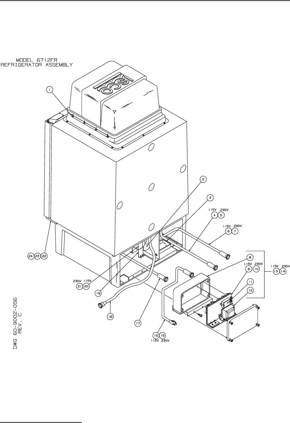
6712FR Refrigerated Sampler
Appendix D Replacement Parts List
D-2
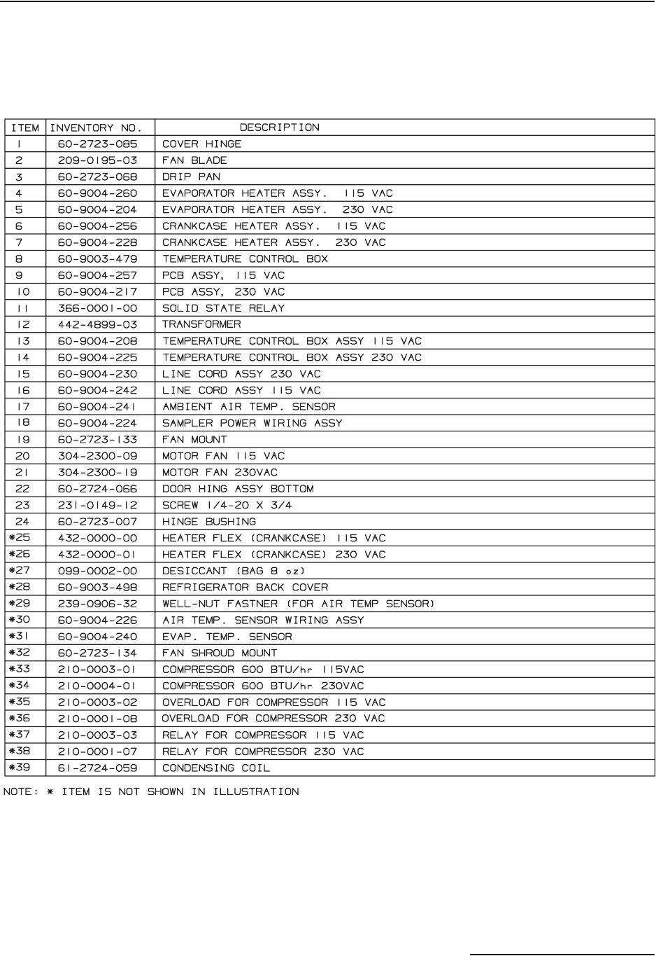
6712FR Refrigerated Sampler
Appendix D Replacement Parts List
D-3
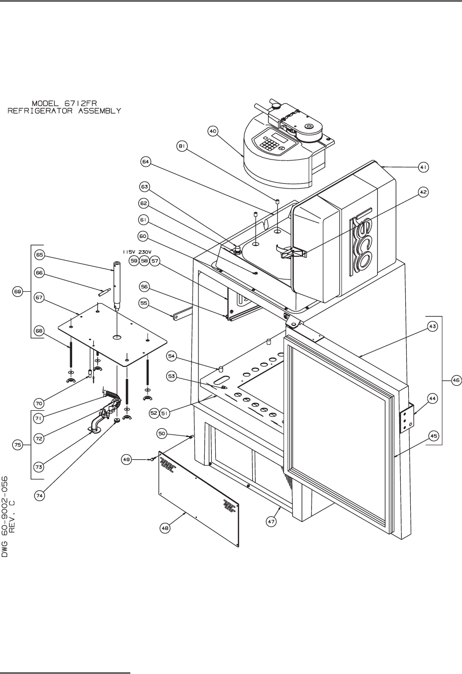
6712FR Refrigerated Sampler
Appendix D Replacement Parts List
D-4
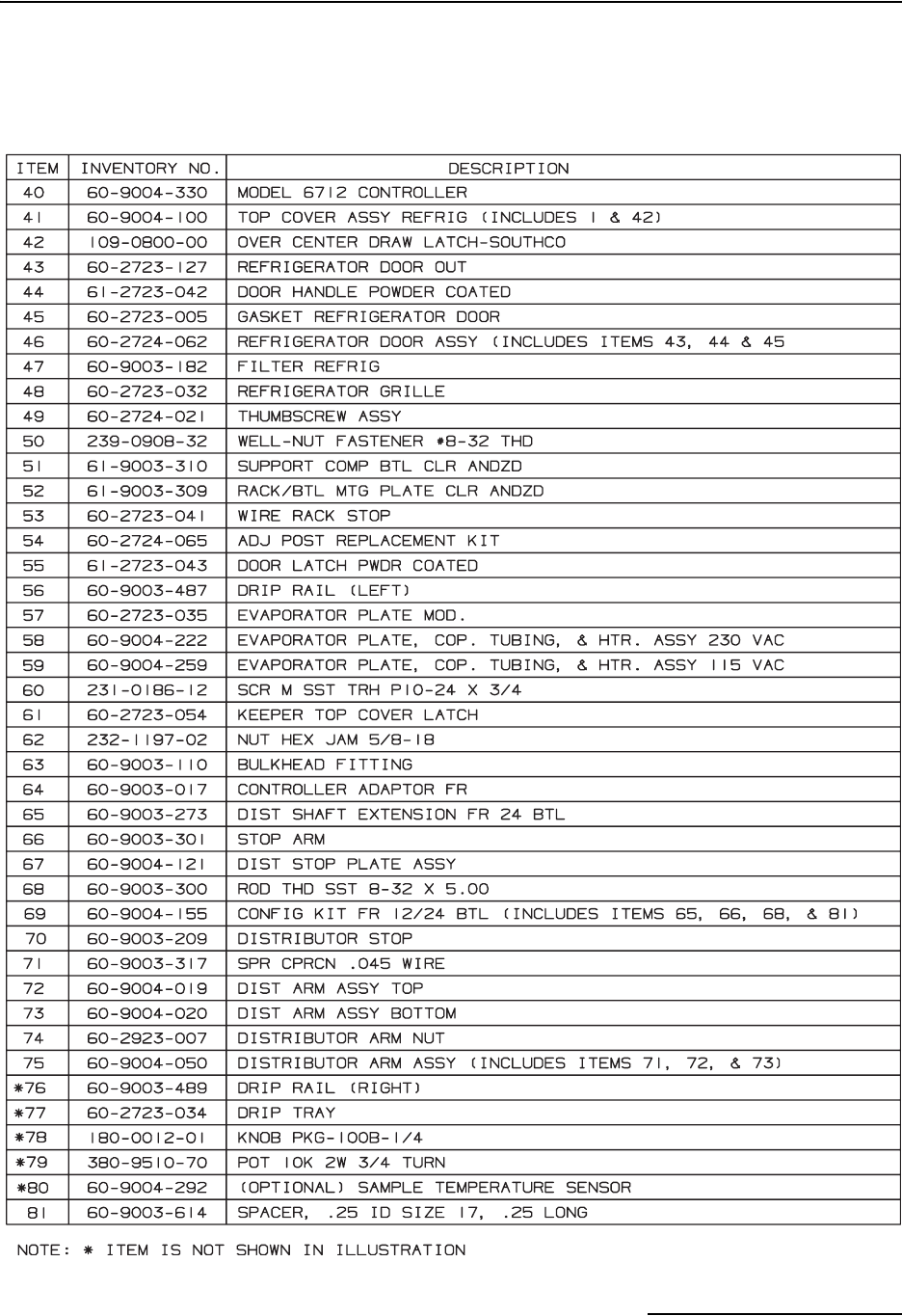
6712FR Refrigerated Sampler
Appendix D Replacement Parts List
D-5
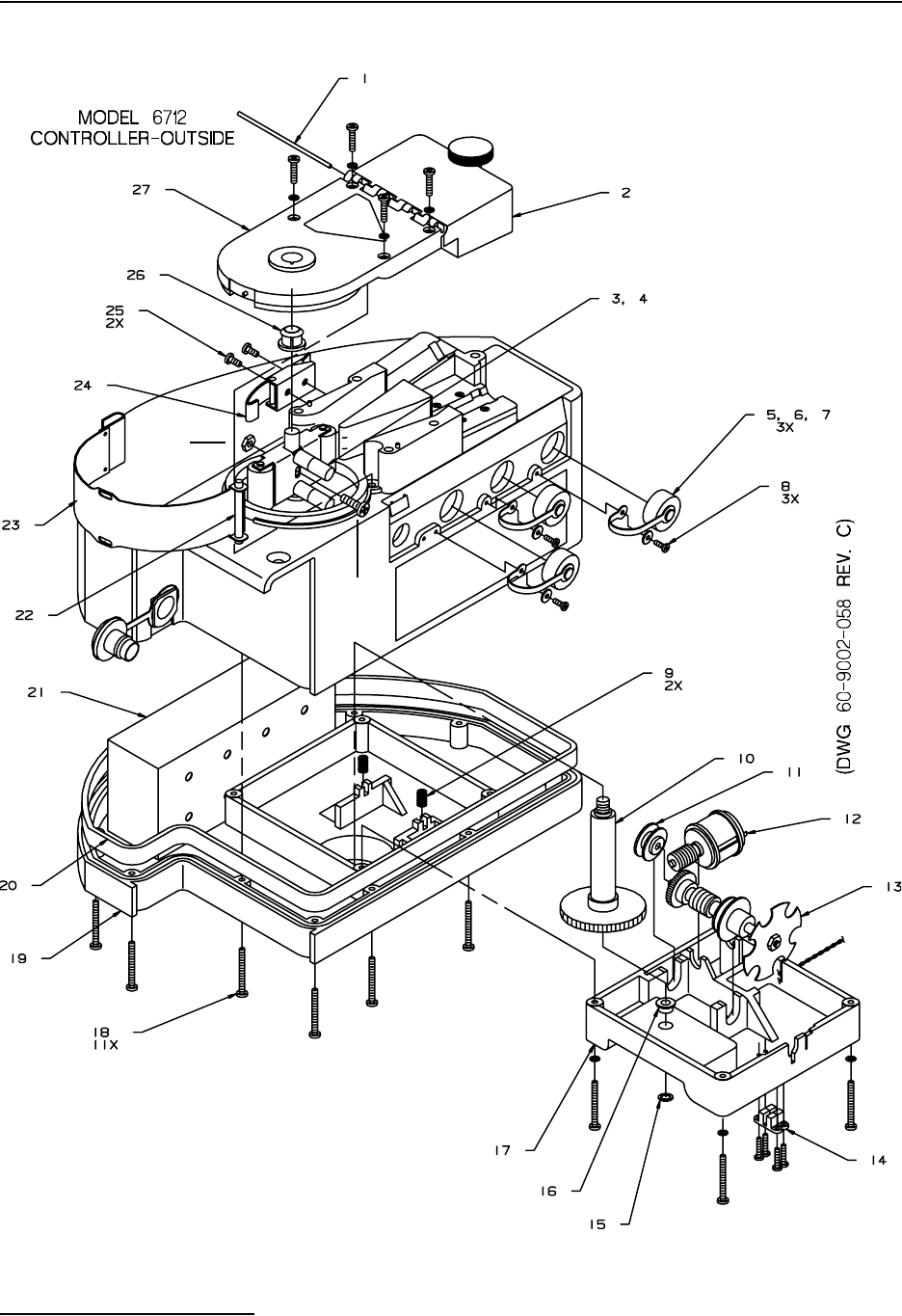
6712FR Refrigerated Sampler
Appendix D Replacement Parts List
D-6
Locknut,
10-32
Screw,
10-32 x
3/4
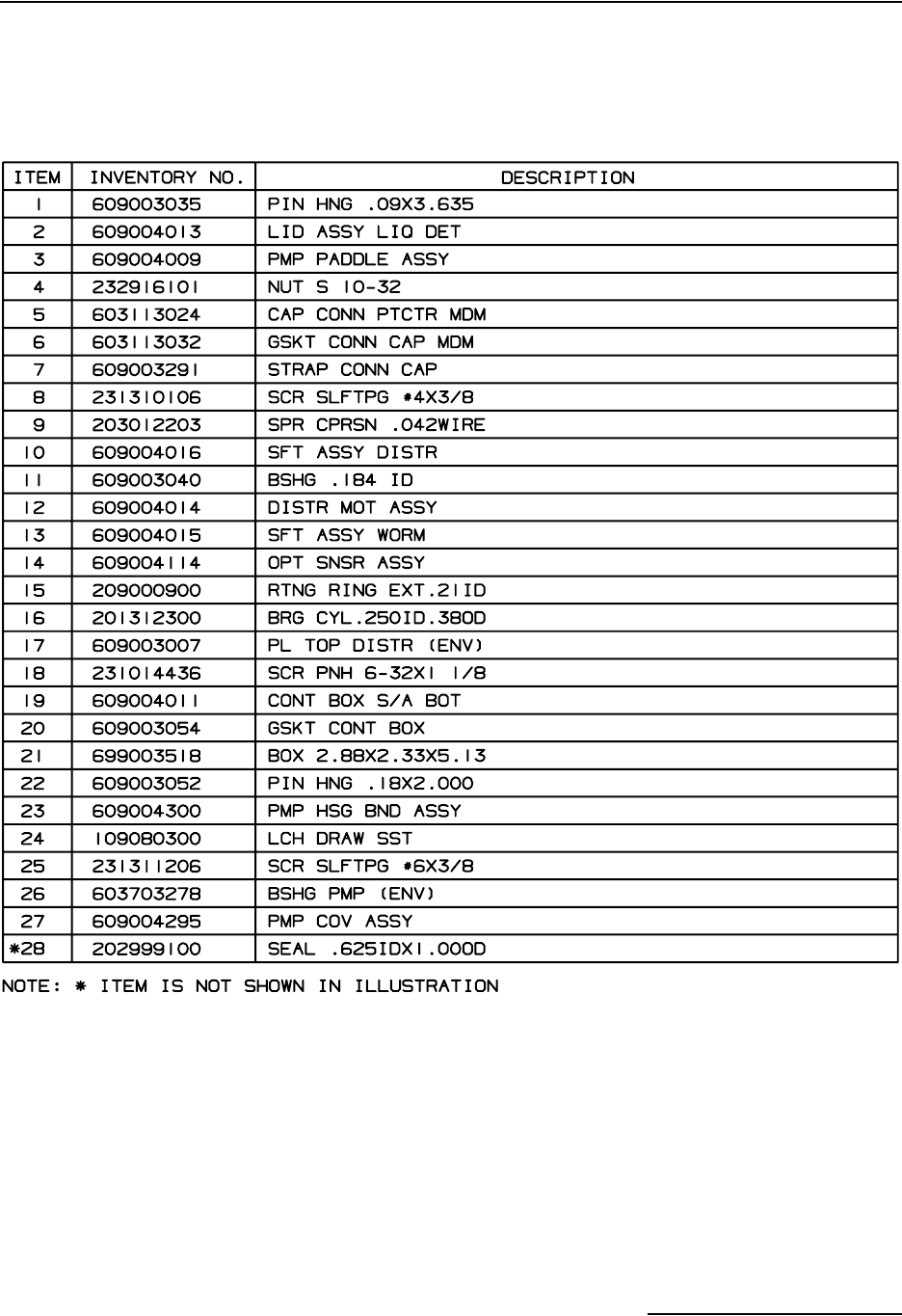
6712FR Refrigerated Sampler
Appendix D Replacement Parts List
D-7
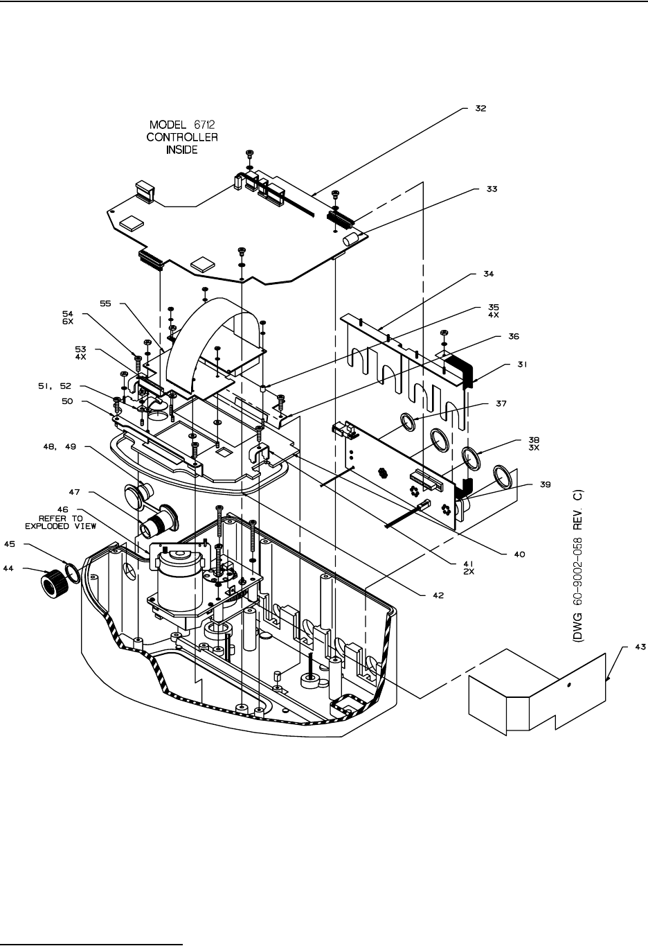
6712FR Refrigerated Sampler
Appendix D Replacement Parts List
D-8
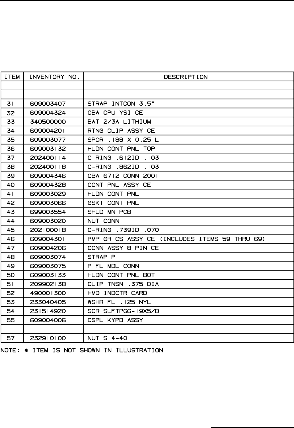
6712FR Refrigerated Sampler
Appendix D Replacement Parts List
D-9
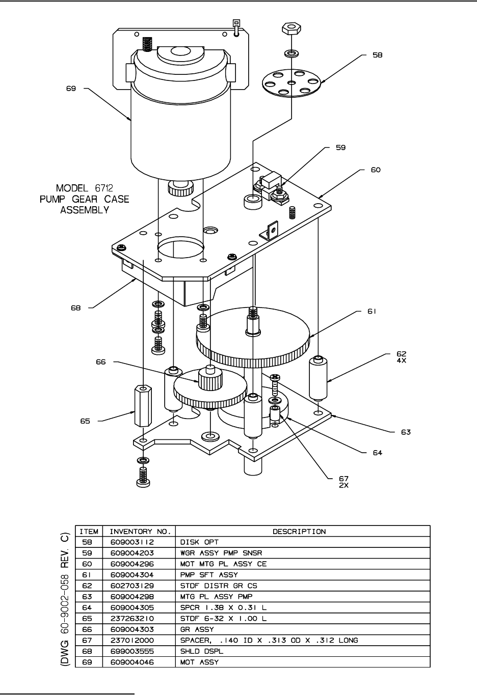
6712FR Refrigerated Sampler
Appendix D Replacement Parts List
D-10

E-1
6712FR Refrigerated Sampler
Appendix E Accessories List
E.1 Order Information Prices available on request. Additional items appear in
Appendix D, Replacement Parts. Many other items are available.
To order any item, contact your sales representative or the
factory. Note that the part name listed on your order acknowl-
edgment and invoice may be different than the item name listed
here. When examining these documents, use the part number for
reference.
E.2 Samplers
6712FR Refrigerated Sampler 120V . . . . . . . . . . . . . . . . . . . . . . . . . . . . . . . . . . . . . . . . . . . . . . . . . . . . .68-6710-072
(Includes controller, distributor arm, instruction manual and pocket guide.)
6712FR Refrigerated Sampler 230V . . . . . . . . . . . . . . . . . . . . . . . . . . . . . . . . . . . . . . . . . . . . . . . . . . . . .68-6710-073
(Includes controller, distributor arm, instruction manual and pocket guide.)
6712FR Refrigerated Sampler 120V with Temperature Logger. . . . . . . . . . . . . . . . . . . . . . . . . . . . . . . .68-6710-144
(Includes controller, distributor arm, instruction manual and pocket guide.)
6712FR Refrigerated Sampler 230V with Temperature Logger. . . . . . . . . . . . . . . . . . . . . . . . . . . . . . . .68-6710-145
(Includes controller, distributor arm, instruction manual and pocket guide.)
6712 Sampler Controller. . . . . . . . . . . . . . . . . . . . . . . . . . . . . . . . . . . . . . . . . . . . . . . . . . . . . . . . . . . . . . .68-6710-074
(Includes 2 Pump Tubes.)
6712 Samplers Pocket Guide . . . . . . . . . . . . . . . . . . . . . . . . . . . . . . . . . . . . . . . . . . . . . . . . . . . . . . . . . . .60-9003-589
6712FR Refrigerated Sampler Instruction Manual . . . . . . . . . . . . . . . . . . . . . . . . . . . . . . . . . .60-9003-590
E.3 Bottle Kits
24-Bottle Kit (350-milliliter glass bottles) . . . . . . . . . . . . . . . . . . . . . . . . . . . . . . . . . . . . . . . . . . . . . . . . .68-6700-033
(Includes bottles; bottle rack; configuration kit; and two discharge tubes).
24-Bottle Kit (1,000-milliliter polypropylene bottles) . . . . . . . . . . . . . . . . . . . . . . . . . . . . . . . . . . . . . . . .68-6700-032
(Includes bottles; bottle rack; configuration kit; and two discharge tubes).
12-Bottle Kit (2.5-liter polyethylene bottles) . . . . . . . . . . . . . . . . . . . . . . . . . . . . . . . . . . . . . . . . . . . . . . .68-6700-058
(Includes bottles; bottle rack; configuration kit; and two discharge tubes).
8-Bottle Kit (1.8-liter glass bottles) . . . . . . . . . . . . . . . . . . . . . . . . . . . . . . . . . . . . . . . . . . . . . . . . . . . . . .68-6700-035
(Includes bottles; bottle rack; configuration kit; and two discharge tubes).
Teledyne Isco, Inc.
P.O. Box 82531
Lincoln, NE 68501
Telephone Within U.S.A.
Toll free: (800) 228-4373
Outside U.S.A:(402) 464-0231
Fax: (402) 465-3022

6712FR Refrigerated Sampler
Appendix E Accessories List
E-2
8-Bottle Kit (2.0-liter polyethylene bottles) . . . . . . . . . . . . . . . . . . . . . . . . . . . . . . . . . . . . . . . . . . . . . . . .68-6700-034
(Includes bottles; bottle rack; configuration kit; and two discharge tubes).
2-Bottle Kit (7.5-liter polyethylene bottle) . . . . . . . . . . . . . . . . . . . . . . . . . . . . . . . . . . . . . . . . . . . . . . . . .68-6700-036
(Includes bottles, configuration kit and two discharge tubes).
2-Bottle Kit (9.4-liter glass bottles) . . . . . . . . . . . . . . . . . . . . . . . . . . . . . . . . . . . . . . . . . . . . . . . . . . . . . .68-6700-037
(Includes bottles; configuration kit and two discharge tubes).
1-Bottle Kit (9.4-liter polyethylene bottle) . . . . . . . . . . . . . . . . . . . . . . . . . . . . . . . . . . . . . . . . . . . . . . . . .68-6700-038
(Includes bottle; configuration kit; one unlined lid; 2 lids and two discharge tubes).
1-Bottle Kit (9.4-liter glass bottle) . . . . . . . . . . . . . . . . . . . . . . . . . . . . . . . . . . . . . . . . . . . . . . . . . . . . . . .68-6700-039
(Includes bottle; configuration kit; 2 lids and two discharge tubes).
1-Bottle Kit (15.0-liter polyethylene bottle) . . . . . . . . . . . . . . . . . . . . . . . . . . . . . . . . . . . . . . . . . . . . . . . .68-6700-040
(Includes bottle; configuration kit; 2 lids and two discharge tubes).
1-Bottle Kit (18.5-liter glass bottle) . . . . . . . . . . . . . . . . . . . . . . . . . . . . . . . . . . . . . . . . . . . . . . . . . . . . . .68-6700-042
(Includes bottle; configuration kit; 2 lids and two discharge tubes).
1-Bottle Kit (20.5-liter polyethylene bottle) . . . . . . . . . . . . . . . . . . . . . . . . . . . . . . . . . . . . . . . . . . . . . . . .68-6700-041
(Includes bottle; configuration kit; 2 lids and two discharge tubes).
E.4 Bottle Racks,
Retaining Rings,
Discharge Tubes,
Distributor Arm
Bottle Rack for 24-Bottle Kit (350-milliliter Glass Bottles and 8-Bottle Kits) . . . . . . . . . . . . . . . . . . . .60-2744-008
Bottle Rack for 24-Bottle Kit (1,000-milliliter Polypropylene Bottles). . . . . . . . . . . . . . . . . . . . . . . . . . .60-2744-007
Bottle Rack for 12-Bottle Kit . . . . . . . . . . . . . . . . . . . . . . . . . . . . . . . . . . . . . . . . . . . . . . . . . . . . . . . . . . .60-9004-151
Retaining Ring for 24-Bottle Kit (350-milliliter Glass Bottles) . . . . . . . . . . . . . . . . . . . . . . . . . . . . . . . .60-2724-020
Retaining Ring for 24-Bottle Kit (1,000-milliliter Polypropylene Bottles). . . . . . . . . . . . . . . . . . . . . . . .60-3703-058
Retaining Ring for 12-Bottle Kit. . . . . . . . . . . . . . . . . . . . . . . . . . . . . . . . . . . . . . . . . . . . . . . . . . . . . . . . .60-2903-127
8-Bottle Adaptor for 8-Bottle Rack. . . . . . . . . . . . . . . . . . . . . . . . . . . . . . . . . . . . . . . . . . . . . . . . . . . . . . .60-2743-024
Bottle Locating Base for 6700FR 2-Bottle Kits . . . . . . . . . . . . . . . . . . . . . . . . . . . . . . . . . . . . . . . . . . . .60-2723-102
Discharge Tube for 8-Bottle, 12-Bottle, and 24-Bottle Kits . . . . . . . . . . . . . . . . . . . . . . . . . . . . . . . . . . .60-9003-279
Discharge Tube for 2-Bottle Kits . . . . . . . . . . . . . . . . . . . . . . . . . . . . . . . . . . . . . . . . . . . . . . . . . . . . . . . .60-9003-283
Discharge Tube for 1-Bottle Kit (9.4-liter Polyethylene Bottle and
9400-milliliter Glass Bottle). . . . . . . . . . . . . . . . . . . . . . . . . . . . . . . . . . . . . . . . . . . . . . . . . . . . . . . . . .60-9003-262
Discharge Tube for 1-Bottle Kit (15.0-liter Polyethylene Bottle) . . . . . . . . . . . . . . . . . . . . . . . . . . . . . . .60-9003-264
Discharge Tube for 1-Bottle Kit (18.5-liter Glass Bottle and
20.5-liter Polyethylene Bottle) . . . . . . . . . . . . . . . . . . . . . . . . . . . . . . . . . . . . . . . . . . . . . . . . . . . . . . . .60-9003-266
Bulk Discharge Tube (10 foot Length) . . . . . . . . . . . . . . . . . . . . . . . . . . . . . . . . . . . . . . . . . . . . . . . . . . . .60-6700-046
Bulk Discharge Tube (50 foot Length) . . . . . . . . . . . . . . . . . . . . . . . . . . . . . . . . . . . . . . . . . . . . . . . . . . . .60-6700-047
Distributor Arm (includes nut) . . . . . . . . . . . . . . . . . . . . . . . . . . . . . . . . . . . . . . . . . . . . . . . . . . . . . . . . . .60-9004-050
E.5 Bulk Sets of Bottles
with Lids
Set of 24, 350-milliliter Glass Bottles with PTFE Lined Lids . . . . . . . . . . . . . . . . . . . . . . . . . . . . . . . . .68-2100-001
Set of 100, 350-milliliter Glass Bottles with PTFE Lined Lids . . . . . . . . . . . . . . . . . . . . . . . . . . . . . . . .68-3700-048
Set of 24, 1,000-milliliter Polypropylene Bottles with Polyethylene Foam Lined lids) . . . . . . . . . . . . . .68-2100-007
Set of 100, 1,000-milliliter Polypropylene Bottles with Polyethylene Foam Lined lids . . . . . . . . . . . . .68-3700-046
Set of 500, 1,000-milliliter Polypropylene Bottles with Polyethylene Foam Lined lids . . . . . . . . . . . . .68-3700-047
Set of 12, 2.5-liter Polyethylene Bottles with Lined Lids . . . . . . . . . . . . . . . . . . . . . . . . . . . . . . . . . . . . .68-6700-059
Set of 100, 2.5-liter Polyethylene Bottles with Lined Lids . . . . . . . . . . . . . . . . . . . . . . . . . . . . . . . . . . . .68-6700-060
Set of 8, 1.8-liter Glass Bottles with PTFE Lined Lids . . . . . . . . . . . . . . . . . . . . . . . . . . . . . . . . . . . . . .68-2740-027

6712FR Refrigerated Sampler
Appendix E Accessories List
E-3
Set of 100, 1.8-liter Glass Bottles with PTFE Lined Lids . . . . . . . . . . . . . . . . . . . . . . . . . . . . . . . . . . . .68-3720-030
Set of 8, 2.0-liter Polyethylene Bottle with Unlined Lids . . . . . . . . . . . . . . . . . . . . . . . . . . . . . . . . . . . . .68-2740-026
Set of 100, 2.0-liter Polyethylene Bottle with Unlined Lids . . . . . . . . . . . . . . . . . . . . . . . . . . . . . . . . . . .68-3720-028
7.5-liter Polyethylene Bottle . . . . . . . . . . . . . . . . . . . . . . . . . . . . . . . . . . . . . . . . . . . . . . . . . . . . . . . . . . . .299-0013-07
9.4-liter (21/2-gallon) Glass Bottle with Two PTFE Lined Lids. . . . . . . . . . . . . . . . . . . . . . . . . . . . . . . . .68-2930-006
9.4-liter (21/2-gallon) Polyethylene Bottle with Two Unlined Lid . . . . . . . . . . . . . . . . . . . . . . . . . . . . . . .68-2740-009
15.0-liter (4-gallon) Polyethylene Bottle with Two Unlined Lids . . . . . . . . . . . . . . . . . . . . . . . . . . . . . . .68-2930-004
18.5-liter (5 gallon) Glass Bottle with Two PTFE lined Lids . . . . . . . . . . . . . . . . . . . . . . . . . . . . . . . . . .68-6700-057
20.5-liter (51/2-gallon) Polyethylene Bottle with Two Unlined Lids . . . . . . . . . . . . . . . . . . . . . . . . . . . . .68-2930-005
E.6 Pump Tubes, Suction
Line, Strainers
Pump Tube (Qty 5) . . . . . . . . . . . . . . . . . . . . . . . . . . . . . . . . . . . . . . . . . . . . . . . . . . . . . . . . . . . . . . . . . . .68-6700-062
Pump Tube (Qty 10) . . . . . . . . . . . . . . . . . . . . . . . . . . . . . . . . . . . . . . . . . . . . . . . . . . . . . . . . . . . . . . . . . .68-6700-044
Pump Tube (Qty 25) . . . . . . . . . . . . . . . . . . . . . . . . . . . . . . . . . . . . . . . . . . . . . . . . . . . . . . . . . . . . . . . . . .68-6700-045
3/8-inch Standard Weighted Polypropylene Strainer with 10 foot Suction Line . . . . . . . . . . . . . . . . . . .60-9004-378
3/8-inch Standard Weighted Polypropylene Strainer with 25 foot Suction Line . . . . . . . . . . . . . . . . . . .60-9004-379
PTFE Suction Line (10 foot length) . . . . . . . . . . . . . . . . . . . . . . . . . . . . . . . . . . . . . . . . . . . . . . . . . . . . . .60-1683-146
PTFE Suction Line (25 foot length) . . . . . . . . . . . . . . . . . . . . . . . . . . . . . . . . . . . . . . . . . . . . . . . . . . . . . .60-2703-114
Bulk Vinyl Suction Line (100 foot length) . . . . . . . . . . . . . . . . . . . . . . . . . . . . . . . . . . . . . . . . . . . . . . . . .68-1680-058
Bulk Vinyl Suction Line (500 foot length) . . . . . . . . . . . . . . . . . . . . . . . . . . . . . . . . . . . . . . . . . . . . . . . . .68-1680-059
3/8-inch Vinyl Suction Line Accessory Kit (includes tube coupling, clamp, and instructions) . . . . . . . .68-3700-007
3/8-inch Standard Weighted Polypropylene Strainer. . . . . . . . . . . . . . . . . . . . . . . . . . . . . . . . . . . . . . . . .60-9004-367
CPVC Weighted Plastic-Coated Strainer . . . . . . . . . . . . . . . . . . . . . . . . . . . . . . . . . . . . . . . . . . . . . . . . . .60-3704-066
3/8-inch Stainless Steel Low Flow Strainer Only. . . . . . . . . . . . . . . . . . . . . . . . . . . . . . . . . . . . . . . . . . . .69-2903-138
3/8-inch Suction Line Tubing Coupler . . . . . . . . . . . . . . . . . . . . . . . . . . . . . . . . . . . . . . . . . . . . . . . . . . . .69-4703-106
E.7 Data Collection
Devices and Cables
581 Rapid Transfer Device (RTD) . . . . . . . . . . . . . . . . . . . . . . . . . . . . . . . . . . . . . . . . . . . . . . . . . . . . . . .60-9004-027
Power Cable 581 Rapid Transfer Device (RTD). . . . . . . . . . . . . . . . . . . . . . . . . . . . . . . . . . . . . . . . . . . . .60-9004-077
Flowlink 4® for Windows Software – New License. . . . . . . . . . . . . . . . . . . . . . . . . . . . . . . . . . . . . . . . . .60-2544-058
Flowlink 4® for Windows Software – Upgrade . . . . . . . . . . . . . . . . . . . . . . . . . . . . . . . . . . . . . . . . . . . . .60-2544-048
SAMPLINK Software (Includes Instruction Manual) . . . . . . . . . . . . . . . . . . . . . . . . . . . . . . . . . . . . . . . .60-3774-013
Computer Connect Cable (25-pin) . . . . . . . . . . . . . . . . . . . . . . . . . . . . . . . . . . . . . . . . . . . . . . . . . . . . . . .60-2544-040
Computer Connect Cable (9-pin) . . . . . . . . . . . . . . . . . . . . . . . . . . . . . . . . . . . . . . . . . . . . . . . . . . . . . . . .60-2544-044
Connector to Attach Non-Isco Flow Meter to Customer Supplied Cable . . . . . . . . . . . . . . . . . . . . . . . . .68-1680-060
Serial Output Connect Cable (for use with the periodic serial output feature). . . . . . . . . . . . . . . . . . . .60-9004-263
External 12-volt DC Power Cable. . . . . . . . . . . . . . . . . . . . . . . . . . . . . . . . . . . . . . . . . . . . . . . . . . . . . . . .60-1394-023
Flow Meter-to-Two Samplers Cable . . . . . . . . . . . . . . . . . . . . . . . . . . . . . . . . . . . . . . . . . . . . . . . . . . . . . .60-3004-018
Dual Sampler Mode Interconnect Cable . . . . . . . . . . . . . . . . . . . . . . . . . . . . . . . . . . . . . . . . . . . . . . . . . .60-3704-065
Dual Sampler Mode-to-Flow Meter Cable . . . . . . . . . . . . . . . . . . . . . . . . . . . . . . . . . . . . . . . . . . . . . . . . .60-3704-080
Non-Isco Flow Meter-to-Sampler Cable . . . . . . . . . . . . . . . . . . . . . . . . . . . . . . . . . . . . . . . . . . . . . . . . . . .60-1394-077
Sampler to Flow Meter /1640 Liquid Level Actuator “Y” Cable . . . . . . . . . . . . . . . . . . . . . . . . . . . . . . . .60-3004-019
Sampler to Flow Meter Cable . . . . . . . . . . . . . . . . . . . . . . . . . . . . . . . . . . . . . . . . . . . . . . . . . . . . . . . . . . .60-3004-107
2100 Series Sampler Interface Cable . . . . . . . . . . . . . . . . . . . . . . . . . . . . . . . . . . . . . . . . . . . . . . . . . . . . .60-2004-260
Solar Panel “Y” Cable . . . . . . . . . . . . . . . . . . . . . . . . . . . . . . . . . . . . . . . . . . . . . . . . . . . . . . . . . . . . . . . . .60-3004-098
Solar Panel/Interrogator. Extension Cable . . . . . . . . . . . . . . . . . . . . . . . . . . . . . . . . . . . . . . . . . . . . . . . .60-2544-028

6712FR Refrigerated Sampler
Appendix E Accessories List
E-4
Solar Panel Cable (25 foot length) . . . . . . . . . . . . . . . . . . . . . . . . . . . . . . . . . . . . . . . . . . . . . . . . . . . . . . .60-3004-097
Rain Gauge/Refrigerator Temperature Sensor “Y” cable . . . . . . . . . . . . . . . . . . . . . . . . . . . . . . . . . . . . .60-9004-294
4200T Modem . . . . . . . . . . . . . . . . . . . . . . . . . . . . . . . . . . . . . . . . . . . . . . . . . . . . . . . . . . . . . . . . . . . factory installed
Contact your sales representative or Teledyne Isco Customer Service.
Note
The modem is disabled when an interrogator cable is con-
nected to the sampler’s interrogator port. It cannot receive
incoming calls, and the alarm dialout will be rendered inopera-
tive, while this cable is connected. Disconnect the interroga-
tor cable in order to use the 4200T modem.
CDMA Digital Cellular Modem . . . . . . . . . . . . . . . . . . . . . . . . . . . . . . . . . . . . . . . . . . . . . . . . . . . . . . . . .60-5314-489
GSM Digital Cellular Modem . . . . . . . . . . . . . . . . . . . . . . . . . . . . . . . . . . . . . . . . . . . . . . . . . . . . . . . . . . .60-5314-563
(Requires the purchase of a SIM card from your preferred provider.)
E.8 12-Volt Power Sources
913 High Capacity Power Pack (120-volt) . . . . . . . . . . . . . . . . . . . . . . . . . . . . . . . . . . . . . . . . . . . . . . . . .60-1684-088
914 Battery-Backed Power Pack (120-volt) . . . . . . . . . . . . . . . . . . . . . . . . . . . . . . . . . . . . . . . . . . . . . . . .60-3004-130
921 Nickel-Cadmium Battery . . . . . . . . . . . . . . . . . . . . . . . . . . . . . . . . . . . . . . . . . . . . . . . . . . . . . . . . . . .60-1684-040
923 High Capacity Power Pack (240-volt) . . . . . . . . . . . . . . . . . . . . . . . . . . . . . . . . . . . . . . . . . . . . . . . . .60-1684-093
924 Battery-Backed Power Pack (240-volt) . . . . . . . . . . . . . . . . . . . . . . . . . . . . . . . . . . . . . . . . . . . . . . . .60-3004-160
947 Lead-Acid Battery . . . . . . . . . . . . . . . . . . . . . . . . . . . . . . . . . . . . . . . . . . . . . . . . . . . . . . . . . . . . . . . .60-3004-106
Manual Body - Power Products Guide . . . . . . . . . . . . . . . . . . . . . . . . . . . . . . . . . . . . . . . . . . . . . . . . . . . .60-9003-092
E.9 Modules, Rain Gauges,
& Interfacing
Instruments
(Note: Additional accessories for modules and interfacing instruments appear in the accessories list at the back of
the manual for each module or instrument.)
701 pH Module with Double Junction pH Sensor with Temperature Sensor . . . . . . . . . . . . . . . . . . . . .68-6700-052
710 Ultrasonic Flow Module . . . . . . . . . . . . . . . . . . . . . . . . . . . . . . . . . . . . . . . . . . . . . . . . . . . . . . . . . . . .68-6700-049
720 Submerged Probe Module, 10 ft range . . . . . . . . . . . . . . . . . . . . . . . . . . . . . . . . . . . . . . . . . . . . . . . .68-6700-068
730 Bubbler Flow Module . . . . . . . . . . . . . . . . . . . . . . . . . . . . . . . . . . . . . . . . . . . . . . . . . . . . . . . . . . . . . .68-6700-050
780 Analog Interface Module . . . . . . . . . . . . . . . . . . . . . . . . . . . . . . . . . . . . . . . . . . . . . . . . . . . . . . . . . . .60-9004-040
675 Rain Gauge . . . . . . . . . . . . . . . . . . . . . . . . . . . . . . . . . . . . . . . . . . . . . . . . . . . . . . . . . . . . . . . . . . . . . .60-3284-013
1640 Liquid Level Actuator . . . . . . . . . . . . . . . . . . . . . . . . . . . . . . . . . . . . . . . . . . . . . . . . . . . . . . . . . . . .60-1644-000
4-20 mA Sampler Input Interface. . . . . . . . . . . . . . . . . . . . . . . . . . . . . . . . . . . . . . . . . . . . . . . . . . . . . . . .60-3704-075
Refrigerator Temperature Sensor with 5 ft (1.55 m) cable . . . . . . . . . . . . . . . . . . . . . . . . . . . . . . . . . . . .68-6700-136
Internal 3-channel 4-20 mA programmable output
for 6700 Series sampler. Includes multi-analog output cable, 10 ft.. . . . . . . . . . . . . . . . . . . . . . . .60-9004-266
E.10 SDI-12 Data
Acquisition Connect
Cables
Note: Y-connect cables can be combined with other Y-connect cables or SDI-12 adapter cables if multiple SDI-12
devices are to be connected.
Rain Gauge Y-Connect Cable . . . . . . . . . . . . . . . . . . . . . . . . . . . . . . . . . . . . . . . . . . . . . . . . . . . . . . . . . . .60-9004-294
(This cable allows connection of 2 of the following: rain gauge, SDI-12 adapter cable, SDI-12 Y-connect cable,
I/O adapter, temperature sensor.)

6712FR Refrigerated Sampler
Appendix E Accessories List
E-5
YSI SDI-12 Adapter Cable . . . . . . . . . . . . . . . . . . . . . . . . . . . . . . . . . . . . . . . . . . . . . . . . . . . . . . . . . . . . .60-9004-337
YSI SDI-12 Y-Connect Cable. . . . . . . . . . . . . . . . . . . . . . . . . . . . . . . . . . . . . . . . . . . . . . . . . . . . . . . . . . . .60-9004-338
(This cable allows connection of a YSI SDI-12 sonde and an Isco Rain Gauge.)
Hydrolab Quanta SDI-12 Adapter Cable . . . . . . . . . . . . . . . . . . . . . . . . . . . . . . . . . . . . . . . . . . . . . . . . . .60-9004-339
Hydrolab Quanta SDI-12 Y-Connect Cable . . . . . . . . . . . . . . . . . . . . . . . . . . . . . . . . . . . . . . . . . . . . . . . .60-9004-340
(This cable allows connection of a Hydrolab Quanta SDI-12 sonde and an Isco Rain Gauge.)
SDI-12 Adapter Cable (6 foot length, no connector) . . . . . . . . . . . . . . . . . . . . . . . . . . . . . . . . . . . . . . . . .60-9004-341
(This is for use with a customer supplied connector to an SDI-12 device.)
SDI-12 Y-Connect Cable (6 foot length, no connector). . . . . . . . . . . . . . . . . . . . . . . . . . . . . . . . . . . . . . . .60-9004-342
(This is for use with a customer supplied connector to an SDI-12 device and an Isco Rain Gauge.)

6712FR Refrigerated Sampler
Appendix E Accessories List
E-6

Index-1
6712FR Refrigerated Sampler
Index
A
Accessories
bottle racks E-2
bulk bottles E-2
bulk discharge tubing E-3
cables E-3
data collection accessories E-3
power sources and battery chargers E-4
pump tube E-3
refrigerator temperature sensor E-4
retaining rings E-2
strainers E-3
suction line E-3
acknowledge dialout alarm 5-40
alarm acknowledgement 5-40
alarms 5-39
Alkaline battery
battery warning 8-14
opening controller case 8-12
replacing 8-14
Analog output 5-41
analog output 5-41
B
Backlighting 5-30
Bottle kits
installing 2-4
Bottle Number Signal 5-31
Bottles-per-sample distribution 4-6, 5-16
C
Cables
Master/Slave-to-Flow-Meter Cable 5-29
Calendar 3-5
setting clock and calendar 3-6, 8-5
Calibration
during a manual pause 4-13
sample volumes 4-14
Cleaning protocols 8-3
Clock
setting clock and calendar 3-6, 8-5
Clock start-time menu 3-6
Combined results report
see Sampling reports
Compatible Isco products 1-4
Computer control 7-1
checksum validation 7-8
external program control 7-4
menu control 7-2
remote keypad 7-8
sampling reports 7-3
Configuring reports 4-19
Construction
compact and standard sampler 1-7
Continuous sampling 2-14, 4-6, 5-17
Controller
mounting on refrigerator 2-1
Count Switched Distribution
Sampler Enable 5-22
D
Data collection accessories
accessories list E-3
Desiccant
opening controller case 8-12
Diagnostic tests
distributor test 8-9
Diagnostics 8-7
Dialout alarms 4-18, 5-39
dialout alarms 5-39
Display Backlighting 5-30
Distribution 4-6, 5-16
bottles-per-sample distribution 4-6, 5-16
continuous sampling 4-6, 5-17
count-switched distribution 5-16
event pacing 5-12
multiple-bottle compositing 5-16
random-interval pacing 5-15
Samples per bottle 4-6, 5-16
sequential distribution 4-6, 5-16
time-switched distribution 5-16
Dual sampler mode 5-29
E
Enable
see Sampler enable
Error messages 8-16
Event marks 5-30
3-second pulse 5-31
master/slave sampling 5-29
timing diagram 5-31
variable-duration pulse 5-31
Event pacing 5-12
Extended programming
extended programming features 1-6–??
one-part and two-part programs 5-1
showing extended screens 3-3, 4-1, 5-1
F
First valid day 4-8
Flow pacing 4-5
Flow proportional sample volumes 5-19
G
Grab samples 4-13, 4-14
H
hardware
analog output 5-41
cellular modems 5-40
dialout alarms 5-39

6712FR Refrigerated Sampler
Index
Index-2
I/O pin programming 5-37
pager numbers 5-40
rain gauge 5-36
refrigerator temperature 5-41
sonde 5-36
Hardware set-up
master/slave sampling 5-29
hardware setup 5-36
I
I/O pin programming 5-37
Installing
locating base for 2-bottle kit 2-6
suction line 2-10, 2-11
Interrupting
interrupting a running program 4-12
manual paused operation 4-12
L
Line rinses 5-12
Liquid detector enable/disable 5-28
Locating base
2-bottle kit 2-6
M
Maintenance
alkaline battery 8-14
checklist 8-9
cleaning
guidelines 8-1
protocols for bottles and tubing 8-3
maintenance programming screens 8-4
diagnostics 8-7
pump counts for pump tube warning 8-9
pump tube alarm 8-9
reinitializing 8-9
opening controller case 8-12
pump tube 8-9
servicing the refrigerator
electrical system 8-17
refrigeration system 8-20
Manual functions 4-14
calibrate volume 4-14
grab samples 4-14
moving distributor 4-17
running pump manually 4-17
Manual paused operation 4-12–??
Master/slave sampling 5-29
event marks 5-29
sampler enable 5-29
Master/Slave-to-Flow-Meter Cable 5-29
Materials
used in sampler construction 1-7
Memory 1-4, 5-42
capacity 1-2, 5-43
creating partitions 5-42
data-storage interval 5-42
partition sizes 5-42
roll-over 5-43
sampling results 5-42
stored data will be lost! 5-1
triggered 5-43
Menu screens 3-3
Modem 7-9
Module summary report
see Sampling reports
Modules
700 Series Modules 1-2
displayed readings 4-11
Multiple-bottle compositing 5-16
N
Nonuniform time pacing 5-15
O
One-part programs 5-1
Operating
running sampling programs 4-10, 5-27
Other Functions
see Hardware setup 4-14, 5-28
see Maintenance 4-14, 5-28
see Manual functions 4-14, 5-28
see Programming Style 4-14, 5-28
P
Pacing 4-5, 5-12
event pacing 5-12
flow pacing 4-5
nonuniform clock-time pacing 5-15
nonuniform time pacing 5-15
random-interval pacing 5-15
time pacing 4-5, 5-12
Partitions
creating 5-42
Pause and resume 5-27
Periodic serial output 5-39
Power sources
accessories list E-4
Presample purge
event marks 5-31
Program name menu
how to use 3-7
Program settings report
see Sampling reports
Program storage
see Stored programs
Program Style 3-4
Programming
changing program name 3-8
changing site description 3-8
clock and calendar 3-5
extended programming features 1-6–??
menu screens 3-3
program name menu 3-7
running programs 4-10, 5-27
site description menu 3-7
text entry 3-7
Pump
running pump manually 4-17
Pump Counts
pump tube warning 8-9
Pump counts
purging a nonstandard suction line 5-31
Pump tube
accessories list E-3
replacing 8-9
warning 8-5
Q
Quick View Screens 3-4
see Program Style

6712FR Refrigerated Sampler
Index
Index-3
R
rain gauge setup 5-36
Random-interval pacing 5-15
refrigerator temperature 5-41
Refrigerator temperature sensor 5-41, E-4
Reinitialize controller
effects on stored programs 8-9
Remote access
computer commands 7-1
telephone commands 7-9
Replacing internal alkaline battery 8-14
Resume 5-27
Retries 5-12
Rinses 5-12
RS-232 communications 7-1
Running programs 4-10, 5-27
S
Sample volume
calibrating 4-14
flow proportional 5-19
measuring 2-10
variable volume sampling 5-19
Sampler enable 4-9, 5-22
"dry period" option 5-26
master/slave sampling 5-29
repeatable enable 5-25
sample at enable or disable 5-25
start delay 5-26
start times 4-8
stay enabled 5-25
Samples per bottle 4-6, 5-16
Sampling cycle 2-9
Sampling programs
running programs 4-10, 5-27
Sampling reports
Collecting reports 4-18, 5-28
configuring 4-19
sampling results report 4-20
Viewing 4-18
Sampling results report
see Sampling reports
Sampling retries 5-12
Sequential distribution 4-6, 5-16
Serial output 5-39, 7-6
Servicing 2-14
service schedule 2-14
Site description menu
how to use 3-7
sonde setup 5-36
Start times
clock start-time menu 3-6
event pacing 5-12
first valid day 4-8, 5-27
sampler enable 4-8
Stored data 5-1
Stored programs 5-2
effects of reinitializing controller to factory
settings 8-9
selecting a program 5-2
Stormwater monitoring
Two-part programs 5-2
Strainers
accessories list E-3
selecting 2-8
Suction head
auto suction head 5-12
automatic determination 5-12
manual (ENTER HEAD) settings 5-12
variations in pump counts for fluctuating heads
4-20
Suction line
accessories list E-3
attaching to pump tube 2-7
installing and routing 2-10
measuring and cutting 2-7
System IDs 4-18
T
Technical specifications
refrigerator ??–1-13
Telephone commands 7-9
Text entry
numbers 3-3
program names 3-7
site descriptions 3-7
text messaging 5-40
Time pacing 4-5, 5-12
Times and dates
entering times and dates 3-5
Time-switched distribution 5-16
pause and resume 5-27
Tube coupling
attaching suction line 2-6
Two-part programs 5-1
storm-water monitoring 5-2
V
Variable volume sampling 5-19
Variable-duration pulse 5-31
event marks 5-31
Voice modem 7-9
W
Warning
warning messages 8-16
Y
YSI 600
about the sonde 1-2
displayed readings 4-11

6712FR Refrigerated Sampler
Index
Index-4

Compliance Statements
Hazmat Table FR/CR 60-9003-654 Rev.
ℶ❐₼㦘㹡㦘⹂䓸德㒥⏒侯䤓⚜䱿♙⚺摞
Name and amount of Hazardous Substances or Elements in the product
᳝↦᳝ᆇ⠽䋼ܗ㋴
Hazardous Substances or Elements
捷ↅ⚜䱿
Component Name 䪙
(Pb)
∲
(Hg)
䬝
(Cd)
݁Ӌ䫀
(Cr(VI))
⒈㘨㣃
(PBB)
⒈Ѡ㘨㣃
(PBDE)
兎恾㨎
Circuit Boards X O O O O O
㣍䯉
Display X O O O O O
㘴兎
Wiring O O O O X O
␔捷䟄冕
Internal Cables O O O O X O
☚冸㧉
Compressor O O O O X O
公冧᧨公䍼
Insulation O O O O X O
䟄䄟兎
Line Cord O O O O X O
䟄䄟
Power Supply X O O O X O
䦃㿐䟄㧉
DC Motor X O O O X O
⺞枽䥧
Keypad O O O O X O
㘴⯃
Connectors O O X O O O
ℶ❐₼㦘㹡㦘⹂䓸德㒥⏒侯䤓⚜䱿♙⚺摞᧶Name and amount of Hazardous Substances or Elements in
the product
O: 嫷䯉年㦘㹡㦘⹂䓸德⦷年捷ↅ㓏㦘⧖德㧟㠨₼䤓⚺摞⧖⦷ST/ 㪖屓⸩䤓棟摞尐㻑ⅴₚᇭ
O: Represent the concentration of the hazardous substance in this component’s any homogeneous pieces is
lower than the ST/ standard limitation.
X᧶嫷䯉年㦘㹡㦘⹂䓸德咂⺠⦷年捷ↅ䤓㩟⧖德㧟㠨₼䤓⚺摞怔⒉ST/ 㪖屓⸩䤓棟摞尐㻑ᇭ
(←₩♾⦷㷳⮓᧨㫈㗽⸭棔㍔⑄⺈ₙ嫷₼㓢“X” 䤓㔏㦾☮⥯扪嫛扪㷴広㢝ᇭ)
X: Represent the concentration of the hazardous substance in this component’s at least one homogeneous
piece is higher than the ST/ standard limitation.
(Manufacturer may give technical reasons to the “X”marks)
䘾≬∎䞷㦮䟀兞洛䫽⸩ᇭ
The Environmentally Friendly Use Period (EFUP) was determined through experience.
䞮ℶ㡴㦮嬺冥䪐⦷侊⒦⚆䪐₼ᇭⓜₘ⇜㟿ⷦ䞮ℶ(207 ⅲ嫷 2007 )ᇭ椞⚝䤓₹ⷦ㹜ⅲ嫷㦗᧶
A㦗᧨Bℛ㦗᧨䷘䷘ᇭ
The date of Manufacture is in code within the serial number. The first three numbers are the year of
manufacture (207 is year 2007) followed by a letter for the month. "A" is January, "B" is February and so on.
CE Declaration of Conformity
DECLARATION OF CONFORMITY
Application of Council Directive: 89/336/EEC – The EMC Directive
73/23/EEC – The Low Voltage Directive
Manufacturer's Name: Teledyne Isco, Inc.
Manufacturer's Address: 4700 Superior, Lincoln, Nebraska 68504 USA
Mailing Address: P.O. Box 82531, Lincoln, NE 68501
Equipment Type/Environment: Laboratory Equipment for Light Industrial/Commercial Environments
Trade Name/Model No: 4200T Modem
Year of Issue: 2001
Standards to which Conformity is Declared: EN 55024-1998 EMC Requirements for Information Technology Equipment
EN 60950 Safety Requirements for Information Technology Equipment
FCC Part 68
Standard Description Severity Applied Performance Criteria
EN61000-4-2 Electrostatic Discharge Level 2 - 4kV contact discharge
Level 3 - 8kV air discharge
B
B
EN61000-4-3 Radiated RF Immunity 80 MHz to 1000MHz 80% AM at 1kHz
Level 1 – 10V/m
A
EN61000-4-4 Electrical Fast Transient Level 2 - 2kV on ac lines B
EN61000-4-5 Surge on AC Lines 2kV common mode,
1kV differential mode
B
EN61000-4-6 Conducted RF on AC lines 150 kHz to 80 MHz,
3V rms, 80% modulated
B
EN61000-4-11 Voltage Dips/Short Interruptions 0.5 cycle, each polarity/100% B
EN 55022 RF Emissions Group 1, Class A, Information Technology
Equipment
EN61000-3-2, 3-3 Harmonic, Flicker
We, the undersigned, hereby declare that the design of the equipment specified above conforms to the above Directive(s) and
Standards as of July 5, 2001.
William Foster
USA Representative
William Foster
Director of Engineering
Teledyne Isco, Inc.
4700 Superior Street
Lincoln, Nebraska 68504
Phone: (402) 464-0231
Fax: (402) 464-4543
60-3212-049
Rev. A
CE Declaration of Conformity
DECLARATION OF CONFORMITY
Application of Council Directive: 89/336/EEC – The EMC Directive
73/23/EEC – The Low Voltage Directive
Manufacturer's Name: Teledyne Isco, Inc.
Manufacturer's Address: 4700 Superior, Lincoln, Nebraska 68504 USA
Mailing Address: P.O. Box 82531, Lincoln, NE 68501
Equipment Type/Environment: Laboratory Equipment for Light Industrial/Commercial Environments
Trade Name/Model No: 6712FR Refrigerated Sampler
Year of Issue: 2001
Standards to which Conformity is Declared: EN 61010-1 Safety Requirements for Electrical Equipment for
Measurement, Control, and Laboratory Use
EN 61326:1998 EMC Requirements for Electrical Equipment for Measurement,
Control, and Laboratory Use
EN60529 Degrees of Protection Provided by the Enclosure IP-26
Standard Description Severity Applied Performance Criteria
EN61000-4-2 Electrostatic Discharge Level 2 - 4kV contact discharge
Level 3 - 8kV air discharge
A
EN61000-4-3 Radiated RF Immunity 80 MHz to 1000MHz 80% AM at 1kHz
Level 1 – 10V/m
A
EN61000-4-4 Electrical Fast Transient Level 2 – 2kV on AC lines A
EN61000-4-5 Surge on I/O Lines 2kV common mode, 1KV
differential mode
A
EN61000-4-6 Conducted RF on AC lines 150 kHz to 80 MHz, 3V rms,
80% modulated
A
EN61000-4-11 Voltage Dips/Short Interruptions 0.5 cycle, each polarity/100% A
CISPR11/
EN 55011
RF Emissions Group 1, Class A Industrial, Scientific, and
Medical Equipment
EN61000-3-2, 3-3 Harmonic, Flicker
We, the undersigned, hereby declare that the design of the equipment specified above conforms to the above Directive(s) and
Standards as of March 6, 2001
Wiliam Foster
USA Representative
William Foster
Director of Engineering
Teledyne Isco, Inc.
4700 Superior Street
Lincoln, Nebraska 68504
Phone: (402) 464-0231
Fax: (402) 464-4543
60-9002-072
Rev B
War ra nt y

Teledyne Isco One Year
Limited Factory Service Warranty *
Teledyne Isco warrants covered products
against failure due to faulty parts or
workmanship for a period of one year (365
days) from their shipping date, or from the
date of installation by an authorized Teledyne
Isco Service Engineer, as may be appropriate.
This warranty does not cover loss, damage,
or defects resulting from transportation
between the customer’s facility and the repair
facility.
Teledyne Isco specifically disclaims any
warranty of merchantability or fitness for a
particular purpose.During the warranty period, repairs,
replacements, and labor shall be provided at
no charge. Teledyne Isco’s liability is strictly
limited to repair and/or replacement, at
Teledyne Isco’s sole discretion.
This warranty applies only to products sold
under the Teledyne Isco trademark and is
made in lieu of any other warranty, written or
expressed.
Failure of expendable items (e.g., charts,
ribbon, tubing, lamps, glassware, seals,
filters, fittings, and wetted parts of valves), or
from normal wear, accident, misuse,
corrosion, or lack of proper maintenance, is
not covered. Teledyne Isco assumes no
liability for any consequential damages.
No items may be returned for warranty
service without a return authorization number
issued from Teledyne Isco.
The warrantor is Teledyne Isco, Inc.
4700 Superior, Lincoln, NE 68504, U.S.A.
* This warranty applies to the USA and countries where Teledyne Isco Inc. does not have an authorized dealer. Custo mers in countries outside
the USA, where Teledyne Isco has an authorized dealer, should contact their Teledyne Is co dealer for warranty service.
In the event of instrument problems, always contact the Teledyne Isco Service Department, as problems can
often be diagnosed and corrected without requiring an on-site visit. In the U.S.A., contact Teledyne Isco Service
at the numbers listed below. International customers should contact their local Teledyne Isco agent or Teledyne
Isco International Customer Service.
Return Authorization
A return authorization number must be issued prior to shipping. Following authorization,
Teledyne Isco will pay for surface transportation (excluding packing/crating) both ways for 30
days from the beginning of the warranty period. After 30 days, expense for warranty shipments
will be the responsibility of the customer.
Shipping Address: Teledyne Isco, Inc. - Attention Repair Service
4700 Superior Street
Lincoln NE 68504 USA
Mailing address: Teledyne Isco, Inc.
PO Box 82531
Lincoln NE 68501 USA
Phone: Technical Support
(800)775-2965 (lab instruments)
(866)298-6174 (samplers & flo w meters)
Sales & General Information: (800)228-4373 (USA & Canada)
Fax: (402) 465-3001
Email: iscoservice@teledyne.com Web site: www.isco.com
March 17, 2009 P/N 60-1002-040 Rev D
